US6367220B1 - Clip for siding panel - Google Patents
Clip for siding panelDownload PDFInfo
- Publication number
- US6367220B1 US6367220B1US09/497,545US49754500AUS6367220B1US 6367220 B1US6367220 B1US 6367220B1US 49754500 AUS49754500 AUS 49754500AUS 6367220 B1US6367220 B1US 6367220B1
- Authority
- US
- United States
- Prior art keywords
- planar sheet
- leg
- clip
- shoulder
- siding
- Prior art date
- Legal status (The legal status is an assumption and is not a legal conclusion. Google has not performed a legal analysis and makes no representation as to the accuracy of the status listed.)
- Expired - Fee Related
Links
Images


Classifications
- E—FIXED CONSTRUCTIONS
- E04—BUILDING
- E04F—FINISHING WORK ON BUILDINGS, e.g. STAIRS, FLOORS
- E04F13/00—Coverings or linings, e.g. for walls or ceilings
- E04F13/07—Coverings or linings, e.g. for walls or ceilings composed of covering or lining elements; Sub-structures therefor; Fastening means therefor
- E04F13/08—Coverings or linings, e.g. for walls or ceilings composed of covering or lining elements; Sub-structures therefor; Fastening means therefor composed of a plurality of similar covering or lining elements
- E04F13/0864—Coverings or linings, e.g. for walls or ceilings composed of covering or lining elements; Sub-structures therefor; Fastening means therefor composed of a plurality of similar covering or lining elements composed of superposed elements which overlap each other and of which the flat outer surface includes an acute angle with the surface to cover
Definitions
- the present inventionis directed to a clip for a siding panel, and, more particularly, to a clip for securing a siding panel, having a channel nailing hem, to a structure, while allowing longitudinal movement of the siding panel.
- Siding composed of vinyl or other materialis commonly used as an external covering of a structure.
- Such sidingis typically formed of elongate panels having connectors formed along the lengths of their upper and lower edges. In use, the siding panels are installed in horizontal rows and interlock with vertically adjacent panels. A nailing hem extending across the top of each siding panel has a series of slots for receiving nails to attach the siding panel to a structure. The siding expands and contracts with changes in temperature, and the slots allow the siding to move longitudinally along the structure.
- siding nailsare not driven fully into the wall of the structure so that the underside of the nail head does not bear against the nailing hem with any significant pressure. This allows for the longitudinal movement of the panel along the structure. However, the nails may be driven in too far, impeding the free movement of the siding panel.
- horizontally adjacent panelsare rigidly secured to one another with a splicing member positioned behind the panels. This can create a composite siding panel of great length.
- the slots in the nailing hemcannot accommodate the longitudinal expansion of such a composite siding panel.
- the principles of the inventionmay be used to advantage to provide a clip for securing an interlocking siding panel, having a channel nailing hem, to a structure, while allowing longitudinal movement of the siding panel.
- the clipmay be used in conjunction with a splicing member which rigidly secures horizontally adjacent siding panels to one another.
- the clip and siding panels described hereincan be composed of a variety of materials, including metal and plastic, e.g. PVC.
- the clipis composed of aluminum.
- a clip for a siding panelincludes a planar sheet of material.
- a forward legextends outwardly from a front surface of the planar sheet, forming a shoulder, and then bends downwardly and inwardly forming a U-shaped flange defining a channel opening toward the planar sheet.
- a rear legextends outwardly from the front surface of the planar sheet at a point below the forward leg.
- a siding panel assemblyincludes a siding panel comprising a top lock, a body portion, a bottom lock, and a nailing hem.
- the bottom lock and top lockare configured to enable interlocking with other panels of like construction.
- the nailing hemincludes a channel base, opposing channel side portions, and a channel having an open end.
- the assemblyalso includes a clip formed of a planar sheet having an upper edge and a lower edge.
- a forward legextends from a front surface of the planar sheet. A first portion of the forward leg extends forwardly, and a second portion of the forward leg bends downwardly and inwardly forming a U-shaped flange defining a channel opening toward the planar sheet.
- the U-shaped flangeis configured to mate with the nailing hem.
- a rear legextends outwardly from the planar sheet below the forward leg. The rear leg is received by the top lock.
- a clip for a siding panelincludes a planar sheet of material, and a first leg extending outwardly from a surface of the planar sheet to form a shoulder. The first leg then bends back toward the planar sheet forming a U-shaped flange defining a channel opening toward the planar sheet. A second leg extends outwardly from the surface of the planar sheet at a point below the first leg.
- a clip for a siding panelincludes a planar sheet of material folded upon itself to form an upper folded edge and forward and rearward legs.
- a lower portion of the forward legextends forwardly from the forward leg, forming a shoulder, and then bends downwardly and inwardly forming a U-shaped flange defining a channel opening toward the forward leg.
- a lower portion of the rearward legbends forwardly at a horizontal bend forming a shoulder extending outwardly from the rearward leg.
- Preferred embodiments of the clip of the present inventioncan provide a device which safely secures a siding panel to a structure while allowing longitudinal movement of the panel along the structure.
- FIG. 1is a perspective view of a preferred embodiment of the siding clip of the present invention.
- FIG. 2is a side elevation of the siding clip of FIG. 1 .
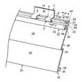
- FIG. 3is a perspective view of the siding clip of FIG. 1, shown attached to a siding panel having a channel nailing hem.
- FIG. 4is a fragmentary side elevation of the siding clip of FIG. 1, shown attached to a channel nailing hem of a first siding panel, and a second siding panel interlocked with the first siding panel.
- FIG. 5is a fragmentary side elevation of the siding clip of FIG. 1, shown attached to a first siding panel having a channel nailing hem with a trapezoidal configuration, and a second siding panel interlocked with the first siding panel.
- FIG. 6is a perspective view, shown partially broken away, of two horizontally adjacent siding panels secured to one another with a splicing member, and a siding clip of FIG. 1 attached to each of the siding panels.
- FIG. 7is a side elevation of an alternative embodiment of a siding clip of the present invention.
- the present inventionpertains to a clip for slidably securing siding panels to a structure.
- the clip and the panelsare typically composed of metal or plastic, e.g., PVC, but are not intended to be so limited, and may be formed of any suitable material.
- the clipis made of aluminum. The clip allows siding panels to be safely secured to a building or other structure, while providing horizontal, or longitudinal, movement of the panels, thereby allowing for thermal expansion and contraction of the siding panels.
- a clip 2 in accordance with the inventioncomprises a planar sheet of material 4 .
- a pair of forward legs 6are each formed by bending a lower portion of planar sheet 4 outwardly to form a shoulder 8 extending outwardly from the planar sheet.
- shoulder 8extends perpendicular to planar sheet 4 .
- Forward legs 6are then bent downwardly and inwardly with respect to the planar sheet 4 , forming a U-shaped flange 9 defining a channel 10 opening toward the planar sheet 4 .
- a lower portion of planar sheet 4positioned between and below forward legs 6 , is bent outwardly to form a rearward leg 12 .
- Rearward leg 12preferably extends perpendicular to planar sheet 4 .
- An aperture 14is formed in planar sheet 4 above forward legs 6 to receive a fastener, such as a nail, for securing clip 2 to a structure.
- Clip 2is configured to secure a siding panel, having a channel nailing hem, to a structure.
- a siding panel having a channel nailing hemis disclosed in commonly owned application Ser. No. 09/321,739, entitled “Interlocking Panel With Channel Nailing Hem,” filed on May 28, 1999, the entire disclosure of which is incorporated herein by reference for all purposes.
- a siding panel 20has a top lock 22 , a bottom lock 24 , and a body portion 26 .
- Body portioncan have a wide variety of configurations, but preferably includes a pair of declinations 28 separated by a horizontal ledge or shoulder 30 .
- a declinationrefers to a substantially planar portion of a siding panel which slopes downwardly and slightly outwardly with respect to the panel. The declinations combine with the horizontal shoulder to form a clapboard profile for the siding panel. It is to be appreciated that in other preferred embodiments, siding panel 20 may have one or more than two declinations 28 .
- top and bottom lockscan also have a wide range of shapes.
- Top and bottom locks 22 , 24have complimentary shapes so that vertically adjacent siding panels can be interlocked, as seen in FIG. 4 .
- top lock 22is bent to form a dogleg protrusion 32 which extends downwardly over siding panel 20 forming a rearwardly opening channel 33 and a downwardly opening channel 34 .
- Bottom lock 24has a shoulder 36 extending inwardly from a lower edge of body portion 26 and terminates in a lip 38 extending upwardly from a rear edge of shoulder 36 .
- top lock 22 of the lower siding panel 20interlocks with bottom lock 24 of the upper siding panel 20 .
- Shoulder 36 of the upper siding panel 20is positioned beneath protrusion 32 of the lower siding panel 20 and lip 38 of the upper siding panel is received by channel 34 of the lower siding panel.
- Siding panel 20has a channel nailing hem 40 provided above top lock 22 .
- Nailing hem 40includes a channel 42 defined by a channel base 44 and channel sides 46 and 48 .
- Channel sides 46 , 48are generally parallel to one another and channel 42 is open to one end opposite channel base 44 .
- the upper portion of nailing hem 40includes a flange 47 extending upwardly from the outer edge of channel side 46 .
- Shoulder 49extends rearwardly from flange 47 and terminates in upwardly extending lip 53 .
- Channel side 46 , flange 47 and shoulder 49form a rearwardly opening channel 51 .
- a clip 2is snap-fit with channel nailing hem 40 from the front of siding panel 20 .
- clip 2can be carried by an installer and placed on panel 20 at any desired location. This provides an installer with the flexibility of selecting a spot on the panel at which a clip is required, while the panel is in place on a structure, eliminating the need to determine ahead of time exactly how many clips will be needed for a particular panel. Therefore, considerable time and expense savings can be realized in the situation where it is determined, after the panel is in place, that another clip is required. Without the capability of installing a clip while the panel is in place, the installer would need to access the end of the panel to slide another clip on, which might entail taking the panel down from the structure.
- Clip 2is installed from the front of siding panel 20 by temporarily locating rearward leg 12 in channel 51 at a desired position along the length of siding panel 20 .
- the top of clip 2is then tilted forwardly, and as forward legs 6 snap onto nailing hem 40 , rearward leg 12 slides out of channel 51 .
- Clip 2is then tilted rearwardly, allowing forward legs 6 to rotate about channel side wall 46 , flange 47 and shoulder 49 of nailing hem 40 .
- As clip 2 rotatesrear leg 12 slides into channel 33 .
- rear leg 12is received by channel 33 and forward leg 6 interlocks with nailing hem 40 .
- flange 9 of each forward leg 6wraps around nailing hem 40 , such that channel side wall 46 , flange 47 and shoulder 49 are received by channel 10 of clip 2 , and flange 9 is partially received by channel 42 of nailing hem 40 .
- Clip 2is then securely fastened to a structure by a nail 50 , or any other suitable fastener. Therefore, clip 2 safely secures siding panel 20 to a structure, but advantageously allows the siding panel to slide longitudinally along clip 2 , providing for expansion and contraction of the siding panel 20 .
- FIG. 5shows a clip 2 interlocked with a siding panel 20 ′ having a nailing hem of a different configuration.
- Nailing hem 40 ′has a trapezoidal cross-section comprising channel base 44 forming the wide base of the trapezoid, with channel sides 46 ′, 48 ′ being angled to form the converging sides of the trapezoid.
- the narrower end of the trapezoidforms the open end of channel 42 ′. Consequently, channel 51 ′ has a trapezoidal shape as well.
- Clip 2interlocks with nailing hem 40 ′ in the manner described above with respect to nailing hem 40 . While the embodiments of the channel nailing hem discussed herein include the rectangular and trapezoidal cross-sections, other cross-sectional shapes of the channel nailing hem which would interlock with the clip are contemplated to be within the scope of the present invention.
- the nailing hem and/or top lock of the siding panelmay be reinforced to provide added rigidity for the siding panel.
- the clip of the present inventionwill interlock with such a reinforced siding panel in the same manner as described above.
- FIG. 6illustrates the use of clip 2 with a pair of horizontally adjacent siding panels secured to one another with a splicing member.
- a splicing memberis disclosed in commonly owned application Ser. No. 09/122,333, entitled “Splicing Member for Siding Panels,” filed on Jul. 24, 1998, the entire disclosure of which is incorporated herein by reference for all purposes.
- Splicing member 52comprises a body portion 54 .
- Body portion 54has a shape configured to match that of the horizontally adjacent siding panels 20 behind which splicing member 52 is positioned.
- body portion 54includes two declinations 56 separated by a shoulder 58 .
- Splicing member 52further includes a splicer top lock 60 and a splicer bottom lock 62 .
- Top and bottom locks 60 , 62are configured to interlock with and engage top and bottom locks 22 , 24 , respectively, of siding panels 20 .
- top lock 60comprises a shoulder 64 extending forwardly from a top edge of splicing member 52
- bottom lock 62comprises a shoulder 66 extending rearwardly from a lower edge of splicing member 52 .
- Splicing member 52is rigidly secured to siding panels 20 by fasteners 68 .
- Fasteners 68may be rivets, screws, adhesive, or other mechanical fasteners. In other preferred embodiments, splicing member 52 may be secured to siding panels 20 by welding or other suitable fastening means.
- FIG. 7Another embodiment of the clip of the present invention is shown in FIG. 7 .
- Clip 72is formed of a planar sheet of material folded upon itself, forming upper folded edge 74 and forward leg 76 and rearward leg 78 depending from upper folded edge 74 .
- a lower portion of forward leg 76is folded outwardly at horizontal bend 79 , forming shoulder 80 , and then downwardly and inwardly to form U-shaped flange 81 defining channel 82 opening toward rearward leg 78 .
- shoulder 80extends perpendicular to forward leg 76 .
- Rearward leg 78is bent forwardly at horizontal bend 83 to form shoulder 84 .
- shoulder 84extends perpendicular to rearward leg 78 .
- Apertures 86 , 88are formed in forward and rearward legs 76 , 78 , respectively, to receive a nail or other suitable fastener.
- the embodiments described hereinare directed to clips for siding panels extending horizontally along a wall of a structure and having a top lock and a bottom lock, it is contemplated within the scope of the invention to apply the clips to siding panels that may be differently oriented when installed.
- the clipswill slidably secure siding panels having first and second edge structures and a channel nailing hem located between the edge structures.
Landscapes
- Engineering & Computer Science (AREA)
- Architecture (AREA)
- Civil Engineering (AREA)
- Structural Engineering (AREA)
- Finishing Walls (AREA)
Abstract
Description
Claims (20)
Priority Applications (1)
| Application Number | Priority Date | Filing Date | Title |
|---|---|---|---|
| US09/497,545US6367220B1 (en) | 2000-02-03 | 2000-02-03 | Clip for siding panel |
Applications Claiming Priority (1)
| Application Number | Priority Date | Filing Date | Title |
|---|---|---|---|
| US09/497,545US6367220B1 (en) | 2000-02-03 | 2000-02-03 | Clip for siding panel |
Publications (1)
| Publication Number | Publication Date |
|---|---|
| US6367220B1true US6367220B1 (en) | 2002-04-09 |
Family
ID=23977295
Family Applications (1)
| Application Number | Title | Priority Date | Filing Date |
|---|---|---|---|
| US09/497,545Expired - Fee RelatedUS6367220B1 (en) | 2000-02-03 | 2000-02-03 | Clip for siding panel |
Country Status (1)
| Country | Link |
|---|---|
| US (1) | US6367220B1 (en) |
Cited By (69)
| Publication number | Priority date | Publication date | Assignee | Title |
|---|---|---|---|---|
| US20030046891A1 (en)* | 2001-04-03 | 2003-03-13 | Colada Jerrico Q. | Two-piece siding plank and methods of making and installing the same |
| US20030131551A1 (en)* | 2000-11-20 | 2003-07-17 | Crane Plastics Company Llc | Vinyl siding |
| US20040065024A1 (en)* | 2002-10-02 | 2004-04-08 | Kottman Mark A. | Universal wall panel tile connector |
| US20040074188A1 (en)* | 2002-10-18 | 2004-04-22 | Beck David Herbert | Clapboard siding installation clip and method of installing clapboard siding |
| US20040182039A1 (en)* | 2003-03-21 | 2004-09-23 | Bess Steven W. | Clip for installing siding |
| US6874290B1 (en)* | 2003-09-12 | 2005-04-05 | Ted R. Bokan | Siding system |
| US6886268B1 (en) | 2003-12-22 | 2005-05-03 | Certainteed Corporation | Siding installation tool and method of installing siding |
| US20050108965A1 (en)* | 2003-11-26 | 2005-05-26 | Morse Rick J. | Clapboard siding panel with built in fastener support |
| US20050268568A1 (en)* | 2003-06-26 | 2005-12-08 | Yee-Hyeng Kim | Backflow prevention cap for panels having interlocking folds |
| US6988345B1 (en) | 2003-02-03 | 2006-01-24 | Crane Plastics Company Llc | Lineal |
| US20060026921A1 (en)* | 2004-08-05 | 2006-02-09 | Associated Materials, Inc., D/B/A Alside | Splicer for siding panel assembly |
| US20060026920A1 (en)* | 2000-11-20 | 2006-02-09 | Fairbanks Larry R | Straight face vinyl siding |
| US20060053948A1 (en)* | 2003-05-28 | 2006-03-16 | Akhil Mahendra | Variable ratio brake pedal linkage mechanism |
| US20060117694A1 (en)* | 2004-11-24 | 2006-06-08 | Godby Jerry R | Clip for attaching siding |
| WO2006064268A1 (en)* | 2004-12-16 | 2006-06-22 | Ibstock Brick Limited | Fastener, cladding system and panel for use therein |
| US20060213142A1 (en)* | 2003-03-11 | 2006-09-28 | Albracht Gregory P | Siding and overhang attachment and alignment system |
| US7117651B2 (en) | 2003-04-03 | 2006-10-10 | Certainteed Corporation | Rainscreen clapboard siding |
| US20070107357A1 (en)* | 2005-11-04 | 2007-05-17 | O'neal Jerry D | Fastener guide for siding |
| US20070144096A1 (en)* | 2005-11-04 | 2007-06-28 | O'neal Jerry D | Fastener guiude for siding |
| US20070144095A1 (en)* | 2005-12-22 | 2007-06-28 | Tapco International Corporation | System for providing a decorative covering on a support surface using panels with interlocks |
| US20070234674A1 (en)* | 2006-03-21 | 2007-10-11 | Martin Hadlum | Disposable siding clip |
| US7325325B2 (en) | 2000-02-28 | 2008-02-05 | James Hardle International Finance B.V. | Surface groove system for building sheets |
| US20090000244A1 (en)* | 2005-11-04 | 2009-01-01 | O'neal Jerry D | Fastener guide for siding |
| US20090064599A1 (en)* | 2007-09-12 | 2009-03-12 | Flashing By Design, Inc. | Siding system and method |
| US7524555B2 (en) | 1999-11-19 | 2009-04-28 | James Hardie International Finance B.V. | Pre-finished and durable building material |
| US20090241458A1 (en)* | 2008-03-27 | 2009-10-01 | Ko Das | Siding Panel Assembly With Splicing Member and Insulating Panel |
| US20090241455A1 (en)* | 2008-04-01 | 2009-10-01 | Griffiths Robert T | Wall panel system with hook-on clip |
| US7685787B1 (en) | 2005-12-28 | 2010-03-30 | Crane Building Products Llc | System and method for leveling or alignment of panels |
| US7698867B1 (en)* | 2007-06-13 | 2010-04-20 | Stucko Craig B | Siding trim clip with triangular gripping pattern |
| US7721488B1 (en) | 2005-10-05 | 2010-05-25 | Bennett Scott A | Flashing apparatus for external use on structures |
| US7726092B1 (en) | 2003-10-09 | 2010-06-01 | The Crane Group Companies Limited | Window sill and trim corner assembly |
| US7730694B1 (en)* | 2004-07-07 | 2010-06-08 | Harold Simpson, Inc. | Sliding clip with extended travel |
| US20100224752A1 (en)* | 2009-03-09 | 2010-09-09 | Helen Of Troy Limited | Instrument stand for attachment to a wire grill surface or the like |
| US20100251647A1 (en)* | 2009-04-07 | 2010-10-07 | Douglas Brent Enns | Rainscreen attachment system |
| US20100281801A1 (en)* | 2008-10-28 | 2010-11-11 | Certain Teed Corporation | Foamed Building Panel, Clip and System for Installation |
| US7934352B1 (en) | 2003-10-17 | 2011-05-03 | Exterior Portfolio, Llc | Grooved foam backed panels |
| US7993570B2 (en) | 2002-10-07 | 2011-08-09 | James Hardie Technology Limited | Durable medium-density fibre cement composite |
| US7998571B2 (en) | 2004-07-09 | 2011-08-16 | James Hardie Technology Limited | Composite cement article incorporating a powder coating and methods of making same |
| US8006456B1 (en)* | 2008-06-10 | 2011-08-30 | Robert Dallas Green | Elevated retainer for roofing tiles |
| US8006455B1 (en) | 2004-12-29 | 2011-08-30 | Exterior Portfolio, Llc | Backed panel and system for connecting backed panels |
| US20120055111A1 (en)* | 2009-03-05 | 2012-03-08 | Cupa Innovacion S.L.U. | Covering for vertical surfaces and roofs |
| US20120102865A1 (en)* | 2010-11-01 | 2012-05-03 | Armstrong World Industries, Inc. | Suspended ceiling system, securing members, and process of installing a suspended ceiling system |
| US20120153108A1 (en)* | 2010-12-16 | 2012-06-21 | Timothy Wayne Schneider | Device for hanging an object on a wall |
| US8225567B1 (en) | 2003-10-17 | 2012-07-24 | Exterior Portfolio, Llc | Siding having backer with features for drainage, ventilation, and receiving adhesive |
| US8225568B1 (en) | 2003-10-17 | 2012-07-24 | Exterior Portfolio, Llc | Backed building structure panel having grooved and ribbed surface |
| US20120251227A1 (en)* | 2011-04-01 | 2012-10-04 | Danny Owens | Fastener for vinyl siding |
| US8281535B2 (en) | 2002-07-16 | 2012-10-09 | James Hardie Technology Limited | Packaging prefinished fiber cement articles |
| US8297018B2 (en) | 2002-07-16 | 2012-10-30 | James Hardie Technology Limited | Packaging prefinished fiber cement products |
| US8336269B1 (en) | 2003-10-17 | 2012-12-25 | Exterior Portfolio Llc | Siding having facing and backing portion with grooved and ribbed backing portion surface |
| US8381472B1 (en) | 2010-06-17 | 2013-02-26 | Exterior Portfolio, Llc | System and method for adjoining siding |
| US8596000B2 (en)* | 2010-01-29 | 2013-12-03 | Royal Group, Inc. | Interlocking panel system |
| US20140123585A1 (en)* | 2011-05-03 | 2014-05-08 | Deschenes Innovations Inc. | Attachment device for sheet type construction siding |
| US8795813B2 (en) | 2011-02-22 | 2014-08-05 | Exterior Portfolio, Llc | Ribbed backed panels |
| US8875463B2 (en)* | 2012-02-21 | 2014-11-04 | Tecton Products, Llc | Siding system |
| US8915036B2 (en)* | 2013-03-08 | 2014-12-23 | Quality Edge, Inc. | Formed interlocking roofing panels |
| US20150082728A1 (en)* | 2013-09-25 | 2015-03-26 | MarPec, Inc. | Snap Lock Siding System |
| US8993462B2 (en) | 2006-04-12 | 2015-03-31 | James Hardie Technology Limited | Surface sealed reinforced building element |
| US9200456B2 (en) | 2012-07-12 | 2015-12-01 | Exterior Research & Design Llc | Joiner clip |
| US9309677B1 (en) | 2015-08-10 | 2016-04-12 | Jeffrey Sargen | Siding system |
| US20160153197A1 (en)* | 2008-12-05 | 2016-06-02 | Ted Baum, Jr. | Simulated Log Siding Panel with Hew Lines |
| US9624675B2 (en) | 2013-01-27 | 2017-04-18 | Fiber Cement Foam Systems Insulation, LLC | Method and device to attach building siding boards |
| US10156066B2 (en) | 2017-05-11 | 2018-12-18 | Calaco Solutions Ltd. | Corner bead clip for attaching to steel members |
| US10494819B1 (en) | 2018-06-12 | 2019-12-03 | Exterior Research And Design, L.L.C. | Joiner clip |
| US10550578B2 (en) | 2018-06-20 | 2020-02-04 | Jerry D. O'Neal | Siding attachment system |
| US10753099B2 (en) | 2018-06-20 | 2020-08-25 | Jerry D. O'Neal | Siding attachment system |
| US20210230878A1 (en)* | 2020-01-15 | 2021-07-29 | Certainteed Llc | Siding Attachment Accessory and Siding System |
| US20210372135A1 (en)* | 2020-05-30 | 2021-12-02 | Edward Eng | Siding Panel Attachment System |
| US11447959B2 (en)* | 2019-05-21 | 2022-09-20 | Orcutt Innovations, Llc | Masonry veneer hanger and spacer |
| US11746804B2 (en) | 2019-08-02 | 2023-09-05 | Don Huizenga | Gripping bracket |
Citations (47)
| Publication number | Priority date | Publication date | Assignee | Title |
|---|---|---|---|---|
| US1232196A (en) | 1915-06-25 | 1917-07-03 | Everett Wesley Brague | Roof construction. |
| US1674210A (en) | 1925-02-13 | 1928-06-19 | Holorib Inc | Clamping device |
| US1775937A (en) | 1926-05-10 | 1930-09-16 | Patent & Licensing Corp | Roof |
| US1813798A (en) | 1930-01-25 | 1931-07-07 | Gerosa Anthony | Retainer for shingles |
| US1941216A (en) | 1930-10-13 | 1933-12-26 | John C Mckeown | Outside covering for buildings |
| US2126676A (en) | 1937-07-22 | 1938-08-09 | Frank S Thomas | Siding |
| US2141861A (en) | 1937-01-02 | 1938-12-27 | Standard Oil Dev Co | Tank roof seam |
| US2174145A (en) | 1938-10-24 | 1939-09-26 | Samuel H Tummins | Wallboard fastener |
| US2293744A (en) | 1941-03-17 | 1942-08-25 | Johns Manville | Wall construction and method and means for making the same |
| US2831222A (en) | 1955-06-15 | 1958-04-22 | Wood Conversion Co | Wallboard clip |
| US3226901A (en) | 1961-10-13 | 1966-01-04 | Panel Craft Inc | Building siding structure |
| US3233382A (en) | 1962-08-30 | 1966-02-08 | Alside Inc | Aluminum siding panel having interlocking marginal edges |
| US3282009A (en) | 1963-06-28 | 1966-11-01 | Brixite Mfg Co Inc | Metal siding |
| US3418777A (en) | 1967-03-29 | 1968-12-31 | Sam Greenebaum | Roofing |
| US3438168A (en) | 1966-06-08 | 1969-04-15 | Robertson Co H H | Building outer wall structure |
| US3504467A (en) | 1968-04-25 | 1970-04-07 | Monsanto Co | Siding |
| US3520099A (en) | 1968-09-16 | 1970-07-14 | Mastic Corp | Interlocking building siding unit |
| US3711137A (en) | 1970-09-30 | 1973-01-16 | G Tinnerman | Lath to stud clip |
| US3738076A (en) | 1971-09-07 | 1973-06-12 | G Kessler | Nailing clip for plastic siding |
| US3757483A (en) | 1971-08-13 | 1973-09-11 | Alsco Anaconda Inc | Sill trim strip and panel siding |
| US3969866A (en) | 1973-04-16 | 1976-07-20 | P.J.K. Projects Limited | Sheet assemblies and sheets therefor |
| US3999348A (en) | 1975-09-30 | 1976-12-28 | Ball Corporation | Watertight roof construction |
| US4186538A (en) | 1978-05-10 | 1980-02-05 | Aluminum Industries, Inc. | Panel of siding |
| US4255914A (en) | 1978-10-23 | 1981-03-17 | Automated Building Components, Inc. | Clip for securing planar members |
| US4272938A (en) | 1978-10-23 | 1981-06-16 | Automated Building Components, Inc. | Sheet metal clip for assembly of building components |
| US4296580A (en) | 1978-09-29 | 1981-10-27 | Weinar Roger N | Wall constructed from panels held in position with the aid of concealed fasteners and concealable fasteners for use in assembling such wall |
| US4327528A (en) | 1980-02-29 | 1982-05-04 | Wolverine Aluminum Corporation | Insulated siding system |
| US4348849A (en) | 1980-08-11 | 1982-09-14 | Alcan Aluminum Corporation | Starter strip for horizontal siding panels |
| US4356673A (en) | 1980-08-11 | 1982-11-02 | Alcan Aluminum Corporation | Siding panel systems and methods of installation |
| US4382354A (en) | 1981-04-28 | 1983-05-10 | Alcan Aluminum Corporation | Siding panel systems with panel-mounting devices |
| US4435938A (en) | 1981-11-12 | 1984-03-13 | National Gypsum Company | Vinyl siding attachment |
| US4435933A (en) | 1981-08-10 | 1984-03-13 | National Gypsum Company | Vinyl siding attachment |
| US4498272A (en) | 1982-05-20 | 1985-02-12 | Rollform, Incorporated | Panel fastener |
| US4575983A (en) | 1985-02-01 | 1986-03-18 | Nucor Corporation | Sliding hold-down clip for standing seam metal roof |
| US4596094A (en) | 1981-03-03 | 1986-06-24 | Gte Products Corporation | Panel fastener for a movable wall assembly |
| US4646501A (en) | 1985-02-14 | 1987-03-03 | Chw Enterprises, Inc. | Starter bracket for installing aluminum siding |
| US4669238A (en) | 1986-03-21 | 1987-06-02 | Wolverine Technologies, Inc. | Plastic siding mounting system |
| US4698942A (en) | 1985-05-09 | 1987-10-13 | Swartz Gary D | Clip for holding and spacing siding panels |
| US4856744A (en)* | 1988-06-01 | 1989-08-15 | Gail Frankel | Handle support assembly |
| US4947609A (en) | 1989-07-10 | 1990-08-14 | Champagne Charles A | Top out panel mounting clip for vinyl siding |
| USD316810S (en) | 1986-08-14 | 1991-05-14 | James Hardie & Coy Pty. Limited | Clip for butt joining siding |
| US5058358A (en) | 1990-08-10 | 1991-10-22 | Midwest Industries Ltd. | Hanger bracket apparatus for securing a joist member to an elevated vertical support surface |
| US5127205A (en)* | 1990-11-05 | 1992-07-07 | Eidson Carson J | Support clip for roofing panels and associated system |
| US5150555A (en) | 1991-07-12 | 1992-09-29 | Wood Larry A | Siding clip |
| US5339608A (en) | 1991-12-13 | 1994-08-23 | C & H Enterprises | Mounting clip for vinyl siding |
| US5526553A (en)* | 1994-10-24 | 1996-06-18 | Unisys Corporation | Snap-lock spring clip attachment system |
| US5622020A (en) | 1995-12-05 | 1997-04-22 | Wood; Margaret A. | Attachment clip for horizontal siding panels |
- 2000
- 2000-02-03USUS09/497,545patent/US6367220B1/ennot_activeExpired - Fee Related
Patent Citations (47)
| Publication number | Priority date | Publication date | Assignee | Title |
|---|---|---|---|---|
| US1232196A (en) | 1915-06-25 | 1917-07-03 | Everett Wesley Brague | Roof construction. |
| US1674210A (en) | 1925-02-13 | 1928-06-19 | Holorib Inc | Clamping device |
| US1775937A (en) | 1926-05-10 | 1930-09-16 | Patent & Licensing Corp | Roof |
| US1813798A (en) | 1930-01-25 | 1931-07-07 | Gerosa Anthony | Retainer for shingles |
| US1941216A (en) | 1930-10-13 | 1933-12-26 | John C Mckeown | Outside covering for buildings |
| US2141861A (en) | 1937-01-02 | 1938-12-27 | Standard Oil Dev Co | Tank roof seam |
| US2126676A (en) | 1937-07-22 | 1938-08-09 | Frank S Thomas | Siding |
| US2174145A (en) | 1938-10-24 | 1939-09-26 | Samuel H Tummins | Wallboard fastener |
| US2293744A (en) | 1941-03-17 | 1942-08-25 | Johns Manville | Wall construction and method and means for making the same |
| US2831222A (en) | 1955-06-15 | 1958-04-22 | Wood Conversion Co | Wallboard clip |
| US3226901A (en) | 1961-10-13 | 1966-01-04 | Panel Craft Inc | Building siding structure |
| US3233382A (en) | 1962-08-30 | 1966-02-08 | Alside Inc | Aluminum siding panel having interlocking marginal edges |
| US3282009A (en) | 1963-06-28 | 1966-11-01 | Brixite Mfg Co Inc | Metal siding |
| US3438168A (en) | 1966-06-08 | 1969-04-15 | Robertson Co H H | Building outer wall structure |
| US3418777A (en) | 1967-03-29 | 1968-12-31 | Sam Greenebaum | Roofing |
| US3504467A (en) | 1968-04-25 | 1970-04-07 | Monsanto Co | Siding |
| US3520099A (en) | 1968-09-16 | 1970-07-14 | Mastic Corp | Interlocking building siding unit |
| US3711137A (en) | 1970-09-30 | 1973-01-16 | G Tinnerman | Lath to stud clip |
| US3757483A (en) | 1971-08-13 | 1973-09-11 | Alsco Anaconda Inc | Sill trim strip and panel siding |
| US3738076A (en) | 1971-09-07 | 1973-06-12 | G Kessler | Nailing clip for plastic siding |
| US3969866A (en) | 1973-04-16 | 1976-07-20 | P.J.K. Projects Limited | Sheet assemblies and sheets therefor |
| US3999348A (en) | 1975-09-30 | 1976-12-28 | Ball Corporation | Watertight roof construction |
| US4186538A (en) | 1978-05-10 | 1980-02-05 | Aluminum Industries, Inc. | Panel of siding |
| US4296580A (en) | 1978-09-29 | 1981-10-27 | Weinar Roger N | Wall constructed from panels held in position with the aid of concealed fasteners and concealable fasteners for use in assembling such wall |
| US4255914A (en) | 1978-10-23 | 1981-03-17 | Automated Building Components, Inc. | Clip for securing planar members |
| US4272938A (en) | 1978-10-23 | 1981-06-16 | Automated Building Components, Inc. | Sheet metal clip for assembly of building components |
| US4327528A (en) | 1980-02-29 | 1982-05-04 | Wolverine Aluminum Corporation | Insulated siding system |
| US4348849A (en) | 1980-08-11 | 1982-09-14 | Alcan Aluminum Corporation | Starter strip for horizontal siding panels |
| US4356673A (en) | 1980-08-11 | 1982-11-02 | Alcan Aluminum Corporation | Siding panel systems and methods of installation |
| US4596094A (en) | 1981-03-03 | 1986-06-24 | Gte Products Corporation | Panel fastener for a movable wall assembly |
| US4382354A (en) | 1981-04-28 | 1983-05-10 | Alcan Aluminum Corporation | Siding panel systems with panel-mounting devices |
| US4435933A (en) | 1981-08-10 | 1984-03-13 | National Gypsum Company | Vinyl siding attachment |
| US4435938A (en) | 1981-11-12 | 1984-03-13 | National Gypsum Company | Vinyl siding attachment |
| US4498272A (en) | 1982-05-20 | 1985-02-12 | Rollform, Incorporated | Panel fastener |
| US4575983A (en) | 1985-02-01 | 1986-03-18 | Nucor Corporation | Sliding hold-down clip for standing seam metal roof |
| US4646501A (en) | 1985-02-14 | 1987-03-03 | Chw Enterprises, Inc. | Starter bracket for installing aluminum siding |
| US4698942A (en) | 1985-05-09 | 1987-10-13 | Swartz Gary D | Clip for holding and spacing siding panels |
| US4669238A (en) | 1986-03-21 | 1987-06-02 | Wolverine Technologies, Inc. | Plastic siding mounting system |
| USD316810S (en) | 1986-08-14 | 1991-05-14 | James Hardie & Coy Pty. Limited | Clip for butt joining siding |
| US4856744A (en)* | 1988-06-01 | 1989-08-15 | Gail Frankel | Handle support assembly |
| US4947609A (en) | 1989-07-10 | 1990-08-14 | Champagne Charles A | Top out panel mounting clip for vinyl siding |
| US5058358A (en) | 1990-08-10 | 1991-10-22 | Midwest Industries Ltd. | Hanger bracket apparatus for securing a joist member to an elevated vertical support surface |
| US5127205A (en)* | 1990-11-05 | 1992-07-07 | Eidson Carson J | Support clip for roofing panels and associated system |
| US5150555A (en) | 1991-07-12 | 1992-09-29 | Wood Larry A | Siding clip |
| US5339608A (en) | 1991-12-13 | 1994-08-23 | C & H Enterprises | Mounting clip for vinyl siding |
| US5526553A (en)* | 1994-10-24 | 1996-06-18 | Unisys Corporation | Snap-lock spring clip attachment system |
| US5622020A (en) | 1995-12-05 | 1997-04-22 | Wood; Margaret A. | Attachment clip for horizontal siding panels |
Cited By (108)
| Publication number | Priority date | Publication date | Assignee | Title |
|---|---|---|---|---|
| US7524555B2 (en) | 1999-11-19 | 2009-04-28 | James Hardie International Finance B.V. | Pre-finished and durable building material |
| US7325325B2 (en) | 2000-02-28 | 2008-02-05 | James Hardle International Finance B.V. | Surface groove system for building sheets |
| US7204062B2 (en) | 2000-11-20 | 2007-04-17 | Crane Plastics Company Llc | Straight face vinyl siding |
| US7467500B2 (en) | 2000-11-20 | 2008-12-23 | Crane Building Products Llc | Straight face siding |
| US20030131551A1 (en)* | 2000-11-20 | 2003-07-17 | Crane Plastics Company Llc | Vinyl siding |
| US7984597B2 (en) | 2000-11-20 | 2011-07-26 | Exterior Portfolio, Llc | Vinyl siding |
| US20060026920A1 (en)* | 2000-11-20 | 2006-02-09 | Fairbanks Larry R | Straight face vinyl siding |
| US20030046891A1 (en)* | 2001-04-03 | 2003-03-13 | Colada Jerrico Q. | Two-piece siding plank and methods of making and installing the same |
| US7713615B2 (en) | 2001-04-03 | 2010-05-11 | James Hardie International Finance B.V. | Reinforced fiber cement article and methods of making and installing the same |
| US8409380B2 (en) | 2001-04-03 | 2013-04-02 | James Hardie Technology Limited | Reinforced fiber cement article and methods of making and installing the same |
| US8281535B2 (en) | 2002-07-16 | 2012-10-09 | James Hardie Technology Limited | Packaging prefinished fiber cement articles |
| US8297018B2 (en) | 2002-07-16 | 2012-10-30 | James Hardie Technology Limited | Packaging prefinished fiber cement products |
| US20040065024A1 (en)* | 2002-10-02 | 2004-04-08 | Kottman Mark A. | Universal wall panel tile connector |
| US6941716B2 (en)* | 2002-10-02 | 2005-09-13 | Hni Technologies Inc. | Universal wall panel tile connector |
| US7993570B2 (en) | 2002-10-07 | 2011-08-09 | James Hardie Technology Limited | Durable medium-density fibre cement composite |
| US7441382B2 (en) | 2002-10-18 | 2008-10-28 | Certainteed Corporation | Clapboard siding installation clip and method of installing clapboard siding |
| US20040074188A1 (en)* | 2002-10-18 | 2004-04-22 | Beck David Herbert | Clapboard siding installation clip and method of installing clapboard siding |
| US6988345B1 (en) | 2003-02-03 | 2006-01-24 | Crane Plastics Company Llc | Lineal |
| US20060213142A1 (en)* | 2003-03-11 | 2006-09-28 | Albracht Gregory P | Siding and overhang attachment and alignment system |
| US20040182039A1 (en)* | 2003-03-21 | 2004-09-23 | Bess Steven W. | Clip for installing siding |
| US20070074483A1 (en)* | 2003-04-03 | 2007-04-05 | Certainteed Corporation | Rainscreen clapboard siding |
| US7117651B2 (en) | 2003-04-03 | 2006-10-10 | Certainteed Corporation | Rainscreen clapboard siding |
| US7472523B2 (en) | 2003-04-03 | 2009-01-06 | Certainteed Corporation | Rainscreen clapboard siding |
| US20060053948A1 (en)* | 2003-05-28 | 2006-03-16 | Akhil Mahendra | Variable ratio brake pedal linkage mechanism |
| US20050268568A1 (en)* | 2003-06-26 | 2005-12-08 | Yee-Hyeng Kim | Backflow prevention cap for panels having interlocking folds |
| US6874290B1 (en)* | 2003-09-12 | 2005-04-05 | Ted R. Bokan | Siding system |
| US7726092B1 (en) | 2003-10-09 | 2010-06-01 | The Crane Group Companies Limited | Window sill and trim corner assembly |
| US8555582B2 (en) | 2003-10-17 | 2013-10-15 | Exterior Portfolio, Llc | Siding having facing and backing portion with grooved and ribbed backing portion surface |
| US8225568B1 (en) | 2003-10-17 | 2012-07-24 | Exterior Portfolio, Llc | Backed building structure panel having grooved and ribbed surface |
| US8336269B1 (en) | 2003-10-17 | 2012-12-25 | Exterior Portfolio Llc | Siding having facing and backing portion with grooved and ribbed backing portion surface |
| US8225567B1 (en) | 2003-10-17 | 2012-07-24 | Exterior Portfolio, Llc | Siding having backer with features for drainage, ventilation, and receiving adhesive |
| US7934352B1 (en) | 2003-10-17 | 2011-05-03 | Exterior Portfolio, Llc | Grooved foam backed panels |
| US20050108965A1 (en)* | 2003-11-26 | 2005-05-26 | Morse Rick J. | Clapboard siding panel with built in fastener support |
| US6886268B1 (en) | 2003-12-22 | 2005-05-03 | Certainteed Corporation | Siding installation tool and method of installing siding |
| US7730694B1 (en)* | 2004-07-07 | 2010-06-08 | Harold Simpson, Inc. | Sliding clip with extended travel |
| US7998571B2 (en) | 2004-07-09 | 2011-08-16 | James Hardie Technology Limited | Composite cement article incorporating a powder coating and methods of making same |
| US20060026921A1 (en)* | 2004-08-05 | 2006-02-09 | Associated Materials, Inc., D/B/A Alside | Splicer for siding panel assembly |
| US7478507B2 (en)* | 2004-08-05 | 2009-01-20 | Associated Materials, Llc. | Splicer and siding panel assembly |
| US20060117694A1 (en)* | 2004-11-24 | 2006-06-08 | Godby Jerry R | Clip for attaching siding |
| US7581364B2 (en)* | 2004-11-24 | 2009-09-01 | Godby Jerry R | Clip for attaching siding |
| WO2006064268A1 (en)* | 2004-12-16 | 2006-06-22 | Ibstock Brick Limited | Fastener, cladding system and panel for use therein |
| US8006455B1 (en) | 2004-12-29 | 2011-08-30 | Exterior Portfolio, Llc | Backed panel and system for connecting backed panels |
| US9309678B1 (en) | 2004-12-29 | 2016-04-12 | Paul J. Mollinger | Backed panel and system for connecting backed panels |
| US9816277B2 (en) | 2004-12-29 | 2017-11-14 | Royal Building Products (Usa) Inc. | Backed panel and system for connecting backed panels |
| US7721488B1 (en) | 2005-10-05 | 2010-05-25 | Bennett Scott A | Flashing apparatus for external use on structures |
| US20100218434A1 (en)* | 2005-10-05 | 2010-09-02 | Bennett Scott A | Flashing apparatus for external use on structures |
| US7980038B2 (en) | 2005-11-04 | 2011-07-19 | O'neal Jerry D | Fastener guide for siding |
| US20090000244A1 (en)* | 2005-11-04 | 2009-01-01 | O'neal Jerry D | Fastener guide for siding |
| US20070107357A1 (en)* | 2005-11-04 | 2007-05-17 | O'neal Jerry D | Fastener guide for siding |
| US20070144096A1 (en)* | 2005-11-04 | 2007-06-28 | O'neal Jerry D | Fastener guiude for siding |
| US7441383B2 (en) | 2005-11-04 | 2008-10-28 | O'neal Jerry D | Fastener guide for siding |
| US20110036037A1 (en)* | 2005-12-22 | 2011-02-17 | Tapco International Corporation | System for providing a decorative covering on a support surface using panels with interlocks |
| US7775009B2 (en)* | 2005-12-22 | 2010-08-17 | Tapco International Corporation | System for providing a decorative covering on a support surface using panels with interlocks |
| US20070144095A1 (en)* | 2005-12-22 | 2007-06-28 | Tapco International Corporation | System for providing a decorative covering on a support surface using panels with interlocks |
| US7685787B1 (en) | 2005-12-28 | 2010-03-30 | Crane Building Products Llc | System and method for leveling or alignment of panels |
| US20070234674A1 (en)* | 2006-03-21 | 2007-10-11 | Martin Hadlum | Disposable siding clip |
| US8993462B2 (en) | 2006-04-12 | 2015-03-31 | James Hardie Technology Limited | Surface sealed reinforced building element |
| US7698867B1 (en)* | 2007-06-13 | 2010-04-20 | Stucko Craig B | Siding trim clip with triangular gripping pattern |
| US7784222B2 (en)* | 2007-09-12 | 2010-08-31 | Flashing By Design, Inc. | Siding system and method |
| US20090064599A1 (en)* | 2007-09-12 | 2009-03-12 | Flashing By Design, Inc. | Siding system and method |
| US20090241458A1 (en)* | 2008-03-27 | 2009-10-01 | Ko Das | Siding Panel Assembly With Splicing Member and Insulating Panel |
| US20090241455A1 (en)* | 2008-04-01 | 2009-10-01 | Griffiths Robert T | Wall panel system with hook-on clip |
| US8191327B2 (en)* | 2008-04-01 | 2012-06-05 | Firestone Building Products Company, Llc | Wall panel system with hook-on clip |
| US8151534B1 (en)* | 2008-06-10 | 2012-04-10 | Robert Dallas Green | Elevated retainer for roofing tiles |
| US8006456B1 (en)* | 2008-06-10 | 2011-08-30 | Robert Dallas Green | Elevated retainer for roofing tiles |
| US8516765B2 (en)* | 2008-10-28 | 2013-08-27 | Certainteed Corporation | Foamed building panel, clip and system for installation |
| US20100281801A1 (en)* | 2008-10-28 | 2010-11-11 | Certain Teed Corporation | Foamed Building Panel, Clip and System for Installation |
| US20160153197A1 (en)* | 2008-12-05 | 2016-06-02 | Ted Baum, Jr. | Simulated Log Siding Panel with Hew Lines |
| US9732529B2 (en)* | 2008-12-05 | 2017-08-15 | Ted Baum, Jr. | Simulated log siding panel with hew lines |
| US20120055111A1 (en)* | 2009-03-05 | 2012-03-08 | Cupa Innovacion S.L.U. | Covering for vertical surfaces and roofs |
| US8667758B2 (en)* | 2009-03-05 | 2014-03-11 | Cupa Innovacion S.L.U. | Covering for vertical surfaces and roofs |
| US20100224752A1 (en)* | 2009-03-09 | 2010-09-09 | Helen Of Troy Limited | Instrument stand for attachment to a wire grill surface or the like |
| US8453984B2 (en)* | 2009-03-09 | 2013-06-04 | Helen Of Troy Limited | Instrument stand for attachment to a wire grill surface or the like |
| US8336273B2 (en)* | 2009-04-07 | 2012-12-25 | The Board Of Regents For Oklahoma State University | Rainscreen attachment system |
| US20100251647A1 (en)* | 2009-04-07 | 2010-10-07 | Douglas Brent Enns | Rainscreen attachment system |
| US8596000B2 (en)* | 2010-01-29 | 2013-12-03 | Royal Group, Inc. | Interlocking panel system |
| US8381472B1 (en) | 2010-06-17 | 2013-02-26 | Exterior Portfolio, Llc | System and method for adjoining siding |
| US10718113B2 (en)* | 2010-11-01 | 2020-07-21 | Awi Licensing Llc | Suspended ceiling system, securing members, and process of installing a suspended ceiling system |
| US8596009B2 (en)* | 2010-11-01 | 2013-12-03 | Awi Licensing Company | Suspended ceiling system, securing members, and process of installing a suspended ceiling system |
| US20120102865A1 (en)* | 2010-11-01 | 2012-05-03 | Armstrong World Industries, Inc. | Suspended ceiling system, securing members, and process of installing a suspended ceiling system |
| US11952776B2 (en) | 2010-11-01 | 2024-04-09 | Armstrong World Industries, Inc. | Suspended ceiling system, securing members, and process of installing a suspended ceiling system |
| US11479971B2 (en) | 2010-11-01 | 2022-10-25 | Awi Licensing Llc | Suspended ceiling system, securing members, and process of installing a suspended ceiling system |
| US20190257083A1 (en)* | 2010-11-01 | 2019-08-22 | Armstrong World Industries, Inc. | Suspended ceiling system, securing members, and process of installing a suspended ceiling system |
| US20120153108A1 (en)* | 2010-12-16 | 2012-06-21 | Timothy Wayne Schneider | Device for hanging an object on a wall |
| US8371543B2 (en)* | 2010-12-16 | 2013-02-12 | Timothy Wayne Schneider | Device for hanging an object on a wall |
| US8795813B2 (en) | 2011-02-22 | 2014-08-05 | Exterior Portfolio, Llc | Ribbed backed panels |
| US9428910B2 (en) | 2011-02-22 | 2016-08-30 | Royal Building Products (Usa) Inc. | Ribbed backed panels |
| US20120251227A1 (en)* | 2011-04-01 | 2012-10-04 | Danny Owens | Fastener for vinyl siding |
| US9091078B2 (en)* | 2011-05-03 | 2015-07-28 | Deschênes Innovations Inc. | Attachment device for sheet type construction siding |
| US20140123585A1 (en)* | 2011-05-03 | 2014-05-08 | Deschenes Innovations Inc. | Attachment device for sheet type construction siding |
| US8875463B2 (en)* | 2012-02-21 | 2014-11-04 | Tecton Products, Llc | Siding system |
| US9200456B2 (en) | 2012-07-12 | 2015-12-01 | Exterior Research & Design Llc | Joiner clip |
| US9624675B2 (en) | 2013-01-27 | 2017-04-18 | Fiber Cement Foam Systems Insulation, LLC | Method and device to attach building siding boards |
| US8915036B2 (en)* | 2013-03-08 | 2014-12-23 | Quality Edge, Inc. | Formed interlocking roofing panels |
| US20150082728A1 (en)* | 2013-09-25 | 2015-03-26 | MarPec, Inc. | Snap Lock Siding System |
| US9593490B2 (en) | 2015-08-10 | 2017-03-14 | Jeffrey Sargen | Siding system |
| US9309677B1 (en) | 2015-08-10 | 2016-04-12 | Jeffrey Sargen | Siding system |
| US10156066B2 (en) | 2017-05-11 | 2018-12-18 | Calaco Solutions Ltd. | Corner bead clip for attaching to steel members |
| US10494819B1 (en) | 2018-06-12 | 2019-12-03 | Exterior Research And Design, L.L.C. | Joiner clip |
| US10550578B2 (en) | 2018-06-20 | 2020-02-04 | Jerry D. O'Neal | Siding attachment system |
| US10550579B2 (en) | 2018-06-20 | 2020-02-04 | Jerry D. O'Neal | Siding attachment system |
| US10753099B2 (en) | 2018-06-20 | 2020-08-25 | Jerry D. O'Neal | Siding attachment system |
| US11447959B2 (en)* | 2019-05-21 | 2022-09-20 | Orcutt Innovations, Llc | Masonry veneer hanger and spacer |
| US11746804B2 (en) | 2019-08-02 | 2023-09-05 | Don Huizenga | Gripping bracket |
| US12215725B2 (en) | 2019-08-02 | 2025-02-04 | Don Huizenga | Gripping bracket |
| US11905715B2 (en)* | 2020-01-15 | 2024-02-20 | Certainteed Llc | Siding attachment accessory and siding system |
| US20210230878A1 (en)* | 2020-01-15 | 2021-07-29 | Certainteed Llc | Siding Attachment Accessory and Siding System |
| US20210372135A1 (en)* | 2020-05-30 | 2021-12-02 | Edward Eng | Siding Panel Attachment System |
Similar Documents
| Publication | Publication Date | Title |
|---|---|---|
| US6367220B1 (en) | Clip for siding panel | |
| US5392579A (en) | Lipless clip for vinyl siding and method | |
| US6393792B1 (en) | Splicing member for siding panels | |
| US6050041A (en) | Splicing member for siding panels | |
| US7040067B2 (en) | Siding panel with insulated backing panel | |
| CN104870729B (en) | End Lap System for Roof Sheathing Panels | |
| US5150555A (en) | Siding clip | |
| US3903670A (en) | Apparatus and method for hanging siding members on supporting surfaces | |
| US10753099B2 (en) | Siding attachment system | |
| JP2008542596A (en) | Structural member with gripping function and joining structure thereof | |
| US20060272255A1 (en) | Modesty panel and external wall construction structure using said modesty panel | |
| IES60089B2 (en) | Improvements in or relating to construction of suspended ceilings, walls and partition walls | |
| US5784848A (en) | Roofing system and shingle | |
| EP3762562B1 (en) | Double return panel system | |
| CA2834804A1 (en) | Attachment device for sheet type construction siding | |
| WO2009120915A1 (en) | Siding assembly with splicing member and insulating panel | |
| US20250084645A1 (en) | Double return panel apparatus | |
| US4461135A (en) | Wallboard trim apparatus | |
| US20210180331A1 (en) | Hidden fastener to secure loose vinyl siding | |
| US5394666A (en) | Inverted seam roof covering system | |
| CN100482907C (en) | covering element | |
| US20070094958A1 (en) | Apparatus and methods for trim used with building siding | |
| US7047702B1 (en) | Perimeter angle trim | |
| US20240287816A1 (en) | Siding Panel with Varying Profile and Siding System | |
| US10550579B2 (en) | Siding attachment system |
Legal Events
| Date | Code | Title | Description |
|---|---|---|---|
| AS | Assignment | Owner name:ASSOCIATED MATERIALS, INCORPORATED, D/B/A ALSIDE, Free format text:ASSIGNMENT OF ASSIGNORS INTEREST;ASSIGNORS:KRAUSE, WALTER M.;MOWERY, JACK T.;MCGARRY, BENJAMIN L.;REEL/FRAME:010633/0818 Effective date:20000121 | |
| AS | Assignment | Owner name:UBS AG STAMFORD BRANCH AS, ADMINISTRATIVE AGENT, C Free format text:SECURITY AGREEMENT;ASSIGNOR:ASSOCIATED MATERIALS INCORPORATED;REEL/FRAME:012937/0353 Effective date:20020419 | |
| FPAY | Fee payment | Year of fee payment:4 | |
| AS | Assignment | Owner name:ASSOCIATED MATERIALS, LLC, OHIO Free format text:CHANGE OF NAME;ASSIGNOR:ASSOCIATED MATERIALS INCORPORATED;REEL/FRAME:021439/0018 Effective date:20071228 | |
| AS | Assignment | Owner name:WACHOVIA BANK, NATIONAL ASSOCIATION, GEORGIA Free format text:SECURITY AGREEMENT;ASSIGNOR:ASSOCIATED MATERIALS, LLC;REEL/FRAME:021669/0139 Effective date:20081003 | |
| AS | Assignment | Owner name:ASSOCIATED MATERIALS INC., NOW KNOWN AS ASSOCIATED Free format text:RELEASE OF SECURITY INTEREST RECORDED ON REEL 012937, FRAME 0353;ASSIGNOR:UBS AG, STAMFORD BRANCH, AS ADMINISTRATIVE AGENT;REEL/FRAME:021731/0367 Effective date:20081003 | |
| FPAY | Fee payment | Year of fee payment:8 | |
| AS | Assignment | Owner name:DEUTSCHE BANK TRUST COMPANY AMERICAS, AS COLLATERA Free format text:SECURITY AGREEMENT;ASSIGNORS:ASSOCIATED MATERIALS, LLC;ASSOCIATED MATERIALS FINANCE, INC.;GENTEK HOLDINGS, LLC;AND OTHERS;REEL/FRAME:023627/0731 Effective date:20091105 | |
| AS | Assignment | Owner name:ASSOCIATED MATERIALS, LLC, OHIO Free format text:RELEASE BY SECURED PARTY;ASSIGNOR:WELLS FARGO BANK, NATIONAL ASSOCIATION, AS SUCCESSOR BY MERGER TO WACHOVIA BANK NATIONAL ASSOCIATION, AS AGENT;REEL/FRAME:025137/0752 Effective date:20101012 Owner name:GENTEK BUILDING PRODUCTS, INC., OHIO Free format text:RELEASE BY SECURED PARTY;ASSIGNOR:WELLS FARGO BANK, NATIONAL ASSOCIATION, AS SUCCESSOR BY MERGER TO WACHOVIA BANK NATIONAL ASSOCIATION, AS AGENT;REEL/FRAME:025137/0752 Effective date:20101012 Owner name:GENTEK BUILDING PRODUCTS, INC., OHIO Free format text:RELEASE BY SECURED PARTY;ASSIGNOR:DEUTSCHE BANK TRUST COMPANY AMERICAS AS COLLATERAL AGENT;REEL/FRAME:025137/0732 Effective date:20101013 Owner name:ASSOCIATED MATERIALS, LLC, OHIO Free format text:RELEASE BY SECURED PARTY;ASSIGNOR:DEUTSCHE BANK TRUST COMPANY AMERICAS AS COLLATERAL AGENT;REEL/FRAME:025137/0732 Effective date:20101013 | |
| AS | Assignment | Owner name:UBS AG, STAMFORD BRANCH, AS US COLLATERAL AGENT, C Free format text:SECURITY AGREEMENT;ASSIGNOR:ASSOCIATED MATERIALS, LLC;REEL/FRAME:025150/0324 Effective date:20101013 | |
| AS | Assignment | Owner name:WELLS FARGO BANK, NATIONAL ASSOCIATION, AS NOTES C Free format text:SECURITY AGREEMENT;ASSIGNOR:ASSOCIATED MATERIALS, LLC;REEL/FRAME:025326/0586 Effective date:20101013 | |
| REMI | Maintenance fee reminder mailed | ||
| LAPS | Lapse for failure to pay maintenance fees | ||
| STCH | Information on status: patent discontinuation | Free format text:PATENT EXPIRED DUE TO NONPAYMENT OF MAINTENANCE FEES UNDER 37 CFR 1.362 | |
| FP | Lapsed due to failure to pay maintenance fee | Effective date:20140409 | |
| AS | Assignment | Owner name:ASSOCIATED MATERIALS, LLC, OHIO Free format text:RELEASE OF SECURITY INTEREST IN PATENTS PREVIOUSLY RECORDED AT REEL/FRAME (025326/0586);ASSIGNOR:WELLS FARGO BANK, NATIONAL ASSOCIATION, AS NOTES COLLATERAL AGENT;REEL/FRAME:040921/0948 Effective date:20161122 | |
| AS | Assignment | Owner name:ASSOCIATED MATERIALS, LLC, OHIO Free format text:RELEASE OF SECURITY INTEREST IN PATENTS;ASSIGNOR:UBS AG, STAMFORD BRANCH;REEL/FRAME:059337/0299 Effective date:20220308 |