US6367022B1 - Power management fault strategy for automotive multimedia system - Google Patents
Power management fault strategy for automotive multimedia systemDownload PDFInfo
- Publication number
- US6367022B1 US6367022B1US09/353,684US35368499AUS6367022B1US 6367022 B1US6367022 B1US 6367022B1US 35368499 AUS35368499 AUS 35368499AUS 6367022 B1US6367022 B1US 6367022B1
- Authority
- US
- United States
- Prior art keywords
- microprocessor
- main application
- reduced power
- state
- operating state
- Prior art date
- Legal status (The legal status is an assumption and is not a legal conclusion. Google has not performed a legal analysis and makes no representation as to the accuracy of the status listed.)
- Expired - Fee Related
Links
Images


Classifications
- G—PHYSICS
- G06—COMPUTING OR CALCULATING; COUNTING
- G06F—ELECTRIC DIGITAL DATA PROCESSING
- G06F1/00—Details not covered by groups G06F3/00 - G06F13/00 and G06F21/00
- G06F1/26—Power supply means, e.g. regulation thereof
- G—PHYSICS
- G06—COMPUTING OR CALCULATING; COUNTING
- G06F—ELECTRIC DIGITAL DATA PROCESSING
- G06F1/00—Details not covered by groups G06F3/00 - G06F13/00 and G06F21/00
- G06F1/26—Power supply means, e.g. regulation thereof
- G06F1/32—Means for saving power
- G06F1/3203—Power management, i.e. event-based initiation of a power-saving mode
Definitions
- the present inventionrelates in general to a method and apparatus for supplying power to an automotive multimedia/personal computer system, and, more specifically, to a power management fault strategy for detecting fault conditions and restoring proper operation without user intervention.
- Power managementis an important issue in portable computing devices. This is especially true in mobile vehicles which have a limited battery capacity and which have stringent current limitations. As microprocessor-based systems become more powerful by using larger microprocessors and using a greater number of peripheral devices, power requirements increase. In vehicles containing an internal combustion engine and alternator, electric power generation may be sufficient to operate without much difficulty. In vehicles using other power plants or in an internal combustion engine vehicle with the engine shut off, significant limitations may be placed on current consumption (both normal operating current and quiescent current) of the multimedia/PC system.
- microprocessors having low power requirementsare normally used in mobile vehicles.
- reduced instruction set computing (RISC) microprocessorshave been chosen since they are smaller and consume less power.
- complex instruction set computing (CISC) microprocessorssuch as Intel Pentium (x86) microprocessors and the Motorola 680x0 family of microprocessors have been avoided.
- RISC microprocessorsoften cannot run the same software as has been created for CISC microprocessors.
- Availability of operating system and applications softwareis much greater for CISC microprocessors because of the popularity of desktop and laptop personal computers. Therefore, it would be very beneficial to use a CISC microprocessor in a mobile vehicle.
- a multimedia systemmay be providing information, communication, entertainment, or other functions which the vehicle user may expect to be available as soon as the vehicle ignition switch is turned on.
- the multimedia systemmay include a navigation function and the driver may want to initiate input of a desired destination as soon as possible after turning on the vehicle.
- boot-up timecan be reduced or eliminated, but this conflicts with the need to minimize power consumption.
- CISC microprocessorssuch as the Pentium typically have reduced power states in which processing operations are suspended while the state of the memory and the internal microprocessor state are stored. Such a reduced power state may be entered in response to various conditions monitored by the microprocessor. However, the microprocessor can't go completely to sleep and still monitor the conditions which should wake it up. Furthermore, if the microprocessor has sole responsibility to conduct its own power management, then there is limited ability to recover from errors.
- VOPvehicle input/output processor
- main application microprocessorVarious operating states of the main application microprocessor and the low power microprocessor facilitate low current consumption while a vehicle ignition is off, fast boot-up times when the ignition is on, and intermediate boot-up times if the ignition has been off (but not if it has been off for a long period of time, such as 24 hours).
- main application processormalfunctions, the proper operating states may not be obtained and unacceptable current consumption may result.
- the present inventionhas the advantages of providing efficient and robust power management of an in-vehicle multimedia/personal computer-based system, while detecting fault conditions and restoring proper operation without user intervention.
- a method of powering a vehicle information, communication, and entertainment systemfor mobile operation of information, communication, and entertainment devices in a vehicle.
- the vehiclehas a vehicle powered state and a vehicle unpowered state.
- the methodincludes operating a power management chipset mounted on a main motherboard to control power to a main application microprocessor and a random access memory mounted on the main motherboard.
- a plurality of regulated voltagesare supplied from a power controller and regulator to the power management chipset.
- the regulated voltagesare switched on and off under control of a reduced power microprocessor in response to the user control and whether the vehicle is in the vehicle powered state or the vehicle unpowered state.
- a status messageis periodically transmitted from the main application microprocessor to the reduced power microprocessor during normal full-powered operation of the main application microprocessor.
- a predetermined time periodis established in the reduced power microprocessor during which a status message is expected to be received from the main application processor.
- a reset signalis sent from the reduced power microprocessor to the main application microprocessor if the status message is not received during the predetermined time period.
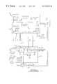
- FIG. 1is a block diagram showing a multimedia system employing the power management strategy of the present invention.
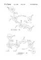
- FIG. 2is a state diagram showing state transitions of the system in FIG. 1 .
- FIG. 3is a state diagram showing monitoring of heartbeat messages during full-power operation.
- FIG. 4is a state diagram showing fault management during wake-up of the main application microprocessor.
- FIG. 5is a state diagram showing fault management during shutdown to the suspend-to-RAM state of the main application microprocessor.
- FIG. 6is a state diagram showing fault management during shutdown to the suspend-to-disk state of the main application microprocessor.
- a motherboard 10is connected to a video processor card 11 and a vehicle input/output processor (VIOP) board 12 .
- Motherboard 10includes a complex instruction set computing (CISC) processor 13 which may comprised of an Intel Celleron processor, for example.
- CISCcomplex instruction set computing
- a support chip set 14is connected to processor 13 and is adapted to function specifically with microprocessor 13 .
- Support chip set 14may be one or more integrated circuits and may preferably be comprised of north and south portions of an Intel Banister Bridge.
- Chip set 14provides interfaces between processor 13 and various other devices and provides local power management for processor 13 .
- Support chip set 14includes a DRAM memory controller for controlling a DRAM memory 15 .
- Chip set 14also includes interface controllers for a mass storage devices such as a hard drive 16 and a CD-ROM drive 17 .
- Processor 13is a main application processor and executes operating system software and application programs contained on hard drive 16 and/or CD-ROM drive 17 .
- a time of day (TOD) unit 18is connected to chip set 14 and keeps track of time of day in a conventional manner.
- a low quiescent current regulator that operates off of the vehicle battery(not shown) is preferably provided to maintain operation of TOD unit 18 even when power is off to motherboard 10 .
- Chip set 14receives several different regulated voltages from VIOP 12 as is described below. Chip set 14 helps control the regulated voltages to provide power to processor 13 and DRAM 15 according to its own, conventional power management strategy. Motherboard 10 may further include a core power supply 19 driven by chip set 14 to provide a regulated voltage at a value not being supplied by VIOP 12 .
- a super-input/output (I/O) interface 20is connected to chip set 14 and provides a serial communications port COM 1 which is connected to VIOP 12 .
- the serial communications linkcarries messages between processor 13 and VIOP 12 relating to power management and to input and output data and control signals.
- Motherboard 10includes other conventional components which are not shown such as a BIOS unit and standard bus interfaces such as ISA, PCI, and USB interfaces.
- Video card 11may be connected to a PCI expansion slot, for example.
- Video card 11includes a video output connected to a display 21 which is powered by an off-board regulator 22 under control of VIOP 12 .
- VIOP 12includes a reduced power microprocessor 25 which executes program instructions contained in a read-only memory (ROM) 26 , for example.
- Reduced power microprocessor 25may be comprised of a Motorola 68 HC 912 processor, for example, or other low power processor of the type often used on automotive applications.
- a principle job of processor 25is to control a power controller and regulator 27 which has a plurality of switched and unswitched regulated voltage outputs. For example, switched outputs of 3.3V, 5V, and 10V are provided along with an unswitched (i.e., continuous) supply of 3.3V.
- Each of these regulated voltagesis provided to main motherboard 10 and then distributed to various components which use them, including chip set 14 .
- These voltagesare used to operate microprocessor 13 , power memory 15 for refreshing and accessing memory contents, and for powering portions of chip set 14 itself.
- powermay be directly supplied to hard drive 16 , CD-ROM 17 and TOD unit 18 .
- Power controller and regulator 27may also provide regulated voltages to devices located remotely from motherboard 10 and VIOP 12 .
- a separate, remote modulemay include a GPS receiver and a wireless data transceiver receiving GPS power (GPS PWR) and transceiver power (XCVR PWR) from power controller and regulator 27 .
- GPS PWRGPS power
- XCVR PWRtransceiver power
- VIOP 12includes a physical interface 28 for providing a serial port connection for microprocessor 25 to communicate with the COM 1 port of motherboard 10 .
- microprocessor 25provides a power button signal in response to an on/off switch 30 controlled by the user to indicate when to place the multimedia system in an in-use condition, and a reset signal for causing the main application processor 13 to reboot.
- Chip set 14provides three distinct signals SUS A, SUS B, and SUS C, which identify the suspended power state in which the power management strategy of chip set 14 is operating.
- Microprocessor 25also receives a signal from an ignition switch 31 to identify whether the vehicle is in a powered state or an unpowered state. Based upon the state of ignition switch 31 and on/off switch 30 , microprocessor 25 and microprocessor 13 each determine an appropriate power state for main application processor 13 and chip set 14 . Depending upon the current state and next desired state of microprocessor 13 and chip set 14 , microprocessor 25 may merely verify that the correct state has been implemented by chip set 14 , it may command a different state over the serial communication link, or it may switch the state of power controller and regulator 27 to provide different regulated voltages to main motherboard 10 . Also based upon the state of various switches or other inputs, microprocessor 25 may control the switching on and off of off-board regulator 22 for powering display 21 as appropriate.
- a network interface 32is contained in VIOP 12 and is connected to microprocessor 25 .
- Network interface 32may be connected to a vehicle network for exchanging data and control signals between motherboard 13 and a vehicle communication or multiplex network (also using the serial communication link between motherboard 10 and VIOP 12 ).
- the multimedia systemPrior to application of any power, the multimedia system is in No Power state 40 . In No Power state 40 , main battery power is disconnected and all units are off. Once power is applied, the multimedia system transitions to a Sleep state 41 .
- Sleep state 41is characterized by the following conditions: ignition is off, the VIOP unit is asleep, the main microprocessor and chip set are off, the display is off, remote wireless and GPS units are off, CD-ROM unit is off, and display backlighting is off (backlighting refers to background lighting of an LCD display and is desirable to provide general panel lighting of a vehicle dashboard during low light conditions even though the unit itself is off).
- a lights-on conditiontriggers a transition to a Power Save state 42 in which the VIOP unit is awake and can control backlighting power to the display.
- a transitionis made to return to Sleep state 41 .
- Transitionmay be made to Sleep state 41 from any other state during a shutdown caused by an error or lock-up condition of the main microprocessor causing it to fail to respond to VIOP messages. In that case, the VIOP processor shuts down all switched power to main motherboard 10 thereby initiating Sleep state 41 .
- Power Save state 42is characterized by the following conditions: ignition is off, VIOP unit is awake, main application processor and chip set are asleep in a suspend-to-disk state (referred to as a D 3 state for an Intel Celleron chipset/ACPI spec), the display is off, wireless and GPS transceivers are off, CD-ROM unit is off, and display backlighting may or may not be on depending upon other vehicle settings (e.g., headlights).
- a transitionwill be made out of Power Save state 42 depending upon the status of the on/off power button on the multimedia unit itself. If the power button is off, then a transition is made to Standby+ state 43 . If the power button is on, then a transition is made to Full Power state 44 .
- Standby+ state 43is characterized by the following conditions: ignition is on, VIOP unit is awake, main processor and chip set are on, display is off, wireless data transceiver is off, GPS unit is on, CD-ROM unit is off, and backlighting of the display is dependent on other lamp states. While in Standby+ state 43 , a transition may be made to Full Power state 44 in response to the turning on of the power button, activity on any other button controls of the multimedia system as appropriate, or the insertion of a media such as a CD audio disc. If the ignition switch is turned off while in Standby+ state 43 , a transition is made to Standby state 45 .
- Standby state 45is characterized by the following conditions: ignition is off, VIOP unit is awake, the main processor and chip set are asleep in the suspend-to-RAM state (designated as state S 3 in the Intel Celleron power management strategy), display is off, wireless transceiver and GPS receiver are off, CD-ROM unit is off, and display backlighting depends upon vehicle lamps.
- a fairly low quiescent current consumption of about 100 mAmay be obtained. Although this current draw is fairly low, it is higher than can be maintained for extremely long periods in a vehicle which must rely on its main battery for starting the vehicle internal combustion engine.
- Standby state 45includes operating of the time of day timer in order to detect a predetermined period of time, after which a transition is made to Power Save state 42 .
- Power Save state 42the main processor and chip set switch to the suspend-to-disk condition and since the DRAM memory does not need to be continuously refreshed, the power consumption may drop to about 4 mA.
- the predetermined period of timeis about 24 hours. If the vehicle is restarted within 24 hours, the current state of memory will still be in DRAM and a much faster boot-up of the system can be achieved (a boot-up time of about one to two seconds as opposed to a boot-up time of from 6 to 10 seconds from the suspend-to-disk condition). If the ignition switch is turned on while in Standby state 45 , a transition is made to Standby+ state 43 or Full Power state 44 depending upon the position of the power button.
- the main microprocessor and chip setmay have many different suspend or low power states.
- the suspend-to-RAM and suspend-to-disk power statesare preferred to be used.
- S 3suspend-to-RAM
- an instant on and boot-up time of between 1 and 2 secondsis achieved.
- the DRAMis in a self refresh mode.
- the chip setis configured so that about 80% of the chip set is turned off.
- the north bridge SUSPEND wellis powered, the DRAM lines are set for self refresh mode, and the south bridge interrupt controller and power controller have power (i.e., RTC well and SUSPEND well) while the Pentium processor is off.
- the suspend-to-RAM statedraws between 50 and 70 mA of current and the state may be exited by pressing the power button while the ignition is on, by a reset signal from the VIOP, or by other programmed resume events.
- D 3In the suspend-to-disk (D 3 ) power state, an image or snapshot of the DRAM memory contents is stored to disk (preferably a compact flash drive).
- the north bridge of the chip setis powered down and the south bridge is mostly powered down except for the south bridge section that has power control (i.e., south bridge SUSPEND well and RTC well).
- Current drawis between 1 and 2 mA in this power state. Current draw results in part from the need to drive the SUS A, B, and C lines for giving the power state status of the main controller and chip set.
- the serial communications link between microprocessors 13 and 25carries various types of messages, such as input/output data and control signals for various peripheral devices.
- fault management and status messagesare communicated to permit reduced power microprocessor 25 to ensure proper operation of the multimedia system.
- the main application microprocessorbecomes “locked-up” or “frozen,” this is detected by the reduced power microprocessor and action can be taken to restore proper operation without requiring user intervention.
- the main application microprocessorassumes a power state other than the one required by the power management strategy, this is detected and, if not correctable, then the reduced power microprocessor avoids possible excessive current consumption by shutting off most power to the main application microprocessor.
- the fault management strategy of the present inventionemploys a status message (or “heartbeat” message) that is programmed to be sent periodically by the main application microprocessor to the reduced power microprocessor whenever the main application microprocessor is running (i.e., operating in the Full Power state or the Standby+ state).
- a status messageor “heartbeat” message
- the main application processoris programmed to generate a regular heartbeat message (e.g., every 5 seconds). If the reduced power microprocessor fails to receive an expected heartbeat message within this predetermined time, then the main application processor is assumed to have malfunctioned and corrective action is taken.
- the fault strategyAfter initiation of a boot-up of the main application processor, the fault strategy enters a state 50 wherein a waiting period is established within the reduced power microprocessor of 60 seconds. During this 60 second time period, a heartbeat message would be expected from the main application processor if boot-up to a normal running state is achieved. If, as expected, a heartbeat message is received during the 60 second time period, then a shorter waiting period of 5 seconds is established in a state 51 . If a heartbeat message is received during the shorter waiting period, then the fault strategy stays in state 51 with a reinitiation of the 5 second waiting period.
- a heartbeat messageis not detected by the reduced power microprocessor during the 5 second waiting period, then it enters state 52 and sends a reset signal to the main application processor to re-boot it. Then the reduced power microprocessor returns to state 50 to establish the 60 second waiting period.
- a heartbeat messageis not received during the 60 second time period in state 50 , then a series of resets followed by additional 60 second waiting periods are established in states 53 through 58 . If a heartbeat message is received while in states 54 , 56 , or 58 , then normal operation results in state 51 . If on the final try in state 58 no heartbeat message is received, then the regulated voltages supplied to the main motherboard by the VIOP power controller and regulator are cycled off and then back on in an attempt to recover proper operation of the main application microprocessor. Then the main application microprocessor attempts to restart or re-boot, and the fault strategy returns to state 50 .
- FIG. 4A portion of the fault strategy of the present invention active during an attempt to wake up the main application processor from a suspend-to-disk (OFF or D 3 ) condition or a suspend-to-RAM (SUSPEND or S 3 ) condition is shown in FIG. 4 .
- the main application microprocessoris in SUSPEND or OFF initially in state 60 .
- a transition to state 61is made in response to a wake-up command.
- a wake-up commandmay be a signal generated by any devices in the system such as a user control push button (e.g., power button), the vehicle ignition switch, or insertion of a media (e.g., CD-ROM, CD audio, or cassette tape).
- the reduced power microprocessormonitors these conditions and determines when existing conditions should wake the main application processor to its full-powered operating state and then generates the resume/wakeup command to the main application processor/motherboard. Then, in state 61 , it checks status lines SUS A, B, and C, to determine the power state of the main application processor. If these lines indicate a run state, then no further action is taken. However, if these lines indicate an OFF or SUSPEND state, then the reduced power microprocessor exercises its own wake-up sequence (i.e. resume event) to the main application processor/chipset in state 62 . The wake-up sequence/command (resume event) is retried up to 2 more times (after sufficient waiting periods) if the command is unsuccessful.
- the state of the vehicle ignitionis determined. If the ignition is off, then there should be no further consumption of current and the regulated voltages are turned off in state 63 . On the other hand, if the ignition is on then the regulated voltages are cycled off and back on in state 64 in an attempt to restore proper system operation. Then another wake-up sequence (resume event) is initiated and a return is made to state 61 .
- FIG. 5A portion of the fault strategy of the present invention active during an attempt to shutdown the main application processor to a suspend-to-RAM (SUSPEND or S 3 ) condition from a full-on condition is shown in FIG. 5 .
- Proper shutdown to the SUSPEND conditionis important in order to ensure limited current consumption when not in use and to limit boot-up time the next time the vehicle ignition switch is activated (i.e., within the next 24 hours).
- state 70the main application processor is in a full-on or run condition.
- a transition to state 71is made in response to a shutdown command.
- a shutdown commandmay be the signal generated by the vehicle ignition switch being turned to its off position.
- the reduced power microprocessormonitors the ignition switch, determines when the main application processor should be going to its suspended operating state, a generates a shutdown sequence to the main motherboard. Then, in state 71 , it checks status lines SUS A, B, and C, to determine the power state of the main application processor. If these lines indicate a SUSPEND state, then no further action is taken. However, if these lines indicate a run state, then the reduced power microprocessor transmits its own shutdown command over the serial communication link in state 72 .
- the shutdown commandis retried up to 2 more times (after sufficient waiting periods) if the initial command is unsuccessful. After the last try and if the SUSPEND condition is still not achieved, then a reset signal is sent to the main application microprocessor in state 73 . After reset, a further shutdown command is sent and the SUS A, B, and C lines are checked again in state 74 . If the SUSPEND condition is still not achieved, then the regulated voltages are powered off in state 75 .
- FIG. 6A portion of the fault strategy of the present invention active during an attempt to shutdown the main application processor to a suspend-to-disk (OFF or D 3 ) condition from a suspend-to-RAM condition is shown in FIG. 6 .
- Proper shutdown to the OFF conditionis important in order to ensure minimal to no current consumption during long term non-use at the expense of having a long boot-up time the next time the vehicle ignition switch is activated.
- the main application processoris in a suspend-to-RAM condition.
- Both the main application microprocessor and the reduced power microprocessordetect passage of a long duration time period (e.g., 24 hours).
- the time period measured by the reduced power microprocessoris slightly longer, so that if the main application microprocessor functions properly, it will perform the suspend-to-disk operation (e.g., transferring RAM contents to a compact flash drive) on its own.
- a transitionis made in state 81 where it checks status lines SUS A, B, and C, to determine the power state of the main application processor.
- the reduced power microprocessorinitiates a wake-up sequence (resume event) to the main application processor/chipset in state 82 so that a shutdown-to-disk command can be executed by the main application processor.
- Status lines SUS A, B, and Care checked in state 83 to verify that a full-on or run state has been entered. If the run state is achieved, then a suspend-to-disk (STD) command is transmitted in state 84 . Otherwise, the wake-up sequence (resume event) is retried up to 3 more times in state 85 (after sufficient waiting periods). After the last try and if the run condition is still not achieved, then regulated voltages are turned off to the main application microprocessor in state 86 .
Landscapes
- Engineering & Computer Science (AREA)
- Theoretical Computer Science (AREA)
- Physics & Mathematics (AREA)
- General Engineering & Computer Science (AREA)
- General Physics & Mathematics (AREA)
- Power Sources (AREA)
- Small-Scale Networks (AREA)
Abstract
Description
Claims (6)
Priority Applications (4)
| Application Number | Priority Date | Filing Date | Title |
|---|---|---|---|
| US09/353,684US6367022B1 (en) | 1999-07-14 | 1999-07-14 | Power management fault strategy for automotive multimedia system |
| EP00305907AEP1069495A2 (en) | 1999-07-14 | 2000-07-12 | Power management fault strategy for automotive multimedia system |
| JP2000214609AJP2001075684A (en) | 1999-07-14 | 2000-07-14 | Power abnormality managing method for multi-media system of automobile |
| US09/735,003US6944779B2 (en) | 1999-07-14 | 2000-12-11 | Power management fault strategy for automotive multimedia system |
Applications Claiming Priority (1)
| Application Number | Priority Date | Filing Date | Title |
|---|---|---|---|
| US09/353,684US6367022B1 (en) | 1999-07-14 | 1999-07-14 | Power management fault strategy for automotive multimedia system |
Related Child Applications (1)
| Application Number | Title | Priority Date | Filing Date |
|---|---|---|---|
| US09/735,003Continuation-In-PartUS6944779B2 (en) | 1999-07-14 | 2000-12-11 | Power management fault strategy for automotive multimedia system |
Publications (1)
| Publication Number | Publication Date |
|---|---|
| US6367022B1true US6367022B1 (en) | 2002-04-02 |
Family
ID=23390116
Family Applications (1)
| Application Number | Title | Priority Date | Filing Date |
|---|---|---|---|
| US09/353,684Expired - Fee RelatedUS6367022B1 (en) | 1999-07-14 | 1999-07-14 | Power management fault strategy for automotive multimedia system |
Country Status (3)
| Country | Link |
|---|---|
| US (1) | US6367022B1 (en) |
| EP (1) | EP1069495A2 (en) |
| JP (1) | JP2001075684A (en) |
Cited By (37)
| Publication number | Priority date | Publication date | Assignee | Title |
|---|---|---|---|---|
| US20030051177A1 (en)* | 2001-09-12 | 2003-03-13 | Kwanghoi Koo | Method and apparatus for system power control through sensing peripheral power consumption |
| US20030084358A1 (en)* | 2001-10-31 | 2003-05-01 | Bresniker Kirk M. | System and method for intelligent control of power consumption of distributed services during periods of reduced load |
| US20030084359A1 (en)* | 2001-10-31 | 2003-05-01 | Bresniker Kirk M. | System and method for intelligent control of power consumption of distributed services during periods when power consumption must be reduced |
| US20030135767A1 (en)* | 2002-01-11 | 2003-07-17 | International Business Machines Corporation | System and method for co-operative thermal management of electronic devices within a common housing |
| US6598168B1 (en)* | 2000-05-09 | 2003-07-22 | Power Digital Communications Co. Ltd | Computer auto shut-off control method |
| US20040039951A1 (en)* | 2002-08-09 | 2004-02-26 | Aisin Aw Co., Ltd. | Power management system for a communication device |
| US20040078607A1 (en)* | 2002-10-18 | 2004-04-22 | Culture.Com Technology (Macau) Ltd. | Energy-saving electronic device and energy-saving method for use with the same |
| US20050250557A1 (en)* | 2004-05-10 | 2005-11-10 | Dialog Semiconductor Gmbh | Micro-controller controlled power management chip |
| US20060111062A1 (en)* | 2004-11-19 | 2006-05-25 | Ken Cunningham | Adaptive radio frequency wakeup detection |
| US7132822B1 (en) | 2006-02-28 | 2006-11-07 | Watlow Electric Manufacturing Company | Multi-processor restart stabilization system and method |
| US20060277555A1 (en)* | 2005-06-03 | 2006-12-07 | Damian Howard | Portable device interfacing |
| CN100349097C (en)* | 2004-02-25 | 2007-11-14 | 英特维数位科技股份有限公司 | Power Management Architecture and Method for Computer System |
| US20080059016A1 (en)* | 2006-08-31 | 2008-03-06 | Mayhew William R | Distributed arithmetic logic unit security check |
| US20080147308A1 (en)* | 2006-12-18 | 2008-06-19 | Damian Howard | Integrating Navigation Systems |
| US20080310337A1 (en)* | 2007-06-18 | 2008-12-18 | Gainspan, Inc. | Periodic heartbeat communication between devices and a control point |
| US20090130884A1 (en)* | 2007-11-15 | 2009-05-21 | Bose Corporation | Portable device interfacing |
| US20090157960A1 (en)* | 2007-12-12 | 2009-06-18 | Canon Kabushiki Kaisha | Information processing apparatus and start-up method of the apparatus |
| US20090172469A1 (en)* | 2007-12-27 | 2009-07-02 | Huawei Technologies Co., Ltd. | Method, apparatus, logic device and storage system for power-fail protection |
| US20090318119A1 (en)* | 2008-06-19 | 2009-12-24 | Basir Otman A | Communication system with voice mail access and call by spelling functionality |
| US20100023204A1 (en)* | 2008-07-24 | 2010-01-28 | Basir Otman A | Power management system |
| US20100149716A1 (en)* | 2008-12-11 | 2010-06-17 | Caterpillar Inc. | System and method for reducing quiescent power draw and machine using same |
| US20100305807A1 (en)* | 2009-05-28 | 2010-12-02 | Basir Otman A | Communication system with personal information management and remote vehicle monitoring and control features |
| US20110034144A1 (en)* | 2007-12-24 | 2011-02-10 | Gang Yang | System and method for managing communication of a moveable entity for energy conservation |
| US20110121991A1 (en)* | 2009-11-25 | 2011-05-26 | Basir Otman A | Vehicle to vehicle chatting and communication system |
| US20110179096A1 (en)* | 2010-01-15 | 2011-07-21 | Galloway Curtis C | Specialized Network Fileserver |
| US20110239020A1 (en)* | 2010-03-29 | 2011-09-29 | Thomas Sujith | Power management based on automatic workload detection |
| US20130045683A1 (en)* | 2011-08-15 | 2013-02-21 | Adam James Wang | Vehicle wireless hub |
| US20130138939A1 (en)* | 2011-11-25 | 2013-05-30 | Inventec Corporation | Method for processing booting errors |
| US20130254468A1 (en)* | 2012-03-23 | 2013-09-26 | Suzuki Motor Corporation | Storage control device, storage control method and program |
| US20130254586A1 (en)* | 2012-03-20 | 2013-09-26 | Research In Motion Limited | Fault recovery |
| DE102012017386A1 (en)* | 2012-09-01 | 2014-05-15 | Volkswagen Aktiengesellschaft | A method of monitoring a device connected to a communication channel |
| US8856009B2 (en) | 2008-03-25 | 2014-10-07 | Intelligent Mechatronic Systems Inc. | Multi-participant, mixed-initiative voice interaction system |
| US20150239351A1 (en)* | 2014-02-26 | 2015-08-27 | Denso Corporation | Electronic control device |
| US9930158B2 (en) | 2005-06-13 | 2018-03-27 | Ridetones, Inc. | Vehicle immersive communication system |
| US9976865B2 (en) | 2006-07-28 | 2018-05-22 | Ridetones, Inc. | Vehicle communication system with navigation |
| US11786146B1 (en) | 2012-09-25 | 2023-10-17 | Micro Mobio Corporation | Wireless hub system and method |
| US12138041B1 (en) | 2012-09-25 | 2024-11-12 | Micro Mobio Corporation | Mobile device case with satellite communication capability |
Families Citing this family (11)
| Publication number | Priority date | Publication date | Assignee | Title |
|---|---|---|---|---|
| US6944779B2 (en) | 1999-07-14 | 2005-09-13 | Visteon Global Technologies, Inc. | Power management fault strategy for automotive multimedia system |
| DE10201958A1 (en)* | 2002-01-19 | 2003-07-31 | Bosch Gmbh Robert | Method for monitoring the operational readiness of at least one memory element assigned to an electronic unit |
| US7210009B2 (en) | 2003-09-04 | 2007-04-24 | Advanced Micro Devices, Inc. | Computer system employing a trusted execution environment including a memory controller configured to clear memory |
| CN100530042C (en)* | 2006-12-21 | 2009-08-19 | 技嘉科技股份有限公司 | Mainboard and power converter for computer on vehicle |
| EP1950642A1 (en)* | 2007-01-26 | 2008-07-30 | Giga-Byte Technology Co., Ltd. | Apparatus and method for energizing a computer in a vehicle |
| US9411704B2 (en) | 2013-11-20 | 2016-08-09 | Fujitsu Technology Solutions Intellectual Property Gmbh | Computer systems and methods of detecting AC failure |
| TW201525668A (en)* | 2013-12-24 | 2015-07-01 | Alpha Networks Inc | Electronic device capable of automatically resetting and automatic resetting method thereof |
| EP2924538B1 (en) | 2014-03-25 | 2020-06-17 | Fujitsu Technology Solutions Intellectual Property GmbH | Computer system and method for its operation |
| CN107346129B (en)* | 2016-05-06 | 2020-08-21 | 大陆汽车电子(长春)有限公司 | Vehicle body controller and power-off emergency processing method thereof |
| CN113169907B (en)* | 2018-06-08 | 2022-06-07 | 住友电装株式会社 | Communication apparatus and control method |
| JP7147525B2 (en)* | 2018-06-08 | 2022-10-05 | 住友電装株式会社 | Communication device and control method |
Citations (7)
| Publication number | Priority date | Publication date | Assignee | Title |
|---|---|---|---|---|
| US4698748A (en) | 1983-10-07 | 1987-10-06 | Essex Group, Inc. | Power-conserving control system for turning-off the power and the clocking for data transactions upon certain system inactivity |
| US5560022A (en) | 1994-07-19 | 1996-09-24 | Intel Corporation | Power management coordinator system and interface |
| US5595121A (en)* | 1994-04-15 | 1997-01-21 | The Walt Disney Company | Amusement ride and self-propelled vehicle therefor |
| US5680308A (en) | 1995-05-01 | 1997-10-21 | Borg-Warner Automotive, Inc. | Automobile transfer case system and control circuit therefor |
| US5907194A (en)* | 1996-07-15 | 1999-05-25 | Robert Bosch Gmbh | Device for supplying voltage in a motor vehicle including two batteries and having improved reliability |
| US5928292A (en)* | 1986-10-03 | 1999-07-27 | Norand Corporation | Vehicular data system for communicating with remote host |
| US6181118B1 (en)* | 1999-06-24 | 2001-01-30 | Analog Devices, Inc. | Control circuit for controlling a semi-conductor switch for selectively outputting an output voltage at two voltage levels |
Family Cites Families (1)
| Publication number | Priority date | Publication date | Assignee | Title |
|---|---|---|---|---|
| JP3097580B2 (en)* | 1996-12-18 | 2000-10-10 | 株式会社デンソー | Electronic control unit |
- 1999
- 1999-07-14USUS09/353,684patent/US6367022B1/ennot_activeExpired - Fee Related
- 2000
- 2000-07-12EPEP00305907Apatent/EP1069495A2/ennot_activeWithdrawn
- 2000-07-14JPJP2000214609Apatent/JP2001075684A/enactivePending
Patent Citations (7)
| Publication number | Priority date | Publication date | Assignee | Title |
|---|---|---|---|---|
| US4698748A (en) | 1983-10-07 | 1987-10-06 | Essex Group, Inc. | Power-conserving control system for turning-off the power and the clocking for data transactions upon certain system inactivity |
| US5928292A (en)* | 1986-10-03 | 1999-07-27 | Norand Corporation | Vehicular data system for communicating with remote host |
| US5595121A (en)* | 1994-04-15 | 1997-01-21 | The Walt Disney Company | Amusement ride and self-propelled vehicle therefor |
| US5560022A (en) | 1994-07-19 | 1996-09-24 | Intel Corporation | Power management coordinator system and interface |
| US5680308A (en) | 1995-05-01 | 1997-10-21 | Borg-Warner Automotive, Inc. | Automobile transfer case system and control circuit therefor |
| US5907194A (en)* | 1996-07-15 | 1999-05-25 | Robert Bosch Gmbh | Device for supplying voltage in a motor vehicle including two batteries and having improved reliability |
| US6181118B1 (en)* | 1999-06-24 | 2001-01-30 | Analog Devices, Inc. | Control circuit for controlling a semi-conductor switch for selectively outputting an output voltage at two voltage levels |
Non-Patent Citations (1)
| Title |
|---|
| Entertainment and information merge in the automobile, William C. Spelman, Delco Electronics, Co., IEEE Vehicular Technology Society News, Feb., 1996, pp. 49-55. |
Cited By (69)
| Publication number | Priority date | Publication date | Assignee | Title |
|---|---|---|---|---|
| US6598168B1 (en)* | 2000-05-09 | 2003-07-22 | Power Digital Communications Co. Ltd | Computer auto shut-off control method |
| US20060136759A1 (en)* | 2001-09-12 | 2006-06-22 | Kwanghoi Koo | Method and apparatus for system power control through sensing peripheral power consumption |
| US20030051177A1 (en)* | 2001-09-12 | 2003-03-13 | Kwanghoi Koo | Method and apparatus for system power control through sensing peripheral power consumption |
| US7574614B2 (en)* | 2001-09-12 | 2009-08-11 | Apple Inc. | Method and apparatus for changing a digital processing system power consumption state by sensing peripheral power consumption |
| US6981161B2 (en)* | 2001-09-12 | 2005-12-27 | Apple Computer, Inc. | Method and apparatus for changing a digital processing system power consumption state by sensing peripheral power consumption |
| US20030084358A1 (en)* | 2001-10-31 | 2003-05-01 | Bresniker Kirk M. | System and method for intelligent control of power consumption of distributed services during periods of reduced load |
| US20030084359A1 (en)* | 2001-10-31 | 2003-05-01 | Bresniker Kirk M. | System and method for intelligent control of power consumption of distributed services during periods when power consumption must be reduced |
| US7203846B2 (en)* | 2001-10-31 | 2007-04-10 | Hewlett-Packard Development Company, Lp. | System and method for intelligent control of power consumption of distributed services during periods of reduced load |
| US7043650B2 (en)* | 2001-10-31 | 2006-05-09 | Hewlett-Packard Development Company, L.P. | System and method for intelligent control of power consumption of distributed services during periods when power consumption must be reduced |
| US20030135767A1 (en)* | 2002-01-11 | 2003-07-17 | International Business Machines Corporation | System and method for co-operative thermal management of electronic devices within a common housing |
| US6934864B2 (en)* | 2002-01-11 | 2005-08-23 | International Business Machines Corporation | System and method for co-operative thermal management of electronic devices within a common housing |
| US20040039951A1 (en)* | 2002-08-09 | 2004-02-26 | Aisin Aw Co., Ltd. | Power management system for a communication device |
| US7814353B2 (en) | 2002-08-09 | 2010-10-12 | Aisin Aw Co., Ltd. | Power management system for a communication device |
| US20070016813A1 (en)* | 2002-08-09 | 2007-01-18 | Aisin Aw Co., Ltd. | Power management system for a communication device |
| US20040078607A1 (en)* | 2002-10-18 | 2004-04-22 | Culture.Com Technology (Macau) Ltd. | Energy-saving electronic device and energy-saving method for use with the same |
| CN100349097C (en)* | 2004-02-25 | 2007-11-14 | 英特维数位科技股份有限公司 | Power Management Architecture and Method for Computer System |
| US7684833B2 (en)* | 2004-05-10 | 2010-03-23 | Dialog Semiconductor Gmbh | Micro-controller controlled power management chip |
| US20050250557A1 (en)* | 2004-05-10 | 2005-11-10 | Dialog Semiconductor Gmbh | Micro-controller controlled power management chip |
| US20060111062A1 (en)* | 2004-11-19 | 2006-05-25 | Ken Cunningham | Adaptive radio frequency wakeup detection |
| US7286859B2 (en) | 2004-11-19 | 2007-10-23 | Lear Corporation | Adaptive radio frequency wakeup detection |
| US20060277555A1 (en)* | 2005-06-03 | 2006-12-07 | Damian Howard | Portable device interfacing |
| US9930158B2 (en) | 2005-06-13 | 2018-03-27 | Ridetones, Inc. | Vehicle immersive communication system |
| US7132822B1 (en) | 2006-02-28 | 2006-11-07 | Watlow Electric Manufacturing Company | Multi-processor restart stabilization system and method |
| US9976865B2 (en) | 2006-07-28 | 2018-05-22 | Ridetones, Inc. | Vehicle communication system with navigation |
| US20080059016A1 (en)* | 2006-08-31 | 2008-03-06 | Mayhew William R | Distributed arithmetic logic unit security check |
| US7933696B2 (en)* | 2006-08-31 | 2011-04-26 | GM Global Technology Operations LLC | Distributed arithmetic logic unit security check |
| US20080147308A1 (en)* | 2006-12-18 | 2008-06-19 | Damian Howard | Integrating Navigation Systems |
| US20080310337A1 (en)* | 2007-06-18 | 2008-12-18 | Gainspan, Inc. | Periodic heartbeat communication between devices and a control point |
| US7931505B2 (en) | 2007-11-15 | 2011-04-26 | Bose Corporation | Portable device interfacing |
| US20090130884A1 (en)* | 2007-11-15 | 2009-05-21 | Bose Corporation | Portable device interfacing |
| US8862822B2 (en)* | 2007-12-12 | 2014-10-14 | Canon Kabushiki Kaisha | Information processing apparatus and start-up method of the apparatus |
| US20090157960A1 (en)* | 2007-12-12 | 2009-06-18 | Canon Kabushiki Kaisha | Information processing apparatus and start-up method of the apparatus |
| US8626107B2 (en)* | 2007-12-24 | 2014-01-07 | Caterpillar Inc. | System and method for managing communication of a moveable entity for energy conservation |
| US20110034144A1 (en)* | 2007-12-24 | 2011-02-10 | Gang Yang | System and method for managing communication of a moveable entity for energy conservation |
| US20090172469A1 (en)* | 2007-12-27 | 2009-07-02 | Huawei Technologies Co., Ltd. | Method, apparatus, logic device and storage system for power-fail protection |
| US8856009B2 (en) | 2008-03-25 | 2014-10-07 | Intelligent Mechatronic Systems Inc. | Multi-participant, mixed-initiative voice interaction system |
| US20090318119A1 (en)* | 2008-06-19 | 2009-12-24 | Basir Otman A | Communication system with voice mail access and call by spelling functionality |
| US8838075B2 (en) | 2008-06-19 | 2014-09-16 | Intelligent Mechatronic Systems Inc. | Communication system with voice mail access and call by spelling functionality |
| US9652023B2 (en)* | 2008-07-24 | 2017-05-16 | Intelligent Mechatronic Systems Inc. | Power management system |
| US20100023204A1 (en)* | 2008-07-24 | 2010-01-28 | Basir Otman A | Power management system |
| US20100149716A1 (en)* | 2008-12-11 | 2010-06-17 | Caterpillar Inc. | System and method for reducing quiescent power draw and machine using same |
| US7977813B2 (en) | 2008-12-11 | 2011-07-12 | Caterpillar Inc. | System and method for reducing quiescent power draw and machine using same |
| US20100305807A1 (en)* | 2009-05-28 | 2010-12-02 | Basir Otman A | Communication system with personal information management and remote vehicle monitoring and control features |
| US8577543B2 (en) | 2009-05-28 | 2013-11-05 | Intelligent Mechatronic Systems Inc. | Communication system with personal information management and remote vehicle monitoring and control features |
| US9978272B2 (en) | 2009-11-25 | 2018-05-22 | Ridetones, Inc | Vehicle to vehicle chatting and communication system |
| US20110121991A1 (en)* | 2009-11-25 | 2011-05-26 | Basir Otman A | Vehicle to vehicle chatting and communication system |
| US10091203B2 (en) | 2010-01-15 | 2018-10-02 | Apple Inc. | Specialized network fileserver |
| US10305910B2 (en) | 2010-01-15 | 2019-05-28 | Apple Inc. | Accessing specialized fileserver |
| US20110179083A1 (en)* | 2010-01-15 | 2011-07-21 | Galloway Curtis C | Accessing Specialized Fileserver |
| US9052919B2 (en) | 2010-01-15 | 2015-06-09 | Apple Inc. | Specialized network fileserver |
| US20110179096A1 (en)* | 2010-01-15 | 2011-07-21 | Galloway Curtis C | Specialized Network Fileserver |
| TWI453598B (en)* | 2010-01-15 | 2014-09-21 | Apple Inc | Accessing specialized fileserver |
| US20110239020A1 (en)* | 2010-03-29 | 2011-09-29 | Thomas Sujith | Power management based on automatic workload detection |
| US8335935B2 (en)* | 2010-03-29 | 2012-12-18 | Intel Corporation | Power management based on automatic workload detection |
| US9866277B2 (en)* | 2011-08-15 | 2018-01-09 | Adam James Wang | Vehicle wireless hub |
| US20130045683A1 (en)* | 2011-08-15 | 2013-02-21 | Adam James Wang | Vehicle wireless hub |
| US8726088B2 (en)* | 2011-11-25 | 2014-05-13 | Inventec Corporation | Method for processing booting errors |
| US20130138939A1 (en)* | 2011-11-25 | 2013-05-30 | Inventec Corporation | Method for processing booting errors |
| US9026842B2 (en)* | 2012-03-20 | 2015-05-05 | Blackberry Limited | Selective fault recovery of subsystems |
| US20130254586A1 (en)* | 2012-03-20 | 2013-09-26 | Research In Motion Limited | Fault recovery |
| US9400742B2 (en)* | 2012-03-23 | 2016-07-26 | Suzuki Motor Corporation | Storage control device, storage control method and program |
| US20130254468A1 (en)* | 2012-03-23 | 2013-09-26 | Suzuki Motor Corporation | Storage control device, storage control method and program |
| US9817741B2 (en) | 2012-09-01 | 2017-11-14 | Volkswagen Ag | Method for monitoring an apparatus connected to a communication channel |
| DE102012017386A1 (en)* | 2012-09-01 | 2014-05-15 | Volkswagen Aktiengesellschaft | A method of monitoring a device connected to a communication channel |
| DE102012017386B4 (en)* | 2012-09-01 | 2020-10-15 | Volkswagen Aktiengesellschaft | Method of monitoring a device connected to a communication channel |
| US11786146B1 (en) | 2012-09-25 | 2023-10-17 | Micro Mobio Corporation | Wireless hub system and method |
| US12138041B1 (en) | 2012-09-25 | 2024-11-12 | Micro Mobio Corporation | Mobile device case with satellite communication capability |
| US9796275B2 (en)* | 2014-02-26 | 2017-10-24 | Denso Corporation | Electronic control device |
| US20150239351A1 (en)* | 2014-02-26 | 2015-08-27 | Denso Corporation | Electronic control device |
Also Published As
| Publication number | Publication date |
|---|---|
| JP2001075684A (en) | 2001-03-23 |
| EP1069495A2 (en) | 2001-01-17 |
Similar Documents
| Publication | Publication Date | Title |
|---|---|---|
| US6367022B1 (en) | Power management fault strategy for automotive multimedia system | |
| US6944779B2 (en) | Power management fault strategy for automotive multimedia system | |
| US6393573B1 (en) | Power management for automotive multimedia system | |
| EP1083475B1 (en) | Power management in automotive computer systems during engine ignition | |
| US7430673B2 (en) | Power management system for computing platform | |
| US7685466B2 (en) | BIOS for saving and restoring operational state in the absence of AC power | |
| US20150019895A1 (en) | Information processing apparatus and judging method | |
| CN104246655A (en) | Information processing device, information processing method, and program | |
| JPH10228340A (en) | Electronic device | |
| US20030070065A1 (en) | Suspending to nonvolatile storage | |
| CN115756622B (en) | Chip control method and chip | |
| JPH11288334A (en) | Method and apparatus for powering down a computer system | |
| US20070150760A1 (en) | Reducing the amount of memory contents saved to non-volatile storage | |
| US20030065861A1 (en) | Dual system masters | |
| US6477655B1 (en) | System and method to set PME—status bit and wake up the system, and selectively load device driver by searching who set the bit without requiring clock | |
| JP3960800B2 (en) | Method of operating a processor-based system for a vehicle | |
| US6065125A (en) | SMM power management circuits, systems, and methods | |
| CN118897696A (en) | SOC chip sleep method, device and vehicle | |
| CN117377044A (en) | Control method, device, equipment and storage medium of network management ECU | |
| JP2000020182A (en) | Power management method | |
| US20110231679A1 (en) | Energy saving device | |
| CN223140138U (en) | Device for controlling the sleep mode of a system | |
| CN113650498B (en) | Power-on method and device of electric vehicle, electric vehicle and storage medium | |
| KR102685980B1 (en) | A power saving apparatus and method of a computer system by global power control manager | |
| JPH0588790A (en) | Power source control system |
Legal Events
| Date | Code | Title | Description |
|---|---|---|---|
| AS | Assignment | Owner name:FORD MOTOR COMPANY A MICHIGAN CORPORATION, MICHIGA Free format text:ASSIGNMENT OF ASSIGNORS INTEREST;ASSIGNORS:GILLESPIE, DOUGLAS BRIAN;KONSTANTINE, JOHN FRANK;REEL/FRAME:010108/0262;SIGNING DATES FROM 19990709 TO 19990712 | |
| AS | Assignment | Owner name:VISTEON GLOBAL TECHNOLOGIES, INC., MICHIGAN Free format text:ASSIGNMENT OF ASSIGNORS INTEREST;ASSIGNOR:FORD MOTOR COMPANY;REEL/FRAME:010968/0220 Effective date:20000615 | |
| FEPP | Fee payment procedure | Free format text:PAYOR NUMBER ASSIGNED (ORIGINAL EVENT CODE: ASPN); ENTITY STATUS OF PATENT OWNER: LARGE ENTITY | |
| FPAY | Fee payment | Year of fee payment:4 | |
| AS | Assignment | Owner name:JPMORGAN CHASE BANK, N.A., AS ADMINISTRATIVE AGENT Free format text:SECURITY AGREEMENT;ASSIGNOR:VISTEON GLOBAL TECHNOLOGIES, INC.;REEL/FRAME:020497/0733 Effective date:20060613 | |
| AS | Assignment | Owner name:JPMORGAN CHASE BANK, TEXAS Free format text:SECURITY INTEREST;ASSIGNOR:VISTEON GLOBAL TECHNOLOGIES, INC.;REEL/FRAME:022368/0001 Effective date:20060814 Owner name:JPMORGAN CHASE BANK,TEXAS Free format text:SECURITY INTEREST;ASSIGNOR:VISTEON GLOBAL TECHNOLOGIES, INC.;REEL/FRAME:022368/0001 Effective date:20060814 | |
| AS | Assignment | Owner name:WILMINGTON TRUST FSB, AS ADMINISTRATIVE AGENT, MIN Free format text:ASSIGNMENT OF SECURITY INTEREST IN PATENTS;ASSIGNOR:JPMORGAN CHASE BANK, N.A., AS ADMINISTRATIVE AGENT;REEL/FRAME:022575/0186 Effective date:20090415 Owner name:WILMINGTON TRUST FSB, AS ADMINISTRATIVE AGENT,MINN Free format text:ASSIGNMENT OF SECURITY INTEREST IN PATENTS;ASSIGNOR:JPMORGAN CHASE BANK, N.A., AS ADMINISTRATIVE AGENT;REEL/FRAME:022575/0186 Effective date:20090415 | |
| AS | Assignment | Owner name:THE BANK OF NEW YORK MELLON, AS ADMINISTRATIVE AGE Free format text:ASSIGNMENT OF PATENT SECURITY INTEREST;ASSIGNOR:JPMORGAN CHASE BANK, N.A., A NATIONAL BANKING ASSOCIATION;REEL/FRAME:022974/0057 Effective date:20090715 | |
| REMI | Maintenance fee reminder mailed | ||
| LAPS | Lapse for failure to pay maintenance fees | ||
| LAPS | Lapse for failure to pay maintenance fees | Free format text:PATENT EXPIRED FOR FAILURE TO PAY MAINTENANCE FEES (ORIGINAL EVENT CODE: EXP.); ENTITY STATUS OF PATENT OWNER: LARGE ENTITY | |
| STCH | Information on status: patent discontinuation | Free format text:PATENT EXPIRED DUE TO NONPAYMENT OF MAINTENANCE FEES UNDER 37 CFR 1.362 | |
| FP | Lapsed due to failure to pay maintenance fee | Effective date:20100402 | |
| AS | Assignment | Owner name:VISTEON GLOBAL TECHNOLOGIES, INC., MICHIGAN Free format text:RELEASE BY SECURED PARTY AGAINST SECURITY INTEREST IN PATENTS RECORDED AT REEL 022974 FRAME 0057;ASSIGNOR:THE BANK OF NEW YORK MELLON;REEL/FRAME:025095/0711 Effective date:20101001 | |
| AS | Assignment | Owner name:VISTEON GLOBAL TECHNOLOGIES, INC., MICHIGAN Free format text:RELEASE BY SECURED PARTY AGAINST SECURITY INTEREST IN PATENTS RECORDED AT REEL 022575 FRAME 0186;ASSIGNOR:WILMINGTON TRUST FSB, AS ADMINISTRATIVE AGENT;REEL/FRAME:025105/0201 Effective date:20101001 | |
| AS | Assignment | Owner name:MORGAN STANLEY SENIOR FUNDING, INC., AS AGENT, NEW Free format text:SECURITY AGREEMENT (REVOLVER);ASSIGNORS:VISTEON CORPORATION;VC AVIATION SERVICES, LLC;VISTEON ELECTRONICS CORPORATION;AND OTHERS;REEL/FRAME:025238/0298 Effective date:20101001 Owner name:MORGAN STANLEY SENIOR FUNDING, INC., AS AGENT, NEW Free format text:SECURITY AGREEMENT;ASSIGNORS:VISTEON CORPORATION;VC AVIATION SERVICES, LLC;VISTEON ELECTRONICS CORPORATION;AND OTHERS;REEL/FRAME:025241/0317 Effective date:20101007 | |
| AS | Assignment | Owner name:VISTEON INTERNATIONAL HOLDINGS, INC., MICHIGAN Free format text:RELEASE BY SECURED PARTY AGAINST SECURITY INTEREST IN PATENTS ON REEL 025241 FRAME 0317;ASSIGNOR:MORGAN STANLEY SENIOR FUNDING, INC.;REEL/FRAME:026178/0412 Effective date:20110406 Owner name:VISTEON EUROPEAN HOLDING, INC., MICHIGAN Free format text:RELEASE BY SECURED PARTY AGAINST SECURITY INTEREST IN PATENTS ON REEL 025241 FRAME 0317;ASSIGNOR:MORGAN STANLEY SENIOR FUNDING, INC.;REEL/FRAME:026178/0412 Effective date:20110406 Owner name:VISTEON GLOBAL TREASURY, INC., MICHIGAN Free format text:RELEASE BY SECURED PARTY AGAINST SECURITY INTEREST IN PATENTS ON REEL 025241 FRAME 0317;ASSIGNOR:MORGAN STANLEY SENIOR FUNDING, INC.;REEL/FRAME:026178/0412 Effective date:20110406 Owner name:VISTEON CORPORATION, MICHIGAN Free format text:RELEASE BY SECURED PARTY AGAINST SECURITY INTEREST IN PATENTS ON REEL 025241 FRAME 0317;ASSIGNOR:MORGAN STANLEY SENIOR FUNDING, INC.;REEL/FRAME:026178/0412 Effective date:20110406 Owner name:VC AVIATION SERVICES, LLC, MICHIGAN Free format text:RELEASE BY SECURED PARTY AGAINST SECURITY INTEREST IN PATENTS ON REEL 025241 FRAME 0317;ASSIGNOR:MORGAN STANLEY SENIOR FUNDING, INC.;REEL/FRAME:026178/0412 Effective date:20110406 Owner name:VISTEON GLOBAL TECHNOLOGIES, INC., MICHIGAN Free format text:RELEASE BY SECURED PARTY AGAINST SECURITY INTEREST IN PATENTS ON REEL 025241 FRAME 0317;ASSIGNOR:MORGAN STANLEY SENIOR FUNDING, INC.;REEL/FRAME:026178/0412 Effective date:20110406 Owner name:VISTEON INTERNATIONAL BUSINESS DEVELOPMENT, INC., Free format text:RELEASE BY SECURED PARTY AGAINST SECURITY INTEREST IN PATENTS ON REEL 025241 FRAME 0317;ASSIGNOR:MORGAN STANLEY SENIOR FUNDING, INC.;REEL/FRAME:026178/0412 Effective date:20110406 Owner name:VISTEON SYSTEMS, LLC, MICHIGAN Free format text:RELEASE BY SECURED PARTY AGAINST SECURITY INTEREST IN PATENTS ON REEL 025241 FRAME 0317;ASSIGNOR:MORGAN STANLEY SENIOR FUNDING, INC.;REEL/FRAME:026178/0412 Effective date:20110406 Owner name:VISTEON ELECTRONICS CORPORATION, MICHIGAN Free format text:RELEASE BY SECURED PARTY AGAINST SECURITY INTEREST IN PATENTS ON REEL 025241 FRAME 0317;ASSIGNOR:MORGAN STANLEY SENIOR FUNDING, INC.;REEL/FRAME:026178/0412 Effective date:20110406 | |
| AS | Assignment | Owner name:VISTEON INTERNATIONAL BUSINESS DEVELOPMENT, INC., Free format text:RELEASE OF SECURITY INTEREST IN INTELLECTUAL PROPERTY;ASSIGNOR:MORGAN STANLEY SENIOR FUNDING, INC.;REEL/FRAME:033107/0717 Effective date:20140409 Owner name:VISTEON EUROPEAN HOLDINGS, INC., MICHIGAN Free format text:RELEASE OF SECURITY INTEREST IN INTELLECTUAL PROPERTY;ASSIGNOR:MORGAN STANLEY SENIOR FUNDING, INC.;REEL/FRAME:033107/0717 Effective date:20140409 Owner name:VISTEON SYSTEMS, LLC, MICHIGAN Free format text:RELEASE OF SECURITY INTEREST IN INTELLECTUAL PROPERTY;ASSIGNOR:MORGAN STANLEY SENIOR FUNDING, INC.;REEL/FRAME:033107/0717 Effective date:20140409 Owner name:VC AVIATION SERVICES, LLC, MICHIGAN Free format text:RELEASE OF SECURITY INTEREST IN INTELLECTUAL PROPERTY;ASSIGNOR:MORGAN STANLEY SENIOR FUNDING, INC.;REEL/FRAME:033107/0717 Effective date:20140409 Owner name:VISTEON GLOBAL TREASURY, INC., MICHIGAN Free format text:RELEASE OF SECURITY INTEREST IN INTELLECTUAL PROPERTY;ASSIGNOR:MORGAN STANLEY SENIOR FUNDING, INC.;REEL/FRAME:033107/0717 Effective date:20140409 Owner name:VISTEON ELECTRONICS CORPORATION, MICHIGAN Free format text:RELEASE OF SECURITY INTEREST IN INTELLECTUAL PROPERTY;ASSIGNOR:MORGAN STANLEY SENIOR FUNDING, INC.;REEL/FRAME:033107/0717 Effective date:20140409 Owner name:VISTEON CORPORATION, MICHIGAN Free format text:RELEASE OF SECURITY INTEREST IN INTELLECTUAL PROPERTY;ASSIGNOR:MORGAN STANLEY SENIOR FUNDING, INC.;REEL/FRAME:033107/0717 Effective date:20140409 Owner name:VISTEON GLOBAL TECHNOLOGIES, INC., MICHIGAN Free format text:RELEASE OF SECURITY INTEREST IN INTELLECTUAL PROPERTY;ASSIGNOR:MORGAN STANLEY SENIOR FUNDING, INC.;REEL/FRAME:033107/0717 Effective date:20140409 Owner name:VISTEON INTERNATIONAL HOLDINGS, INC., MICHIGAN Free format text:RELEASE OF SECURITY INTEREST IN INTELLECTUAL PROPERTY;ASSIGNOR:MORGAN STANLEY SENIOR FUNDING, INC.;REEL/FRAME:033107/0717 Effective date:20140409 |