US6366051B1 - System for automatically charging the battery of a remote transmitter for use in a vehicle security system - Google Patents
System for automatically charging the battery of a remote transmitter for use in a vehicle security systemDownload PDFInfo
- Publication number
- US6366051B1 US6366051B1US09/924,284US92428401AUS6366051B1US 6366051 B1US6366051 B1US 6366051B1US 92428401 AUS92428401 AUS 92428401AUS 6366051 B1US6366051 B1US 6366051B1
- Authority
- US
- United States
- Prior art keywords
- charging
- battery
- signal
- circuit
- fully charged
- Prior art date
- Legal status (The legal status is an assumption and is not a legal conclusion. Google has not performed a legal analysis and makes no representation as to the accuracy of the status listed.)
- Expired - Lifetime
Links
- 238000012544monitoring processMethods0.000claimsabstractdescription19
- 230000004044responseEffects0.000claimsdescription5
- 230000001939inductive effectEffects0.000abstractdescription6
- 238000000034methodMethods0.000description6
- 230000008878couplingEffects0.000description2
- 238000010168coupling processMethods0.000description2
- 238000005859coupling reactionMethods0.000description2
- 230000006870functionEffects0.000description2
- 230000008569processEffects0.000description2
- WHXSMMKQMYFTQS-UHFFFAOYSA-NLithiumChemical compound[Li]WHXSMMKQMYFTQS-UHFFFAOYSA-N0.000description1
- 239000003990capacitorSubstances0.000description1
- 238000010586diagramMethods0.000description1
- 238000007599dischargingMethods0.000description1
- 230000004907fluxEffects0.000description1
- 229910052744lithiumInorganic materials0.000description1
- 238000011084recoveryMethods0.000description1
- 238000004904shorteningMethods0.000description1
- 230000008054signal transmissionEffects0.000description1
Images

Classifications
- H—ELECTRICITY
- H02—GENERATION; CONVERSION OR DISTRIBUTION OF ELECTRIC POWER
- H02J—CIRCUIT ARRANGEMENTS OR SYSTEMS FOR SUPPLYING OR DISTRIBUTING ELECTRIC POWER; SYSTEMS FOR STORING ELECTRIC ENERGY
- H02J7/00—Circuit arrangements for charging or depolarising batteries or for supplying loads from batteries
- H02J7/34—Parallel operation in networks using both storage and other DC sources, e.g. providing buffering
- H02J7/342—The other DC source being a battery actively interacting with the first one, i.e. battery to battery charging
- H—ELECTRICITY
- H02—GENERATION; CONVERSION OR DISTRIBUTION OF ELECTRIC POWER
- H02J—CIRCUIT ARRANGEMENTS OR SYSTEMS FOR SUPPLYING OR DISTRIBUTING ELECTRIC POWER; SYSTEMS FOR STORING ELECTRIC ENERGY
- H02J50/00—Circuit arrangements or systems for wireless supply or distribution of electric power
- H02J50/10—Circuit arrangements or systems for wireless supply or distribution of electric power using inductive coupling
- H02J50/12—Circuit arrangements or systems for wireless supply or distribution of electric power using inductive coupling of the resonant type
- H—ELECTRICITY
- H02—GENERATION; CONVERSION OR DISTRIBUTION OF ELECTRIC POWER
- H02J—CIRCUIT ARRANGEMENTS OR SYSTEMS FOR SUPPLYING OR DISTRIBUTING ELECTRIC POWER; SYSTEMS FOR STORING ELECTRIC ENERGY
- H02J50/00—Circuit arrangements or systems for wireless supply or distribution of electric power
- H02J50/80—Circuit arrangements or systems for wireless supply or distribution of electric power involving the exchange of data, concerning supply or distribution of electric power, between transmitting devices and receiving devices
- H—ELECTRICITY
- H02—GENERATION; CONVERSION OR DISTRIBUTION OF ELECTRIC POWER
- H02J—CIRCUIT ARRANGEMENTS OR SYSTEMS FOR SUPPLYING OR DISTRIBUTING ELECTRIC POWER; SYSTEMS FOR STORING ELECTRIC ENERGY
- H02J7/00—Circuit arrangements for charging or depolarising batteries or for supplying loads from batteries
- H02J7/02—Circuit arrangements for charging or depolarising batteries or for supplying loads from batteries for charging batteries from AC mains by converters
- H—ELECTRICITY
- H02—GENERATION; CONVERSION OR DISTRIBUTION OF ELECTRIC POWER
- H02J—CIRCUIT ARRANGEMENTS OR SYSTEMS FOR SUPPLYING OR DISTRIBUTING ELECTRIC POWER; SYSTEMS FOR STORING ELECTRIC ENERGY
- H02J7/00—Circuit arrangements for charging or depolarising batteries or for supplying loads from batteries
- H02J7/0029—Circuit arrangements for charging or depolarising batteries or for supplying loads from batteries with safety or protection devices or circuits
- H02J7/00302—Overcharge protection
Definitions
- the present inventionrelates to systems for automatically charging the battery of a remote transmitter which is used in a vehicle security system.
- Rechargeable batteries used in remote transmitters of vehicle security systemscurrently have typically 1000 charge/discharge cycles before “end of life.” Current methodologies allow for a certain level of discharge before the charging cycle begins. However, if the battery is removed from its charging fixture or field before it is fully charged, charging will not commence until that battery voltage drops below a voltage threshold.
- U.S. Pat. No. 6,023,151discloses a “smart” battery method and apparatus including a dynamic end of voltage (EODV) signal for recharging batteries, one that reflects environment, temperature, chemistry, or cycle and provides enhanced runtime and save-to-disk alarm.
- EODVdynamic end of voltage
- U.S. Pat. No. 6,016,047discloses a battery management system suitable for a “smart” battery including a processor and other means for recovery and producing signals based on temperature, and chemistry status.
- U.S. Pat. No. 6,011,546discloses a “smart” battery, part of a larger system, including provisions for self-monitoring and signals mobile processor battery charge state, readiness for re-use following charging, and modules user interface.
- U.S. Pat. No. 5,870,685discloses a system for monitoring battery capacity in a mobile station including a plurality of different thresholds which may trigger transmission of a signal for shutdown and recharging.
- U.S. Pat. No. 5,754,029discloses a battery charging apparatus including means for controlling battery charging current via calendars stored in PROM and uses specified event dates as well as a microprocessor for sending messages to an RF modulator.
- U.S. Pat. No. 5,606,240discloses a battery charger for a lithium battery including means for lengthening or shortening battery charging time based on a plurality of thresholds including protection, status, charge and time.
- U.S. Pat. No. 5,572,110discloses a “smart” battery charger including a memory for thresholds and parameters, means for automatically controlling the charging operation, and means for optimizing charging based on temperature, time, battery characteristics and requirements.
- U.S. Pat. No. 5,850,188discloses an RKE diagnostic system including means for transmitting a plurality of signals regarding operations including charge status of battery and battery condition.
- U.S. Pat. No. 5,717,387discloses a vehicle control system including the ability to reprogram vehicle operation via transmitting signals such as low battery capable of controlling vehicle accessories.
- U.S. Pat. No. 4,395,672discloses an improved timer for a battery charger including an electric controller and includes a plurality of thresholds and parameters that extend charging cycle and to operate automatically.
- An object of the present inventionis to provide a system for automatically charging the battery of a remote transmitter for use in a vehicle security system wherein charging/discharging of the battery is performed in such a way to fully utilize maximum, battery-life potential.
- Another object of the present inventionis to provide a system for automatically charging the battery of a remote transmitter for use in a vehicle security system wherein a predetermined level of discharge is achieved before a charging cycle begins and wherein a full charge cycle is completed before the charging cycle is complete.
- Yet still another object of the present inventionis to provide a system for automatically charging the battery of a remote transmitter for use in a vehicle security system wherein a determining circuit determines when the battery is fully charged.
- a microprocessor of the systemmonitors or tracks charging time to ensure full charge before the charging cycle is complete, even if the battery is removed from the charging field/charging fixture for a period of time and the later placed back in the field/fixture with a voltage above a predetermined lower voltage limit.
- a charging systemfor automatically charging a battery of a remote transmitter for use in a vehicle security system having a base station.
- the charging systemincludes a voltage monitoring circuit for monitoring voltage of the battery and causing the transmitter to transmit a first signal when the voltage drops below a predetermined lower limit.
- a charging circuitcharges the battery during a charging cycle in response to the first signal when the battery is coupled to the charging circuit for charging.
- a determining circuitdetermines when the battery is fully charged and provides a corresponding fully charged signal wherein the charging circuit stops charging the battery in response to the fully charged signal.
- the charging circuitmay be inductively coupled to the battery during charging.
- the voltage monitoring circuitincludes a first microprocessor programmed to monitor the voltage of the battery.
- the determining circuitmay include a charging time monitoring circuit for monitoring the amount of time the battery is coupled to the charging circuit and is being charged thereby and providing the fully charged signal when the time reaches a predetermined amount.
- the charging time monitoring circuitmay include a second microprocessor programmed to monitor the amount of time that the charging circuit charges the battery to ensure that the battery is fully charged before the charging cycle is complete.
- the first signalmay be an RF signal.
- the first microprocessormay further be programmed to cause the transmitter to transmit the fully charged signal when the battery is fully charged.
- the fully charged signalmay be an RF signal.
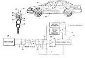
- FIG. 1is a diagrammatic view of a vehicle security system in which a charging system of the present invention operates.
- FIG. 2is a schematic circuit diagram of the charging system of the present invention.
- FIG. 1diagrammatically illustrates a vehicle security system, generally indicated at 20 .
- a transmittergenerally indicated at 22 , is shown as a key fob having a plastic housing 24 that is conveniently sized to be carried in a purse or pocket, for example.
- a plurality of pushbutton switches 26 , 27 , 28 and 30are selectively activated by a user to achieve a desired operation in the vehicle security system.
- the key fobconveniently serves as a key ring for holding one or more keys 32 in a conventional manner.
- a receiver or base station 34responds to the signals sent from the transmitter 22 .
- the base station 34is supported on a vehicle 36 and controls various security system functions in a conventional manner.
- the charging system of the present inventionincludes a charging circuit that is activated by an RF signal transmitted by the transmitter 22 in response to a low voltage threshold detected by a voltage monitoring circuit, but is deactivated when the battery is fully charged such as once a specified period of charging time has transpired instead of monitoring a low voltage threshold.
- the systemcan also allow for continuous charging until the battery reaches an upper level threshold as also monitored by the voltage monitoring circuit. The process is performed automatically without any user intervention.
- the charging methodcan be performed using inductive coupling or direct contact. Below is an example of how an inductively-coupled charging system of the invention would function.
- the base station 34includes a conventional charging circuit including a series or parallel connected capacitor 31 and inductor or coil 33 .
- the charging circuitgenerates a magnetic field preferably having a frequency of about 125 KHz.
- the charging circuitfurther includes a parallel or series connected coil 35 and an inductor or coil 37 to complete the transfer of electrical energy from the coil 33 .
- a voltage regulator 39 of the charging circuitregulates the charging voltage applied to a battery 42 .
- a pair of clamping zenar diodes 41 and 43clamp the inputs to an amplifier 45 of the transmitter 22 .
- the amplified outputis applied to the LF transceiver portion of a CPU/LF transceiver 40 .
- the battery-operated remote keyless entry (RKE) transmitter 22is equipped with a voltage level detector 38 connected to the CPU or microprocessor portion of the CPU/LF (low frequency) transceiver 40 that monitors the voltage of the battery 42 .
- the RKE transmitter 22is also typically equipped with an immobilizer feature that allows for battery-less, inductive operation when placed in the inductive or magnetic field generated by the base station immobilizer located in the vehicle 36 .
- the detector 38provides a signal to the microprocessor of the CPU/LF transceiver 40 which changes a bit in the pulses transmitted by the transmitter 22 to let the base station 34 , that works in conjunction with the RKE transmitter 22 , know that the battery voltage is low.
- the charging circuit of the base station 34 located in the vehicle 36continues to activate the inductive field until the RKE transmitter battery 42 is fully charged.
- the methodology for determining when the battery is “fully charged”utilizes either one or both of the following:
- the detector 38 and the CPU/LF transceiver 40 of the transmitter 22monitor voltage until an upper voltage threshold is achieved, then the transmitter 22 transmits a pulse to the base station 34 indicating such.
- the base station 34once it receives a low voltage indication, continues to charge that particular transmitter 22 for a specified period of time before the charging field generated by the charging circuit is shut down.
- a charging time monitoring circuit including a second microprocessor of the base station 34tracks the charging time together with an associated transmitter ID, as multiple transmitters may be used with a single base station 34 .
- This processis performed to eliminate unnecessary charging cycles and to fully charge the battery 42 between cycles instead of only charging the battery 42 to a level slightly above the low voltage threshold.
Landscapes
- Engineering & Computer Science (AREA)
- Power Engineering (AREA)
- Computer Networks & Wireless Communication (AREA)
- Charge And Discharge Circuits For Batteries Or The Like (AREA)
- Secondary Cells (AREA)
Abstract
Description
Claims (8)
Priority Applications (1)
| Application Number | Priority Date | Filing Date | Title |
|---|---|---|---|
| US09/924,284US6366051B1 (en) | 2000-05-08 | 2001-08-08 | System for automatically charging the battery of a remote transmitter for use in a vehicle security system |
Applications Claiming Priority (2)
| Application Number | Priority Date | Filing Date | Title |
|---|---|---|---|
| US09/566,585US6291968B1 (en) | 2000-05-08 | 2000-05-08 | System for automatically charging the battery of a remote transmitter for use in a vehicle security system |
| US09/924,284US6366051B1 (en) | 2000-05-08 | 2001-08-08 | System for automatically charging the battery of a remote transmitter for use in a vehicle security system |
Related Parent Applications (1)
| Application Number | Title | Priority Date | Filing Date |
|---|---|---|---|
| US09/566,585ContinuationUS6291968B1 (en) | 2000-05-08 | 2000-05-08 | System for automatically charging the battery of a remote transmitter for use in a vehicle security system |
Publications (2)
| Publication Number | Publication Date |
|---|---|
| US20020027424A1 US20020027424A1 (en) | 2002-03-07 |
| US6366051B1true US6366051B1 (en) | 2002-04-02 |
Family
ID=24263504
Family Applications (2)
| Application Number | Title | Priority Date | Filing Date |
|---|---|---|---|
| US09/566,585Expired - Fee RelatedUS6291968B1 (en) | 2000-05-08 | 2000-05-08 | System for automatically charging the battery of a remote transmitter for use in a vehicle security system |
| US09/924,284Expired - LifetimeUS6366051B1 (en) | 2000-05-08 | 2001-08-08 | System for automatically charging the battery of a remote transmitter for use in a vehicle security system |
Family Applications Before (1)
| Application Number | Title | Priority Date | Filing Date |
|---|---|---|---|
| US09/566,585Expired - Fee RelatedUS6291968B1 (en) | 2000-05-08 | 2000-05-08 | System for automatically charging the battery of a remote transmitter for use in a vehicle security system |
Country Status (2)
| Country | Link |
|---|---|
| US (2) | US6291968B1 (en) |
| DE (1) | DE10121772A1 (en) |
Cited By (18)
| Publication number | Priority date | Publication date | Assignee | Title |
|---|---|---|---|---|
| US20060197650A1 (en)* | 2005-03-02 | 2006-09-07 | Magnadyne Corporation | Passive transmitter |
| US20080024267A1 (en)* | 2005-03-02 | 2008-01-31 | Magnadyne Corporation | Forced arming |
| US20080229224A1 (en)* | 2007-03-16 | 2008-09-18 | Sony Computer Entertainment Inc. | User interface in which object is assigned to data file and application |
| US20110115605A1 (en)* | 2009-11-17 | 2011-05-19 | Strattec Security Corporation | Energy harvesting system |
| US20110153338A1 (en)* | 2009-12-17 | 2011-06-23 | Noel Wayne Anderson | System and method for deploying portable landmarks |
| US20110153072A1 (en)* | 2009-12-17 | 2011-06-23 | Noel Wayne Anderson | Enhanced visual landmark for localization |
| WO2013112614A1 (en)* | 2012-01-23 | 2013-08-01 | Utah State University | Wireless power transfer system |
| US9140763B2 (en) | 2011-09-19 | 2015-09-22 | Utah State University | Wireless power transfer test system |
| US9240270B2 (en) | 2011-10-07 | 2016-01-19 | Utah State University | Wireless power transfer magnetic couplers |
| US9246409B2 (en) | 2011-03-11 | 2016-01-26 | Utah State University | Method and apparatus for controlling LCL converters using asymmetric voltage cancellation techniques |
| US9425630B2 (en) | 2011-09-08 | 2016-08-23 | Hewlett-Packard Development Company, L.P. | Extending battery life for a rechargeable battery |
| US20180262037A1 (en)* | 2017-03-09 | 2018-09-13 | Werner Meskens | Multi-loop implant charger |
| US10270493B2 (en) | 2017-07-14 | 2019-04-23 | The Chamberlain Group, Inc. | Portable rechargeable transmitter |
| US10997810B2 (en) | 2019-05-16 | 2021-05-04 | The Chamberlain Group, Inc. | In-vehicle transmitter training |
| US11074773B1 (en) | 2018-06-27 | 2021-07-27 | The Chamberlain Group, Inc. | Network-based control of movable barrier operators for autonomous vehicles |
| US11220856B2 (en) | 2019-04-03 | 2022-01-11 | The Chamberlain Group Llc | Movable barrier operator enhancement device and method |
| US11423717B2 (en) | 2018-08-01 | 2022-08-23 | The Chamberlain Group Llc | Movable barrier operator and transmitter pairing over a network |
| US11778464B2 (en) | 2017-12-21 | 2023-10-03 | The Chamberlain Group Llc | Security system for a moveable barrier operator |
Families Citing this family (18)
| Publication number | Priority date | Publication date | Assignee | Title |
|---|---|---|---|---|
| US6785748B2 (en)* | 2000-07-18 | 2004-08-31 | Canon Kabushiki Kaisha | Image communication apparatus wirelessly connectable to other apparatuses, system having the image communication apparatus, and method for controlling the same |
| US6943666B2 (en)* | 2001-02-15 | 2005-09-13 | Agere Systems, Inc. | Recharging key based wireless device |
| KR20030047198A (en)* | 2001-12-08 | 2003-06-18 | 현대자동차주식회사 | Charging system for transmitter of vehicle |
| US6838985B2 (en)* | 2002-03-25 | 2005-01-04 | Lear Corporation | System and method for remote tire pressure monitoring with low frequency initiation |
| US20060061483A1 (en)* | 2004-09-17 | 2006-03-23 | Smith Timothy D | Monitoring and security system and method |
| DE102005024227A1 (en)* | 2005-05-25 | 2006-11-30 | Audia Akustik Gmbh | Method and device for inductive charging of hearing aids |
| US20070055472A1 (en)* | 2005-08-23 | 2007-03-08 | Cisco Technology, Inc. | Method and system for transfer of data in a wireless network |
| DE102007035904B4 (en)* | 2007-07-31 | 2009-09-17 | Continental Automotive Gmbh | User identification device |
| EP2071497A1 (en)* | 2007-12-10 | 2009-06-17 | Gemalto SA | Contactless battery charger method and device |
| US8855554B2 (en) | 2008-03-05 | 2014-10-07 | Qualcomm Incorporated | Packaging and details of a wireless power device |
| KR20130010089A (en) | 2008-04-21 | 2013-01-25 | 퀄컴 인코포레이티드 | Short range efficient wireless power transfer |
| US8497658B2 (en) | 2009-01-22 | 2013-07-30 | Qualcomm Incorporated | Adaptive power control for wireless charging of devices |
| US9537324B2 (en) | 2011-12-14 | 2017-01-03 | Fleetwood Group, Inc. | Audience response system with batteryless response units |
| FR2994339B1 (en)* | 2012-08-06 | 2014-09-12 | Commissariat Energie Atomique | METHOD FOR MANAGING AND DIAGNOSING A BATTERY |
| US9058704B2 (en)* | 2012-09-04 | 2015-06-16 | Craig Alexander Colburn | Electronic vehicle key |
| US10424956B2 (en)* | 2017-06-19 | 2019-09-24 | Lear Corporation | Methods and systems for handling passive entry passive start (PEPS) remote controller battery self-discharge |
| US10793108B2 (en)* | 2018-11-09 | 2020-10-06 | Ford Global Technologies, Llc | Bluetooth-enabled key fob |
| CN117152868A (en)* | 2023-08-29 | 2023-12-01 | 英业达科技有限公司 | Smart key device |
Citations (13)
| Publication number | Priority date | Publication date | Assignee | Title |
|---|---|---|---|---|
| US4395672A (en) | 1981-04-02 | 1983-07-26 | Gassaway Lee V | Battery charger controller |
| US5572110A (en) | 1994-12-15 | 1996-11-05 | Intel Corporation | Smart battery charger system |
| US5606240A (en) | 1992-07-21 | 1997-02-25 | Sanyo Electric Co., Ltd. | Battery charger |
| US5640079A (en) | 1994-08-29 | 1997-06-17 | Andrew Corporation | Battery charger for portable rechargeable batteries |
| US5717387A (en) | 1990-01-19 | 1998-02-10 | Prince Corporation | Remote vehicle programming system |
| US5726555A (en) | 1995-02-28 | 1998-03-10 | Nec Corporation | Battery charger capable of displaying necessary charging time |
| US5754029A (en) | 1993-11-23 | 1998-05-19 | Thomson Consumer Electronics, Inc. | Battery charger with calendar control |
| US5847546A (en) | 1992-11-13 | 1998-12-08 | Packard Bell Nec | System and apparatus for generating a continuosly variable reference signal for controlling battery cell charging |
| US5850188A (en) | 1996-12-10 | 1998-12-15 | United Technologies Automotive, Inc. | Self-diagnosing remote entry apparatus |
| US5870685A (en) | 1996-09-04 | 1999-02-09 | Ericsson Inc. | Mobile station operations management based on battery capacity |
| US6011546A (en) | 1995-11-01 | 2000-01-04 | International Business Machines Corporation | Programming structure for user interfaces |
| US6016047A (en) | 1996-11-21 | 2000-01-18 | U.S. Philips Corporation | Battery management system and battery simulator |
| US6023151A (en) | 1998-03-16 | 2000-02-08 | Eveready Battery Company, Inc. | Method and device for enhancing smart battery performance |
- 2000
- 2000-05-08USUS09/566,585patent/US6291968B1/ennot_activeExpired - Fee Related
- 2001
- 2001-05-04DEDE10121772Apatent/DE10121772A1/ennot_activeCeased
- 2001-08-08USUS09/924,284patent/US6366051B1/ennot_activeExpired - Lifetime
Patent Citations (13)
| Publication number | Priority date | Publication date | Assignee | Title |
|---|---|---|---|---|
| US4395672A (en) | 1981-04-02 | 1983-07-26 | Gassaway Lee V | Battery charger controller |
| US5717387A (en) | 1990-01-19 | 1998-02-10 | Prince Corporation | Remote vehicle programming system |
| US5606240A (en) | 1992-07-21 | 1997-02-25 | Sanyo Electric Co., Ltd. | Battery charger |
| US5847546A (en) | 1992-11-13 | 1998-12-08 | Packard Bell Nec | System and apparatus for generating a continuosly variable reference signal for controlling battery cell charging |
| US5754029A (en) | 1993-11-23 | 1998-05-19 | Thomson Consumer Electronics, Inc. | Battery charger with calendar control |
| US5640079A (en) | 1994-08-29 | 1997-06-17 | Andrew Corporation | Battery charger for portable rechargeable batteries |
| US5572110A (en) | 1994-12-15 | 1996-11-05 | Intel Corporation | Smart battery charger system |
| US5726555A (en) | 1995-02-28 | 1998-03-10 | Nec Corporation | Battery charger capable of displaying necessary charging time |
| US6011546A (en) | 1995-11-01 | 2000-01-04 | International Business Machines Corporation | Programming structure for user interfaces |
| US5870685A (en) | 1996-09-04 | 1999-02-09 | Ericsson Inc. | Mobile station operations management based on battery capacity |
| US6016047A (en) | 1996-11-21 | 2000-01-18 | U.S. Philips Corporation | Battery management system and battery simulator |
| US5850188A (en) | 1996-12-10 | 1998-12-15 | United Technologies Automotive, Inc. | Self-diagnosing remote entry apparatus |
| US6023151A (en) | 1998-03-16 | 2000-02-08 | Eveready Battery Company, Inc. | Method and device for enhancing smart battery performance |
Cited By (28)
| Publication number | Priority date | Publication date | Assignee | Title |
|---|---|---|---|---|
| US20060197650A1 (en)* | 2005-03-02 | 2006-09-07 | Magnadyne Corporation | Passive transmitter |
| US20080024267A1 (en)* | 2005-03-02 | 2008-01-31 | Magnadyne Corporation | Forced arming |
| US20080229224A1 (en)* | 2007-03-16 | 2008-09-18 | Sony Computer Entertainment Inc. | User interface in which object is assigned to data file and application |
| US20110115605A1 (en)* | 2009-11-17 | 2011-05-19 | Strattec Security Corporation | Energy harvesting system |
| US20110153338A1 (en)* | 2009-12-17 | 2011-06-23 | Noel Wayne Anderson | System and method for deploying portable landmarks |
| US20110153072A1 (en)* | 2009-12-17 | 2011-06-23 | Noel Wayne Anderson | Enhanced visual landmark for localization |
| US9246409B2 (en) | 2011-03-11 | 2016-01-26 | Utah State University | Method and apparatus for controlling LCL converters using asymmetric voltage cancellation techniques |
| US9425630B2 (en) | 2011-09-08 | 2016-08-23 | Hewlett-Packard Development Company, L.P. | Extending battery life for a rechargeable battery |
| US9140763B2 (en) | 2011-09-19 | 2015-09-22 | Utah State University | Wireless power transfer test system |
| US9240270B2 (en) | 2011-10-07 | 2016-01-19 | Utah State University | Wireless power transfer magnetic couplers |
| US9123467B2 (en) | 2012-01-23 | 2015-09-01 | Utah State University | Switch wear leveling |
| US9269489B2 (en) | 2012-01-23 | 2016-02-23 | Utah State University | Wireless power transfer system |
| WO2013112614A1 (en)* | 2012-01-23 | 2013-08-01 | Utah State University | Wireless power transfer system |
| US9761370B2 (en) | 2012-01-23 | 2017-09-12 | United States Department Of Energy | Dual side control for inductive power transfer |
| US20180262037A1 (en)* | 2017-03-09 | 2018-09-13 | Werner Meskens | Multi-loop implant charger |
| US10530177B2 (en)* | 2017-03-09 | 2020-01-07 | Cochlear Limited | Multi-loop implant charger |
| US10270493B2 (en) | 2017-07-14 | 2019-04-23 | The Chamberlain Group, Inc. | Portable rechargeable transmitter |
| US12108248B2 (en) | 2017-12-21 | 2024-10-01 | The Chamberlain Group Llc | Security system for a moveable barrier operator |
| US11778464B2 (en) | 2017-12-21 | 2023-10-03 | The Chamberlain Group Llc | Security system for a moveable barrier operator |
| US11763616B1 (en) | 2018-06-27 | 2023-09-19 | The Chamberlain Group Llc | Network-based control of movable barrier operators for autonomous vehicles |
| US11074773B1 (en) | 2018-06-27 | 2021-07-27 | The Chamberlain Group, Inc. | Network-based control of movable barrier operators for autonomous vehicles |
| US12056971B1 (en) | 2018-06-27 | 2024-08-06 | The Chamberlain Group Llc. | Network-based control of movable barrier operators for autonomous vehicles |
| US11869289B2 (en) | 2018-08-01 | 2024-01-09 | The Chamberlain Group Llc | Movable barrier operator and transmitter pairing over a network |
| US11423717B2 (en) | 2018-08-01 | 2022-08-23 | The Chamberlain Group Llc | Movable barrier operator and transmitter pairing over a network |
| US12354422B2 (en) | 2018-08-01 | 2025-07-08 | The Chamberlain Group Llc | Movable barrier operator and transmitter pairing over a network |
| US11220856B2 (en) | 2019-04-03 | 2022-01-11 | The Chamberlain Group Llc | Movable barrier operator enhancement device and method |
| US11462067B2 (en) | 2019-05-16 | 2022-10-04 | The Chamberlain Group Llc | In-vehicle transmitter training |
| US10997810B2 (en) | 2019-05-16 | 2021-05-04 | The Chamberlain Group, Inc. | In-vehicle transmitter training |
Also Published As
| Publication number | Publication date |
|---|---|
| DE10121772A1 (en) | 2001-11-15 |
| US6291968B1 (en) | 2001-09-18 |
| US20020027424A1 (en) | 2002-03-07 |
Similar Documents
| Publication | Publication Date | Title |
|---|---|---|
| US6366051B1 (en) | System for automatically charging the battery of a remote transmitter for use in a vehicle security system | |
| JP7297087B2 (en) | Method for starting electric scooter using replaceable battery pack of wireless communication system | |
| US8129942B2 (en) | Contactless charging method for charging battery | |
| EP2086085B1 (en) | Non-contact charger and non-contact charge system | |
| CN103107585B (en) | For carrying out the system and method for induction charging to battery | |
| US20110115605A1 (en) | Energy harvesting system | |
| US20060028176A1 (en) | Cellular telephone battery recharging apparatus | |
| US20060145659A1 (en) | Battery pack system and method for waking up a charge control circuit of a mobile communication device | |
| US5859873A (en) | Method and arrangement for non-contact transmission of measured values | |
| US10424957B2 (en) | Methods and systems for handling passive entry passive start (PEPS) remote controller battery self-discharge | |
| CN105226745B (en) | Electric car wireless charging battery group and its charging method and electric car | |
| JP2004328916A (en) | Charging apparatus | |
| EP0684680B1 (en) | Identification apparatus and method | |
| US7876206B2 (en) | Procedure and facility for transmission between a control device and a wheel module | |
| US20200274390A1 (en) | A wireless power transceiver device and an associates method thereof | |
| GB2358427A (en) | Automatic locking | |
| EP3889917B1 (en) | System and method of optimized backup functionality for electronic control key | |
| CN108334920B (en) | Composite intelligent card for vehicle charging and power supply management method thereof | |
| WO1995006994A1 (en) | Tracking external power supply | |
| JPH10503565A (en) | Key with rechargeable energy storage | |
| JP3282194B2 (en) | Charging device | |
| CN109245327B (en) | Intelligent lock and use method thereof | |
| KR100769962B1 (en) | Anti-lost radio transceiver mounted on shoes | |
| CN214412343U (en) | Intelligent charging system and charging equipment | |
| CN113205626B (en) | Intelligent control system and control method for electric bicycle battery |
Legal Events
| Date | Code | Title | Description |
|---|---|---|---|
| STCF | Information on status: patent grant | Free format text:PATENTED CASE | |
| FPAY | Fee payment | Year of fee payment:4 | |
| AS | Assignment | Owner name:JPMORGAN CHASE BANK, N.A., AS GENERAL ADMINISTRATI Free format text:SECURITY AGREEMENT;ASSIGNOR:LEAR CORPORATION;REEL/FRAME:017858/0719 Effective date:20060425 | |
| FPAY | Fee payment | Year of fee payment:8 | |
| AS | Assignment | Owner name:JPMORGAN CHASE BANK, N.A., AS ADMINISTRATIVE AGENT Free format text:GRANT OF FIRST LIEN SECURITY INTEREST IN PATENT RIGHTS;ASSIGNOR:LEAR CORPORATION;REEL/FRAME:023519/0267 Effective date:20091109 Owner name:JPMORGAN CHASE BANK, N.A., AS ADMINISTRATIVE AGENT Free format text:GRANT OF SECOND LIEN SECURITY INTEREST IN PATENT RIGHTS;ASSIGNOR:LEAR CORPORATION;REEL/FRAME:023519/0626 Effective date:20091109 | |
| AS | Assignment | Owner name:JPMORGAN CAHSE BANK, N.A., AS AGENT, ILLINOIS Free format text:SECURITY INTEREST;ASSIGNOR:LEAR CORPORATION;REEL/FRAME:030076/0016 Effective date:20130130 Owner name:JPMORGAN CHASE BANK, N.A., AS AGENT, ILLINOIS Free format text:SECURITY INTEREST;ASSIGNOR:LEAR CORPORATION;REEL/FRAME:030076/0016 Effective date:20130130 | |
| REMI | Maintenance fee reminder mailed | ||
| FPAY | Fee payment | Year of fee payment:12 | |
| SULP | Surcharge for late payment | Year of fee payment:11 | |
| AS | Assignment | Owner name:LEAR CORPORATION, MICHIGAN Free format text:RELEASE BY SECURED PARTY;ASSIGNOR:JPMORGAN CHASE BANK, N.A.;REEL/FRAME:032722/0553 Effective date:20100830 | |
| AS | Assignment | Owner name:LEAR CORPORATION, MICHIGAN Free format text:RELEASE BY SECURED PARTY;ASSIGNOR:JPMORGAN CHASE BANK, N.A.;REEL/FRAME:032770/0843 Effective date:20100830 | |
| AS | Assignment | Owner name:LEAR CORPORATION, MICHIGAN Free format text:RELEASE BY SECURED PARTY;ASSIGNOR:JPMORGAN CHASE BANK, N.A., AS AGENT;REEL/FRAME:037701/0340 Effective date:20160104 Owner name:LEAR CORPORATION, MICHIGAN Free format text:RELEASE BY SECURED PARTY;ASSIGNOR:JPMORGAN CHASE BANK, N.A., AS AGENT;REEL/FRAME:037701/0180 Effective date:20160104 Owner name:LEAR CORPORATION, MICHIGAN Free format text:RELEASE BY SECURED PARTY;ASSIGNOR:JPMORGAN CHASE BANK, N.A., AS AGENT;REEL/FRAME:037701/0251 Effective date:20160104 | |
| AS | Assignment | Owner name:LEAR CORPORATION, MICHIGAN Free format text:RELEASE BY SECURED PARTY;ASSIGNOR:JPMORGAN CHASE BANK, N.A., AS AGENT;REEL/FRAME:037702/0911 Effective date:20160104 Owner name:LEAR CORPORATION, MICHIGAN Free format text:RELEASE BY SECURED PARTY;ASSIGNOR:JPMORGAN CHASE BANK, N.A., AS AGENT;REEL/FRAME:037731/0918 Effective date:20160104 |