US6366021B1 - Standing wave particle beam accelerator with switchable beam energy - Google Patents
Standing wave particle beam accelerator with switchable beam energyDownload PDFInfo
- Publication number
- US6366021B1 US6366021B1US09/479,466US47946600AUS6366021B1US 6366021 B1US6366021 B1US 6366021B1US 47946600 AUS47946600 AUS 47946600AUS 6366021 B1US6366021 B1US 6366021B1
- Authority
- US
- United States
- Prior art keywords
- cavity
- probes
- cavities
- accelerator
- coupling
- Prior art date
- Legal status (The legal status is an assumption and is not a legal conclusion. Google has not performed a legal analysis and makes no representation as to the accuracy of the status listed.)
- Expired - Fee Related
Links
- 239000002245particleSubstances0.000titleclaimsabstractdescription17
- 230000008878couplingEffects0.000claimsabstractdescription37
- 238000010168coupling processMethods0.000claimsabstractdescription37
- 238000005859coupling reactionMethods0.000claimsabstractdescription37
- 239000000523sampleSubstances0.000claimsabstractdescription34
- 210000000554irisAnatomy0.000claimsdescription22
- 230000005672electromagnetic fieldEffects0.000claimsdescription9
- 238000003780insertionMethods0.000claimsdescription8
- 230000037431insertionEffects0.000claimsdescription8
- 230000008859changeEffects0.000claimsdescription7
- 239000004020conductorSubstances0.000claims4
- 238000011144upstream manufacturingMethods0.000abstractdescription7
- 230000005684electric fieldEffects0.000abstract2
- 210000001331noseAnatomy0.000description6
- 230000007246mechanismEffects0.000description3
- 230000001133accelerationEffects0.000description2
- 238000010894electron beam technologyMethods0.000description2
- 230000001939inductive effectEffects0.000description2
- 238000000034methodMethods0.000description2
- 238000011282treatmentMethods0.000description2
- 206010028980NeoplasmDiseases0.000description1
- 230000015572biosynthetic processEffects0.000description1
- 230000003247decreasing effectEffects0.000description1
- 235000012489doughnutsNutrition0.000description1
- 230000005284excitationEffects0.000description1
- 238000002347injectionMethods0.000description1
- 239000007924injectionSubstances0.000description1
- 230000003993interactionEffects0.000description1
- 239000002184metalSubstances0.000description1
- 230000035515penetrationEffects0.000description1
- 230000010363phase shiftEffects0.000description1
- 238000000926separation methodMethods0.000description1
- 238000001228spectrumMethods0.000description1
Images


Classifications
- H—ELECTRICITY
- H05—ELECTRIC TECHNIQUES NOT OTHERWISE PROVIDED FOR
- H05H—PLASMA TECHNIQUE; PRODUCTION OF ACCELERATED ELECTRICALLY-CHARGED PARTICLES OR OF NEUTRONS; PRODUCTION OR ACCELERATION OF NEUTRAL MOLECULAR OR ATOMIC BEAMS
- H05H7/00—Details of devices of the types covered by groups H05H9/00, H05H11/00, H05H13/00
- H05H7/14—Vacuum chambers
- H05H7/18—Cavities; Resonators
- H—ELECTRICITY
- H05—ELECTRIC TECHNIQUES NOT OTHERWISE PROVIDED FOR
- H05H—PLASMA TECHNIQUE; PRODUCTION OF ACCELERATED ELECTRICALLY-CHARGED PARTICLES OR OF NEUTRONS; PRODUCTION OR ACCELERATION OF NEUTRAL MOLECULAR OR ATOMIC BEAMS
- H05H9/00—Linear accelerators
- H05H9/04—Standing-wave linear accelerators
- H—ELECTRICITY
- H01—ELECTRIC ELEMENTS
- H01J—ELECTRIC DISCHARGE TUBES OR DISCHARGE LAMPS
- H01J2223/00—Details of transit-time tubes of the types covered by group H01J2225/00
- H01J2223/16—Circuit elements, having distributed capacitance and inductance, structurally associated with the tube and interacting with the discharge
- H01J2223/18—Resonators
- H01J2223/20—Cavity resonators; Adjustment or tuning thereof
Definitions
- This inventionrelates generally to standing wave particle beam accelerators, and more particularly to charged particle beam accelerators wherein the standing wave in at least one side coupling cavity can be switched to at least two different asymmetries with respect to the coupling of electromagnetic fields to the two adjacent main cavities, to switch the energy of the particle beam.
- Standing wave particle beam acceleratorshave found wide usage in medical accelerators where the high energy particle beam is employed to generate x-rays.
- the output x-ray energymust be stable. It is also desirable that the energy of the particle beam be switchable readily and quickly to provide x-ray beams of different energies to enable different x-ray penetration during medical treatments.
- One technique for controlling the beam energyis to vary the rf energy applied to the accelerating cavities.
- Other implementationshave been described in various patents.
- U.S. Pat. No. 4,286,192 to Tanabe and Vaguinethe energy is controlled by reversing the accelerating fields in one part of the accelerator to decelerate the beam.
- U.S. Pat. No. 4,382,208 to Meddaugh et al.the electromagnetic field distribution is changed in the coupling cavity to control the fields applied to the adjacent resonator cavities.
- U.S. Pat. No. 4,746,839 to Kazusa and Yonedadiscloses the use of two coupling cavities which are switched to control the acceleration fields.
- the particle acceleratorincludes an input cavity for receiving the charged particles, intermediate accelerating cavities and an output cavity, and a plurality of coupling cavities connecting adjacent pairs of said cavities along the accelerator, at least one of said coupling cavities including means for switching the magnitude of the electromagnetic field coupling to adjacent cavities between a first level and at least two additional levels to provide output energy at least three levels.
- FIG. 1is a schematic cross-sectional view of a side cavity coupled standing wave particle beam accelerator.
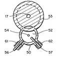
- FIG. 2is a sectional view taken along the line 2 — 2 of FIG. 1, showing the side cavity in accordance with one embodiment of the invention.
- FIG. 3is an enlarged plan view taken generally along the line 3 — 3 of FIG. 2 .
- FIG. 4is a plan view of another embodiment of the present invention.
- FIG. 1is a schematic axial sectional view of a charged particle standing wave accelerator structure embodying the invention. It comprises a chain of electromagnetically coupled resonant cavities. A linear beam of electrons 12 is injected into the accelerator by a conventional electron gun source 14 . Beam 12 may be either continuous or pulsed.
- the standing wave accelerator structure 10is excited by microwave power at a frequency near its resonant frequency, between 1000 and 10,000 MHz, in one example 2856 MHz.
- the powerenters one cavity 16 , preferably one of the cavities along the chain, through an iris 15 .
- the accelerating cavities of the chainare of two types, 16 , 18 .
- the cavitiesare doughnut shaped with aligned central beam apertures 17 which permit passage of beam 12 .
- Cavities 16 and 18preferably have projecting noses 19 of optimized configuration in order to improve efficiency of interaction of the microwave power and electron beam.
- the cavities 16 , 18are electromagnetically coupled together through a “side” or “coupling” cavity 20 which is coupled to each of the adjacent pair of cavities by an iris 22 .
- Coupling cavities 20are resonant at the same frequency as accelerating cavities 16 , 18 and do not interact with beam 12 . In this embodiment, they are of cylindrical shape with a pair of axially projecting conductive capacitively coupled noses 24 .
- the frequency of excitationis such that the chain is excited in standing wave resonance with a ⁇ /2 radian phase shift between each coupling cavity and the adjacent accelerating cavity.
- ⁇ /2 modehas several advantages. It has the greatest separation of resonant frequency from adjacent modes which might be accidentally excited.
- there are very small electromagnetic fields in coupling cavities 20so the power losses in these non-interacting cavities are small.
- the first and last accelerating cavities 26 and 28are shown as consisting of one-half of an interior cavity 16 , 18 and as a result the overall accelerator structure is symmetric relative to rf input coupler or iris 15 . It is of course understood that the terminal cavities may be fall cavities, the same as cavities 16 , 18 .
- the spacing between accelerating cavities 16 , 18is about one-half of a free-space wavelength, so that electrons accelerated in one cavity 16 will arrive at the next accelerating cavity in right phase relative to the microwave field for additional acceleration.
- beam 12strikes an x-ray target 32 .
- 32may be a vacuum window of metal thin enough to transmit the electrons for particle irradiation of a subject.
- At least one coupling cavityis configured to permit control or adjustment of the output energy of the electron beam.
- the output energyis controlled by making the coupling cavity asymmetrical by a mechanical adjustment.
- the geometrical asymmetryproduces an asymmetry of the electromagnetic field distribution in the coupling cavity 34 so that the magnetic field component is greater at one iris 38 than at the other iris 40 .
- the coupled magnetic fieldis thus greater in the preceding cavities 16 coupled through iris 38 than in the following cavities 18 coupled through iris 40 .
- the ratio of accelerating fields in the cavities 16 and 18is directly proportional to the ratio of magnetic fields on irises 38 and 40 .
- the rf voltage in the accelerating field in the following chain 18can be changed while leaving the accelerating field constant in the cavities 16 near the beam injection region.
- the energy of the output beamcan be selectively adjusted.
- the bunchingcan be optimized there and not degraded by the varying the accelerating field in the output cavities 18 .
- the spread of energies in the output beamis thus made independent of the varying mean output electron energy.
- the varying energy lost to the beam by the output cavities 18will of course change the load impedance seen by the microwave source (not shown) producing small reflected microwave power from iris 15 . This change is small and can easily be compensated either by variable impedance or by adjusting the microwave input power.
- the levels of output energyare generally limited to two levels, a first energy level with the side cavity configured not to disturb the configuration of the fields within the cavity whereby there is equal inductive coupling to the adjacent cavities through the irises 38 , 40 and a second energy level wherein the fields within the cavity are changed by changing the physical configuration of the cavity and the inductive coupling through the irises to change the field within the cavities 16 , 18 to thereby alter the magnetic field at the two irises.
- the side or coupling cavity in accordance with the present inventionis configured with two or more asymmetrically positioned plungers or probes.
- the probesare preferably circular cylinders although they could be square or other shaped cylinders.
- the coupling cavity 34FIG. 2, it includes a cylindrical cup-shaped body 50 which forms a cylindrical coupling cavity 52 attached to the main body 53 of the accelerator. Noses or members 54 having opposed end faces extend axially into the cavity. Movable plungers or, probes 56 , 57 , FIG.
- the mechanismcan comprise electrically actuated solenoids or pneumatically operated cylinders. Movement of the plungers is through the vacuum wall via bellows 61 , 62 which provide a vacuum seal.
- the motion of the plungersis programmed to alter the magnetic fields within the cavity to provide either a symmetric field with both plungers withdrawn, or different asymmetric magnetic fields with one or the other plunger 56 , 57 moved into the cavity a predetermined distance from adjacent a nose 54 to alter the magnetic fields which couple to the irises.
- the asymmetry which is introducedcan be controlled by the diameter of the plungers and, secondly and more importantly, by the position of the end of the plunger inside the cavity with respect to the nose 54 .
- probes upstream of the longitudinal center line of the cavitydecrease the magnetic coupling to the downstream iris, and therefore decrease the energy output while probes on the downstream side of the longitudinal center of the cavity increase the downstream magnetic, coupling to the downstream iris and therefore increase the energy output.
- the degree of insertion and size of one probecan be selected to decrease the magnetic coupling to the downstream iris a first amount as compared to the upstream iris to decrease the output energy by a predetermined amount.
- the degree of insertion and size of the other probecan be selected to decrease the magnetic coupling by a different amount to decrease the output power by a second amount.
- the output energywas 18 MeV and was shifted to 10 MeV and 6 MeV, respectively, by inserting one or the other of the plungers.
- tuning requirementsthat have not yet been described.
- the normal requirement that the switched side-cavity be tuned to the same frequency as are the other side cavitiescannot be violated. To do so compromises the stability of the guide.
- the tuning requirementis fulfilled primarily by varying the diameter of the probe and the degree of insertion. Generally, the upstream and downstream magnetic fields are such that there is no resulting field in the switch cavity.
- the probes 56 a , 57 aare separated longitudinally along the length of the cavity whereby one probe is disposed upstream of the longitudinal center of the cavity and the other downstream.
- insertion of the upstream probe 56 awill decrease magnetic coupling through the downstream iris and decrease the output energy as compared to both probes being withdrawn.
- Insertion of the downstream probe 57 awill increase the magnetic coupling through the downstream iris, and increase the output energy as compared to both probes being withdrawn.
- the energymay be increased from 10 MeV to 18 MeV or decreased from 10 MeV to 6 MeV.
- an acceleratorin which the beam energy can be switched to three levels using two radially extending probes.
- the probesare radially inserted from two different directions in a “V” configuration. This configuration allows the mechanisms which support and move each of the probes to clear one another.
- the use of two probesprovides for insertion of the probes individually with the diameter of the probes selected to maintain resonance and achieve three levels of output power with minimum energy spread.
Landscapes
- Physics & Mathematics (AREA)
- Engineering & Computer Science (AREA)
- Plasma & Fusion (AREA)
- Spectroscopy & Molecular Physics (AREA)
- Particle Accelerators (AREA)
- Radiation-Therapy Devices (AREA)
Abstract
Description
This invention relates generally to standing wave particle beam accelerators, and more particularly to charged particle beam accelerators wherein the standing wave in at least one side coupling cavity can be switched to at least two different asymmetries with respect to the coupling of electromagnetic fields to the two adjacent main cavities, to switch the energy of the particle beam.
Standing wave particle beam accelerators have found wide usage in medical accelerators where the high energy particle beam is employed to generate x-rays. In this application, the output x-ray energy must be stable. It is also desirable that the energy of the particle beam be switchable readily and quickly to provide x-ray beams of different energies to enable different x-ray penetration during medical treatments.
One technique for controlling the beam energy is to vary the rf energy applied to the accelerating cavities. Other implementations have been described in various patents. In U.S. Pat. No. 4,286,192 to Tanabe and Vaguine the energy is controlled by reversing the accelerating fields in one part of the accelerator to decelerate the beam. In U.S. Pat. No. 4,382,208 to Meddaugh et al., the electromagnetic field distribution is changed in the coupling cavity to control the fields applied to the adjacent resonator cavities. U.S. Pat. No. 4,746,839 to Kazusa and Yoneda discloses the use of two coupling cavities which are switched to control the acceleration fields.
It is an object of the present invention to provide a switchable energy side-coupled standing wave particle beam accelerator.
It is another object of the present invention to provide a switchable energy side-coupled cavity standing wave particle beam accelerator which is switchable to provide three levels of output energy with an insubstantial change in frequency and energy spectrum spread.
To achieve the foregoing and other objects of the invention, the particle accelerator includes an input cavity for receiving the charged particles, intermediate accelerating cavities and an output cavity, and a plurality of coupling cavities connecting adjacent pairs of said cavities along the accelerator, at least one of said coupling cavities including means for switching the magnitude of the electromagnetic field coupling to adjacent cavities between a first level and at least two additional levels to provide output energy at least three levels.
The foregoing and other objects of the invention will be better understood from the following description when read in conjunction with the accompanying drawings in which:
FIG. 1 is a schematic cross-sectional view of a side cavity coupled standing wave particle beam accelerator.
FIG. 2 is a sectional view taken along the line2—2 of FIG. 1, showing the side cavity in accordance with one embodiment of the invention.
FIG. 3 is an enlarged plan view taken generally along the line3—3 of FIG.2.
FIG. 4 is a plan view of another embodiment of the present invention.
FIG. 1 is a schematic axial sectional view of a charged particle standing wave accelerator structure embodying the invention. It comprises a chain of electromagnetically coupled resonant cavities. A linear beam ofelectrons 12 is injected into the accelerator by a conventionalelectron gun source 14.Beam 12 may be either continuous or pulsed.
The standingwave accelerator structure 10 is excited by microwave power at a frequency near its resonant frequency, between 1000 and 10,000 MHz, in one example 2856 MHz. The power enters onecavity 16, preferably one of the cavities along the chain, through aniris 15.
The accelerating cavities of the chain are of two types,16,18. The cavities are doughnut shaped with alignedcentral beam apertures 17 which permit passage ofbeam 12.Cavities noses 19 of optimized configuration in order to improve efficiency of interaction of the microwave power and electron beam. For electron accelerators, thecavities cavity 20 which is coupled to each of the adjacent pair of cavities by aniris 22.Coupling cavities 20 are resonant at the same frequency as acceleratingcavities beam 12. In this embodiment, they are of cylindrical shape with a pair of axially projecting conductive capacitively couplednoses 24.
The frequency of excitation is such that the chain is excited in standing wave resonance with a π/2 radian phase shift between each coupling cavity and the adjacent accelerating cavity. Thus, there is a π radian shift between adjacent acceleratingcavities coupling cavities 20 so the power losses in these non-interacting cavities are small. The first and last acceleratingcavities interior cavity iris 15. It is of course understood that the terminal cavities may be fall cavities, the same ascavities
The spacing between acceleratingcavities cavity 16 will arrive at the next accelerating cavity in right phase relative to the microwave field for additional acceleration. After being accelerated,beam 12 strikes anx-ray target 32. Alternatively,32 may be a vacuum window of metal thin enough to transmit the electrons for particle irradiation of a subject.
If all the acceleratingcavities coupling cavities 20 are similar and mirror-image symmetrical about their center planes, the field in all accelerating cavities will be substantially the same.
In the prior art, as is exemplified in U.S. Pat. Nos. 4,286,192, 4,382,208 and 4,746,839, all of which are incorporated herein in their entirety by reference, at least one coupling cavity is configured to permit control or adjustment of the output energy of the electron beam. In U.S. Pat. No. 4,382,208 the output energy is controlled by making the coupling cavity asymmetrical by a mechanical adjustment. The geometrical asymmetry produces an asymmetry of the electromagnetic field distribution in thecoupling cavity 34 so that the magnetic field component is greater at oneiris 38 than at theother iris 40. The coupled magnetic field is thus greater in the precedingcavities 16 coupled throughiris 38 than in the followingcavities 18 coupled throughiris 40. Since thecavities cavities irises coupling cavity 34, the rf voltage in the accelerating field in the followingchain 18 can be changed while leaving the accelerating field constant in thecavities 16 near the beam injection region. Thus, the energy of the output beam can be selectively adjusted.
Since the formation of electron bunches from an initial continuous beam takes place in thefirst cavities 16 traversed, the bunching can be optimized there and not degraded by the varying the accelerating field in theoutput cavities 18. The spread of energies in the output beam is thus made independent of the varying mean output electron energy.
The varying energy lost to the beam by theoutput cavities 18 will of course change the load impedance seen by the microwave source (not shown) producing small reflected microwave power fromiris 15. This change is small and can easily be compensated either by variable impedance or by adjusting the microwave input power.
In the prior art, the levels of output energy are generally limited to two levels, a first energy level with the side cavity configured not to disturb the configuration of the fields within the cavity whereby there is equal inductive coupling to the adjacent cavities through theirises cavities
There is a need in many medical procedures for three or more levels of output energy to form different levels of x-rays for treatment of tumors, etc., which lie at different depths within the patient. The side or coupling cavity in accordance with the present invention is configured with two or more asymmetrically positioned plungers or probes. The probes are preferably circular cylinders although they could be square or other shaped cylinders. Referring now particularly to thecoupling cavity 34, FIG. 2, it includes a cylindrical cup-shapedbody 50 which forms acylindrical coupling cavity 52 attached to themain body 53 of the accelerator. Noses ormembers 54 having opposed end faces extend axially into the cavity. Movable plungers or, probes56,57, FIG. 2, extend radially into the cavity through thewall 50 of the cylindrical coupling cavity with their axis defining a “V”. This provides physical room for the mechanisms which engage the ends of the probes to advance and retract theprobes other plunger nose 54 to alter the magnetic fields which couple to the irises. The asymmetry which is introduced can be controlled by the diameter of the plungers and, secondly and more importantly, by the position of the end of the plunger inside the cavity with respect to thenose 54. Typically, probes upstream of the longitudinal center line of the cavity decrease the magnetic coupling to the downstream iris, and therefore decrease the energy output while probes on the downstream side of the longitudinal center of the cavity increase the downstream magnetic, coupling to the downstream iris and therefore increase the energy output.
Since the probes in FIGS. 2 and 3 are located adjacent theupstream nose 54, the degree of insertion and size of one probe can be selected to decrease the magnetic coupling to the downstream iris a first amount as compared to the upstream iris to decrease the output energy by a predetermined amount. The degree of insertion and size of the other probe can be selected to decrease the magnetic coupling by a different amount to decrease the output power by a second amount. In one example, with both probes withdrawn, the output energy was 18 MeV and was shifted to 10 MeV and 6 MeV, respectively, by inserting one or the other of the plungers.
In addition, there are tuning requirements that have not yet been described. In particular, the normal requirement that the switched side-cavity be tuned to the same frequency as are the other side cavities cannot be violated. To do so compromises the stability of the guide. The tuning requirement is fulfilled primarily by varying the diameter of the probe and the degree of insertion. Generally, the upstream and downstream magnetic fields are such that there is no resulting field in the switch cavity.
In FIG. 4, theprobes 56a,57aare separated longitudinally along the length of the cavity whereby one probe is disposed upstream of the longitudinal center of the cavity and the other downstream. Thus, insertion of theupstream probe 56awill decrease magnetic coupling through the downstream iris and decrease the output energy as compared to both probes being withdrawn. Insertion of the downstream probe57awill increase the magnetic coupling through the downstream iris, and increase the output energy as compared to both probes being withdrawn. By way of example, the energy may be increased from 10 MeV to 18 MeV or decreased from 10 MeV to 6 MeV.
Thus there has been provided an accelerator in which the beam energy can be switched to three levels using two radially extending probes. The probes are radially inserted from two different directions in a “V” configuration. This configuration allows the mechanisms which support and move each of the probes to clear one another. The use of two probes provides for insertion of the probes individually with the diameter of the probes selected to maintain resonance and achieve three levels of output power with minimum energy spread.
Claims (5)
1. In an accelerator for accelerating a particle beam, a chain of resonant electromagnetic cavities coupled in series along an axis and resonant at approximately the same frequency,
a cylindrical coupling cavity coupled to each of at least two intermediate adjacent cavities through irises,
conductors extending parallel to the axis into said coupling cavity with their ends spaced from one another,
at least first and second probes mounted for independent radial insertion into said coupling cavity at a radial angle with respect to one another, and with their ends adjacent and selectively coupled to one or the other of said conductors to change the distribution of electromagnetic fields in the cavity whereby the electromagnetic field coupling between said two adjacent cavities is changed with the selective insertion of said probes to thereby change the energy of the particle beam from a first value with both probes retracted and uncoupled to a second value with only one probe inserted and coupled to one conductor and a third value with only the other probe inserted and coupled to one the or the other conductor.
2. The accelerator ofclaim 1 in which said first and second probes are both on one side of the longitudinal centerline of the coupling cavity.
3. The accelerator ofclaim 1 in which said first and second probes are on opposite sides of the longitudinal centerline of the coupling cavity.
4. The accelerator of claims1,2 or3 wherein the coupling of the electromagnetic fields to the two adjacent cavities is through irises and the probes change the distribution of electromagnetic field with respect to the irises.
5. The accelerator of claims1,2 or3 an which the diameter of the first and second probes is selected to control the frequency of the cavity.
Priority Applications (6)
| Application Number | Priority Date | Filing Date | Title |
|---|---|---|---|
| US09/479,466US6366021B1 (en) | 2000-01-06 | 2000-01-06 | Standing wave particle beam accelerator with switchable beam energy |
| DE10100130ADE10100130A1 (en) | 2000-01-06 | 2001-01-03 | Standing wave particle beam accelerator with switchable beam energy has at least two probes for independent insertion into coupling volumes to alter electromagnetic field distribution |
| GB0100082AGB2360873B (en) | 2000-01-06 | 2001-01-03 | Standing wave particle beam accelerator with switchable beam energy |
| FR0100090AFR2803715B1 (en) | 2000-01-06 | 2001-01-04 | STATIONARY WAVE PARTICLE BEAM ACCELERATOR |
| SE0100038ASE0100038L (en) | 2000-01-06 | 2001-01-05 | Standing wave particle beam accelerator with interchangeable beam energy |
| JP2001036147AJP2001257099A (en) | 2000-01-06 | 2001-01-09 | Stationary wave particle beam accelerator having changeable beam energy |
Applications Claiming Priority (1)
| Application Number | Priority Date | Filing Date | Title |
|---|---|---|---|
| US09/479,466US6366021B1 (en) | 2000-01-06 | 2000-01-06 | Standing wave particle beam accelerator with switchable beam energy |
Publications (1)
| Publication Number | Publication Date |
|---|---|
| US6366021B1true US6366021B1 (en) | 2002-04-02 |
Family
ID=23904125
Family Applications (1)
| Application Number | Title | Priority Date | Filing Date |
|---|---|---|---|
| US09/479,466Expired - Fee RelatedUS6366021B1 (en) | 2000-01-06 | 2000-01-06 | Standing wave particle beam accelerator with switchable beam energy |
Country Status (6)
| Country | Link |
|---|---|
| US (1) | US6366021B1 (en) |
| JP (1) | JP2001257099A (en) |
| DE (1) | DE10100130A1 (en) |
| FR (1) | FR2803715B1 (en) |
| GB (1) | GB2360873B (en) |
| SE (1) | SE0100038L (en) |
Cited By (64)
| Publication number | Priority date | Publication date | Assignee | Title |
|---|---|---|---|---|
| US6593696B2 (en)* | 2002-01-04 | 2003-07-15 | Siemens Medical Solutions Usa, Inc. | Low dark current linear accelerator |
| US20030146704A1 (en)* | 2002-02-07 | 2003-08-07 | Siemens Medical Solutions Usa, Inc. | Apparatus and method for establishing a Q-factor of a cavity for an accelerator |
| WO2004051311A2 (en) | 2002-12-04 | 2004-06-17 | Varian Medical Systems Technologies, Inc. | Radiation scanning units including a movable platform |
| US20040156477A1 (en)* | 2003-01-31 | 2004-08-12 | Paul Bjorkholm | Radiation scanning of cargo conveyances at seaports and the like |
| US20040195971A1 (en)* | 2003-04-03 | 2004-10-07 | Trail Mark E. | X-ray source employing a compact electron beam accelerator |
| US20040213375A1 (en)* | 2003-04-25 | 2004-10-28 | Paul Bjorkholm | Radiation sources and radiation scanning systems with improved uniformity of radiation intensity |
| US20040247075A1 (en)* | 2003-06-06 | 2004-12-09 | Johnson James H. | Vehicle mounted inspection systems and methods |
| US20050057198A1 (en)* | 2003-08-22 | 2005-03-17 | Hanna Samy M. | Electronic energy switch for particle accelerator |
| WO2005065259A2 (en) | 2003-12-24 | 2005-07-21 | Varian Medical Systems Technologies, Inc. | Standing wave particle beam accelerator |
| US20060011825A1 (en)* | 2002-10-11 | 2006-01-19 | Pirozhenko Vitaly M | Standing-wave electron linear accelerator |
| US20060023835A1 (en)* | 2002-12-04 | 2006-02-02 | Seppi Edward J | Radiation scanning units with reduced detector requirements |
| US20070035260A1 (en)* | 2005-08-09 | 2007-02-15 | Siemens Medical Solutions Usa, Inc. | Dual-plunger energy switch |
| US20070046401A1 (en)* | 2005-08-25 | 2007-03-01 | Meddaugh Gard E | Standing wave particle beam accelerator having a plurality of power inputs |
| US20070096664A1 (en)* | 2004-02-01 | 2007-05-03 | Chongguo Yao | Phase switch and a standing wave linear accelerator with the phase switch |
| US7257188B2 (en) | 2004-03-01 | 2007-08-14 | Varian Medical Systems Technologies, Inc. | Dual energy radiation scanning of contents of an object |
| US20070215813A1 (en)* | 2006-03-17 | 2007-09-20 | Varian Medical Systems Technologies, Inc. | Electronic energy switch |
| US20080014643A1 (en)* | 2006-07-12 | 2008-01-17 | Paul Bjorkholm | Dual angle radiation scanning of objects |
| US20090283682A1 (en)* | 2008-05-19 | 2009-11-19 | Josh Star-Lack | Multi-energy x-ray imaging |
| US20100038563A1 (en)* | 2008-08-12 | 2010-02-18 | Varian Medicals Systems, Inc. | Interlaced multi-energy radiation sources |
| US20100127169A1 (en)* | 2008-11-24 | 2010-05-27 | Varian Medical Systems, Inc. | Compact, interleaved radiation sources |
| US7786823B2 (en) | 2006-06-26 | 2010-08-31 | Varian Medical Systems, Inc. | Power regulators |
| US20110074288A1 (en)* | 2009-09-28 | 2011-03-31 | Varian Medical Systems, Inc. | Energy Switch Assembly for Linear Accelerators |
| US8344340B2 (en) | 2005-11-18 | 2013-01-01 | Mevion Medical Systems, Inc. | Inner gantry |
| US20130063052A1 (en)* | 2010-03-05 | 2013-03-14 | Accuray, Inc. | Interleaving multi-energy x-ray energy operation of a standing wave linear accelerator |
| US8472583B2 (en) | 2010-09-29 | 2013-06-25 | Varian Medical Systems, Inc. | Radiation scanning of objects for contraband |
| US8581523B2 (en) | 2007-11-30 | 2013-11-12 | Mevion Medical Systems, Inc. | Interrupted particle source |
| US20130307437A1 (en)* | 2012-05-17 | 2013-11-21 | Mark Edward Morehouse | Energy Density Intensifier for Accelerating, Compressing and Trapping Charged Particles in a Solenoid Magnetic Field |
| US8791656B1 (en) | 2013-05-31 | 2014-07-29 | Mevion Medical Systems, Inc. | Active return system |
| US8927950B2 (en) | 2012-09-28 | 2015-01-06 | Mevion Medical Systems, Inc. | Focusing a particle beam |
| US8933650B2 (en) | 2007-11-30 | 2015-01-13 | Mevion Medical Systems, Inc. | Matching a resonant frequency of a resonant cavity to a frequency of an input voltage |
| US8952634B2 (en) | 2004-07-21 | 2015-02-10 | Mevion Medical Systems, Inc. | Programmable radio frequency waveform generator for a synchrocyclotron |
| EP2889894A1 (en)* | 2013-12-30 | 2015-07-01 | Nuctech Company Limited | X-ray generating apparatus and x-ray fluoroscopy imaging system equipped with the same |
| US9086496B2 (en) | 2013-11-15 | 2015-07-21 | Varian Medical Systems, Inc. | Feedback modulated radiation scanning systems and methods for reduced radiological footprint |
| CN104822220A (en)* | 2015-04-10 | 2015-08-05 | 中广核中科海维科技发展有限公司 | Standing wave linear accelerating tube with adjustable field strength of beam focusing segment |
| CN104837293A (en)* | 2015-04-10 | 2015-08-12 | 中广核中科海维科技发展有限公司 | Accelerating tube energy adjusting device capable of outputting keV-level and MeV-level ray in transformation manner |
| US9155186B2 (en) | 2012-09-28 | 2015-10-06 | Mevion Medical Systems, Inc. | Focusing a particle beam using magnetic field flutter |
| US9185789B2 (en) | 2012-09-28 | 2015-11-10 | Mevion Medical Systems, Inc. | Magnetic shims to alter magnetic fields |
| US20150366046A1 (en)* | 2014-06-13 | 2015-12-17 | Jefferson Science Associates, Llc | Slot-Coupled CW Standing Wave Accelerating Cavity |
| US9301384B2 (en) | 2012-09-28 | 2016-03-29 | Mevion Medical Systems, Inc. | Adjusting energy of a particle beam |
| CN105722298A (en)* | 2016-03-22 | 2016-06-29 | 上海联影医疗科技有限公司 | Accelerating tube |
| US9545528B2 (en) | 2012-09-28 | 2017-01-17 | Mevion Medical Systems, Inc. | Controlling particle therapy |
| CN106455289A (en)* | 2016-11-14 | 2017-02-22 | 上海联影医疗科技有限公司 | A standing wave accelerating tube and an accelerator with the standing wave accelerating tube |
| US9622335B2 (en) | 2012-09-28 | 2017-04-11 | Mevion Medical Systems, Inc. | Magnetic field regenerator |
| US9661736B2 (en) | 2014-02-20 | 2017-05-23 | Mevion Medical Systems, Inc. | Scanning system for a particle therapy system |
| US9681531B2 (en) | 2012-09-28 | 2017-06-13 | Mevion Medical Systems, Inc. | Control system for a particle accelerator |
| US9723705B2 (en) | 2012-09-28 | 2017-08-01 | Mevion Medical Systems, Inc. | Controlling intensity of a particle beam |
| US9730308B2 (en) | 2013-06-12 | 2017-08-08 | Mevion Medical Systems, Inc. | Particle accelerator that produces charged particles having variable energies |
| CN107333382A (en)* | 2017-08-07 | 2017-11-07 | 沈阳东软医疗系统有限公司 | A side-coupled standing wave accelerating tube and standing wave accelerator |
| US9950194B2 (en) | 2014-09-09 | 2018-04-24 | Mevion Medical Systems, Inc. | Patient positioning system |
| US9962560B2 (en) | 2013-12-20 | 2018-05-08 | Mevion Medical Systems, Inc. | Collimator and energy degrader |
| US10039479B2 (en) | 2013-12-16 | 2018-08-07 | Medtronic Minimed, Inc. | Methods and systems for improving the reliability of orthogonally redundant sensors |
| US20180277276A1 (en)* | 2017-03-27 | 2018-09-27 | Varian Medical Systems, Inc. | Systems and methods for energy modulated radiation therapy |
| US10254739B2 (en) | 2012-09-28 | 2019-04-09 | Mevion Medical Systems, Inc. | Coil positioning system |
| US10258810B2 (en) | 2013-09-27 | 2019-04-16 | Mevion Medical Systems, Inc. | Particle beam scanning |
| US20190272970A1 (en)* | 2018-03-02 | 2019-09-05 | AcceleRAD Technologies, Inc. | Static collimator for reducing spot size of an electron beam |
| US10529536B2 (en) | 2015-10-20 | 2020-01-07 | Technische Universiteit Eindhoven | Electron beam generation for transmission electron microscope |
| US10646728B2 (en) | 2015-11-10 | 2020-05-12 | Mevion Medical Systems, Inc. | Adaptive aperture |
| US10653892B2 (en) | 2017-06-30 | 2020-05-19 | Mevion Medical Systems, Inc. | Configurable collimator controlled using linear motors |
| US10675487B2 (en) | 2013-12-20 | 2020-06-09 | Mevion Medical Systems, Inc. | Energy degrader enabling high-speed energy switching |
| US10925147B2 (en) | 2016-07-08 | 2021-02-16 | Mevion Medical Systems, Inc. | Treatment planning |
| US11103730B2 (en) | 2017-02-23 | 2021-08-31 | Mevion Medical Systems, Inc. | Automated treatment in particle therapy |
| US11191148B2 (en)* | 2018-12-28 | 2021-11-30 | Shanghai United Imaging Healthcare Co., Ltd. | Accelerating apparatus for a radiation device |
| US11291861B2 (en) | 2019-03-08 | 2022-04-05 | Mevion Medical Systems, Inc. | Delivery of radiation by column and generating a treatment plan therefor |
| US12225656B2 (en) | 2018-12-28 | 2025-02-11 | Shanghai United Imaging Healthcare Co., Ltd. | Accelerating apparatus for a radiation device |
Families Citing this family (3)
| Publication number | Priority date | Publication date | Assignee | Title |
|---|---|---|---|---|
| JP4719255B2 (en)* | 2008-07-24 | 2011-07-06 | 三菱電機株式会社 | High frequency accelerator |
| KR20140066347A (en)* | 2012-11-23 | 2014-06-02 | 한국전기연구원 | Linear accelerator combined with pulse electron gun having linear accelerator frequency |
| CN105764230B (en)* | 2016-03-24 | 2019-06-28 | 上海联影医疗科技有限公司 | Accelerating tube, the method and clinac for accelerating charged particle |
Citations (10)
| Publication number | Priority date | Publication date | Assignee | Title |
|---|---|---|---|---|
| US4024426A (en) | 1973-11-30 | 1977-05-17 | Varian Associates, Inc. | Standing-wave linear accelerator |
| US4162423A (en) | 1976-12-14 | 1979-07-24 | C.G.R. Mev | Linear accelerators of charged particles |
| US4286192A (en) | 1979-10-12 | 1981-08-25 | Varian Associates, Inc. | Variable energy standing wave linear accelerator structure |
| US4382208A (en) | 1980-07-28 | 1983-05-03 | Varian Associates, Inc. | Variable field coupled cavity resonator circuit |
| US4400650A (en)* | 1980-07-28 | 1983-08-23 | Varian Associates, Inc. | Accelerator side cavity coupling adjustment |
| US4629938A (en) | 1985-03-29 | 1986-12-16 | Varian Associates, Inc. | Standing wave linear accelerator having non-resonant side cavity |
| US4651057A (en) | 1984-02-09 | 1987-03-17 | Mitsubishi Denki Kabushiki Kaisha | Standing-wave accelerator |
| US4746839A (en) | 1985-06-14 | 1988-05-24 | Nec Corporation | Side-coupled standing-wave linear accelerator |
| US5039910A (en)* | 1987-05-22 | 1991-08-13 | Mitsubishi Denki Kabushiki Kaisha | Standing-wave accelerating structure with different diameter bores in bunching and regular cavity sections |
| US5821694A (en) | 1996-05-01 | 1998-10-13 | The Regents Of The University Of California | Method and apparatus for varying accelerator beam output energy |
Family Cites Families (1)
| Publication number | Priority date | Publication date | Assignee | Title |
|---|---|---|---|---|
| JPH01264200A (en)* | 1988-04-13 | 1989-10-20 | Toshiba Corp | Standing wave linear accelerator |
- 2000
- 2000-01-06USUS09/479,466patent/US6366021B1/ennot_activeExpired - Fee Related
- 2001
- 2001-01-03DEDE10100130Apatent/DE10100130A1/ennot_activeWithdrawn
- 2001-01-03GBGB0100082Apatent/GB2360873B/ennot_activeExpired - Fee Related
- 2001-01-04FRFR0100090Apatent/FR2803715B1/ennot_activeExpired - Fee Related
- 2001-01-05SESE0100038Apatent/SE0100038L/ennot_activeApplication Discontinuation
- 2001-01-09JPJP2001036147Apatent/JP2001257099A/enactivePending
Patent Citations (10)
| Publication number | Priority date | Publication date | Assignee | Title |
|---|---|---|---|---|
| US4024426A (en) | 1973-11-30 | 1977-05-17 | Varian Associates, Inc. | Standing-wave linear accelerator |
| US4162423A (en) | 1976-12-14 | 1979-07-24 | C.G.R. Mev | Linear accelerators of charged particles |
| US4286192A (en) | 1979-10-12 | 1981-08-25 | Varian Associates, Inc. | Variable energy standing wave linear accelerator structure |
| US4382208A (en) | 1980-07-28 | 1983-05-03 | Varian Associates, Inc. | Variable field coupled cavity resonator circuit |
| US4400650A (en)* | 1980-07-28 | 1983-08-23 | Varian Associates, Inc. | Accelerator side cavity coupling adjustment |
| US4651057A (en) | 1984-02-09 | 1987-03-17 | Mitsubishi Denki Kabushiki Kaisha | Standing-wave accelerator |
| US4629938A (en) | 1985-03-29 | 1986-12-16 | Varian Associates, Inc. | Standing wave linear accelerator having non-resonant side cavity |
| US4746839A (en) | 1985-06-14 | 1988-05-24 | Nec Corporation | Side-coupled standing-wave linear accelerator |
| US5039910A (en)* | 1987-05-22 | 1991-08-13 | Mitsubishi Denki Kabushiki Kaisha | Standing-wave accelerating structure with different diameter bores in bunching and regular cavity sections |
| US5821694A (en) | 1996-05-01 | 1998-10-13 | The Regents Of The University Of California | Method and apparatus for varying accelerator beam output energy |
Cited By (130)
| Publication number | Priority date | Publication date | Assignee | Title |
|---|---|---|---|---|
| US6593696B2 (en)* | 2002-01-04 | 2003-07-15 | Siemens Medical Solutions Usa, Inc. | Low dark current linear accelerator |
| US20030146704A1 (en)* | 2002-02-07 | 2003-08-07 | Siemens Medical Solutions Usa, Inc. | Apparatus and method for establishing a Q-factor of a cavity for an accelerator |
| US6657391B2 (en)* | 2002-02-07 | 2003-12-02 | Siemens Medical Solutions Usa, Inc. | Apparatus and method for establishing a Q-factor of a cavity for an accelerator |
| US8000436B2 (en) | 2002-07-24 | 2011-08-16 | Varian Medical Systems, Inc. | Radiation scanning units including a movable platform |
| US20090067575A1 (en)* | 2002-07-24 | 2009-03-12 | Seppi Edward E | Radiation scanning units including a movable platform |
| US20060011825A1 (en)* | 2002-10-11 | 2006-01-19 | Pirozhenko Vitaly M | Standing-wave electron linear accelerator |
| US7262566B2 (en)* | 2002-10-11 | 2007-08-28 | Scantech Holdings, Llc | Standing-wave electron linear accelerator |
| WO2004051311A2 (en) | 2002-12-04 | 2004-06-17 | Varian Medical Systems Technologies, Inc. | Radiation scanning units including a movable platform |
| US7672426B2 (en) | 2002-12-04 | 2010-03-02 | Varian Medical Systems, Inc. | Radiation scanning units with reduced detector requirements |
| US20060023835A1 (en)* | 2002-12-04 | 2006-02-02 | Seppi Edward J | Radiation scanning units with reduced detector requirements |
| US20040156477A1 (en)* | 2003-01-31 | 2004-08-12 | Paul Bjorkholm | Radiation scanning of cargo conveyances at seaports and the like |
| US7317782B2 (en) | 2003-01-31 | 2008-01-08 | Varian Medical Systems Technologies, Inc. | Radiation scanning of cargo conveyances at seaports and the like |
| US7274767B2 (en) | 2003-01-31 | 2007-09-25 | Varian Medical Systems Technologies, Inc. | Rotating carriage assembly for use in scanning cargo conveyances transported by a crane |
| US7783003B2 (en) | 2003-01-31 | 2010-08-24 | Varian Medical Systems, Inc. | Rotating carriage assembly for use in scanning cargo conveyances transported by a crane |
| US20060115043A1 (en)* | 2003-01-31 | 2006-06-01 | Clayton James E | Rotating carriage assembly for use in scanning cargo conveyances transported by a crane |
| US20050134203A1 (en)* | 2003-04-03 | 2005-06-23 | Varian Medical Systems Technologies, Inc. | Standing wave particle beam accelerator |
| US6864633B2 (en) | 2003-04-03 | 2005-03-08 | Varian Medical Systems, Inc. | X-ray source employing a compact electron beam accelerator |
| US7400093B2 (en) | 2003-04-03 | 2008-07-15 | Varian Medical Systems Technologies, Inc. | Standing wave particle beam accelerator |
| US20040195971A1 (en)* | 2003-04-03 | 2004-10-07 | Trail Mark E. | X-ray source employing a compact electron beam accelerator |
| US20040213375A1 (en)* | 2003-04-25 | 2004-10-28 | Paul Bjorkholm | Radiation sources and radiation scanning systems with improved uniformity of radiation intensity |
| US6954515B2 (en) | 2003-04-25 | 2005-10-11 | Varian Medical Systems, Inc., | Radiation sources and radiation scanning systems with improved uniformity of radiation intensity |
| US20050281390A1 (en)* | 2003-06-06 | 2005-12-22 | Johnson James H | Vehicle mounted inspection systems and methods |
| US7397891B2 (en) | 2003-06-06 | 2008-07-08 | Varian Medical Systems Technologies, Inc. | Vehicle mounted inspection systems and methods |
| US6937692B2 (en) | 2003-06-06 | 2005-08-30 | Varian Medical Systems Technologies, Inc. | Vehicle mounted inspection systems and methods |
| US20040247075A1 (en)* | 2003-06-06 | 2004-12-09 | Johnson James H. | Vehicle mounted inspection systems and methods |
| US7112924B2 (en)* | 2003-08-22 | 2006-09-26 | Siemens Medical Solutions Usa, Inc. | Electronic energy switch for particle accelerator |
| US20050057198A1 (en)* | 2003-08-22 | 2005-03-17 | Hanna Samy M. | Electronic energy switch for particle accelerator |
| US7339320B1 (en)* | 2003-12-24 | 2008-03-04 | Varian Medical Systems Technologies, Inc. | Standing wave particle beam accelerator |
| WO2005065259A2 (en) | 2003-12-24 | 2005-07-21 | Varian Medical Systems Technologies, Inc. | Standing wave particle beam accelerator |
| EP1697922A4 (en)* | 2003-12-24 | 2014-07-02 | Varian Med Sys Inc | STATIC WAVE PARTICLE BEAM ACCELERATOR |
| WO2005065259A3 (en)* | 2003-12-24 | 2006-06-01 | Varian Med Sys Tech Inc | Standing wave particle beam accelerator |
| CN1938810B (en)* | 2003-12-24 | 2011-05-25 | 瓦润医药系统公司 | standing wave particle beam accelerator |
| US20070096664A1 (en)* | 2004-02-01 | 2007-05-03 | Chongguo Yao | Phase switch and a standing wave linear accelerator with the phase switch |
| US7397206B2 (en) | 2004-02-01 | 2008-07-08 | Mian Yang Gao Xin Qu Twin Peak Technology Development Inc. | Phase switch and a standing wave linear accelerator with the phase switch |
| US7423273B2 (en) | 2004-03-01 | 2008-09-09 | Varian Medical Systems Technologies, Inc. | Object examination by delayed neutrons |
| US20080205594A1 (en)* | 2004-03-01 | 2008-08-28 | Paul Bjorkholm | Dual energy radiation scanning of contents of an object |
| US20070241282A1 (en)* | 2004-03-01 | 2007-10-18 | Clayton James E | Object examination by delayed neutrons |
| US7257188B2 (en) | 2004-03-01 | 2007-08-14 | Varian Medical Systems Technologies, Inc. | Dual energy radiation scanning of contents of an object |
| US8263938B2 (en) | 2004-03-01 | 2012-09-11 | Varian Medical Systems, Inc. | Dual energy radiation scanning of objects |
| US7636417B2 (en) | 2004-03-01 | 2009-12-22 | Varian Medical Systems, Inc. | Dual energy radiation scanning of contents of an object |
| USRE48047E1 (en) | 2004-07-21 | 2020-06-09 | Mevion Medical Systems, Inc. | Programmable radio frequency waveform generator for a synchrocyclotron |
| US8952634B2 (en) | 2004-07-21 | 2015-02-10 | Mevion Medical Systems, Inc. | Programmable radio frequency waveform generator for a synchrocyclotron |
| US20070035260A1 (en)* | 2005-08-09 | 2007-02-15 | Siemens Medical Solutions Usa, Inc. | Dual-plunger energy switch |
| US7239095B2 (en)* | 2005-08-09 | 2007-07-03 | Siemens Medical Solutions Usa, Inc. | Dual-plunger energy switch |
| US20070046401A1 (en)* | 2005-08-25 | 2007-03-01 | Meddaugh Gard E | Standing wave particle beam accelerator having a plurality of power inputs |
| US7400094B2 (en)* | 2005-08-25 | 2008-07-15 | Varian Medical Systems Technologies, Inc. | Standing wave particle beam accelerator having a plurality of power inputs |
| US8907311B2 (en) | 2005-11-18 | 2014-12-09 | Mevion Medical Systems, Inc. | Charged particle radiation therapy |
| US8344340B2 (en) | 2005-11-18 | 2013-01-01 | Mevion Medical Systems, Inc. | Inner gantry |
| US7619363B2 (en)* | 2006-03-17 | 2009-11-17 | Varian Medical Systems, Inc. | Electronic energy switch |
| US20070215813A1 (en)* | 2006-03-17 | 2007-09-20 | Varian Medical Systems Technologies, Inc. | Electronic energy switch |
| US7786823B2 (en) | 2006-06-26 | 2010-08-31 | Varian Medical Systems, Inc. | Power regulators |
| US8551785B2 (en) | 2006-07-12 | 2013-10-08 | Varian Medical Systems, Inc. | Dual angle radiation scanning of objects |
| US20080014643A1 (en)* | 2006-07-12 | 2008-01-17 | Paul Bjorkholm | Dual angle radiation scanning of objects |
| US8137976B2 (en) | 2006-07-12 | 2012-03-20 | Varian Medical Systems, Inc. | Dual angle radiation scanning of objects |
| USRE48317E1 (en) | 2007-11-30 | 2020-11-17 | Mevion Medical Systems, Inc. | Interrupted particle source |
| US8970137B2 (en) | 2007-11-30 | 2015-03-03 | Mevion Medical Systems, Inc. | Interrupted particle source |
| US8581523B2 (en) | 2007-11-30 | 2013-11-12 | Mevion Medical Systems, Inc. | Interrupted particle source |
| US8933650B2 (en) | 2007-11-30 | 2015-01-13 | Mevion Medical Systems, Inc. | Matching a resonant frequency of a resonant cavity to a frequency of an input voltage |
| US8633445B2 (en) | 2008-05-19 | 2014-01-21 | Varian Medical Systems, Inc. | Multi-energy X-ray imaging |
| US20090283682A1 (en)* | 2008-05-19 | 2009-11-19 | Josh Star-Lack | Multi-energy x-ray imaging |
| US9400332B2 (en) | 2008-05-19 | 2016-07-26 | Varian Medical Systems International Ag | Multi-energy X-ray imaging |
| US20100038563A1 (en)* | 2008-08-12 | 2010-02-18 | Varian Medicals Systems, Inc. | Interlaced multi-energy radiation sources |
| US8183801B2 (en) | 2008-08-12 | 2012-05-22 | Varian Medical Systems, Inc. | Interlaced multi-energy radiation sources |
| US8604723B2 (en) | 2008-08-12 | 2013-12-10 | Varian Medical Systems, Inc. | Interlaced multi-energy radiation sources |
| US8779398B2 (en) | 2008-11-24 | 2014-07-15 | Varian Medical Systems, Inc. | Compact, interleaved radiation sources |
| US8198587B2 (en) | 2008-11-24 | 2012-06-12 | Varian Medical Systems, Inc. | Compact, interleaved radiation sources |
| US9746581B2 (en) | 2008-11-24 | 2017-08-29 | Varex Imaging Corporation | Compact, interleaved radiation sources |
| US20100127169A1 (en)* | 2008-11-24 | 2010-05-27 | Varian Medical Systems, Inc. | Compact, interleaved radiation sources |
| US8760050B2 (en) | 2009-09-28 | 2014-06-24 | Varian Medical Systems, Inc. | Energy switch assembly for linear accelerators |
| US20110074288A1 (en)* | 2009-09-28 | 2011-03-31 | Varian Medical Systems, Inc. | Energy Switch Assembly for Linear Accelerators |
| US20130063052A1 (en)* | 2010-03-05 | 2013-03-14 | Accuray, Inc. | Interleaving multi-energy x-ray energy operation of a standing wave linear accelerator |
| US9031200B2 (en)* | 2010-03-05 | 2015-05-12 | Accuray Incorporated | Interleaving multi-energy x-ray energy operation of a standing wave linear accelerator |
| US8472583B2 (en) | 2010-09-29 | 2013-06-25 | Varian Medical Systems, Inc. | Radiation scanning of objects for contraband |
| US20130307437A1 (en)* | 2012-05-17 | 2013-11-21 | Mark Edward Morehouse | Energy Density Intensifier for Accelerating, Compressing and Trapping Charged Particles in a Solenoid Magnetic Field |
| US9723705B2 (en) | 2012-09-28 | 2017-08-01 | Mevion Medical Systems, Inc. | Controlling intensity of a particle beam |
| US9681531B2 (en) | 2012-09-28 | 2017-06-13 | Mevion Medical Systems, Inc. | Control system for a particle accelerator |
| US9155186B2 (en) | 2012-09-28 | 2015-10-06 | Mevion Medical Systems, Inc. | Focusing a particle beam using magnetic field flutter |
| US9185789B2 (en) | 2012-09-28 | 2015-11-10 | Mevion Medical Systems, Inc. | Magnetic shims to alter magnetic fields |
| US10368429B2 (en) | 2012-09-28 | 2019-07-30 | Mevion Medical Systems, Inc. | Magnetic field regenerator |
| US9301384B2 (en) | 2012-09-28 | 2016-03-29 | Mevion Medical Systems, Inc. | Adjusting energy of a particle beam |
| US8927950B2 (en) | 2012-09-28 | 2015-01-06 | Mevion Medical Systems, Inc. | Focusing a particle beam |
| US10155124B2 (en) | 2012-09-28 | 2018-12-18 | Mevion Medical Systems, Inc. | Controlling particle therapy |
| US9545528B2 (en) | 2012-09-28 | 2017-01-17 | Mevion Medical Systems, Inc. | Controlling particle therapy |
| US9706636B2 (en) | 2012-09-28 | 2017-07-11 | Mevion Medical Systems, Inc. | Adjusting energy of a particle beam |
| US9622335B2 (en) | 2012-09-28 | 2017-04-11 | Mevion Medical Systems, Inc. | Magnetic field regenerator |
| US10254739B2 (en) | 2012-09-28 | 2019-04-09 | Mevion Medical Systems, Inc. | Coil positioning system |
| US8791656B1 (en) | 2013-05-31 | 2014-07-29 | Mevion Medical Systems, Inc. | Active return system |
| US9730308B2 (en) | 2013-06-12 | 2017-08-08 | Mevion Medical Systems, Inc. | Particle accelerator that produces charged particles having variable energies |
| US10456591B2 (en) | 2013-09-27 | 2019-10-29 | Mevion Medical Systems, Inc. | Particle beam scanning |
| US10258810B2 (en) | 2013-09-27 | 2019-04-16 | Mevion Medical Systems, Inc. | Particle beam scanning |
| US9086496B2 (en) | 2013-11-15 | 2015-07-21 | Varian Medical Systems, Inc. | Feedback modulated radiation scanning systems and methods for reduced radiological footprint |
| US10039479B2 (en) | 2013-12-16 | 2018-08-07 | Medtronic Minimed, Inc. | Methods and systems for improving the reliability of orthogonally redundant sensors |
| US10675487B2 (en) | 2013-12-20 | 2020-06-09 | Mevion Medical Systems, Inc. | Energy degrader enabling high-speed energy switching |
| US9962560B2 (en) | 2013-12-20 | 2018-05-08 | Mevion Medical Systems, Inc. | Collimator and energy degrader |
| US9859087B2 (en) | 2013-12-30 | 2018-01-02 | Nuctech Company Limited | X-ray generating apparatus and X-ray fluoroscopyimaging system equipped with the same |
| EP2889894A1 (en)* | 2013-12-30 | 2015-07-01 | Nuctech Company Limited | X-ray generating apparatus and x-ray fluoroscopy imaging system equipped with the same |
| US9661736B2 (en) | 2014-02-20 | 2017-05-23 | Mevion Medical Systems, Inc. | Scanning system for a particle therapy system |
| US10434331B2 (en) | 2014-02-20 | 2019-10-08 | Mevion Medical Systems, Inc. | Scanning system |
| US11717700B2 (en) | 2014-02-20 | 2023-08-08 | Mevion Medical Systems, Inc. | Scanning system |
| US9655227B2 (en)* | 2014-06-13 | 2017-05-16 | Jefferson Science Associates, Llc | Slot-coupled CW standing wave accelerating cavity |
| US20150366046A1 (en)* | 2014-06-13 | 2015-12-17 | Jefferson Science Associates, Llc | Slot-Coupled CW Standing Wave Accelerating Cavity |
| US9950194B2 (en) | 2014-09-09 | 2018-04-24 | Mevion Medical Systems, Inc. | Patient positioning system |
| CN104837293A (en)* | 2015-04-10 | 2015-08-12 | 中广核中科海维科技发展有限公司 | Accelerating tube energy adjusting device capable of outputting keV-level and MeV-level ray in transformation manner |
| CN104822220A (en)* | 2015-04-10 | 2015-08-05 | 中广核中科海维科技发展有限公司 | Standing wave linear accelerating tube with adjustable field strength of beam focusing segment |
| US10529536B2 (en) | 2015-10-20 | 2020-01-07 | Technische Universiteit Eindhoven | Electron beam generation for transmission electron microscope |
| US10786689B2 (en) | 2015-11-10 | 2020-09-29 | Mevion Medical Systems, Inc. | Adaptive aperture |
| US11213697B2 (en) | 2015-11-10 | 2022-01-04 | Mevion Medical Systems, Inc. | Adaptive aperture |
| US10646728B2 (en) | 2015-11-10 | 2020-05-12 | Mevion Medical Systems, Inc. | Adaptive aperture |
| US11786754B2 (en) | 2015-11-10 | 2023-10-17 | Mevion Medical Systems, Inc. | Adaptive aperture |
| CN105722298A (en)* | 2016-03-22 | 2016-06-29 | 上海联影医疗科技有限公司 | Accelerating tube |
| CN113163570B (en)* | 2016-03-22 | 2023-03-24 | 上海联影医疗科技股份有限公司 | Accelerating tube |
| CN105722298B (en)* | 2016-03-22 | 2021-03-16 | 上海联影医疗科技股份有限公司 | an accelerator tube |
| CN113163570A (en)* | 2016-03-22 | 2021-07-23 | 上海联影医疗科技股份有限公司 | Accelerating tube |
| US12150235B2 (en) | 2016-07-08 | 2024-11-19 | Mevion Medical Systems, Inc. | Treatment planning |
| US10925147B2 (en) | 2016-07-08 | 2021-02-16 | Mevion Medical Systems, Inc. | Treatment planning |
| CN106455289B (en)* | 2016-11-14 | 2018-08-03 | 上海联影医疗科技有限公司 | Resident wave accelerating pipe has the accelerator of the resident wave accelerating pipe |
| CN106455289A (en)* | 2016-11-14 | 2017-02-22 | 上海联影医疗科技有限公司 | A standing wave accelerating tube and an accelerator with the standing wave accelerating tube |
| US11103730B2 (en) | 2017-02-23 | 2021-08-31 | Mevion Medical Systems, Inc. | Automated treatment in particle therapy |
| US20180277276A1 (en)* | 2017-03-27 | 2018-09-27 | Varian Medical Systems, Inc. | Systems and methods for energy modulated radiation therapy |
| US11894161B2 (en) | 2017-03-27 | 2024-02-06 | Varian Medical Systems, Inc. | Systems and methods for energy modulated radiation therapy |
| US10622114B2 (en) | 2017-03-27 | 2020-04-14 | Varian Medical Systems, Inc. | Systems and methods for energy modulated radiation therapy |
| US10653892B2 (en) | 2017-06-30 | 2020-05-19 | Mevion Medical Systems, Inc. | Configurable collimator controlled using linear motors |
| CN107333382A (en)* | 2017-08-07 | 2017-11-07 | 沈阳东软医疗系统有限公司 | A side-coupled standing wave accelerating tube and standing wave accelerator |
| US20190272970A1 (en)* | 2018-03-02 | 2019-09-05 | AcceleRAD Technologies, Inc. | Static collimator for reducing spot size of an electron beam |
| US11191148B2 (en)* | 2018-12-28 | 2021-11-30 | Shanghai United Imaging Healthcare Co., Ltd. | Accelerating apparatus for a radiation device |
| US12225656B2 (en) | 2018-12-28 | 2025-02-11 | Shanghai United Imaging Healthcare Co., Ltd. | Accelerating apparatus for a radiation device |
| US11311746B2 (en) | 2019-03-08 | 2022-04-26 | Mevion Medical Systems, Inc. | Collimator and energy degrader for a particle therapy system |
| US11291861B2 (en) | 2019-03-08 | 2022-04-05 | Mevion Medical Systems, Inc. | Delivery of radiation by column and generating a treatment plan therefor |
| US12161885B2 (en) | 2019-03-08 | 2024-12-10 | Mevion Medical Systems, Inc. | Delivery of radiation by column and generating a treatment plan therefor |
| US12168147B2 (en) | 2019-03-08 | 2024-12-17 | Mevion Medical Systems, Inc. | Collimator and energy degrader for a particle therapy system |
Also Published As
| Publication number | Publication date |
|---|---|
| GB2360873A (en) | 2001-10-03 |
| FR2803715A1 (en) | 2001-07-13 |
| SE0100038L (en) | 2001-07-07 |
| GB2360873B (en) | 2004-02-11 |
| FR2803715B1 (en) | 2005-03-04 |
| GB0100082D0 (en) | 2001-02-14 |
| SE0100038D0 (en) | 2001-01-05 |
| JP2001257099A (en) | 2001-09-21 |
| DE10100130A1 (en) | 2001-07-12 |
Similar Documents
| Publication | Publication Date | Title |
|---|---|---|
| US6366021B1 (en) | Standing wave particle beam accelerator with switchable beam energy | |
| EP1697922B1 (en) | Standing wave particle beam accelerator | |
| US4382208A (en) | Variable field coupled cavity resonator circuit | |
| US4286192A (en) | Variable energy standing wave linear accelerator structure | |
| US7898193B2 (en) | Slot resonance coupled standing wave linear particle accelerator | |
| US7400093B2 (en) | Standing wave particle beam accelerator | |
| US5811943A (en) | Hollow-beam microwave linear accelerator | |
| US4629938A (en) | Standing wave linear accelerator having non-resonant side cavity | |
| EP2452545B1 (en) | Interleaving multi-energy x-ray energy operation of a standing wave linear accelerator using electronic switches | |
| US4118653A (en) | Variable energy highly efficient linear accelerator | |
| US4746839A (en) | Side-coupled standing-wave linear accelerator | |
| GB2375227A (en) | Variable energy linear accelerator | |
| EP0558296A1 (en) | Linear accelerator with improved input cavity structure | |
| US20080061718A1 (en) | Standing-wave electron linear accelerator apparatus and methods | |
| US20020008450A1 (en) | Continuous wave electron-beam accelerator and continuous wave electron-beam accelerating method thereof | |
| EP1603371B1 (en) | Radio-frequency particle accelerator | |
| US7400094B2 (en) | Standing wave particle beam accelerator having a plurality of power inputs | |
| Dolgashev | Traveling wave linear accelerator with rf power flow outside of accelerating cavities | |
| WO1997038436A1 (en) | Single-beam and multiple-beam klystrons using periodic permanent magnets for electron beam focusing | |
| US5659228A (en) | Charged particle accelerator | |
| HK1097419B (en) | Standing wave particle beam accelerator | |
| HK1097419A (en) | Standing wave particle beam accelerator | |
| Enomoto et al. | Performance of the Upgraded Positron Generator at KEK | |
| Yovchev et al. | Designs of three-cavity frequency quadrupling coaxial gyrokylstrons | |
| Shemelin et al. | HOM-free 2-cell cavity with strong input coupler for the SC ERL injector |
Legal Events
| Date | Code | Title | Description |
|---|---|---|---|
| AS | Assignment | Owner name:VARIAN MEDICAL SYSTEMS, INC., CALIFORNIA Free format text:ASSIGNMENT OF ASSIGNORS INTEREST;ASSIGNORS:MEDDAUGH, GARD E.;KALKANIS, GREGORY;REEL/FRAME:010503/0324 Effective date:20000104 | |
| AS | Assignment | Owner name:VARIAN MEDICAL SYSTEMS TECHNOLOGIES, INC., CALIFOR Free format text:ASSIGNMENT OF ASSIGNORS INTEREST;ASSIGNOR:VARIAN MEDICAL SYSTEMS, INC.;REEL/FRAME:014059/0646 Effective date:20030925 | |
| FPAY | Fee payment | Year of fee payment:4 | |
| AS | Assignment | Owner name:VARIAN MEDICAL SYSTEMS, INC., CALIFORNIA Free format text:MERGER;ASSIGNOR:VARIAN MEDICAL SYSTEMS TECHNOLOGIES, INC.;REEL/FRAME:021669/0848 Effective date:20080926 | |
| FPAY | Fee payment | Year of fee payment:8 | |
| REMI | Maintenance fee reminder mailed | ||
| LAPS | Lapse for failure to pay maintenance fees | ||
| STCH | Information on status: patent discontinuation | Free format text:PATENT EXPIRED DUE TO NONPAYMENT OF MAINTENANCE FEES UNDER 37 CFR 1.362 | |
| FP | Lapsed due to failure to pay maintenance fee | Effective date:20140402 |