US6365993B1 - Round linear actuator utilizing flat permanent magnets - Google Patents
Round linear actuator utilizing flat permanent magnetsDownload PDFInfo
- Publication number
- US6365993B1 US6365993B1US09/544,862US54486200AUS6365993B1US 6365993 B1US6365993 B1US 6365993B1US 54486200 AUS54486200 AUS 54486200AUS 6365993 B1US6365993 B1US 6365993B1
- Authority
- US
- United States
- Prior art keywords
- linear actuator
- shaft
- magnets
- flat
- magnet
- Prior art date
- Legal status (The legal status is an assumption and is not a legal conclusion. Google has not performed a legal analysis and makes no representation as to the accuracy of the status listed.)
- Expired - Lifetime
Links
- 239000000463materialSubstances0.000claimsdescription6
- 229910001172neodymium magnetInorganic materials0.000claimsdescription4
- 229910052761rare earth metalInorganic materials0.000claimsdescription4
- 150000002910rare earth metalsChemical class0.000claimsdescription4
- QJVKUMXDEUEQLH-UHFFFAOYSA-N[B].[Fe].[Nd]Chemical compound[B].[Fe].[Nd]QJVKUMXDEUEQLH-UHFFFAOYSA-N0.000claimsdescription3
- 229910000828alnicoInorganic materials0.000claimsdescription3
- 239000000919ceramicSubstances0.000claimsdescription3
- KPLQYGBQNPPQGA-UHFFFAOYSA-Ncobalt samariumChemical compound[Co].[Sm]KPLQYGBQNPPQGA-UHFFFAOYSA-N0.000claimsdescription3
- 229910000938samarium–cobalt magnetInorganic materials0.000claimsdescription3
- 229910000859α-FeInorganic materials0.000claimsdescription3
- 238000007789sealingMethods0.000description10
- 230000004907fluxEffects0.000description3
- 230000007423decreaseEffects0.000description2
- 238000004519manufacturing processMethods0.000description2
- 101100205772Rattus norvegicus Tmem176b geneProteins0.000description1
- 230000005389magnetismEffects0.000description1
- 230000004048modificationEffects0.000description1
- 238000012986modificationMethods0.000description1
- 230000001681protective effectEffects0.000description1
Images

Classifications
- H—ELECTRICITY
- H02—GENERATION; CONVERSION OR DISTRIBUTION OF ELECTRIC POWER
- H02K—DYNAMO-ELECTRIC MACHINES
- H02K33/00—Motors with reciprocating, oscillating or vibrating magnet, armature or coil system
- H02K33/02—Motors with reciprocating, oscillating or vibrating magnet, armature or coil system with armatures moved one way by energisation of a single coil system and returned by mechanical force, e.g. by springs
- H—ELECTRICITY
- H02—GENERATION; CONVERSION OR DISTRIBUTION OF ELECTRIC POWER
- H02K—DYNAMO-ELECTRIC MACHINES
- H02K33/00—Motors with reciprocating, oscillating or vibrating magnet, armature or coil system
- H02K33/16—Motors with reciprocating, oscillating or vibrating magnet, armature or coil system with polarised armatures moving in alternate directions by reversal or energisation of a single coil system
- H—ELECTRICITY
- H02—GENERATION; CONVERSION OR DISTRIBUTION OF ELECTRIC POWER
- H02K—DYNAMO-ELECTRIC MACHINES
- H02K26/00—Machines adapted to function as torque motors, i.e. to exert a torque when stalled
Definitions
- the present inventionrelates to a linear actuator and, more specifically, to a linear actuator which incorporates flat magnets.
- a typical linear actuator of the prior artconsists of a housing which encloses a cylindrical coil and a cylindrical magnet.
- the coil and magnetare disposed about a shaft or armature which moves axially within the housing.
- the shaftWhen the coil is not energized, the shaft is in a first position.
- the coilWhen the coil is energized, the shaft moves axially to a second position.
- the sealing forceis created by a magnet which passes magnetic flux through the shaft.
- the strength of the sealing forceis a function of the amount of air gap between the shaft and the magnet. Sealing force decreases as the air gap between the magnet and the shaft increases. Magnetic flux is also transferred through elements of the housing. Accordingly, the sealing force also decreases as the total air gap between the magnet and the housing components increases.
- prior art linear actuatorsuse cylindrical magnets 1 having a cylindrical hole therethrough.
- the cylindrical magnetis typically held on a magnet carrier 2 which is disposed within the cylindrical hole, between the magnet and the shaft 3 .
- the magnetis further enclosed within a protective housing 4 .
- circular holesmay be slightly elliptical or oversized, resulting in an air gap 5 , 6 , 7 .
- the sealing force created by the magnetcould be increased if the air gap 5 , 6 , 7 between the shaft and magnet and/or the total air gap between the magnet and housing could be reduced. Additionally, production costs could be reduced if the cylindrical interface were not used.
- the inventionincludes a housing which encloses a coil and which has a shaft passing through the coil and housing.
- a housingwhich encloses a coil and which has a shaft passing through the coil and housing.
- a plurality of flat magnetsIn place of the typical cylindrical magnet, however, is a plurality of flat magnets.
- the flat magnetsare sandwiched between a magnet support ring, which forms a portion of the housing, and a magnet carrier which is adjacent to the shaft. Because the magnets are flat, both the magnet support ring and the magnet carrier are easily machined so that the average gap between the magnet and either the magnet support ring or the magnet carrier is less than 0.001 inch.
- the present inventionrequires only one circular interface, unlike the prior art which includes three circular interfaces. With a smaller air gap between the flat magnets and their support structures, the actuator provides a greater sealing force.
- FIG. 1prior art linear actuators showing air gaps.
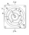
- FIG. 2is a top view of a linear actuator according to the present invention.
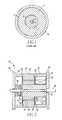
- FIG. 3is a cross sectional view taken along line 3 — 3 of FIG. 2 .
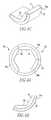
- FIG. 4is a detail view of a section of the magnet support ring. Specifically, FIG. 4A shows a plurality of sections forming a ring, FIG. 4B shows an individual segment, and FIG. 4C shows an isometric view of a segment.
- FIG. 5is a cross sectional view of an alternate embodiment incorporating a spring.
- FIGS. 2 and 3A linear actuator 10 according to the present invention is shown in FIGS. 2 and 3.
- the linear actuator 10includes a housing 20 which is formed of a top plate 21 , a top cylinder 22 , a magnet support ring 24 , a bottom cylinder 26 , and a bottom plate 28 .
- the top plate 21is coupled to the top cylinder 22 .
- the top cylinder 22is coupled to the top plate 21 on one end, and to the magnet support ring 24 or the other end.
- the magnet support ring 24is further coupled to the bottom cylinder 26 .
- Bottom cylinder 26is coupled on one end to the magnet support ring 24 and on the other end to bottom plate 28 .
- the top plate 21 and bottom plate 28are square.
- Top cylinder 22 and bottom cylinder 26are hollow, forming upper and lower cavities 23 and 27 respectively.
- Top plate 21 and bottom plate 28each has a medial opening passing therethrough. The medial openings are aligned.
- Shaft 30is slidably disposed through both medial openings.
- Shaft 30is preferably cylindrical.
- Shaft 30may have an enlarged plunger body 32 disposed between the top plate 21 and bottom plate 28 .
- the plunger body 32is preferably cylindrical and disposed about shaft 30 .
- the housing 20 and the magnet carrier 42(described below) are made of magnetically permeable material, i.e. a material with low reluctance.
- a coil assembly 35which includes a coil support 36 and wire 37 is disposed within upper cavity 23 .
- the coil support 36is a torid having a U-shaped cross section.
- Wire 37preferably 500 turns of 18-gauge magnet wire, is wrapped around coil support 36 .
- Coil assembly 35is coupled to an electric source (not shown).
- a medial openingpasses through coil support 36 .
- Shaft 30 and/or plunger body 32are slidably disposed in the coil support 36 medial opening.
- the magnet support ring 24may be any shape, however, as shown on FIGS. 4A, 4 B, and 4 C the magnet support ring 24 preferably has a cylindrical outer surface 25 and an inner surface 41 forming a plurality of flat surfaces 50 . In the preferred embodiment there are six flat surfaces 50 evenly spaced about the inner surface 41 .
- the magnet support ring 24may be formed of three 120° segments 24 a , 24 b , 24 c.
- a plurality of flat magnets 40are disposed adjacent to and contacting each inner surface 41 .
- flat magnets 40are evenly spaced angularly about shaft 30 .
- the flat magnets 40are planar and rectangular.
- the flat magnets 40are preferably made from a rare earth material such as neodymium iron boron (NdFeB), Alnico, Ferrite, Samarium Cobalt, or ceramic. Rare earth magnets tend to maintain their magnetism longer than other materials.
- the flat magnets 40are sandwiched between the inner surface 41 of magnet support ring 24 and the outer surface 43 of magnet carrier 42 .
- flat magnets 40are each perpendicular to a radius of shaft 30 .
- the outer surface 43 of magnet carrier 42has a plurality of flat surfaces 51 opposing each flat surface 50 on the magnet support ring.
- Magnet carrier 42also has a cylindrical medial opening passing therethrough.
- Shaft 30 and/or plunger body 32pass through the medial opening in magnet carrier 42 .
- Flat magnets 40are held between magnet support ring 24 and magnet carrier 42 by cylindrical caps 38 , 44 .
- Magnet cap 38is disposed between coil assembly 35 and magnet support ring 24 and magnet carrier 42 .
- Magnet cap 44is disposed in lower cavity 27 , contacting magnet support ring 24 and magnet carrier 42 . Both magnet caps 38 , 44 have medial openings.
- Shaft 30 and/or plunger body 32is slidably disposed through the medial openings in magnet caps 38 , 44 .
- the inner surface 41 of magnet support ring 24 and outer surface 43 of magnet carrier 42can be machined to have virtually no air gap between the magnets 40 and surfaces 50 , 51 .
- the average air gap between flat magnets 40 and magnet support ring 24is approximately 0.001 inch.
- the average air gap between flat magnets 40 and magnet carrier 42is approximately 0.001 inch.
- the components of the housing 20 , top plate 21 , a top cylinder 22 , a magnet support ring 24 , a bottom cylinder 26 , and a bottom plate 28each have a flat interface between the respective adjacent parts. These flat surfaces can also be machined to have virtually no air gap.
- the average total air gap between the components of the housing 20is approximately 0.001 inch or less. Because each of the surfaces 50 , 51 that contact the flat magnets 40 are also flat, the cost of manufacturing the magnet support ring 24 and magnet carrier 42 to tight tolerances is reduced.
- shaft 30may be positioned in either a first position, with plunger body 32 adjacent to top plate 21 , or a second position, with plunger body 32 adjacent to bottom plate 28 .
- Coil assembly 35my be energized by an electric source. By varying the polarity of the electric source, the current through the coil assembly 35 may travel in different directions. When the current through coil assembly 35 travels in a first direction, the coil assembly 35 creates a magnetic field which draws the shaft 30 into the first position. When the current through coil assembly 35 travels in a second direction, the coil assembly 35 creates a magnetic field which draws the shaft 30 into the second position.
- the shaft 30is maintained in either the first or second position by the sealing force created by flat magnets 40 .
- the sealing forceis created by magnetic flux passing through plunger body 32 and housing 20 . The smaller the air gap between the magnets 40 and the housing 20 and the magnet carrier 42 the greater the sealing force.
- shaft 30is biased in a first position by an external force, such as a spring (not shown) or, as shown in FIG. 5, a spring 60 may be disposed in lower cavity 27 .
- an external forcesuch as a spring (not shown) or, as shown in FIG. 5, a spring 60 may be disposed in lower cavity 27 .
- coil assembly 35When coil assembly 35 is energized, a magnetic field is created which acts on the plunger body 32 with enough force to overcome the force of the external force or spring 60 and draw the plunger body 32 to a second position adjacent to bottom plate 28 .
- the plunger body 32is held in the second position by the sealing force created by the flat magnets 40 .
Landscapes
- Engineering & Computer Science (AREA)
- Power Engineering (AREA)
- Linear Motors (AREA)
Abstract
Description
The present invention relates to a linear actuator and, more specifically, to a linear actuator which incorporates flat magnets.
A typical linear actuator of the prior art consists of a housing which encloses a cylindrical coil and a cylindrical magnet. The coil and magnet are disposed about a shaft or armature which moves axially within the housing. When the coil is not energized, the shaft is in a first position. When the coil is energized, the shaft moves axially to a second position. The sealing force, the force maintaining the shaft in either the first or second position, is created by a magnet which passes magnetic flux through the shaft. The strength of the sealing force is a function of the amount of air gap between the shaft and the magnet. Sealing force decreases as the air gap between the magnet and the shaft increases. Magnetic flux is also transferred through elements of the housing. Accordingly, the sealing force also decreases as the total air gap between the magnet and the housing components increases.
Because the amount of force exerted on the shaft is a function of the air gap between the magnets and the shaft and/or the total air gap between the magnet and the components of the housing, it is desirable to minimize the air gap. As shown in FIG. 1, prior art linear actuators use cylindrical magnets1 having a cylindrical hole therethrough. The cylindrical magnet is typically held on a magnet carrier2 which is disposed within the cylindrical hole, between the magnet and theshaft 3. The magnet is further enclosed within a protective housing4. Thus, there are three circular interfaces in linear actuators in the prior art. It is difficult, however, to machine components having tight tolerances with a cylindrical interface. As shown on FIG. 1, circular holes may be slightly elliptical or oversized, resulting in an air gap5,6,7. The sealing force created by the magnet could be increased if the air gap5,6,7 between the shaft and magnet and/or the total air gap between the magnet and housing could be reduced. Additionally, production costs could be reduced if the cylindrical interface were not used.
Therefore, there is a need for a linear actuator that reduces the air gap between the magnet carrier and the shaft.
There is a further need for a linear actuator that reduces the total air gap between the magnet and the housing components.
There is a further need for a linear actuator that is easily manufactured with a minimal air gap.
These needs and others are satisfied by the present invention, which is directed to a linear actuator, which utilizes a plurality of flat magnets spaced about the linear actuator's shaft
As with prior art linear actuators, the invention includes a housing which encloses a coil and which has a shaft passing through the coil and housing. In place of the typical cylindrical magnet, however, is a plurality of flat magnets. The flat magnets are sandwiched between a magnet support ring, which forms a portion of the housing, and a magnet carrier which is adjacent to the shaft. Because the magnets are flat, both the magnet support ring and the magnet carrier are easily machined so that the average gap between the magnet and either the magnet support ring or the magnet carrier is less than 0.001 inch. Additionally, because the magnets are flat, the present invention, requires only one circular interface, unlike the prior art which includes three circular interfaces. With a smaller air gap between the flat magnets and their support structures, the actuator provides a greater sealing force.
A full understanding of the invention can be gained from the following description of the preferred embodiments when read in conjunction with the accompanying drawings in which:
FIG. 1, prior art linear actuators showing air gaps.
FIG. 2 is a top view of a linear actuator according to the present invention.
FIG. 3 is a cross sectional view taken alongline 3—3 of FIG.2.
FIG. 4 is a detail view of a section of the magnet support ring. Specifically, FIG. 4A shows a plurality of sections forming a ring, FIG. 4B shows an individual segment, and FIG. 4C shows an isometric view of a segment.
FIG. 5 is a cross sectional view of an alternate embodiment incorporating a spring.
Alinear actuator 10 according to the present invention is shown in FIGS. 2 and 3. As shown on FIG. 3, thelinear actuator 10 includes ahousing 20 which is formed of atop plate 21, atop cylinder 22, amagnet support ring 24, abottom cylinder 26, and abottom plate 28. Thetop plate 21 is coupled to thetop cylinder 22. Thetop cylinder 22 is coupled to thetop plate 21 on one end, and to themagnet support ring 24 or the other end. Themagnet support ring 24 is further coupled to thebottom cylinder 26.Bottom cylinder 26 is coupled on one end to themagnet support ring 24 and on the other end tobottom plate 28. In the preferred embodiment, thetop plate 21 andbottom plate 28 are square.Top cylinder 22 andbottom cylinder 26 are hollow, forming upper andlower cavities 23 and27 respectively.Top plate 21 andbottom plate 28 each has a medial opening passing therethrough. The medial openings are aligned. Shaft30 is slidably disposed through both medial openings. Shaft30 is preferably cylindrical.Shaft 30 may have an enlargedplunger body 32 disposed between thetop plate 21 andbottom plate 28. Theplunger body 32 is preferably cylindrical and disposed aboutshaft 30. Thehousing 20 and the magnet carrier42 (described below) are made of magnetically permeable material, i.e. a material with low reluctance.
Acoil assembly 35, which includes acoil support 36 andwire 37 is disposed withinupper cavity 23. Thecoil support 36 is a torid having a U-shaped cross section.Wire 37, preferably500 turns of 18-gauge magnet wire, is wrapped aroundcoil support 36.Coil assembly 35 is coupled to an electric source (not shown). A medial opening passes throughcoil support 36. Shaft30 and/orplunger body 32 are slidably disposed in thecoil support 36 medial opening.
Themagnet support ring 24 may be any shape, however, as shown on FIGS. 4A,4B, and4C themagnet support ring 24 preferably has a cylindricalouter surface 25 and aninner surface 41 forming a plurality offlat surfaces 50. In the preferred embodiment there are sixflat surfaces 50 evenly spaced about theinner surface 41. Themagnet support ring 24 may be formed of three 120°segments
A plurality offlat magnets 40 are disposed adjacent to and contacting eachinner surface 41. Preferablyflat magnets 40 are evenly spaced angularly aboutshaft 30. Theflat magnets 40 are planar and rectangular. Theflat magnets 40 are preferably made from a rare earth material such as neodymium iron boron (NdFeB), Alnico, Ferrite, Samarium Cobalt, or ceramic. Rare earth magnets tend to maintain their magnetism longer than other materials. Theflat magnets 40 are sandwiched between theinner surface 41 ofmagnet support ring 24 and the outer surface43 ofmagnet carrier 42. Preferably,flat magnets 40 are each perpendicular to a radius ofshaft 30. The outer surface43 ofmagnet carrier 42 has a plurality offlat surfaces 51 opposing eachflat surface 50 on the magnet support ring.Magnet carrier 42 also has a cylindrical medial opening passing therethrough.Shaft 30 and/orplunger body 32 pass through the medial opening inmagnet carrier 42.Flat magnets 40 are held betweenmagnet support ring 24 andmagnet carrier 42 bycylindrical caps Magnet cap 38 is disposed betweencoil assembly 35 andmagnet support ring 24 andmagnet carrier 42.Magnet cap 44 is disposed in lower cavity27, contactingmagnet support ring 24 andmagnet carrier 42. Both magnet caps38,44 have medial openings.Shaft 30 and/orplunger body 32 is slidably disposed through the medial openings in magnet caps38,44.
Because themagnets 40 are flat, theinner surface 41 ofmagnet support ring 24 and outer surface43 ofmagnet carrier 42 can be machined to have virtually no air gap between themagnets 40 and surfaces50,51. The average air gap betweenflat magnets 40 andmagnet support ring 24 is approximately 0.001 inch. The average air gap betweenflat magnets 40 andmagnet carrier 42 is approximately 0.001 inch. Additionally, the components of thehousing 20,top plate 21, atop cylinder 22, amagnet support ring 24, abottom cylinder 26, and abottom plate 28, each have a flat interface between the respective adjacent parts. These flat surfaces can also be machined to have virtually no air gap. The average total air gap between the components of thehousing 20 is approximately 0.001 inch or less. Because each of thesurfaces flat magnets 40 are also flat, the cost of manufacturing themagnet support ring 24 andmagnet carrier 42 to tight tolerances is reduced.
In operation,shaft 30 may be positioned in either a first position, withplunger body 32 adjacent totop plate 21, or a second position, withplunger body 32 adjacent tobottom plate 28.Coil assembly 35 my be energized by an electric source. By varying the polarity of the electric source, the current through thecoil assembly 35 may travel in different directions. When the current throughcoil assembly 35 travels in a first direction, thecoil assembly 35 creates a magnetic field which draws theshaft 30 into the first position. When the current throughcoil assembly 35 travels in a second direction, thecoil assembly 35 creates a magnetic field which draws theshaft 30 into the second position. When the coil in not energized, theshaft 30 is maintained in either the first or second position by the sealing force created byflat magnets 40. The sealing force is created by magnetic flux passing throughplunger body 32 andhousing 20. The smaller the air gap between themagnets 40 and thehousing 20 and themagnet carrier 42 the greater the sealing force.
In an alternate embodiment,shaft 30 is biased in a first position by an external force, such as a spring (not shown) or, as shown in FIG. 5, aspring 60 may be disposed in lower cavity27. Whencoil assembly 35 is energized, a magnetic field is created which acts on theplunger body 32 with enough force to overcome the force of the external force orspring 60 and draw theplunger body 32 to a second position adjacent tobottom plate 28. Theplunger body 32 is held in the second position by the sealing force created by theflat magnets 40.
While specific embodiments of the invention have been described in detail, it will be appreciated by those skilled in the art that various modifications and alternatives to those details could be developed in light of the overall teachings of the disclosure. Accordingly, the particular arrangements disclosed are meant to be illustrative only and not limiting as to the scope of invention which is to be given the full breadth of the claims appended and any and all equivalents thereof.
Claims (22)
1. A linear actuator comprising:
a housing assembly;
a shaft assembly slidably disposed within said housing, said shaft assembly having two opposing ends, said ends protruding from opposite sides of said housing;
a plurality of flat magnets disposed within said housing about said shaft;
a magnet carrier disposed about said shaft assembly;
said magnet carrier having an exterior side; said exterior side having a plurality of flat surfaces;
said flat magnets are supported by said magnet carrier flat surfaces; and
wherein the average air gap between said magnets and said magnet carrier is less than 0.001 inch.
2. The linear actuator ofclaim 1 wherein:
a portion of said housing assembly is a magnet support ring having an interior side, said magnet support ring interior side having a plurality of flat surfaces aligned with said flat surfaces on said exterior side of said magnet carrier; and
said magnets disposed between said magnet carrier exterior side and said magnet support ring interior side.
3. The linear actuator ofclaim 2 , wherein the average air gap between said magnets and said magnet support ring is less than about 0.001 inch.
4. The linear actuator ofclaim 3 , wherein said flat magnets are evenly angularly distributed about said shaft.
5. The linear actuator ofclaim 4 , wherein said flat magnets are each oriented perpendicular to a radius of said shaft.
6. The linear actuator ofclaim 5 , wherein said housing assembly further includes:
a top plate;
a top cylinder;
a bottom cylinder;
a bottom plate;
said top plate adjacent to said top cylinder;
said top cylinder disposed between said top plate and said magnet support ring;
said magnet support ring disposed between said top cylinder and said bottom cylinder;
said bottom cylinder disposed between said magnet support ring and said bottom plate;
said bottom plate disposed adjacent to said bottom cylinder.
7. The linear actuator ofclaim 6 wherein the average total air gap between said top plate, said top cylinder, said magnet support ring, said bottom cylinder and said bottom plate is less than about 0.001 inch.
8. The linear actuator ofclaim 7 , wherein said plurality of magnets comprises 6 magnets.
9. The linear actuator ofclaim 8 , wherein said magnet carrier exterior side has six flat sides.
10. The linear actuator ofclaim 9 , wherein said magnet support ring has an outer side, said outer side having a cylindrical cross-section substantially the same diameter as said top cylinder and said bottom cylinder, said interior side having six flat sides.
11. The linear actuator ofclaim 10 , wherein said flat magnets are made from neodymium iron boron.
12. The linear actuator ofclaim 10 , wherein said flat are made from a rare earth material selected from the group consisting of Alnico, Ferrite, Samarium Cobalt, and ceramic.
13. The linear actuator ofclaim 10 , wherein said housing assembly includes:
a coil assembly disposed in said housing encircling said shaft;
said shaft is movable in an axial direction between a first position and a second position; and wherein
energizing said coil with a current having a first polarity drives said shaft to said first position.
14. The linear actuator ofclaim 13 , wherein said housing assembly includes:
a spring disposed within said housing;
said shaft is biased in said first position by said spring.
15. The linear actuator ofclaim 13 , wherein energizing said coil with a current having a second polarity drives said shaft to said second position.
16. The linear actuator ofclaim 2 , wherein said flat magnets are made from neodymium iron boron.
17. The linear actuator ofclaim 2 , wherein said flat magnets are made from a rare earth material selected from the group consisting of Alnico, Ferrite, Samarium Cobalt, and ceramic.
18. The linear actuator ofclaim 2 , wherein said housing assembly includes:
a coil assembly disposed in said housing encircling said shaft;
an electric source;
said coil is coupled to said electric source; and
said shaft is movable in an axial direction between a first position and a second position; and
energizing said coil biases said shaft in said second position.
19. The linear actuator ofclaim 2 , wherein said housing assembly includes:
a spring;
said shaft is biased in said first position by said spring.
20. The linear actuator ofclaim 19 , wherein the average air gap between said magnets and said magnet support ring is less than about 0.001 inch.
21. The linear actuator ofclaim 20 , wherein said flat magnets are evenly angularly distributed about said shaft.
22. The linear actuator ofclaim 21 , wherein said flat magnets are each oriented perpendicular to a radius of said shaft.
Priority Applications (1)
| Application Number | Priority Date | Filing Date | Title |
|---|---|---|---|
| US09/544,862US6365993B1 (en) | 2000-04-07 | 2000-04-07 | Round linear actuator utilizing flat permanent magnets |
Applications Claiming Priority (1)
| Application Number | Priority Date | Filing Date | Title |
|---|---|---|---|
| US09/544,862US6365993B1 (en) | 2000-04-07 | 2000-04-07 | Round linear actuator utilizing flat permanent magnets |
Publications (1)
| Publication Number | Publication Date |
|---|---|
| US6365993B1true US6365993B1 (en) | 2002-04-02 |
Family
ID=24173906
Family Applications (1)
| Application Number | Title | Priority Date | Filing Date |
|---|---|---|---|
| US09/544,862Expired - LifetimeUS6365993B1 (en) | 2000-04-07 | 2000-04-07 | Round linear actuator utilizing flat permanent magnets |
Country Status (1)
| Country | Link |
|---|---|
| US (1) | US6365993B1 (en) |
Cited By (11)
| Publication number | Priority date | Publication date | Assignee | Title |
|---|---|---|---|---|
| US20030102723A1 (en)* | 2001-10-05 | 2003-06-05 | Canon Kabushiki Kaisha | Linear motor, stage apparatus, and exposure apparatus |
| USD482707S1 (en) | 2002-10-01 | 2003-11-25 | Tri-Tech, Inc. | Linear actuator shaft |
| WO2003107515A1 (en)* | 2002-06-18 | 2003-12-24 | 株式会社三協精機製作所 | Linear actuator, and pump and compressor devices using the actuator |
| US6930271B1 (en) | 2004-08-13 | 2005-08-16 | Eaton Corporation | Circuit interrupter including linear actuator and manual pivot member |
| US20070166022A1 (en)* | 2006-01-19 | 2007-07-19 | Asustek Computer Inc. | Camera module and electric device using the same |
| US20070252667A1 (en)* | 2006-05-01 | 2007-11-01 | Eaton Corporation | Manual opening device and electrical switching apparatus employing the same |
| US20090212889A1 (en)* | 2005-05-20 | 2009-08-27 | Elliot Brooks | Eddy current inductive drive electromechanical linear actuator and switching arrangement |
| US8922070B2 (en) | 2010-10-22 | 2014-12-30 | Linear Labs, Inc. | Magnetic motor |
| US9219962B2 (en) | 2012-09-03 | 2015-12-22 | Linear Labs, Inc. | Transducer and method of operation |
| US9325232B1 (en) | 2010-07-22 | 2016-04-26 | Linear Labs, Inc. | Method and apparatus for power generation |
| US9936300B2 (en) | 2012-09-03 | 2018-04-03 | Linear Labs, Inc | Transducer and method of operation |
Citations (7)
| Publication number | Priority date | Publication date | Assignee | Title |
|---|---|---|---|---|
| US4315197A (en)* | 1980-02-07 | 1982-02-09 | The United States Of America As Represented By The Administrator Of The National Aeronautics And Space Administration | Linear magnetic motor/generator |
| US4387935A (en)* | 1980-12-08 | 1983-06-14 | The United States Of America As Represented By The Administrator Of The National Aeronautics And Space Administration | Linear magnetic bearing |
| US4439699A (en)* | 1982-01-18 | 1984-03-27 | International Business Machines Corporation | Linear moving coil actuator |
| US4883994A (en)* | 1985-10-28 | 1989-11-28 | Sony Corporation | Linear motor |
| US5471100A (en)* | 1993-03-30 | 1995-11-28 | Sony Corporation | Linear electromagnetic driving apparatus and use of same for lens adjustment |
| US5952742A (en)* | 1995-02-03 | 1999-09-14 | Krauss-Maffei Ag | Synchronous linear motor with improved means for positioning and fastening permanent magnets |
| US6066998A (en)* | 1996-09-12 | 2000-05-23 | Massachusetts Institute Of Technology | Magnetic actuator with long travel in one direction |
- 2000
- 2000-04-07USUS09/544,862patent/US6365993B1/ennot_activeExpired - Lifetime
Patent Citations (7)
| Publication number | Priority date | Publication date | Assignee | Title |
|---|---|---|---|---|
| US4315197A (en)* | 1980-02-07 | 1982-02-09 | The United States Of America As Represented By The Administrator Of The National Aeronautics And Space Administration | Linear magnetic motor/generator |
| US4387935A (en)* | 1980-12-08 | 1983-06-14 | The United States Of America As Represented By The Administrator Of The National Aeronautics And Space Administration | Linear magnetic bearing |
| US4439699A (en)* | 1982-01-18 | 1984-03-27 | International Business Machines Corporation | Linear moving coil actuator |
| US4883994A (en)* | 1985-10-28 | 1989-11-28 | Sony Corporation | Linear motor |
| US5471100A (en)* | 1993-03-30 | 1995-11-28 | Sony Corporation | Linear electromagnetic driving apparatus and use of same for lens adjustment |
| US5952742A (en)* | 1995-02-03 | 1999-09-14 | Krauss-Maffei Ag | Synchronous linear motor with improved means for positioning and fastening permanent magnets |
| US6066998A (en)* | 1996-09-12 | 2000-05-23 | Massachusetts Institute Of Technology | Magnetic actuator with long travel in one direction |
Cited By (27)
| Publication number | Priority date | Publication date | Assignee | Title |
|---|---|---|---|---|
| US6864602B2 (en)* | 2001-10-05 | 2005-03-08 | Canon Kabushiki Kaisha | Linear motor, stage apparatus, and exposure apparatus |
| US20030102723A1 (en)* | 2001-10-05 | 2003-06-05 | Canon Kabushiki Kaisha | Linear motor, stage apparatus, and exposure apparatus |
| WO2003107515A1 (en)* | 2002-06-18 | 2003-12-24 | 株式会社三協精機製作所 | Linear actuator, and pump and compressor devices using the actuator |
| US6980072B2 (en) | 2002-06-18 | 2005-12-27 | Nidec Sankyo Corporation | Linear actuator, and pump and compressor devices using the actuator |
| CN100440694C (en)* | 2002-06-18 | 2008-12-03 | 日本电产三协株式会社 | Linear actuator, pump unit and compressor unit using it |
| USD482707S1 (en) | 2002-10-01 | 2003-11-25 | Tri-Tech, Inc. | Linear actuator shaft |
| US20110068884A1 (en)* | 2004-05-20 | 2011-03-24 | Powerpath Technologies Llc | Electromechanical actuator |
| US8134438B2 (en) | 2004-05-20 | 2012-03-13 | Powerpath Technologies Llc | Electromechanical actuator |
| US7777600B2 (en) | 2004-05-20 | 2010-08-17 | Powerpath Technologies Llc | Eddy current inductive drive electromechanical liner actuator and switching arrangement |
| US6930271B1 (en) | 2004-08-13 | 2005-08-16 | Eaton Corporation | Circuit interrupter including linear actuator and manual pivot member |
| US8134437B2 (en) | 2005-05-20 | 2012-03-13 | Powerpath Technologies Llc | Eddy current inductive drive electromechanical linear actuator and switching arrangement |
| US20090212889A1 (en)* | 2005-05-20 | 2009-08-27 | Elliot Brooks | Eddy current inductive drive electromechanical linear actuator and switching arrangement |
| US20070166022A1 (en)* | 2006-01-19 | 2007-07-19 | Asustek Computer Inc. | Camera module and electric device using the same |
| US20070252667A1 (en)* | 2006-05-01 | 2007-11-01 | Eaton Corporation | Manual opening device and electrical switching apparatus employing the same |
| US7545245B2 (en) | 2006-05-01 | 2009-06-09 | Eaton Corporation | Manual opening device and electrical switching apparatus employing the same |
| US11218067B2 (en) | 2010-07-22 | 2022-01-04 | Linear Labs, Inc. | Method and apparatus for power generation |
| US9325232B1 (en) | 2010-07-22 | 2016-04-26 | Linear Labs, Inc. | Method and apparatus for power generation |
| US10587178B2 (en) | 2010-07-22 | 2020-03-10 | Linear Labs, Inc. | Method and apparatus for power generation |
| US8922070B2 (en) | 2010-10-22 | 2014-12-30 | Linear Labs, Inc. | Magnetic motor |
| US9325219B2 (en) | 2010-10-22 | 2016-04-26 | Linear Labs, Inc. | Magnetic motor and method of use |
| US20230216370A1 (en)* | 2010-10-22 | 2023-07-06 | Linear Labs, Inc. | Magnetic motor and method of use |
| US10291096B2 (en) | 2010-10-22 | 2019-05-14 | Linear Labs, LLC | Magnetic motor and method of use |
| US20220123625A1 (en)* | 2010-10-22 | 2022-04-21 | Linear Labs, Inc. | Magnetic motor and method of use |
| US11165307B2 (en)* | 2010-10-22 | 2021-11-02 | Linear Labs, Inc. | Magnetic motor and method of use |
| US9219962B2 (en) | 2012-09-03 | 2015-12-22 | Linear Labs, Inc. | Transducer and method of operation |
| US10575100B2 (en) | 2012-09-03 | 2020-02-25 | Linear Labs, LLC | Transducer and method of operation |
| US9936300B2 (en) | 2012-09-03 | 2018-04-03 | Linear Labs, Inc | Transducer and method of operation |
Similar Documents
| Publication | Publication Date | Title |
|---|---|---|
| CN101010755B (en) | Electromagnetic actuator | |
| US5434549A (en) | Moving magnet-type actuator | |
| US7382067B2 (en) | Linear actuator | |
| US6365993B1 (en) | Round linear actuator utilizing flat permanent magnets | |
| ES2241025T3 (en) | MAGNETIC ACTUATOR. | |
| CA2351144A1 (en) | Electromagnetic linear oscillator | |
| EP1513176A3 (en) | Linear switch actuator | |
| US6489870B1 (en) | Solenoid with improved pull force | |
| JP2001520860A (en) | Improved linear actuator | |
| US6028499A (en) | Monophase, short travel, electromagnetic actuator having a good electric power/force ratio | |
| CA1192249A (en) | Electro-magnet equipped with a moving system including a permanent magnet and designed for monostable operation | |
| JPH0638486A (en) | Movable magnet type actuator | |
| EP0829887A3 (en) | Magnetic actuator with long travel in one direction | |
| CN106716565B (en) | Electromagnetic adjustment equipment | |
| CN203588789U (en) | Actuator | |
| JPS61285055A (en) | Electromagnetic actuator | |
| JP2006222438A (en) | Electromagnet and operation mechanism of switchgear using the same | |
| US6700230B1 (en) | Linear actuator | |
| US7202578B2 (en) | Electromagnetic drive device | |
| JPH079081U (en) | Movable magnet type actuator | |
| US20020117904A1 (en) | Long stroke linear voice coil actuator with the proportional solenoid type characteristic | |
| WO1981003575A1 (en) | Linear solenoid device | |
| US6831538B2 (en) | Linear voice coil actuator as a controllable electromagnetic compression spring | |
| JPH0644385U (en) | Movable magnet type actuator | |
| JPH02161702A (en) | Actuator actuating movable |
Legal Events
| Date | Code | Title | Description |
|---|---|---|---|
| AS | Assignment | Owner name:EATON CORPORATION, OHIO Free format text:ASSIGNMENT OF ASSIGNORS INTEREST;ASSIGNORS:CALHOON, GLENN ARTHUR;BOTTEGAL, PAUL THOMAS;RINEFIERD, ROBERT JOSEPH;AND OTHERS;REEL/FRAME:010744/0386 Effective date:20000331 | |
| FEPP | Fee payment procedure | Free format text:PAYOR NUMBER ASSIGNED (ORIGINAL EVENT CODE: ASPN); ENTITY STATUS OF PATENT OWNER: LARGE ENTITY | |
| STCF | Information on status: patent grant | Free format text:PATENTED CASE | |
| FPAY | Fee payment | Year of fee payment:4 | |
| FPAY | Fee payment | Year of fee payment:8 | |
| FPAY | Fee payment | Year of fee payment:12 | |
| AS | Assignment | Owner name:EATON INTELLIGENT POWER LIMITED, IRELAND Free format text:ASSIGNMENT OF ASSIGNORS INTEREST;ASSIGNOR:EATON CORPORATION;REEL/FRAME:048855/0626 Effective date:20171231 |