US6364880B1 - Spinal implant with bone screws - Google Patents
Spinal implant with bone screwsDownload PDFInfo
- Publication number
- US6364880B1 US6364880B1US09/563,705US56370500AUS6364880B1US 6364880 B1US6364880 B1US 6364880B1US 56370500 AUS56370500 AUS 56370500AUS 6364880 B1US6364880 B1US 6364880B1
- Authority
- US
- United States
- Prior art keywords
- implant
- bone
- bone screws
- adjacent vertebral
- spine
- Prior art date
- Legal status (The legal status is an assumption and is not a legal conclusion. Google has not performed a legal analysis and makes no representation as to the accuracy of the status listed.)
- Expired - Lifetime
Links
Images


Classifications
- A—HUMAN NECESSITIES
- A61—MEDICAL OR VETERINARY SCIENCE; HYGIENE
- A61B—DIAGNOSIS; SURGERY; IDENTIFICATION
- A61B17/00—Surgical instruments, devices or methods
- A61B17/02—Surgical instruments, devices or methods for holding wounds open, e.g. retractors; Tractors
- A61B17/025—Joint distractors
- A—HUMAN NECESSITIES
- A61—MEDICAL OR VETERINARY SCIENCE; HYGIENE
- A61B—DIAGNOSIS; SURGERY; IDENTIFICATION
- A61B17/00—Surgical instruments, devices or methods
- A61B17/064—Surgical staples, i.e. penetrating the tissue
- A61B17/0642—Surgical staples, i.e. penetrating the tissue for bones, e.g. for osteosynthesis or connecting tendon to bone
- A—HUMAN NECESSITIES
- A61—MEDICAL OR VETERINARY SCIENCE; HYGIENE
- A61B—DIAGNOSIS; SURGERY; IDENTIFICATION
- A61B17/00—Surgical instruments, devices or methods
- A61B17/16—Instruments for performing osteoclasis; Drills or chisels for bones; Trepans
- A61B17/17—Guides or aligning means for drills, mills, pins or wires
- A61B17/1739—Guides or aligning means for drills, mills, pins or wires specially adapted for particular parts of the body
- A61B17/1757—Guides or aligning means for drills, mills, pins or wires specially adapted for particular parts of the body for the spine
- A—HUMAN NECESSITIES
- A61—MEDICAL OR VETERINARY SCIENCE; HYGIENE
- A61B—DIAGNOSIS; SURGERY; IDENTIFICATION
- A61B17/00—Surgical instruments, devices or methods
- A61B17/56—Surgical instruments or methods for treatment of bones or joints; Devices specially adapted therefor
- A61B17/58—Surgical instruments or methods for treatment of bones or joints; Devices specially adapted therefor for osteosynthesis, e.g. bone plates, screws or setting implements
- A61B17/88—Osteosynthesis instruments; Methods or means for implanting or extracting internal or external fixation devices
- A61B17/92—Impactors or extractors, e.g. for removing intramedullary devices
- A—HUMAN NECESSITIES
- A61—MEDICAL OR VETERINARY SCIENCE; HYGIENE
- A61F—FILTERS IMPLANTABLE INTO BLOOD VESSELS; PROSTHESES; DEVICES PROVIDING PATENCY TO, OR PREVENTING COLLAPSING OF, TUBULAR STRUCTURES OF THE BODY, e.g. STENTS; ORTHOPAEDIC, NURSING OR CONTRACEPTIVE DEVICES; FOMENTATION; TREATMENT OR PROTECTION OF EYES OR EARS; BANDAGES, DRESSINGS OR ABSORBENT PADS; FIRST-AID KITS
- A61F2/00—Filters implantable into blood vessels; Prostheses, i.e. artificial substitutes or replacements for parts of the body; Appliances for connecting them with the body; Devices providing patency to, or preventing collapsing of, tubular structures of the body, e.g. stents
- A61F2/02—Prostheses implantable into the body
- A61F2/30—Joints
- A61F2/44—Joints for the spine, e.g. vertebrae, spinal discs
- A61F2/4455—Joints for the spine, e.g. vertebrae, spinal discs for the fusion of spinal bodies, e.g. intervertebral fusion of adjacent spinal bodies, e.g. fusion cages
- A61F2/446—Joints for the spine, e.g. vertebrae, spinal discs for the fusion of spinal bodies, e.g. intervertebral fusion of adjacent spinal bodies, e.g. fusion cages having a circular or elliptical cross-section substantially parallel to the axis of the spine, e.g. cylinders or frustocones
- A—HUMAN NECESSITIES
- A61—MEDICAL OR VETERINARY SCIENCE; HYGIENE
- A61B—DIAGNOSIS; SURGERY; IDENTIFICATION
- A61B17/00—Surgical instruments, devices or methods
- A61B17/56—Surgical instruments or methods for treatment of bones or joints; Devices specially adapted therefor
- A61B17/58—Surgical instruments or methods for treatment of bones or joints; Devices specially adapted therefor for osteosynthesis, e.g. bone plates, screws or setting implements
- A61B17/68—Internal fixation devices, including fasteners and spinal fixators, even if a part thereof projects from the skin
- A61B17/70—Spinal positioners or stabilisers, e.g. stabilisers comprising fluid filler in an implant
- A61B17/7059—Cortical plates
- A—HUMAN NECESSITIES
- A61—MEDICAL OR VETERINARY SCIENCE; HYGIENE
- A61B—DIAGNOSIS; SURGERY; IDENTIFICATION
- A61B17/00—Surgical instruments, devices or methods
- A61B17/56—Surgical instruments or methods for treatment of bones or joints; Devices specially adapted therefor
- A61B17/58—Surgical instruments or methods for treatment of bones or joints; Devices specially adapted therefor for osteosynthesis, e.g. bone plates, screws or setting implements
- A61B17/68—Internal fixation devices, including fasteners and spinal fixators, even if a part thereof projects from the skin
- A61B17/80—Cortical plates, i.e. bone plates; Instruments for holding or positioning cortical plates, or for compressing bones attached to cortical plates
- A61B17/809—Cortical plates, i.e. bone plates; Instruments for holding or positioning cortical plates, or for compressing bones attached to cortical plates with bone-penetrating elements, e.g. blades or prongs
- A—HUMAN NECESSITIES
- A61—MEDICAL OR VETERINARY SCIENCE; HYGIENE
- A61B—DIAGNOSIS; SURGERY; IDENTIFICATION
- A61B17/00—Surgical instruments, devices or methods
- A61B17/56—Surgical instruments or methods for treatment of bones or joints; Devices specially adapted therefor
- A61B17/58—Surgical instruments or methods for treatment of bones or joints; Devices specially adapted therefor for osteosynthesis, e.g. bone plates, screws or setting implements
- A61B17/68—Internal fixation devices, including fasteners and spinal fixators, even if a part thereof projects from the skin
- A61B17/84—Fasteners therefor or fasteners being internal fixation devices
- A61B17/86—Pins or screws or threaded wires; nuts therefor
- A61B17/8665—Nuts
- A—HUMAN NECESSITIES
- A61—MEDICAL OR VETERINARY SCIENCE; HYGIENE
- A61B—DIAGNOSIS; SURGERY; IDENTIFICATION
- A61B17/00—Surgical instruments, devices or methods
- A61B2017/00004—(bio)absorbable, (bio)resorbable or resorptive
- A—HUMAN NECESSITIES
- A61—MEDICAL OR VETERINARY SCIENCE; HYGIENE
- A61B—DIAGNOSIS; SURGERY; IDENTIFICATION
- A61B17/00—Surgical instruments, devices or methods
- A61B17/02—Surgical instruments, devices or methods for holding wounds open, e.g. retractors; Tractors
- A61B17/025—Joint distractors
- A61B2017/0256—Joint distractors for the spine
- A—HUMAN NECESSITIES
- A61—MEDICAL OR VETERINARY SCIENCE; HYGIENE
- A61B—DIAGNOSIS; SURGERY; IDENTIFICATION
- A61B17/00—Surgical instruments, devices or methods
- A61B17/064—Surgical staples, i.e. penetrating the tissue
- A61B2017/0641—Surgical staples, i.e. penetrating the tissue having at least three legs as part of one single body
- A—HUMAN NECESSITIES
- A61—MEDICAL OR VETERINARY SCIENCE; HYGIENE
- A61B—DIAGNOSIS; SURGERY; IDENTIFICATION
- A61B17/00—Surgical instruments, devices or methods
- A61B17/064—Surgical staples, i.e. penetrating the tissue
- A61B2017/0647—Surgical staples, i.e. penetrating the tissue having one single leg, e.g. tacks
- A61B2017/0648—Surgical staples, i.e. penetrating the tissue having one single leg, e.g. tacks threaded, e.g. tacks with a screw thread
- A—HUMAN NECESSITIES
- A61—MEDICAL OR VETERINARY SCIENCE; HYGIENE
- A61F—FILTERS IMPLANTABLE INTO BLOOD VESSELS; PROSTHESES; DEVICES PROVIDING PATENCY TO, OR PREVENTING COLLAPSING OF, TUBULAR STRUCTURES OF THE BODY, e.g. STENTS; ORTHOPAEDIC, NURSING OR CONTRACEPTIVE DEVICES; FOMENTATION; TREATMENT OR PROTECTION OF EYES OR EARS; BANDAGES, DRESSINGS OR ABSORBENT PADS; FIRST-AID KITS
- A61F2/00—Filters implantable into blood vessels; Prostheses, i.e. artificial substitutes or replacements for parts of the body; Appliances for connecting them with the body; Devices providing patency to, or preventing collapsing of, tubular structures of the body, e.g. stents
- A61F2/02—Prostheses implantable into the body
- A61F2/30—Joints
- A61F2/30767—Special external or bone-contacting surface, e.g. coating for improving bone ingrowth
- A—HUMAN NECESSITIES
- A61—MEDICAL OR VETERINARY SCIENCE; HYGIENE
- A61F—FILTERS IMPLANTABLE INTO BLOOD VESSELS; PROSTHESES; DEVICES PROVIDING PATENCY TO, OR PREVENTING COLLAPSING OF, TUBULAR STRUCTURES OF THE BODY, e.g. STENTS; ORTHOPAEDIC, NURSING OR CONTRACEPTIVE DEVICES; FOMENTATION; TREATMENT OR PROTECTION OF EYES OR EARS; BANDAGES, DRESSINGS OR ABSORBENT PADS; FIRST-AID KITS
- A61F2/00—Filters implantable into blood vessels; Prostheses, i.e. artificial substitutes or replacements for parts of the body; Appliances for connecting them with the body; Devices providing patency to, or preventing collapsing of, tubular structures of the body, e.g. stents
- A61F2/02—Prostheses implantable into the body
- A61F2/30—Joints
- A61F2/3094—Designing or manufacturing processes
- A61F2/30965—Reinforcing the prosthesis by embedding particles or fibres during moulding or dipping
- A—HUMAN NECESSITIES
- A61—MEDICAL OR VETERINARY SCIENCE; HYGIENE
- A61F—FILTERS IMPLANTABLE INTO BLOOD VESSELS; PROSTHESES; DEVICES PROVIDING PATENCY TO, OR PREVENTING COLLAPSING OF, TUBULAR STRUCTURES OF THE BODY, e.g. STENTS; ORTHOPAEDIC, NURSING OR CONTRACEPTIVE DEVICES; FOMENTATION; TREATMENT OR PROTECTION OF EYES OR EARS; BANDAGES, DRESSINGS OR ABSORBENT PADS; FIRST-AID KITS
- A61F2/00—Filters implantable into blood vessels; Prostheses, i.e. artificial substitutes or replacements for parts of the body; Appliances for connecting them with the body; Devices providing patency to, or preventing collapsing of, tubular structures of the body, e.g. stents
- A61F2/02—Prostheses implantable into the body
- A61F2/30—Joints
- A61F2/44—Joints for the spine, e.g. vertebrae, spinal discs
- A61F2/442—Intervertebral or spinal discs, e.g. resilient
- A—HUMAN NECESSITIES
- A61—MEDICAL OR VETERINARY SCIENCE; HYGIENE
- A61F—FILTERS IMPLANTABLE INTO BLOOD VESSELS; PROSTHESES; DEVICES PROVIDING PATENCY TO, OR PREVENTING COLLAPSING OF, TUBULAR STRUCTURES OF THE BODY, e.g. STENTS; ORTHOPAEDIC, NURSING OR CONTRACEPTIVE DEVICES; FOMENTATION; TREATMENT OR PROTECTION OF EYES OR EARS; BANDAGES, DRESSINGS OR ABSORBENT PADS; FIRST-AID KITS
- A61F2/00—Filters implantable into blood vessels; Prostheses, i.e. artificial substitutes or replacements for parts of the body; Appliances for connecting them with the body; Devices providing patency to, or preventing collapsing of, tubular structures of the body, e.g. stents
- A61F2/02—Prostheses implantable into the body
- A61F2/30—Joints
- A61F2/46—Special tools for implanting artificial joints
- A61F2/4603—Special tools for implanting artificial joints for insertion or extraction of endoprosthetic joints or of accessories thereof
- A61F2/4611—Special tools for implanting artificial joints for insertion or extraction of endoprosthetic joints or of accessories thereof of spinal prostheses
- A—HUMAN NECESSITIES
- A61—MEDICAL OR VETERINARY SCIENCE; HYGIENE
- A61F—FILTERS IMPLANTABLE INTO BLOOD VESSELS; PROSTHESES; DEVICES PROVIDING PATENCY TO, OR PREVENTING COLLAPSING OF, TUBULAR STRUCTURES OF THE BODY, e.g. STENTS; ORTHOPAEDIC, NURSING OR CONTRACEPTIVE DEVICES; FOMENTATION; TREATMENT OR PROTECTION OF EYES OR EARS; BANDAGES, DRESSINGS OR ABSORBENT PADS; FIRST-AID KITS
- A61F2/00—Filters implantable into blood vessels; Prostheses, i.e. artificial substitutes or replacements for parts of the body; Appliances for connecting them with the body; Devices providing patency to, or preventing collapsing of, tubular structures of the body, e.g. stents
- A61F2/02—Prostheses implantable into the body
- A61F2/30—Joints
- A61F2002/30001—Additional features of subject-matter classified in A61F2/28, A61F2/30 and subgroups thereof
- A61F2002/30003—Material related properties of the prosthesis or of a coating on the prosthesis
- A61F2002/3006—Properties of materials and coating materials
- A61F2002/30062—(bio)absorbable, biodegradable, bioerodable, (bio)resorbable, resorptive
- A—HUMAN NECESSITIES
- A61—MEDICAL OR VETERINARY SCIENCE; HYGIENE
- A61F—FILTERS IMPLANTABLE INTO BLOOD VESSELS; PROSTHESES; DEVICES PROVIDING PATENCY TO, OR PREVENTING COLLAPSING OF, TUBULAR STRUCTURES OF THE BODY, e.g. STENTS; ORTHOPAEDIC, NURSING OR CONTRACEPTIVE DEVICES; FOMENTATION; TREATMENT OR PROTECTION OF EYES OR EARS; BANDAGES, DRESSINGS OR ABSORBENT PADS; FIRST-AID KITS
- A61F2/00—Filters implantable into blood vessels; Prostheses, i.e. artificial substitutes or replacements for parts of the body; Appliances for connecting them with the body; Devices providing patency to, or preventing collapsing of, tubular structures of the body, e.g. stents
- A61F2/02—Prostheses implantable into the body
- A61F2/30—Joints
- A61F2002/30001—Additional features of subject-matter classified in A61F2/28, A61F2/30 and subgroups thereof
- A61F2002/30108—Shapes
- A61F2002/30199—Three-dimensional shapes
- A61F2002/30224—Three-dimensional shapes cylindrical
- A61F2002/30235—Three-dimensional shapes cylindrical tubular, e.g. sleeves
- A—HUMAN NECESSITIES
- A61—MEDICAL OR VETERINARY SCIENCE; HYGIENE
- A61F—FILTERS IMPLANTABLE INTO BLOOD VESSELS; PROSTHESES; DEVICES PROVIDING PATENCY TO, OR PREVENTING COLLAPSING OF, TUBULAR STRUCTURES OF THE BODY, e.g. STENTS; ORTHOPAEDIC, NURSING OR CONTRACEPTIVE DEVICES; FOMENTATION; TREATMENT OR PROTECTION OF EYES OR EARS; BANDAGES, DRESSINGS OR ABSORBENT PADS; FIRST-AID KITS
- A61F2/00—Filters implantable into blood vessels; Prostheses, i.e. artificial substitutes or replacements for parts of the body; Appliances for connecting them with the body; Devices providing patency to, or preventing collapsing of, tubular structures of the body, e.g. stents
- A61F2/02—Prostheses implantable into the body
- A61F2/30—Joints
- A61F2002/30001—Additional features of subject-matter classified in A61F2/28, A61F2/30 and subgroups thereof
- A61F2002/30316—The prosthesis having different structural features at different locations within the same prosthesis; Connections between prosthetic parts; Special structural features of bone or joint prostheses not otherwise provided for
- A61F2002/30329—Connections or couplings between prosthetic parts, e.g. between modular parts; Connecting elements
- A61F2002/30433—Connections or couplings between prosthetic parts, e.g. between modular parts; Connecting elements using additional screws, bolts, dowels, rivets or washers e.g. connecting screws
- A—HUMAN NECESSITIES
- A61—MEDICAL OR VETERINARY SCIENCE; HYGIENE
- A61F—FILTERS IMPLANTABLE INTO BLOOD VESSELS; PROSTHESES; DEVICES PROVIDING PATENCY TO, OR PREVENTING COLLAPSING OF, TUBULAR STRUCTURES OF THE BODY, e.g. STENTS; ORTHOPAEDIC, NURSING OR CONTRACEPTIVE DEVICES; FOMENTATION; TREATMENT OR PROTECTION OF EYES OR EARS; BANDAGES, DRESSINGS OR ABSORBENT PADS; FIRST-AID KITS
- A61F2/00—Filters implantable into blood vessels; Prostheses, i.e. artificial substitutes or replacements for parts of the body; Appliances for connecting them with the body; Devices providing patency to, or preventing collapsing of, tubular structures of the body, e.g. stents
- A61F2/02—Prostheses implantable into the body
- A61F2/30—Joints
- A61F2002/30001—Additional features of subject-matter classified in A61F2/28, A61F2/30 and subgroups thereof
- A61F2002/30316—The prosthesis having different structural features at different locations within the same prosthesis; Connections between prosthetic parts; Special structural features of bone or joint prostheses not otherwise provided for
- A61F2002/30535—Special structural features of bone or joint prostheses not otherwise provided for
- A61F2002/30593—Special structural features of bone or joint prostheses not otherwise provided for hollow
- A—HUMAN NECESSITIES
- A61—MEDICAL OR VETERINARY SCIENCE; HYGIENE
- A61F—FILTERS IMPLANTABLE INTO BLOOD VESSELS; PROSTHESES; DEVICES PROVIDING PATENCY TO, OR PREVENTING COLLAPSING OF, TUBULAR STRUCTURES OF THE BODY, e.g. STENTS; ORTHOPAEDIC, NURSING OR CONTRACEPTIVE DEVICES; FOMENTATION; TREATMENT OR PROTECTION OF EYES OR EARS; BANDAGES, DRESSINGS OR ABSORBENT PADS; FIRST-AID KITS
- A61F2/00—Filters implantable into blood vessels; Prostheses, i.e. artificial substitutes or replacements for parts of the body; Appliances for connecting them with the body; Devices providing patency to, or preventing collapsing of, tubular structures of the body, e.g. stents
- A61F2/02—Prostheses implantable into the body
- A61F2/30—Joints
- A61F2/30767—Special external or bone-contacting surface, e.g. coating for improving bone ingrowth
- A61F2/30771—Special external or bone-contacting surface, e.g. coating for improving bone ingrowth applied in original prostheses, e.g. holes or grooves
- A61F2002/30772—Apertures or holes, e.g. of circular cross section
- A61F2002/30774—Apertures or holes, e.g. of circular cross section internally-threaded
- A—HUMAN NECESSITIES
- A61—MEDICAL OR VETERINARY SCIENCE; HYGIENE
- A61F—FILTERS IMPLANTABLE INTO BLOOD VESSELS; PROSTHESES; DEVICES PROVIDING PATENCY TO, OR PREVENTING COLLAPSING OF, TUBULAR STRUCTURES OF THE BODY, e.g. STENTS; ORTHOPAEDIC, NURSING OR CONTRACEPTIVE DEVICES; FOMENTATION; TREATMENT OR PROTECTION OF EYES OR EARS; BANDAGES, DRESSINGS OR ABSORBENT PADS; FIRST-AID KITS
- A61F2/00—Filters implantable into blood vessels; Prostheses, i.e. artificial substitutes or replacements for parts of the body; Appliances for connecting them with the body; Devices providing patency to, or preventing collapsing of, tubular structures of the body, e.g. stents
- A61F2/02—Prostheses implantable into the body
- A61F2/30—Joints
- A61F2/30767—Special external or bone-contacting surface, e.g. coating for improving bone ingrowth
- A61F2/30771—Special external or bone-contacting surface, e.g. coating for improving bone ingrowth applied in original prostheses, e.g. holes or grooves
- A61F2002/30772—Apertures or holes, e.g. of circular cross section
- A61F2002/30784—Plurality of holes
- A61F2002/30785—Plurality of holes parallel
- A—HUMAN NECESSITIES
- A61—MEDICAL OR VETERINARY SCIENCE; HYGIENE
- A61F—FILTERS IMPLANTABLE INTO BLOOD VESSELS; PROSTHESES; DEVICES PROVIDING PATENCY TO, OR PREVENTING COLLAPSING OF, TUBULAR STRUCTURES OF THE BODY, e.g. STENTS; ORTHOPAEDIC, NURSING OR CONTRACEPTIVE DEVICES; FOMENTATION; TREATMENT OR PROTECTION OF EYES OR EARS; BANDAGES, DRESSINGS OR ABSORBENT PADS; FIRST-AID KITS
- A61F2/00—Filters implantable into blood vessels; Prostheses, i.e. artificial substitutes or replacements for parts of the body; Appliances for connecting them with the body; Devices providing patency to, or preventing collapsing of, tubular structures of the body, e.g. stents
- A61F2/02—Prostheses implantable into the body
- A61F2/30—Joints
- A61F2/30767—Special external or bone-contacting surface, e.g. coating for improving bone ingrowth
- A61F2/30771—Special external or bone-contacting surface, e.g. coating for improving bone ingrowth applied in original prostheses, e.g. holes or grooves
- A61F2002/30772—Apertures or holes, e.g. of circular cross section
- A61F2002/30784—Plurality of holes
- A61F2002/30787—Plurality of holes inclined obliquely with respect to each other
- A—HUMAN NECESSITIES
- A61—MEDICAL OR VETERINARY SCIENCE; HYGIENE
- A61F—FILTERS IMPLANTABLE INTO BLOOD VESSELS; PROSTHESES; DEVICES PROVIDING PATENCY TO, OR PREVENTING COLLAPSING OF, TUBULAR STRUCTURES OF THE BODY, e.g. STENTS; ORTHOPAEDIC, NURSING OR CONTRACEPTIVE DEVICES; FOMENTATION; TREATMENT OR PROTECTION OF EYES OR EARS; BANDAGES, DRESSINGS OR ABSORBENT PADS; FIRST-AID KITS
- A61F2/00—Filters implantable into blood vessels; Prostheses, i.e. artificial substitutes or replacements for parts of the body; Appliances for connecting them with the body; Devices providing patency to, or preventing collapsing of, tubular structures of the body, e.g. stents
- A61F2/02—Prostheses implantable into the body
- A61F2/30—Joints
- A61F2/30767—Special external or bone-contacting surface, e.g. coating for improving bone ingrowth
- A61F2/30771—Special external or bone-contacting surface, e.g. coating for improving bone ingrowth applied in original prostheses, e.g. holes or grooves
- A61F2002/30836—Special external or bone-contacting surface, e.g. coating for improving bone ingrowth applied in original prostheses, e.g. holes or grooves knurled
- A—HUMAN NECESSITIES
- A61—MEDICAL OR VETERINARY SCIENCE; HYGIENE
- A61F—FILTERS IMPLANTABLE INTO BLOOD VESSELS; PROSTHESES; DEVICES PROVIDING PATENCY TO, OR PREVENTING COLLAPSING OF, TUBULAR STRUCTURES OF THE BODY, e.g. STENTS; ORTHOPAEDIC, NURSING OR CONTRACEPTIVE DEVICES; FOMENTATION; TREATMENT OR PROTECTION OF EYES OR EARS; BANDAGES, DRESSINGS OR ABSORBENT PADS; FIRST-AID KITS
- A61F2/00—Filters implantable into blood vessels; Prostheses, i.e. artificial substitutes or replacements for parts of the body; Appliances for connecting them with the body; Devices providing patency to, or preventing collapsing of, tubular structures of the body, e.g. stents
- A61F2/02—Prostheses implantable into the body
- A61F2/30—Joints
- A61F2/30767—Special external or bone-contacting surface, e.g. coating for improving bone ingrowth
- A61F2/30771—Special external or bone-contacting surface, e.g. coating for improving bone ingrowth applied in original prostheses, e.g. holes or grooves
- A61F2002/3085—Special external or bone-contacting surface, e.g. coating for improving bone ingrowth applied in original prostheses, e.g. holes or grooves with a threaded, e.g. self-tapping, bone-engaging surface, e.g. external surface
- A—HUMAN NECESSITIES
- A61—MEDICAL OR VETERINARY SCIENCE; HYGIENE
- A61F—FILTERS IMPLANTABLE INTO BLOOD VESSELS; PROSTHESES; DEVICES PROVIDING PATENCY TO, OR PREVENTING COLLAPSING OF, TUBULAR STRUCTURES OF THE BODY, e.g. STENTS; ORTHOPAEDIC, NURSING OR CONTRACEPTIVE DEVICES; FOMENTATION; TREATMENT OR PROTECTION OF EYES OR EARS; BANDAGES, DRESSINGS OR ABSORBENT PADS; FIRST-AID KITS
- A61F2/00—Filters implantable into blood vessels; Prostheses, i.e. artificial substitutes or replacements for parts of the body; Appliances for connecting them with the body; Devices providing patency to, or preventing collapsing of, tubular structures of the body, e.g. stents
- A61F2/02—Prostheses implantable into the body
- A61F2/30—Joints
- A61F2/30767—Special external or bone-contacting surface, e.g. coating for improving bone ingrowth
- A61F2/30771—Special external or bone-contacting surface, e.g. coating for improving bone ingrowth applied in original prostheses, e.g. holes or grooves
- A61F2002/30904—Special external or bone-contacting surface, e.g. coating for improving bone ingrowth applied in original prostheses, e.g. holes or grooves serrated profile, i.e. saw-toothed
- A—HUMAN NECESSITIES
- A61—MEDICAL OR VETERINARY SCIENCE; HYGIENE
- A61F—FILTERS IMPLANTABLE INTO BLOOD VESSELS; PROSTHESES; DEVICES PROVIDING PATENCY TO, OR PREVENTING COLLAPSING OF, TUBULAR STRUCTURES OF THE BODY, e.g. STENTS; ORTHOPAEDIC, NURSING OR CONTRACEPTIVE DEVICES; FOMENTATION; TREATMENT OR PROTECTION OF EYES OR EARS; BANDAGES, DRESSINGS OR ABSORBENT PADS; FIRST-AID KITS
- A61F2/00—Filters implantable into blood vessels; Prostheses, i.e. artificial substitutes or replacements for parts of the body; Appliances for connecting them with the body; Devices providing patency to, or preventing collapsing of, tubular structures of the body, e.g. stents
- A61F2/02—Prostheses implantable into the body
- A61F2/30—Joints
- A61F2/44—Joints for the spine, e.g. vertebrae, spinal discs
- A61F2002/448—Joints for the spine, e.g. vertebrae, spinal discs comprising multiple adjacent spinal implants within the same intervertebral space or within the same vertebra, e.g. comprising two adjacent spinal implants
- A—HUMAN NECESSITIES
- A61—MEDICAL OR VETERINARY SCIENCE; HYGIENE
- A61F—FILTERS IMPLANTABLE INTO BLOOD VESSELS; PROSTHESES; DEVICES PROVIDING PATENCY TO, OR PREVENTING COLLAPSING OF, TUBULAR STRUCTURES OF THE BODY, e.g. STENTS; ORTHOPAEDIC, NURSING OR CONTRACEPTIVE DEVICES; FOMENTATION; TREATMENT OR PROTECTION OF EYES OR EARS; BANDAGES, DRESSINGS OR ABSORBENT PADS; FIRST-AID KITS
- A61F2210/00—Particular material properties of prostheses classified in groups A61F2/00 - A61F2/26 or A61F2/82 or A61F9/00 or A61F11/00 or subgroups thereof
- A61F2210/0004—Particular material properties of prostheses classified in groups A61F2/00 - A61F2/26 or A61F2/82 or A61F9/00 or A61F11/00 or subgroups thereof bioabsorbable
- A—HUMAN NECESSITIES
- A61—MEDICAL OR VETERINARY SCIENCE; HYGIENE
- A61F—FILTERS IMPLANTABLE INTO BLOOD VESSELS; PROSTHESES; DEVICES PROVIDING PATENCY TO, OR PREVENTING COLLAPSING OF, TUBULAR STRUCTURES OF THE BODY, e.g. STENTS; ORTHOPAEDIC, NURSING OR CONTRACEPTIVE DEVICES; FOMENTATION; TREATMENT OR PROTECTION OF EYES OR EARS; BANDAGES, DRESSINGS OR ABSORBENT PADS; FIRST-AID KITS
- A61F2220/00—Fixations or connections for prostheses classified in groups A61F2/00 - A61F2/26 or A61F2/82 or A61F9/00 or A61F11/00 or subgroups thereof
- A61F2220/0025—Connections or couplings between prosthetic parts, e.g. between modular parts; Connecting elements
- A61F2220/0041—Connections or couplings between prosthetic parts, e.g. between modular parts; Connecting elements using additional screws, bolts, dowels or rivets, e.g. connecting screws
- A—HUMAN NECESSITIES
- A61—MEDICAL OR VETERINARY SCIENCE; HYGIENE
- A61F—FILTERS IMPLANTABLE INTO BLOOD VESSELS; PROSTHESES; DEVICES PROVIDING PATENCY TO, OR PREVENTING COLLAPSING OF, TUBULAR STRUCTURES OF THE BODY, e.g. STENTS; ORTHOPAEDIC, NURSING OR CONTRACEPTIVE DEVICES; FOMENTATION; TREATMENT OR PROTECTION OF EYES OR EARS; BANDAGES, DRESSINGS OR ABSORBENT PADS; FIRST-AID KITS
- A61F2230/00—Geometry of prostheses classified in groups A61F2/00 - A61F2/26 or A61F2/82 or A61F9/00 or A61F11/00 or subgroups thereof
- A61F2230/0063—Three-dimensional shapes
- A61F2230/0069—Three-dimensional shapes cylindrical
- A—HUMAN NECESSITIES
- A61—MEDICAL OR VETERINARY SCIENCE; HYGIENE
- A61F—FILTERS IMPLANTABLE INTO BLOOD VESSELS; PROSTHESES; DEVICES PROVIDING PATENCY TO, OR PREVENTING COLLAPSING OF, TUBULAR STRUCTURES OF THE BODY, e.g. STENTS; ORTHOPAEDIC, NURSING OR CONTRACEPTIVE DEVICES; FOMENTATION; TREATMENT OR PROTECTION OF EYES OR EARS; BANDAGES, DRESSINGS OR ABSORBENT PADS; FIRST-AID KITS
- A61F2310/00—Prostheses classified in A61F2/28 or A61F2/30 - A61F2/44 being constructed from or coated with a particular material
- A61F2310/00005—The prosthesis being constructed from a particular material
- A61F2310/00011—Metals or alloys
- A61F2310/00017—Iron- or Fe-based alloys, e.g. stainless steel
- A—HUMAN NECESSITIES
- A61—MEDICAL OR VETERINARY SCIENCE; HYGIENE
- A61F—FILTERS IMPLANTABLE INTO BLOOD VESSELS; PROSTHESES; DEVICES PROVIDING PATENCY TO, OR PREVENTING COLLAPSING OF, TUBULAR STRUCTURES OF THE BODY, e.g. STENTS; ORTHOPAEDIC, NURSING OR CONTRACEPTIVE DEVICES; FOMENTATION; TREATMENT OR PROTECTION OF EYES OR EARS; BANDAGES, DRESSINGS OR ABSORBENT PADS; FIRST-AID KITS
- A61F2310/00—Prostheses classified in A61F2/28 or A61F2/30 - A61F2/44 being constructed from or coated with a particular material
- A61F2310/00005—The prosthesis being constructed from a particular material
- A61F2310/00011—Metals or alloys
- A61F2310/00023—Titanium or titanium-based alloys, e.g. Ti-Ni alloys
- A—HUMAN NECESSITIES
- A61—MEDICAL OR VETERINARY SCIENCE; HYGIENE
- A61F—FILTERS IMPLANTABLE INTO BLOOD VESSELS; PROSTHESES; DEVICES PROVIDING PATENCY TO, OR PREVENTING COLLAPSING OF, TUBULAR STRUCTURES OF THE BODY, e.g. STENTS; ORTHOPAEDIC, NURSING OR CONTRACEPTIVE DEVICES; FOMENTATION; TREATMENT OR PROTECTION OF EYES OR EARS; BANDAGES, DRESSINGS OR ABSORBENT PADS; FIRST-AID KITS
- A61F2310/00—Prostheses classified in A61F2/28 or A61F2/30 - A61F2/44 being constructed from or coated with a particular material
- A61F2310/00005—The prosthesis being constructed from a particular material
- A61F2310/00011—Metals or alloys
- A61F2310/00035—Other metals or alloys
- A61F2310/00059—Chromium or Cr-based alloys
- A—HUMAN NECESSITIES
- A61—MEDICAL OR VETERINARY SCIENCE; HYGIENE
- A61F—FILTERS IMPLANTABLE INTO BLOOD VESSELS; PROSTHESES; DEVICES PROVIDING PATENCY TO, OR PREVENTING COLLAPSING OF, TUBULAR STRUCTURES OF THE BODY, e.g. STENTS; ORTHOPAEDIC, NURSING OR CONTRACEPTIVE DEVICES; FOMENTATION; TREATMENT OR PROTECTION OF EYES OR EARS; BANDAGES, DRESSINGS OR ABSORBENT PADS; FIRST-AID KITS
- A61F2310/00—Prostheses classified in A61F2/28 or A61F2/30 - A61F2/44 being constructed from or coated with a particular material
- A61F2310/00389—The prosthesis being coated or covered with a particular material
- A61F2310/00592—Coating or prosthesis-covering structure made of ceramics or of ceramic-like compounds
- A61F2310/00796—Coating or prosthesis-covering structure made of a phosphorus-containing compound, e.g. hydroxy(l)apatite
Definitions
- This inventionrelates to surgical interbody fixation devices and in particular to a surgically implantable device for the stabilization of adjacent vertebrae of the human spine undergoing spinal arthrodesis and for the prevention of the dislodgement of spinal fusion implants used in the fusion process.
- a turnbuckleaffixed to an elongated staple such that at least one entire vertebral body is removed, the turnbuckle portion is placed within the spine, and the staple extends both above and below the turnbuckle and engages the adjacent vertebrae to the one removed.
- the present inventionis directed to a spinal fixation device for stabilizing a segment of the human spine and for preventing the dislodgement of intervertebral spinal fusion implants, which remains permanently fixated to the spine once applied.
- the spinal fixation device of the present inventioncomprises a staple member made of a material appropriate for human surgical implantation and which is of sufficient length to span the disc space between two adjacent vertebrae.
- the staple memberengages, via essentially perpendicular extending projections, the vertebrae adjacent to that disc space.
- the projectionsare sharpened and pointed so as to facilitate their insertion into the vertebrae and are segmented or ratcheted to prevent the staple member from disengaging and backing out once inserted.
- a portion of the staple memberinterdigitates with an already implanted intervertebral spinal fusion implant and the staple member is bound to the spinal fusion implant by a locking mechanism such as a screw with a locking thread pattern.
- the anchoring of the staple member via a locking mechanism to a spinal fusion implantprotects the patient from the danger of the staple member itself disengaging and backing out.
- the spinal fusion implantis externally threaded, such as the spinal fusion implant taught by Michelson, U.S. Pat. No. 5,015,247 issued on May 14, 1991, then the staple member could only back out if the spinal fusion implant were free to rotate.
- the rotation of the spinal fusion implant in this instanceis blocked by its connection to the staple member which is fixated across the disc space in such a way as to be incapable of rotation.
- the staple memberis made safe against dislodgement by attachment to the spinal fusion implant and the stability of the spinal fusion implant is assured as it is also stabilized by the staple member and each works in connection with the other to remove the only remaining degree of freedom that would allow for the disengagement of either.
- the spinal fixation device of the present inventionis broadly applicable to the anterior, posterior and lateral aspects of the spinal column, be it the cervical, thoracic or lumbar area.
- the use of a staple member spanning the disc space and engaging the adjacent vertebrae which is applied to the anterior aspect of the spineis of great utility in restraining those vertebral bodies from moving apart as the spine is extended and thus is effective in replacing the anterior longitudinal ligament of the patient.
- the spinal fixation device of the present inventionprovides the advantage of facilitating cross vertebral bony bridging (fusion via immobilization) which when achieved relieves all of the forces on the inserted spinal fusion implants.
- the spinal fixation device of the present inventionmay be coated with materials, to promote bone fusion and thus promote the incorporation and ultimate entombment of the spinal fixation device into the bone fusion mass.
- the use of a bone fusion promoting materialresults in a speedier vertebra to vertebra fusion as bone may grow along the coated spinal fixation device bridging the two vertebrae so that the spinal fixation device acts as a trellis and supplies essential chemical elements to facilitate the bone fusion process.
- spinal fixation device of the present inventioncompresses the adjacent vertebrae together, thus increasing the compressive load on the spinal fusion implants or implants within the disc space, such compression being beneficial to fusion and further stabilizing the spinal fusion implants.
- a further advantage of the spinal fixation device of the present inventionis that it may be used as an anchor such that a multiplicity of spinal fixation devices may then be interconnected via a cable, rod, bar, or plate, so as to achieve or maintain a multi-segmental spinal alignment.
- the spinal fixation device of the present inventioncould be made of resorbable materials, such as biocompatible resorbable plastics, that resorb at an appropriate rate such that once the spinal fixation device is no longer needed (i.e. when spinal fusion is complete) the body would resorb the spinal fixation device.
- the spinal fixation devicecould be only in part resorbable such that the projections of the staple member would be non-resorbable and would remain incarcerated in the vertebrae and sealed off once the resorbable portion of the staple is resorbed by the body.
- the spinal fixation device of the present inventioncould be made wholly of in part of ceramic and more particularly made of or coated with a ceramic such as hydroxyapatite that would actively participate in the fusion process.
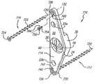
- FIG. 1is a perspective side view of a segment of the spinal column having two spinal fusion implants shown partially in hidden line inserted across the disc space between two adjacent vertebrae with each spinal fusion implant having a spinal fixation device of the present invention shown partially in hidden line secured thereto, spanning across the disc space and inserted into the vertebrae.
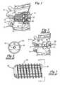
- FIG. 2is a perspective side view of a segment of the spinal column having two spinal fusion implants inserted across the disc space between two adjacent vertebrae.
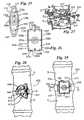
- FIG. 3is an elevational side view of a cylindrical threaded spinal fusion implant.
- FIG. 4is an end view of the cylindrical threaded spinal fusion implant along lines 4 — 4 of FIG. 3 .
- FIG. 5is a perspective side view of a segment of the spinal column having two non-threaded spinal fusion implants with external ratchetings, shown in hidden line, inserted across the disc space between two adjacent vertebrae with each spinal fusion implant having a spinal fixation device of the present invention, shown partially in hidden line, coupled thereto, spanning across the disc space and inserted into the vertebrae.
- FIG. 6is a perspective side view of a segment of the spinal column having two spinal fusion implants having truncated sides with external ratchetings shown in hidden line inserted across the disc space between two adjacent vertebrae with each spinal fusion implant having a spinal fixation device of the present invention shown partially in hidden line coupled thereto, spanning across the disc space and inserted into the vertebrae.
- FIG. 7is a perspective side view of a segment of the spinal column having two spinal fusion implants having a knurled external surface shown in hidden line inserted across the disc space between two adjacent vertebrae with each spinal fusion implant having a spinal fixation device of the present invention shown partially in hidden line coupled thereto, spanning across the disc space and inserted into the vertebrae.
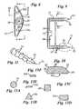
- FIG. 8is a top plan view of the spinal fixation device of the present invention.
- FIG. 9is a side view of the spinal fixation device of the present invention along lines 9 — 9 of FIG. 8 .
- FIG. 10is a cross sectional view taken along lines 10 — 10 of FIG. 8 showing the top member of the spinal fixation device of the present invention.
- FIG. 11is an enlarged fragmentary perspective side view of a projection of the spinal fixation device of the present invention taken along line 11 of FIG. 9 .
- FIG. 12is a cross sectional view of the spinal fixation device of the present invention inserted into the vertebrae and secured to the spinal fusion implant with the arrows showing the forces exerted, the rotational axis and the longitudinal axis of the spinal fusion implant.
- FIG. 13Ais a cross sectional view along line 13 — 13 of FIG. 9 of the preferred embodiment of the projections of the present invention.
- FIGS. 13B, 13 C, 13 D, 13 E, and 13 Fare cross sectional views taken along line 13 — 13 of FIG. 9 showing alternative embodiments of the projections of the spinal fixation device of the present invention.
- FIG. 14is an enlarged elevational side view of the locking screw used to secure the spinal fixation device of the present invention to a spinal fusion implant.
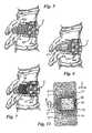
- FIG. 15Ais a cross sectional view of a securing means for locking the locking screw of the present invention.
- FIG. 15Bis a cross sectional view of a first alternative embodiment of the securing means for locking the locking screw of the present invention.
- FIG. 15Cis a cross sectional view of a second alternative embodiment of the securing means for locking the locking screw of the present invention.
- FIG. 16Ais a perspective side view of the instrumentation used for driving the spinal fixation device of the present invention into the vertebrae.
- FIG. 16Bis a perspective side view of a first alternative embodiment of the instrumentation used for driving the spinal fixation device of the present invention into the vertebrae.
- FIG. 17Ais a perspective side view of an alignment rod used to align the spinal fixation device of the present invention.
- FIG. 17Bis a perspective side view of an alternative embodiment of the alignment rod having splines used to align the spinal fixation device of the present invention.
- FIG. 18is a front perspective view of the drill template instrument.
- FIG. 19is a perspective side view of the alignment rod attached to a spinal fusion implant inserted in the disc space between two adjacent vertebrae.
- FIG. 20illustrates the step of drilling guide holes in the vertebrae adjacent to the spinal fusion implant with the drill template instrument of FIG. 18 .
- FIG. 21illustrates a step of the method of inserting the spinal fixation device of the present invention with the alignment rod attached to the spinal fusion implant and the spinal fixation device placed on the driver instrumentation.
- FIG. 22illustrates a step of the short method of inserting the spinal fixation device of the present invention with the driver instrument engaging the splined alignment rod and a hammer for applying an impaction force and driving the driver instrument.
- FIG. 22Ais an enlarged fragmentary view of a projection being inserted into an insertion hole drilled within a vertebra shown in cross section taken along line 22 A of FIG. 21 .
- FIG. 23illustrates another step of the method of inserting the spinal fixation device of the present invention in which the spinal fixation device has been driven into the vertebrae and the driver instrumentation has been removed.
- FIG. 24illustrates another step of the method of inserting the spinal fixation device of the present invention with the splined alignment rod being removed from the spinal fusion implant and the locking screw being inserted and secured the spinal fixation device to the spinal fusion implant.
- FIG. 25is a top plan view of a first alternative embodiment of the spinal fixation device of the present invention.
- FIG. 26is a top plan view of a second alternative embodiment of the spinal fixation device of the present invention.
- FIG. 27is a perspective side view of a third alternative embodiment of the spinal fixation device of the present invention coupled to two spinal fusion implants and inserted in adjacent vertebrae of the spinal column.
- FIG. 28is a top plan view of a fourth alternative embodiment of the spinal fixation device of the present invention inserted into the vertebrae of the spinal column having a spinal fusion implant inserted in the disc space.
- FIG. 29is a top plan view of a fifth alternative embodiment of the spinal fixation device of the present invention inserted into the vertebrae of the spinal column having a spinal fusion implant inserted in the disc space.
- FIG. 30is a perspective bottom view of the fourth alternative embodiment of the spinal fixation device of the present invention.
- FIG. 31is a cross sectional view along lines 31 — 31 of FIG. 29 showing the fifth alternative embodiment of the spinal fixation device of the present invention inserted into the adjacent vertebrae and coupled to a spinal fusion implant.
- FIG. 32is a cross sectional view along lines 32 — 32 of FIG. 29 showing the projections of the fifth alternative embodiment of the present invention with respect to a spinal fusion implant inserted within the disc space.
- FIG. 33is a cross sectional view of a spinal fixation device of the present invention engaging two adjacent vertebrae and being attached to a spinal fusion implant, shown being used as an anchor for a multi-segmental spinal alignment means.
- FIG. 34is an enlarged elevational side view of a threaded post used to connect the spinal fixation device of the present invention to a multi-segmental spinal alignment means.
- FIG. 35is an exploded perspective view of a sixth alternative embodiment of the spinal fixation device of the present invention having independent projection members that are screws.
- FIGS. 1 and 2two identical spinal fixation devices of the present invention, each being generally referred to by the numerals 10 and 11 , respectively, are shown inserted into two vertebrae V adjacent to a disc D of a segment of the human spine.
- Each spinal fixation device 10 and 11is shown coupled to identical spinal fusion implants 40 and 41 that have been surgically implanted in the disc space between adjacent vertebrae V.
- the spinal fixation devices 10 and 11stabilize a segment of the spine, prevent the dislodgement of the spinal fusion implant 40 , and remain permanently fixated to the spine once applied.
- the spinal fixation devices 10 and 11are identical such that the description of one is equally applicable to the other. Thus, the description that follows will be directed to spinal fixation device 10 .
- the spinal fusion implant 40such as, but not limited to, the spinal fusion implant described by Michelson, U.S. Pat. No. 5,015,247 issued on May 14, 1991, is shown.
- the spinal fusion implant 40is cylindrical in shape and has external threads 42 at its outer perimeter for engaging the bone of the vertebrae V adjacent to the disc D.
- the spinal fusion implant 40has an insertion end 43 having a depression 44 and a threaded aperture 45 for engaging a portion of the spinal fixation device 10 and also for engaging a portion of an instrument used to insert the spinal fixation device 10 into the vertebrae V.
- the spinal fixation devices 10 and 11 of the present inventionare not limited in use with a threaded spinal fusion implant 40 and 41 , but may be used with different types of spinal fusion implants.
- the spinal fixation devices 10 and 11may be coupled to spinal fusion implants 40 a and 41 a , respectively, each having external ratchetings 42 a instead of external threads 42 as shown in FIG. 5 .
- the spinal fixation devices 10 and 11may be coupled to spinal fusion implants 40 b and 41 b , respectively, each having a partially cylindrical shape with at least one truncated side 47 as shown in FIG. 6 .
- the spinal fixation devices 10 and 11may be coupled to spinal fusion implants 40 c and 41 c , respectively, each having a knurled external surface 48 as shown in FIG. 7 . It is also appreciated that the spinal fixation devices may be used with a variety of other bone fusion implants without departing from the scope of the present invention.
- the spinal fixation device 10 of the present inventioncomprises a staple member 12 having a substantially planar top member 14 which is of sufficient length to span one intervertebral disc D and to engage, via a plurality of essentially perpendicular extending projections 16 and 17 , the vertebrae V adjacent to that disc D.
- the top member 14has a central opening 18 within a concentric, countersunk recess 19 for receiving therethrough a screw or similar coupling means for coupling the spinal fixation device 10 to the spinal fusion implant 40 .
- the top member 14has an upper surface 20 having a pair of openings 22 a and 22 b for receiving the posts 88 a and 88 b of a driving instrument 80 which is described in greater detail below in reference to FIGS. 16A and 16B.
- the top member 14is generally triangularly shaped and is radiused along curved side 24 and straight side 26 .
- the curved side 24 of the top member 14is radiused at its upper edge 25 and at the upper edge 27 of straight side 26 to conform to the external curvature of the vertebrae V.
- smooth surfacesare created at the upper edges 25 and 27 of the top member 14 that are contoured to the shape of the external curvature of the vertebrae V when the staple member 12 is in place.
- the smooth contoured surface of the upper edges 25 and 27 of the top member 14prevent aortic erosions and perforations of the vessels proximate the vertebral column such as the vena cava and the iliac vessels which might otherwise result from friction.
- the top member 14has a width ranging from 6.0 mm to 28.0 mm, with 10.0 mm being the preferred width, and having a thickness in the range of 2.0 mm to 4.0 mm, with 3.0 mm being the preferred thickness.
- the staple member 12is made of material appropriate for human surgical implantation including all surgically appropriate metals such as but not limited to, titanium, titanium alloy, chrome molybidium alloys, stainless steel; or non-metallic materials including permanent or resorbable substances or composites, carbon fiber materials, resins, plastics, ceramics or others.
- the staple member 12 of the present inventionmay be treated with, or even composed of, materials known to participate in or promote in the fusion process or bone growth.
- the spinal fixation device 10may be coated with materials to promote bone fusion and thus promote the incorporation and ultimate entombment of the spinal fixation device 10 into the bone fusion mass.
- a bone fusion promoting materialsuch as, but not limited to hydroxyapatite, hydroxyapatite tricalcium phosphate or bone morphogenic protein, results in a speedier vertebra V to vertebra V fusion as bone may grow along the coated spinal fixation device 10 bridging the two vertebrae V so that the spinal fixation device 10 acts as a trellis and supplies essential chemical elements to facilitate the bone fusion process.
- the projections 16 and 17are positioned at opposite ends of the top member 14 and depend downwardly and extend perpendicularly from the bottom surface 30 of the top member 14 .
- the projections 16 and 17each terminate in a distal end 32 that is pointed and sharpened to facilitate the insertion of the projections 16 and 17 into the vertebrae V.
- the staple member 12is most effective when the interprojection distance I between projections 16 and 17 is at least 4.0 mm and preferably 6.0 mm greater than the diameter of the particular spinal fusion implant 40 for which the spinal fixation device 10 is being used so that at least 2.0 mm and preferably 3.0 mm of bone from the vertebrae V will be present between the spinal fusion implant 40 and each of the projections 16 and 17 .
- intervertebral spinal fusion implantshave a diameter that ranges from 12.0 mm to 28.0 mm, therefore, the interprojection distance I typically will range from 18.0 mm to 34.0 mm for most applications.
- the projections 16 and 17comprise a series of segmented and ratcheted portions 34 .
- the segmented and ratcheted portions 34provide for a “one way” insertion of the staple member 12 to prevent the backing-out of the projections 16 and 17 once they are inserted into the bone of the vertebrae V.
- each segmented and ratcheted portion 34 of the projections 16 and 17is conical in shape and the diameter of each segmented and ratcheted portion 34 increases in the direction from the distal end 32 toward the top member 14 so that the projections 16 and 17 resemble a stack of cones.
- the segmented and ratcheted portions 34are spaced approximately 2.0 mm to 4.0 mm apart, with 3.0 mm being the preferred distance between each segmented and ratcheted portion 34 .
- each projection 16in order to further facilitate the insertion of the projections 16 and 17 into the vertebrae V, the distal end 32 of each projection 16 has an eccentric, incline-planed inner surface 36 as shown in FIG. 11 .
- the eccentric, incline-planed inner'surface 36 of each of the projections 16 and 17create a force F which pushes the bone of the vertebrae V toward the spinal fusion implant 40 as the staple member 12 is inserted into each of the vertebrae V as shown in FIG. 12 .
- the projections 16 and 17are cylindrical in shape having a circular cross section as shown for projection 16 in FIG. 13 A.
- the projection 16 amay have a triangular cross section as shown in FIG. 13B; the projection 16 b may have a square cross section as shown in FIG. 13C; the projection 16 c may have a rectangular cross section as shown in FIG. 13D; the projection 16 d may have a trapezoidal cross section as shown in FIG. 13E; or the projection 16 e may have a cross section with a configuration as shown in FIG. 13 F.
- the projections 16 and 17each have a diameter of approximately 2.0 mm to 4.0 mm, with 3.0 mm being the preferred diameter at the widest point.
- the projection 16 and 17each have a length ranging from 16.0 mm to 28.0 mm, with 22.0 mm being the preferred length when the spinal fixation device 10 is implanted in the direction of the anterior aspect of the vertebra V to the posterior aspect of the vertebrae V.
- the projections 16 and 17each could have a longer length depending on the diameter of the vertebrae V in which the projections 16 and 17 are implanted.
- the top member 14 of the staple member 12has a central bar 35 extending from the center of its bottom surface 30 , for interdigitating and mating to an already implanted intervertebral spinal fusion implant 40 .
- the central bar 35has a thickness in the range of 0.5 mm to 1.5 mm, with 0.5 mm being the preferred thickness.
- the central bar 35is configured so that it complements and engages the depression 44 at the insertion end 43 of the spinal fusion implant 40 . Once engaged to the depression 44 , the bar 35 interdigitates with the depression 44 of the spinal fusion implant 40 to lock and prevent the rotation of the spinal fusion implant 40 .
- the staple member 12is secured to the spinal fusion implant 40 by a screw 60 having threaded end 61 with a locking thread pattern 62 and screw head 64 .
- the locking thread pattern 62has a reduced pitch at the bottom of the threaded end 61 such that the screw 60 is self-locking.
- the threaded pattern 62may be any of the means for locking a screw well known by those skilled in the art.
- the threaded end 61 of the screw 60passes through the central opening 18 of the top member 14 and the threaded pattern 62 threads into the threaded aperture 45 of the spinal fusion implant 40 .
- the screw head 64fits within the countersunk recess 19 of the top member 14 such that the screw head 64 is at or below the plane of the upper surface 20 of the top member 14 .
- the central opening 18has a diameter ranging from 4.5 mm to 5.5 mm, with 5.0 mm being the preferred diameter.
- the countersunk recess 19has a diameter in the range of 6.0 mm to 8.0 mm with 7.0 mm being the preferred diameter.
- FIGS. 15A, 15 B, and 15 Can enlarged cross sectional view of three different embodiments of a securing means 65 for locking the screw 60 once it is threaded to the spinal fusion implant 40 are shown.
- the securing means 65comprises a notch 66 in the surface 20 of the top member 14 which is preferably made of metal.
- a chisel Cis used to bend a portion 67 of the top member 14 into the central opening 18 and against the screw head 64 so as to prevent the outward excursion and any unwanted loosening of the screw 60 .
- FIG. 15Ba second embodiment of the securing means 65 a is shown comprising a central score 66 a concentric with the central opening 18 .
- a screw 60 a having a slot 61 a in the screw head 64 ais threaded and securely tightened to the spinal fusion implant 40 .
- An instrument Tis partially inserted into slot 61 a after which an impaction force F i is applied to the instrument T to spread apart the screw head 64 a in the direction of the arrows A so that the screw head 64 a becomes deformed from the impaction force F i and fits within the central score 66 a .
- the outward excursion of the screw 60 ais prevented by the top lip 68 of the central score 66 a.
- a third embodiment of the securing means 65 bcomprising a screw 60 b having a screw head 64 b with a slightly flanged portion 69 b near the top and a slot 61 b .
- the central opening 18has along its circumference a recess 66 b for receiving the flanged portion 69 b of the screw head 64 b .
- the securing means 65 brelies on the natural resiliency of the metal screw head 64 b such that when the screw 60 b is being driven by a screw driver, the screw head 64 b flexes in the direction of the arrows B.
- the flanged portion 69 b of the screw head 64 bslides along the interior of the central opening 18 so that the screw head 64 b is below the top lip 68 b of the recess 66 b .
- the screw head 64 breturns to its natural state in the direction opposite to the arrows B so that the flanged portion 69 b is within the recess 66 b .
- the outward excursion of the screw 60is thus prevented by the top lip 68 b which blocks the screw head 64 b by catching the flanged portion 69 b.
- FIGS. 16A-18show the instrumentation used for installing the spinal fixation device 10 .
- a driving instrument 80 used for inserting the spinal fixation device 10 into the vertebrae Vis shown having a hollow tubular shaft 82 which terminates at one end to a bottom flat member 84 and terminates to a top flat member 86 at the other end.
- the bottom flat member 84is preferably configured so that it conforms to the shape of the top member 14 of the staple member 12 .
- the driving instrument 80has a pair of short posts 88 a and 88 b extending from the bottom flat member 84 .
- the posts 88 a and 88 bare oriented on the bottom flat member 84 so as to correspond to the position of the openings 22 a and 22 b in the upper surface 20 of the top member 14 of the staple member 12 .
- Each of the posts 88 a and 88 bfit into each of the openings 22 a and 22 b and keep the staple member 12 aligned on the bottom flat member 84 of the driving instrument 80 .
- the openings 22 a and 22 b in the top member 14may be depressions within the surface 20 of the top member 14 or may be holes that pass through the top member 14 .
- the openings 22 a and 22 bgave a diameter ranging from 1.5 mm to 3.5 mm, with 2.5 mm being the preferred diameter.
- FIG. 16Ban alternative embodiment of the driving instrument 80 ′ which is, used for inserting into the vertebrae V the spinal fixation device 210 , described in detail below in reference to FIG. 26, is shown having a hollow tubular shaft 82 ′ which terminates at one end to a bottom flat member 84 ′ and terminates to a top flat member 86 ′ at the other end.
- the bottom flat member 84 ′is rectangular in shape so that it conforms to the shape of the top member 214 of the spinal fixation device 210 .
- the driving instrument 80 ′has a pair of short posts 88 ′ a , 88 ′ b , 88 ′ c and 88 ′ d extending from the bottom flat member 84 ′.
- the posts 88 ′ a - 88 ′ dare oriented on the bottom flat member 84 ′ so as to correspond to the position of the openings 222 a - 222 d of the spinal fixation device 210 .
- Each of the and keep the spinal fixation device 210aligned on the bottom flat member 84 ′ of the driving instrument 80 ′.
- an alignment rod 70comprising a cylindrical shaft 72 having a smooth exterior surface 73 and a threaded end 74 may, be threadably attached to the threaded aperture 45 of the spinal fusion implant 40 is shown.
- the alignment rod 70fits through the central opening 18 of the spinal fixation device 10 and is used to properly align the projections 16 and 17 on each side of the spinal fusion implant 40 prior to engaging the vertebrae V. Further, the alignment rod 70 also serves as a guide post for the drilling template instrument 50 described in greater detail below.
- a splined alignment rod 70 ′that has a finely splined surface 72 ′ along its longitudinal axis and a threaded end 74 ′ that may be attached to the threaded aperture 45 of the spinal fusion implant is shown.
- a drilling template instrument 50for creating a pair of insertion holes 53 a and 53 b in each of the vertebrae V for receiving each of the projection 16 and 17 respectively is shown.
- the drilling template instrument 50has a template 52 with a central aperture 54 therethrough and guide passages 55 and 56 for guiding a drill bit 51 of a drilling tool.
- Attached to the template 52is a handle 58 which angles away from the template 52 so as not to obstruct the line of sight of the surgeon and to allow easy access to the template 52 and easy access to the guide holes 55 and 56 for the drill bit 51 .
- a central member 59(similar in structure and function to the central bar 35 ) for mating to an already implanted intervertebral spinal fusion implant 40 .
- the central member 59interdigitates with the depression 42 of the spinal fusion implant 40 so that the template 52 is properly oriented about the spinal fusion implant 40 and the guide holes 55 and 56 are properly oriented with respect to the vertebrae V adjacent to the spinal fusion implant 40 .
- the alignment rod 70serves as a guide post for the drill template instrument 50 as it fits through the central aperture 54 of the template 52 and aligns the template 52 with respect to the spinal fusion implant 40 and insures that it is coaxial.
- the central aperture 54 of the drilling template instrument 50is smooth so that if it is placed over a splined alignment rod 70 ′ the drilling template instrument 50 may be easily rotated about the splined alignment rod 70 ′ into position'such that the central member 59 is able to mate and interdigitate with the depression 44 of the spinal fusion implant 40 .
- the spinal fixation device 10 of the present inventionis inserted in the following manner: At least one spinal fusion implant 40 is surgically implanted so that it is substantially within the disc space between two adjacent vertebrae V and engages at least a portion, of each of the two adjacent vertebrae V. Once the spinal fusion implant 40 is in place, the alignment rod 70 is attached to the threaded aperture 45 of the spinal fusion implant 40 .
- the alignment rod 70serves as a guide post for the drilling template instrument 50 as it fits through the central aperture 54 of the template 52 and aligns the template 52 coaxially with respect to the spinal fusion implant 40 .
- the insertion holes 53 a and 53 bare drilled in each of the adjacent vertebrae V with a drilling instrument having a drill bit, 51 with a diameter that is substantially smaller than the diameter of each the projections 16 and 17 of the staple member 12 .
- the drill template instrument 50is removed from the spinal fusion implant 40 and from the alignment rod 70 .
- the alignment rod 70is left in place attached to the threaded aperture 45 of the spinal fusion implant 40 .
- the staple member 12is placed onto the driving instrument 80 used for driving and fixing the staple member 12 into the vertebrae V so that the bottom flat member 84 and the posts 88 a and 88 b are aligned with the top member 14 and the depressions 22 a and 22 b of the top member 14 .
- the alignment rod 70serves as a guide post for the staple member 12 as it fits through the central opening 18 of the staple member 12 and aligns the staple member 12 coaxially with respect to the spinal fusion implant 40 .
- the staple member 12 and the driving instrument 80are aligned with respect to the alignment rod 70 so that the alignment rod 70 passes through the central opening 18 of the staple member 12 and is inserted into the central hollow portion 89 of the driving instrument 80 .
- the staple member 12 and the driving instrument 80are then lowered along the alignment rod 70 so that the sharp distal end 32 of each of the projections 16 and 17 comes into contact with the external surface of the vertebrae V and is aligned with the previously drilled insertion holes 53 a and 53 b.
- the insertion holes 53 a and 53 bbe drilled so that when the projections 16 and 17 are inserted into the holes 53 a and 53 b , the incline planed inner surface 36 of each of the projections 16 and 17 contacts the inner wall W of the insertion holes 53 a and 53 b that is closest to the spinal fusion implant 40 .
- a compression force Fis created as each of the projections 16 and 17 of the staple member 12 is inserted into insertion holes 53 a and 53 b , respectively, compressing the bone of the vertebrae V toward the spinal fusion implant 40 .
- the staple member 12is then driven into the vertebrae V by applying a high impaction force to the driving instrument 80 with a hammer H or other impacting means against the top flat member 86 of the driving instrument 80 .
- the staple member 12is driven into the vertebrae V such that the projections 16 and 17 are moved forward into the insertion holes 53 a and 53 b , respectively, until the bottom surface 30 of the top member 14 of the staple member 12 comes to rest against the surface of the vertebrae V.
- the driving instrument 80is lifted away from the alignment rod 70 so that the alignment rod 70 is no longer within the central hollow portion 89 of the driving instrument 80 .
- the alignment rod 70is unthreaded from the threaded aperture 45 and is removed from the spinal fusion implant 40 .
- the staple member 12is secured to the spinal fusion implant 40 with the locking screw 60 which has a threaded pattern 62 with a reduced pitch.
- the reduced pitch of the locking screw 60locks the locking screw 60 to the spinal fusion implant 40 with minimal turning of the locking screw 60 and prevents any unwanted loosening.
- any of the three embodiments of the securing means 65 , 65 a or 65 b described above in reference to FIGS. 15A-15Cmay be used to further prevent any unwanted loosening and outward excursion of the screw 60 .
- the spinal fusion implant 40is prevented from rotating along its rotational axis R by its connection to the staple member 12 which is fixated across the disc space between the vertebrae V.
- the staple member 12is prevented from backing out from the vertebrae V along the longitudinal axis L by its connection to the spinal fusion implant 40 and by the segmented and ratcheted portions 34 of the projections 16 and 17 .
- the staple member 12 and the spinal fusion implant 40interact to prevent the dislodgement of each other from the vertebrae V in which they are implanted.
- the staple member 12is made safe against dislodgement by attachment to the spinal fusion implant 40 and the stability of the spinal fusion implant 40 is assured as it is also stabilized by the staple member 12 and each works in connection with the other to remove the only remaining degree of freedom that would allow for the disengagement of either.
- the incline plan ed inner surface 36 at the distal end 32 of the projections 16 and 17forces bone toward the spinal fusion implant 40 along force lines F to further secure the spinal fusion implant 40 and further prevent the dislodgement of the spinal fusion implant 40 .
- Short Methoda shorter method (hereinafter referred to as the “Short Method”) of inserting the spinal fixation device 10 is possible by omitting the steps of drilling the insertion holes 53 a and 53 b prior to inserting the staple member 12 into the vertebrae V.
- the splined alignment rod 70 ′that is finely splined along its longitudinal axis is used instead of the alignment rod 70 .
- the staple member 12may be placed over the splined alignment rod 70 ′ so that the splined alignment rod 70 ′ passes through the aperture 18 and into the central aperture 89 of the driving instrument 80 .
- the central aperture 89 of the driving instrument 80is correspondingly splined to the splines of the splined alignment rod 70 ′ so that the staple member 12 can be aligned with respect to the spinal implant 40 .
- the alignment of the staple member 12 and the driving instrument 80is maintained as the corresponding splines of the central aperture 89 interdigitate with the splines of the splined alignment rod 70 ′ and prevent the rotation of the staple member 12 about the splined alignment rod 70 ′.
- the prevention of rotation about the splined alignment rod 70 ′is especially important when the Short Method is used to insert the spinal fixation device 10 , as no insertion holes 53 a and 53 b have been drilled in the vertebrae V.
- the staple 12can be driven directly into the vertebrae V by the application of a high impaction force to the driving instrument 80 as described above and shown in FIG. 22 .
- the Short Method of inserting the staple member 12reduces the amount of time, required to insert and secure the spinal fixation device 10 of the present invention and thus reduces the overall duration of the spinal fixation surgical procedure.
- a first alternative embodiment of a spinal fixation device 110 having a staple member 112 with a top member 114 generally in the shape of an elongated oval having two curved sides 124 a and 124 bis shown.
- the curved sides 124 a and 124 bhave upper edges 125 a and 125 b , respectively, that are radiused to conform to the external curvature of the vertebrae V thereby creating smooth contoured surfaces as described above for the spinal fixation device 10 , the preferred embodiment of the present invention.
- the top member 114has openings 122 a and 122 b in the upper surface 120 of the top member 114 and has two projections 116 and 117 depending downwardly from the bottom surface 130 of the top member 114 at opposite ends of the staple member 112 .
- the projections 116 and 117are the same as the projections 16 described above for the preferred embodiment.
- a second alternative embodiment of the spinal fixation device 210 having a staple member 212is shown with a top member 214 that is generally rectangular in shape and has an upper surface 220 with openings 222 a , 222 b , 222 c , and 222 d .
- the top member 214has four projections 216 , 217 , 218 , and 219 depending from its bottom surface at each of its corners.
- the projections 216 - 217are the same as the projections 16 and 17 described above in the preferred embodiment.
- the top member 214has four straight sides 228 a , 228 b , 228 c , and 228 d having upper edges 225 a , 225 b , 225 c , and 225 d , respectively, that are radiused to conform to the to external curvature of the vertebrae V create a smooth surface as described above for the preferred embodiment.
- the driving instrument 80 ′ shown in FIG. 16Bis used to insert the spinal fixation device 210 .
- a third alternative embodiment of the spinal fixation device 310 having a staple 312 with a top member 314 that is generally triangularis shown.
- the top member 314has two projections 316 and 317 depending from the bottom surface of the top member 314 that engage the vertebrae V.
- Extending from the center of the bottom surface of the top member 314is a central member 390 which is similar to the central bar 35 of the preferred embodiment of the spinal fixation device 10 in that the central member 390 interdigitates with the depression 44 a of the spinal fusion implant 40 .
- the central bar 390also has an extension arm 392 that extends laterally from the top member 314 to span the diameter of an adjacent spinal fusion implant 41 .
- the extension arm 392interdigitates with the depression 44 of the spinal implant 41 .
- the extension arm 392has a central aperture 374 for receiving a screw 60 b used to couple the extension arm 392 to the spinal fusion implant 41 .
- a single spinal fixation device 310is capable of interdigitate with two adjacent spinal fusion implants 40 and 41 to lock and prevent the rotation and any excursion of the spinal fusion implants 40 and 41 .
- the fixation of two spinal fusion implants 40 and 41is possible while leaving no protruding metal, such as the top member 314 , on the side of the spine where the vessels are located in close approximation to the vertebrae as is the case with the L 4 and L 5 vertebrae where the vessels are located over the left side of those vertebrae.
- any of the securing means 65 - 65 bdescribed above may be used to lock the screw 60 b to the extension arm 392 .
- a fourth alternative embodiment of the spinal fixation device 410 having a staple member 412 with a top member 414 that is generally triangular in shapeis shown in the installed position.
- the top member 414is wider and larger than top member 14 as it is used with an implant 440 having a large diameter in the range of 22.0 mm to 28.0 mm.
- the top member 414needs to be wider when used with implant 440 in order to provide a central bar 435 of sufficient length to interdigitate and mate with the depression 444 of the implant 440 in order to prevent its rotation.
- the top member 414is tapered at portion 416 so as not to cause erosion or pressure against the vessels that may be present in the area of the spine adjacent to the portion 416 of the top member 414 .
- FIGS. 29-32a fifth alternative embodiment of the spinal fixation device 510 with a staple member 512 having a generally rectangular top member 514 is shown.
- the staple member 512is similar in structure to the staple 212 described above except that the top member 514 has multipronged projection blades 516 and 517 depending from its lower surface 530 as shown in FIG. 30 .
- the multipronged projection blades 516 and 517have the same function and similar structure as the projections 16 and 17 described above and include segmented and ratcheted portions 534 which are similar in design are function to segmented and ratcheted portions 34 .
- the multipronged blade projections 516 and 517offer the added advantage of increasing the strength and stability of the staple member 514 once it is inserted into the bone of the vertebrae V providing a greater area of engagement of the staple member 512 to the vertebrae V.
- the lower surface 530has knobs 532 and 534 extending therefrom for engaging and interdigitating with a spinal implant 540 having an insertion end 541 with openings 542 and 544 for receiving knobs 532 and 534 respectively.
- the spinal fusion implant 540is shown inserted within the disc space between two adjacent vertebrae V.
- the spinal implant 540is generally rectangular in shape.
- the multiprong blade projections 516 and 517have a width that is approximately equal or slightly less than the width of the spinal fusion implant 540 .
- the spinal fixation device, 510compresses the bone of the vertebrae V towards the spinal fusion implant 540 as discussed above in reference to FIG. 12 .
- the spinal fixation device 510may be secured to the spinal fusion implant 540 with a screw 60 as discussed above.
- the spinal fixation device 510 having a staple member 512is the preferred embodiment of the present invention for use with a multi-segmental spinal alignment means 600 described in greater detail below in that the staple 512 provides a more solid anchoring means that can resist greater torsion forces resulting from the application of the multi-segmental spinal alignment means 600 to align the spine.
- the spinal fixation device 10 of the present inventioncould be made of resorbable materials, such as bio-compatible resorbable plastics, that resorb at an appropriate rate such that once the spinal fixation device 10 is no longer needed (i.e. when spinal fusion is complete) the body would resorb the spinal fixation device 10 .
- resorbable materialis polygalactone, however any other resorbable plastic or other material safely usable within the human body are also within the scope of the present invention.
- the spinal fixation devicecould be only in part resorbable such that the projections 16 and 17 of the staple member 12 would be non-resorbable and would remain incarcerated in the vertebrae V and sealed of f once the resorbable portion of the staple is resorbed by the body.
- the spinal fixation device 510 of the present inventionmay be used as an anchor for a multi-segmental spinal alignment means 600 , such that a multiplicity of spinal fixation devices may then be interconnected via a cable, rod, bar, or plate, so as to achieve or maintain any desired multi-segment spinal alignment.
- the multi-segmental spinal alignment means 600comprises more than one spinal fixation device 510 of the present invention placed in series along the spine such that each spinal fixation device 510 spans one disc D and engages two adjacent vertebrae V.
- the spinal fixation device 510is preferred over the other embodiments of the present invention in that it has a greater area of engagement with the vertebrae V so as to provide a solid anchoring means for the multi-segmental spinal alignment means 600 .
- other embodimentsincluding but not limited to those described herein may be utilized as anchoring means for the multi-segmental spinal alignment means 600 .
- each spinal fixation device 510interdigitates with and is connected to a spinal fusion implant 610 having an insertion end 612 , an interior chamber 614 and is inserted in the disc space between the two adjacent vertebrae.
- the spinal fusion implant 610has a threaded blind hole 620 for receiving a threaded post 622 therein.
- the blind hole 620has a casing that is made of strong surgically, implantable material such as, but not limited to titanium.
- the casing 624extends from the insertion end 612 of the spinal fusion implant 610 into the interior central chamber 614 .
- the insertion end 612has a rigid construction that is capable of withstanding high torsion forces resulting from the tensioning of the multi-segmental spinal alignment means to align segments of the spine.
- the insertion end 612 of the spinal fusion implanthas an end portion 626 that closes the insertion end 612 .
- the end portionis substantially thicker than the rest of the spinal fusion implant 610 and in the preferred embodiment, the end portion 626 has thickness ranging from 1.5 mm to 4.0 mm, with 2.5 mm being the preferred thickness.
- the threaded post 622has a threaded end 628 with a locking thread pattern that is substantially longer than the locking thread pattern 62 of the screw 60 described above and a head portion 630 having a hole 632 for receiving a rod 634 or a cable therethrough.
- the head portion 630has a rounded exterior surface to prevent any damage such as aortic erosion to the vessels in the area adjacent to the spine.
- the threaded posthas a diameter ranging from 3.0 mm to 6.0 mm, with 4.5 mm being the preferred diameter and has a length ranging from 15.0 mm to 25.0 mm, with 20.0 mm being the preferred length
- the head portion 630extends at a height above the top member 514 of the spinal fixation device 510 of approximately 8.0 mm to 16.0 mm, with 12.0 being the height preferred once it is threadably attached the spinal fusion implant 610 such that it does not significantly protrude from the spinal column into the tissue and vessels adjacent thereto.
- each threaded post 622is attached to the spinal fusion implant 610 , the head portion 630 of each threaded post 622 are connected to one another by the rod 634 having a sufficient diameter to fit through the hole 632 of each head portion 630 .
- the rod 634has at least a portion thereof that is threaded so that a plurality of lock nuts 638 may be used to secure the rod 634 to the head portions 630 .
- the lock nuts 638may also be used as length adjusting means to adjust the length of the rod 634 between head portions 630 so that segmental portions of the spine may be held closer together or held further aport for the purposes of aligning the spine.
- a plurality of multi-segmental spinal alignment means 600may be placed in series either on one side or on opposite sides of the spine, such that one side of the spine may be extended while the other side may be held stationary or may be compressed in order to achieve proper spinal alignment.
- the multi-segment spinal alignmentmay be maintained by keeping the rod tensioned with the lock nuts 638 or by any other means well known by those skilled in the art.
- a cable, a plate or any other means well known by those skilled in the artmay be used to interconnect the multi-segmental spinal alignment means.
- the spinal fixation device 710comprises a top member 714 that is similar to the top member 14 described above, except that it does not have projections 16 and 17 extending from the bottom surface. Like numbers are being used to designate identical features of the top members 14 and 714 .
- top member 714instead of having projections 16 and 17 , independent projection members 716 and 717 in the form of screws are used to secure the top member 714 of the spinal fixation device 710 to the vertebrae V of the spine.
- the projection screw members 716 and 717each terminate in a sharp distal end 720 and 722 respectively, have a threaded portion 723 , and have screw heads 724 and 726 for engaging a screw driver or similar driving instrument.
- the top member 714has a hole 728 on one end and a hole 730 at its other end through which each of the projection screw members 716 and 717 respectively, may pass.
- the projections screw members 716 and 717pass through the holes 728 and 730 to engage the vertebrae V.
- Each of the holes 728 and 730has a concentric counter sunk recess 732 for receiving and seating the screw heads 724 and 726 of the projection screw members 716 and 717 so that the screw heads 724 and 726 are flush or below the top surface 20 of the top member 714 once inserted into the vertebrae V.
- the projection screw members 716 and 717can be rotationally advanced into the vertebrae instead of by way of an impaction force such that the potential for damage to the vertebrae V is reduced.
- the threads of the threaded portion 723follow one another as the projection screw members 716 and 717 are being screwed into the bone such that the integrity of the vertebrae V is preserved.
- the penetration depth of the spinal fixation device 710 into the bone of the vertebrae Vmay be easily altered by selecting different sized projection screw members 716 and 717 appropriate for the particular vertebrae being fused. Further, it is possible to configure the holes 728 and 730 in the top member 714 such that the projection screw members 716 and 717 may be inserted into the vertebrae V from a number of different angles relative to the top member 714 .
- Adjacent and proximate to each of the holes 728 and 730are threaded openings 740 and 742 , respectively, for receiving locking screws 744 and 746 respectively.
- Each of the locking screws 744 and 746have a head portion 750 and a locking thread portion 754 for threadably and lockably engaging the threaded openings 740 and 742 .
- the locking screws 744 and 746are attached to the top member 714 after the projection screw members 716 and 717 have been inserted into the vertebrae V. At least a part of the head portion 750 and 752 blocks and preferably makes contact with the screw projections 716 and 717 to prevents any unwanted loosening and outward excursion of the screw projections 716 and 717 .
- the projection members 716 and 717instead of being threaded screws, many have a number of other configurations such as, but not limited to, the configurations of the projections described above for the various embodiments of the present invention. If the projections members 716 and 717 are ratcheted instead of being threaded, they can be driven into the vertebrae V with a driving instrument and impaction force as described above for the method of the present invention.
Landscapes
- Health & Medical Sciences (AREA)
- Engineering & Computer Science (AREA)
- Biomedical Technology (AREA)
- Life Sciences & Earth Sciences (AREA)
- Orthopedic Medicine & Surgery (AREA)
- Surgery (AREA)
- Animal Behavior & Ethology (AREA)
- Veterinary Medicine (AREA)
- Public Health (AREA)
- Heart & Thoracic Surgery (AREA)
- General Health & Medical Sciences (AREA)
- Nuclear Medicine, Radiotherapy & Molecular Imaging (AREA)
- Neurology (AREA)
- Medical Informatics (AREA)
- Molecular Biology (AREA)
- Oral & Maxillofacial Surgery (AREA)
- Vascular Medicine (AREA)
- Transplantation (AREA)
- Cardiology (AREA)
- Rheumatology (AREA)
- Dentistry (AREA)
- Prostheses (AREA)
- Surgical Instruments (AREA)
Abstract
Description
This application is a continuation of prior application Ser. No. 09/126,585, filed Jul. 31, 1998, now U.S. Pat. No. 6,136,001, which is a continuation of application Ser. No. 08/926,334, filed Sep. 5, 1997, now U.S. Pat. No. 6,120,503 which is a continuation of application Ser. No. 08/589,787, filed Jan. 22, 1996, now abandoned which is a continuation of application Ser. No. 08/219,626, filed Mar. 28, 1994, now abandoned.
1. Field of the Invention
This invention relates to surgical interbody fixation devices and in particular to a surgically implantable device for the stabilization of adjacent vertebrae of the human spine undergoing spinal arthrodesis and for the prevention of the dislodgement of spinal fusion implants used in the fusion process.
2. Description of the Related Art
When a segment of the human spine degenerates, or otherwise becomes diseased, it may become necessary to surgically remove the affected disc of that segment, and to replace it with bone for the purpose of obtaining a spinal fusion by which to restore more normal, pre-morbid, spatial relations, and to provide for enhanced stability across that segment. Performing such surgery of the spine from an anterior (front) approach offers the great advantage of avoiding the spinal cord, dural sac, and nerve roots. Unfortunately, in entering the disc space anteriorly a very important band-like structure called the anterior longitudinal ligament, is violated. This structure physiologically acts as a significant restraint resisting the anterior displacement of the disc itself and acting as a tension band binding the front portions of the vertebrae so as to limit spinal hyperextension.
Historically, various devices have been utilized in an attempt to compensate for the loss of this important stabilizing structure. These devices have assumed the form of blocks, bars, cables, or some combination thereof, and are bound to the vertebrae by screws, staples, boats, or some combination thereof. The earliest teachings are of a metal plate attached to adjacent vertebrae with wood-type screws. Dwyer teaches the use of a staple-screw combination. Brantigan U.S. Pat. No. 4,743,256 issued on May 10, 1988, teaches the use of a block inserted to replace the disc, affixed to a plate then screwed to the vertebrae above and below. Raezian U.S. Pat. No. 4,401,112 issued on Aug. 30, 1993, the use of a turnbuckle affixed to an elongated staple such that at least one entire vertebral body is removed, the turnbuckle portion is placed within the spine, and the staple extends both above and below the turnbuckle and engages the adjacent vertebrae to the one removed.
Unfortunately, both staples and screws have quite predictably demonstrated the propensity to back out from the vertebrae. This is quite understandable as any motion, either micro or macro, tends to stress the interface of the metallic implant to the bone, and in doing so causes the bone to relieve the high stress upon it by resorbing and moving away from the metal. This entropic change is universally from the more tightened and thus well-fixated state, to the less tightened and less fixated state. For a staple, this is specifically from the more compressed and engaged state, to the less compressed and disengaged state. Similarly, screws in such a dynamic system loosen and back out.
The potential consequences of such loosening and consequent backing out of the hardware from the anterior aspect of the vertebral column may easily be catastrophic. Because of the proximity of the great vessels, aortic erosions and perforations of the vena cava and iliac vessels have usually occurred with unfortunate regularity and have usually resulted in death.
Therefore, the need exists for a device which is effective in restoring stability to a segment of the spine such as, but not limited to, the anterior aspect of the human spine and which will without danger remain permanently fixated once applied.
The present invention is directed to a spinal fixation device for stabilizing a segment of the human spine and for preventing the dislodgement of intervertebral spinal fusion implants, which remains permanently fixated to the spine once applied. The spinal fixation device of the present invention comprises a staple member made of a material appropriate for human surgical implantation and which is of sufficient length to span the disc space between two adjacent vertebrae. The staple member engages, via essentially perpendicular extending projections, the vertebrae adjacent to that disc space. The projections are sharpened and pointed so as to facilitate their insertion into the vertebrae and are segmented or ratcheted to prevent the staple member from disengaging and backing out once inserted.
In the preferred embodiment of the spinal fixation device of the present invention, a portion of the staple member interdigitates with an already implanted intervertebral spinal fusion implant and the staple member is bound to the spinal fusion implant by a locking mechanism such as a screw with a locking thread pattern. The anchoring of the staple member via a locking mechanism to a spinal fusion implant protects the patient from the danger of the staple member itself disengaging and backing out. Further, if the spinal fusion implant is externally threaded, such as the spinal fusion implant taught by Michelson, U.S. Pat. No. 5,015,247 issued on May 14, 1991, then the staple member could only back out if the spinal fusion implant were free to rotate. However, the rotation of the spinal fusion implant in this instance is blocked by its connection to the staple member which is fixated across the disc space in such a way as to be incapable of rotation. Thus, the staple member is made safe against dislodgement by attachment to the spinal fusion implant and the stability of the spinal fusion implant is assured as it is also stabilized by the staple member and each works in connection with the other to remove the only remaining degree of freedom that would allow for the disengagement of either.
The spinal fixation device of the present invention is broadly applicable to the anterior, posterior and lateral aspects of the spinal column, be it the cervical, thoracic or lumbar area. In particular, the use of a staple member spanning the disc space and engaging the adjacent vertebrae which is applied to the anterior aspect of the spine is of great utility in restraining those vertebral bodies from moving apart as the spine is extended and thus is effective in replacing the anterior longitudinal ligament of the patient.
The spinal fixation device of the present invention provides the advantage of facilitating cross vertebral bony bridging (fusion via immobilization) which when achieved relieves all of the forces on the inserted spinal fusion implants. The spinal fixation device of the present invention may be coated with materials, to promote bone fusion and thus promote the incorporation and ultimate entombment of the spinal fixation device into the bone fusion mass. The use of a bone fusion promoting material results in a speedier vertebra to vertebra fusion as bone may grow along the coated spinal fixation device bridging the two vertebrae so that the spinal fixation device acts as a trellis and supplies essential chemical elements to facilitate the bone fusion process.
Another advantage provided by the spinal fixation device of the present invention is that as it is inserted it compresses the adjacent vertebrae together, thus increasing the compressive load on the spinal fusion implants or implants within the disc space, such compression being beneficial to fusion and further stabilizing the spinal fusion implants.
A further advantage of the spinal fixation device of the present invention is that it may be used as an anchor such that a multiplicity of spinal fixation devices may then be interconnected via a cable, rod, bar, or plate, so as to achieve or maintain a multi-segmental spinal alignment.
Alternatively, the spinal fixation device of the present invention could be made of resorbable materials, such as biocompatible resorbable plastics, that resorb at an appropriate rate such that once the spinal fixation device is no longer needed (i.e. when spinal fusion is complete) the body would resorb the spinal fixation device. The spinal fixation device could be only in part resorbable such that the projections of the staple member would be non-resorbable and would remain incarcerated in the vertebrae and sealed off once the resorbable portion of the staple is resorbed by the body.
As a further alternative, the spinal fixation device of the present invention could be made wholly of in part of ceramic and more particularly made of or coated with a ceramic such as hydroxyapatite that would actively participate in the fusion process.
It is an object of the present invention to provide a spinal fixation device having a staple member spanning the disc space and engaging two adjacent vertebrae of the spine to restrain the vertebrae from moving apart as the spine is extended;
It is an another object of the present invention to provide a spinal fixation device that is effective in replacing the function of the anterior longitudinal ligament of a patient;
It is a further object of the present invention to provide a means for protecting the patient from the danger of the spinal fixation device itself disengaging and backing out by its being anchored to an intervertebral spinal fusion implant;
It is still another object of the present invention to provide a spinal fixation device that blocks the rotation of an intervertebral spinal fusion implant by its connection to the staple member which is fixated across the disc space in such a way as to be incapable of rotation thereby preventing the spinal fusion implant from backing out;
It is yet another object of the present invention to provide a spinal fixation device that is broadly applicable to the anterior aspect of the spinal column, be it the cervical, thoracic or lumbar area;
It is another object of the present invention to provide a spinal fixation device which may be applied longitudinally at any point about the circumference of the anterior aspect of the spine;
It is also another object of the present invention to provide a spinal fixation device that stabilizes a surgically implanted spinal fusion implant and works in connection with the spinal fusion implant to prevent disengagement of either;
It is another object of the present invention to provide a spinal fixation device that achieves cross vertebral bony bridging (fusion) which ultimately relieves all of the forces on intervertebral spinal fusion implants inserted within the disc space between two adjacent vertebrae, and provides for a permanently good result;
It is another object of the present invention to provide a spinal fixation device that serves as an anchor, such that a multiplicity of these anchors may then be interconnected via a cable, rod, bar, or plate, so as to achieve or maintain a multi-segmental spinal alignment; and
It is a further object of the present invention to provide a spinal fixation device that directly participates in the bony bridging of two adjacent vertebrae and participates in the spinal fusion process across those vertebrae.
These and other objects of the present invention will become apparent from a review of the accompanying drawings and the detailed description of the drawings.
FIG. 1 is a perspective side view of a segment of the spinal column having two spinal fusion implants shown partially in hidden line inserted across the disc space between two adjacent vertebrae with each spinal fusion implant having a spinal fixation device of the present invention shown partially in hidden line secured thereto, spanning across the disc space and inserted into the vertebrae.
FIG. 2 is a perspective side view of a segment of the spinal column having two spinal fusion implants inserted across the disc space between two adjacent vertebrae.
FIG. 3 is an elevational side view of a cylindrical threaded spinal fusion implant.
FIG. 4 is an end view of the cylindrical threaded spinal fusion implant alonglines 4—4 of FIG.3.
FIG. 5 is a perspective side view of a segment of the spinal column having two non-threaded spinal fusion implants with external ratchetings, shown in hidden line, inserted across the disc space between two adjacent vertebrae with each spinal fusion implant having a spinal fixation device of the present invention, shown partially in hidden line, coupled thereto, spanning across the disc space and inserted into the vertebrae.
FIG. 6 is a perspective side view of a segment of the spinal column having two spinal fusion implants having truncated sides with external ratchetings shown in hidden line inserted across the disc space between two adjacent vertebrae with each spinal fusion implant having a spinal fixation device of the present invention shown partially in hidden line coupled thereto, spanning across the disc space and inserted into the vertebrae.
FIG. 7 is a perspective side view of a segment of the spinal column having two spinal fusion implants having a knurled external surface shown in hidden line inserted across the disc space between two adjacent vertebrae with each spinal fusion implant having a spinal fixation device of the present invention shown partially in hidden line coupled thereto, spanning across the disc space and inserted into the vertebrae.
FIG. 8 is a top plan view of the spinal fixation device of the present invention.
FIG. 9 is a side view of the spinal fixation device of the present invention alonglines 9—9 of FIG.8.
FIG. 10 is a cross sectional view taken alonglines 10—10 of FIG. 8 showing the top member of the spinal fixation device of the present invention.
FIG. 11 is an enlarged fragmentary perspective side view of a projection of the spinal fixation device of the present invention taken alongline 11 of FIG.9.
FIG. 12 is a cross sectional view of the spinal fixation device of the present invention inserted into the vertebrae and secured to the spinal fusion implant with the arrows showing the forces exerted, the rotational axis and the longitudinal axis of the spinal fusion implant.
FIG. 13A is a cross sectional view alongline 13—13 of FIG. 9 of the preferred embodiment of the projections of the present invention.
FIGS. 13B,13C,13D,13E, and13F are cross sectional views taken alongline 13—13 of FIG. 9 showing alternative embodiments of the projections of the spinal fixation device of the present invention.
FIG. 14 is an enlarged elevational side view of the locking screw used to secure the spinal fixation device of the present invention to a spinal fusion implant.
FIG. 15A is a cross sectional view of a securing means for locking the locking screw of the present invention.
FIG. 15B is a cross sectional view of a first alternative embodiment of the securing means for locking the locking screw of the present invention.
FIG. 15C is a cross sectional view of a second alternative embodiment of the securing means for locking the locking screw of the present invention.
FIG. 16A is a perspective side view of the instrumentation used for driving the spinal fixation device of the present invention into the vertebrae.
FIG. 16B is a perspective side view of a first alternative embodiment of the instrumentation used for driving the spinal fixation device of the present invention into the vertebrae.
FIG. 17A is a perspective side view of an alignment rod used to align the spinal fixation device of the present invention.
FIG. 17B is a perspective side view of an alternative embodiment of the alignment rod having splines used to align the spinal fixation device of the present invention.
FIG. 18 is a front perspective view of the drill template instrument.
FIG. 19 is a perspective side view of the alignment rod attached to a spinal fusion implant inserted in the disc space between two adjacent vertebrae.
FIG. 20 illustrates the step of drilling guide holes in the vertebrae adjacent to the spinal fusion implant with the drill template instrument of FIG.18.
FIG. 21 illustrates a step of the method of inserting the spinal fixation device of the present invention with the alignment rod attached to the spinal fusion implant and the spinal fixation device placed on the driver instrumentation.
FIG. 22 illustrates a step of the short method of inserting the spinal fixation device of the present invention with the driver instrument engaging the splined alignment rod and a hammer for applying an impaction force and driving the driver instrument.
FIG. 22A is an enlarged fragmentary view of a projection being inserted into an insertion hole drilled within a vertebra shown in cross section taken alongline 22A of FIG.21.
FIG. 23 illustrates another step of the method of inserting the spinal fixation device of the present invention in which the spinal fixation device has been driven into the vertebrae and the driver instrumentation has been removed.
FIG. 24 illustrates another step of the method of inserting the spinal fixation device of the present invention with the splined alignment rod being removed from the spinal fusion implant and the locking screw being inserted and secured the spinal fixation device to the spinal fusion implant.
FIG. 25 is a top plan view of a first alternative embodiment of the spinal fixation device of the present invention.
FIG. 26 is a top plan view of a second alternative embodiment of the spinal fixation device of the present invention.
FIG. 27 is a perspective side view of a third alternative embodiment of the spinal fixation device of the present invention coupled to two spinal fusion implants and inserted in adjacent vertebrae of the spinal column.
FIG. 28 is a top plan view of a fourth alternative embodiment of the spinal fixation device of the present invention inserted into the vertebrae of the spinal column having a spinal fusion implant inserted in the disc space.
FIG. 29 is a top plan view of a fifth alternative embodiment of the spinal fixation device of the present invention inserted into the vertebrae of the spinal column having a spinal fusion implant inserted in the disc space.
FIG. 30 is a perspective bottom view of the fourth alternative embodiment of the spinal fixation device of the present invention.
FIG. 31 is a cross sectional view alonglines 31—31 of FIG. 29 showing the fifth alternative embodiment of the spinal fixation device of the present invention inserted into the adjacent vertebrae and coupled to a spinal fusion implant.
FIG. 32 is a cross sectional view alonglines 32—32 of FIG. 29 showing the projections of the fifth alternative embodiment of the present invention with respect to a spinal fusion implant inserted within the disc space.
FIG. 33 is a cross sectional view of a spinal fixation device of the present invention engaging two adjacent vertebrae and being attached to a spinal fusion implant, shown being used as an anchor for a multi-segmental spinal alignment means.
FIG. 34 is an enlarged elevational side view of a threaded post used to connect the spinal fixation device of the present invention to a multi-segmental spinal alignment means.
FIG. 35 is an exploded perspective view of a sixth alternative embodiment of the spinal fixation device of the present invention having independent projection members that are screws.
Referring to FIGS. 1 and 2, two identical spinal fixation devices of the present invention, each being generally referred to by thenumerals spinal fixation device spinal fusion implants spinal fixation devices spinal fusion implant 40, and remain permanently fixated to the spine once applied. Thespinal fixation devices spinal fixation device 10.
Referring to FIGS. 3-4, thespinal fusion implant 40 such as, but not limited to, the spinal fusion implant described by Michelson, U.S. Pat. No. 5,015,247 issued on May 14, 1991, is shown. Thespinal fusion implant 40 is cylindrical in shape and hasexternal threads 42 at its outer perimeter for engaging the bone of the vertebrae V adjacent to the disc D. Thespinal fusion implant 40 has aninsertion end 43 having adepression 44 and a threadedaperture 45 for engaging a portion of thespinal fixation device 10 and also for engaging a portion of an instrument used to insert thespinal fixation device 10 into the vertebrae V.
Referring to FIGS. 5-7, it is appreciated that thespinal fixation devices spinal fusion implant spinal fixation devices spinal fusion implants external ratchetings 42ainstead ofexternal threads 42 as shown in FIG.5. Alternatively, thespinal fixation devices spinal fusion implants truncated side 47 as shown in FIG.6. As a further alternative, thespinal fixation devices spinal fusion implants external surface 48 as shown in FIG.7. It is also appreciated that the spinal fixation devices may be used with a variety of other bone fusion implants without departing from the scope of the present invention.
Referring to FIGS. 8-9, in the preferred embodiment, thespinal fixation device 10 of the present invention comprises astaple member 12 having a substantially planartop member 14 which is of sufficient length to span one intervertebral disc D and to engage, via a plurality of essentially perpendicular extendingprojections top member 14 has acentral opening 18 within a concentric, countersunkrecess 19 for receiving therethrough a screw or similar coupling means for coupling thespinal fixation device 10 to thespinal fusion implant 40. Thetop member 14 has anupper surface 20 having a pair ofopenings posts instrument 80 which is described in greater detail below in reference to FIGS. 16A and 16B.
Referring to FIG. 10, a cross sectional view of thetop member 14 is shown. In the preferred embodiment, thetop member 14 is generally triangularly shaped and is radiused alongcurved side 24 andstraight side 26. Thecurved side 24 of thetop member 14 is radiused at itsupper edge 25 and at theupper edge 27 ofstraight side 26 to conform to the external curvature of the vertebrae V. In this manner, smooth surfaces are created at theupper edges top member 14 that are contoured to the shape of the external curvature of the vertebrae V when thestaple member 12 is in place. The smooth contoured surface of theupper edges top member 14 prevent aortic erosions and perforations of the vessels proximate the vertebral column such as the vena cava and the iliac vessels which might otherwise result from friction.
In the preferred embodiment of thespinal fixation device 10, thetop member 14 has a width ranging from 6.0 mm to 28.0 mm, with 10.0 mm being the preferred width, and having a thickness in the range of 2.0 mm to 4.0 mm, with 3.0 mm being the preferred thickness. Thestaple member 12 is made of material appropriate for human surgical implantation including all surgically appropriate metals such as but not limited to, titanium, titanium alloy, chrome molybidium alloys, stainless steel; or non-metallic materials including permanent or resorbable substances or composites, carbon fiber materials, resins, plastics, ceramics or others.
Further, thestaple member 12 of the present invention may be treated with, or even composed of, materials known to participate in or promote in the fusion process or bone growth. Thespinal fixation device 10 may be coated with materials to promote bone fusion and thus promote the incorporation and ultimate entombment of thespinal fixation device 10 into the bone fusion mass. The use of a bone fusion promoting material such as, but not limited to hydroxyapatite, hydroxyapatite tricalcium phosphate or bone morphogenic protein, results in a speedier vertebra V to vertebra V fusion as bone may grow along the coatedspinal fixation device 10 bridging the two vertebrae V so that thespinal fixation device 10 acts as a trellis and supplies essential chemical elements to facilitate the bone fusion process.
Referring again to FIG. 9, theprojections top member 14 and depend downwardly and extend perpendicularly from thebottom surface 30 of thetop member 14. Theprojections distal end 32 that is pointed and sharpened to facilitate the insertion of theprojections
Thestaple member 12 is most effective when the interprojection distance I betweenprojections spinal fusion implant 40 for which thespinal fixation device 10 is being used so that at least 2.0 mm and preferably 3.0 mm of bone from the vertebrae V will be present between thespinal fusion implant 40 and each of theprojections
In the preferred embodiment, theprojections portions 34. The segmented and ratchetedportions 34 provide for a “one way” insertion of thestaple member 12 to prevent the backing-out of theprojections portion 34 of theprojections portion 34 increases in the direction from thedistal end 32 toward thetop member 14 so that theprojections portions 34 are spaced approximately 2.0 mm to 4.0 mm apart, with 3.0 mm being the preferred distance between each segmented and ratchetedportion 34.
Referring to FIG. 11-12, in the preferred embodiment of thespinal fixation device 10, in order to further facilitate the insertion of theprojections distal end 32 of eachprojection 16 has an eccentric, incline-planedinner surface 36 as shown in FIG.11. The eccentric, incline-planedinner'surface 36 of each of theprojections spinal fusion implant 40 as thestaple member 12 is inserted into each of the vertebrae V as shown in FIG.12.
Referring to FIGS. 13A-13F, in the preferred embodiment of thespinal fixation device 10, theprojections projection 16 in FIG.13A. Alternatively, theprojection 16amay have a triangular cross section as shown in FIG. 13B; theprojection 16bmay have a square cross section as shown in FIG. 13C; theprojection 16cmay have a rectangular cross section as shown in FIG. 13D; the projection16dmay have a trapezoidal cross section as shown in FIG. 13E; or theprojection 16emay have a cross section with a configuration as shown in FIG.13F.
In the preferred embodiment, theprojections projection spinal fixation device 10 is implanted in the direction of the anterior aspect of the vertebra V to the posterior aspect of the vertebrae V. Alternatively, it is appreciated that theprojections projections
Referring again to FIG. 9, thetop member 14 of thestaple member 12 has acentral bar 35 extending from the center of itsbottom surface 30, for interdigitating and mating to an already implanted intervertebralspinal fusion implant 40. In the preferred embodiment, thecentral bar 35 has a thickness in the range of 0.5 mm to 1.5 mm, with 0.5 mm being the preferred thickness.
Referring to FIG. 1, thecentral bar 35 is configured so that it complements and engages thedepression 44 at theinsertion end 43 of thespinal fusion implant 40. Once engaged to thedepression 44, thebar 35 interdigitates with thedepression 44 of thespinal fusion implant 40 to lock and prevent the rotation of thespinal fusion implant 40.
Referring to FIG. 14, in the preferred embodiment, thestaple member 12 is secured to thespinal fusion implant 40 by ascrew 60 having threadedend 61 with a lockingthread pattern 62 and screwhead 64. The lockingthread pattern 62 has a reduced pitch at the bottom of the threadedend 61 such that thescrew 60 is self-locking. However, it is appreciated that the threadedpattern 62 may be any of the means for locking a screw well known by those skilled in the art.
Referring to FIGS. 2 and 8, the threadedend 61 of thescrew 60 passes through thecentral opening 18 of thetop member 14 and the threadedpattern 62 threads into the threadedaperture 45 of thespinal fusion implant 40. Thescrew head 64 fits within the countersunkrecess 19 of thetop member 14 such that thescrew head 64 is at or below the plane of theupper surface 20 of thetop member 14. In the preferred embodiment, thecentral opening 18 has a diameter ranging from 4.5 mm to 5.5 mm, with 5.0 mm being the preferred diameter. The countersunkrecess 19 has a diameter in the range of 6.0 mm to 8.0 mm with 7.0 mm being the preferred diameter.
Referring to FIGS. 15A,15B, and15C, an enlarged cross sectional view of three different embodiments of a securing means65 for locking thescrew 60 once it is threaded to thespinal fusion implant 40 are shown. In FIG. 15A, the securing means65 comprises anotch 66 in thesurface 20 of thetop member 14 which is preferably made of metal. Once thescrew 60 is threaded and securely tightened to thespinal fusion implant 40, a chisel C is used to bend aportion 67 of thetop member 14 into thecentral opening 18 and against thescrew head 64 so as to prevent the outward excursion and any unwanted loosening of thescrew 60.
In FIG. 15B, a second embodiment of the securing means65ais shown comprising acentral score 66aconcentric with thecentral opening 18. Ascrew 60ahaving aslot 61ain thescrew head 64ais threaded and securely tightened to thespinal fusion implant 40. An instrument T is partially inserted intoslot 61aafter which an impaction force Fiis applied to the instrument T to spread apart thescrew head 64ain the direction of the arrows A so that thescrew head 64abecomes deformed from the impaction force Fiand fits within thecentral score 66a. Once thescrew head 64ais in thecentral score 66a, the outward excursion of thescrew 60ais prevented by the top lip68 of thecentral score 66a.
In FIG. 15C, a third embodiment of the securing means65bis shown comprising ascrew 60bhaving ascrew head 64bwith a slightlyflanged portion 69bnear the top and aslot 61b. Thecentral opening 18 has along its circumference arecess 66bfor receiving theflanged portion 69bof thescrew head 64b. The securing means65brelies on the natural resiliency of themetal screw head 64bsuch that when thescrew 60bis being driven by a screw driver, thescrew head 64bflexes in the direction of the arrows B. In this manner, theflanged portion 69bof thescrew head 64bslides along the interior of thecentral opening 18 so that thescrew head 64bis below thetop lip 68bof therecess 66b. Once the screw driver is removed from thescrew 60b, thescrew head 64breturns to its natural state in the direction opposite to the arrows B so that theflanged portion 69bis within therecess 66b. The outward excursion of thescrew 60 is thus prevented by thetop lip 68bwhich blocks thescrew head 64bby catching theflanged portion 69b.
FIGS. 16A-18 show the instrumentation used for installing thespinal fixation device 10. Referring to FIG. 16A, a drivinginstrument 80 used for inserting thespinal fixation device 10 into the vertebrae V is shown having a hollowtubular shaft 82 which terminates at one end to a bottomflat member 84 and terminates to a topflat member 86 at the other end. The bottomflat member 84 is preferably configured so that it conforms to the shape of thetop member 14 of thestaple member 12.
The drivinginstrument 80 has a pair ofshort posts flat member 84. Theposts flat member 84 so as to correspond to the position of theopenings upper surface 20 of thetop member 14 of thestaple member 12. Each of theposts openings staple member 12 aligned on the bottomflat member 84 of the drivinginstrument 80. It is appreciated that theopenings top member 14 may be depressions within thesurface 20 of thetop member 14 or may be holes that pass through thetop member 14. In the preferred embodiment, theopenings
Referring to FIG. 16B, an alternative embodiment of the drivinginstrument 80′ which is, used for inserting into the vertebrae V thespinal fixation device 210, described in detail below in reference to FIG. 26, is shown having a hollowtubular shaft 82′ which terminates at one end to a bottomflat member 84′ and terminates to a topflat member 86′ at the other end. The bottomflat member 84′ is rectangular in shape so that it conforms to the shape of thetop member 214 of thespinal fixation device 210.
The drivinginstrument 80′ has a pair of short posts88′a,88′b,88′cand88′dextending from the bottomflat member 84′. The posts88′a-88′dare oriented on the bottomflat member 84′ so as to correspond to the position of the openings222a-222dof thespinal fixation device 210. Each of the and keep thespinal fixation device 210 aligned on the bottomflat member 84′ of the drivinginstrument 80′.
Referring to FIG. 17A, analignment rod 70 comprising acylindrical shaft 72 having asmooth exterior surface 73 and a threadedend 74 may, be threadably attached to the threadedaperture 45 of thespinal fusion implant 40 is shown. Thealignment rod 70 fits through thecentral opening 18 of thespinal fixation device 10 and is used to properly align theprojections spinal fusion implant 40 prior to engaging the vertebrae V. Further, thealignment rod 70 also serves as a guide post for thedrilling template instrument 50 described in greater detail below.
Referring to FIG. 17B, as an alternative embodiment of thealignment rod 70, asplined alignment rod 70′ that has a finelysplined surface 72′ along its longitudinal axis and a threadedend 74′ that may be attached to the threadedaperture 45 of the spinal fusion implant is shown.
Referring to FIG. 18, adrilling template instrument 50 for creating a pair of insertion holes53aand53bin each of the vertebrae V for receiving each of theprojection drilling template instrument 50 has atemplate 52 with acentral aperture 54 therethrough and guidepassages drill bit 51 of a drilling tool. Attached to thetemplate 52 is ahandle 58 which angles away from thetemplate 52 so as not to obstruct the line of sight of the surgeon and to allow easy access to thetemplate 52 and easy access to the guide holes55 and56 for thedrill bit 51. Extending from the center of the bottom surface of thetemplate 52 is a central member59 (similar in structure and function to the central bar35) for mating to an already implanted intervertebralspinal fusion implant 40. Thecentral member 59 interdigitates with thedepression 42 of thespinal fusion implant 40 so that thetemplate 52 is properly oriented about thespinal fusion implant 40 and the guide holes55 and56 are properly oriented with respect to the vertebrae V adjacent to thespinal fusion implant 40. Thealignment rod 70 serves as a guide post for thedrill template instrument 50 as it fits through thecentral aperture 54 of thetemplate 52 and aligns thetemplate 52 with respect to thespinal fusion implant 40 and insures that it is coaxial. Thecentral aperture 54 of thedrilling template instrument 50 is smooth so that if it is placed over asplined alignment rod 70′ thedrilling template instrument 50 may be easily rotated about thesplined alignment rod 70′ into position'such that thecentral member 59 is able to mate and interdigitate with thedepression 44 of thespinal fusion implant 40.
Referring to FIGS. 19-24, thespinal fixation device 10 of the present invention is inserted in the following manner: At least onespinal fusion implant 40 is surgically implanted so that it is substantially within the disc space between two adjacent vertebrae V and engages at least a portion, of each of the two adjacent vertebrae V. Once thespinal fusion implant 40 is in place, thealignment rod 70 is attached to the threadedaperture 45 of thespinal fusion implant 40. Thealignment rod 70 serves as a guide post for thedrilling template instrument 50 as it fits through thecentral aperture 54 of thetemplate 52 and aligns thetemplate 52 coaxially with respect to thespinal fusion implant 40.
Referring to FIG. 20, once thetemplate 52 is properly aligned and thedrilling template instrument 50 is seated so that thecentral member 59 interdigitates with thespinal fusion implant 40, the insertion holes53aand53bare drilled in each of the adjacent vertebrae V with a drilling instrument having a drill bit,51 with a diameter that is substantially smaller than the diameter of each theprojections staple member 12.
Once the drilling of the insertion holes53aand53bis completed, thedrill template instrument 50 is removed from thespinal fusion implant 40 and from thealignment rod 70. Thealignment rod 70 is left in place attached to the threadedaperture 45 of thespinal fusion implant 40.
Referring to FIG. 21, thestaple member 12 is placed onto the drivinginstrument 80 used for driving and fixing thestaple member 12 into the vertebrae V so that the bottomflat member 84 and theposts top member 14 and thedepressions top member 14. Thealignment rod 70 serves as a guide post for thestaple member 12 as it fits through thecentral opening 18 of thestaple member 12 and aligns thestaple member 12 coaxially with respect to thespinal fusion implant 40.
Referring to FIG. 22, once thestaple member 12 is properly placed onto the bottomflat member 84 of the drivinginstrument 80, thestaple member 12 and the drivinginstrument 80 are aligned with respect to thealignment rod 70 so that thealignment rod 70 passes through thecentral opening 18 of thestaple member 12 and is inserted into the centralhollow portion 89 of the drivinginstrument 80. Thestaple member 12 and the drivinginstrument 80 are then lowered along thealignment rod 70 so that the sharpdistal end 32 of each of theprojections
As shown in FIG. 22A, it is preferred that the insertion holes53aand53bbe drilled so that when theprojections holes inner surface 36 of each of theprojections spinal fusion implant 40. In this manner a compression force F is created as each of theprojections staple member 12 is inserted into insertion holes53aand53b, respectively, compressing the bone of the vertebrae V toward thespinal fusion implant 40.
Referring to FIG. 23, thestaple member 12 is then driven into the vertebrae V by applying a high impaction force to the drivinginstrument 80 with a hammer H or other impacting means against the topflat member 86 of the drivinginstrument 80. Thestaple member 12 is driven into the vertebrae V such that theprojections bottom surface 30 of thetop member 14 of thestaple member 12 comes to rest against the surface of the vertebrae V.
Referring to FIGS. 23-24, the drivinginstrument 80 is lifted away from thealignment rod 70 so that thealignment rod 70 is no longer within the centralhollow portion 89 of the drivinginstrument 80. Thealignment rod 70 is unthreaded from the threadedaperture 45 and is removed from thespinal fusion implant 40. Thestaple member 12 is secured to thespinal fusion implant 40 with the lockingscrew 60 which has a threadedpattern 62 with a reduced pitch. The reduced pitch of the lockingscrew 60 locks the lockingscrew 60 to thespinal fusion implant 40 with minimal turning of the lockingscrew 60 and prevents any unwanted loosening. Further, any of the three embodiments of the securing means65,65aor65bdescribed above in reference to FIGS. 15A-15C may be used to further prevent any unwanted loosening and outward excursion of thescrew 60.
Referring, back to FIG. 12, once thestaple member 12 is driven into the vertebrae V and is secured to thespinal fusion implant 40, thespinal fusion implant 40 is prevented from rotating along its rotational axis R by its connection to thestaple member 12 which is fixated across the disc space between the vertebrae V. Thestaple member 12 is prevented from backing out from the vertebrae V along the longitudinal axis L by its connection to thespinal fusion implant 40 and by the segmented and ratchetedportions 34 of theprojections staple member 12 and thespinal fusion implant 40 interact to prevent the dislodgement of each other from the vertebrae V in which they are implanted. Thus, thestaple member 12 is made safe against dislodgement by attachment to thespinal fusion implant 40 and the stability of thespinal fusion implant 40 is assured as it is also stabilized by thestaple member 12 and each works in connection with the other to remove the only remaining degree of freedom that would allow for the disengagement of either. In addition, the incline plan edinner surface 36 at thedistal end 32 of theprojections spinal fusion implant 40 along force lines F to further secure thespinal fusion implant 40 and further prevent the dislodgement of thespinal fusion implant 40.
It is appreciated by those skilled in the art that when the bone of the vertebrae V is sufficiently soft, a shorter method (hereinafter referred to as the “Short Method”) of inserting thespinal fixation device 10 is possible by omitting the steps of drilling the insertion holes53aand53bprior to inserting thestaple member 12 into the vertebrae V.
Referring to FIG. 22, in the Short Method, thesplined alignment rod 70′ that is finely splined along its longitudinal axis is used instead of thealignment rod 70. Once thesplined alignment rod 70′ has been attached to thespinal fusion implant 40, thestaple member 12 may be placed over thesplined alignment rod 70′ so that thesplined alignment rod 70′ passes through theaperture 18 and into thecentral aperture 89 of the drivinginstrument 80. Thecentral aperture 89 of the drivinginstrument 80 is correspondingly splined to the splines of thesplined alignment rod 70′ so that thestaple member 12 can be aligned with respect to thespinal implant 40. The alignment of thestaple member 12 and the drivinginstrument 80 is maintained as the corresponding splines of thecentral aperture 89 interdigitate with the splines of thesplined alignment rod 70′ and prevent the rotation of thestaple member 12 about thesplined alignment rod 70′. The prevention of rotation about thesplined alignment rod 70′ is especially important when the Short Method is used to insert thespinal fixation device 10, as no insertion holes53aand53bhave been drilled in the vertebrae V. The staple12 can be driven directly into the vertebrae V by the application of a high impaction force to the drivinginstrument 80 as described above and shown in FIG.22.
Once thestaple member 12 is driven into the vertebrae V, the steps of the longer method described above are used to secure the spinal fixation device to thespinal fusion implant 40 are the same. The Short Method of inserting thestaple member 12 reduces the amount of time, required to insert and secure thespinal fixation device 10 of the present invention and thus reduces the overall duration of the spinal fixation surgical procedure.
While the present invention has been described with respect to its preferred embodiment, it is recognized that alternative embodiments of the present invention may be devised without departing from the inventive concept.
For example, referring to FIG. 25, a first alternative embodiment of aspinal fixation device 110 having astaple member 112 with atop member 114 generally in the shape of an elongated oval having twocurved sides curved sides upper edges spinal fixation device 10, the preferred embodiment of the present invention. Thetop member 114 hasopenings upper surface 120 of thetop member 114 and has twoprojections 116 and117 depending downwardly from the bottom surface130 of thetop member 114 at opposite ends of thestaple member 112. Theprojections 116 and117 are the same as theprojections 16 described above for the preferred embodiment.
Referring to FIG. 26, a second alternative embodiment of thespinal fixation device 210 having astaple member 212 is shown with atop member 214 that is generally rectangular in shape and has an upper surface220 withopenings top member 214 has fourprojections projections top member 214 has fourstraight sides upper edges instrument 80′ shown in FIG. 16B is used to insert thespinal fixation device 210.
Referring to FIG. 27, a third alternative embodiment of thespinal fixation device 310 having a staple312 with atop member 314 that is generally triangular is shown. Thetop member 314 has twoprojections top member 314 that engage the vertebrae V. Extending from the center of the bottom surface of thetop member 314 is acentral member 390 which is similar to thecentral bar 35 of the preferred embodiment of thespinal fixation device 10 in that thecentral member 390 interdigitates with the depression44aof thespinal fusion implant 40. However, thecentral bar 390 also has anextension arm 392 that extends laterally from thetop member 314 to span the diameter of an adjacentspinal fusion implant 41. Theextension arm 392 interdigitates with thedepression 44 of thespinal implant 41. Theextension arm 392 has a central aperture374 for receiving ascrew 60bused to couple theextension arm 392 to thespinal fusion implant 41. In this manner, a singlespinal fixation device 310 is capable of interdigitate with two adjacentspinal fusion implants spinal fusion implants spinal fusion implants top member 314, on the side of the spine where the vessels are located in close approximation to the vertebrae as is the case with the L4and L5vertebrae where the vessels are located over the left side of those vertebrae. It is appreciated that any of the securing means65-65b, described above may be used to lock thescrew 60bto theextension arm 392.
Referring to FIG. 28, a fourth alternative embodiment of thespinal fixation device 410 having astaple member 412 with atop member 414 that is generally triangular in shape is shown in the installed position. Thetop member 414 is wider and larger thantop member 14 as it is used with animplant 440 having a large diameter in the range of 22.0 mm to 28.0 mm. Thetop member 414 needs to be wider when used withimplant 440 in order to provide acentral bar 435 of sufficient length to interdigitate and mate with thedepression 444 of theimplant 440 in order to prevent its rotation. Further, thetop member 414 is tapered atportion 416 so as not to cause erosion or pressure against the vessels that may be present in the area of the spine adjacent to theportion 416 of thetop member 414.
Referring to FIGS. 29-32, a fifth alternative embodiment of thespinal fixation device 510 with astaple member 512 having a generally rectangulartop member 514 is shown. Thestaple member 512 is similar in structure to the staple212 described above except that thetop member 514 hasmultipronged projection blades lower surface 530 as shown in FIG.30. Themultipronged projection blades projections portions 534 which are similar in design are function to segmented and ratchetedportions 34. Themultipronged blade projections staple member 514 once it is inserted into the bone of the vertebrae V providing a greater area of engagement of thestaple member 512 to the vertebrae V.
Thelower surface 530 hasknobs spinal implant 540 having aninsertion end 541 withopenings knobs
Referring to FIGS. 31 and 32, thespinal fusion implant 540 is shown inserted within the disc space between two adjacent vertebrae V. Thespinal implant 540 is generally rectangular in shape. Themultiprong blade projections spinal fusion implant 540. Once inserted, the spinal fixation device,510 compresses the bone of the vertebrae V towards thespinal fusion implant 540 as discussed above in reference to FIG.12. Thespinal fixation device 510 may be secured to thespinal fusion implant 540 with ascrew 60 as discussed above.
Thespinal fixation device 510 having astaple member 512 is the preferred embodiment of the present invention for use with a multi-segmental spinal alignment means600 described in greater detail below in that thestaple 512 provides a more solid anchoring means that can resist greater torsion forces resulting from the application of the multi-segmental spinal alignment means600 to align the spine.
Alternatively, for all of the embodiments described above, thespinal fixation device 10 of the present invention could be made of resorbable materials, such as bio-compatible resorbable plastics, that resorb at an appropriate rate such that once thespinal fixation device 10 is no longer needed (i.e. when spinal fusion is complete) the body would resorb thespinal fixation device 10. One such resorbable material is polygalactone, however any other resorbable plastic or other material safely usable within the human body are also within the scope of the present invention.
Further, the spinal fixation device could be only in part resorbable such that theprojections staple member 12 would be non-resorbable and would remain incarcerated in the vertebrae V and sealed of f once the resorbable portion of the staple is resorbed by the body.
Referring to FIGS. 33 and 34, as a further application, thespinal fixation device 510 of the present invention may be used as an anchor for a multi-segmental spinal alignment means600, such that a multiplicity of spinal fixation devices may then be interconnected via a cable, rod, bar, or plate, so as to achieve or maintain any desired multi-segment spinal alignment. In the preferred embodiment, the multi-segmental spinal alignment means600 comprises more than onespinal fixation device 510 of the present invention placed in series along the spine such that eachspinal fixation device 510 spans one disc D and engages two adjacent vertebrae V. Thespinal fixation device 510 is preferred over the other embodiments of the present invention in that it has a greater area of engagement with the vertebrae V so as to provide a solid anchoring means for the multi-segmental spinal alignment means600. However, it is appreciated that other embodiments including but not limited to those described herein may be utilized as anchoring means for the multi-segmental spinal alignment means600.
When used as an anchor, eachspinal fixation device 510 interdigitates with and is connected to a spinal fusion implant610 having aninsertion end 612, aninterior chamber 614 and is inserted in the disc space between the two adjacent vertebrae. The spinal fusion implant610 has a threadedblind hole 620 for receiving a threadedpost 622 therein. Theblind hole 620 has a casing that is made of strong surgically, implantable material such as, but not limited to titanium. Thecasing 624 extends from theinsertion end 612 of the spinal fusion implant610 into the interiorcentral chamber 614. Theinsertion end 612 has a rigid construction that is capable of withstanding high torsion forces resulting from the tensioning of the multi-segmental spinal alignment means to align segments of the spine. In the preferred embodiment, theinsertion end 612 of the spinal fusion implant has anend portion 626 that closes theinsertion end 612. The end portion is substantially thicker than the rest of the spinal fusion implant610 and in the preferred embodiment, theend portion 626 has thickness ranging from 1.5 mm to 4.0 mm, with 2.5 mm being the preferred thickness.
Referring to FIG. 34, the threadedpost 622 has a threadedend 628 with a locking thread pattern that is substantially longer than the lockingthread pattern 62 of thescrew 60 described above and ahead portion 630 having ahole 632 for receiving arod 634 or a cable therethrough. Thehead portion 630 has a rounded exterior surface to prevent any damage such as aortic erosion to the vessels in the area adjacent to the spine. In the preferred embodiment the threaded post has a diameter ranging from 3.0 mm to 6.0 mm, with 4.5 mm being the preferred diameter and has a length ranging from 15.0 mm to 25.0 mm, with 20.0 mm being the preferred length Thehead portion 630 extends at a height above thetop member 514 of thespinal fixation device 510 of approximately 8.0 mm to 16.0 mm, with 12.0 being the height preferred once it is threadably attached the spinal fusion implant610 such that it does not significantly protrude from the spinal column into the tissue and vessels adjacent thereto.
Once the threadedpost 622 is attached to the spinal fusion implant610, thehead portion 630 of each threadedpost 622 are connected to one another by therod 634 having a sufficient diameter to fit through thehole 632 of eachhead portion 630. Therod 634 has at least a portion thereof that is threaded so that a plurality oflock nuts 638 may be used to secure therod 634 to thehead portions 630. Thelock nuts 638 may also be used as length adjusting means to adjust the length of therod 634 betweenhead portions 630 so that segmental portions of the spine may be held closer together or held further aport for the purposes of aligning the spine. It is appreciated that a plurality of multi-segmental spinal alignment means600 may be placed in series either on one side or on opposite sides of the spine, such that one side of the spine may be extended while the other side may be held stationary or may be compressed in order to achieve proper spinal alignment. The multi-segment spinal alignment may be maintained by keeping the rod tensioned with thelock nuts 638 or by any other means well known by those skilled in the art. It is also appreciated that in place of a rod634 a cable, a plate or any other means well known by those skilled in the art may be used to interconnect the multi-segmental spinal alignment means.
Referring to FIG. 35, a sixth alternative embodiment of the spinal fixation device of the present invention is shown and generally referred to by the numeral710. Thespinal fixation device 710 comprises atop member 714 that is similar to thetop member 14 described above, except that it does not haveprojections top members
In thetop member 714, instead of havingprojections independent projection members top member 714 of thespinal fixation device 710 to the vertebrae V of the spine. Theprojection screw members distal end portion 723, and have screw heads724 and726 for engaging a screw driver or similar driving instrument.
Thetop member 714 has ahole 728 on one end and ahole 730 at its other end through which each of theprojection screw members members holes holes recess 732 for receiving and seating the screw heads724 and726 of theprojection screw members top surface 20 of thetop member 714 once inserted into the vertebrae V.
As theprojection screw members portion 723 follow one another as theprojection screw members projection screw members top member 714, the penetration depth of thespinal fixation device 710 into the bone of the vertebrae V may be easily altered by selecting different sizedprojection screw members holes top member 714 such that theprojection screw members top member 714.
Adjacent and proximate to each of theholes openings screws 744 and746 respectively Each of the locking screws744 and746 have ahead portion 750 and alocking thread portion 754 for threadably and lockably engaging the threadedopenings top member 714 after theprojection screw members head portion 750 and752 blocks and preferably makes contact with thescrew projections screw projections
It is appreciated that theprojection members projections members
While the present invention has been described with respect to its preferred embodiment and a number of alternative embodiments, it is recognized that additional variations of the present invention may be devised without departing from the inventive concept and scope of the present invention.
Claims (203)
1. An apparatus comprising:
an interbody spinal fusion implant for surgical implantation within a disc space between two adjacent vertebral bodies in a segment of a human spine having a longitudinal axis, said implant comprising upper and lower portions for contacting each of the adjacent vertebral bodies when positioned therein, each of said upper and lower portions having at least one opening adapted to communicate with one of the adjacent vertebral bodies, said openings of said upper and lower portions being in communication with one another and adapted for permitting for the growth of bone from adjacent vertebral body to adjacent vertebral body through said implant, a hollow interior for holding bone growth promoting material, said hollow interior being in communication with at least one opening in each of said upper and lower portions, said implant having an insertion end for entry into the spine, a trailing end opposite said insertion end, and a mid-longitudinal axis passing through said implant from said insertion end to said trailing end; and
two opposed bone screws adapted for placement one each into each of the adjacent vertebral bodies adjacent the disc space to be fused and into which said implant is adapted to be positioned, each of said two opposed bone screws having a proximal end, a distal end, and a threaded shaft, said two opposed bone screws being connected to said implant proximate said trailing end so that a substantial and continuous length of said threaded shaft of each of said two opposed bone screws in a direction from said distal end toward said proximal end of said two opposed bone screws are spaced from said implant, respectively, said mid-longitudinal axis and said proximal ends of said two opposed bone screws being in a plane and when in use the plane being aligned with the longitudinal axis of the spine.
2. The apparatus ofclaim 1 , wherein at least a portion of said upper and lower portions are arcuate along at least a portion of their length.
3. The apparatus ofclaim 1 , wherein said upper and lower portions further comprise a protrusion for engaging the adjacent vertebral bodies.
4. The apparatus ofclaim 3 , wherein said protrusion is a thread.
5. The apparatus ofclaim 1 , wherein at least one of said insertion and trailing ends is open for loading bone growth promoting material into said hollow interior.
6. The apparatus ofclaim 5 , further comprising an end cap for closing said open end.
7. The apparatus ofclaim 1 , wherein said hollow interior is a chamber and the bone growth promoting material includes a bone graft.
8. The apparatus ofclaim 1 , wherein said implant is configured for implantation across the disc space in the thoracolumbar region of the human spine.
9. The apparatus ofclaim 1 , wherein said spinal implant includes an artificial material other than bone.
10. The apparatus ofclaim 1 , further comprising a connector having openings for receiving said bone screws, said trailing end having an aperture for receiving said connector.
11. The apparatus ofclaim 10 , wherein said aperture in said trailing end is generally aligned with the longitudinal axis of the spine.
12. The apparatus ofclaim 10 , wherein said connector has a shank adapted to cooperatively engage said aperture.
13. The apparatus ofclaim 12 , wherein said shank has threads adapted to cooperatively engage said aperture.
14. The apparatus ofclaim 1 , wherein said bone screws are appropriately sized and configured to function for their intended purpose.
15. The apparatus ofclaim 1 , wherein said bone screws are sized and configured for use in the cervical spine.
16. The apparatus ofclaim 1 , wherein said bone screws are sized and configured for use in the lumbar spine.
17. The apparatus ofclaim 1 , wherein said bone screws are sized and configured for use in the anterior aspect of the spine.
18. The apparatus ofclaim 1 , wherein said bone screws have a sharp distal end.
19. The apparatus ofclaim 1 , wherein said bone screws have a head opposite said distal end for engaging a driving instrument.
20. The apparatus ofclaim 1 , wherein said bone screws having different lengths.
21. The apparatus ofclaim 1 , further comprising a locking device for locking each of said bone screws into connected position with said implant.
22. The apparatus ofclaim 21 , wherein said locking device is a locking screw.
23. The apparatus ofclaim 1 , wherein said implant is made of an artificial material that is stronger than bone.
24. The apparatus ofclaim 1 , wherein said implant is made of an artificial material that is harder than bone received.
25. The apparatus ofclaim 1 , wherein said implant comprises harvested bone.
26. The apparatus ofclaim 1 , wherein said implant is in combination with bone growth promoting material.
27. The apparatus ofclaim 26 , wherein said bone growth promoting material is selected from one of bone morphagenetic protein, hydroxyapatite, and genes coding for the production of bone.
28. The apparatus ofclaim 1 , wherein said implant is treated with a bone growth promoting substance.
29. The apparatus ofclaim 1 , wherein said implant is a source of osteogenesis.
30. The apparatus ofclaim 1 , wherein said implant is at least in part bioabsorbable.
31. The apparatus ofclaim 1 , wherein said implant comprises metal.
32. The apparatus ofclaim 31 , wherein said metal includes titanium.
33. The apparatus ofclaim 1 , wherein said implant comprises a plastic material.
34. The apparatus ofclaim 1 , wherein said implant comprises a ceramic material.
35. The apparatus ofclaim 1 , wherein said implant is formed of a porous material.
36. The apparatus ofclaim 1 , wherein said implant is formed of a material that intrinsically participates in the growth of bone from adjacent vertebral body to adjacent vertebral body through said implant.
37. The apparatus ofclaim 1 , wherein said implant has an interior surface and a hollow defined therein, said hollow being capable of containing bone growth promoting material.
38. The apparatus ofclaim 31 , wherein said bone growth promoting material is selected from one of bone morphogenetic protein, hydroxyapatite, and genes coding for the production of bone.
39. The apparatus ofclaim 1 , wherein said at least one opening is adapted to retain fusion-promoting materials.
40. The apparatus ofclaim 1 , wherein at least a portion of said implant is treated to promote bone ingrowth between said implant and said adjacent vertebral bodies.
41. The apparatus ofclaim 1 , wherein said implant is in combination with harvested bone.
42. An apparatus comprising:
an interbody spinal fusion implant for surgical implantation within a disc space between two adjacent vertebral bodies in a segment of the spine having a longitudinal axis, said implant comprising upper and lower portions for contacting each of the adjacent vertebral bodies when positioned therein, each of said upper and lower portions having at least one opening adapted to communicate with one of the adjacent vertebral bodies, said openings of said upper and lower portions being in communication with one another and adapted for permitting for the growth of bone from adjacent vertebral body to adjacent vertebral body through said implant, a hollow interior for holding bone growth promoting material, said hollow interior being in communication with at least one opening in each of said upper and lower portions, said implant having an insertion end for entry into the spine, a trailing end opposite said insertion end, and a mid-longitudinal axis passing through said implant from said insertion end to said trailing end; and
two opposed bone screws adapted for placement one each into each of the adjacent vertebral bodies adjacent the disc space to be fused and into which said implant is adapted to be positioned, each of said two opposed bone screws having a proximal end, a distal end, and a threaded shaft, said two opposed bone screws being attached to said implant proximate said trailing end so that a substantial and continuous length of said threaded shaft of each of said two opposed bone screws in a direction from said distal end toward said proximal end of said two opposed bone screws are spaced from said implant, respectively, said mid-longitudinal axis and said proximal ends of said two opposed bone screws being in a plane and when in use the plane being aligned with the longitudinal axis of the spine.
43. The apparatus ofclaim 42 , wherein at least a portion of said upper and lower portions are arcuate along at least a portion of their length.
44. The apparatus ofclaim 42 , wherein said upper and lower portions further comprise a protrusion for engaging the adjacent vertebral bodies.
45. The apparatus ofclaim 44 , wherein said protrusion is a thread.
46. The apparatus ofclaim 44 , wherein at least one of said insertion and trailing ends is open for loading bone growth promoting material into said hollow interior.
47. The apparatus ofclaim 46 , further comprising an end cap for closing said open end.
48. The apparatus ofclaim 42 , wherein said hollow interior is a chamber and the bone growth promoting material includes a bone graft.
49. The apparatus ofclaim 42 , wherein said implant is configured for implantation across the disc space in the thoracolumbar region of the human spine.
50. The apparatus ofclaim 42 , wherein said spinal implant includes an artificial material other than bone.
51. The apparatus ofclaim 42 , further comprising a connector having openings for receiving said bone screws, said trailing end having an aperture for receiving said connector.
52. The apparatus ofclaim 51 , wherein said aperture in said trailing end is generally aligned with the longitudinal axis of the spine.
53. The apparatus ofclaim 51 , wherein said connector has a shank adapted to cooperatively engage said aperture.
54. The apparatus ofclaim 53 , wherein said shank has threads adapted to cooperatively engage said aperture.
55. The apparatus ofclaim 42 , wherein said bone screws are appropriately sized and configured to function for their intended purpose.
56. The apparatus ofclaim 42 , wherein said bone screws are sized and configured for use in the cervical spine.
57. The apparatus ofclaim 42 , wherein said bone screws are sized and configured for use in the lumbar spine.
58. The apparatus ofclaim 42 , wherein said bone screws are sized and configured for use in the anterior aspect of the spine.
59. The apparatus ofclaim 42 , wherein said bone screws have a sharp distal end.
60. The apparatus ofclaim 42 , wherein said bone screws have a head opposite said distal end for engaging a driving instrument.
61. The apparatus ofclaim 42 , wherein said bone screws having different lengths.
62. The apparatus ofclaim 42 , further comprising a locking device for locking each of said bone screws into connected position with said implant.
63. The apparatus ofclaim 62 , wherein said locking device is a locking screw.
64. The apparatus ofclaim 31 , wherein said implant is made of an artificial material that is stronger than bone.
65. The apparatus ofclaim 31 , wherein said implant is made of an artificial material that is harder than bone.
66. The apparatus ofclaim 31 , wherein said implant comprises harvested bone.
67. The apparatus ofclaim 31 , wherein said implant is in combination with bone growth promoting material.
68. The apparatus ofclaim 67 , wherein said bone growth promoting material is selected from one of bone morphogenetic protein, hydroxyapatite, and genes coding for the production of bone.
69. The apparatus ofclaim 42 , wherein said implant is treated with a bone growth promoting substance.
70. The apparatus ofclaim 42 , wherein said implant is a source of osteogenesis.
71. The apparatus ofclaim 42 , wherein said implant is at least in part bioabsorbable.
72. The apparatus ofclaim 42 , wherein said implant comprises metal.
73. The apparatus ofclaim 72 , wherein said metal includes titanium.
74. The apparatus ofclaim 42 , wherein said implant comprises a plastic material.
75. The apparatus ofclaim 42 , wherein said implant comprises a ceramic material.
76. The apparatus ofclaim 42 , wherein said implant is formed of a porous material.
77. The apparatus ofclaim 42 , wherein said implant is formed of a material that intrinsically participates in the growth of bone from adjacent vertebral body to adjacent vertebral body through said implant.
78. The apparatus ofclaim 42 , wherein said implant has an interior surface and a hollow defined therein, said hollow being capable of containing bone growth promoting material.
79. The apparatus ofclaim 78 , wherein said bone growth promoting material is selected from one of bone morphogenetic protein, hydroxyapatite, and genes coding for the production of bone.
80. The apparatus ofclaim 42 , wherein said at least one opening is adapted to retain fusion-promoting materials.
81. The apparatus ofclaim 42 , wherein at least a portion of said implant is treated to promote bone ingrowth between said implant and said adjacent vertebral bodies.
82. The apparatus ofclaim 42 , wherein said implant is in combination with harvested bone.
83. An apparatus comprising:
an interbody spinal fusion implant for surgical implantation within a disc space between two adjacent vertebral bodies in a segment of the spine having a longitudinal axis, said implant comprising upper and lower portions for contacting each of the adjacent vertebral bodies when positioned therein, each of said upper and lower portions having at least one opening adapted to communicate with one of the adjacent vertebral bodies, said openings of said upper and lower portions being in communication with one another and adapted for permitting for the growth of bone from adjacent vertebral body to adjacent vertebral body through said implant, a hollow interior for holding bone growth promoting material, said hollow interior being in communication with at least one opening in each of said upper and lower portions, said implant having an insertion end for entry into the spine, a trailing end opposite said insertion end, and a mid-longitudinal axis passing through said implant from said insertion end to said trailing end; and
two opposed bone screws adapted for placement one each into each of the adjacent vertebral bodies adjacent the disc space to be fused and into which said implant is adapted to be positioned, each of said two opposed bone screws having a proximal end, a distal end, and a threaded shaft, said two opposed bone screws being coupled to said trailing end of said implant so that a substantial and continuous length of said threaded shaft of each of said two opposed bone screws in a direction from said distal end toward said proximal end of said two opposed bone screws are spaced from said implant, respectively, said mid-longitudinal axis and said proximal ends of said two opposed bone screws being in a plane and when in use the plane being aligned with the longitudinal axis of the spine.
84. The apparatus ofclaim 83 , wherein at least a portion of said upper and lower portions are arcuate along at least a portion of their length.
85. The apparatus ofclaim 83 , wherein said upper and lower portions further comprise a protrusion for engaging the adjacent vertebral bodies.
86. The apparatus ofclaim 85 , wherein said protrusion is a thread.
87. The apparatus ofclaim 83 , wherein at least one of said insertion and trailing ends is open for loading bone growth promoting material into said hollow interior.
88. The apparatus ofclaim 87 , further comprising an end cap for closing said open end.
89. The apparatus ofclaim 83 , wherein said hollow interior is a chamber and the bone growth promoting material includes a bone graft.
90. The apparatus ofclaim 83 , wherein said implant is configured for implantation across the disc space in the thoracolumbar region of the human spine.
91. The apparatus ofclaim 83 , wherein said spinal implant includes an artificial material other than bone.
92. The apparatus ofclaim 83 , further comprising a connector having openings for receiving said bone screws, said trailing end having an aperture for receiving said connector.
93. The apparatus ofclaim 92 , wherein said aperture in said trailing end is generally aligned with the longitudinal axis of the spine.
94. The apparatus ofclaim 92 , wherein said connector has a shank adapted to cooperatively engage said aperture.
95. The apparatus ofclaim 94 , wherein said shank has threads adapted to cooperatively engage said aperture.
96. The apparatus ofclaim 83 , wherein said bone screws are appropriately sized and configured to function for their intended purpose.
97. The apparatus ofclaim 83 , wherein said bone screws are sized and configured for use in the cervical spine.
98. The apparatus ofclaim 83 , wherein said bone screws are sized and configured for use in the lumbar spine.
99. The apparatus ofclaim 83 , wherein said bone screws are sized and configured for use in the anterior aspect of the spine.
100. The apparatus ofclaim 83 , wherein said bone screws have a sharp distal end.
101. The apparatus ofclaim 83 , wherein said bone screws have a head opposite said distal end for engaging a driving instrument.
102. The apparatus ofclaim 83 , wherein said bone screws having different lengths.
103. The apparatus ofclaim 83 , further comprising a locking device for locking each of said bone screws into connected position with said implant.
104. The apparatus ofclaim 103 , wherein said locking device is a locking screw.
105. The apparatus ofclaim 83 , wherein said implant is made of an artificial material that is stronger than bone.
106. The apparatus ofclaim 83 , wherein said implant is made of an artificial material that is harder than bone.
107. The apparatus ofclaim 83 , wherein said implant comprises harvested bone.
108. The apparatus ofclaim 83 , wherein said implant is in combination with bone growth promoting material.
109. The apparatus ofclaim 108 , wherein said bone growth promoting material is selected from one of bone morphogenetic protein, hydroxyapatite, and genes coding for the production of bone.
110. The apparatus ofclaim 83 , wherein said implant is treated with a bone growth promoting substance.
111. The apparatus ofclaim 83 , wherein said implant is a source of osteogenesis.
112. The apparatus ofclaim 83 , wherein said implant is at least in part bioabsorbable.
113. The apparatus ofclaim 83 , wherein said implant comprises metal.
114. The apparatus ofclaim 113 , wherein said metal includes titanium.
115. The apparatus ofclaim 83 , wherein said implant comprises a plastic material.
116. The apparatus ofclaim 83 , wherein said implant comprises a ceramic material.
117. The apparatus ofclaim 83 , wherein said implant is formed of a porous material.
118. The apparatus ofclaim 83 , wherein said implant is formed of a material that intrinsically participates in the growth of bone from adjacent vertebral body to adjacent vertebral body through said implant.
119. The apparatus ofclaim 83 , wherein said implant has an interior surface and a hollow defined therein, said hollow being capable of containing bone growth promoting material.
120. The apparatus ofclaim 119 , wherein said bone growth promoting material is selected from one of bone morphogenetic protein, hydroxyapatite, and genes coding for the production of bone.
121. The apparatus ofclaim 83 , wherein said at least one opening is adapted to retain fusion-promoting materials.
122. The apparatus ofclaim 83 , wherein at least a portion of said implant is treated to promote bone ingrowth between said implant and said adjacent vertebral bodies.
123. The apparatus ofclaim 83 , wherein said implant is in combination with harvested bone.
124. An apparatus comprising:
an interbody spinal fusion implant for surgical implantation within a disc space between two adjacent vertebral bodies in a segment of the spine having a longitudinal axis, said implant comprising upper and lower portions for contacting each of the adjacent vertebral bodies when positioned therein, each of said upper and lower portions having at least one opening adapted to communicate with one of the adjacent vertebral bodies, said openings of said upper and lower portions being in communication with one another and adapted for permitting for the growth of bone from adjacent vertebral body to adjacent vertebral body through said implant, a hollow interior for holding bone growth promoting material, said hollow interior being in communication with at least one opening in each of said upper and lower portions, said implant having an insertion end for entry into the spine, a trailing end opposite said insertion end, and a mid-longitudinal axis passing through said implant from said insertion end to said trailing end; and
two opposed bone screws adapted for placement one each into each of the adjacent vertebral bodies adjacent the disc space to be fused and into which said implant is adapted to be positioned, each of said two opposed bone screws having a proximal end, a distal end, and a threaded shaft, said two opposed bone screws being linked to said trailing end of said implant so that a substantial and continuous length of said threaded shaft of each of said two opposed bone screws in a direction from said distal end toward said proximal end of said two opposed bone screws are spaced from said implant, respectively, said mid-longitudinal axis and said proximal ends of said two opposed bone screws being in a plane and when in use the plane being aligned with the longitudinal axis of the spine.
125. The apparatus ofclaim 124 , wherein at least a portion of said upper and lower portions are arcuate along at least a portion of their length.
126. The apparatus ofclaim 124 , wherein said upper and lower portions further comprise a protrusion for engaging the adjacent vertebral bodies.
127. The apparatus ofclaim 126 , wherein said protrusion is a thread.
128. The apparatus ofclaim 124 , wherein at least one of said insertion and trailing ends is open for loading bone growth promoting material into said hollow interior.
129. The apparatus ofclaim 128 , further comprising an end cap for closing said open end.
130. The apparatus ofclaim 124 , wherein said hollow interior is a chamber and the bone growth promoting material includes a bone graft.
131. The apparatus ofclaim 124 , wherein said implant is configured for implantation across the disc space in the thoracolumbar region of the human spine.
132. The apparatus ofclaim 124 , wherein said spinal implant includes an artificial material other than bone.
133. The apparatus ofclaim 124 , further comprising a connector having openings for receiving said bone screws, said trailing end having an aperture for receiving said connector.
134. The apparatus ofclaim 133 , wherein said aperture in said trailing end is generally aligned with the longitudinal axis of the spine.
135. The apparatus ofclaim 133 , wherein said connector has a shank adapted to cooperatively engage said aperture.
136. The apparatus ofclaim 135 , wherein said shank has threads adapted to cooperatively engage said aperture.
137. The apparatus ofclaim 124 , wherein said bone screws are appropriately sized and configured to function for their intended purpose.
138. The apparatus ofclaim 124 , wherein said bone screws are sized and configured for use in the cervical spine.
139. The apparatus ofclaim 124 , wherein said bone screws are sized and configured for use in the lumbar spine.
140. The apparatus ofclaim 124 , wherein said bone screws are sized and configured for use in the anterior aspect of the spine.
141. The apparatus ofclaim 124 , wherein said bone screws have a sharp distal end.
142. The apparatus ofclaim 124 , wherein said bone screws have a head opposite said distal end for engaging a driving instrument.
143. The apparatus ofclaim 124 , wherein said bone screws having different lengths.
144. The apparatus ofclaim 124 , further comprising a locking device for locking each of said bone screws into connected position with said implant.
145. The apparatus ofclaim 144 , wherein said locking device is a locking screw.
146. The apparatus ofclaim 124 , wherein said implant is made of an artificial material that is stronger than bone.
147. The apparatus ofclaim 124 , wherein said implant is made of an artificial material that is harder than bone.
148. The apparatus ofclaim 124 , wherein said implant comprises harvested bone.
149. The apparatus ofclaim 124 , wherein said implant is in combination with bone growth promoting material.
150. The apparatus ofclaim 149 , wherein said bone growth promoting material is selected from one of bone morphogenetic protein, hydroxyapatite, and genes coding for the production of bone.
151. The apparatus ofclaim 124 , wherein said implant is treated with a bone growth promoting substance.
152. The apparatus ofclaim 124 , wherein said implant is a source of osteogenesis.
153. The apparatus ofclaim 124 , wherein said implant is at least in part bioabsorbable.
154. The apparatus ofclaim 124 , wherein said implant comprises metal.
155. The apparatus ofclaim 154 , wherein said metal includes titanium.
156. The apparatus ofclaim 124 , wherein said implant comprises a plastic material.
157. The apparatus ofclaim 124 , wherein said implant comprises a ceramic material.
158. The apparatus ofclaim 124 , wherein said implant is formed of a porous material.
159. The apparatus ofclaim 124 , wherein said implant is formed of a material that intrinsically participates in the growth of bone from adjacent vertebral body to adjacent vertebral body through said implant.
160. The apparatus ofclaim 124 , wherein said implant has an interior surface and a hollow defined therein, said hollow being capable of containing bone growth promoting material.
161. The apparatus ofclaim 160 , wherein said bone growth promoting material is selected from one of bone morphogenetic protein, hydroxyapatite, and genes coding for the production of bone.
162. The apparatus ofclaim 124 , wherein said at least one opening is a adapted to retain fusion-promoting materials.
163. The apparatus ofclaim 124 , wherein at least a portion of said implant is treated to promote bone ingrowth between said implant and said adjacent vertebral bodies.
164. The apparatus ofclaim 124 , wherein said implant is in combination with harvested bone.
165. An apparatus comprising
an interbody spinal fusion implant for surgical implantation within a disc space between two adjacent vertebral bodies in a segment of a human spine, said implant comprising upper and lower portions for contacting each of the adjacent vertebral bodies when positioned therein, each of said upper and lower portions having at least one opening adapted to communicate with one of the adjacent vertebral bodies, said openings of said upper and lower portions being in communication with one another and adapted for permitting for the growth of bone from adjacent vertebral body to adjacent vertebral body through said implant, a hollow interior for holding bone growth promoting material, said hollow interior being in communication with at least one opening in each of said upper and lower portions, said implant having an insertion end for entry into the spine and a trailing end opposite said insertion end, said hollow interior containing bone morphogenetic protein for promoting bone growth; and
bone screws adapted for placement into each of the adjacent vertebral bodies adjacent the disc space to be fused and into which said implant is adapted to be positioned, said bone screws being connected to said implant proximate said trailing end.
166. The apparatus ofclaim 165 , wherein at least a portion of said upper and lower portions are arcuate along at least a portion of their length.
167. The apparatus ofclaim 165 , wherein said upper and lower portions further comprise a protrusion for engaging the adjacent vertebral bodies.
168. The apparatus ofclaim 167 , wherein said protrusion is a thread.
169. The apparatus ofclaim 165 , wherein at least one of said insertion and trailing ends is open for loading bone growth promoting material into said hollow interior.
170. The apparatus ofclaim 169 , further comprising an end cap for closing said open end.
171. The apparatus ofclaim 165 , wherein said hollow interior is a chamber and the bone growth promoting material includes a bone graft.
172. The apparatus ofclaim 165 , wherein said implant is configured for implantation across the disc space in the thoracolumbar region of the human spine.
173. The apparatus ofclaim 165 , wherein said spinal implant includes an artificial material other than bone.
174. The apparatus ofclaim 165 , further comprising a connector having openings for receiving said bone screws, said trailing end having an aperture for receiving said connector.
175. The apparatus ofclaim 174 , wherein said aperture in said trailing end is generally aligned with the longitudinal axis of the spine.
176. The apparatus ofclaim 174 , wherein said connector has a shank adapted to cooperatively engage said aperture.
177. The apparatus ofclaim 176 , wherein said shank has threads adapted to cooperatively engage said aperture.
178. The apparatus ofclaim 165 , wherein said bone screws are appropriately sized and configured to function for their intended purpose.
179. The apparatus ofclaim 165 , wherein said bone screws are sized and configured for use in the cervical spine.
180. The apparatus ofclaim 165 , wherein said bone screws are sized and configured for use in the lumbar spine.
181. The apparatus ofclaim 165 , wherein said bone screws are sized and configured for use in the anterior aspect of the spine.
182. The apparatus ofclaim 165 , wherein said bone screws have a sharp distal end.
183. The apparatus ofclaim 165 , wherein said bone screws have a head opposite said distal end for engaging a driving instrument.
184. The apparatus ofclaim 165 , wherein said bone screws having different lengths.
185. The apparatus ofclaim 165 , further comprising a locking device for locking each of said bone screws into connected position with said implant.
186. The apparatus ofclaim 165 , wherein said locking device is a locking screw.
187. The apparatus ofclaim 165 , wherein said implant is made of an artificial material that is stronger than bone.
188. The apparatus ofclaim 165 , wherein said implant is made of an artificial material that is harder than bone.
189. The apparatus ofclaim 165 , wherein said implant comprises harvested bone.
190. The apparatus ofclaim 165 , wherein said implant is in combination with bone growth promoting material.
191. The apparatus ofclaim 190 , wherein said bone growth promoting material is selected from one of hydroxyapatite and genes coding for the production of bone.
192. The apparatus ofclaim 165 , wherein said implant is treated with a bone growth promoting substance.
193. The apparatus ofclaim 165 , wherein said implant is a source of osteogenesis.
194. The apparatus ofclaim 165 , wherein said implant is at least in part bioabsorbable.
195. The apparatus ofclaim 165 , wherein said implant comprises metal.
196. The apparatus ofclaim 195 , wherein said metal includes titanium.
197. The apparatus ofclaim 165 , wherein said implant comprises a plastic material.
198. The apparatus ofclaim 165 , wherein said implant comprises a ceramic material.
199. The apparatus ofclaim 165 , wherein said implant is formed of a porous material.
200. The apparatus ofclaim 165 , wherein said implant is formed of a material that intrinsically participates in the growth of bone from adjacent vertebral body to adjacent vertebral body through said implant.
201. The apparatus ofclaim 165 , wherein said at least one opening is adapted to retain fusion-promoting materials.
202. The apparatus ofclaim 165 , wherein at least a portion of said implant is treated to promote bone ingrowth between said implant and said adjacent vertebral bodies.
203. The apparatus ofclaim 165 , wherein said implant is in combination with harvested bone.
Priority Applications (6)
| Application Number | Priority Date | Filing Date | Title |
|---|---|---|---|
| US09/563,705US6364880B1 (en) | 1994-03-28 | 2000-05-02 | Spinal implant with bone screws |
| US10/098,683US7914554B2 (en) | 1994-03-28 | 2002-03-15 | Spinal implant containing multiple bone growth promoting materials |
| US10/105,773US7976566B2 (en) | 1994-03-28 | 2002-03-25 | Apparatus for insertion into an implantation space |
| US10/638,766US7255698B2 (en) | 1994-03-28 | 2003-08-11 | Apparatus and method for anterior spinal stabilization |
| US13/180,990US20110270318A1 (en) | 1994-03-28 | 2011-07-12 | Device and method for resiliently locking a screw to a plate |
| US13/453,686US8343188B2 (en) | 1994-03-28 | 2012-04-23 | Device and method for locking a screw with a bendable plate portion |
Applications Claiming Priority (5)
| Application Number | Priority Date | Filing Date | Title |
|---|---|---|---|
| US21962694A | 1994-03-28 | 1994-03-28 | |
| US58978796A | 1996-01-22 | 1996-01-22 | |
| US08/926,334US6120503A (en) | 1994-03-28 | 1997-09-05 | Apparatus instrumentation, and method for spinal fixation |
| US09/126,585US6136001A (en) | 1994-03-28 | 1998-07-31 | Apparatus and method for linking spinal implants |
| US09/563,705US6364880B1 (en) | 1994-03-28 | 2000-05-02 | Spinal implant with bone screws |
Related Parent Applications (1)
| Application Number | Title | Priority Date | Filing Date |
|---|---|---|---|
| US09/126,585ContinuationUS6136001A (en) | 1994-03-28 | 1998-07-31 | Apparatus and method for linking spinal implants |
Related Child Applications (2)
| Application Number | Title | Priority Date | Filing Date |
|---|---|---|---|
| US10/098,683ContinuationUS7914554B2 (en) | 1994-03-28 | 2002-03-15 | Spinal implant containing multiple bone growth promoting materials |
| US10/105,773ContinuationUS7976566B2 (en) | 1994-03-28 | 2002-03-25 | Apparatus for insertion into an implantation space |
Publications (1)
| Publication Number | Publication Date |
|---|---|
| US6364880B1true US6364880B1 (en) | 2002-04-02 |
Family
ID=27494652
Family Applications (8)
| Application Number | Title | Priority Date | Filing Date |
|---|---|---|---|
| US08/926,334Expired - LifetimeUS6120503A (en) | 1994-03-28 | 1997-09-05 | Apparatus instrumentation, and method for spinal fixation |
| US09/126,585Expired - LifetimeUS6136001A (en) | 1994-03-28 | 1998-07-31 | Apparatus and method for linking spinal implants |
| US09/563,705Expired - LifetimeUS6364880B1 (en) | 1994-03-28 | 2000-05-02 | Spinal implant with bone screws |
| US10/098,683Expired - Fee RelatedUS7914554B2 (en) | 1994-03-28 | 2002-03-15 | Spinal implant containing multiple bone growth promoting materials |
| US10/105,773Expired - Fee RelatedUS7976566B2 (en) | 1994-03-28 | 2002-03-25 | Apparatus for insertion into an implantation space |
| US10/638,766Expired - Fee RelatedUS7255698B2 (en) | 1994-03-28 | 2003-08-11 | Apparatus and method for anterior spinal stabilization |
| US13/180,990AbandonedUS20110270318A1 (en) | 1994-03-28 | 2011-07-12 | Device and method for resiliently locking a screw to a plate |
| US13/453,686Expired - Fee RelatedUS8343188B2 (en) | 1994-03-28 | 2012-04-23 | Device and method for locking a screw with a bendable plate portion |
Family Applications Before (2)
| Application Number | Title | Priority Date | Filing Date |
|---|---|---|---|
| US08/926,334Expired - LifetimeUS6120503A (en) | 1994-03-28 | 1997-09-05 | Apparatus instrumentation, and method for spinal fixation |
| US09/126,585Expired - LifetimeUS6136001A (en) | 1994-03-28 | 1998-07-31 | Apparatus and method for linking spinal implants |
Family Applications After (5)
| Application Number | Title | Priority Date | Filing Date |
|---|---|---|---|
| US10/098,683Expired - Fee RelatedUS7914554B2 (en) | 1994-03-28 | 2002-03-15 | Spinal implant containing multiple bone growth promoting materials |
| US10/105,773Expired - Fee RelatedUS7976566B2 (en) | 1994-03-28 | 2002-03-25 | Apparatus for insertion into an implantation space |
| US10/638,766Expired - Fee RelatedUS7255698B2 (en) | 1994-03-28 | 2003-08-11 | Apparatus and method for anterior spinal stabilization |
| US13/180,990AbandonedUS20110270318A1 (en) | 1994-03-28 | 2011-07-12 | Device and method for resiliently locking a screw to a plate |
| US13/453,686Expired - Fee RelatedUS8343188B2 (en) | 1994-03-28 | 2012-04-23 | Device and method for locking a screw with a bendable plate portion |
Country Status (2)
| Country | Link |
|---|---|
| US (8) | US6120503A (en) |
| CA (1) | CA2551185C (en) |
Cited By (206)
| Publication number | Priority date | Publication date | Assignee | Title |
|---|---|---|---|---|
| US20020095155A1 (en)* | 1994-03-28 | 2002-07-18 | Michelson Gary Karlin | Spinal implant containing bone morphogenetic protein |
| US20030078661A1 (en)* | 2001-09-27 | 2003-04-24 | Houfburg Rodney L. | Modular spinal fusion device |
| US20030174929A1 (en)* | 2002-03-15 | 2003-09-18 | Rodgers Murray Steven | Self-shadowing MEM structures |
| US20030195628A1 (en)* | 1994-05-06 | 2003-10-16 | Qi-Bin Bao | Method of making an intervertebral disc prosthesis |
| US20040092929A1 (en)* | 2002-09-27 | 2004-05-13 | Zindrick Michael R. | Spinal plate with means to secure a graft |
| US20040127896A1 (en)* | 2002-10-28 | 2004-07-01 | Alan Lombardo | Bone plate assembly provided with screw locking mechanisms |
| US20040138750A1 (en)* | 2002-10-29 | 2004-07-15 | St. Francis Medical Technologies, Inc. | Artificial vertebral disk replacement implant with a spacer and method |
| US20040143270A1 (en)* | 2002-10-29 | 2004-07-22 | St. Francis Medical Technologies, Inc. | Tools for implanting artificial vertebral disk and method |
| US20040199254A1 (en)* | 2001-07-13 | 2004-10-07 | Christian Louis | Vertebral cage device with modular fixation |
| US20040220572A1 (en)* | 1997-02-11 | 2004-11-04 | Michelson Gary K | Skeletal plating system |
| US20040236334A1 (en)* | 1997-02-11 | 2004-11-25 | Michelson Gary K. | Plating apparatus and system having a retaining element |
| US20040243240A1 (en)* | 2001-05-04 | 2004-12-02 | Jacques Beaurain | Intervertebral disc prosthesis and fitting tools |
| US20040260296A1 (en)* | 2003-06-18 | 2004-12-23 | Kaiser Ryan A. | Device and method of fastening a graft to a bone |
| US20050125065A1 (en)* | 2003-11-05 | 2005-06-09 | St. Francis Medical Technologies Inc. | Laterally insertable artificial vertebral disk replacement implant with crossbar spacer |
| WO2005053553A1 (en)* | 2003-12-03 | 2005-06-16 | Synthes Ag Chur | Fracture repositioning device |
| US20050177236A1 (en)* | 2002-02-19 | 2005-08-11 | Claude Mathieu | Intervertebral implant |
| US20050218187A1 (en)* | 2004-04-05 | 2005-10-06 | Brown Christopher T | Stapling device |
| US20060036128A1 (en)* | 1995-09-20 | 2006-02-16 | Medtronic, Inc. | Method and apparatus for temporarily immobilizing a local area of tissue |
| US20060085071A1 (en)* | 2003-02-06 | 2006-04-20 | Beat Lechmann | Intervertebral implant |
| US20060136063A1 (en)* | 2004-12-22 | 2006-06-22 | Ldr Medical | Intervertebral disc prosthesis |
| US7083649B2 (en) | 2002-10-29 | 2006-08-01 | St. Francis Medical Technologies, Inc. | Artificial vertebral disk replacement implant with translating pivot point |
| US20060293670A1 (en)* | 2005-06-03 | 2006-12-28 | Smisson Hugh F Iii | Surgical stabilization system |
| US20070016217A1 (en)* | 2005-06-29 | 2007-01-18 | Ldr Medical | Instrumentation and methods for inserting an intervertebral disc prosthesis |
| US20070162130A1 (en)* | 2005-11-30 | 2007-07-12 | Ralph Rashbaum | Intervertebral disc prosthesis and instrumentation for insertion of the prosthesis between the vertebrae |
| US7273496B2 (en) | 2002-10-29 | 2007-09-25 | St. Francis Medical Technologies, Inc. | Artificial vertebral disk replacement implant with crossbar spacer and method |
| US20070239278A1 (en)* | 2006-04-06 | 2007-10-11 | Sdgi Holdings, Inc. | Intervertebral prosthetic devices and methods |
| US7291170B2 (en) | 2000-05-18 | 2007-11-06 | Ldr Medical | Intersomatic cage with unified grafts |
| US20070270951A1 (en)* | 2006-02-15 | 2007-11-22 | Reginald James Davis | Transforaminal intersomatic cage for an intervertebral fusion graft and an instrument for implanting the cage |
| USD580058S1 (en)* | 2006-11-10 | 2008-11-04 | Wright Medical Technology, Inc. | Orthopaedic implant |
| USD581535S1 (en)* | 2006-10-05 | 2008-11-25 | Stryker Spine | Cervical plate |
| USD582040S1 (en)* | 2006-10-05 | 2008-12-02 | Stryker Spine | Cervical plate |
| US7481839B2 (en) | 2003-12-02 | 2009-01-27 | Kyphon Sarl | Bioresorbable interspinous process implant for use with intervertebral disk remediation or replacement implants and procedures |
| US7481840B2 (en) | 2004-09-29 | 2009-01-27 | Kyphon Sarl | Multi-piece artificial spinal disk replacement device with selectably positioning articulating element |
| US7494508B2 (en) | 2004-04-28 | 2009-02-24 | Ldr Medical | Intervertebral disc prosthesis |
| US20090062916A1 (en)* | 2007-08-27 | 2009-03-05 | Biomedical Enterprises, Inc. | Method and apparatus for an osteotomy fixation or arthrodesis cage |
| US7503935B2 (en) | 2003-12-02 | 2009-03-17 | Kyphon Sarl | Method of laterally inserting an artificial vertebral disk replacement with translating pivot point |
| US20090099602A1 (en)* | 2007-09-11 | 2009-04-16 | Kamran Aflatoon | Method of lateral facet approach, decompression and fusion using screws and staples as well as arthroplasty |
| US7575600B2 (en) | 2004-09-29 | 2009-08-18 | Kyphon Sarl | Artificial vertebral disk replacement implant with translating articulation contact surface and method |
| US20090265007A1 (en)* | 2007-11-12 | 2009-10-22 | Dennis Colleran | Vertebral interbody compression implant |
| US7670377B2 (en) | 2003-11-21 | 2010-03-02 | Kyphon Sarl | Laterally insertable artifical vertebral disk replacement implant with curved spacer |
| US20100057206A1 (en)* | 2008-09-02 | 2010-03-04 | Duffield William E | Intervertebral fusion implant |
| US7682396B2 (en) | 2002-11-05 | 2010-03-23 | Ldr Medical | Intervertebral disc prosthesis |
| US7686806B2 (en) | 2005-06-15 | 2010-03-30 | Stryker Spine | Anterior cervical plate |
| US20100087925A1 (en)* | 2008-10-08 | 2010-04-08 | K2M, Inc. | Spinal interbody spacer |
| US20100145460A1 (en)* | 2008-11-07 | 2010-06-10 | Mcdonough William P | Zero-profile interbody spacer and coupled plate assembly |
| US7736380B2 (en) | 2004-12-21 | 2010-06-15 | Rhausler, Inc. | Cervical plate system |
| US20100204796A1 (en)* | 2009-02-11 | 2010-08-12 | IMDS, Inc. | Intervertebral implant with integrated fixation |
| US20100249935A1 (en)* | 2009-03-30 | 2010-09-30 | Slivka Michael A | Zero Profile Spinal Fusion Cage |
| US7842088B2 (en) | 2005-09-23 | 2010-11-30 | Ldr Medical | Intervertebral disc prosthesis |
| US20100305704A1 (en)* | 2006-02-27 | 2010-12-02 | Synthes Gmbh | Intervertebral implant with fixation geometry |
| US20100312346A1 (en)* | 2007-11-16 | 2010-12-09 | Thomas Kueenzi | Low profile intervertebral implant |
| US20110009969A1 (en)* | 2009-07-09 | 2011-01-13 | Puno Rolando M | Inter-Body Implantation System and Method |
| US7887595B1 (en) | 2005-12-05 | 2011-02-15 | Nuvasive, Inc. | Methods and apparatus for spinal fusion |
| US7909859B2 (en) | 2004-02-26 | 2011-03-22 | Pioneer Surgical Technology, Inc. | Bone plate system and methods |
| US20110106172A1 (en)* | 2009-11-05 | 2011-05-05 | K2M, Inc. | Semi-constrained bone screw |
| US20110118840A1 (en)* | 2009-11-18 | 2011-05-19 | Innovasis, Inc. | Spinal implant with staples |
| US20110125158A1 (en)* | 2008-05-01 | 2011-05-26 | Ashish Dhar Diwan | Systems, methods and apparatuses for formation and insertion of tissue prostheses |
| US7963981B2 (en) | 2004-04-19 | 2011-06-21 | Globus Medical, Inc. | Bone fixation plate |
| US20110160766A1 (en)* | 2005-11-02 | 2011-06-30 | Hendren Ronald D | Medical Affixation Device |
| US20110178599A1 (en)* | 2009-09-17 | 2011-07-21 | Brett Darrell C | Intervertebral implant having extendable bone fixation members |
| US20110230971A1 (en)* | 2009-04-15 | 2011-09-22 | Synthes Usa, Llc | Arcuate fixation member |
| US8034081B2 (en) | 2007-02-06 | 2011-10-11 | CollabComl, LLC | Interspinous dynamic stabilization implant and method of implanting |
| US8088163B1 (en) | 2008-02-06 | 2012-01-03 | Kleiner Jeffrey B | Tools and methods for spinal fusion |
| US8114162B1 (en) | 2006-08-09 | 2012-02-14 | Nuvasive, Inc. | Spinal fusion implant and related methods |
| US8142508B1 (en) | 2007-07-02 | 2012-03-27 | Theken Spine, Llc | Spinal cage having deployable member which is removable |
| USD656610S1 (en) | 2009-02-06 | 2012-03-27 | Kleiner Jeffrey B | Spinal distraction instrument |
| WO2012040152A1 (en) | 2010-09-20 | 2012-03-29 | Jeffrey Kleiner | Fusion cage with combined biological delivery system |
| US8172885B2 (en) | 2003-02-05 | 2012-05-08 | Pioneer Surgical Technology, Inc. | Bone plate system |
| US8236034B2 (en) | 2004-04-19 | 2012-08-07 | Globus Medical, Inc. | Bone fixation plate |
| WO2012129205A1 (en)* | 2011-03-22 | 2012-09-27 | Depuy Spine, Inc. | Fusion cage with in-line single piece fixation |
| US8292958B1 (en) | 2007-07-02 | 2012-10-23 | Theken Spine, Llc | Spinal cage having deployable member |
| WO2012145048A1 (en) | 2011-04-20 | 2012-10-26 | Spinewindow Llc | Method and apparatus for performing retro peritoneal dissection |
| WO2012162600A2 (en) | 2011-05-26 | 2012-11-29 | Strauch Eric | Surgical drape with separable elements |
| WO2012174541A1 (en)* | 2011-06-16 | 2012-12-20 | Zyga Technology, Inc. | Facet fusion system |
| US8343219B2 (en) | 2007-06-08 | 2013-01-01 | Ldr Medical | Intersomatic cage, intervertebral prosthesis, anchoring device and implantation instruments |
| US8361126B2 (en) | 2007-07-03 | 2013-01-29 | Pioneer Surgical Technology, Inc. | Bone plate system |
| US8366748B2 (en) | 2008-12-05 | 2013-02-05 | Kleiner Jeffrey | Apparatus and method of spinal implant and fusion |
| US8465546B2 (en) | 2007-02-16 | 2013-06-18 | Ldr Medical | Intervertebral disc prosthesis insertion assemblies |
| US8545562B1 (en) | 2007-07-02 | 2013-10-01 | Theken Spine, Llc | Deployable member for use with an intervertebral cage |
| US20140005727A1 (en)* | 2012-06-29 | 2014-01-02 | Paul Edward Kraemer | Minimal-profile anterior cervical plate and cage apparatus and method of using same |
| US8623088B1 (en) | 2005-07-15 | 2014-01-07 | Nuvasive, Inc. | Spinal fusion implant and related methods |
| US8623019B2 (en) | 2007-07-03 | 2014-01-07 | Pioneer Surgical Technology, Inc. | Bone plate system |
| US8668725B2 (en) | 2007-07-13 | 2014-03-11 | Southern Spine, Llc | Bone screw |
| US8685031B2 (en) | 2009-09-18 | 2014-04-01 | Spinal Surgical Strategies, Llc | Bone graft delivery system |
| US8709083B2 (en) | 2009-06-04 | 2014-04-29 | William E. Duffield | Intervertebral fusion implant |
| US8740983B1 (en) | 2009-11-11 | 2014-06-03 | Nuvasive, Inc. | Spinal fusion implants and related methods |
| USD708747S1 (en) | 2006-09-25 | 2014-07-08 | Nuvasive, Inc. | Spinal fusion implant |
| US8808294B2 (en) | 2008-09-09 | 2014-08-19 | William Casey Fox | Method and apparatus for a multiple transition temperature implant |
| US8840668B1 (en) | 2009-11-11 | 2014-09-23 | Nuvasive, Inc. | Spinal implants, instruments and related methods |
| US8858635B2 (en) | 2004-02-04 | 2014-10-14 | Ldr Medical | Intervertebral disc prosthesis |
| US8864829B1 (en) | 2007-07-02 | 2014-10-21 | Theken Spine, Llc | Spinal cage having deployable member |
| US8900277B2 (en) | 2004-02-26 | 2014-12-02 | Pioneer Surgical Technology, Inc. | Bone plate system |
| US8906028B2 (en) | 2009-09-18 | 2014-12-09 | Spinal Surgical Strategies, Llc | Bone graft delivery device and method of using the same |
| USD723682S1 (en) | 2013-05-03 | 2015-03-03 | Spinal Surgical Strategies, Llc | Bone graft delivery tool |
| US9017409B2 (en) | 2011-04-22 | 2015-04-28 | K2M, Inc. | Spinal interbody spacer with semi-constrained screws |
| US9033993B2 (en) | 2009-11-03 | 2015-05-19 | Howmedica Osteonics Corp. | Intervertebral implant with integrated fixation |
| US9039774B2 (en) | 2012-02-24 | 2015-05-26 | Ldr Medical | Anchoring device and system for an intervertebral implant, intervertebral implant and implantation instrument |
| US9039775B2 (en) | 2003-03-31 | 2015-05-26 | DePuy Synthes Products, Inc. | Spinal fixation plates |
| USD731063S1 (en) | 2009-10-13 | 2015-06-02 | Nuvasive, Inc. | Spinal fusion implant |
| US9044337B2 (en) | 2009-12-31 | 2015-06-02 | Ldr Medical | Anchoring device and system for an intervertebral implant, intervertebral implant and implantation instrument |
| US9044333B2 (en) | 2007-07-27 | 2015-06-02 | R Tree Innovations, Llc | Inter-body implantation system and method |
| US9060877B2 (en) | 2009-09-18 | 2015-06-23 | Spinal Surgical Strategies, Llc | Fusion cage with combined biological delivery system |
| US9149365B2 (en) | 2013-03-05 | 2015-10-06 | Globus Medical, Inc. | Low profile plate |
| USD741488S1 (en) | 2006-07-17 | 2015-10-20 | Nuvasive, Inc. | Spinal fusion implant |
| US9173694B2 (en) | 2009-09-18 | 2015-11-03 | Spinal Surgical Strategies, Llc | Fusion cage with combined biological delivery system |
| US9186193B2 (en) | 2009-09-18 | 2015-11-17 | Spinal Surgical Strategies, Llc | Fusion cage with combined biological delivery system |
| USD745159S1 (en) | 2013-10-10 | 2015-12-08 | Nuvasive, Inc. | Intervertebral implant |
| WO2015187397A1 (en) | 2013-06-07 | 2015-12-10 | George Frey | Patient-matched apparatus and methods for performing surgical procedures |
| US9220604B2 (en) | 2010-12-21 | 2015-12-29 | DePuy Synthes Products, Inc. | Intervertebral implants, systems, and methods of use |
| US9237957B2 (en) | 2011-09-16 | 2016-01-19 | Globus Medical, Inc. | Low profile plate |
| US9241809B2 (en) | 2010-12-21 | 2016-01-26 | DePuy Synthes Products, Inc. | Intervertebral implants, systems, and methods of use |
| US9248028B2 (en) | 2011-09-16 | 2016-02-02 | DePuy Synthes Products, Inc. | Removable, bone-securing cover plate for intervertebral fusion cage |
| US9247943B1 (en) | 2009-02-06 | 2016-02-02 | Kleiner Intellectual Property, Llc | Devices and methods for preparing an intervertebral workspace |
| US9254130B2 (en) | 2011-11-01 | 2016-02-09 | Hyun Bae | Blade anchor systems for bone fusion |
| USD750249S1 (en) | 2014-10-20 | 2016-02-23 | Spinal Surgical Strategies, Llc | Expandable fusion cage |
| US9326861B2 (en) | 2012-08-03 | 2016-05-03 | Globus Medical, Inc. | Stabilizing joints |
| US9358133B2 (en) | 2009-11-05 | 2016-06-07 | DePuy Synthes Products, Inc. | Self-pivoting spinal implant and associated instrumentation |
| US9358122B2 (en) | 2011-01-07 | 2016-06-07 | K2M, Inc. | Interbody spacer |
| US9375237B2 (en) | 2009-03-16 | 2016-06-28 | DePuy Synthes Products, Inc. | System and method for stabilizing vertebrae in spine surgery through a lateral access channel |
| US9408715B2 (en) | 2009-04-15 | 2016-08-09 | DePuy Synthes Products, Inc. | Arcuate fixation member |
| US9468535B2 (en) | 2010-12-17 | 2016-10-18 | K2M, Inc. | Interbody spacer |
| US9480511B2 (en) | 2009-12-17 | 2016-11-01 | Engage Medical Holdings, Llc | Blade fixation for ankle fusion and arthroplasty |
| US9486327B2 (en) | 2014-05-15 | 2016-11-08 | Globus Medical, Inc. | Standalone interbody implants |
| US9504584B1 (en) | 2011-01-28 | 2016-11-29 | Nuvasive, Inc. | Spinal fusion implant and related methods |
| US9539109B2 (en) | 2011-09-16 | 2017-01-10 | Globus Medical, Inc. | Low profile plate |
| US9545320B2 (en) | 2014-05-15 | 2017-01-17 | Globus Medical, Inc. | Standalone interbody implants |
| US9629729B2 (en) | 2009-09-18 | 2017-04-25 | Spinal Surgical Strategies, Llc | Biological delivery system with adaptable fusion cage interface |
| US9662225B2 (en) | 2012-03-06 | 2017-05-30 | DePuy Synthes Products, Inc. | Nubbed plate |
| US9681959B2 (en) | 2011-09-16 | 2017-06-20 | Globus Medical, Inc. | Low profile plate |
| US9687354B2 (en) | 2008-03-26 | 2017-06-27 | DePuy Synthes Products, Inc. | Posterior intervertebral disc inserter and expansion techniques |
| US9700434B2 (en) | 2009-08-10 | 2017-07-11 | Howmedica Osteonics Corp. | Intervertebral implant with integrated fixation |
| US9707096B2 (en) | 2013-03-14 | 2017-07-18 | K2M, Inc. | Spinal fixation device |
| US9717403B2 (en) | 2008-12-05 | 2017-08-01 | Jeffrey B. Kleiner | Method and apparatus for performing retro peritoneal dissection |
| US9730802B1 (en) | 2014-01-14 | 2017-08-15 | Nuvasive, Inc. | Spinal fusion implant and related methods |
| USD797290S1 (en) | 2015-10-19 | 2017-09-12 | Spinal Surgical Strategies, Llc | Bone graft delivery tool |
| US9848994B2 (en) | 2011-09-16 | 2017-12-26 | Globus Medical, Inc. | Low profile plate |
| US9867718B2 (en) | 2014-10-22 | 2018-01-16 | DePuy Synthes Products, Inc. | Intervertebral implants, systems, and methods of use |
| US9867714B1 (en) | 2011-09-23 | 2018-01-16 | Samy Abdou | Spinal fixation devices and methods of use |
| US9895237B2 (en) | 2010-04-08 | 2018-02-20 | Globus Medical, Inc. | Intervertebral implant |
| US9925051B2 (en) | 2010-12-16 | 2018-03-27 | Engage Medical Holdings, Llc | Arthroplasty systems and methods |
| US9943417B2 (en) | 2012-06-29 | 2018-04-17 | DePuy Synthes Products, Inc. | Lateral insertion spinal implant |
| US9968461B2 (en) | 2014-05-15 | 2018-05-15 | Globus Medical, Inc. | Standalone interbody implants |
| US9987024B2 (en) | 2010-06-29 | 2018-06-05 | Mighty Oak Medical, Inc. | Patient-matched apparatus and methods for performing surgical procedures |
| US10022245B2 (en) | 2012-12-17 | 2018-07-17 | DePuy Synthes Products, Inc. | Polyaxial articulating instrument |
| EP3357459A1 (en) | 2017-02-03 | 2018-08-08 | Spinal Surgical Strategies, LLC | Bone graft delivery device with positioning handle |
| US10111757B2 (en) | 2012-10-22 | 2018-10-30 | Cogent Spine, LLC | Devices and methods for spinal stabilization and instrumentation |
| US10182923B2 (en) | 2015-01-14 | 2019-01-22 | Stryker European Holdings I, Llc | Spinal implant with porous and solid surfaces |
| US10182921B2 (en) | 2012-11-09 | 2019-01-22 | DePuy Synthes Products, Inc. | Interbody device with opening to allow packing graft and other biologics |
| US10206787B2 (en) | 2006-12-22 | 2019-02-19 | Medos International Sarl | Composite vertebral spacers and instrument |
| US10238382B2 (en) | 2012-03-26 | 2019-03-26 | Engage Medical Holdings, Llc | Blade anchor for foot and ankle |
| US10245155B2 (en) | 2011-09-16 | 2019-04-02 | Globus Medical, Inc. | Low profile plate |
| US10245159B1 (en) | 2009-09-18 | 2019-04-02 | Spinal Surgical Strategies, Llc | Bone graft delivery system and method for using same |
| US10271960B2 (en) | 2017-04-05 | 2019-04-30 | Globus Medical, Inc. | Decoupled spacer and plate and method of installing the same |
| US10292832B2 (en) | 2013-03-14 | 2019-05-21 | Ohio State Innovation Foundation | Spinal fixation device |
| US10327908B2 (en) | 2015-09-18 | 2019-06-25 | K2M, Inc. | Corpectomy device and methods of use thereof |
| US10335289B2 (en) | 2010-09-23 | 2019-07-02 | DePuy Synthes Products, Inc. | Stand alone intervertebral fusion device |
| USD853560S1 (en) | 2008-10-09 | 2019-07-09 | Nuvasive, Inc. | Spinal implant insertion device |
| US10342674B2 (en) | 2007-07-02 | 2019-07-09 | Theken Spine, Llc | Spinal cage having deployable member |
| US10363108B2 (en) | 2010-06-07 | 2019-07-30 | Creative Surgical Solutions, Llc | Surgical drape with separable elements |
| US10369015B2 (en) | 2010-09-23 | 2019-08-06 | DePuy Synthes Products, Inc. | Implant inserter having a laterally-extending dovetail engagement feature |
| US10376385B2 (en) | 2017-04-05 | 2019-08-13 | Globus Medical, Inc. | Decoupled spacer and plate and method of installing the same |
| USD857893S1 (en) | 2017-10-26 | 2019-08-27 | Mighty Oak Medical, Inc. | Cortical surgical guide |
| US10390955B2 (en) | 2016-09-22 | 2019-08-27 | Engage Medical Holdings, Llc | Bone implants |
| USD858765S1 (en) | 2017-10-26 | 2019-09-03 | Mighty Oak Medical, Inc. | Cortical surgical guide |
| USD858769S1 (en) | 2014-11-20 | 2019-09-03 | Nuvasive, Inc. | Intervertebral implant |
| US10456272B2 (en) | 2017-03-03 | 2019-10-29 | Engage Uni Llc | Unicompartmental knee arthroplasty |
| US10500062B2 (en) | 2009-12-10 | 2019-12-10 | DePuy Synthes Products, Inc. | Bellows-like expandable interbody fusion cage |
| US10537666B2 (en) | 2015-05-18 | 2020-01-21 | Stryker European Holdings I, Llc | Partially resorbable implants and methods |
| US10543107B2 (en) | 2009-12-07 | 2020-01-28 | Samy Abdou | Devices and methods for minimally invasive spinal stabilization and instrumentation |
| US10548740B1 (en) | 2016-10-25 | 2020-02-04 | Samy Abdou | Devices and methods for vertebral bone realignment |
| US10603185B2 (en) | 2004-02-04 | 2020-03-31 | Ldr Medical | Intervertebral disc prosthesis |
| US10653454B2 (en) | 2007-07-13 | 2020-05-19 | Mighty Oak Medical, Inc. | Spinal fixation systems |
| US10695105B2 (en) | 2012-08-28 | 2020-06-30 | Samy Abdou | Spinal fixation devices and methods of use |
| US10743890B2 (en) | 2016-08-11 | 2020-08-18 | Mighty Oak Medical, Inc. | Drill apparatus and surgical fixation devices and methods for using the same |
| USD895111S1 (en) | 2018-06-04 | 2020-09-01 | Mighty Oak Medical, Inc. | Sacro-iliac guide |
| US10835388B2 (en) | 2017-09-20 | 2020-11-17 | Stryker European Operations Holdings Llc | Spinal implants |
| US10857003B1 (en) | 2015-10-14 | 2020-12-08 | Samy Abdou | Devices and methods for vertebral stabilization |
| US10918498B2 (en) | 2004-11-24 | 2021-02-16 | Samy Abdou | Devices and methods for inter-vertebral orthopedic device placement |
| US10940016B2 (en) | 2017-07-05 | 2021-03-09 | Medos International Sarl | Expandable intervertebral fusion cage |
| US10966843B2 (en) | 2017-07-18 | 2021-04-06 | DePuy Synthes Products, Inc. | Implant inserters and related methods |
| US10973648B1 (en) | 2016-10-25 | 2021-04-13 | Samy Abdou | Devices and methods for vertebral bone realignment |
| US10973656B2 (en) | 2009-09-18 | 2021-04-13 | Spinal Surgical Strategies, Inc. | Bone graft delivery system and method for using same |
| US11006982B2 (en) | 2012-02-22 | 2021-05-18 | Samy Abdou | Spinous process fixation devices and methods of use |
| US11039889B2 (en) | 2010-06-29 | 2021-06-22 | Mighty Oak Medical, Inc. | Patient-matched apparatus and methods for performing surgical procedures |
| US11045331B2 (en) | 2017-08-14 | 2021-06-29 | DePuy Synthes Products, Inc. | Intervertebral implant inserters and related methods |
| US11123117B1 (en) | 2011-11-01 | 2021-09-21 | Nuvasive, Inc. | Surgical fixation system and related methods |
| US11160666B2 (en) | 2014-05-15 | 2021-11-02 | Globus Medical, Inc. | Laterally insertable intervertebral spinal implant |
| US11179248B2 (en) | 2018-10-02 | 2021-11-23 | Samy Abdou | Devices and methods for spinal implantation |
| US11185382B2 (en) | 2017-08-31 | 2021-11-30 | Creative Surgical Solutions, Llc | Separable sterile drape with z-shaped folds |
| US11266510B2 (en) | 2015-01-14 | 2022-03-08 | Stryker European Operations Holdings Llc | Spinal implant with fluid delivery capabilities |
| USD948717S1 (en) | 2018-06-04 | 2022-04-12 | Mighty Oak Medical, Inc. | Sacro-iliac guide |
| US11376073B2 (en) | 2010-06-29 | 2022-07-05 | Mighty Oak Medical Inc. | Patient-matched apparatus and methods for performing surgical procedures |
| US11540928B2 (en) | 2017-03-03 | 2023-01-03 | Engage Uni Llc | Unicompartmental knee arthroplasty |
| US11633254B2 (en) | 2018-06-04 | 2023-04-25 | Mighty Oak Medical, Inc. | Patient-matched apparatus for use in augmented reality assisted surgical procedures and methods for using the same |
| US11666455B2 (en) | 2009-09-18 | 2023-06-06 | Spinal Surgical Strategies, Inc., A Nevada Corporation | Bone graft delivery devices, systems and kits |
| US11717417B2 (en) | 2011-09-16 | 2023-08-08 | Globus Medical Inc. | Low profile plate |
| US11806197B2 (en) | 2010-06-29 | 2023-11-07 | Mighty Oak Medical, Inc. | Patient-matched apparatus for use in spine related surgical procedures and methods for using the same |
| US11813034B2 (en) | 2010-06-07 | 2023-11-14 | Creative Surgical Solutions, Llc | Surgical drape with separable elements |
| US11877779B2 (en) | 2020-03-26 | 2024-01-23 | Xtant Medical Holdings, Inc. | Bone plate system |
| US11890320B2 (en) | 2015-04-20 | 2024-02-06 | The Board Of Regents Of The University Of Texas System | CLEC11A is a bone growth agent |
| US12016573B2 (en) | 2016-08-11 | 2024-06-25 | Mighty Oak Medical, Inc. | Drill apparatus and surgical fixation devices and methods for using the same |
| US12186201B2 (en) | 2007-07-02 | 2025-01-07 | Theken Spine, Llc | Spinal cage having deployable member |
| US12279972B2 (en) | 2008-05-22 | 2025-04-22 | Spinal Surgical Strategies, Inc. | Spinal fusion cage system with inserter |
| US12357413B2 (en) | 2010-06-29 | 2025-07-15 | Mighty Oak Medical, Inc. | Patient-matched apparatus for use in spine related surgical procedures and methods for using the same |
| US12370006B2 (en) | 2020-10-04 | 2025-07-29 | Creative Surgical Solutions, Llc | Surgical drape with separable elements |
| US12440276B2 (en) | 2024-03-14 | 2025-10-14 | Mighty Oak Medical, Inc. | Systems and methods for presurgical planning |
Families Citing this family (305)
| Publication number | Priority date | Publication date | Assignee | Title |
|---|---|---|---|---|
| US6206922B1 (en)* | 1995-03-27 | 2001-03-27 | Sdgi Holdings, Inc. | Methods and instruments for interbody fusion |
| US5683391A (en)* | 1995-06-07 | 1997-11-04 | Danek Medical, Inc. | Anterior spinal instrumentation and method for implantation and revision |
| FR2753368B1 (en)* | 1996-09-13 | 1999-01-08 | Chauvin Jean Luc | EXPANSIONAL OSTEOSYNTHESIS CAGE |
| US6902566B2 (en)* | 1997-01-02 | 2005-06-07 | St. Francis Medical Technologies, Inc. | Spinal implants, insertion instruments, and methods of use |
| EP1146816B1 (en) | 1998-12-23 | 2005-10-12 | Nuvasive Inc. | Nerve surveillance cannulae systems |
| US6241770B1 (en)* | 1999-03-05 | 2001-06-05 | Gary K. Michelson | Interbody spinal fusion implant having an anatomically conformed trailing end |
| CA2363254C (en) | 1999-03-07 | 2009-05-05 | Discure Ltd. | Method and apparatus for computerized surgery |
| CA2366824C (en)* | 1999-04-07 | 2008-03-18 | Surgical Dynamics, Inc. | Low profile fusion cage and insertion set |
| AU4988700A (en) | 1999-05-05 | 2000-11-17 | Gary K. Michelson | Spinal fusion implants with opposed locking screws |
| EP1198208B1 (en)* | 1999-05-05 | 2013-07-10 | Warsaw Orthopedic, Inc. | Nested interbody spinal fusion implants |
| US7094239B1 (en)* | 1999-05-05 | 2006-08-22 | Sdgi Holdings, Inc. | Screws of cortical bone and method of manufacture thereof |
| US7094258B2 (en)* | 1999-08-18 | 2006-08-22 | Intrinsic Therapeutics, Inc. | Methods of reinforcing an annulus fibrosis |
| US8323341B2 (en) | 2007-09-07 | 2012-12-04 | Intrinsic Therapeutics, Inc. | Impaction grafting for vertebral fusion |
| EP1624832A4 (en) | 1999-08-18 | 2008-12-24 | Intrinsic Therapeutics Inc | Devices and method for augmenting a vertebral disc nucleus |
| US7972337B2 (en) | 2005-12-28 | 2011-07-05 | Intrinsic Therapeutics, Inc. | Devices and methods for bone anchoring |
| US7553329B2 (en)* | 1999-08-18 | 2009-06-30 | Intrinsic Therapeutics, Inc. | Stabilized intervertebral disc barrier |
| US7717961B2 (en) | 1999-08-18 | 2010-05-18 | Intrinsic Therapeutics, Inc. | Apparatus delivery in an intervertebral disc |
| CA2425951C (en)* | 1999-08-18 | 2008-09-16 | Intrinsic Therapeutics, Inc. | Devices and method for nucleus pulposus augmentation and retention |
| US7998213B2 (en) | 1999-08-18 | 2011-08-16 | Intrinsic Therapeutics, Inc. | Intervertebral disc herniation repair |
| AU7118100A (en)* | 1999-09-03 | 2001-04-10 | Daniel J. Cook | Temporary spine fixation device and method |
| US20040122424A1 (en)* | 2000-01-15 | 2004-06-24 | Ferree Bret A. | Enhanced surface area spinal fusion devices and alignment apparatus therefor |
| US6692503B2 (en)* | 1999-10-13 | 2004-02-17 | Sdgi Holdings, Inc | System and method for securing a plate to the spinal column |
| US6491695B1 (en)* | 1999-11-05 | 2002-12-10 | Carl Roggenbuck | Apparatus and method for aligning vertebrae |
| WO2001037728A1 (en) | 1999-11-24 | 2001-05-31 | Nuvasive, Inc. | Electromyography system |
| US6592624B1 (en) | 1999-11-24 | 2003-07-15 | Depuy Acromed, Inc. | Prosthetic implant element |
| US6432106B1 (en)* | 1999-11-24 | 2002-08-13 | Depuy Acromed, Inc. | Anterior lumbar interbody fusion cage with locking plate |
| US6805695B2 (en) | 2000-04-04 | 2004-10-19 | Spinalabs, Llc | Devices and methods for annular repair of intervertebral discs |
| US6436141B2 (en) | 2000-04-07 | 2002-08-20 | Surgical Dynamics, Inc. | Apparatus for fusing adjacent bone structures |
| US6350283B1 (en) | 2000-04-19 | 2002-02-26 | Gary K. Michelson | Bone hemi-lumbar interbody spinal implant having an asymmetrical leading end and method of installation thereof |
| US7462195B1 (en) | 2000-04-19 | 2008-12-09 | Warsaw Orthopedic, Inc. | Artificial lumbar interbody spinal implant having an asymmetrical leading end |
| EP1289415A4 (en) | 2000-05-18 | 2008-12-03 | Nuvasive Inc | Tissue discrimination and applications in medical procedures |
| US20050154463A1 (en)* | 2000-08-30 | 2005-07-14 | Trieu Hal H. | Spinal nucleus replacement implants and methods |
| CA2549320A1 (en) | 2000-08-30 | 2002-03-07 | Sdgi Holdings, Inc. | Intervertebral disc nucleus implants and methods |
| US7204851B2 (en) | 2000-08-30 | 2007-04-17 | Sdgi Holdings, Inc. | Method and apparatus for delivering an intervertebral disc implant |
| US20020026244A1 (en) | 2000-08-30 | 2002-02-28 | Trieu Hai H. | Intervertebral disc nucleus implants and methods |
| US7503936B2 (en) | 2000-08-30 | 2009-03-17 | Warsaw Orthopedic, Inc. | Methods for forming and retaining intervertebral disc implants |
| US6468309B1 (en) | 2000-10-05 | 2002-10-22 | Cleveland Clinic Foundation | Method and apparatus for stabilizing adjacent bones |
| US6953462B2 (en) | 2000-10-05 | 2005-10-11 | The Cleveland Clinic Foundation | Apparatus for implantation into bone |
| US6733531B1 (en) | 2000-10-20 | 2004-05-11 | Sdgi Holdings, Inc. | Anchoring devices and implants for intervertebral disc augmentation |
| US6544265B2 (en)* | 2000-11-08 | 2003-04-08 | The Cleveland Clinic Foundation | Apparatus for implantation into bone related applications |
| US6551319B2 (en) | 2000-11-08 | 2003-04-22 | The Cleveland Clinic Foundation | Apparatus for implantation into bone |
| US6576017B2 (en)* | 2001-02-06 | 2003-06-10 | Sdgi Holdings, Inc. | Spinal implant with attached ligament and methods |
| US6562073B2 (en)* | 2001-02-06 | 2003-05-13 | Sdgi Holding, Inc. | Spinal bone implant |
| US6929647B2 (en) | 2001-02-21 | 2005-08-16 | Howmedica Osteonics Corp. | Instrumentation and method for implant insertion |
| US7229441B2 (en)* | 2001-02-28 | 2007-06-12 | Warsaw Orthopedic, Inc. | Flexible systems for spinal stabilization and fixation |
| US20020138147A1 (en)* | 2001-03-22 | 2002-09-26 | Surgical Dynamics, Inc. | Apparatus for fusing adjacent bone structures |
| US6540753B2 (en) | 2001-03-23 | 2003-04-01 | Howmedica Osteonics Corp. | Instrumentation for implant insertion |
| US7344539B2 (en) | 2001-03-30 | 2008-03-18 | Depuy Acromed, Inc. | Intervertebral connection system |
| US6989031B2 (en) | 2001-04-02 | 2006-01-24 | Sdgi Holdings, Inc. | Hemi-interbody spinal implant manufactured from a major long bone ring or a bone composite |
| US6890355B2 (en) | 2001-04-02 | 2005-05-10 | Gary K. Michelson | Artificial contoured spinal fusion implants made of a material other than bone |
| US7097645B2 (en) | 2001-06-04 | 2006-08-29 | Sdgi Holdings, Inc. | Dynamic single-lock anterior cervical plate system having non-detachably fastened and moveable segments |
| CA2443429C (en)* | 2001-06-04 | 2010-08-10 | Gary Karlin Michelson | Anterior cervical plate system having vertebral body engaging anchors, connecting plate, and method for installation thereof |
| JP4283665B2 (en)* | 2001-06-04 | 2009-06-24 | ウォーソー・オーソペディック・インコーポレーテッド | Dynamic plate for anterior cervical spine with movable segments |
| US7186256B2 (en)* | 2001-06-04 | 2007-03-06 | Warsaw Orthopedic, Inc. | Dynamic, modular, single-lock anterior cervical plate system having assembleable and movable segments |
| US7044952B2 (en) | 2001-06-06 | 2006-05-16 | Sdgi Holdings, Inc. | Dynamic multilock anterior cervical plate system having non-detachably fastened and moveable segments |
| US7041105B2 (en)* | 2001-06-06 | 2006-05-09 | Sdgi Holdings, Inc. | Dynamic, modular, multilock anterior cervical plate system having detachably fastened assembleable and moveable segments |
| EP1417000B1 (en) | 2001-07-11 | 2018-07-11 | Nuvasive, Inc. | System for determining nerve proximity during surgery |
| US7833245B2 (en)* | 2001-07-12 | 2010-11-16 | Osteotech, Inc. | Intervertebral implant with movement resistant structure |
| ES2211253B1 (en)* | 2001-08-16 | 2005-11-01 | Industrias Quirurgicas De Levante, S.L. | INTERSOMATIC CASE FOR BACK FUSION SURGERY OF THE LUMBAR COLUMN. |
| JP2005503857A (en) | 2001-09-25 | 2005-02-10 | ヌバシブ, インコーポレイテッド | Systems and methods for performing surgical procedures and surgical diagnosis |
| US6899714B2 (en)* | 2001-10-03 | 2005-05-31 | Vaughan Medical Technologies, Inc. | Vertebral stabilization assembly and method |
| US7664544B2 (en) | 2002-10-30 | 2010-02-16 | Nuvasive, Inc. | System and methods for performing percutaneous pedicle integrity assessments |
| EP1344507A1 (en)* | 2002-03-12 | 2003-09-17 | Waldemar Link (GmbH & Co.) | Intervertebral prosthesis for the cervical spine |
| DE50210270D1 (en)* | 2002-03-12 | 2007-07-19 | Cervitech Inc | Intervertebral prosthesis, especially for the cervical spine |
| US6942666B2 (en)* | 2002-03-29 | 2005-09-13 | Ethicon, Inc. | Expandable cable anchor |
| US7022129B2 (en)* | 2002-03-29 | 2006-04-04 | Ethicon, Inc. | Threaded cable anchor |
| US7338525B2 (en)* | 2002-04-30 | 2008-03-04 | Ferree Bret A | Methods and apparatus for preventing the migration of intradiscal devices |
| US8147421B2 (en) | 2003-01-15 | 2012-04-03 | Nuvasive, Inc. | System and methods for determining nerve direction to a surgical instrument |
| US7582058B1 (en) | 2002-06-26 | 2009-09-01 | Nuvasive, Inc. | Surgical access system and related methods |
| US7204854B2 (en)* | 2002-08-15 | 2007-04-17 | Arthrex, Inc. | Metal back prosthetic glenoid component with cemented pegs and hollow metal cage screw |
| US20040078081A1 (en)* | 2002-09-09 | 2004-04-22 | Ferree Bret A. | Bioresorbable components and methods for spinal arthroplasty |
| US8137284B2 (en) | 2002-10-08 | 2012-03-20 | Nuvasive, Inc. | Surgical access system and related methods |
| US7682392B2 (en) | 2002-10-30 | 2010-03-23 | Depuy Spine, Inc. | Regenerative implants for stabilizing the spine and devices for attachment of said implants |
| US20040210310A1 (en)* | 2002-12-10 | 2004-10-21 | Trieu Hai H. | Implant system and method for intervertebral disc augmentation |
| US6974479B2 (en)* | 2002-12-10 | 2005-12-13 | Sdgi Holdings, Inc. | System and method for blocking and/or retaining a prosthetic spinal implant |
| US7815679B2 (en)* | 2003-01-06 | 2010-10-19 | Cardo Medical, Inc. | Modular motion preservation artificial spinal joint assembly |
| US7691057B2 (en) | 2003-01-16 | 2010-04-06 | Nuvasive, Inc. | Surgical access system and related methods |
| US7819801B2 (en) | 2003-02-27 | 2010-10-26 | Nuvasive, Inc. | Surgical access system and related methods |
| WO2004084742A1 (en) | 2003-03-24 | 2004-10-07 | Theken Surgical Llc | Spinal implant adjustment device |
| US7112222B2 (en)* | 2003-03-31 | 2006-09-26 | Depuy Spine, Inc. | Anterior lumbar interbody fusion cage with locking plate |
| US20170020683A1 (en) | 2003-04-21 | 2017-01-26 | Rsb Spine Llc | Bone plate stabilization system and method for its use |
| US20040225228A1 (en) | 2003-05-08 | 2004-11-11 | Ferree Bret A. | Neurophysiological apparatus and procedures |
| DE202004021289U1 (en) | 2003-05-14 | 2007-06-06 | Kraus, Kilian | Height-adjustable implant for insertion between vertebral bodies and handling tool |
| JP2007515988A (en)* | 2003-06-20 | 2007-06-21 | イントリンジック セラピューティックス インコーポレイテッド | Device and method for delivering an implant from an annular defect of an intervertebral disc |
| US7104999B2 (en)* | 2003-06-28 | 2006-09-12 | Ethicon, Inc. | Surgical anchor inserter |
| FR2858546B1 (en)* | 2003-08-04 | 2006-04-28 | Spine Next Sa | INTERVERTEBRAL DISC PROSTHESIS |
| EP1675508B1 (en) | 2003-08-05 | 2016-04-20 | NuVasive, Inc. | System for performing dynamic pedicle integrity assessments |
| US7753958B2 (en) | 2003-08-05 | 2010-07-13 | Gordon Charles R | Expandable intervertebral implant |
| US7481832B1 (en)* | 2003-09-09 | 2009-01-27 | Biomet Sports Medicine, Llc | Method and apparatus for use of a self-tapping resorbable screw |
| US20050065605A1 (en)* | 2003-09-18 | 2005-03-24 | Jackson Roger P. | Threaded center line cage with funnel shaped profile |
| US7235105B2 (en)* | 2003-09-18 | 2007-06-26 | Jackson Roger P | Threaded center line cage with winged end gap |
| US20050203513A1 (en)* | 2003-09-24 | 2005-09-15 | Tae-Ahn Jahng | Spinal stabilization device |
| US7763052B2 (en)* | 2003-12-05 | 2010-07-27 | N Spine, Inc. | Method and apparatus for flexible fixation of a spine |
| US7815665B2 (en)* | 2003-09-24 | 2010-10-19 | N Spine, Inc. | Adjustable spinal stabilization system |
| US7137985B2 (en)* | 2003-09-24 | 2006-11-21 | N Spine, Inc. | Marking and guidance method and system for flexible fixation of a spine |
| US8979900B2 (en) | 2003-09-24 | 2015-03-17 | DePuy Synthes Products, LLC | Spinal stabilization device |
| US7905840B2 (en) | 2003-10-17 | 2011-03-15 | Nuvasive, Inc. | Surgical access system and related methods |
| JP4463819B2 (en) | 2003-09-25 | 2010-05-19 | ヌヴァシヴ インコーポレイテッド | Surgical access system |
| US8313430B1 (en) | 2006-01-11 | 2012-11-20 | Nuvasive, Inc. | Surgical access system and related methods |
| US20050096652A1 (en)* | 2003-10-31 | 2005-05-05 | Burton Charles V. | Integral flexible spine stabilization device and method |
| DE10357926B3 (en)* | 2003-12-11 | 2005-09-01 | Deltacor Gmbh | Length adjustable spinal implant |
| US20050171608A1 (en) | 2004-01-09 | 2005-08-04 | Sdgi Holdings, Inc. | Centrally articulating spinal device and method |
| US7771479B2 (en) | 2004-01-09 | 2010-08-10 | Warsaw Orthopedic, Inc. | Dual articulating spinal device and method |
| US20050171610A1 (en)* | 2004-01-09 | 2005-08-04 | Sdgi Holdings, Inc. | Mobile bearing spinal device and method |
| US7621938B2 (en)* | 2004-01-15 | 2009-11-24 | Warsaw Orthopedic, Inc. | Spinal implant construct and method for implantation |
| US7918891B1 (en)* | 2004-03-29 | 2011-04-05 | Nuvasive Inc. | Systems and methods for spinal fusion |
| US7175662B2 (en)* | 2004-04-01 | 2007-02-13 | Cervitech, Inc. | Cervical intervertebral prosthesis |
| US7544208B1 (en) | 2004-05-03 | 2009-06-09 | Theken Spine, Llc | Adjustable corpectomy apparatus |
| US20060009845A1 (en)* | 2004-07-08 | 2006-01-12 | Chin Kingsley R | Method and device for kinematic retaining cervical plating |
| US20060106395A1 (en)* | 2004-07-23 | 2006-05-18 | Cervitech, Inc. | Instrument set and method for working a cervical vertebral body |
| US7883510B2 (en)* | 2004-08-27 | 2011-02-08 | Depuy Spine, Inc. | Vertebral staples and insertion tools |
| WO2006034436A2 (en) | 2004-09-21 | 2006-03-30 | Stout Medical Group, L.P. | Expandable support device and method of use |
| US7303074B2 (en)* | 2004-09-22 | 2007-12-04 | Dombrowski Trudy M | Foldable organizer device |
| WO2006042241A2 (en) | 2004-10-08 | 2006-04-20 | Nuvasive, Inc. | Surgical access system and related methods |
| US20060089719A1 (en)* | 2004-10-21 | 2006-04-27 | Trieu Hai H | In situ formation of intervertebral disc implants |
| WO2006066228A2 (en)* | 2004-12-16 | 2006-06-22 | Innovative Spinal Technologies | Expandable implants for spinal disc replacement |
| US20060155284A1 (en)* | 2005-01-07 | 2006-07-13 | Depuy Spine Sarl | Occipital plate and guide systems |
| US7785253B1 (en) | 2005-01-31 | 2010-08-31 | Nuvasive, Inc. | Surgical access system and related methods |
| WO2006084194A2 (en) | 2005-02-02 | 2006-08-10 | Nuvasive, Inc. | System and methods for monitoring during anterior surgery |
| US20060190081A1 (en)* | 2005-02-09 | 2006-08-24 | Gary Kraus | Facet stabilization schemes |
| US8016887B1 (en)* | 2005-03-24 | 2011-09-13 | Cardinal Spine, Llc | Spinal implant with overlay |
| USD530423S1 (en) | 2005-03-29 | 2006-10-17 | Nuvasive, Inc. | Intervertebral implant |
| US8163261B2 (en)* | 2005-04-05 | 2012-04-24 | Voltaix, Llc | System and method for making Si2H6 and higher silanes |
| US11903849B2 (en) | 2005-04-12 | 2024-02-20 | Moskowitz Family Llc | Intervertebral implant and tool assembly |
| US7942903B2 (en) | 2005-04-12 | 2011-05-17 | Moskowitz Ahmnon D | Bi-directional fixating transvertebral body screws and posterior cervical and lumbar interarticulating joint calibrated stapling devices for spinal fusion |
| US7678113B2 (en)* | 2005-04-19 | 2010-03-16 | Warsaw Orthopedic, Inc. | Antero-lateral plating systems and methods for spinal stabilization |
| EP1879530A2 (en)* | 2005-04-19 | 2008-01-23 | Ali Adl | Hinged artificial spinal disk device |
| WO2006116119A2 (en)* | 2005-04-21 | 2006-11-02 | Spine Wave, Inc. | Dynamic stabilization system for the spine |
| US11096796B2 (en) | 2005-05-06 | 2021-08-24 | Titan Spine, Llc | Interbody spinal implant having a roughened surface topography on one or more internal surfaces |
| US8585766B2 (en) | 2005-05-06 | 2013-11-19 | Titan Spine, Llc | Endplate-preserving spinal implant with an integration plate having durable connectors |
| US8480749B2 (en) | 2005-05-06 | 2013-07-09 | Titan Spine, Llc | Friction fit and vertebral endplate-preserving spinal implant |
| US20120312779A1 (en) | 2005-05-06 | 2012-12-13 | Titian Spine, LLC | Methods for manufacturing implants having integration surfaces |
| US8814939B2 (en) | 2005-05-06 | 2014-08-26 | Titan Spine, Llc | Implants having three distinct surfaces |
| US8403991B2 (en) | 2005-05-06 | 2013-03-26 | Titan Spine Llc | Implant with critical ratio of load bearing surface area to central opening area |
| US8617248B2 (en) | 2005-05-06 | 2013-12-31 | Titan Spine, Llc | Spinal implant having variable ratios of the integration surface area to the axial passage area |
| US9168147B2 (en) | 2005-05-06 | 2015-10-27 | Titan Spine, Llc | Self-deploying locking screw retention device |
| US8591590B2 (en) | 2005-05-06 | 2013-11-26 | Titan Spine, Llc | Spinal implant having a transverse aperture |
| US8545568B2 (en) | 2005-05-06 | 2013-10-01 | Titan Spine, Llc | Method of using instruments and interbody spinal implants to enhance distraction |
| US8992622B2 (en) | 2005-05-06 | 2015-03-31 | Titan Spine, Llc | Interbody spinal implant having a roughened surface topography |
| US8585765B2 (en) | 2005-05-06 | 2013-11-19 | Titan Spine, Llc | Endplate-preserving spinal implant having a raised expulsion-resistant edge |
| US8758443B2 (en) | 2005-05-06 | 2014-06-24 | Titan Spine, Llc | Implants with integration surfaces having regular repeating surface patterns |
| US8562685B2 (en) | 2005-05-06 | 2013-10-22 | Titan Spine, Llc | Spinal implant and integration plate for optimizing vertebral endplate contact load-bearing edges |
| US8585767B2 (en) | 2005-05-06 | 2013-11-19 | Titan Spine, Llc | Endplate-preserving spinal implant with an integration plate having durable connectors |
| US8551176B2 (en) | 2005-05-06 | 2013-10-08 | Titan Spine, Llc | Spinal implant having a passage for enhancing contact between bone graft material and cortical endplate bone |
| US8562684B2 (en) | 2005-05-06 | 2013-10-22 | Titan Spine, Llc | Endplate-preserving spinal implant with an integration plate having a roughened surface topography |
| US8435302B2 (en) | 2005-05-06 | 2013-05-07 | Titan Spine, Llc | Instruments and interbody spinal implants enhancing disc space distraction |
| US8262737B2 (en) | 2005-05-06 | 2012-09-11 | Titan Spine, Llc | Composite interbody spinal implant having openings of predetermined size and shape |
| US9125756B2 (en) | 2005-05-06 | 2015-09-08 | Titan Spine, Llc | Processes for producing regular repeating patterns on surfaces of interbody devices |
| US8758442B2 (en) | 2005-05-06 | 2014-06-24 | Titan Spine, Llc | Composite implants having integration surfaces composed of a regular repeating pattern |
| FR2885514B1 (en)* | 2005-05-12 | 2007-07-06 | Medicrea Internat Sa | VERTEBRAL OSTEOSYNTHESIS EQUIPMENT |
| US8092528B2 (en)* | 2005-05-27 | 2012-01-10 | Depuy Spine, Inc. | Intervertebral ligament having a helical bone fastener |
| US8177823B2 (en)* | 2005-06-30 | 2012-05-15 | Depuy Spine Sarl | Orthopedic clamping hook assembly |
| EP1903949A2 (en) | 2005-07-14 | 2008-04-02 | Stout Medical Group, L.P. | Expandable support device and method of use |
| US8147521B1 (en) | 2005-07-20 | 2012-04-03 | Nuvasive, Inc. | Systems and methods for treating spinal deformities |
| US8740783B2 (en) | 2005-07-20 | 2014-06-03 | Nuvasive, Inc. | System and methods for performing neurophysiologic assessments with pressure monitoring |
| US8328851B2 (en) | 2005-07-28 | 2012-12-11 | Nuvasive, Inc. | Total disc replacement system and related methods |
| US7533672B2 (en)* | 2005-09-06 | 2009-05-19 | Synthes Usa, Llc | Methods and apparatus for vascular protection in spinal surgery |
| WO2007038290A2 (en) | 2005-09-22 | 2007-04-05 | Nuvasive, Inc. | Multi-channel stimulation threshold detection algorithm for use in neurophysiology monitoring |
| US8034113B2 (en)* | 2005-09-27 | 2011-10-11 | Randall Lane Acker | Joint prosthesis and method of implanting same |
| US8568317B1 (en) | 2005-09-27 | 2013-10-29 | Nuvasive, Inc. | System and methods for nerve monitoring |
| US8012214B2 (en) | 2005-09-27 | 2011-09-06 | Randall Lane Acker | Joint prosthesis |
| US20070106316A1 (en)* | 2005-10-10 | 2007-05-10 | University Of South Florida | Dural Knife with Foot Plate |
| NZ568985A (en) | 2005-12-08 | 2010-11-26 | Fbcdevice Aps | Disc implant |
| US7635389B2 (en)* | 2006-01-30 | 2009-12-22 | Warsaw Orthopedic, Inc. | Posterior joint replacement device |
| US7811326B2 (en) | 2006-01-30 | 2010-10-12 | Warsaw Orthopedic Inc. | Posterior joint replacement device |
| US20070198016A1 (en)* | 2006-02-21 | 2007-08-23 | Osteomed, L.P. | Compression stabilizing spacers |
| EP2023864B1 (en) | 2006-05-01 | 2019-07-10 | Stout Medical Group, L.P. | Expandable support device |
| US10085780B2 (en) | 2006-05-26 | 2018-10-02 | Mark Richard Cunliffe | Bone fixation device |
| US20120029576A1 (en)* | 2006-05-26 | 2012-02-02 | Mark Richard Cunliffe | Bone Fixation Device |
| US20120232595A1 (en) | 2011-03-07 | 2012-09-13 | Tyler HOLSCHLAG | Fastener retention system for spinal plates |
| EP1878398B1 (en)* | 2006-07-14 | 2009-06-17 | Stryker Trauma GmbH | A medical device and kit for handling an implant |
| US8506636B2 (en) | 2006-09-08 | 2013-08-13 | Theken Spine, Llc | Offset radius lordosis |
| FR2905588B1 (en)* | 2006-09-12 | 2008-11-14 | Small Bone Innovations Interna | SURGICAL CLIP. |
| US20080082172A1 (en)* | 2006-09-29 | 2008-04-03 | Jackson Roger P | Interspinous process spacer |
| US8066750B2 (en) | 2006-10-06 | 2011-11-29 | Warsaw Orthopedic, Inc | Port structures for non-rigid bone plates |
| US7959677B2 (en) | 2007-01-19 | 2011-06-14 | Flexuspine, Inc. | Artificial functional spinal unit system and method for use |
| US7835727B2 (en)* | 2007-01-22 | 2010-11-16 | Telefonaktiebolaget L M Ericsson (Publ) | Method and system for using user equipment to compose an ad-hoc mosaic |
| US8673005B1 (en) | 2007-03-07 | 2014-03-18 | Nuvasive, Inc. | System and methods for spinal fusion |
| WO2008124079A1 (en)* | 2007-04-03 | 2008-10-16 | Nuvasive, Inc. | Neurophysiologic monitoring system |
| US8864832B2 (en)* | 2007-06-20 | 2014-10-21 | Hh Spinal Llc | Posterior total joint replacement |
| US10821003B2 (en) | 2007-06-20 | 2020-11-03 | 3Spline Sezc | Spinal osteotomy |
| US20090005816A1 (en)* | 2007-06-26 | 2009-01-01 | Denardo Andrew J | Spinal rod, insertion device, and method of using |
| US8343194B2 (en) | 2007-08-20 | 2013-01-01 | Kamran Aflatoon | Anterior cervical staple |
| US20110196492A1 (en) | 2007-09-07 | 2011-08-11 | Intrinsic Therapeutics, Inc. | Bone anchoring systems |
| USD671645S1 (en) | 2007-09-18 | 2012-11-27 | Nuvasive, Inc. | Intervertebral implant |
| US8821546B2 (en) | 2007-11-06 | 2014-09-02 | Stanus Investments, Inc. | Vertebral screw arrangement with locking pin |
| TW200922514A (en)* | 2007-11-27 | 2009-06-01 | Jun-Fu Lin | Method of support and fastening two vertebral bodies of spine and structure thereof |
| US8940019B2 (en) | 2007-12-28 | 2015-01-27 | Osteomed Spine, Inc. | Bone tissue fixation device and method |
| WO2009086402A1 (en)* | 2007-12-28 | 2009-07-09 | Pronto Products, Llc | Rib bone tissue clamp |
| US9101491B2 (en) | 2007-12-28 | 2015-08-11 | Nuvasive, Inc. | Spinal surgical implant and related methods |
| US20090177203A1 (en) | 2008-01-04 | 2009-07-09 | Inbone Technologies, Inc. | Devices, systems and methods for re-alignment of bone |
| US20090187247A1 (en)* | 2008-01-23 | 2009-07-23 | Metcalf Jr Newton H | Spinal implant having a resorbable anchor device for temporarily securing an interbody device to adjacent upper and lower vertebrae |
| US8083796B1 (en) | 2008-02-29 | 2011-12-27 | Nuvasive, Inc. | Implants and methods for spinal fusion |
| USD599019S1 (en) | 2008-03-07 | 2009-08-25 | Nuvasive, Inc. | Spinal fusion implant |
| US8313528B1 (en) | 2008-03-27 | 2012-11-20 | Spinelogik, Inc. | Intervertebral fusion device and method of use |
| US8333804B1 (en) | 2008-03-27 | 2012-12-18 | Spinelogik, Inc. | Intervertebral fusion device and method of use |
| US8257407B2 (en)* | 2008-04-23 | 2012-09-04 | Aryan Henry E | Bone plate system and method |
| US20100004747A1 (en)* | 2008-07-07 | 2010-01-07 | Jin-Fu Lin | Trans-Vertebral and Intra-Vertebral Plate and Fusion Cage Device for Spinal Interbody Fusion and Method of Operation |
| US8414584B2 (en) | 2008-07-09 | 2013-04-09 | Icon Orthopaedic Concepts, Llc | Ankle arthrodesis nail and outrigger assembly |
| EP2339976B1 (en) | 2008-07-09 | 2016-03-16 | Icon Orthopaedic Concepts, LLC | Ankle arthrodesis nail and outrigger assembly |
| FR2934147B1 (en)* | 2008-07-24 | 2012-08-24 | Medicrea International | IMPLANT OF VERTEBRAL OSTEOSYNTHESIS |
| JP5602739B2 (en) | 2008-09-02 | 2014-10-08 | ジンテス ゲゼルシャフト ミット ベシュレンクテル ハフツング | Intervertebral implant having blades for connection to adjacent vertebral bodies |
| WO2010040002A1 (en)* | 2008-10-01 | 2010-04-08 | Life Spine, Inc. | Spinal facet fastener |
| US8545566B2 (en) | 2008-10-13 | 2013-10-01 | Globus Medical, Inc. | Articulating spacer |
| US8147554B2 (en) | 2008-10-13 | 2012-04-03 | Globus Medical, Inc. | Intervertebral spacer |
| USD621509S1 (en) | 2008-10-15 | 2010-08-10 | Nuvasive, Inc. | Intervertebral implant |
| CA2958962C (en)* | 2008-10-21 | 2020-03-10 | Ww Technology Ag | Method for fusing a human or animal joint as well as fusion device and tool set for carrying out the method |
| WO2010056895A1 (en) | 2008-11-12 | 2010-05-20 | Stout Medical Group, L.P. | Fixation device and method |
| US20100211176A1 (en) | 2008-11-12 | 2010-08-19 | Stout Medical Group, L.P. | Fixation device and method |
| WO2010078029A1 (en) | 2008-12-17 | 2010-07-08 | Synthes Usa, Llc | Posterior spine dynamic stabilizer |
| AU2009329873A1 (en) | 2008-12-26 | 2011-11-03 | Scott Spann | Minimally-invasive retroperitoneal lateral approach for spinal surgery |
| US8157865B2 (en)* | 2009-01-22 | 2012-04-17 | Stephen Hochschuler | Apparatus and method for stabilizing adjacent bone portions |
| EP2400931B1 (en)* | 2009-02-25 | 2015-10-28 | Spinewelding AG | Spine stabilization device and kit for its implantation |
| USD754346S1 (en) | 2009-03-02 | 2016-04-19 | Nuvasive, Inc. | Spinal fusion implant |
| US9387090B2 (en) | 2009-03-12 | 2016-07-12 | Nuvasive, Inc. | Vertebral body replacement |
| US9687357B2 (en) | 2009-03-12 | 2017-06-27 | Nuvasive, Inc. | Vertebral body replacement |
| US8574270B2 (en) | 2009-03-13 | 2013-11-05 | Spinal Simplicity Llc | Bone plate assembly with bone screw retention features |
| JP5548710B2 (en) | 2009-03-13 | 2014-07-16 | スパイナル シンプリシティ エルエルシー | Dynamic spine plate system |
| US8287597B1 (en) | 2009-04-16 | 2012-10-16 | Nuvasive, Inc. | Method and apparatus for performing spine surgery |
| US10842642B2 (en) | 2009-04-16 | 2020-11-24 | Nuvasive, Inc. | Methods and apparatus of performing spine surgery |
| US9351845B1 (en) | 2009-04-16 | 2016-05-31 | Nuvasive, Inc. | Method and apparatus for performing spine surgery |
| FR2944692B1 (en)* | 2009-04-27 | 2011-04-15 | Medicrea International | MATERIAL OF VERTEBRAL OSTEOSYNTHESIS |
| JP5306900B2 (en)* | 2009-05-19 | 2013-10-02 | メイラ株式会社 | Transplanted tendon anchor with bone fragment for ligament reconstruction |
| EP2445428A2 (en) | 2009-06-23 | 2012-05-02 | Osteomed Spine, Inc. | Bone tissue clamp |
| US8636772B2 (en) | 2009-06-23 | 2014-01-28 | Osteomed Llc | Bone plates, screws, and instruments |
| BR112012003050A2 (en) | 2009-08-10 | 2019-09-24 | Osteomed Llc | bone plate assembly, bone surface attachment plate, cushion and bone plate |
| WO2011028306A1 (en)* | 2009-09-06 | 2011-03-10 | Cowan Jr John A | Locking spinal fusion device |
| US20110098751A1 (en)* | 2009-10-26 | 2011-04-28 | Nasser Ani | Apparatus for compressing or decompressing a spinal disc and method of use thereof |
| US9901455B2 (en) | 2009-11-25 | 2018-02-27 | Nathan C. Moskowitz | Total artificial spino-laminar prosthetic replacement |
| WO2011090508A1 (en)* | 2010-01-22 | 2011-07-28 | Stephen Hochschuler | Apparatus and method for stabilizing adjacent bone portions |
| US8444699B2 (en)* | 2010-02-18 | 2013-05-21 | Biomet Manufacturing Corp. | Method and apparatus for augmenting bone defects |
| US9427324B1 (en) | 2010-02-22 | 2016-08-30 | Spinelogik, Inc. | Intervertebral fusion device and method of use |
| US8535380B2 (en) | 2010-05-13 | 2013-09-17 | Stout Medical Group, L.P. | Fixation device and method |
| US9402736B2 (en)* | 2010-07-12 | 2016-08-02 | Alphatec Spine, Inc. | Interbody fusion implant and related methods |
| US8480747B2 (en) | 2010-08-11 | 2013-07-09 | Warsaw Orthopedic, Inc. | Interbody spinal implants with extravertebral support plates |
| US8956415B2 (en) | 2010-08-15 | 2015-02-17 | Warsaw Orthopedic, Inc. | Vertebral implant |
| EP2608747A4 (en) | 2010-08-24 | 2015-02-11 | Flexmedex Llc | Support device and method for use |
| US9392953B1 (en) | 2010-09-17 | 2016-07-19 | Nuvasive, Inc. | Neurophysiologic monitoring |
| US20120116457A1 (en)* | 2010-11-06 | 2012-05-10 | Limited Liability Company; | Stabilizer for assisting stabilization of a spinal implant and method of using the stabilizer |
| US9149286B1 (en) | 2010-11-12 | 2015-10-06 | Flexmedex, LLC | Guidance tool and method for use |
| US8454694B2 (en) | 2011-03-03 | 2013-06-04 | Warsaw Orthopedic, Inc. | Interbody device and plate for spinal stabilization and instruments for positioning same |
| US8388687B2 (en) | 2011-03-25 | 2013-03-05 | Flexuspine, Inc. | Interbody device insertion systems and methods |
| US8562651B2 (en)* | 2011-03-30 | 2013-10-22 | Warsaw Orthopedic, Inc. | Sacroiliac terminal anchor device and method |
| US8790406B1 (en) | 2011-04-01 | 2014-07-29 | William D. Smith | Systems and methods for performing spine surgery |
| US8425606B2 (en) | 2011-06-21 | 2013-04-23 | John A. Cowan | Method and implant device for grafting adjacent vertebral bodies |
| CN103987326B (en) | 2011-08-19 | 2016-06-08 | 诺威适有限公司 | Surgical retractor system and method of use |
| EP2747682A4 (en) | 2011-08-23 | 2015-01-21 | Flexmedex Llc | Tissue removal device and method |
| US9198765B1 (en) | 2011-10-31 | 2015-12-01 | Nuvasive, Inc. | Expandable spinal fusion implants and related methods |
| US8992619B2 (en) | 2011-11-01 | 2015-03-31 | Titan Spine, Llc | Microstructured implant surfaces |
| USD721808S1 (en) | 2011-11-03 | 2015-01-27 | Nuvasive, Inc. | Intervertebral implant |
| USD675320S1 (en) | 2011-11-03 | 2013-01-29 | Nuvasive, Inc. | Intervertebral implant |
| US9526627B2 (en) | 2011-11-17 | 2016-12-27 | Exactech, Inc. | Expandable interbody device system and method |
| CA2880825C (en) | 2012-03-20 | 2021-03-16 | Titan Spine, Llc | Friction-fit spinal endplate and endplate-preserving method |
| US9693876B1 (en)* | 2012-03-30 | 2017-07-04 | Ali H. MESIWALA | Spinal fusion implant and related methods |
| WO2013149134A2 (en)* | 2012-03-30 | 2013-10-03 | Olympus Biotech Corporation | Alif spinal implant |
| US8974504B2 (en) | 2012-05-10 | 2015-03-10 | Spinal Simplicity Llc | Dynamic bone fracture plates |
| US9283084B1 (en)* | 2012-07-24 | 2016-03-15 | Thomas E. O'Hara | Spinal fusion cage and vertebral body clamp |
| US8814912B2 (en) | 2012-07-27 | 2014-08-26 | Zimmer Spine, Inc. | Bone stabilization member with bone screw retention mechanism |
| US9011450B2 (en) | 2012-08-08 | 2015-04-21 | DePuy Synthes Products, LLC | Surgical instrument |
| EP2716261A1 (en) | 2012-10-02 | 2014-04-09 | Titan Spine, LLC | Implants with self-deploying anchors |
| US9498349B2 (en) | 2012-10-09 | 2016-11-22 | Titan Spine, Llc | Expandable spinal implant with expansion wedge and anchor |
| US11877860B2 (en) | 2012-11-06 | 2024-01-23 | Nuvasive, Inc. | Systems and methods for performing neurophysiologic monitoring during spine surgery |
| US11259737B2 (en) | 2012-11-06 | 2022-03-01 | Nuvasive, Inc. | Systems and methods for performing neurophysiologic monitoring during spine surgery |
| US9757067B1 (en) | 2012-11-09 | 2017-09-12 | Nuvasive, Inc. | Systems and methods for performing neurophysiologic monitoring during spine surgery |
| US9757072B1 (en) | 2013-02-11 | 2017-09-12 | Nuvasive, Inc. | Waveform marker placement algorithm for use in neurophysiologic monitoring |
| US9492288B2 (en) | 2013-02-20 | 2016-11-15 | Flexuspine, Inc. | Expandable fusion device for positioning between adjacent vertebral bodies |
| US10098585B2 (en) | 2013-03-15 | 2018-10-16 | Cadwell Laboratories, Inc. | Neuromonitoring systems and methods |
| FR3005569B1 (en) | 2013-05-16 | 2021-09-03 | Ldr Medical | VERTEBRAL IMPLANT, VERTEBRAL IMPLANT FIXATION DEVICE AND IMPLANTATION INSTRUMENTATION |
| BR112015031951A2 (en)* | 2013-07-01 | 2017-07-25 | Angel Martinez Navarro Manuel | system to fix a dental prosthesis |
| US9283091B2 (en)* | 2013-10-07 | 2016-03-15 | Warsaw Orthopedic, Inc. | Spinal implant system and method |
| US10478313B1 (en) | 2014-01-10 | 2019-11-19 | Nuvasive, Inc. | Spinal fusion implant and related methods |
| US9968464B2 (en) | 2014-01-17 | 2018-05-15 | Spine Wave, Inc. | Spinal fusion system |
| FR3016793B1 (en) | 2014-01-30 | 2021-05-07 | Ldr Medical | ANCHORING DEVICE FOR SPINAL IMPLANT, SPINAL IMPLANT AND IMPLANTATION INSTRUMENTATION |
| US9615935B2 (en) | 2014-01-30 | 2017-04-11 | Titan Spine, Llc | Thermally activated shape memory spring assemblies for implant expansion |
| ES2804126T3 (en) | 2014-02-24 | 2021-02-03 | Univ Curtin Tech | Bra |
| GB201403756D0 (en)* | 2014-02-28 | 2014-04-16 | Fitzbionics Ltd | Connector for spinal implant system |
| US9517144B2 (en) | 2014-04-24 | 2016-12-13 | Exactech, Inc. | Limited profile intervertebral implant with incorporated fastening mechanism |
| US10398565B2 (en) | 2014-04-24 | 2019-09-03 | Choice Spine, Llc | Limited profile intervertebral implant with incorporated fastening and locking mechanism |
| FR3020756B1 (en) | 2014-05-06 | 2022-03-11 | Ldr Medical | VERTEBRAL IMPLANT, VERTEBRAL IMPLANT FIXATION DEVICE AND IMPLANT INSTRUMENTATION |
| AU2015258930A1 (en)* | 2014-05-15 | 2016-11-24 | Smith & Nephew, Inc. | Tissue graft fixation with tension adjustment |
| AU2015269383B2 (en) | 2014-06-04 | 2017-12-07 | Wenzel Spine, Inc. | Bilaterally expanding intervertebral body fusion device |
| FR3024351B1 (en)* | 2014-08-01 | 2021-11-19 | Ldr Medical | BONE IMPLANTS |
| US10420480B1 (en) | 2014-09-16 | 2019-09-24 | Nuvasive, Inc. | Systems and methods for performing neurophysiologic monitoring |
| US9855132B2 (en) | 2015-01-30 | 2018-01-02 | Arthrex, Inc. | Ligament fixation device and method |
| KR101795513B1 (en)* | 2015-11-09 | 2017-12-01 | (주)메디쎄이 | Cage device |
| WO2017156596A1 (en) | 2016-03-18 | 2017-09-21 | Curtin University Of Technology | An expandable fastener for orthopaedic applications |
| US10034771B2 (en) | 2016-05-11 | 2018-07-31 | Warsaw Orthopedic, Inc. | Spinal implant system and method |
| US10265189B2 (en) | 2016-09-13 | 2019-04-23 | Warsaw Orthopedic, Inc. | Interbody spinal fusion device |
| US9937055B1 (en) | 2016-11-28 | 2018-04-10 | Spine Wave, Inc. | Scoring implant trial and implant inserter for spinal fusion system |
| US9935395B1 (en) | 2017-01-23 | 2018-04-03 | Cadwell Laboratories, Inc. | Mass connection plate for electrical connectors |
| US11864753B2 (en) | 2017-02-06 | 2024-01-09 | Crossroads Extremity Systems, Llc | Implant inserter |
| EP3579762B1 (en)* | 2017-02-07 | 2024-06-26 | Crossroads Extremity Systems, LLC | Counter-torque implant |
| US10624760B2 (en) | 2017-05-22 | 2020-04-21 | Warsaw Orthopedic, Inc. | Spinal implant system and method |
| WO2019051260A1 (en) | 2017-09-08 | 2019-03-14 | Pioneer Surgical Technology, Inc. | Intervertebral implants, instruments, and methods |
| US10888435B2 (en) | 2017-10-05 | 2021-01-12 | Spine Wave, Inc. | Modular inserter for anterior cervical cage |
| US11992339B2 (en) | 2018-05-04 | 2024-05-28 | Cadwell Laboratories, Inc. | Systems and methods for dynamic neurophysiological stimulation |
| US11253182B2 (en) | 2018-05-04 | 2022-02-22 | Cadwell Laboratories, Inc. | Apparatus and method for polyphasic multi-output constant-current and constant-voltage neurophysiological stimulation |
| US11443649B2 (en) | 2018-06-29 | 2022-09-13 | Cadwell Laboratories, Inc. | Neurophysiological monitoring training simulator |
| US11779378B2 (en) | 2019-01-11 | 2023-10-10 | Medcom Advisors, Llc | Self-aligning plating system and method |
| AU2020241370A1 (en)* | 2019-03-19 | 2021-10-14 | Crossroads Extremity Systems, Llc | Modular bone implant devices and means of insertion |
| US11219531B2 (en) | 2019-04-10 | 2022-01-11 | Wenzel Spine, Inc. | Rotatable intervertebral spacing implant |
| US12059183B2 (en) | 2020-07-31 | 2024-08-13 | Crossroads Extremity Systems, Llc | Bone plates with dynamic elements and screws |
| USD961081S1 (en) | 2020-11-18 | 2022-08-16 | Crossroads Extremity Systems, Llc | Orthopedic implant |
| US12409046B2 (en) | 2022-04-12 | 2025-09-09 | 3Spine, Inc. | Total spinal joint systems with motion moderators |
| WO2024059775A1 (en)* | 2022-09-14 | 2024-03-21 | Treace Medical Concepts, Inc. | Spinal fixation techniques and implants |
Citations (68)
| Publication number | Priority date | Publication date | Assignee | Title |
|---|---|---|---|---|
| US350420A (en) | 1886-10-05 | Staple-driving implement | ||
| US2065659A (en) | 1934-08-04 | 1936-12-29 | Arthur V Cullen | Fastening method and means |
| US2181746A (en) | 1939-02-04 | 1939-11-28 | John R Siebrandt | Combination bone clamp and adjustable drill guide |
| US2774350A (en) | 1952-09-08 | 1956-12-18 | Jr Carl S Cleveland | Spinal clamp or splint |
| US3298372A (en) | 1963-12-17 | 1967-01-17 | Feinberg Maurice | Surgical hydrocephalus shunt sleeve for placement in a vertebra |
| US3426364A (en) | 1966-08-25 | 1969-02-11 | Colorado State Univ Research F | Prosthetic appliance for replacing one or more natural vertebrae |
| US3875595A (en) | 1974-04-15 | 1975-04-08 | Edward C Froning | Intervertebral disc prosthesis and instruments for locating same |
| US3916907A (en) | 1974-06-21 | 1975-11-04 | Wendell C Peterson | Spreader instrument for use in performing a spinal fusion |
| US4047524A (en) | 1975-04-28 | 1977-09-13 | Downs Surgical Limited | Surgical implant spinal staple |
| US4059115A (en) | 1976-06-14 | 1977-11-22 | Georgy Stepanovich Jumashev | Surgical instrument for operation of anterior fenestrated spondylodessis in vertebral osteochondrosis |
| US4271832A (en) | 1978-07-20 | 1981-06-09 | National Research Development Corporation | Post-fracture stability of limbs |
| US4289123A (en) | 1980-03-31 | 1981-09-15 | Dunn Harold K | Orthopedic appliance |
| US4294753A (en) | 1980-08-04 | 1981-10-13 | The Regents Of The University Of California | Bone morphogenetic protein process |
| GB2082754A (en) | 1980-08-23 | 1982-03-10 | Steinmueller Gmbh L & C | Burner System |
| DE3132520A1 (en) | 1980-11-18 | 1982-06-16 | Gebrüder Sulzer AG, 8401 Winterthur | Spondylodesis stabiliser |
| EP0077159A1 (en) | 1981-10-14 | 1983-04-20 | Brian Norman Atkins | Vertebrae spreader |
| US4401112A (en) | 1980-09-15 | 1983-08-30 | Rezaian Seyed M | Spinal fixator |
| US4439152A (en) | 1982-03-04 | 1984-03-27 | Small Irwin A | Method of jawbone abutment implant for dental prostheses and implant device |
| US4455256A (en) | 1981-05-05 | 1984-06-19 | The Regents Of The University Of California | Bone morphogenetic protein |
| SU1107854A1 (en) | 1983-03-30 | 1984-08-15 | Харьковский Научно-Исследовательский Институт Ортопедии И Травматологии Им.Проф.М.И.Ситенко | Spine fixative |
| JPS6031706A (en) | 1983-07-30 | 1985-02-18 | 池田物産株式会社 | Headrest apparatus |
| US4526909A (en) | 1984-01-09 | 1985-07-02 | Regents Of The University Of California | Polymethylmethacrylate delivery system for bone morphogenetic protein |
| US4554914A (en) | 1983-10-04 | 1985-11-26 | Kapp John P | Prosthetic vertebral body |
| USD281814S (en) | 1983-07-13 | 1985-12-17 | Techmedica, Inc. | Osteotomy staple |
| US4563489A (en) | 1984-02-10 | 1986-01-07 | University Of California | Biodegradable organic polymer delivery system for bone morphogenetic protein |
| US4570624A (en) | 1983-08-10 | 1986-02-18 | Henry Ford Hospital | Universal guide for inserting parallel pins |
| US4570623A (en) | 1983-06-02 | 1986-02-18 | Pfizer Hospital Products Group Inc. | Arched bridge staple |
| EP0179695A1 (en) | 1984-09-26 | 1986-04-30 | Pierre Kehr | Vertebral prosthesis, in particular for cervical vertebrae |
| US4592346A (en) | 1985-04-08 | 1986-06-03 | Jurgutis John A | Orthopedic staple |
| US4596574A (en) | 1984-05-14 | 1986-06-24 | The Regents Of The University Of California | Biodegradable porous ceramic delivery system for bone morphogenetic protein |
| US4599086A (en) | 1985-06-07 | 1986-07-08 | Doty James R | Spine stabilization device and method |
| US4604995A (en) | 1984-03-30 | 1986-08-12 | Stephens David C | Spinal stabilizer |
| US4611581A (en) | 1983-12-16 | 1986-09-16 | Acromed Corporation | Apparatus for straightening spinal columns |
| US4619989A (en) | 1981-05-05 | 1986-10-28 | The Regents Of The University Of Cal. | Bone morphogenetic protein composition |
| US4696290A (en) | 1983-12-16 | 1987-09-29 | Acromed Corporation | Apparatus for straightening spinal columns |
| US4743256A (en) | 1985-10-04 | 1988-05-10 | Brantigan John W | Surgical prosthetic implant facilitating vertebral interbody fusion and method |
| US4743260A (en) | 1985-06-10 | 1988-05-10 | Burton Charles V | Method for a flexible stabilization system for a vertebral column |
| US4759769A (en) | 1987-02-12 | 1988-07-26 | Health & Research Services Inc. | Artificial spinal disc |
| US4761471A (en) | 1980-08-04 | 1988-08-02 | The Regents Of The University Of California | Bone morphogenetic protein composition |
| US4789732A (en) | 1980-08-04 | 1988-12-06 | Regents Of The University Of California | Bone morphogenetic protein composition |
| US4795804A (en) | 1983-08-16 | 1989-01-03 | The Regents Of The University Of California | Bone morphogenetic agents |
| US4805602A (en) | 1986-11-03 | 1989-02-21 | Danninger Medical Technology | Transpedicular screw and rod system |
| EP0307241A2 (en) | 1987-09-11 | 1989-03-15 | John W. Brantigan | Surgical prosthetic implant |
| US4857456A (en) | 1985-04-30 | 1989-08-15 | The Regents Of The University Of California | Assay of Bone morphogenetic protein (BMP) and anti-BMP antibody for the diagnosis of bone disorders |
| US4877020A (en) | 1984-11-30 | 1989-10-31 | Vich Jose M O | Apparatus for bone graft |
| US4903882A (en) | 1986-03-10 | 1990-02-27 | Long Gregory T | Driving tool for an electrical staple |
| US4913144A (en) | 1988-08-03 | 1990-04-03 | D.A.O. S.R.L. | Adjustable staple |
| US4960420A (en) | 1988-08-23 | 1990-10-02 | Marlowe Goble E | Channel ligament clamp and system |
| US5015247A (en) | 1988-06-13 | 1991-05-14 | Michelson Gary K | Threaded spinal implant |
| US5026373A (en)* | 1988-10-17 | 1991-06-25 | Surgical Dynamics, Inc. | Surgical method and apparatus for fusing adjacent bone structures |
| US5084048A (en) | 1989-07-12 | 1992-01-28 | Sulzer Brothers Limited | Implant for vertebrae with spinal stabilizer |
| US5092893A (en) | 1990-09-04 | 1992-03-03 | Smith Thomas E | Human orthopedic vertebra implant |
| US5108422A (en) | 1990-10-22 | 1992-04-28 | United States Surgical Corporation | Skin fastener |
| EP0551187A1 (en) | 1992-01-06 | 1993-07-14 | Zimmer Europe Ltd | Apparatus for use in fusion of adjacent spinal bodies |
| EP0552109A1 (en) | 1992-01-17 | 1993-07-21 | Cendis Medical Sarl | Bone staple |
| US5258031A (en) | 1992-01-06 | 1993-11-02 | Danek Medical | Intervertebral disk arthroplasty |
| ES2048671A1 (en) | 1992-09-07 | 1994-03-16 | Barbera Alacreu | Cervical vertebral fusion system |
| US5306307A (en)* | 1991-07-22 | 1994-04-26 | Calcitek, Inc. | Spinal disk implant |
| US5314427A (en) | 1992-10-13 | 1994-05-24 | Marlowe Goble E | Channel ligament clamp |
| US5352229A (en) | 1993-05-12 | 1994-10-04 | Marlowe Goble E | Arbor press staple and washer and method for its use |
| US5364399A (en)* | 1993-02-05 | 1994-11-15 | Danek Medical, Inc. | Anterior cervical plating system |
| US5395372A (en) | 1993-09-07 | 1995-03-07 | Danek Medical, Inc. | Spinal strut graft holding staple |
| FR2709410A1 (en) | 1993-09-02 | 1995-03-10 | Jbs Sa | Clip plate for osteosynthesis. |
| US5397364A (en) | 1993-10-12 | 1995-03-14 | Danek Medical, Inc. | Anterior interbody fusion device |
| US5534031A (en)* | 1992-01-28 | 1996-07-09 | Asahi Kogaku Kogyo Kabushiki Kaisha | Prosthesis for spanning a space formed upon removal of an intervertebral disk |
| US5556431A (en) | 1992-03-13 | 1996-09-17 | B+E,Uml U+Ee Ttner-Janz; Karin | Intervertebral disc endoprosthesis |
| US5562663A (en) | 1995-06-07 | 1996-10-08 | Danek Medical, Inc. | Implant interconnection mechanism |
| US5702449A (en)* | 1995-06-07 | 1997-12-30 | Danek Medical, Inc. | Reinforced porous spinal implants |
Family Cites Families (139)
| Publication number | Priority date | Publication date | Assignee | Title |
|---|---|---|---|---|
| US2711738A (en)* | 1953-09-28 | 1955-06-28 | Victor L Kelly | Surgical instrument |
| US3605123A (en) | 1969-04-29 | 1971-09-20 | Melpar Inc | Bone implant |
| US4070514A (en) | 1973-06-05 | 1978-01-24 | The United States Of America As Represented By The United States Department Of Energy | Method of fabricating graphite for use as a skeletal prosthesis and product thereof |
| US3905047A (en) | 1973-06-27 | 1975-09-16 | Posta Jr John J | Implantable ceramic bone prosthesis |
| DE2340546A1 (en) | 1973-08-10 | 1975-02-27 | Pfaudler Werke Ag | METALLIC IMPLANT AND PROCEDURE FOR ITS MANUFACTURING |
| US3952334A (en) | 1974-11-29 | 1976-04-27 | General Atomic Company | Biocompatible carbon prosthetic devices |
| US4188326A (en)* | 1975-09-08 | 1980-02-12 | Warner-Lambert Company | Indolopyrones having anti-allergic activity |
| DE2546824C2 (en) | 1975-10-18 | 1986-05-07 | Ernst Leitz Wetzlar Gmbh, 6330 Wetzlar | Coated endoprosthesis and process for their manufacture |
| US4169400A (en)* | 1976-07-08 | 1979-10-02 | Ducret Lucien C | Cable armor cutting machine |
| DE2649042B1 (en) | 1976-10-28 | 1978-01-05 | Ulrich Max Bernhard | Corrective implant for anterior derotation spondylodesis and device for adjusting the corrective implant |
| GB1565178A (en)* | 1977-02-24 | 1980-04-16 | Interfix Ltd | Bone screw |
| US4405319A (en) | 1980-04-08 | 1983-09-20 | Renal Systems, Inc. | Porous titanium coating for blood access device |
| FR2484741B1 (en)* | 1980-06-13 | 1987-02-13 | Telemecanique Electrique | ASSISTANCE DEVICE FOR SWITCHING POWER TRANSISTORS, INCLUDING A TANK CAPACITOR, AND ITS APPLICATION TO TRANSISTOR OR THYRISTOR CONVERTERS |
| CH651192A5 (en)* | 1980-11-20 | 1985-09-13 | Synthes Ag | OSTEOSYNTHETIC DEVICE AND CORRESPONDING DRILL GAUGE. |
| DE3121271A1 (en) | 1981-05-29 | 1982-12-23 | Max Bernhard 7900 Ulm Ulrich | DISTRACTION DEVICE FOR CORRECTION, IN PARTICULAR KYPHOTIC SPINE AREAS |
| US4394370A (en)* | 1981-09-21 | 1983-07-19 | Jefferies Steven R | Bone graft material for osseous defects and method of making same |
| US4501269A (en) | 1981-12-11 | 1985-02-26 | Washington State University Research Foundation, Inc. | Process for fusing bone joints |
| US4535485A (en) | 1982-03-12 | 1985-08-20 | Medical Biological Sciences, Inc. | Polymeric acrylic prothesis |
| US4542539A (en) | 1982-03-12 | 1985-09-24 | Artech Corp. | Surgical implant having a graded porous coating |
| US4547390A (en) | 1982-03-12 | 1985-10-15 | Medical Biological Sciences, Inc. | Process of making implantable prosthesis material of modified polymeric acrylic (PMMA) beads coated with PHEMA and barium sulfate |
| JPS6031706B2 (en) | 1982-06-04 | 1985-07-24 | 日産自動車株式会社 | Breather cap for oil tank |
| US4655777A (en) | 1983-12-19 | 1987-04-07 | Southern Research Institute | Method of producing biodegradable prosthesis and products therefrom |
| US5088996A (en)* | 1984-04-16 | 1992-02-18 | Kopfer Rudolph J | Anti-aerosoling drug reconstitution device |
| US4608052A (en) | 1984-04-25 | 1986-08-26 | Minnesota Mining And Manufacturing Company | Implant with attachment surface |
| GB2158716B (en)* | 1984-05-18 | 1987-09-30 | Technomed Gmk | Bone joining plate |
| US4573976A (en)* | 1984-05-24 | 1986-03-04 | Dolores A. Smith | Shielded needle |
| CA1264674A (en) | 1984-10-17 | 1990-01-23 | Paul Ducheyne | Porous flexible metal fiber material for surgical implantation |
| US4698375A (en) | 1985-02-19 | 1987-10-06 | The Dow Chemical Company | Composites of unsintered calcium phosphates and synthetic biodegradable polymers useful as hard tissue prosthetics |
| US4634720A (en) | 1985-02-19 | 1987-01-06 | The Dow Chemical Company | Process for the preparation of hard tissue prosthetics |
| US4661536A (en) | 1985-02-19 | 1987-04-28 | The Dow Chemical Company | Process for the preparation of hard tissue prosthetics |
| US4636526A (en) | 1985-02-19 | 1987-01-13 | The Dow Chemical Company | Composites of unsintered calcium phosphates and synthetic biodegradable polymers useful as hard tissue prosthetics |
| DE8513288U1 (en)* | 1985-05-06 | 1986-09-04 | Wolter, Dietmar, Prof. Dr., 2000 Hamburg | Osteosynthesis plate |
| US4645503A (en) | 1985-08-27 | 1987-02-24 | Orthomatrix Inc. | Moldable bone-implant material |
| US4655750A (en)* | 1985-11-22 | 1987-04-07 | Manresa, Inc. | Closed system catheter with guide wire |
| US5344457A (en)* | 1986-05-19 | 1994-09-06 | The University Of Toronto Innovations Foundation | Porous surfaced implant |
| US5190544A (en)* | 1986-06-23 | 1993-03-02 | Pfizer Hospital Products Group, Inc. | Modular femoral fixation system |
| US4735202A (en)* | 1986-10-06 | 1988-04-05 | Alcon Laboratories, Inc. | Microsurgical knife with locking blade guard |
| US4714469A (en) | 1987-02-26 | 1987-12-22 | Pfizer Hospital Products Group, Inc. | Spinal implant |
| CA1285441C (en)* | 1987-03-17 | 1991-07-02 | Roy D. Mcnaughton | Mcnaughton syringe shield type b |
| CH672588A5 (en)* | 1987-07-09 | 1989-12-15 | Sulzer Ag | |
| CH672589A5 (en)* | 1987-07-09 | 1989-12-15 | Sulzer Ag | |
| US4752290A (en)* | 1987-07-27 | 1988-06-21 | Schramm James J | Needle bearing medical device with three-position shield |
| GB8718627D0 (en) | 1987-08-06 | 1987-09-09 | Showell A W Sugicraft Ltd | Spinal implants |
| DE3811345C1 (en) | 1988-04-02 | 1989-09-07 | Aesculap Ag, 7200 Tuttlingen, De | |
| US5344654A (en)* | 1988-04-08 | 1994-09-06 | Stryker Corporation | Prosthetic devices having enhanced osteogenic properties |
| US5178845A (en)* | 1988-04-20 | 1993-01-12 | Norian Corporation | Intimate mixture of calcium and phosphate sources as precursor to hydroxyapatite |
| US4897083A (en)* | 1988-05-09 | 1990-01-30 | Martell Michael D | Syringe needle guard |
| CA1333209C (en)* | 1988-06-28 | 1994-11-29 | Gary Karlin Michelson | Artificial spinal fusion implants |
| US4908023A (en)* | 1988-08-15 | 1990-03-13 | Frank Yuen | Syringe assembly |
| AU624627B2 (en) | 1988-08-18 | 1992-06-18 | Johnson & Johnson Orthopaedics, Inc. | Functional and biocompatible intervertebral disc spacer containing elastomeric material of varying hardness |
| US4895147A (en)* | 1988-10-28 | 1990-01-23 | Sherwood Medical Company | Lancet injector |
| FR2651992B1 (en)* | 1989-09-18 | 1991-12-13 | Sofamor | IMPLANT FOR ANTERIOR DORSO-LUMBAR SPINE OSTEOSYNTHESIS FOR CORRECTION OF CYPHOSIS. |
| US5026388A (en)* | 1989-09-26 | 1991-06-25 | Ingalz Thomas J | Single-use skin puncture device |
| US5116351A (en)* | 1989-10-11 | 1992-05-26 | Frassetti Paris R | Safety scalpel |
| US5120311A (en)* | 1989-11-01 | 1992-06-09 | Medical Safety Products, Inc. | Blood collection tube holder |
| US5055104A (en)* | 1989-11-06 | 1991-10-08 | Surgical Dynamics, Inc. | Surgically implanting threaded fusion cages between adjacent low-back vertebrae by an anterior approach |
| US5236456A (en) | 1989-11-09 | 1993-08-17 | Osteotech, Inc. | Osteogenic composition and implant containing same |
| US4994068A (en)* | 1989-11-24 | 1991-02-19 | Unidex, Inc. | Combination sterile pad support and lancet containing lancet disposal element |
| US4994045A (en)* | 1990-04-20 | 1991-02-19 | Sherwood Medical Company | Split sleeve safety syringe |
| US5279581A (en)* | 1990-05-09 | 1994-01-18 | Firth John R | Disposable self-shielding hypodermic syringe |
| US5108378A (en)* | 1990-05-09 | 1992-04-28 | Safety Syringes, Inc. | Disposable self-shielding hypodermic syringe |
| US5300073A (en)* | 1990-10-05 | 1994-04-05 | Salut, Ltd. | Sacral implant system |
| US6520990B1 (en)* | 1990-10-05 | 2003-02-18 | Sdgi Holdings, Inc. | Lateral fixation plates for a spinal system |
| US5492442A (en)* | 1990-11-27 | 1996-02-20 | National Medical Specialty, Inc. | Bone screw with improved threads |
| JPH04207267A (en)* | 1990-11-28 | 1992-07-29 | Challange Five:Kk | Shielding sheet of information recording paper, such as recording paper for facsimile and method for shielding information recording paper by using the shielding sheet |
| DE4102264C2 (en) | 1991-01-26 | 2003-03-27 | Continental Teves Ag & Co Ohg | Hydraulic power steering for motor vehicles |
| SG46491A1 (en)* | 1991-03-19 | 1998-02-20 | Hoffmann La Roche | Closure for reagent container |
| US5192327A (en)* | 1991-03-22 | 1993-03-09 | Brantigan John W | Surgical prosthetic implant for vertebrae |
| ZA923086B (en)* | 1991-04-29 | 1993-10-28 | South African Medical Research | A delivery system for biologicaly active growth or morphogenetic factors and a method for preparing such delivery system |
| FR2676911B1 (en)* | 1991-05-30 | 1998-03-06 | Psi Ste Civile Particuliere | INTERVERTEBRAL STABILIZATION DEVICE WITH SHOCK ABSORBERS. |
| US5152303A (en)* | 1991-06-18 | 1992-10-06 | Carl Allen | Anterolateral spinal fixation system and related insertion process |
| DK134691D0 (en)* | 1991-07-12 | 1991-07-12 | Novo Nordisk As | APPARATUS |
| SE9102652D0 (en)* | 1991-09-13 | 1991-09-13 | Kabi Pharmacia Ab | INJECTION NEEDLE ARRANGEMENT |
| US5180381A (en)* | 1991-09-24 | 1993-01-19 | Aust Gilbert M | Anterior lumbar/cervical bicortical compression plate |
| GB9125798D0 (en) | 1991-12-04 | 1992-02-05 | Customflex Limited | Improvements in or relating to spinal vertebrae implants |
| US5769897A (en) | 1991-12-13 | 1998-06-23 | Haerle; Anton | Synthetic bone |
| US5211664A (en)* | 1992-01-14 | 1993-05-18 | Forschungsinstitut, Davos Laboratorium Fur Experimentelle Chirugie | Shell structure for bone replacement |
| US5324302A (en)* | 1992-10-13 | 1994-06-28 | Sherwood Medical Company | Lancet with locking cover |
| US5496340A (en)* | 1992-01-24 | 1996-03-05 | Leonard Bloom | Combination guarded surgical scalpel and blade stripper |
| US5330477A (en)* | 1992-01-28 | 1994-07-19 | Amei Technologies Inc. | Apparatus and method for bone fixation and fusion stimulation |
| US5304136A (en)* | 1992-02-07 | 1994-04-19 | Becton, Dickinson And Company | Needle sheath |
| US5312347A (en)* | 1992-02-27 | 1994-05-17 | Osborne Barbara J | Hypodermic needle shield |
| GB9207120D0 (en)* | 1992-04-01 | 1992-05-13 | Owen Mumford Ltd | Improvements relating to blood sampling devices |
| US5181609A (en)* | 1992-04-09 | 1993-01-26 | Spielmann Susan A | Disposable receptor for surgical sharps |
| DE4212315A1 (en)* | 1992-04-13 | 1993-10-14 | Boehringer Mannheim Gmbh | Blood lancet device for drawing blood for diagnostic purposes |
| US5207696A (en)* | 1992-04-30 | 1993-05-04 | Medical Sterile Products, Inc. | Surgical scalpel |
| US5306309A (en) | 1992-05-04 | 1994-04-26 | Calcitek, Inc. | Spinal disk implant and implantation kit |
| US5318583A (en)* | 1992-05-05 | 1994-06-07 | Ryder International Corporation | Lancet actuator mechanism |
| CA2099317C (en)* | 1992-07-08 | 1998-08-18 | Howard S. Berger | Safety syringe with i.v. port access |
| US5397363A (en)* | 1992-08-11 | 1995-03-14 | Gelbard; Steven D. | Spinal stabilization implant system |
| EP0599766A1 (en) | 1992-09-07 | 1994-06-01 | José Vicente Barbera Alacreu | Cervical vertebral fusion system |
| CA2079192C (en)* | 1992-09-25 | 1995-12-26 | Bernard Strong | Combined lancet and multi-function cap and lancet injector for use therewith |
| US5222945A (en)* | 1992-10-13 | 1993-06-29 | Basnight Robert W | Hypodermic syringe with protective shield |
| JPH0748247Y2 (en)* | 1992-11-16 | 1995-11-08 | 株式会社タグチ | Bone joint |
| DE69320593T2 (en)* | 1992-11-25 | 1999-03-04 | Codman & Shurtleff, Inc., Randolph, Mass. | Bone plate system |
| US5423826A (en)* | 1993-02-05 | 1995-06-13 | Danek Medical, Inc. | Anterior cervical plate holder/drill guide and method of use |
| US5405391A (en)* | 1993-02-16 | 1995-04-11 | Hednerson; Fraser C. | Fusion stabilization chamber |
| US5380328A (en)* | 1993-08-09 | 1995-01-10 | Timesh, Inc. | Composite perforated implant structures |
| ATE227114T1 (en)* | 1993-08-30 | 2002-11-15 | Unilever Nv | HAIR WASH AND CONDITIONING PRODUCTS |
| US5458641A (en)* | 1993-09-08 | 1995-10-17 | Ramirez Jimenez; Juan J. | Vertebral body prosthesis |
| JP3683909B2 (en)* | 1993-10-08 | 2005-08-17 | ロゴジンスキ,チェーム | Device for treating spinal conditions |
| US5395388A (en)* | 1993-11-15 | 1995-03-07 | Schraga; Steven | Single unit lancet device |
| US5514180A (en) | 1994-01-14 | 1996-05-07 | Heggeness; Michael H. | Prosthetic intervertebral devices |
| CA2551185C (en) | 1994-03-28 | 2007-10-30 | Sdgi Holdings, Inc. | Apparatus and method for anterior spinal stabilization |
| US5947893A (en)* | 1994-04-27 | 1999-09-07 | Board Of Regents, The University Of Texas System | Method of making a porous prothesis with biodegradable coatings |
| US5527334A (en)* | 1994-05-25 | 1996-06-18 | Ryder International Corporation | Disposable, retractable lancet |
| SE9402130D0 (en)* | 1994-06-17 | 1994-06-17 | Sven Olerud | Device and method for plate fixation of legs |
| US5643219A (en)* | 1994-09-23 | 1997-07-01 | Burns; James A. | Shielded needle assembly |
| US5601553A (en)* | 1994-10-03 | 1997-02-11 | Synthes (U.S.A.) | Locking plate and bone screw |
| US5628765A (en)* | 1994-11-29 | 1997-05-13 | Apls Co., Ltd. | Lancet assembly |
| US5518004A (en)* | 1994-12-12 | 1996-05-21 | Schraga; Steven | Specimen drawing device |
| US6758849B1 (en)* | 1995-02-17 | 2004-07-06 | Sdgi Holdings, Inc. | Interbody spinal fusion implants |
| CN1134810A (en)* | 1995-02-17 | 1996-11-06 | 索发默达纳集团股份有限公司 | Improved interbody spinal fusion implants |
| US5628764A (en)* | 1995-03-21 | 1997-05-13 | Schraga; Steven | Collar lancet device |
| US5520690A (en)* | 1995-04-13 | 1996-05-28 | Errico; Joseph P. | Anterior spinal polyaxial locking screw plate assembly |
| SE9502285D0 (en)* | 1995-06-22 | 1995-06-22 | Pharmacia Ab | Improvements related to injections |
| KR0135178Y1 (en)* | 1995-06-26 | 1999-03-20 | 김인환 | Blood collection lancet |
| WO1997004707A1 (en)* | 1995-07-28 | 1997-02-13 | Apls Co., Ltd. | Assembly for adjusting piercing depth of lancet |
| US5706942A (en)* | 1996-02-26 | 1998-01-13 | Vila; Raul I. | Surgical blade dispenser and disposal apparatus |
| US5741288A (en)* | 1996-06-27 | 1998-04-21 | Chemtrak, Inc. | Re-armable single-user safety finger stick device having reset for multiple use by a single patient |
| US5738665A (en)* | 1996-09-26 | 1998-04-14 | Becton, Dickinson And Company | Shield and actuator for needles |
| US5693023A (en)* | 1996-11-15 | 1997-12-02 | Adventec, Inc. | Syringe with retractable needle assembly |
| US5772636A (en)* | 1996-12-02 | 1998-06-30 | Becton Dickinson And Company | Catheter assembly with interlocking telescoping needle shield |
| US6074372A (en)* | 1997-06-09 | 2000-06-13 | Novo Nordisk A/S | Dose setting mechanism and an injection syringe having such a dose setting mechanism |
| US6015397A (en)* | 1997-06-20 | 2000-01-18 | Elson; Edward E. | Needle point guard safety cap assembly |
| US6056765A (en)* | 1997-06-24 | 2000-05-02 | Bajaj; Ratan | Lancet device |
| US5746761A (en)* | 1997-07-03 | 1998-05-05 | Arkadiy Turchin | Disposable lancet for finger/heel stick |
| US5868771A (en)* | 1997-07-25 | 1999-02-09 | Pabban Development, Inc. | Scalpel blade cover |
| US5908434A (en)* | 1998-02-13 | 1999-06-01 | Schraga; Steven | Lancet device |
| US6022366A (en)* | 1998-06-11 | 2000-02-08 | Stat Medical Devices Inc. | Lancet having adjustable penetration depth |
| US6346114B1 (en)* | 1998-06-11 | 2002-02-12 | Stat Medical Devices, Inc. | Adjustable length member such as a cap of a lancet device for adjusting penetration depth |
| US6342055B1 (en)* | 1999-04-29 | 2002-01-29 | Theken Surgical Llc | Bone fixation system |
| US6168606B1 (en)* | 1999-11-10 | 2001-01-02 | Palco Labs, Inc. | Single-use lancet device |
| US6216868B1 (en)* | 1999-07-09 | 2001-04-17 | Stonybrook Surgical Innovations Inc. | Surgical blade system |
| US6228100B1 (en)* | 1999-10-25 | 2001-05-08 | Steven Schraga | Multi-use lancet device |
| US6077253A (en)* | 1999-11-15 | 2000-06-20 | Cosme; Edgar Z. | Safety needle assembly |
| US6530937B1 (en)* | 2000-01-28 | 2003-03-11 | Stat Medical Devices, Inc. | Adjustable tip for a lancet device and method |
| US6358265B1 (en)* | 2000-07-18 | 2002-03-19 | Specialized Health Products, Inc. | Single-step disposable safety lancet apparatus and methods |
| US6514270B1 (en)* | 2000-11-10 | 2003-02-04 | Steven Schraga | Single use lancet device |
- 1995
- 1995-03-28CACA002551185Apatent/CA2551185C/ennot_activeExpired - Fee Related
- 1997
- 1997-09-05USUS08/926,334patent/US6120503A/ennot_activeExpired - Lifetime
- 1998
- 1998-07-31USUS09/126,585patent/US6136001A/ennot_activeExpired - Lifetime
- 2000
- 2000-05-02USUS09/563,705patent/US6364880B1/ennot_activeExpired - Lifetime
- 2002
- 2002-03-15USUS10/098,683patent/US7914554B2/ennot_activeExpired - Fee Related
- 2002-03-25USUS10/105,773patent/US7976566B2/ennot_activeExpired - Fee Related
- 2003
- 2003-08-11USUS10/638,766patent/US7255698B2/ennot_activeExpired - Fee Related
- 2011
- 2011-07-12USUS13/180,990patent/US20110270318A1/ennot_activeAbandoned
- 2012
- 2012-04-23USUS13/453,686patent/US8343188B2/ennot_activeExpired - Fee Related
Patent Citations (69)
| Publication number | Priority date | Publication date | Assignee | Title |
|---|---|---|---|---|
| US350420A (en) | 1886-10-05 | Staple-driving implement | ||
| US2065659A (en) | 1934-08-04 | 1936-12-29 | Arthur V Cullen | Fastening method and means |
| US2181746A (en) | 1939-02-04 | 1939-11-28 | John R Siebrandt | Combination bone clamp and adjustable drill guide |
| US2774350A (en) | 1952-09-08 | 1956-12-18 | Jr Carl S Cleveland | Spinal clamp or splint |
| US3298372A (en) | 1963-12-17 | 1967-01-17 | Feinberg Maurice | Surgical hydrocephalus shunt sleeve for placement in a vertebra |
| US3426364A (en) | 1966-08-25 | 1969-02-11 | Colorado State Univ Research F | Prosthetic appliance for replacing one or more natural vertebrae |
| US3875595A (en) | 1974-04-15 | 1975-04-08 | Edward C Froning | Intervertebral disc prosthesis and instruments for locating same |
| US3916907A (en) | 1974-06-21 | 1975-11-04 | Wendell C Peterson | Spreader instrument for use in performing a spinal fusion |
| US4047524A (en) | 1975-04-28 | 1977-09-13 | Downs Surgical Limited | Surgical implant spinal staple |
| US4059115A (en) | 1976-06-14 | 1977-11-22 | Georgy Stepanovich Jumashev | Surgical instrument for operation of anterior fenestrated spondylodessis in vertebral osteochondrosis |
| US4271832A (en) | 1978-07-20 | 1981-06-09 | National Research Development Corporation | Post-fracture stability of limbs |
| US4289123A (en) | 1980-03-31 | 1981-09-15 | Dunn Harold K | Orthopedic appliance |
| US4294753A (en) | 1980-08-04 | 1981-10-13 | The Regents Of The University Of California | Bone morphogenetic protein process |
| US4789732A (en) | 1980-08-04 | 1988-12-06 | Regents Of The University Of California | Bone morphogenetic protein composition |
| US4761471A (en) | 1980-08-04 | 1988-08-02 | The Regents Of The University Of California | Bone morphogenetic protein composition |
| GB2082754A (en) | 1980-08-23 | 1982-03-10 | Steinmueller Gmbh L & C | Burner System |
| US4401112A (en) | 1980-09-15 | 1983-08-30 | Rezaian Seyed M | Spinal fixator |
| DE3132520A1 (en) | 1980-11-18 | 1982-06-16 | Gebrüder Sulzer AG, 8401 Winterthur | Spondylodesis stabiliser |
| US4455256A (en) | 1981-05-05 | 1984-06-19 | The Regents Of The University Of California | Bone morphogenetic protein |
| US4619989A (en) | 1981-05-05 | 1986-10-28 | The Regents Of The University Of Cal. | Bone morphogenetic protein composition |
| EP0077159A1 (en) | 1981-10-14 | 1983-04-20 | Brian Norman Atkins | Vertebrae spreader |
| US4439152A (en) | 1982-03-04 | 1984-03-27 | Small Irwin A | Method of jawbone abutment implant for dental prostheses and implant device |
| SU1107854A1 (en) | 1983-03-30 | 1984-08-15 | Харьковский Научно-Исследовательский Институт Ортопедии И Травматологии Им.Проф.М.И.Ситенко | Spine fixative |
| US4570623A (en) | 1983-06-02 | 1986-02-18 | Pfizer Hospital Products Group Inc. | Arched bridge staple |
| USD281814S (en) | 1983-07-13 | 1985-12-17 | Techmedica, Inc. | Osteotomy staple |
| JPS6031706A (en) | 1983-07-30 | 1985-02-18 | 池田物産株式会社 | Headrest apparatus |
| US4570624A (en) | 1983-08-10 | 1986-02-18 | Henry Ford Hospital | Universal guide for inserting parallel pins |
| US4795804A (en) | 1983-08-16 | 1989-01-03 | The Regents Of The University Of California | Bone morphogenetic agents |
| US4554914A (en) | 1983-10-04 | 1985-11-26 | Kapp John P | Prosthetic vertebral body |
| US4696290A (en) | 1983-12-16 | 1987-09-29 | Acromed Corporation | Apparatus for straightening spinal columns |
| US4611581A (en) | 1983-12-16 | 1986-09-16 | Acromed Corporation | Apparatus for straightening spinal columns |
| US4526909A (en) | 1984-01-09 | 1985-07-02 | Regents Of The University Of California | Polymethylmethacrylate delivery system for bone morphogenetic protein |
| US4563489A (en) | 1984-02-10 | 1986-01-07 | University Of California | Biodegradable organic polymer delivery system for bone morphogenetic protein |
| US4604995A (en) | 1984-03-30 | 1986-08-12 | Stephens David C | Spinal stabilizer |
| US4596574A (en) | 1984-05-14 | 1986-06-24 | The Regents Of The University Of California | Biodegradable porous ceramic delivery system for bone morphogenetic protein |
| EP0179695A1 (en) | 1984-09-26 | 1986-04-30 | Pierre Kehr | Vertebral prosthesis, in particular for cervical vertebrae |
| US4877020A (en) | 1984-11-30 | 1989-10-31 | Vich Jose M O | Apparatus for bone graft |
| US4592346A (en) | 1985-04-08 | 1986-06-03 | Jurgutis John A | Orthopedic staple |
| US4857456A (en) | 1985-04-30 | 1989-08-15 | The Regents Of The University Of California | Assay of Bone morphogenetic protein (BMP) and anti-BMP antibody for the diagnosis of bone disorders |
| US4599086A (en) | 1985-06-07 | 1986-07-08 | Doty James R | Spine stabilization device and method |
| US4743260A (en) | 1985-06-10 | 1988-05-10 | Burton Charles V | Method for a flexible stabilization system for a vertebral column |
| US4743256A (en) | 1985-10-04 | 1988-05-10 | Brantigan John W | Surgical prosthetic implant facilitating vertebral interbody fusion and method |
| US4903882A (en) | 1986-03-10 | 1990-02-27 | Long Gregory T | Driving tool for an electrical staple |
| US4805602A (en) | 1986-11-03 | 1989-02-21 | Danninger Medical Technology | Transpedicular screw and rod system |
| US4878915A (en) | 1987-01-22 | 1989-11-07 | Brantigan John W | Surgical prosthetic implant facilitating vertebral interbody fusion |
| US4759769A (en) | 1987-02-12 | 1988-07-26 | Health & Research Services Inc. | Artificial spinal disc |
| EP0307241A2 (en) | 1987-09-11 | 1989-03-15 | John W. Brantigan | Surgical prosthetic implant |
| US5015247A (en) | 1988-06-13 | 1991-05-14 | Michelson Gary K | Threaded spinal implant |
| US4913144A (en) | 1988-08-03 | 1990-04-03 | D.A.O. S.R.L. | Adjustable staple |
| US4960420A (en) | 1988-08-23 | 1990-10-02 | Marlowe Goble E | Channel ligament clamp and system |
| US5026373A (en)* | 1988-10-17 | 1991-06-25 | Surgical Dynamics, Inc. | Surgical method and apparatus for fusing adjacent bone structures |
| US5084048A (en) | 1989-07-12 | 1992-01-28 | Sulzer Brothers Limited | Implant for vertebrae with spinal stabilizer |
| US5092893A (en) | 1990-09-04 | 1992-03-03 | Smith Thomas E | Human orthopedic vertebra implant |
| US5108422A (en) | 1990-10-22 | 1992-04-28 | United States Surgical Corporation | Skin fastener |
| US5306307A (en)* | 1991-07-22 | 1994-04-26 | Calcitek, Inc. | Spinal disk implant |
| EP0551187A1 (en) | 1992-01-06 | 1993-07-14 | Zimmer Europe Ltd | Apparatus for use in fusion of adjacent spinal bodies |
| US5258031A (en) | 1992-01-06 | 1993-11-02 | Danek Medical | Intervertebral disk arthroplasty |
| EP0552109A1 (en) | 1992-01-17 | 1993-07-21 | Cendis Medical Sarl | Bone staple |
| US5534031A (en)* | 1992-01-28 | 1996-07-09 | Asahi Kogaku Kogyo Kabushiki Kaisha | Prosthesis for spanning a space formed upon removal of an intervertebral disk |
| US5556431A (en) | 1992-03-13 | 1996-09-17 | B+E,Uml U+Ee Ttner-Janz; Karin | Intervertebral disc endoprosthesis |
| ES2048671A1 (en) | 1992-09-07 | 1994-03-16 | Barbera Alacreu | Cervical vertebral fusion system |
| US5314427A (en) | 1992-10-13 | 1994-05-24 | Marlowe Goble E | Channel ligament clamp |
| US5364399A (en)* | 1993-02-05 | 1994-11-15 | Danek Medical, Inc. | Anterior cervical plating system |
| US5352229A (en) | 1993-05-12 | 1994-10-04 | Marlowe Goble E | Arbor press staple and washer and method for its use |
| FR2709410A1 (en) | 1993-09-02 | 1995-03-10 | Jbs Sa | Clip plate for osteosynthesis. |
| US5395372A (en) | 1993-09-07 | 1995-03-07 | Danek Medical, Inc. | Spinal strut graft holding staple |
| US5397364A (en) | 1993-10-12 | 1995-03-14 | Danek Medical, Inc. | Anterior interbody fusion device |
| US5562663A (en) | 1995-06-07 | 1996-10-08 | Danek Medical, Inc. | Implant interconnection mechanism |
| US5702449A (en)* | 1995-06-07 | 1997-12-30 | Danek Medical, Inc. | Reinforced porous spinal implants |
Non-Patent Citations (5)
| Title |
|---|
| European Search Report dated Jul. 27, 1998 from corresponding European Application No. EP 95 91 4197. |
| Morscher, E., et al.; Die vordere Verplattung der Halswirbelsäule mit dem Hohlschrauben-Plattensystem aus Titanium, Der Chirurg, vol. 57, pp. 702-707 (1986) with English Translation. |
| Morscher, E., et al.; Die vordere Verplattung der Halswirbels�ule mit dem Hohlschrauben-Plattensystem aus Titanium, Der Chirurg, vol. 57, pp. 702-707 (1986) with English Translation. |
| PCT International Search Report dated Jul. 3, 1995 from corresponding International Application No. PCT/US95/03770. |
| Rathke, F.W., et al.; Surgery of the Spine; Atlas of Orthopaedic Operations, vol. 1, p. 137, W.B. Saunders Co., Philadelphia (1979). |
Cited By (489)
| Publication number | Priority date | Publication date | Assignee | Title |
|---|---|---|---|---|
| US20040034353A1 (en)* | 1994-03-28 | 2004-02-19 | Michelson Gary Karlin | Apparatus and method for anterior spinal stabilization |
| US7255698B2 (en) | 1994-03-28 | 2007-08-14 | Warsaw Orthopedic, Inc. | Apparatus and method for anterior spinal stabilization |
| US7976566B2 (en) | 1994-03-28 | 2011-07-12 | Warsaw Orthopedic, Inc. | Apparatus for insertion into an implantation space |
| US7914554B2 (en) | 1994-03-28 | 2011-03-29 | Warsaw Orthopedic, Inc. | Spinal implant containing multiple bone growth promoting materials |
| US8343188B2 (en) | 1994-03-28 | 2013-01-01 | Warsaw Orthopedic, Inc. | Device and method for locking a screw with a bendable plate portion |
| US20020095155A1 (en)* | 1994-03-28 | 2002-07-18 | Michelson Gary Karlin | Spinal implant containing bone morphogenetic protein |
| US20020099378A1 (en)* | 1994-03-28 | 2002-07-25 | Michelson Gary Karlin | Apparatus, instrumentation and method for spinal fixation |
| US20030195628A1 (en)* | 1994-05-06 | 2003-10-16 | Qi-Bin Bao | Method of making an intervertebral disc prosthesis |
| US20030220649A1 (en)* | 1994-05-06 | 2003-11-27 | Qi-Bin Bao | Intervertebral disc prosthesis |
| US7766965B2 (en) | 1994-05-06 | 2010-08-03 | Disc Dynamics, Inc. | Method of making an intervertebral disc prosthesis |
| US20070038300A1 (en)* | 1994-05-06 | 2007-02-15 | Disc Dynamics, Inc. | Intervertebral disc prosthesis |
| US7713301B2 (en) | 1994-05-06 | 2010-05-11 | Disc Dynamics, Inc. | Intervertebral disc prosthesis |
| US7077865B2 (en) | 1994-05-06 | 2006-07-18 | Disc Dynamics, Inc. | Method of making an intervertebral disc prosthesis |
| US7001431B2 (en) | 1994-05-06 | 2006-02-21 | Disc Dynamics, Inc. | Intervertebral disc prosthesis |
| US20060036128A1 (en)* | 1995-09-20 | 2006-02-16 | Medtronic, Inc. | Method and apparatus for temporarily immobilizing a local area of tissue |
| US7704255B2 (en) | 1997-02-11 | 2010-04-27 | Warsaw Orthopedic, Inc. | Threadless multi-lock anterior cervical plating system |
| US8123788B2 (en) | 1997-02-11 | 2012-02-28 | Warsaw Orthopedic, Inc. | Plating system having retaining member that permits movement of at least one bone fastener |
| US20040236335A1 (en)* | 1997-02-11 | 2004-11-25 | Michelson Gary K. | Plate apparatus for the spine |
| US20050038436A1 (en)* | 1997-02-11 | 2005-02-17 | Michelson Gary K. | System and method for stabilizing a portion of the spine |
| US20050059971A1 (en)* | 1997-02-11 | 2005-03-17 | Michelson Gary K. | Plating system having retaining member that permits movement of at least one bone fastener |
| US8048075B2 (en) | 1997-02-11 | 2011-11-01 | Warsaw Orthopedic, Inc. | Orthopedic implant with locking element |
| US8480717B2 (en) | 1997-02-11 | 2013-07-09 | Warsaw Orthopedic, Inc. | Orthopedic implant with locking element |
| US8641743B2 (en) | 1997-02-11 | 2014-02-04 | Warsaw Orthopedic, Inc. | Orthopedic implant with locking element |
| US20050187552A1 (en)* | 1997-02-11 | 2005-08-25 | Michelson Gary K. | Multilock anterior cervical plating system |
| US20040220572A1 (en)* | 1997-02-11 | 2004-11-04 | Michelson Gary K | Skeletal plating system |
| US7651497B2 (en) | 1997-02-11 | 2010-01-26 | Warsaw Orthopedic, Inc. | Segmentable plate with locking element |
| US8262708B2 (en) | 1997-02-11 | 2012-09-11 | Warsaw Orthopedic, Inc. | Single-lock plating system |
| US20040236334A1 (en)* | 1997-02-11 | 2004-11-25 | Michelson Gary K. | Plating apparatus and system having a retaining element |
| US7625381B2 (en) | 1997-02-11 | 2009-12-01 | Warsaw Orthopedic, Inc. | System and method for stabilizing a portion of the spine |
| US7291170B2 (en) | 2000-05-18 | 2007-11-06 | Ldr Medical | Intersomatic cage with unified grafts |
| US8623087B2 (en) | 2000-05-18 | 2014-01-07 | Ldr Medical | Intersomatic cage with unified grafts |
| US7326250B2 (en) | 2001-05-04 | 2008-02-05 | Ldr Medical | Intervertebral disc prosthesis and fitting tools |
| US9333095B2 (en) | 2001-05-04 | 2016-05-10 | Ldr Medical | Intervertebral disc prosthesis, surgical methods, and fitting tools |
| US20040243240A1 (en)* | 2001-05-04 | 2004-12-02 | Jacques Beaurain | Intervertebral disc prosthesis and fitting tools |
| US20080234686A1 (en)* | 2001-05-04 | 2008-09-25 | Jacques Beaurain | Intervertebral disc prosthesis, surgical methods, and fitting tools |
| US7594931B2 (en) | 2001-07-13 | 2009-09-29 | Ldr Medical | Vertebral cage device with modular fixation |
| US20040199254A1 (en)* | 2001-07-13 | 2004-10-07 | Christian Louis | Vertebral cage device with modular fixation |
| US7037339B2 (en)* | 2001-09-27 | 2006-05-02 | Zimmer Spine, Inc. | Modular spinal fusion device |
| US20030078661A1 (en)* | 2001-09-27 | 2003-04-24 | Houfburg Rodney L. | Modular spinal fusion device |
| US7232464B2 (en) | 2002-02-19 | 2007-06-19 | Synthes (Usa) | Intervertebral implant |
| US20110118843A1 (en)* | 2002-02-19 | 2011-05-19 | Claude Mathieu | Intervertebral implant |
| US9572681B2 (en) | 2002-02-19 | 2017-02-21 | DePuy Synthes Products, Inc. | Intervertebral implant |
| US20050177236A1 (en)* | 2002-02-19 | 2005-08-11 | Claude Mathieu | Intervertebral implant |
| US10492922B2 (en) | 2002-02-19 | 2019-12-03 | DePuy Synthes Products, Inc. | Intervertebral implant |
| US20100094421A1 (en)* | 2002-02-19 | 2010-04-15 | Claude Mathieu | Intervertebral implant |
| US20030174929A1 (en)* | 2002-03-15 | 2003-09-18 | Rodgers Murray Steven | Self-shadowing MEM structures |
| US20040092929A1 (en)* | 2002-09-27 | 2004-05-13 | Zindrick Michael R. | Spinal plate with means to secure a graft |
| US9241749B2 (en) | 2002-10-28 | 2016-01-26 | Blackstone Medical, Inc. | Bone plate assembly provided with screw locking mechanisms |
| US20080009870A1 (en)* | 2002-10-28 | 2008-01-10 | Alan Lombardo | Bone plate assembly provided with screw locking mechanisms |
| US7273481B2 (en) | 2002-10-28 | 2007-09-25 | Blackstone Medical, Inc. | Bone plate assembly provided with screw locking mechanisms |
| US8439957B2 (en) | 2002-10-28 | 2013-05-14 | Blackstone Medical, Inc. | Bone plate assembly provided with screw locking mechanisms |
| US8075602B2 (en) | 2002-10-28 | 2011-12-13 | Blackstone Medical, Inc. | Bone plate assembly provided with screw locking mechanisms |
| US20040127896A1 (en)* | 2002-10-28 | 2004-07-01 | Alan Lombardo | Bone plate assembly provided with screw locking mechanisms |
| US7273496B2 (en) | 2002-10-29 | 2007-09-25 | St. Francis Medical Technologies, Inc. | Artificial vertebral disk replacement implant with crossbar spacer and method |
| US6966929B2 (en) | 2002-10-29 | 2005-11-22 | St. Francis Medical Technologies, Inc. | Artificial vertebral disk replacement implant with a spacer |
| US7452379B2 (en) | 2002-10-29 | 2008-11-18 | Kyphon Sarl | Artificial vertebral disk replacement implant with crossbar spacer and method |
| US7083649B2 (en) | 2002-10-29 | 2006-08-01 | St. Francis Medical Technologies, Inc. | Artificial vertebral disk replacement implant with translating pivot point |
| US7497859B2 (en) | 2002-10-29 | 2009-03-03 | Kyphon Sarl | Tools for implanting an artificial vertebral disk |
| US20040143270A1 (en)* | 2002-10-29 | 2004-07-22 | St. Francis Medical Technologies, Inc. | Tools for implanting artificial vertebral disk and method |
| US20040138750A1 (en)* | 2002-10-29 | 2004-07-15 | St. Francis Medical Technologies, Inc. | Artificial vertebral disk replacement implant with a spacer and method |
| US7682396B2 (en) | 2002-11-05 | 2010-03-23 | Ldr Medical | Intervertebral disc prosthesis |
| US8267999B2 (en) | 2002-11-05 | 2012-09-18 | Ldr Medical | Intervertebral disc prosthesis |
| US8172885B2 (en) | 2003-02-05 | 2012-05-08 | Pioneer Surgical Technology, Inc. | Bone plate system |
| US9463097B2 (en) | 2003-02-06 | 2016-10-11 | DePuy Synthes Products, Inc. | Intervertebral implant |
| US10660765B2 (en) | 2003-02-06 | 2020-05-26 | DePuy Synthes Products, Inc. | Intervertebral implant |
| US8709085B2 (en) | 2003-02-06 | 2014-04-29 | DePuy Synthes Products, LLC | Intervertebral implant |
| US20110087327A1 (en)* | 2003-02-06 | 2011-04-14 | Beat Lechmann | Intervertebral implant |
| US7862616B2 (en) | 2003-02-06 | 2011-01-04 | Synthes Usa, Llc | Intervertebral implant |
| US8715354B2 (en) | 2003-02-06 | 2014-05-06 | DePuy Synthes Products, LLC | Intervertebral implant |
| US20060085071A1 (en)* | 2003-02-06 | 2006-04-20 | Beat Lechmann | Intervertebral implant |
| US8764831B2 (en) | 2003-02-06 | 2014-07-01 | DePuy Synthes Products, LLC | Intervertebral implant |
| US7846207B2 (en) | 2003-02-06 | 2010-12-07 | Synthes Usa, Llc | Intervertebral implant |
| US10064740B2 (en) | 2003-02-06 | 2018-09-04 | DePuy Synthes Products, LLC | Intervertebral implant |
| US9039775B2 (en) | 2003-03-31 | 2015-05-26 | DePuy Synthes Products, Inc. | Spinal fixation plates |
| US9320549B2 (en) | 2003-03-31 | 2016-04-26 | DePuy Synthes Products, Inc. | Spinal fixation plates |
| US20040260296A1 (en)* | 2003-06-18 | 2004-12-23 | Kaiser Ryan A. | Device and method of fastening a graft to a bone |
| US7255700B2 (en) | 2003-06-18 | 2007-08-14 | Biomet Sports Medicine, Inc. | Device and method of fastening a graft to a bone |
| US20040260298A1 (en)* | 2003-06-18 | 2004-12-23 | Kaiser Ryan A. | Device and method of fastening a graft to a bone |
| US7520899B2 (en) | 2003-11-05 | 2009-04-21 | Kyphon Sarl | Laterally insertable artificial vertebral disk replacement implant with crossbar spacer |
| US20050125065A1 (en)* | 2003-11-05 | 2005-06-09 | St. Francis Medical Technologies Inc. | Laterally insertable artificial vertebral disk replacement implant with crossbar spacer |
| US7320707B2 (en) | 2003-11-05 | 2008-01-22 | St. Francis Medical Technologies, Inc. | Method of laterally inserting an artificial vertebral disk replacement implant with crossbar spacer |
| US20080140208A1 (en)* | 2003-11-05 | 2008-06-12 | Zucherman James F | Method of laterally inserting an artificial vertebral disk replacement implant with crossbar spacer |
| US7691146B2 (en) | 2003-11-21 | 2010-04-06 | Kyphon Sarl | Method of laterally inserting an artificial vertebral disk replacement implant with curved spacer |
| US7670377B2 (en) | 2003-11-21 | 2010-03-02 | Kyphon Sarl | Laterally insertable artifical vertebral disk replacement implant with curved spacer |
| US7503935B2 (en) | 2003-12-02 | 2009-03-17 | Kyphon Sarl | Method of laterally inserting an artificial vertebral disk replacement with translating pivot point |
| US7481839B2 (en) | 2003-12-02 | 2009-01-27 | Kyphon Sarl | Bioresorbable interspinous process implant for use with intervertebral disk remediation or replacement implants and procedures |
| WO2005053553A1 (en)* | 2003-12-03 | 2005-06-16 | Synthes Ag Chur | Fracture repositioning device |
| US11957598B2 (en) | 2004-02-04 | 2024-04-16 | Ldr Medical | Intervertebral disc prosthesis |
| US8858635B2 (en) | 2004-02-04 | 2014-10-14 | Ldr Medical | Intervertebral disc prosthesis |
| US10603185B2 (en) | 2004-02-04 | 2020-03-31 | Ldr Medical | Intervertebral disc prosthesis |
| US8900277B2 (en) | 2004-02-26 | 2014-12-02 | Pioneer Surgical Technology, Inc. | Bone plate system |
| US11129653B2 (en) | 2004-02-26 | 2021-09-28 | Pioneer Surgical Technology, Inc. | Bone plate system |
| US7909859B2 (en) | 2004-02-26 | 2011-03-22 | Pioneer Surgical Technology, Inc. | Bone plate system and methods |
| US10166051B2 (en) | 2004-02-26 | 2019-01-01 | Pioneer Surgical Technology, Inc. | Bone plate system |
| US7014088B2 (en)* | 2004-04-05 | 2006-03-21 | Brown Christopher T | Stapling device |
| US20050218187A1 (en)* | 2004-04-05 | 2005-10-06 | Brown Christopher T | Stapling device |
| US7963981B2 (en) | 2004-04-19 | 2011-06-21 | Globus Medical, Inc. | Bone fixation plate |
| US9364272B2 (en) | 2004-04-19 | 2016-06-14 | Globus Medical, Inc. | Bone fixation plate |
| US8236034B2 (en) | 2004-04-19 | 2012-08-07 | Globus Medical, Inc. | Bone fixation plate |
| US7494508B2 (en) | 2004-04-28 | 2009-02-24 | Ldr Medical | Intervertebral disc prosthesis |
| US7575600B2 (en) | 2004-09-29 | 2009-08-18 | Kyphon Sarl | Artificial vertebral disk replacement implant with translating articulation contact surface and method |
| US7481840B2 (en) | 2004-09-29 | 2009-01-27 | Kyphon Sarl | Multi-piece artificial spinal disk replacement device with selectably positioning articulating element |
| US10918498B2 (en) | 2004-11-24 | 2021-02-16 | Samy Abdou | Devices and methods for inter-vertebral orthopedic device placement |
| US11992423B2 (en) | 2004-11-24 | 2024-05-28 | Samy Abdou | Devices and methods for inter-vertebral orthopedic device placement |
| US11096799B2 (en) | 2004-11-24 | 2021-08-24 | Samy Abdou | Devices and methods for inter-vertebral orthopedic device placement |
| US7736380B2 (en) | 2004-12-21 | 2010-06-15 | Rhausler, Inc. | Cervical plate system |
| US20060136063A1 (en)* | 2004-12-22 | 2006-06-22 | Ldr Medical | Intervertebral disc prosthesis |
| US8257439B2 (en) | 2004-12-22 | 2012-09-04 | Ldr Medical | Intervertebral disc prosthesis |
| US10226355B2 (en) | 2004-12-22 | 2019-03-12 | Ldr Medical | Intervertebral disc prosthesis |
| US7695516B2 (en) | 2004-12-22 | 2010-04-13 | Ldr Medical | Intervertebral disc prosthesis |
| US20060293670A1 (en)* | 2005-06-03 | 2006-12-28 | Smisson Hugh F Iii | Surgical stabilization system |
| US8057521B2 (en) | 2005-06-03 | 2011-11-15 | Southern Spine, Llc | Surgical stabilization system |
| US7686806B2 (en) | 2005-06-15 | 2010-03-30 | Stryker Spine | Anterior cervical plate |
| US10350088B2 (en) | 2005-06-29 | 2019-07-16 | Ldr Medical | Instrumentation and methods for inserting an intervertebral disc prosthesis |
| US20070016217A1 (en)* | 2005-06-29 | 2007-01-18 | Ldr Medical | Instrumentation and methods for inserting an intervertebral disc prosthesis |
| US8439931B2 (en) | 2005-06-29 | 2013-05-14 | Ldr Medical | Instrumentation and methods for inserting an intervertebral disc prosthesis |
| US20090216241A1 (en)* | 2005-06-29 | 2009-08-27 | Ldr Medical | Instrumentation and Methods for Inserting an Intervertebral Disc Prosthesis |
| US7632282B2 (en) | 2005-06-29 | 2009-12-15 | Ldr Medical | Instrumentation and methods for inserting an intervertebral disc prosthesis |
| US8623088B1 (en) | 2005-07-15 | 2014-01-07 | Nuvasive, Inc. | Spinal fusion implant and related methods |
| US9492291B2 (en) | 2005-08-15 | 2016-11-15 | Kunovus Pty Ltd. | Systems, methods and apparatuses for formation and insertion of tissue prosthesis |
| US7842088B2 (en) | 2005-09-23 | 2010-11-30 | Ldr Medical | Intervertebral disc prosthesis |
| US11872138B2 (en) | 2005-09-23 | 2024-01-16 | Ldr Medical | Intervertebral disc prosthesis |
| US10492919B2 (en) | 2005-09-23 | 2019-12-03 | Ldr Medical | Intervertebral disc prosthesis |
| US20110160766A1 (en)* | 2005-11-02 | 2011-06-30 | Hendren Ronald D | Medical Affixation Device |
| US20070162130A1 (en)* | 2005-11-30 | 2007-07-12 | Ralph Rashbaum | Intervertebral disc prosthesis and instrumentation for insertion of the prosthesis between the vertebrae |
| US9265618B2 (en) | 2005-11-30 | 2016-02-23 | Ldr Medical | Intervertebral disc prosthesis and instrumentation for insertion of the prosthesis between the vertebrae |
| US7887595B1 (en) | 2005-12-05 | 2011-02-15 | Nuvasive, Inc. | Methods and apparatus for spinal fusion |
| US20070270951A1 (en)* | 2006-02-15 | 2007-11-22 | Reginald James Davis | Transforaminal intersomatic cage for an intervertebral fusion graft and an instrument for implanting the cage |
| US10758363B2 (en) | 2006-02-15 | 2020-09-01 | Ldr Medical | Transforaminal intersomatic cage for an intervertebral fusion graft and an instrument for implanting the cage |
| US8241359B2 (en) | 2006-02-15 | 2012-08-14 | Ldr Medical | Transforaminal intersomatic cage for an intervertebral fusion graft and an instrument for implanting the cage |
| US8409288B2 (en) | 2006-02-15 | 2013-04-02 | Ldr Medical | Transforaminal intersomatic cage for an intervertebral fusion graft and an instrument for implanting the cage |
| US20100305704A1 (en)* | 2006-02-27 | 2010-12-02 | Synthes Gmbh | Intervertebral implant with fixation geometry |
| US11696837B2 (en) | 2006-02-27 | 2023-07-11 | DePuy Synthes Products, Inc. | Intervertebral implant with fixation geometry |
| US10512548B2 (en) | 2006-02-27 | 2019-12-24 | DePuy Synthes Products, Inc. | Intervertebral implant with fixation geometry |
| US20070239278A1 (en)* | 2006-04-06 | 2007-10-11 | Sdgi Holdings, Inc. | Intervertebral prosthetic devices and methods |
| USD741488S1 (en) | 2006-07-17 | 2015-10-20 | Nuvasive, Inc. | Spinal fusion implant |
| US8114162B1 (en) | 2006-08-09 | 2012-02-14 | Nuvasive, Inc. | Spinal fusion implant and related methods |
| USD708747S1 (en) | 2006-09-25 | 2014-07-08 | Nuvasive, Inc. | Spinal fusion implant |
| USD598104S1 (en) | 2006-10-05 | 2009-08-11 | Stryker Spine | Cervical plate |
| USD602589S1 (en) | 2006-10-05 | 2009-10-20 | Stryker Spine | Cervical plate |
| USD581535S1 (en)* | 2006-10-05 | 2008-11-25 | Stryker Spine | Cervical plate |
| USD582040S1 (en)* | 2006-10-05 | 2008-12-02 | Stryker Spine | Cervical plate |
| USD586918S1 (en)* | 2006-11-10 | 2009-02-17 | Wright Medical Technology, Inc. | Orthopaedic implant |
| USD580058S1 (en)* | 2006-11-10 | 2008-11-04 | Wright Medical Technology, Inc. | Orthopaedic implant |
| US11020237B2 (en) | 2006-12-22 | 2021-06-01 | Medos International Sarl | Composite vertebral spacers and instrument |
| US10206787B2 (en) | 2006-12-22 | 2019-02-19 | Medos International Sarl | Composite vertebral spacers and instrument |
| US8034081B2 (en) | 2007-02-06 | 2011-10-11 | CollabComl, LLC | Interspinous dynamic stabilization implant and method of implanting |
| US10188528B2 (en) | 2007-02-16 | 2019-01-29 | Ldr Medical | Interveterbral disc prosthesis insertion assemblies |
| US8465546B2 (en) | 2007-02-16 | 2013-06-18 | Ldr Medical | Intervertebral disc prosthesis insertion assemblies |
| US10398574B2 (en) | 2007-02-16 | 2019-09-03 | Ldr Medical | Intervertebral disc prosthesis insertion assemblies |
| US10751187B2 (en) | 2007-06-08 | 2020-08-25 | Ldr Medical | Intersomatic cage, intervertebral prosthesis, anchoring device and implantation instruments |
| US8343219B2 (en) | 2007-06-08 | 2013-01-01 | Ldr Medical | Intersomatic cage, intervertebral prosthesis, anchoring device and implantation instruments |
| US11090169B2 (en) | 2007-07-02 | 2021-08-17 | Theken Spine, Llc | Spinal cage having deployable member |
| US8864829B1 (en) | 2007-07-02 | 2014-10-21 | Theken Spine, Llc | Spinal cage having deployable member |
| US10342674B2 (en) | 2007-07-02 | 2019-07-09 | Theken Spine, Llc | Spinal cage having deployable member |
| US8545562B1 (en) | 2007-07-02 | 2013-10-01 | Theken Spine, Llc | Deployable member for use with an intervertebral cage |
| US12186201B2 (en) | 2007-07-02 | 2025-01-07 | Theken Spine, Llc | Spinal cage having deployable member |
| US8366774B1 (en) | 2007-07-02 | 2013-02-05 | Theken Spine, Llc | Spinal cage having deployable member |
| US9522069B1 (en) | 2007-07-02 | 2016-12-20 | Theken Spine, Llc | Spinal cage having deployable member |
| US8142508B1 (en) | 2007-07-02 | 2012-03-27 | Theken Spine, Llc | Spinal cage having deployable member which is removable |
| US8292958B1 (en) | 2007-07-02 | 2012-10-23 | Theken Spine, Llc | Spinal cage having deployable member |
| US10226291B2 (en) | 2007-07-03 | 2019-03-12 | Pioneer Surgical Technology, Inc. | Bone plate system |
| US9655665B2 (en) | 2007-07-03 | 2017-05-23 | Pioneer Surgical Technology, Inc. | Bone plate systems |
| US10898247B2 (en) | 2007-07-03 | 2021-01-26 | Pioneer Surgical Technology, Inc. | Bone plate system |
| US8623019B2 (en) | 2007-07-03 | 2014-01-07 | Pioneer Surgical Technology, Inc. | Bone plate system |
| US8361126B2 (en) | 2007-07-03 | 2013-01-29 | Pioneer Surgical Technology, Inc. | Bone plate system |
| US9381046B2 (en) | 2007-07-03 | 2016-07-05 | Pioneer Surgical Technology, Inc. | Bone plate system |
| US8668725B2 (en) | 2007-07-13 | 2014-03-11 | Southern Spine, Llc | Bone screw |
| US10653454B2 (en) | 2007-07-13 | 2020-05-19 | Mighty Oak Medical, Inc. | Spinal fixation systems |
| US9044333B2 (en) | 2007-07-27 | 2015-06-02 | R Tree Innovations, Llc | Inter-body implantation system and method |
| US10940013B2 (en) | 2007-07-27 | 2021-03-09 | R Tree Innovations, Llc | Interbody implantation system and method |
| US8808380B2 (en) | 2007-08-27 | 2014-08-19 | William Casey Fox | Method and apparatus for an osteotomy fixation or arthrodesis cage |
| US20090062916A1 (en)* | 2007-08-27 | 2009-03-05 | Biomedical Enterprises, Inc. | Method and apparatus for an osteotomy fixation or arthrodesis cage |
| US8894651B2 (en)* | 2007-09-11 | 2014-11-25 | Kamran Aflatoon | Method of lateral facet approach, decompression and fusion using screws and staples as well as arthroplasty |
| US20090099602A1 (en)* | 2007-09-11 | 2009-04-16 | Kamran Aflatoon | Method of lateral facet approach, decompression and fusion using screws and staples as well as arthroplasty |
| US20090265007A1 (en)* | 2007-11-12 | 2009-10-22 | Dennis Colleran | Vertebral interbody compression implant |
| US8267997B2 (en) | 2007-11-12 | 2012-09-18 | Theken Spine, Llc | Vertebral interbody compression implant |
| US9005295B2 (en) | 2007-11-16 | 2015-04-14 | DePuy Synthes Products, LLC | Low profile intervertebral implant |
| US9744049B2 (en) | 2007-11-16 | 2017-08-29 | DePuy Synthes Products, Inc. | Low profile intervertebral implant |
| US10543102B2 (en) | 2007-11-16 | 2020-01-28 | DePuy Synthes Products, Inc. | Low profile intervertebral implant |
| US8540774B2 (en) | 2007-11-16 | 2013-09-24 | DePuy Synthes Products, LLC | Low profile intervertebral implant |
| US20100312346A1 (en)* | 2007-11-16 | 2010-12-09 | Thomas Kueenzi | Low profile intervertebral implant |
| US10137003B2 (en) | 2007-11-16 | 2018-11-27 | DePuy Synthes Products, Inc. | Low profile intervertebral implant |
| US8715355B2 (en) | 2008-02-06 | 2014-05-06 | Nuvasive, Inc. | Spinal fusion cage with removable planar elements |
| US9439782B2 (en) | 2008-02-06 | 2016-09-13 | Jeffrey B. Kleiner | Spinal fusion cage system with inserter |
| US8292960B2 (en) | 2008-02-06 | 2012-10-23 | Kleiner Intellectual Property, Llc | Spinal fusion cage with removable planar elements |
| USD696399S1 (en) | 2008-02-06 | 2013-12-24 | Kleiner Intellectual Property, Llc | Spinal distraction instrument |
| US10179054B2 (en) | 2008-02-06 | 2019-01-15 | Jeffrey B. Kleiner | Spinal fusion cage system with inserter |
| US11129730B2 (en) | 2008-02-06 | 2021-09-28 | Spinal Surgical Strategies, Inc., a Nevada corpora | Spinal fusion cage system with inserter |
| US8808305B2 (en) | 2008-02-06 | 2014-08-19 | Jeffrey B. Kleiner | Spinal fusion cage system with inserter |
| US8088163B1 (en) | 2008-02-06 | 2012-01-03 | Kleiner Jeffrey B | Tools and methods for spinal fusion |
| USD700322S1 (en) | 2008-02-06 | 2014-02-25 | Jeffrey B. Kleiner | Intervertebral surgical tool |
| US8277510B2 (en) | 2008-02-06 | 2012-10-02 | Kleiner Intellectual Property, Llc | Tools and methods for spinal fusion |
| US10206784B2 (en) | 2008-03-26 | 2019-02-19 | DePuy Synthes Products, Inc. | Posterior intervertebral disc inserter and expansion techniques |
| US9687354B2 (en) | 2008-03-26 | 2017-06-27 | DePuy Synthes Products, Inc. | Posterior intervertebral disc inserter and expansion techniques |
| US20110125158A1 (en)* | 2008-05-01 | 2011-05-26 | Ashish Dhar Diwan | Systems, methods and apparatuses for formation and insertion of tissue prostheses |
| US12279972B2 (en) | 2008-05-22 | 2025-04-22 | Spinal Surgical Strategies, Inc. | Spinal fusion cage system with inserter |
| US8641768B2 (en) | 2008-09-02 | 2014-02-04 | Globus Medical, Inc. | Intervertebral fusion implant |
| US9364343B2 (en) | 2008-09-02 | 2016-06-14 | Globus Medical, Inc. | Intervertebral fusion implant |
| US8328872B2 (en) | 2008-09-02 | 2012-12-11 | Globus Medical, Inc. | Intervertebral fusion implant |
| US9358127B2 (en) | 2008-09-02 | 2016-06-07 | Globus Medical, Inc. | Intervertebral fusion implant |
| US9675467B2 (en) | 2008-09-02 | 2017-06-13 | Globus Medical, Inc. | Intervertebral fusion implant |
| US20100057206A1 (en)* | 2008-09-02 | 2010-03-04 | Duffield William E | Intervertebral fusion implant |
| US8808294B2 (en) | 2008-09-09 | 2014-08-19 | William Casey Fox | Method and apparatus for a multiple transition temperature implant |
| US20100087925A1 (en)* | 2008-10-08 | 2010-04-08 | K2M, Inc. | Spinal interbody spacer |
| US8439977B2 (en) | 2008-10-08 | 2013-05-14 | K2M, Inc. | Spinal interbody spacer |
| US8137405B2 (en) | 2008-10-08 | 2012-03-20 | K2M, Inc. | Spinal interbody spacer |
| USD853560S1 (en) | 2008-10-09 | 2019-07-09 | Nuvasive, Inc. | Spinal implant insertion device |
| US9402735B2 (en) | 2008-11-07 | 2016-08-02 | DePuy Synthes Products, Inc. | Zero-profile interbody spacer and coupled plate assembly |
| US10433976B2 (en) | 2008-11-07 | 2019-10-08 | DePuy Synthes Products, Inc. | Zero-profile interbody spacer and coupled plate assembly |
| US10531960B2 (en) | 2008-11-07 | 2020-01-14 | DePuy Synthes Products, Inc. | Zero-profile interbody spacer and coupled plate assembly |
| US12263096B2 (en) | 2008-11-07 | 2025-04-01 | DePuy Synthes Products, Inc. | Zero-profile interbody spacer and coupled plate assembly |
| US11612492B2 (en) | 2008-11-07 | 2023-03-28 | DePuy Synthes Products, Inc. | Zero-profile interbody spacer and coupled plate assembly |
| US20100145460A1 (en)* | 2008-11-07 | 2010-06-10 | Mcdonough William P | Zero-profile interbody spacer and coupled plate assembly |
| US11517444B2 (en) | 2008-11-07 | 2022-12-06 | DePuy Synthes Products, Inc. | Zero-profile interbody spacer and coupled plate assembly |
| US9192419B2 (en) | 2008-11-07 | 2015-11-24 | DePuy Synthes Products, Inc. | Zero-profile interbody spacer and coupled plate assembly |
| US9414935B2 (en) | 2008-11-07 | 2016-08-16 | DePuy Synthes Products, Inc. | Zero-profile interbody spacer and coupled plate assembly |
| US9717403B2 (en) | 2008-12-05 | 2017-08-01 | Jeffrey B. Kleiner | Method and apparatus for performing retro peritoneal dissection |
| US8870882B2 (en) | 2008-12-05 | 2014-10-28 | Jeffrey KLEINER | Apparatus and method of spinal implant and fusion |
| US8366748B2 (en) | 2008-12-05 | 2013-02-05 | Kleiner Jeffrey | Apparatus and method of spinal implant and fusion |
| US10617293B2 (en) | 2008-12-05 | 2020-04-14 | Jeffrey B. Kleiner | Method and apparatus for performing retro peritoneal dissection |
| US9861496B2 (en) | 2008-12-05 | 2018-01-09 | Jeffrey B. Kleiner | Apparatus and method of spinal implant and fusion |
| US9427264B2 (en) | 2008-12-05 | 2016-08-30 | Jeffrey KLEINER | Apparatus and method of spinal implant and fusion |
| US9247943B1 (en) | 2009-02-06 | 2016-02-02 | Kleiner Intellectual Property, Llc | Devices and methods for preparing an intervertebral workspace |
| USD667542S1 (en) | 2009-02-06 | 2012-09-18 | Kleiner Jeffrey B | Spinal distraction instrument |
| USD656610S1 (en) | 2009-02-06 | 2012-03-27 | Kleiner Jeffrey B | Spinal distraction instrument |
| US10201355B2 (en) | 2009-02-06 | 2019-02-12 | Kleiner Intellectual Property, Llc | Angled surgical tool for removing tissue from within an intervertebral space |
| US9826988B2 (en) | 2009-02-06 | 2017-11-28 | Kleiner Intellectual Property, Llc | Devices and methods for preparing an intervertebral workspace |
| US8821555B2 (en)* | 2009-02-11 | 2014-09-02 | Howmedica Osteonics Corp. | Intervertebral implant with integrated fixation |
| US9788968B2 (en) | 2009-02-11 | 2017-10-17 | Howmedica Osteonics Corp. | Intervertebral implant with integrated fixation |
| US20100204796A1 (en)* | 2009-02-11 | 2010-08-12 | IMDS, Inc. | Intervertebral implant with integrated fixation |
| US20100204739A1 (en)* | 2009-02-11 | 2010-08-12 | IMDS, Inc. | Intervertebral implant with integrated fixation |
| US8287572B2 (en)* | 2009-02-11 | 2012-10-16 | Howmedica Osteonics Corp. | Intervertebral implant with integrated fixation |
| US9138275B2 (en) | 2009-02-11 | 2015-09-22 | Howmedica Osteonics Corp. | Intervertebral implant with integrated fixation |
| US20100204737A1 (en)* | 2009-02-11 | 2010-08-12 | IMDS, Inc. | Intervertebral implant with integrated fixation |
| US8349015B2 (en) | 2009-02-11 | 2013-01-08 | Howmedica Osteonics Corp. | Intervertebral implant with integrated fixation |
| US10271959B2 (en) | 2009-02-11 | 2019-04-30 | Howmedica Osteonics Corp. | Intervertebral implant with integrated fixation |
| US9138276B2 (en) | 2009-02-11 | 2015-09-22 | Howmedica Osteonics Corp. | Intervertebral implant with integrated fixation |
| US9375237B2 (en) | 2009-03-16 | 2016-06-28 | DePuy Synthes Products, Inc. | System and method for stabilizing vertebrae in spine surgery through a lateral access channel |
| US10624758B2 (en) | 2009-03-30 | 2020-04-21 | DePuy Synthes Products, Inc. | Zero profile spinal fusion cage |
| US11612491B2 (en) | 2009-03-30 | 2023-03-28 | DePuy Synthes Products, Inc. | Zero profile spinal fusion cage |
| US9592129B2 (en) | 2009-03-30 | 2017-03-14 | DePuy Synthes Products, Inc. | Zero profile spinal fusion cage |
| US9526620B2 (en) | 2009-03-30 | 2016-12-27 | DePuy Synthes Products, Inc. | Zero profile spinal fusion cage |
| US12097124B2 (en) | 2009-03-30 | 2024-09-24 | DePuy Synthes Products, Inc. | Zero profile spinal fusion cage |
| US20100249935A1 (en)* | 2009-03-30 | 2010-09-30 | Slivka Michael A | Zero Profile Spinal Fusion Cage |
| US10716680B2 (en) | 2009-04-15 | 2020-07-21 | DePuy Synthes Products, Inc. | Arcuate fixation member |
| US12121452B2 (en) | 2009-04-15 | 2024-10-22 | DePuy Synthes Products, Inc. | Arcuate fixation member |
| US12357467B2 (en) | 2009-04-15 | 2025-07-15 | DePuy Synthes Products, Inc. | Arcuate fixation member |
| US20110230971A1 (en)* | 2009-04-15 | 2011-09-22 | Synthes Usa, Llc | Arcuate fixation member |
| US10806592B2 (en) | 2009-04-15 | 2020-10-20 | DePuy Synthes Products, Inc. | Arcuate fixation member |
| US10105236B2 (en) | 2009-04-15 | 2018-10-23 | DePuy Synthes Products, Inc. | Arcuate fixation member |
| US9925056B2 (en) | 2009-04-15 | 2018-03-27 | DePuy Synthes Products, Inc. | Arcuate fixation member |
| US11617654B2 (en) | 2009-04-15 | 2023-04-04 | DePuy Synthes Products, Inc. | Arcuate fixation member |
| US8641766B2 (en) | 2009-04-15 | 2014-02-04 | DePuy Synthes Products, LLC | Arcuate fixation member |
| US9445913B2 (en) | 2009-04-15 | 2016-09-20 | DePuy Synthes Products, Inc. | Arcuate fixation member |
| US9408715B2 (en) | 2009-04-15 | 2016-08-09 | DePuy Synthes Products, Inc. | Arcuate fixation member |
| US9615936B2 (en) | 2009-06-04 | 2017-04-11 | Globus Medical, Inc. | Intervertebral fusion implant |
| US8709083B2 (en) | 2009-06-04 | 2014-04-29 | William E. Duffield | Intervertebral fusion implant |
| US10806594B2 (en) | 2009-07-09 | 2020-10-20 | R Tree Innovations, Llc | Inter-body implant |
| US8828082B2 (en) | 2009-07-09 | 2014-09-09 | R Tree Innovations, Llc | Inter-body implant |
| US10835386B2 (en) | 2009-07-09 | 2020-11-17 | R Tree Innovations, Llc | Inter-body implantation system and method |
| US9814599B2 (en) | 2009-07-09 | 2017-11-14 | R Tree Innovations, Llc | Inter-body implantation system and method |
| US20110009969A1 (en)* | 2009-07-09 | 2011-01-13 | Puno Rolando M | Inter-Body Implantation System and Method |
| US9877844B2 (en) | 2009-07-09 | 2018-01-30 | R Tree Innovations, Llc | Inter-body implant |
| US9700434B2 (en) | 2009-08-10 | 2017-07-11 | Howmedica Osteonics Corp. | Intervertebral implant with integrated fixation |
| US10687964B2 (en) | 2009-08-10 | 2020-06-23 | Howmedica Osteonics Corp. | Intervertebral implant with integrated fixation |
| US8932359B2 (en) | 2009-09-17 | 2015-01-13 | Expanding Concepts, Llc | Intervertebral implant having extendable bone fixation members |
| US8617245B2 (en) | 2009-09-17 | 2013-12-31 | DePuy Synthes Products, LLC | Intervertebral implant having extendable bone fixation members |
| US20110178599A1 (en)* | 2009-09-17 | 2011-07-21 | Brett Darrell C | Intervertebral implant having extendable bone fixation members |
| US11660208B2 (en) | 2009-09-18 | 2023-05-30 | Spinal Surgical Strategies, Inc. | Bone graft delivery system and method for using same |
| US10195053B2 (en) | 2009-09-18 | 2019-02-05 | Spinal Surgical Strategies, Llc | Bone graft delivery system and method for using same |
| US9186193B2 (en) | 2009-09-18 | 2015-11-17 | Spinal Surgical Strategies, Llc | Fusion cage with combined biological delivery system |
| US8685031B2 (en) | 2009-09-18 | 2014-04-01 | Spinal Surgical Strategies, Llc | Bone graft delivery system |
| US11666455B2 (en) | 2009-09-18 | 2023-06-06 | Spinal Surgical Strategies, Inc., A Nevada Corporation | Bone graft delivery devices, systems and kits |
| US8709088B2 (en) | 2009-09-18 | 2014-04-29 | Spinal Surgical Strategies, Llc | Fusion cage with combined biological delivery system |
| US12053393B2 (en) | 2009-09-18 | 2024-08-06 | Spinal Surgical Strategies, Inc. | Bone graft delivery system and method for use |
| US12167971B2 (en) | 2009-09-18 | 2024-12-17 | Spinal Surgical Strategies, Inc. | Bone graft delivery devices, systems and kits |
| US10245159B1 (en) | 2009-09-18 | 2019-04-02 | Spinal Surgical Strategies, Llc | Bone graft delivery system and method for using same |
| US9629729B2 (en) | 2009-09-18 | 2017-04-25 | Spinal Surgical Strategies, Llc | Biological delivery system with adaptable fusion cage interface |
| US10973656B2 (en) | 2009-09-18 | 2021-04-13 | Spinal Surgical Strategies, Inc. | Bone graft delivery system and method for using same |
| US9173694B2 (en) | 2009-09-18 | 2015-11-03 | Spinal Surgical Strategies, Llc | Fusion cage with combined biological delivery system |
| US9060877B2 (en) | 2009-09-18 | 2015-06-23 | Spinal Surgical Strategies, Llc | Fusion cage with combined biological delivery system |
| US8906028B2 (en) | 2009-09-18 | 2014-12-09 | Spinal Surgical Strategies, Llc | Bone graft delivery device and method of using the same |
| USD731063S1 (en) | 2009-10-13 | 2015-06-02 | Nuvasive, Inc. | Spinal fusion implant |
| US11628071B2 (en) | 2009-11-03 | 2023-04-18 | Howmedica Osteonics Corp. | Intervertebral implant with integrated fixation |
| US10799370B2 (en) | 2009-11-03 | 2020-10-13 | Howmedica Osteonics Corp. | Intervertebral implant with integrated fixation |
| US9033993B2 (en) | 2009-11-03 | 2015-05-19 | Howmedica Osteonics Corp. | Intervertebral implant with integrated fixation |
| US9861498B2 (en) | 2009-11-03 | 2018-01-09 | Howmedica Osteonics Corp. | Intervertebral implant with integrated fixation |
| US20110106172A1 (en)* | 2009-11-05 | 2011-05-05 | K2M, Inc. | Semi-constrained bone screw |
| US11712349B2 (en) | 2009-11-05 | 2023-08-01 | DePuy Synthes Products, Inc. | Self-pivoting spinal implant and associated instrumentation |
| US10792166B2 (en) | 2009-11-05 | 2020-10-06 | DePuy Synthes Products, Inc. | Self-pivoting spinal implant and associated instrumentation |
| US9095390B2 (en) | 2009-11-05 | 2015-08-04 | K2M, Inc. | Semi-constrained bone screw |
| US8449585B2 (en) | 2009-11-05 | 2013-05-28 | K2M, Inc. | Semi-constrained bone screw |
| US9358133B2 (en) | 2009-11-05 | 2016-06-07 | DePuy Synthes Products, Inc. | Self-pivoting spinal implant and associated instrumentation |
| US9931224B2 (en) | 2009-11-05 | 2018-04-03 | DePuy Synthes Products, Inc. | Self-pivoting spinal implant and associated instrumentation |
| US10195049B2 (en) | 2009-11-05 | 2019-02-05 | DePuy Synthes Products, Inc. | Self-pivoting spinal implant and associated instrumentation |
| US8740983B1 (en) | 2009-11-11 | 2014-06-03 | Nuvasive, Inc. | Spinal fusion implants and related methods |
| US8840668B1 (en) | 2009-11-11 | 2014-09-23 | Nuvasive, Inc. | Spinal implants, instruments and related methods |
| US8979927B2 (en)* | 2009-11-18 | 2015-03-17 | Innovasis, Inc. | Spinal implant with staples |
| US20110118840A1 (en)* | 2009-11-18 | 2011-05-19 | Innovasis, Inc. | Spinal implant with staples |
| US10610380B2 (en) | 2009-12-07 | 2020-04-07 | Samy Abdou | Devices and methods for minimally invasive spinal stabilization and instrumentation |
| US10543107B2 (en) | 2009-12-07 | 2020-01-28 | Samy Abdou | Devices and methods for minimally invasive spinal stabilization and instrumentation |
| US10857004B2 (en) | 2009-12-07 | 2020-12-08 | Samy Abdou | Devices and methods for minimally invasive spinal stabilization and instrumentation |
| US10945861B2 (en) | 2009-12-07 | 2021-03-16 | Samy Abdou | Devices and methods for minimally invasive spinal stabilization and instrumentation |
| US11918486B2 (en) | 2009-12-07 | 2024-03-05 | Samy Abdou | Devices and methods for minimally invasive spinal stabilization and instrumentation |
| US10500062B2 (en) | 2009-12-10 | 2019-12-10 | DePuy Synthes Products, Inc. | Bellows-like expandable interbody fusion cage |
| US11607321B2 (en) | 2009-12-10 | 2023-03-21 | DePuy Synthes Products, Inc. | Bellows-like expandable interbody fusion cage |
| US9480511B2 (en) | 2009-12-17 | 2016-11-01 | Engage Medical Holdings, Llc | Blade fixation for ankle fusion and arthroplasty |
| US10238426B2 (en) | 2009-12-17 | 2019-03-26 | Engage Medical Holdings, Llc | Blade fixation for ankle fusion and arthroplasty |
| US9833331B2 (en) | 2009-12-31 | 2017-12-05 | Ldr Medical | Anchoring device and system for an intervertebral implant, intervertebral implant and implantation instrument |
| US10531961B2 (en) | 2009-12-31 | 2020-01-14 | Ldr Medical | Anchoring device and system for an intervertebral implant, intervertebral implant and implantation instrument |
| US11246715B2 (en) | 2009-12-31 | 2022-02-15 | Ldr Medical | Anchoring device and system for an intervertebral implant, intervertebral implant and implantation instrument |
| US9044337B2 (en) | 2009-12-31 | 2015-06-02 | Ldr Medical | Anchoring device and system for an intervertebral implant, intervertebral implant and implantation instrument |
| US10195046B2 (en) | 2009-12-31 | 2019-02-05 | Ldr Medical | Instruments and methods for removing fixation devices from intervertebral implants |
| US10456269B2 (en) | 2010-04-08 | 2019-10-29 | Globus Medical, Inc. | Intervertebral implant |
| US9895237B2 (en) | 2010-04-08 | 2018-02-20 | Globus Medical, Inc. | Intervertebral implant |
| US11179246B2 (en) | 2010-04-08 | 2021-11-23 | Globus Medical, Inc. | Intervertebral implant |
| US8864654B2 (en) | 2010-04-20 | 2014-10-21 | Jeffrey B. Kleiner | Method and apparatus for performing retro peritoneal dissection |
| US8726907B2 (en) | 2010-06-07 | 2014-05-20 | Eric Strauch | Surgical drape with separable elements |
| US11185381B2 (en) | 2010-06-07 | 2021-11-30 | Creative Surgical Solutions, Llc | Surgical drape with separable elements |
| US11813034B2 (en) | 2010-06-07 | 2023-11-14 | Creative Surgical Solutions, Llc | Surgical drape with separable elements |
| US10363108B2 (en) | 2010-06-07 | 2019-07-30 | Creative Surgical Solutions, Llc | Surgical drape with separable elements |
| US10363110B2 (en) | 2010-06-07 | 2019-07-30 | Creative Surgical Solutions, Llc | Surgical drape with separable elements |
| US11039889B2 (en) | 2010-06-29 | 2021-06-22 | Mighty Oak Medical, Inc. | Patient-matched apparatus and methods for performing surgical procedures |
| US12357413B2 (en) | 2010-06-29 | 2025-07-15 | Mighty Oak Medical, Inc. | Patient-matched apparatus for use in spine related surgical procedures and methods for using the same |
| US9987024B2 (en) | 2010-06-29 | 2018-06-05 | Mighty Oak Medical, Inc. | Patient-matched apparatus and methods for performing surgical procedures |
| US11376073B2 (en) | 2010-06-29 | 2022-07-05 | Mighty Oak Medical Inc. | Patient-matched apparatus and methods for performing surgical procedures |
| US11806197B2 (en) | 2010-06-29 | 2023-11-07 | Mighty Oak Medical, Inc. | Patient-matched apparatus for use in spine related surgical procedures and methods for using the same |
| WO2012040152A1 (en) | 2010-09-20 | 2012-03-29 | Jeffrey Kleiner | Fusion cage with combined biological delivery system |
| US10335289B2 (en) | 2010-09-23 | 2019-07-02 | DePuy Synthes Products, Inc. | Stand alone intervertebral fusion device |
| US12109127B2 (en) | 2010-09-23 | 2024-10-08 | DePuy Synthes Products, Inc. | Implant inserter having a laterally-extending dovetail engagement feature |
| US11529241B2 (en) | 2010-09-23 | 2022-12-20 | DePuy Synthes Products, Inc. | Fusion cage with in-line single piece fixation |
| US10369015B2 (en) | 2010-09-23 | 2019-08-06 | DePuy Synthes Products, Inc. | Implant inserter having a laterally-extending dovetail engagement feature |
| US11678996B2 (en) | 2010-09-23 | 2023-06-20 | DePuy Synthes Products, Inc. | Stand alone intervertebral fusion device |
| US11382768B2 (en) | 2010-09-23 | 2022-07-12 | DePuy Synthes Products, Inc. | Implant inserter having a laterally-extending dovetail engagement feature |
| US9925051B2 (en) | 2010-12-16 | 2018-03-27 | Engage Medical Holdings, Llc | Arthroplasty systems and methods |
| US10342667B2 (en) | 2010-12-16 | 2019-07-09 | Engage Medical Holdings, Llc | Arthroplasty systems and methods |
| US11197763B2 (en) | 2010-12-16 | 2021-12-14 | Engage Medical Holdings, Llc | Arthroplasty systems and methods |
| US9468535B2 (en) | 2010-12-17 | 2016-10-18 | K2M, Inc. | Interbody spacer |
| US9241809B2 (en) | 2010-12-21 | 2016-01-26 | DePuy Synthes Products, Inc. | Intervertebral implants, systems, and methods of use |
| US11458027B2 (en) | 2010-12-21 | 2022-10-04 | DePuy Synthes Products, Inc. | Intervertebral implants, systems, and methods of use |
| US10507117B2 (en) | 2010-12-21 | 2019-12-17 | DePuy Synthes Products, Inc. | Intervertebral implants, systems, and methods of use |
| US9220604B2 (en) | 2010-12-21 | 2015-12-29 | DePuy Synthes Products, Inc. | Intervertebral implants, systems, and methods of use |
| US9848992B2 (en) | 2010-12-21 | 2017-12-26 | DePuy Synthes Products, Inc. | Intervertebral implants, systems, and methods of use |
| US9358122B2 (en) | 2011-01-07 | 2016-06-07 | K2M, Inc. | Interbody spacer |
| US9504584B1 (en) | 2011-01-28 | 2016-11-29 | Nuvasive, Inc. | Spinal fusion implant and related methods |
| US9913730B1 (en) | 2011-01-28 | 2018-03-13 | Nuvasive, Inc. | Spinal fixation system and related methods |
| WO2012129205A1 (en)* | 2011-03-22 | 2012-09-27 | Depuy Spine, Inc. | Fusion cage with in-line single piece fixation |
| WO2012145048A1 (en) | 2011-04-20 | 2012-10-26 | Spinewindow Llc | Method and apparatus for performing retro peritoneal dissection |
| US9017409B2 (en) | 2011-04-22 | 2015-04-28 | K2M, Inc. | Spinal interbody spacer with semi-constrained screws |
| WO2012162600A2 (en) | 2011-05-26 | 2012-11-29 | Strauch Eric | Surgical drape with separable elements |
| WO2012174541A1 (en)* | 2011-06-16 | 2012-12-20 | Zyga Technology, Inc. | Facet fusion system |
| US9539109B2 (en) | 2011-09-16 | 2017-01-10 | Globus Medical, Inc. | Low profile plate |
| US9526630B2 (en) | 2011-09-16 | 2016-12-27 | Globus Medical, Inc. | Low profile plate |
| US10159582B2 (en) | 2011-09-16 | 2018-12-25 | DePuy Synthes Products, Inc. | Removable, bone-securing cover plate for intervertebral fusion cage |
| US12303398B2 (en) | 2011-09-16 | 2025-05-20 | Globus Medical Inc. | Low profile plate |
| US10813773B2 (en) | 2011-09-16 | 2020-10-27 | DePuy Synthes Products, Inc. | Removable, bone-securing cover plate for intervertebral fusion cage |
| US9848994B2 (en) | 2011-09-16 | 2017-12-26 | Globus Medical, Inc. | Low profile plate |
| US9237957B2 (en) | 2011-09-16 | 2016-01-19 | Globus Medical, Inc. | Low profile plate |
| US9248028B2 (en) | 2011-09-16 | 2016-02-02 | DePuy Synthes Products, Inc. | Removable, bone-securing cover plate for intervertebral fusion cage |
| US9681959B2 (en) | 2011-09-16 | 2017-06-20 | Globus Medical, Inc. | Low profile plate |
| US10245155B2 (en) | 2011-09-16 | 2019-04-02 | Globus Medical, Inc. | Low profile plate |
| US10143568B2 (en) | 2011-09-16 | 2018-12-04 | Globus Medical, Inc. | Low profile plate |
| US11717417B2 (en) | 2011-09-16 | 2023-08-08 | Globus Medical Inc. | Low profile plate |
| US11324608B2 (en) | 2011-09-23 | 2022-05-10 | Samy Abdou | Spinal fixation devices and methods of use |
| US9867714B1 (en) | 2011-09-23 | 2018-01-16 | Samy Abdou | Spinal fixation devices and methods of use |
| US10575961B1 (en) | 2011-09-23 | 2020-03-03 | Samy Abdou | Spinal fixation devices and methods of use |
| US11517449B2 (en) | 2011-09-23 | 2022-12-06 | Samy Abdou | Spinal fixation devices and methods of use |
| US12167973B2 (en) | 2011-09-23 | 2024-12-17 | Samy Abdou | Spinal fixation devices and methods of use |
| US9901458B1 (en) | 2011-09-23 | 2018-02-27 | Samy Abdou | Spinal fixation devices and methods of use |
| US10245090B2 (en) | 2011-11-01 | 2019-04-02 | Engage Medical Holdings, Llc | Blade anchor systems for bone fusion |
| US9254130B2 (en) | 2011-11-01 | 2016-02-09 | Hyun Bae | Blade anchor systems for bone fusion |
| US11123117B1 (en) | 2011-11-01 | 2021-09-21 | Nuvasive, Inc. | Surgical fixation system and related methods |
| US11839413B2 (en) | 2012-02-22 | 2023-12-12 | Samy Abdou | Spinous process fixation devices and methods of use |
| US11006982B2 (en) | 2012-02-22 | 2021-05-18 | Samy Abdou | Spinous process fixation devices and methods of use |
| US10245156B2 (en) | 2012-02-24 | 2019-04-02 | Ldr Medical | Anchoring device and system for an intervertebral implant, intervertebral implant and implantation instrument |
| US10350083B2 (en) | 2012-02-24 | 2019-07-16 | Ldr Medical | Anchoring device and system for an intervertebral implant, intervertebral implant and implantation instrument |
| US9039774B2 (en) | 2012-02-24 | 2015-05-26 | Ldr Medical | Anchoring device and system for an intervertebral implant, intervertebral implant and implantation instrument |
| US11273056B2 (en) | 2012-02-24 | 2022-03-15 | Ldr Medical | Anchoring device and system for an intervertebral implant, intervertebral implant and implantation instrument |
| US9668877B2 (en) | 2012-03-06 | 2017-06-06 | DePuy Synthes Products, Inc. | Nubbed plate |
| US9662225B2 (en) | 2012-03-06 | 2017-05-30 | DePuy Synthes Products, Inc. | Nubbed plate |
| US9872781B2 (en) | 2012-03-06 | 2018-01-23 | DePuy Synthes Products, Inc. | Nubbed plate |
| US11071634B2 (en) | 2012-03-06 | 2021-07-27 | DePuy Synthes Products, Inc. | Nubbed plate |
| US11844702B2 (en) | 2012-03-06 | 2023-12-19 | DePuy Synthes Products, Inc. | Nubbed plate |
| US10327915B2 (en) | 2012-03-06 | 2019-06-25 | DePuy Synthes Products, Inc. | Nubbed plate |
| US10238382B2 (en) | 2012-03-26 | 2019-03-26 | Engage Medical Holdings, Llc | Blade anchor for foot and ankle |
| US11717421B2 (en) | 2012-06-29 | 2023-08-08 | DePuy Synthes Products, Inc. | Lateral insertion spinal implant |
| US11413159B2 (en) | 2012-06-29 | 2022-08-16 | DePuy Synthes Products, Inc. | Lateral insertion spinal implant |
| US10076364B2 (en)* | 2012-06-29 | 2018-09-18 | K2M, Inc. | Minimal-profile anterior cervical plate and cage apparatus and method of using same |
| US9943417B2 (en) | 2012-06-29 | 2018-04-17 | DePuy Synthes Products, Inc. | Lateral insertion spinal implant |
| US20140005727A1 (en)* | 2012-06-29 | 2014-01-02 | Paul Edward Kraemer | Minimal-profile anterior cervical plate and cage apparatus and method of using same |
| US11026726B2 (en) | 2012-06-29 | 2021-06-08 | K2M, Inc. | Minimal-profile anterior cervical plate and cage apparatus and method of using same |
| US10973653B2 (en) | 2012-08-03 | 2021-04-13 | Globus Medical, Inc. | Intervertebral implant |
| US12239547B2 (en) | 2012-08-03 | 2025-03-04 | Globus Medical, Inc. | Intervertebral implant |
| US9326861B2 (en) | 2012-08-03 | 2016-05-03 | Globus Medical, Inc. | Stabilizing joints |
| US11559336B2 (en) | 2012-08-28 | 2023-01-24 | Samy Abdou | Spinal fixation devices and methods of use |
| US10695105B2 (en) | 2012-08-28 | 2020-06-30 | Samy Abdou | Spinal fixation devices and methods of use |
| US10111757B2 (en) | 2012-10-22 | 2018-10-30 | Cogent Spine, LLC | Devices and methods for spinal stabilization and instrumentation |
| US11918483B2 (en) | 2012-10-22 | 2024-03-05 | Cogent Spine Llc | Devices and methods for spinal stabilization and instrumentation |
| US11173040B2 (en) | 2012-10-22 | 2021-11-16 | Cogent Spine, LLC | Devices and methods for spinal stabilization and instrumentation |
| US10182921B2 (en) | 2012-11-09 | 2019-01-22 | DePuy Synthes Products, Inc. | Interbody device with opening to allow packing graft and other biologics |
| US11497616B2 (en) | 2012-11-09 | 2022-11-15 | DePuy Synthes Products, Inc. | Interbody device with opening to allow packing graft and other biologics |
| US10022245B2 (en) | 2012-12-17 | 2018-07-17 | DePuy Synthes Products, Inc. | Polyaxial articulating instrument |
| US9149365B2 (en) | 2013-03-05 | 2015-10-06 | Globus Medical, Inc. | Low profile plate |
| US9364340B2 (en) | 2013-03-05 | 2016-06-14 | Globus Medical, Inc. | Low profile plate |
| US12220325B2 (en) | 2013-03-14 | 2025-02-11 | K2M, Inc. | Spinal fixation device |
| US11173041B2 (en) | 2013-03-14 | 2021-11-16 | Ohio State Innovation Foundation | Spinal fixation device |
| US9707096B2 (en) | 2013-03-14 | 2017-07-18 | K2M, Inc. | Spinal fixation device |
| US10292832B2 (en) | 2013-03-14 | 2019-05-21 | Ohio State Innovation Foundation | Spinal fixation device |
| USD723682S1 (en) | 2013-05-03 | 2015-03-03 | Spinal Surgical Strategies, Llc | Bone graft delivery tool |
| WO2015187397A1 (en) | 2013-06-07 | 2015-12-10 | George Frey | Patient-matched apparatus and methods for performing surgical procedures |
| EP3797716A1 (en) | 2013-06-07 | 2021-03-31 | Frey, George | Patient-matched apparatus |
| USD767137S1 (en) | 2013-10-10 | 2016-09-20 | Nuvasive, Inc. | Intervertebral implant |
| USD745159S1 (en) | 2013-10-10 | 2015-12-08 | Nuvasive, Inc. | Intervertebral implant |
| USD794796S1 (en) | 2013-10-10 | 2017-08-15 | Nuvasive, Inc. | Intervertebral implant |
| US9730802B1 (en) | 2014-01-14 | 2017-08-15 | Nuvasive, Inc. | Spinal fusion implant and related methods |
| US11497621B2 (en) | 2014-01-14 | 2022-11-15 | Nuvasive, Inc. | Inserter for implanting a spinal implant |
| US10335287B2 (en) | 2014-01-14 | 2019-07-02 | Nuvasive, Inc. | Spinal fusion implant and related methods |
| US12127948B2 (en) | 2014-01-14 | 2024-10-29 | Globus Medical Inc. | System for implanting a spinal fusion implant and related methods |
| US12245951B2 (en) | 2014-05-15 | 2025-03-11 | Globus Medical, Inc. | Laterally insertable intervertebral spinal implant |
| US10179053B2 (en) | 2014-05-15 | 2019-01-15 | Globus Medical, Inc. | Standalone interbody implants |
| US9545320B2 (en) | 2014-05-15 | 2017-01-17 | Globus Medical, Inc. | Standalone interbody implants |
| US11833060B2 (en) | 2014-05-15 | 2023-12-05 | Globus Medical, Inc. | Laterally insertable intervertebral spinal implant |
| US9968461B2 (en) | 2014-05-15 | 2018-05-15 | Globus Medical, Inc. | Standalone interbody implants |
| US10925750B2 (en) | 2014-05-15 | 2021-02-23 | Globus Medical Inc. | Standalone interbody implants |
| US11160666B2 (en) | 2014-05-15 | 2021-11-02 | Globus Medical, Inc. | Laterally insertable intervertebral spinal implant |
| US9486327B2 (en) | 2014-05-15 | 2016-11-08 | Globus Medical, Inc. | Standalone interbody implants |
| USD750249S1 (en) | 2014-10-20 | 2016-02-23 | Spinal Surgical Strategies, Llc | Expandable fusion cage |
| US9867718B2 (en) | 2014-10-22 | 2018-01-16 | DePuy Synthes Products, Inc. | Intervertebral implants, systems, and methods of use |
| US10702394B2 (en) | 2014-10-22 | 2020-07-07 | DePuy Synthes Products, Inc. | Intervertebral implants, systems, and methods of use |
| US10130492B2 (en) | 2014-10-22 | 2018-11-20 | DePuy Synthes Products, Inc. | Intervertebral implants, systems, and methods of use |
| US10010432B2 (en) | 2014-10-22 | 2018-07-03 | DePuy Synthes Products, Inc. | Intervertebral implants, systems, and methods of use |
| US11540927B2 (en) | 2014-10-22 | 2023-01-03 | DePuy Synthes Products, Inc. | Intervertebral implants, systems, and methods of use |
| USD858769S1 (en) | 2014-11-20 | 2019-09-03 | Nuvasive, Inc. | Intervertebral implant |
| US11266510B2 (en) | 2015-01-14 | 2022-03-08 | Stryker European Operations Holdings Llc | Spinal implant with fluid delivery capabilities |
| US11000386B2 (en) | 2015-01-14 | 2021-05-11 | Stryker European Holdings I, Llc | Spinal implant with porous and solid surfaces |
| US12268613B2 (en) | 2015-01-14 | 2025-04-08 | Stryker European Operations Holdings Llc | Spinal implant with porous and solid surfaces |
| US10182923B2 (en) | 2015-01-14 | 2019-01-22 | Stryker European Holdings I, Llc | Spinal implant with porous and solid surfaces |
| US11890320B2 (en) | 2015-04-20 | 2024-02-06 | The Board Of Regents Of The University Of Texas System | CLEC11A is a bone growth agent |
| US10537666B2 (en) | 2015-05-18 | 2020-01-21 | Stryker European Holdings I, Llc | Partially resorbable implants and methods |
| US11623027B2 (en) | 2015-05-18 | 2023-04-11 | Stryker European Operations Holdings Llc | Partially resorbable implants and methods |
| US12263279B2 (en) | 2015-05-18 | 2025-04-01 | Stryker European Operations Holdings Llc | Partially resorbable implants and methods |
| US10327908B2 (en) | 2015-09-18 | 2019-06-25 | K2M, Inc. | Corpectomy device and methods of use thereof |
| US11344426B2 (en) | 2015-09-18 | 2022-05-31 | K2M, Inc. | Corpectomy device and methods of use thereof |
| US11246718B2 (en) | 2015-10-14 | 2022-02-15 | Samy Abdou | Devices and methods for vertebral stabilization |
| US10857003B1 (en) | 2015-10-14 | 2020-12-08 | Samy Abdou | Devices and methods for vertebral stabilization |
| USD797290S1 (en) | 2015-10-19 | 2017-09-12 | Spinal Surgical Strategies, Llc | Bone graft delivery tool |
| US11376049B2 (en) | 2016-08-11 | 2022-07-05 | Mighty Oak Medical Inc. | Fixation devices having fenestrations and methods for using the same |
| US12016573B2 (en) | 2016-08-11 | 2024-06-25 | Mighty Oak Medical, Inc. | Drill apparatus and surgical fixation devices and methods for using the same |
| USD895837S1 (en) | 2016-08-11 | 2020-09-08 | Mighty Oak Medical, Inc. | Surgical guide tray |
| US10758283B2 (en) | 2016-08-11 | 2020-09-01 | Mighty Oak Medical, Inc. | Fixation devices having fenestrations and methods for using the same |
| US11925400B2 (en) | 2016-08-11 | 2024-03-12 | Mighty Oak Medical, Inc. | Fixation devices having fenestrations and methods for using the same |
| US10743890B2 (en) | 2016-08-11 | 2020-08-18 | Mighty Oak Medical, Inc. | Drill apparatus and surgical fixation devices and methods for using the same |
| US10390955B2 (en) | 2016-09-22 | 2019-08-27 | Engage Medical Holdings, Llc | Bone implants |
| US10973648B1 (en) | 2016-10-25 | 2021-04-13 | Samy Abdou | Devices and methods for vertebral bone realignment |
| US11259935B1 (en) | 2016-10-25 | 2022-03-01 | Samy Abdou | Devices and methods for vertebral bone realignment |
| US11752008B1 (en) | 2016-10-25 | 2023-09-12 | Samy Abdou | Devices and methods for vertebral bone realignment |
| US10744000B1 (en) | 2016-10-25 | 2020-08-18 | Samy Abdou | Devices and methods for vertebral bone realignment |
| US10548740B1 (en) | 2016-10-25 | 2020-02-04 | Samy Abdou | Devices and methods for vertebral bone realignment |
| US11058548B1 (en) | 2016-10-25 | 2021-07-13 | Samy Abdou | Devices and methods for vertebral bone realignment |
| EP3357459A1 (en) | 2017-02-03 | 2018-08-08 | Spinal Surgical Strategies, LLC | Bone graft delivery device with positioning handle |
| US11369488B2 (en) | 2017-03-03 | 2022-06-28 | Engage Uni Llc | Unicompartmental knee arthroplasty |
| US10456272B2 (en) | 2017-03-03 | 2019-10-29 | Engage Uni Llc | Unicompartmental knee arthroplasty |
| US11540928B2 (en) | 2017-03-03 | 2023-01-03 | Engage Uni Llc | Unicompartmental knee arthroplasty |
| US10376385B2 (en) | 2017-04-05 | 2019-08-13 | Globus Medical, Inc. | Decoupled spacer and plate and method of installing the same |
| US11285015B2 (en) | 2017-04-05 | 2022-03-29 | Globus Medical, Inc. | Decoupled spacer and plate and method of installing the same |
| US11369489B2 (en) | 2017-04-05 | 2022-06-28 | Globus Medical, Inc. | Decoupled spacer and plate and method of installing the same |
| US11678998B2 (en) | 2017-04-05 | 2023-06-20 | Globus Medical Inc. | Decoupled spacer and plate and method of installing the same |
| US11452608B2 (en) | 2017-04-05 | 2022-09-27 | Globus Medical, Inc. | Decoupled spacer and plate and method of installing the same |
| US10271960B2 (en) | 2017-04-05 | 2019-04-30 | Globus Medical, Inc. | Decoupled spacer and plate and method of installing the same |
| US10940016B2 (en) | 2017-07-05 | 2021-03-09 | Medos International Sarl | Expandable intervertebral fusion cage |
| US10966843B2 (en) | 2017-07-18 | 2021-04-06 | DePuy Synthes Products, Inc. | Implant inserters and related methods |
| US11690734B2 (en) | 2017-08-14 | 2023-07-04 | DePuy Synthes Products, Inc. | Intervertebral implant inserters and related methods |
| US11045331B2 (en) | 2017-08-14 | 2021-06-29 | DePuy Synthes Products, Inc. | Intervertebral implant inserters and related methods |
| US11185382B2 (en) | 2017-08-31 | 2021-11-30 | Creative Surgical Solutions, Llc | Separable sterile drape with z-shaped folds |
| US11672623B2 (en) | 2017-08-31 | 2023-06-13 | Creative Surgical Solutions, Llc | Separable sterile drape with z-shaped folds |
| US11622867B2 (en) | 2017-09-20 | 2023-04-11 | Stryker European Operations Holdings Llc | Spinal implants |
| US12133806B2 (en) | 2017-09-20 | 2024-11-05 | Stryker European Operations Holdings Llc | Spinal implants |
| US10835388B2 (en) | 2017-09-20 | 2020-11-17 | Stryker European Operations Holdings Llc | Spinal implants |
| USD857893S1 (en) | 2017-10-26 | 2019-08-27 | Mighty Oak Medical, Inc. | Cortical surgical guide |
| USD858765S1 (en) | 2017-10-26 | 2019-09-03 | Mighty Oak Medical, Inc. | Cortical surgical guide |
| US11633254B2 (en) | 2018-06-04 | 2023-04-25 | Mighty Oak Medical, Inc. | Patient-matched apparatus for use in augmented reality assisted surgical procedures and methods for using the same |
| USD948717S1 (en) | 2018-06-04 | 2022-04-12 | Mighty Oak Medical, Inc. | Sacro-iliac guide |
| US12350111B2 (en) | 2018-06-04 | 2025-07-08 | Mighty Oak Medical, Inc. | Patient-matched apparatus for use in robotic assisted surgical procedures and methods for using the same |
| USD895111S1 (en) | 2018-06-04 | 2020-09-01 | Mighty Oak Medical, Inc. | Sacro-iliac guide |
| US11179248B2 (en) | 2018-10-02 | 2021-11-23 | Samy Abdou | Devices and methods for spinal implantation |
| US11877779B2 (en) | 2020-03-26 | 2024-01-23 | Xtant Medical Holdings, Inc. | Bone plate system |
| US12370006B2 (en) | 2020-10-04 | 2025-07-29 | Creative Surgical Solutions, Llc | Surgical drape with separable elements |
| US12440276B2 (en) | 2024-03-14 | 2025-10-14 | Mighty Oak Medical, Inc. | Systems and methods for presurgical planning |
Also Published As
| Publication number | Publication date |
|---|---|
| US7976566B2 (en) | 2011-07-12 |
| US20110270318A1 (en) | 2011-11-03 |
| CA2551185C (en) | 2007-10-30 |
| CA2551185A1 (en) | 1995-10-05 |
| US20040034353A1 (en) | 2004-02-19 |
| US7914554B2 (en) | 2011-03-29 |
| US6136001A (en) | 2000-10-24 |
| US7255698B2 (en) | 2007-08-14 |
| US8343188B2 (en) | 2013-01-01 |
| US6120503A (en) | 2000-09-19 |
| US20120209331A1 (en) | 2012-08-16 |
| US20020095155A1 (en) | 2002-07-18 |
| US20020099378A1 (en) | 2002-07-25 |
Similar Documents
| Publication | Publication Date | Title |
|---|---|---|
| US6364880B1 (en) | Spinal implant with bone screws | |
| EP0752830B1 (en) | Apparatus for spinal fixation | |
| US7033394B2 (en) | Interbody spinal fusion implants with end cap for locking vertebral body penetrating members | |
| US6837905B1 (en) | Spinal vertebral fusion implant and method | |
| US8882843B2 (en) | Interbody spinal fusion implant having a trailing end with at least one stabilization element | |
| AU743244B2 (en) | Apparatus, instrumentation and method for spinal fixation | |
| AU706402C (en) | Apparatus, instrumentation and method for spinal fixation | |
| AU767469B2 (en) | Apparatus, instrumentation and method for spinal fixation |
Legal Events
| Date | Code | Title | Description |
|---|---|---|---|
| STCF | Information on status: patent grant | Free format text:PATENTED CASE | |
| CC | Certificate of correction | ||
| AS | Assignment | Owner name:SDGI HOLDINGS, INC.,DELAWARE Free format text:ASSIGNMENT OF ASSIGNORS INTEREST;ASSIGNORS:MICHELSON, GARY KARLIN;KARLIN TECHNOLOGY, INC.;REEL/FRAME:016195/0282 Effective date:20050517 Owner name:SDGI HOLDINGS, INC., DELAWARE Free format text:ASSIGNMENT OF ASSIGNORS INTEREST;ASSIGNORS:MICHELSON, GARY KARLIN;KARLIN TECHNOLOGY, INC.;REEL/FRAME:016195/0282 Effective date:20050517 | |
| FPAY | Fee payment | Year of fee payment:4 | |
| AS | Assignment | Owner name:WARSAW ORTHOPEDIC, INC., INDIANA Free format text:MERGER;ASSIGNOR:SDGI HOLDINGS, INC.;REEL/FRAME:018757/0527 Effective date:20060428 | |
| FPAY | Fee payment | Year of fee payment:8 | |
| FPAY | Fee payment | Year of fee payment:12 |