US6364535B1 - Upgradeable media wall converter and housing - Google Patents
Upgradeable media wall converter and housingDownload PDFInfo
- Publication number
- US6364535B1 US6364535B1US09/636,122US63612200AUS6364535B1US 6364535 B1US6364535 B1US 6364535B1US 63612200 AUS63612200 AUS 63612200AUS 6364535 B1US6364535 B1US 6364535B1
- Authority
- US
- United States
- Prior art keywords
- connector
- housing
- converter
- converter assembly
- format
- Prior art date
- Legal status (The legal status is an assumption and is not a legal conclusion. Google has not performed a legal analysis and makes no representation as to the accuracy of the status listed.)
- Expired - Lifetime
Links
Images


Classifications
- H—ELECTRICITY
- H01—ELECTRIC ELEMENTS
- H01R—ELECTRICALLY-CONDUCTIVE CONNECTIONS; STRUCTURAL ASSOCIATIONS OF A PLURALITY OF MUTUALLY-INSULATED ELECTRICAL CONNECTING ELEMENTS; COUPLING DEVICES; CURRENT COLLECTORS
- H01R31/00—Coupling parts supported only by co-operation with counterpart
- H01R31/06—Intermediate parts for linking two coupling parts, e.g. adapter
- H01R31/065—Intermediate parts for linking two coupling parts, e.g. adapter with built-in electric apparatus
- G—PHYSICS
- G02—OPTICS
- G02B—OPTICAL ELEMENTS, SYSTEMS OR APPARATUS
- G02B6/00—Light guides; Structural details of arrangements comprising light guides and other optical elements, e.g. couplings
- G02B6/24—Coupling light guides
- G02B6/42—Coupling light guides with opto-electronic elements
- G02B6/4292—Coupling light guides with opto-electronic elements the light guide being disconnectable from the opto-electronic element, e.g. mutually self aligning arrangements
- H—ELECTRICITY
- H01—ELECTRIC ELEMENTS
- H01R—ELECTRICALLY-CONDUCTIVE CONNECTIONS; STRUCTURAL ASSOCIATIONS OF A PLURALITY OF MUTUALLY-INSULATED ELECTRICAL CONNECTING ELEMENTS; COUPLING DEVICES; CURRENT COLLECTORS
- H01R13/00—Details of coupling devices of the kinds covered by groups H01R12/70 or H01R24/00 - H01R33/00
- H01R13/46—Bases; Cases
- H01R13/502—Bases; Cases composed of different pieces
- H01R13/506—Bases; Cases composed of different pieces assembled by snap action of the parts
Definitions
- the present inventionrelates generally to telecommunications equipment and, more particularly, to a converter and its housing for providing connections between telecommunication transmission lines.
- a common connector configurationincludes a faceplate or outlet that is mounted on a structure such as a wall.
- the faceplatedefines a plurality of openings in which connectors can be mounted.
- a typical connectorincludes a modular jack defining a port sized for receiving a conventional modular plug.
- Other conventional types of connectorsinclude SC connectors, ST connectors, BNC connectors, F connectors and RCA connectors, for example.
- the connectorWith respect to electrical/fiberoptic connectors for the telecommunications industry, it is important that such connectors be easily installed, easily accessible after installation and easily repaired and/or upgraded. In this regard, it is desirable for the connector to be front mounted within their corresponding faceplates. By front mounting the connectors, the connectors can be accessed without requiring their corresponding faceplates to be removed from the wall.
- an adapterthat is easily upgradable in a cost efficient manner.
- an adapterthat can be upgraded to operate at faster transmit rates or different protocols without replacing the entire adapter.
- a media converter housinghaving a front housing and a rear housing.
- the front housinghas a port for receiving a first connector, and a plurality of notches located on a periphery of the front housing.
- the rear housinghas an open first end and a closed second end located distally from the first end, the rear housing having a shoulder region located adjacent to the first end and a tubular region coupling the shoulder region to the closed end, and a plurality of ramped protrusions located on an exterior surface of the shoulder, the plurality of ramped protrusions located on the exterior surface of the shoulder of the rear housing engage the plurality of notches on the front housing to provide a snap-fit connection.
- an upgradeable converterincluding a housing assembly and a circuit assembly located within the housing assembly.
- the circuit assemblyincludes a first connector for transmitting and receiving signals in a first format, a second connector for transmitting and receiving signals in a second format wherein the second format is different than the first format, and a converter electrically coupled to the first and second connectors wherein the converter converts signals received in the first format to the second format and vice versa at a predetermined speed.
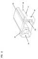
- FIG. 1is a perspective view of a media converter housing according to a preferred embodiment of the present invention.
- FIG. 2is a perspective view of the front housing shown in FIG. 1 .
- FIG. 3is a perspective view of the rear housing shown in FIG. 1 .
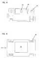
- FIG. 4is a top plan view of the front housing shown in FIG. 2 .
- FIG. 5is a front elevational view of the front housing shown in FIG. 2 .
- FIG. 6is a top plan view of the rear housing shown in FIG. 3 .
- FIG. 7is a bottom plan view of the rear housing shown in FIG. 3 .
- FIG. 8is a perspective view from the front of a circuit assembly according to a preferred embodiment of the present invention.
- FIG. 9is a perspective view from the bottom of the circuit assembly shown in FIG. 8 .
- FIG. 10is a perspective view of an assembled media converter according to a preferred embodiment of the present invention.
- FIG. 11is a perspective back view of the assembled media converter shown in FIG. 10 .
- FIG. 12is a front, perspective view of two converters according to the present invention mounted in a faceplate.
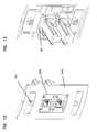
- FIG. 13is a rear, perspective view of two converters according to the present invention mounted in a faceplate.
- FIG. 14is a front perspective view of a circuit assembly according to another preferred embodiment of the present invention.
- FIG. 15is a rear perspective view of the circuit assembly shown in FIG. 14 .
- FIG. 16is a schematic illustration of an adapter used to power the media converter of the present invention.
- FIG. 17is a wiring schematic of the adapter shown in FIG. 16 .
- FIG. 1is a perspective view of a housing assembly for a media converter according to a preferred embodiment of the present invention.
- the media converter housing assembly 10includes a front housing 12 and a rear housing 14 .
- the front housing 12is separate from the rear housing 14 although, in another preferred embodiment they may be formed as an integral piece.
- the front housing 12 and the rear housing 14are coupled together via snap-fit connections 16 which will be described in greater detail hereinafter.
- the front housing 12has a port 18 formed therein to provide access to a connector such as a modular jack such as an RJ-45 jack (not shown).
- the front housing 12also has four ramped tabs 20 , two of which are located on a top surface of the front housing 12 and the other two of which are located on a bottom surface of the housing 12 .
- the ramped tabs 20allow the media converter housing assembly 10 to be retained within a faceplate of a wall outlet as will be described in detail with reference to FIGS. 12 and 13.
- FIG. 2is a perspective view of the front housing 12 shown in FIG. 1 .
- the front housinghas two top tabs 22 and a bottom tab 26 as seen in FIG. 4 .
- Each of the top tabs 22 and bottom tabs 26has a notch 24 formed therein.
- FIG. 4is a top plan view of the front housing shown in FIG. 2 . It can be seen that the bottom tab 26 extends between the top tabs 24 .
- FIG. 5is a front elevational view of the front housing 12 shown in FIG. 2 .
- FIG. 3is a perspective view of the rear housing 14 shown in FIG. 1 .
- the rear housing 14forms a receptacle to receive an adapter circuit assembly (not shown).
- the rear housing 14has an open front 34 and a closed back wall 36 .
- the proximal portion of the rear housing 14has a shoulder region 40 and distal to that is a modified tubular member 38 .
- Formed through a wall of the shoulder region 40are apertures 42 which will be described in detail hereafter.
- the rear housinghas two ramped protrusions 30 located on a top portion of the rear housing 14 in the shoulder region 40 .
- a ramped protrusion 32is formed substantially in the center of a bottom portion of the shoulder region 40 .
- the ramped protrusions 30 of the rear housing 14engage the notches 24 formed in the top tabs 22 of the front housing 12 and the ramped protrusion 32 of the rear housing 14 engages the notch 24 formed in the bottom tab 26 of the front housing 12 to provide the snap-fit connection.
- FIG. 8is a perspective view from the front of a circuit assembly 100 which can be located within housing 10 shown in FIG. 1 .
- FIG. 9is a perspective view from the bottom of the circuit assembly shown in FIG. 8 .
- the circuit assemblyincludes a motherboard 110 , and a daughter board 114 .
- the motherboard 110has electrically coupled thereto two optic fiber connectors 116 via coupling 118 .
- the motherboard 110also has preferably an RJ-45 jack 122 mounted thereon.
- the RJ-45 jack 122is electrically coupled to the motherboard 110 .
- the daughter board 114has, preferably, on one side filters 126 and a converter chip 128 located on the other side.
- the connectors 116are optical type connectors which have a bayonet 130 located on a ferrule 131 of the connector as is well known.
- the daughter board 114is coupled to the motherboard 110 preferably by connectors 124 , which are board interface connectors.
- the circuit assembly 100converts electrical signals received by the RJ-45 jack to optical signals and outputs the optical signal through connectors 116 to a fiber optic cable (not shown), and vice versa.
- the converter 128is a 10BASE-T converter. Because of the novel construction of circuit assembly 100 and housing 10 , daughter board 114 can be removed and replaced with another daughter board 114 having a different converter such as a 100BASE-TX converter thereby allowing the converter to be upgraded.
- circuit assemblyBy making the circuit assembly upgradeable by simply replacing the daughter board, data rates can be increased and protocols may be changed at a reduced cost since the existing circuit assembly need not be replaced with a new one.
- FIG. 10is a front perspective view of an assembled media converter 200 according to a preferred embodiment of the present invention. It can be seen that the rear housing 14 and the front housing 12 are coupled together by the ramped protrusions 30 engaging the notches 24 formed in the top tabs 22 of the front housing 12 and the ramped protrusion 32 formed in the rear housing 14 engaging notch 24 formed in the bottom tab 26 of the front housing 12 which cannot be seen.
- the RJ-45 jack 122is accessible through the port 18 formed in the front housing 12 .
- the optic fiber connectors 116extend through the apertures 42 formed in the shoulder region 40 of the rear housing 14 so as to be exterior to the housing.
- an ST fiber connector 202is coupled to each of the optic fiber connectors 116 via a coupler 204 .
- the coupler 204has a groove 206 which engages the bayonet 130 of each optic fiber connector 116 as is well known to those of ordinary skill in the art.
- FIG. 11is a rear perspective view of the assembled media converter 200 shown in FIG. 10 . From this view the closed back wall 36 of the rear housing 14 can be seen as well as the optic fiber connectors extending through the apertures 42 in the shoulder region 40 of the rear housing 14 .
- FIGS. 12 and 13show a front and rear perspective view of two converters 200 according to the present invention mounted in a faceplate.
- the faceplate 220has two apertures 222 sized to receive the converters therein.
- the faceplate 220includes holes 224 that allow the faceplate 220 to be bolted, screwed or otherwise connected to a wall.
- the ramped tabs 20 located on the front housing 10are depressed and once they pass through the opening, they snap back to original shape and engage the faceplate 220 to hold the converter 200 therein as can be seen in FIG. 12 .
- the converter 200fits into a 6000 MULTI MEDIA OUTLET commercially available from ADC of Minneapolis, Minn.
- FIGS. 14 and 15are front and rear perspective views respectively of a circuit assembly 300 according to another preferred embodiment of the present invention.
- the circuit assembly 300includes a first motherboard 310 , a second motherboard 312 , and a daughter board 314 .
- the first motherboard 310has an aperture 320 formed therein through which a jack 322 such as an RJ-45 jack fits.
- the jack 322is electrically coupled to the second motherboard 312 .
- Electrically coupled to the first motherboard 310 through couplings 318are two optic fiber connectors 316 .
- the ferrules 331 of the fiber optic connectors 316extend through apertures 324 formed in the second motherboard 312 .
- the daughter board 314is electrically coupled to the second motherboard by connectors 332 located on both the daughter board 314 and second motherboard 312 .
- the present inventionhas been described as a media converter that converts between electrical and optical signals, the present invention is not limited to that particular converter.
- the RJ-45 jackcan be replaced with a coaxial connector.
- the optic connectorsmay be coupled to single mode or multimode fiber.
- optical to optical convertersmay be used. Thus, conversions may be made between copper and fiber and fiber and fiber.
- FIG. 16is a schematic illustration of an adapter 400 used to power the media converter of the present invention.
- the adapteris a device that consists of a plastic housing, a printed circuit board (not shown), two miniature DIN connectors 406 , 408 , two RJ-45 jacks 402 , 404 , a resistor (not shown), and an LED 410 . All of the connectors and components are assembled onto the printed circuit board.
- the plastic housingis designed to encase the printed circuit board assembly leaving an opening on each end for access to the miniature DIN connectors 406 , 408 and RJ-45 jacks 402 , 404 to facilitate cable connection.
- the adapter 400is designed to allow an external or ancillary network device such as the media converter of the present invention to receive power via the unused conductors in a RJ-45 patch cord 412 .
- Poweris obtained from a PC mouse port (not shown) coupled to the adapter 400 via RJ-45 cable 414 . This is accomplished by coupling the PC mouse port 406 and the port from a network interface card 402 through the adapter 400 .
- the mouse port 406is connected to the adapter 400 via a 1 m, 6-conductor cable 416 using male miniature DIN connectors 418 on each end.
- the network interface card port(not shown) is connected to port 402 via a 1 m RJ-45 patch cord 414 .
- Ports 402 , 406provide the PC inputs to the adapter 400 .
- the PC mouse 420 or pointing deviceis connected to the adapter 400 on the output side through port 408 .
- the external or ancillary network devicesuch as the media converter 400 is connected to the adapter via a standard RJ-45 patch cord 412 .
- FIG. 17is a wiring schematic of the adapter shown in FIG. 16 .
- the interconnection of the connectors through port 408is accomplished by conductor traces 422 according to the present invention on a printed circuit board 424 .
- the signal pins for the DIN connectors 402 - 408are passed through on pin-for-pin basis.
- the +5VDC (pin 4 ) 426 and GROUND (pin 3 ) 428 from the mouse port 406 , 408 and RJ-45 jacks 402 , 404are tapped and connected to the unused pins 430 of the output RJ-45 jack 404 . Since most local area network systems require only two pairs, one for transmit and one for receive, the unused pairs are used to supply +5VDC and GROUND to an external or ancillary network device such as a media converter according to the present invention.
- An LED indicator 410is visible on one side of the adapter 400 .
- the LED 410is powered by the +5VDC obtained from the PC mouse port 406 and serves as a “power on” indicator.
- the adapter 400allows an external or ancillary network device to be powered from a PC without the use of an external power supply and without the need for a secondary power cord.
- external or ancillary devicescan be powered up to 90 meters away from the PC. This allows the external device to be located anywhere within the standard cable limits as defined by TIA/EIA 568B. Providing power by this technique is also a safety improvement. Since no external power supply is required, the external device is only active when the PC is powered up. When the PC is powered down, so is the remote device.
- the elimination of the external power supplyreduces the number extra AC outlets required in the vicinity of the PC. This reduces cost, workstation clutter, and congestion in cable raceways, especially in modular furniture applications.
Landscapes
- Physics & Mathematics (AREA)
- General Physics & Mathematics (AREA)
- Optics & Photonics (AREA)
- Details Of Connecting Devices For Male And Female Coupling (AREA)
- Input Circuits Of Receivers And Coupling Of Receivers And Audio Equipment (AREA)
- Connector Housings Or Holding Contact Members (AREA)
- Coupling Device And Connection With Printed Circuit (AREA)
Abstract
Description
Claims (30)
Priority Applications (5)
| Application Number | Priority Date | Filing Date | Title |
|---|---|---|---|
| US09/636,122US6364535B1 (en) | 2000-08-10 | 2000-08-10 | Upgradeable media wall converter and housing |
| PCT/US2001/041477WO2002013333A2 (en) | 2000-08-10 | 2001-07-30 | Upgradeable media wall converter and housing |
| AU2001281370AAU2001281370A1 (en) | 2000-08-10 | 2001-07-30 | Upgradeable media wall converter and housing |
| TW090119513ATW504868B (en) | 2000-08-10 | 2001-08-09 | Upgradeable media wall converter and housing |
| ARP010103854AAR030349A1 (en) | 2000-08-10 | 2001-08-10 | ACCOMMODATION OF UPDATED MEDIUM WALL CONVERTER |
Applications Claiming Priority (1)
| Application Number | Priority Date | Filing Date | Title |
|---|---|---|---|
| US09/636,122US6364535B1 (en) | 2000-08-10 | 2000-08-10 | Upgradeable media wall converter and housing |
Publications (1)
| Publication Number | Publication Date |
|---|---|
| US6364535B1true US6364535B1 (en) | 2002-04-02 |
Family
ID=24550523
Family Applications (1)
| Application Number | Title | Priority Date | Filing Date |
|---|---|---|---|
| US09/636,122Expired - LifetimeUS6364535B1 (en) | 2000-08-10 | 2000-08-10 | Upgradeable media wall converter and housing |
Country Status (5)
| Country | Link |
|---|---|
| US (1) | US6364535B1 (en) |
| AR (1) | AR030349A1 (en) |
| AU (1) | AU2001281370A1 (en) |
| TW (1) | TW504868B (en) |
| WO (1) | WO2002013333A2 (en) |
Cited By (30)
| Publication number | Priority date | Publication date | Assignee | Title |
|---|---|---|---|---|
| US20020159402A1 (en)* | 1998-07-28 | 2002-10-31 | Yehuda Binder | Local area network of serial intelligent cells |
| US20020178411A1 (en)* | 2001-05-28 | 2002-11-28 | Yoshimi Kohda | Media converter and failure detection technique |
| US20030103335A1 (en)* | 2001-12-04 | 2003-06-05 | Skradde Steven W. | Housing for telecommunications equipment |
| US6600611B2 (en)* | 2001-09-28 | 2003-07-29 | Sumitomo Electric Industries, Ltd. | Optical module |
| WO2004010755A1 (en)* | 2002-07-18 | 2004-01-29 | Adc Telecommunication, Inc. | Media wall converter and housing |
| US6794577B1 (en)* | 2003-03-27 | 2004-09-21 | International Business Machines Corporation | Configurable cable for use in a data processing network |
| US20050025162A1 (en)* | 2002-11-13 | 2005-02-03 | Yehuda Binder | Addressable outlet, and a network using same |
| US20050136731A1 (en)* | 2002-04-15 | 2005-06-23 | Brown Curtis D. | Serial-to-ethernet conversion port |
| US20060182094A1 (en)* | 2000-04-18 | 2006-08-17 | Serconet Ltd. | Telephone communication system over a single telephone line |
| US20060197428A1 (en)* | 2005-02-21 | 2006-09-07 | Takeshi Tonegawa | Electron devices with non-evaporation-type getters and method for manufacturing the same |
| US20070010132A1 (en)* | 2005-07-11 | 2007-01-11 | Finisar Corporation | Media converter |
| US20070058666A1 (en)* | 2005-08-09 | 2007-03-15 | Adc Telecommunications, Inc. | Wall-mountable connector |
| US20070070911A1 (en)* | 2005-09-29 | 2007-03-29 | Goldberg Keith J | Method for testing links in a wireless network |
| EP1783521A1 (en)* | 2005-11-02 | 2007-05-09 | TKM Telekommunikation und Elektronik GmbH | Connector and RJ-45 connexion system. |
| US20070161283A1 (en)* | 2003-09-30 | 2007-07-12 | John Kerry | Telecommunications connection apparatus |
| US20070238360A1 (en)* | 2005-12-01 | 2007-10-11 | Adc Telecommunications, Inc. | Connector including media converter |
| US20080219430A1 (en)* | 2004-02-16 | 2008-09-11 | Serconet Ltd. | Outlet add-on module |
| US7453895B2 (en) | 2001-10-11 | 2008-11-18 | Serconet Ltd | Outlet with analog signal adapter, a method for use thereof and a network using said outlet |
| US7483524B2 (en) | 1999-07-20 | 2009-01-27 | Serconet, Ltd | Network for telephony and data communication |
| US7530818B1 (en)* | 2008-02-28 | 2009-05-12 | Sure-Fire Electrical Corporation | Signal adaptor box |
| WO2008094727A3 (en)* | 2007-01-31 | 2010-01-21 | Cisco Technology, Inc. | Rj style connector to eliminate cable electrostatic discharge events |
| US7680255B2 (en) | 2001-07-05 | 2010-03-16 | Mosaid Technologies Incorporated | Telephone outlet with packet telephony adaptor, and a network using same |
| US7686653B2 (en) | 2003-09-07 | 2010-03-30 | Mosaid Technologies Incorporated | Modular outlet |
| US7873058B2 (en) | 2004-11-08 | 2011-01-18 | Mosaid Technologies Incorporated | Outlet with analog signal adapter, a method for use thereof and a network using said outlet |
| US20110044693A1 (en)* | 2008-01-04 | 2011-02-24 | Bradley George Kelly | System and apparatus for providing a high quality of service network connection via plastic optical fiber |
| US8363797B2 (en) | 2000-03-20 | 2013-01-29 | Mosaid Technologies Incorporated | Telephone outlet for implementing a local area network over telephone lines and a local area network using such outlets |
| US8582598B2 (en) | 1999-07-07 | 2013-11-12 | Mosaid Technologies Incorporated | Local area network for distributing data communication, sensing and control signals |
| EP3255738A1 (en)* | 2016-06-10 | 2017-12-13 | Dawon DNS Co., Ltd | Smart plug socket device |
| US10986165B2 (en) | 2004-01-13 | 2021-04-20 | May Patents Ltd. | Information device |
| US20220295161A1 (en)* | 2021-02-02 | 2022-09-15 | C5 Holdings, Llc | System and method for providing a data network |
Families Citing this family (2)
| Publication number | Priority date | Publication date | Assignee | Title |
|---|---|---|---|---|
| EP2425503A1 (en)* | 2009-04-28 | 2012-03-07 | Firecomms Limited | A connector |
| USD862389S1 (en)* | 2017-03-10 | 2019-10-08 | Norman R. Byrne | Low voltage outlet |
Citations (5)
| Publication number | Priority date | Publication date | Assignee | Title |
|---|---|---|---|---|
| US4526431A (en)* | 1983-02-14 | 1985-07-02 | Nec Corporation | Connector with mechanism for coupling and uncoupling plurality of blocks |
| US5104243A (en)* | 1990-04-23 | 1992-04-14 | E. I. Du Pont De Nemours And Company | Device for electro-optical signal conversion |
| US5767999A (en)* | 1996-05-02 | 1998-06-16 | Vixel Corporation | Hot-pluggable/interchangeable circuit module and universal guide system having a standard form factor |
| US6178096B1 (en)* | 1998-11-25 | 2001-01-23 | The Whitaker Corporation | Shielding cover having parts held together by latch members |
| US6220873B1 (en)* | 1999-08-10 | 2001-04-24 | Stratos Lightwave, Inc. | Modified contact traces for interface converter |
Family Cites Families (8)
| Publication number | Priority date | Publication date | Assignee | Title |
|---|---|---|---|---|
| FR2690758A1 (en)* | 1992-04-29 | 1993-11-05 | Cit Alcatel | Optical link termination device. |
| US5333221A (en)* | 1992-06-30 | 1994-07-26 | The Whitaker Corporation | Universal adapter for optical connectors |
| FR2718893B1 (en)* | 1994-04-15 | 1996-07-12 | Jacques Nozick | Adaptable socket for standard wiring, for communication system. |
| US5647767A (en)* | 1995-02-06 | 1997-07-15 | The Whitaker Corporation | Electrical connector jack assembly for signal transmission |
| US5687233A (en)* | 1996-02-09 | 1997-11-11 | Maxconn Incorporated | Modular jack having built-in circuitry |
| DE29800978U1 (en)* | 1998-01-22 | 1998-05-14 | Niebuhr Optoelektronik GmbH, 21079 Hamburg | Opto-electronic connector |
| US6204948B1 (en)* | 1998-07-02 | 2001-03-20 | Ortronics, Inc. | Media converter |
| US6381283B1 (en)* | 1998-10-07 | 2002-04-30 | Controlnet, Inc. | Integrated socket with chip carrier |
- 2000
- 2000-08-10USUS09/636,122patent/US6364535B1/ennot_activeExpired - Lifetime
- 2001
- 2001-07-30AUAU2001281370Apatent/AU2001281370A1/ennot_activeAbandoned
- 2001-07-30WOPCT/US2001/041477patent/WO2002013333A2/enactiveApplication Filing
- 2001-08-09TWTW090119513Apatent/TW504868B/enactive
- 2001-08-10ARARP010103854Apatent/AR030349A1/enunknown
Patent Citations (5)
| Publication number | Priority date | Publication date | Assignee | Title |
|---|---|---|---|---|
| US4526431A (en)* | 1983-02-14 | 1985-07-02 | Nec Corporation | Connector with mechanism for coupling and uncoupling plurality of blocks |
| US5104243A (en)* | 1990-04-23 | 1992-04-14 | E. I. Du Pont De Nemours And Company | Device for electro-optical signal conversion |
| US5767999A (en)* | 1996-05-02 | 1998-06-16 | Vixel Corporation | Hot-pluggable/interchangeable circuit module and universal guide system having a standard form factor |
| US6178096B1 (en)* | 1998-11-25 | 2001-01-23 | The Whitaker Corporation | Shielding cover having parts held together by latch members |
| US6220873B1 (en)* | 1999-08-10 | 2001-04-24 | Stratos Lightwave, Inc. | Modified contact traces for interface converter |
Cited By (111)
| Publication number | Priority date | Publication date | Assignee | Title |
|---|---|---|---|---|
| US20060018339A1 (en)* | 1998-07-28 | 2006-01-26 | Serconet, Ltd | Local area network of serial intelligent cells |
| US20060251110A1 (en)* | 1998-07-28 | 2006-11-09 | Isreali Company Of Serconet Ltd. | Local area network of serial intelligent cells |
| US7653015B2 (en) | 1998-07-28 | 2010-01-26 | Mosaid Technologies Incorporated | Local area network of serial intelligent cells |
| US7965735B2 (en) | 1998-07-28 | 2011-06-21 | Mosaid Technologies Incorporated | Local area network of serial intelligent cells |
| US7978726B2 (en) | 1998-07-28 | 2011-07-12 | Mosaid Technologies Incorporated | Local area network of serial intelligent cells |
| US20040170189A1 (en)* | 1998-07-28 | 2004-09-02 | Israeli Company Of Serconet Ltd. | Local area network of serial intellegent cells |
| US20040174897A1 (en)* | 1998-07-28 | 2004-09-09 | Israeli Company Of Serconet Ltd. | Local area network of serial intellegent cells |
| US7292600B2 (en) | 1998-07-28 | 2007-11-06 | Serconet Ltd. | Local area network of serial intellegent cells |
| US8908673B2 (en) | 1998-07-28 | 2014-12-09 | Conversant Intellectual Property Management Incorporated | Local area network of serial intelligent cells |
| US7830858B2 (en) | 1998-07-28 | 2010-11-09 | Mosaid Technologies Incorporated | Local area network of serial intelligent cells |
| US7016368B2 (en) | 1998-07-28 | 2006-03-21 | Serconet, Ltd. | Local area network of serial intelligent cells |
| US8885659B2 (en) | 1998-07-28 | 2014-11-11 | Conversant Intellectual Property Management Incorporated | Local area network of serial intelligent cells |
| US7187695B2 (en) | 1998-07-28 | 2007-03-06 | Serconet Ltd. | Local area network of serial intelligent cells |
| US7986708B2 (en) | 1998-07-28 | 2011-07-26 | Mosaid Technologies Incorporated | Local area network of serial intelligent cells |
| US20050163152A1 (en)* | 1998-07-28 | 2005-07-28 | Serconet Ltd. | Local area network of serial intelligent cells |
| US20060018338A1 (en)* | 1998-07-28 | 2006-01-26 | Serconet, Ltd. | Local area network of serial intelligent cells |
| US7852874B2 (en) | 1998-07-28 | 2010-12-14 | Mosaid Technologies Incorporated | Local area network of serial intelligent cells |
| US7006523B2 (en) | 1998-07-28 | 2006-02-28 | Serconet Ltd. | Local area network of serial intelligent cells |
| US20050013320A1 (en)* | 1998-07-28 | 2005-01-20 | Serconet Ltd. | Local area network of serial intelligent cells |
| US20020159402A1 (en)* | 1998-07-28 | 2002-10-31 | Yehuda Binder | Local area network of serial intelligent cells |
| US7035280B2 (en) | 1998-07-28 | 2006-04-25 | Serconet Ltd. | Local area network of serial intelligent cells |
| US7424031B2 (en) | 1998-07-28 | 2008-09-09 | Serconet, Ltd. | Local area network of serial intelligent cells |
| US7095756B2 (en) | 1998-07-28 | 2006-08-22 | Serconet, Ltd. | Local area network of serial intelligent cells |
| US8885660B2 (en) | 1998-07-28 | 2014-11-11 | Conversant Intellectual Property Management Incorporated | Local area network of serial intelligent cells |
| US8270430B2 (en) | 1998-07-28 | 2012-09-18 | Mosaid Technologies Incorporated | Local area network of serial intelligent cells |
| US7221679B2 (en) | 1998-07-28 | 2007-05-22 | Serconet Ltd. | Local area network of serial intelligent cells |
| US20060291497A1 (en)* | 1998-07-28 | 2006-12-28 | Israeli Company Of Serconet Ltd. | Local area network of serial intelligent cells |
| US8867523B2 (en) | 1998-07-28 | 2014-10-21 | Conversant Intellectual Property Management Incorporated | Local area network of serial intelligent cells |
| US8325636B2 (en) | 1998-07-28 | 2012-12-04 | Mosaid Technologies Incorporated | Local area network of serial intelligent cells |
| US8582598B2 (en) | 1999-07-07 | 2013-11-12 | Mosaid Technologies Incorporated | Local area network for distributing data communication, sensing and control signals |
| US7483524B2 (en) | 1999-07-20 | 2009-01-27 | Serconet, Ltd | Network for telephony and data communication |
| US7492875B2 (en) | 1999-07-20 | 2009-02-17 | Serconet, Ltd. | Network for telephony and data communication |
| US8929523B2 (en) | 1999-07-20 | 2015-01-06 | Conversant Intellectual Property Management Inc. | Network for telephony and data communication |
| US8351582B2 (en) | 1999-07-20 | 2013-01-08 | Mosaid Technologies Incorporated | Network for telephony and data communication |
| US8855277B2 (en) | 2000-03-20 | 2014-10-07 | Conversant Intellectual Property Managment Incorporated | Telephone outlet for implementing a local area network over telephone lines and a local area network using such outlets |
| US8363797B2 (en) | 2000-03-20 | 2013-01-29 | Mosaid Technologies Incorporated | Telephone outlet for implementing a local area network over telephone lines and a local area network using such outlets |
| US20080043646A1 (en)* | 2000-04-18 | 2008-02-21 | Serconet Ltd. | Telephone communication system over a single telephone line |
| US8559422B2 (en) | 2000-04-18 | 2013-10-15 | Mosaid Technologies Incorporated | Telephone communication system over a single telephone line |
| US7197028B2 (en) | 2000-04-18 | 2007-03-27 | Serconet Ltd. | Telephone communication system over a single telephone line |
| US7466722B2 (en) | 2000-04-18 | 2008-12-16 | Serconet Ltd | Telephone communication system over a single telephone line |
| US7397791B2 (en) | 2000-04-18 | 2008-07-08 | Serconet, Ltd. | Telephone communication system over a single telephone line |
| US20060182094A1 (en)* | 2000-04-18 | 2006-08-17 | Serconet Ltd. | Telephone communication system over a single telephone line |
| US8223800B2 (en) | 2000-04-18 | 2012-07-17 | Mosaid Technologies Incorporated | Telephone communication system over a single telephone line |
| US8000349B2 (en) | 2000-04-18 | 2011-08-16 | Mosaid Technologies Incorporated | Telephone communication system over a single telephone line |
| US7593394B2 (en) | 2000-04-18 | 2009-09-22 | Mosaid Technologies Incorporated | Telephone communication system over a single telephone line |
| US20020178411A1 (en)* | 2001-05-28 | 2002-11-28 | Yoshimi Kohda | Media converter and failure detection technique |
| US6839872B2 (en)* | 2001-05-28 | 2005-01-04 | Allied Telesis Kabushiki Kaisha | Media converter and failure detection technique |
| US7680255B2 (en) | 2001-07-05 | 2010-03-16 | Mosaid Technologies Incorporated | Telephone outlet with packet telephony adaptor, and a network using same |
| US6600611B2 (en)* | 2001-09-28 | 2003-07-29 | Sumitomo Electric Industries, Ltd. | Optical module |
| US7453895B2 (en) | 2001-10-11 | 2008-11-18 | Serconet Ltd | Outlet with analog signal adapter, a method for use thereof and a network using said outlet |
| US7953071B2 (en) | 2001-10-11 | 2011-05-31 | Mosaid Technologies Incorporated | Outlet with analog signal adapter, a method for use thereof and a network using said outlet |
| US7889720B2 (en) | 2001-10-11 | 2011-02-15 | Mosaid Technologies Incorporated | Outlet with analog signal adapter, a method for use thereof and a network using said outlet |
| US7860084B2 (en) | 2001-10-11 | 2010-12-28 | Mosaid Technologies Incorporated | Outlet with analog signal adapter, a method for use thereof and a network using said outlet |
| US8433054B2 (en) | 2001-12-04 | 2013-04-30 | Adc Telecommunications, Inc. | Housing for telecommunications equipment |
| US20030103335A1 (en)* | 2001-12-04 | 2003-06-05 | Skradde Steven W. | Housing for telecommunications equipment |
| US7110527B2 (en)* | 2001-12-04 | 2006-09-19 | Adc Telecommunications, Inc. | Housing for telecommunications equipment |
| US20070036335A1 (en)* | 2001-12-04 | 2007-02-15 | Adc Telecommunications, Inc. | Housing for telecommunications equipment |
| US20050136731A1 (en)* | 2002-04-15 | 2005-06-23 | Brown Curtis D. | Serial-to-ethernet conversion port |
| US7018242B2 (en)* | 2002-04-15 | 2006-03-28 | Lantronix, Inc. | Serial-to-ethernet conversion port |
| US6854895B2 (en) | 2002-07-18 | 2005-02-15 | Adc Telecommunications, Inc. | Media wall converter and housing |
| WO2004010755A1 (en)* | 2002-07-18 | 2004-01-29 | Adc Telecommunication, Inc. | Media wall converter and housing |
| US7990908B2 (en) | 2002-11-13 | 2011-08-02 | Mosaid Technologies Incorporated | Addressable outlet, and a network using the same |
| US7522615B2 (en) | 2002-11-13 | 2009-04-21 | Serconet, Ltd. | Addressable outlet, and a network using same |
| US8295185B2 (en) | 2002-11-13 | 2012-10-23 | Mosaid Technologies Inc. | Addressable outlet for use in wired local area network |
| US20050025162A1 (en)* | 2002-11-13 | 2005-02-03 | Yehuda Binder | Addressable outlet, and a network using same |
| US7911992B2 (en) | 2002-11-13 | 2011-03-22 | Mosaid Technologies Incorporated | Addressable outlet, and a network using the same |
| US6794577B1 (en)* | 2003-03-27 | 2004-09-21 | International Business Machines Corporation | Configurable cable for use in a data processing network |
| US20040188129A1 (en)* | 2003-03-27 | 2004-09-30 | International Business Machines Corporation | Configurable cable for use in a data processing network |
| US7688841B2 (en) | 2003-07-09 | 2010-03-30 | Mosaid Technologies Incorporated | Modular outlet |
| US7867035B2 (en) | 2003-07-09 | 2011-01-11 | Mosaid Technologies Incorporated | Modular outlet |
| US7873062B2 (en) | 2003-07-09 | 2011-01-18 | Mosaid Technologies Incorporated | Modular outlet |
| US8360810B2 (en) | 2003-09-07 | 2013-01-29 | Mosaid Technologies Incorporated | Modular outlet |
| US8092258B2 (en) | 2003-09-07 | 2012-01-10 | Mosaid Technologies Incorporated | Modular outlet |
| US8591264B2 (en) | 2003-09-07 | 2013-11-26 | Mosaid Technologies Incorporated | Modular outlet |
| US7686653B2 (en) | 2003-09-07 | 2010-03-30 | Mosaid Technologies Incorporated | Modular outlet |
| US7690949B2 (en) | 2003-09-07 | 2010-04-06 | Mosaid Technologies Incorporated | Modular outlet |
| US8235755B2 (en) | 2003-09-07 | 2012-08-07 | Mosaid Technologies Incorporated | Modular outlet |
| US20070161283A1 (en)* | 2003-09-30 | 2007-07-12 | John Kerry | Telecommunications connection apparatus |
| US7507030B2 (en)* | 2003-09-30 | 2009-03-24 | British Telecommunications Public Limited Company | Slim profile telecommunications connection apparatus |
| US10986165B2 (en) | 2004-01-13 | 2021-04-20 | May Patents Ltd. | Information device |
| US7881462B2 (en) | 2004-02-16 | 2011-02-01 | Mosaid Technologies Incorporated | Outlet add-on module |
| US20080227333A1 (en)* | 2004-02-16 | 2008-09-18 | Serconet Ltd. | Outlet add-on module |
| US8542819B2 (en) | 2004-02-16 | 2013-09-24 | Mosaid Technologies Incorporated | Outlet add-on module |
| US20080231111A1 (en)* | 2004-02-16 | 2008-09-25 | Serconet Ltd. | Outlet add-on module |
| US20080219430A1 (en)* | 2004-02-16 | 2008-09-11 | Serconet Ltd. | Outlet add-on module |
| US7756268B2 (en) | 2004-02-16 | 2010-07-13 | Mosaid Technologies Incorporated | Outlet add-on module |
| US8243918B2 (en) | 2004-02-16 | 2012-08-14 | Mosaid Technologies Incorporated | Outlet add-on module |
| US8565417B2 (en) | 2004-02-16 | 2013-10-22 | Mosaid Technologies Incorporated | Outlet add-on module |
| US8611528B2 (en) | 2004-02-16 | 2013-12-17 | Mosaid Technologies Incorporated | Outlet add-on module |
| US7873058B2 (en) | 2004-11-08 | 2011-01-18 | Mosaid Technologies Incorporated | Outlet with analog signal adapter, a method for use thereof and a network using said outlet |
| US20060197428A1 (en)* | 2005-02-21 | 2006-09-07 | Takeshi Tonegawa | Electron devices with non-evaporation-type getters and method for manufacturing the same |
| US20070010132A1 (en)* | 2005-07-11 | 2007-01-11 | Finisar Corporation | Media converter |
| US7331819B2 (en)* | 2005-07-11 | 2008-02-19 | Finisar Corporation | Media converter |
| US20070058666A1 (en)* | 2005-08-09 | 2007-03-15 | Adc Telecommunications, Inc. | Wall-mountable connector |
| US8509261B2 (en) | 2005-08-09 | 2013-08-13 | Adc Telecommunications, Inc. | Wall-mountable media converter |
| US8036231B2 (en) | 2005-08-09 | 2011-10-11 | Adc Telecommunications, Inc. | Wall-mountable connector |
| US20070070911A1 (en)* | 2005-09-29 | 2007-03-29 | Goldberg Keith J | Method for testing links in a wireless network |
| US7326087B2 (en) | 2005-11-02 | 2008-02-05 | Tkm Telekommunikation Und Elektronik Gmbh | Plug-in connector and coupling in the form of an RJ45 connector jack |
| US20070105452A1 (en)* | 2005-11-02 | 2007-05-10 | Bernd Gerlach | Plug-in connector and coupling in the form of an RJ45 connector jack |
| EP1783521A1 (en)* | 2005-11-02 | 2007-05-09 | TKM Telekommunikation und Elektronik GmbH | Connector and RJ-45 connexion system. |
| US7938686B2 (en) | 2005-12-01 | 2011-05-10 | Adc Telecommunications, Inc. | Connector including media converter |
| US7458855B2 (en)* | 2005-12-01 | 2008-12-02 | Adc Telecommunications, Inc. | Connector including media converter |
| US20070238360A1 (en)* | 2005-12-01 | 2007-10-11 | Adc Telecommunications, Inc. | Connector including media converter |
| US20090191759A1 (en)* | 2005-12-01 | 2009-07-30 | Adc Telecommunications, Inc. | Connector including media converter |
| CN101999193A (en)* | 2007-01-31 | 2011-03-30 | 思科技术公司 | RJ style connector to eliminate cable electrostatic discharge events |
| WO2008094727A3 (en)* | 2007-01-31 | 2010-01-21 | Cisco Technology, Inc. | Rj style connector to eliminate cable electrostatic discharge events |
| US20110044693A1 (en)* | 2008-01-04 | 2011-02-24 | Bradley George Kelly | System and apparatus for providing a high quality of service network connection via plastic optical fiber |
| US7530818B1 (en)* | 2008-02-28 | 2009-05-12 | Sure-Fire Electrical Corporation | Signal adaptor box |
| EP3255738A1 (en)* | 2016-06-10 | 2017-12-13 | Dawon DNS Co., Ltd | Smart plug socket device |
| US20220295161A1 (en)* | 2021-02-02 | 2022-09-15 | C5 Holdings, Llc | System and method for providing a data network |
| US12126946B2 (en)* | 2021-02-02 | 2024-10-22 | Ifp Connect, Llc | System and method for providing a data network |
Also Published As
| Publication number | Publication date |
|---|---|
| AR030349A1 (en) | 2003-08-20 |
| WO2002013333A3 (en) | 2002-05-02 |
| WO2002013333A2 (en) | 2002-02-14 |
| AU2001281370A1 (en) | 2002-02-18 |
| WO2002013333A9 (en) | 2003-02-06 |
| TW504868B (en) | 2002-10-01 |
Similar Documents
| Publication | Publication Date | Title |
|---|---|---|
| US6364535B1 (en) | Upgradeable media wall converter and housing | |
| US6854895B2 (en) | Media wall converter and housing | |
| US11531169B2 (en) | Adapter system for multi-fiber mechanical transfer type ferrule | |
| US7494287B2 (en) | Integrated optical fiber and electro-optical converter | |
| US8419444B2 (en) | Adapter for high-speed ethernet | |
| US8794850B2 (en) | Adapter configured with both optical and electrical connections for providing both optical and electrical communications capabilities | |
| US7934959B2 (en) | Adapter for pluggable module | |
| US5473715A (en) | Hybrid fiber optic/electrical connector | |
| CA2621016C (en) | Digital signal media conversion panel | |
| US6802737B2 (en) | Modular connection system for ethernet applications in the industrial sector | |
| US9196999B2 (en) | Two-part modular connector and smart managed interconnect link using the two-part modular connector | |
| CN101449190B (en) | Fiber Optic Cables and Fiber Optic Cable Assemblies for Wireless Access | |
| CA2332780C (en) | Interconnection system for optical circuit boards | |
| US20010053624A1 (en) | High speed interface converter module | |
| US9525255B2 (en) | Low profile faceplate having managed connectivity | |
| CN110546822A (en) | Connectors for single twisted conductor pairs | |
| US20070270044A1 (en) | High Speed Modular Jack | |
| CN101015143B (en) | Multi-Channel Optical Transceiver Module | |
| US6146153A (en) | Adapter apparatus and method for transmitting electronic data | |
| GB2334592A (en) | Adapter for coupling optical fibre and electronic circuits | |
| CN212623217U (en) | Optical module | |
| US6517252B2 (en) | Optical connector | |
| JP2002216883A (en) | Connection cable | |
| CN112510397A (en) | High-speed electric connector | |
| WO1993015465A1 (en) | User configurable media interface for network computer products |
Legal Events
| Date | Code | Title | Description |
|---|---|---|---|
| AS | Assignment | Owner name:ADC, MINNESOTA Free format text:ASSIGNMENT OF ASSIGNORS INTEREST;ASSIGNOR:COFFEY, JOSEPH;REEL/FRAME:011319/0456 Effective date:20001106 | |
| STCF | Information on status: patent grant | Free format text:PATENTED CASE | |
| FPAY | Fee payment | Year of fee payment:4 | |
| FPAY | Fee payment | Year of fee payment:8 | |
| FPAY | Fee payment | Year of fee payment:12 | |
| AS | Assignment | Owner name:ADC TELECOMMUNICATIONS, INC., PENNSYLVANIA Free format text:CORRECTIVE ASSIGNMENT TO CORRECT THE ASSIGNEE NAME PREVIOUSLY RECORDED AT REEL: 011319 FRAME: 0456. ASSIGNOR(S) HEREBY CONFIRMS THE ASSIGNMENT;ASSIGNOR:COFFEY, JOSEPH C.;REEL/FRAME:036170/0554 Effective date:20150624 | |
| AS | Assignment | Owner name:TYCO ELECTRONICS SERVICES GMBH, SWITZERLAND Free format text:ASSIGNMENT OF ASSIGNORS INTEREST;ASSIGNOR:ADC TELECOMMUNICATIONS, INC.;REEL/FRAME:036327/0695 Effective date:20110930 | |
| AS | Assignment | Owner name:COMMSCOPE EMEA LIMITED, IRELAND Free format text:ASSIGNMENT OF ASSIGNORS INTEREST;ASSIGNOR:TYCO ELECTRONICS SERVICES GMBH;REEL/FRAME:036956/0001 Effective date:20150828 | |
| AS | Assignment | Owner name:COMMSCOPE TECHNOLOGIES LLC, NORTH CAROLINA Free format text:ASSIGNMENT OF ASSIGNORS INTEREST;ASSIGNOR:COMMSCOPE EMEA LIMITED;REEL/FRAME:037012/0001 Effective date:20150828 | |
| AS | Assignment | Owner name:JPMORGAN CHASE BANK, N.A., AS COLLATERAL AGENT, ILLINOIS Free format text:PATENT SECURITY AGREEMENT (TERM);ASSIGNOR:COMMSCOPE TECHNOLOGIES LLC;REEL/FRAME:037513/0709 Effective date:20151220 Owner name:JPMORGAN CHASE BANK, N.A., AS COLLATERAL AGENT, ILLINOIS Free format text:PATENT SECURITY AGREEMENT (ABL);ASSIGNOR:COMMSCOPE TECHNOLOGIES LLC;REEL/FRAME:037514/0196 Effective date:20151220 Owner name:JPMORGAN CHASE BANK, N.A., AS COLLATERAL AGENT, IL Free format text:PATENT SECURITY AGREEMENT (TERM);ASSIGNOR:COMMSCOPE TECHNOLOGIES LLC;REEL/FRAME:037513/0709 Effective date:20151220 Owner name:JPMORGAN CHASE BANK, N.A., AS COLLATERAL AGENT, IL Free format text:PATENT SECURITY AGREEMENT (ABL);ASSIGNOR:COMMSCOPE TECHNOLOGIES LLC;REEL/FRAME:037514/0196 Effective date:20151220 | |
| AS | Assignment | Owner name:ANDREW LLC, NORTH CAROLINA Free format text:RELEASE BY SECURED PARTY;ASSIGNOR:JPMORGAN CHASE BANK, N.A.;REEL/FRAME:048840/0001 Effective date:20190404 Owner name:REDWOOD SYSTEMS, INC., NORTH CAROLINA Free format text:RELEASE BY SECURED PARTY;ASSIGNOR:JPMORGAN CHASE BANK, N.A.;REEL/FRAME:048840/0001 Effective date:20190404 Owner name:ALLEN TELECOM LLC, ILLINOIS Free format text:RELEASE BY SECURED PARTY;ASSIGNOR:JPMORGAN CHASE BANK, N.A.;REEL/FRAME:048840/0001 Effective date:20190404 Owner name:COMMSCOPE, INC. OF NORTH CAROLINA, NORTH CAROLINA Free format text:RELEASE BY SECURED PARTY;ASSIGNOR:JPMORGAN CHASE BANK, N.A.;REEL/FRAME:048840/0001 Effective date:20190404 Owner name:COMMSCOPE TECHNOLOGIES LLC, NORTH CAROLINA Free format text:RELEASE BY SECURED PARTY;ASSIGNOR:JPMORGAN CHASE BANK, N.A.;REEL/FRAME:048840/0001 Effective date:20190404 Owner name:ALLEN TELECOM LLC, ILLINOIS Free format text:RELEASE BY SECURED PARTY;ASSIGNOR:JPMORGAN CHASE BANK, N.A.;REEL/FRAME:049260/0001 Effective date:20190404 Owner name:REDWOOD SYSTEMS, INC., NORTH CAROLINA Free format text:RELEASE BY SECURED PARTY;ASSIGNOR:JPMORGAN CHASE BANK, N.A.;REEL/FRAME:049260/0001 Effective date:20190404 Owner name:COMMSCOPE TECHNOLOGIES LLC, NORTH CAROLINA Free format text:RELEASE BY SECURED PARTY;ASSIGNOR:JPMORGAN CHASE BANK, N.A.;REEL/FRAME:049260/0001 Effective date:20190404 Owner name:COMMSCOPE, INC. OF NORTH CAROLINA, NORTH CAROLINA Free format text:RELEASE BY SECURED PARTY;ASSIGNOR:JPMORGAN CHASE BANK, N.A.;REEL/FRAME:049260/0001 Effective date:20190404 Owner name:ANDREW LLC, NORTH CAROLINA Free format text:RELEASE BY SECURED PARTY;ASSIGNOR:JPMORGAN CHASE BANK, N.A.;REEL/FRAME:049260/0001 Effective date:20190404 | |
| AS | Assignment | Owner name:WILMINGTON TRUST, NATIONAL ASSOCIATION, AS COLLATE Free format text:PATENT SECURITY AGREEMENT;ASSIGNOR:COMMSCOPE TECHNOLOGIES LLC;REEL/FRAME:049892/0051 Effective date:20190404 Owner name:JPMORGAN CHASE BANK, N.A., NEW YORK Free format text:ABL SECURITY AGREEMENT;ASSIGNORS:COMMSCOPE, INC. OF NORTH CAROLINA;COMMSCOPE TECHNOLOGIES LLC;ARRIS ENTERPRISES LLC;AND OTHERS;REEL/FRAME:049892/0396 Effective date:20190404 Owner name:JPMORGAN CHASE BANK, N.A., NEW YORK Free format text:TERM LOAN SECURITY AGREEMENT;ASSIGNORS:COMMSCOPE, INC. OF NORTH CAROLINA;COMMSCOPE TECHNOLOGIES LLC;ARRIS ENTERPRISES LLC;AND OTHERS;REEL/FRAME:049905/0504 Effective date:20190404 Owner name:WILMINGTON TRUST, NATIONAL ASSOCIATION, AS COLLATERAL AGENT, CONNECTICUT Free format text:PATENT SECURITY AGREEMENT;ASSIGNOR:COMMSCOPE TECHNOLOGIES LLC;REEL/FRAME:049892/0051 Effective date:20190404 | |
| AS | Assignment | Owner name:RUCKUS WIRELESS, LLC (F/K/A RUCKUS WIRELESS, INC.), NORTH CAROLINA Free format text:RELEASE OF SECURITY INTEREST AT REEL/FRAME 049905/0504;ASSIGNOR:JPMORGAN CHASE BANK, N.A., AS COLLATERAL AGENT;REEL/FRAME:071477/0255 Effective date:20241217 Owner name:COMMSCOPE TECHNOLOGIES LLC, NORTH CAROLINA Free format text:RELEASE OF SECURITY INTEREST AT REEL/FRAME 049905/0504;ASSIGNOR:JPMORGAN CHASE BANK, N.A., AS COLLATERAL AGENT;REEL/FRAME:071477/0255 Effective date:20241217 Owner name:COMMSCOPE, INC. OF NORTH CAROLINA, NORTH CAROLINA Free format text:RELEASE OF SECURITY INTEREST AT REEL/FRAME 049905/0504;ASSIGNOR:JPMORGAN CHASE BANK, N.A., AS COLLATERAL AGENT;REEL/FRAME:071477/0255 Effective date:20241217 Owner name:ARRIS SOLUTIONS, INC., NORTH CAROLINA Free format text:RELEASE OF SECURITY INTEREST AT REEL/FRAME 049905/0504;ASSIGNOR:JPMORGAN CHASE BANK, N.A., AS COLLATERAL AGENT;REEL/FRAME:071477/0255 Effective date:20241217 Owner name:ARRIS TECHNOLOGY, INC., NORTH CAROLINA Free format text:RELEASE OF SECURITY INTEREST AT REEL/FRAME 049905/0504;ASSIGNOR:JPMORGAN CHASE BANK, N.A., AS COLLATERAL AGENT;REEL/FRAME:071477/0255 Effective date:20241217 Owner name:ARRIS ENTERPRISES LLC (F/K/A ARRIS ENTERPRISES, INC.), NORTH CAROLINA Free format text:RELEASE OF SECURITY INTEREST AT REEL/FRAME 049905/0504;ASSIGNOR:JPMORGAN CHASE BANK, N.A., AS COLLATERAL AGENT;REEL/FRAME:071477/0255 Effective date:20241217 |