US6364078B1 - Wheel damping - Google Patents
Wheel dampingDownload PDFInfo
- Publication number
- US6364078B1 US6364078B1US09/140,937US14093798AUS6364078B1US 6364078 B1US6364078 B1US 6364078B1US 14093798 AUS14093798 AUS 14093798AUS 6364078 B1US6364078 B1US 6364078B1
- Authority
- US
- United States
- Prior art keywords
- damping mass
- assembly
- wheel
- damping
- accordance
- Prior art date
- Legal status (The legal status is an assumption and is not a legal conclusion. Google has not performed a legal analysis and makes no representation as to the accuracy of the status listed.)
- Expired - Lifetime
Links
Images


Classifications
- F—MECHANICAL ENGINEERING; LIGHTING; HEATING; WEAPONS; BLASTING
- F16—ENGINEERING ELEMENTS AND UNITS; GENERAL MEASURES FOR PRODUCING AND MAINTAINING EFFECTIVE FUNCTIONING OF MACHINES OR INSTALLATIONS; THERMAL INSULATION IN GENERAL
- F16F—SPRINGS; SHOCK-ABSORBERS; MEANS FOR DAMPING VIBRATION
- F16F9/00—Springs, vibration-dampers, shock-absorbers, or similarly-constructed movement-dampers using a fluid or the equivalent as damping medium
- F16F9/32—Details
- F16F9/34—Special valve constructions; Shape or construction of throttling passages
- F16F9/348—Throttling passages in the form of annular discs or other plate-like elements which may or may not have a spring action, operating in opposite directions or singly, e.g. annular discs positioned on top of the valve or piston body
- B—PERFORMING OPERATIONS; TRANSPORTING
- B60—VEHICLES IN GENERAL
- B60G—VEHICLE SUSPENSION ARRANGEMENTS
- B60G13/00—Resilient suspensions characterised by arrangement, location or type of vibration dampers
- B60G13/16—Resilient suspensions characterised by arrangement, location or type of vibration dampers having dynamic absorbers as main damping means, i.e. spring-mass system vibrating out of phase
- B—PERFORMING OPERATIONS; TRANSPORTING
- B60—VEHICLES IN GENERAL
- B60G—VEHICLE SUSPENSION ARRANGEMENTS
- B60G3/00—Resilient suspensions for a single wheel
- B60G3/01—Resilient suspensions for a single wheel the wheel being mounted for sliding movement, e.g. in or on a vertical guide
- F—MECHANICAL ENGINEERING; LIGHTING; HEATING; WEAPONS; BLASTING
- F16—ENGINEERING ELEMENTS AND UNITS; GENERAL MEASURES FOR PRODUCING AND MAINTAINING EFFECTIVE FUNCTIONING OF MACHINES OR INSTALLATIONS; THERMAL INSULATION IN GENERAL
- F16F—SPRINGS; SHOCK-ABSORBERS; MEANS FOR DAMPING VIBRATION
- F16F7/00—Vibration-dampers; Shock-absorbers
- F16F7/10—Vibration-dampers; Shock-absorbers using inertia effect
- F16F7/104—Vibration-dampers; Shock-absorbers using inertia effect the inertia member being resiliently mounted
- F16F7/116—Vibration-dampers; Shock-absorbers using inertia effect the inertia member being resiliently mounted on metal springs
- F—MECHANICAL ENGINEERING; LIGHTING; HEATING; WEAPONS; BLASTING
- F16—ENGINEERING ELEMENTS AND UNITS; GENERAL MEASURES FOR PRODUCING AND MAINTAINING EFFECTIVE FUNCTIONING OF MACHINES OR INSTALLATIONS; THERMAL INSULATION IN GENERAL
- F16F—SPRINGS; SHOCK-ABSORBERS; MEANS FOR DAMPING VIBRATION
- F16F9/00—Springs, vibration-dampers, shock-absorbers, or similarly-constructed movement-dampers using a fluid or the equivalent as damping medium
- F16F9/32—Details
- F16F9/50—Special means providing automatic damping adjustment, i.e. self-adjustment of damping by particular sliding movements of a valve element, other than flexions or displacement of valve discs; Special means providing self-adjustment of spring characteristics
- F16F9/512—Means responsive to load action, i.e. static load on the damper or dynamic fluid pressure changes in the damper, e.g. due to changes in velocity
- B—PERFORMING OPERATIONS; TRANSPORTING
- B60—VEHICLES IN GENERAL
- B60G—VEHICLE SUSPENSION ARRANGEMENTS
- B60G2200/00—Indexing codes relating to suspension types
- B60G2200/10—Independent suspensions
- B60G2200/14—Independent suspensions with lateral arms
- B60G2200/142—Independent suspensions with lateral arms with a single lateral arm, e.g. MacPherson type
- B—PERFORMING OPERATIONS; TRANSPORTING
- B60—VEHICLES IN GENERAL
- B60G—VEHICLE SUSPENSION ARRANGEMENTS
- B60G2202/00—Indexing codes relating to the type of spring, damper or actuator
- B60G2202/10—Type of spring
- B60G2202/12—Wound spring
- B—PERFORMING OPERATIONS; TRANSPORTING
- B60—VEHICLES IN GENERAL
- B60G—VEHICLE SUSPENSION ARRANGEMENTS
- B60G2202/00—Indexing codes relating to the type of spring, damper or actuator
- B60G2202/20—Type of damper
- B60G2202/24—Fluid damper
- B—PERFORMING OPERATIONS; TRANSPORTING
- B60—VEHICLES IN GENERAL
- B60G—VEHICLE SUSPENSION ARRANGEMENTS
- B60G2202/00—Indexing codes relating to the type of spring, damper or actuator
- B60G2202/20—Type of damper
- B60G2202/25—Dynamic damper
- B—PERFORMING OPERATIONS; TRANSPORTING
- B60—VEHICLES IN GENERAL
- B60G—VEHICLE SUSPENSION ARRANGEMENTS
- B60G2204/00—Indexing codes related to suspensions per se or to auxiliary parts
- B60G2204/10—Mounting of suspension elements
- B60G2204/12—Mounting of springs or dampers
- B60G2204/128—Damper mount on vehicle body or chassis
- B—PERFORMING OPERATIONS; TRANSPORTING
- B60—VEHICLES IN GENERAL
- B60G—VEHICLE SUSPENSION ARRANGEMENTS
- B60G2204/00—Indexing codes related to suspensions per se or to auxiliary parts
- B60G2204/10—Mounting of suspension elements
- B60G2204/30—In-wheel mountings
- B—PERFORMING OPERATIONS; TRANSPORTING
- B60—VEHICLES IN GENERAL
- B60G—VEHICLE SUSPENSION ARRANGEMENTS
- B60G2204/00—Indexing codes related to suspensions per se or to auxiliary parts
- B60G2204/40—Auxiliary suspension parts; Adjustment of suspensions
- B60G2204/423—Rails, tubes, or the like, for guiding the movement of suspension elements
- B60G2204/4232—Sliding mounts
- B—PERFORMING OPERATIONS; TRANSPORTING
- B60—VEHICLES IN GENERAL
- B60G—VEHICLE SUSPENSION ARRANGEMENTS
- B60G2206/00—Indexing codes related to the manufacturing of suspensions: constructional features, the materials used, procedures or tools
- B60G2206/01—Constructional features of suspension elements, e.g. arms, dampers, springs
- B60G2206/50—Constructional features of wheel supports or knuckles, e.g. steering knuckles, spindle attachments
Definitions
- the inventionrelates to automobile suspensions and more particularly to assemblies for damping vertical vibrations of wheel assemblies.
- a wheel assembly for a vehicleincludes a wheel axis, a brake assembly which defines the outer radius of an annular region about the axis, and a damping mass assembly located within the annular region for damping vertical vibrations of the wheel assembly.
- a wheel assembly for vehiclein another aspect of the invention includes a wheel axis, an annular region about he axis, a brake assembly in the annular region, and a damping mass assembly located within the annular region for damping vertical vibrations of the wheel assembly.
- the damping mass assemblyincludes a damping mass, and a damping mass vertical positioning assembly for positioning the damping mass.
- the vertical positioning assemblyfor positioning the damping mass.
- the vertical positioning assemblyincludes a shaft, for causing the vertical vibrations of the wheel assembly to be translated to vertical, non-radial movement of the damping mass, and a first spring, for opposing in a first direction the vertical motion of the damping mass.
- the damping mass assemblyis in a nonrotating section of the wheel.
- a third surfaceis mechanically coupled to the nonrotating section of the wheel.
- a fourth surfaceis mechanically coupled to the damping mass wherein a second spring exerts force by urging the third surface away from the fourth surface.
- the damping mass positioning assemblyis constructed and arranged so that a condition in which the first spring contacts both the first surface and the second surface and a condition in which the second spring contacts both the third surface and the fourth surface are mutually exclusive.
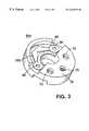
- FIG. 1is a partially cutaway view of a wheel assembly and suspension system according to the invention
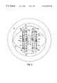
- FIG. 2is a cross sectional view of damping mass assembly according to the invention.
- FIG. 3is a perspective view of an orifice plate according to the invention.
- FIG. 4is a top elevational view of a flapper
- FIG. 5is the orifice plate of FIG. 3 with the flapper of FIG. 4 in position;
- FIGS. 6 a - 6 care side cross sectional views of the orifice plate of FIG. 5, illustrating the operation of the flapper.
- Wheel assembly 10includes an axis defined by axle 37 , tire 12 , hub 14 , and brake elements including brake disk 18 and brake pad 16 .
- mass damper assembly 19Positioned in an annular region which has an outer radius generally defined by the outer extent of brake elements (brake pad 18 and brake disk 16 ), is mass damper assembly 19 .
- Mass damper assembly 19includes damping mass 20 and vertical positioning assembly 24 which includes central shaft 28 disposed in a hollow cylinder 26 in the damping mass 20 , orifice plate 30 , and vertical positioning springs 32 and 34 .
- Actuator 36couples wheel assembly 10 to the body subframe, both shown in this view.
- mass damper assembly 19includes a second vertical positioning assembly, not shown in this view.
- Actuator 36which may be a linear actuator such as described in U.S. Pat. No. 4,981,309, acts to oppose upward and downward motion of the wheel assembly, thereby isolating the body subframe and therefore the passenger compartment of the automobile from vertical motion caused by unevenness in the road. Additionally, actuator 36 may coact with similar actuators on other wheels to control the attitude of the passenger compartment.
- Mass damper assembly 19includes a damping mass 20 and two vertical positioning assemblies 24 a, 24 b, including central shafts 26 a and 26 b, vertical positioning springs 28 a, 30 a, 28 b and 30 b, orifice plates 60 a and 60 b, and fluid filled cylinders 70 a and 70 b.
- Slot 38extends through damping mass 20 in a horizontal direction along an axis parallel to the axis of rotation of the tire to allow axle 14 to move vertically relative to damping mass 20 .
- Hollow cylinders 27 a, 27 bextend vertically through damping mass 20 .
- Shafts 26 a, 26 bare rigidly attached at each end to the non-rotating portion of the wheel.
- Shafts 26 a, 26 bextend vertically through cylinders 27 a, 27 b.
- Orifice plates 60 a, 60 bare rigidly attached to the shaft at a position approximately vertically centered in the damping mass 20 .
- Endcaps 44 a, 44 b, 46 a, 46 bare fixedly attached to damping mass 20 in the ends of cylinders 27 a, 27 b.
- Vertical positioning springs 28 a, 30 a, 28 b and 30 bare that they urge damping mass 20 toward a vertically centered position relative to axle 37 .
- the outside diameter of springs 28 a, 30 a, 28 b, and 30 bis approximately equal to the diameter of cylinders 27 a and 27 b.
- vertical positioning springs 28 a, 30 a, 28 b, and 30 bare not attached at either end to an endplate, to an orifice plate, or to the shaft; that is, the positioning springs are “floating” are not precompressed.
- elements of vertical positioning assemblies 24 a, 24 bmay be dimensioned, constructed, and arranged so that only one of springs 28 a, and 30 b exert force at any one time.
- elements of vertical positioning assemblies 24 a, 24 bmay be dimensioned, constructed, and arranged so that vertical positioning springs 28 a, 30 a, 28 b and 30 b exert force only in compression. This is advantageous because it enables vertical positioning to be performed with shorter springs. Having shorter springs enables the mass damper assembly 19 to be smaller, which in turn allows both brakes and mass damper assembly 19 to be placed in the wheel.
- Sealed portions 70 a and 70 b of cylinders 27 a, 27 b between the endplates 44 a, 46 a and 44 b, 46 bmay contain a fluid, such as hydraulic oil.
- Bearings (not shown) in the endcapspermit damping mass 54 to move up and down relative to shafts 28 a, 28 b, while seals retain fluid in sealed portions 70 a, and 70 b.
- damping mass 20compresses springs 30 a and 30 b, which causes them to exert a downward force on endcaps 46 a and 46 b thereby urging damping mass 20 downwards toward a horizontally centered position. Since the springs are not attached at either end, springs 28 a, 28 b, 30 a, 30 b exert force in compression, but not in tension. Upper springs 28 a and 28 b do not oppose or augment an upward motion of damping mass 20 , and lower springs 30 a and 30 b do not oppose or augment downward motion of damping mass 20 .
- the fluid cylinders 27 a and 27 bacts as a part of damping mass 54 and also resists vertical motion of damping mass 54 relative to shafts 28 a, 28 b, to dissipate vertical vibrational energy.
- a vertical motion of damping mass 54causes fluid to pass through orifices 72 in orifice plates 60 a and 60 b.
- the orificesare sized such that they resist the flow of the fluid, thereby damping the vertical motion of the damping mass.
- Orifice plate 60 a and 60 bare constructed and arranged so that they exert an appropriate resistive force at all motion velocities encountered by the mass damper assembly. The orifices will be discussed below in FIGS. 3-6 c and the corresponding portions of the disclosure.
- a damping mass assemblyhas a damping mass 19 of about one half the mass of the wheel assembly mass, a spring rate of 270 lbs./inch and a tire elasticity of 1600 lbs./inch.
- a damping mass assembly according to the inventionis advantageous because the size of the damping mass assembly may be made small enough, using conventional materials, to permit placing brake elements in the wheel.
- Orifice plate 60 ahas a generally round footprint to fit inside shaft 28 a.
- Orifice platehas two generally round faces, of which one face is shown in this view.
- Orifices 72allow fluid to pass through orifice plate 60 a.
- Two additional orificesare obscured in this view by flapper 80 , which is mounted on face 79 .
- Mounting hole 75is for mounting a flapper (obscured in this view), similar to flapper 80 , on the face opposite face 79 . In operation, mounting hole 75 is occupied by a screw or other fastener (not shown), so there is no fluid flow through mounting hole 75 .
- flapper 80is made of 0.022 inch thick spring steel, and has a central section 84 with a mounting hole 82 which is aligned with orifice plate mounting hole 75 for accommodating a mounting screw or other fastener. Extending from central section 84 are arms 86 , 88 . At the distal ends of arms 86 , 88 are flapping sections 90 , 92 , which may be circular with a radius of about 0.500 inches, slightly larger than orifices 72 of FIG. 3 .
- Flapper 80is positioned such that the central section is fixedly attached to the orifice plate and so that the flapping sections are free to deflect away from the orifice plate as will be further explained below.
- Flapper 80may include a low velocity hole 94 , 96 in each flapping section 90 , 92 which may be concentric with the circular flapper section.
- the low velocity holehas a radius of approximately 0.167 inches.
- FIG. 5there is shown a top plan view of one of the orifice plates 60 a with a flapper 80 in position.
- Central hole 94accommodates shafts 56 a or 56 b.
- Four orifices 72approximately 0.467 inches in diameter allow fluid to pass through orifice plate 60 a.
- Flapper 80is positioned such that sections 90 , 92 cover orifices 72 .
- a second flapper 80(not shown in this view) may be positioned on the opposing face of orifice plate 60 a.
- FIGS. 60-6 cthere are shown partial cross sectional views of orifice plate 60 a illustrating the operation of the flappers 80 .
- fluidflows through central holes 94 as shown in FIG. 6 a, sot hat the effective area of each orifice 72 is the area of the hole 94 .
- force against flapping section 90is sufficient to deflect flapping section 90 away from orifice plate upward as shown in FIG. 6 b, so that the fluid flows not only through central hole 94 , but also through region 98 in which the flapper has been deflected away from orifice plate 60 a, thereby making the effective area of orifice 72 larger.
- force against flapping section 90is sufficient to deflect flapping section 90 sufficiently away from orifice plate 60 a so that the flow is not restricted by flapping section 90 but rather by orifice 72 and the effective area of orifice 72 is essentially equal to the area of the orifice. Additional deflection of flapping section 90 does not increase the effective area of orifice 72 , but may deform flapping section 90 . To prevent excessive deflection of flapping section 90 , stop 100 may be included.
Landscapes
- Engineering & Computer Science (AREA)
- General Engineering & Computer Science (AREA)
- Mechanical Engineering (AREA)
- Physics & Mathematics (AREA)
- Fluid Mechanics (AREA)
- Vehicle Body Suspensions (AREA)
- Fluid-Damping Devices (AREA)
- Vibration Prevention Devices (AREA)
- Braking Arrangements (AREA)
Abstract
Description
Claims (18)
Priority Applications (4)
| Application Number | Priority Date | Filing Date | Title |
|---|---|---|---|
| US09/140,937US6364078B1 (en) | 1998-08-27 | 1998-08-27 | Wheel damping |
| DE69927891TDE69927891T2 (en) | 1998-08-27 | 1999-08-23 | Damped wheel |
| JP23548299AJP4394207B2 (en) | 1998-08-27 | 1999-08-23 | Wheel assembly |
| EP99306674AEP0982162B1 (en) | 1998-08-27 | 1999-08-23 | Wheel damping |
Applications Claiming Priority (1)
| Application Number | Priority Date | Filing Date | Title |
|---|---|---|---|
| US09/140,937US6364078B1 (en) | 1998-08-27 | 1998-08-27 | Wheel damping |
Publications (1)
| Publication Number | Publication Date |
|---|---|
| US6364078B1true US6364078B1 (en) | 2002-04-02 |
Family
ID=22493457
Family Applications (1)
| Application Number | Title | Priority Date | Filing Date |
|---|---|---|---|
| US09/140,937Expired - LifetimeUS6364078B1 (en) | 1998-08-27 | 1998-08-27 | Wheel damping |
Country Status (4)
| Country | Link |
|---|---|
| US (1) | US6364078B1 (en) |
| EP (1) | EP0982162B1 (en) |
| JP (1) | JP4394207B2 (en) |
| DE (1) | DE69927891T2 (en) |
Cited By (42)
| Publication number | Priority date | Publication date | Assignee | Title |
|---|---|---|---|---|
| US20040074720A1 (en)* | 2002-05-07 | 2004-04-22 | Thieltges Gary Peter | Motion stabilized mounts |
| EP1440826A2 (en) | 2003-01-21 | 2004-07-28 | Bose Corporation | Active vehicle suspension system |
| US20050247496A1 (en)* | 2002-08-29 | 2005-11-10 | Go Nagaya | In-wheel motor system |
| US20070068715A1 (en)* | 2003-09-30 | 2007-03-29 | Toyota Jidosha Kabushiki Kaisha | Wheel supporting apparatus improving ride comfort of vehicle |
| US20070107959A1 (en)* | 2003-12-24 | 2007-05-17 | Kabushiki Kaisha Bridgestone | In-wheel motor system |
| US20070144801A1 (en)* | 2003-12-22 | 2007-06-28 | Yasuhiro Suzuki | In-wheel motor system |
| US20070199750A1 (en)* | 2004-04-05 | 2007-08-30 | Yasuhiro Suzuki | In-Wheel Motor System |
| US20080018070A1 (en)* | 2006-07-21 | 2008-01-24 | Gottschalk Michael J | Self-steering axle suspension system having a rotary stabilizer |
| US20080017462A1 (en)* | 2004-05-25 | 2008-01-24 | Toyota Jidosha Kabushiki Kaisha | Wheel Support Device |
| US20080179797A1 (en)* | 2007-01-31 | 2008-07-31 | Hilti Aktiengesellschaft | Oscillation damper for a hand-held power tool |
| US20080185807A1 (en)* | 2005-08-31 | 2008-08-07 | Toyota Jidosha Kabushiki Kaisha | In-Wheel Suspension |
| US20080283314A1 (en)* | 2004-04-05 | 2008-11-20 | Yasuhiro Suzuki | In-Wheel Motor System and Method of Installing the Same |
| US20080283315A1 (en)* | 2004-04-05 | 2008-11-20 | Yasuhiro Suzuki | Vehicle Having In-Wheel Motors |
| CN101132936B (en)* | 2005-08-31 | 2010-05-19 | 丰田自动车株式会社 | In-wheel suspension |
| US20120023881A1 (en)* | 2010-07-30 | 2012-02-02 | Dirk Speckamp | Self-propelled harvesting machine |
| US20130106074A1 (en)* | 2010-07-07 | 2013-05-02 | Ahmet Bugra Koku | Suspension Device for a Vehicle |
| US8579311B2 (en) | 2011-05-12 | 2013-11-12 | GM Global Technology Operations LLC | Wheel mass damper assembly |
| WO2014004118A1 (en) | 2012-06-27 | 2014-01-03 | Bose Corporation | Anti-causal vehicle suspension |
| WO2014004119A1 (en) | 2012-06-27 | 2014-01-03 | Bose Corporation | Active wheel damping |
| US8783430B2 (en) | 2012-06-26 | 2014-07-22 | Bose Corporation | Tuned vibration absorber for active vehicle suspension |
| US9273754B2 (en) | 2012-02-27 | 2016-03-01 | Ford Global Technologies, Llc | Non-uniform axisymmetric driveline/axle damper |
| US10814690B1 (en) | 2017-04-18 | 2020-10-27 | Apple Inc. | Active suspension system with energy storage device |
| US10899340B1 (en) | 2017-06-21 | 2021-01-26 | Apple Inc. | Vehicle with automated subsystems |
| US10906370B1 (en) | 2017-09-15 | 2021-02-02 | Apple Inc. | Active suspension system |
| US10960723B1 (en) | 2017-09-26 | 2021-03-30 | Apple Inc. | Wheel-mounted suspension actuators |
| US11046143B1 (en) | 2015-03-18 | 2021-06-29 | Apple Inc. | Fully-actuated suspension system |
| US11124035B1 (en) | 2017-09-25 | 2021-09-21 | Apple Inc. | Multi-stage active suspension actuator |
| US11173766B1 (en) | 2017-09-07 | 2021-11-16 | Apple Inc. | Suspension system with locking structure |
| US11179991B1 (en) | 2019-09-23 | 2021-11-23 | Apple Inc. | Suspension systems |
| US11267530B2 (en)* | 2017-11-23 | 2022-03-08 | Lg Electronics Inc. | In-wheel motor driving device and movement device including same |
| US11285773B1 (en) | 2018-09-12 | 2022-03-29 | Apple Inc. | Control system |
| US11345209B1 (en) | 2019-06-03 | 2022-05-31 | Apple Inc. | Suspension systems |
| US11358431B2 (en) | 2017-05-08 | 2022-06-14 | Apple Inc. | Active suspension system |
| US11486460B2 (en)* | 2019-08-27 | 2022-11-01 | Deere & Company | Work vehicle with tuned mass dampers |
| US11634167B1 (en) | 2018-09-14 | 2023-04-25 | Apple Inc. | Transmitting axial and rotational movement to a hub |
| US11707961B1 (en) | 2020-04-28 | 2023-07-25 | Apple Inc. | Actuator with reinforcing structure for torsion resistance |
| US11828339B1 (en)* | 2020-07-07 | 2023-11-28 | Apple Inc. | Vibration control system |
| US11938922B1 (en) | 2019-09-23 | 2024-03-26 | Apple Inc. | Motion control system |
| US11981176B2 (en) | 2021-02-10 | 2024-05-14 | Gene Hawkins | Active suspension control system for a motor vehicle |
| US12017498B2 (en) | 2021-06-07 | 2024-06-25 | Apple Inc. | Mass damper system |
| US12168375B1 (en) | 2023-01-26 | 2024-12-17 | Apple Inc. | Motion control system |
| US12251973B2 (en) | 2022-06-10 | 2025-03-18 | Apple Inc. | Vibration absorber |
Families Citing this family (13)
| Publication number | Priority date | Publication date | Assignee | Title |
|---|---|---|---|---|
| JP2003039902A (en)* | 2001-07-30 | 2003-02-13 | Kayaba Ind Co Ltd | Wheel with built-in suspension |
| JP4666831B2 (en)* | 2001-07-30 | 2011-04-06 | カヤバ工業株式会社 | Suspension built-in wheel |
| JP4113506B2 (en)* | 2003-09-30 | 2008-07-09 | トヨタ自動車株式会社 | Wheel support device |
| JP2005313815A (en)* | 2004-04-30 | 2005-11-10 | Topy Ind Ltd | Wheel assembly |
| US7427072B2 (en)* | 2004-06-18 | 2008-09-23 | Bose Corporation | Active vehicle suspension |
| US7823891B2 (en)* | 2005-11-29 | 2010-11-02 | Bose Corporation | Active vehicle suspension system |
| US7810818B2 (en) | 2005-11-29 | 2010-10-12 | Dariusz Antoni Bushko | Active vehicle suspension system |
| JP4595803B2 (en)* | 2005-12-16 | 2010-12-08 | トヨタ自動車株式会社 | In-wheel suspension structure |
| DE102009047100B4 (en) | 2009-11-25 | 2019-09-05 | Robert Bosch Gmbh | Suspension for a vehicle |
| DE102009047102A1 (en) | 2009-11-25 | 2011-05-26 | Robert Bosch Gmbh | Chassis frame for vehicle, comprises power transmission device between opposite lying wheel suspensions on vehicle axis, where actuator is attached to power transmission device for adjustment of power |
| DE102009047144B4 (en) | 2009-11-25 | 2020-03-12 | Robert Bosch Gmbh | Wheel suspension for a vehicle |
| CH709846A2 (en)* | 2014-07-03 | 2016-01-15 | Duss Evolution Gmbh | Axial suspension and damping system for a wheel of a single- or multi-track vehicle. |
| CN105365550A (en)* | 2015-11-24 | 2016-03-02 | 苏州先锋物流装备科技有限公司 | Horizontal drive assembly with shock absorption function |
Citations (8)
| Publication number | Priority date | Publication date | Assignee | Title |
|---|---|---|---|---|
| US2854100A (en) | 1954-11-15 | 1958-09-30 | Gen Motors Corp | Vibration damper |
| US2955841A (en) | 1956-05-31 | 1960-10-11 | Gen Motors Corp | Wheel hop damper |
| DE1117417B (en) | 1960-03-25 | 1961-11-16 | Daimler Benz Ag | Dynamic vibration damper, especially for motor vehicles |
| US4442925A (en)* | 1980-09-12 | 1984-04-17 | Nissan Motor Co., Ltd. | Vortex flow hydraulic shock absorber |
| DE4004333A1 (en) | 1989-03-08 | 1990-09-13 | Volkswagen Ag | VIBRATION DETECTOR FOR MOTOR VEHICLE WHEELS |
| US4981309A (en)* | 1989-08-31 | 1991-01-01 | Bose Corporation | Electromechanical transducing along a path |
| US4991698A (en)* | 1988-05-16 | 1991-02-12 | Bose Corporation | Damping with damping mass inside wheel |
| US5829556A (en)* | 1994-11-14 | 1998-11-03 | Jarret | Damper device, of the type with hydrostatic compression of elastomer, and its applications |
- 1998
- 1998-08-27USUS09/140,937patent/US6364078B1/ennot_activeExpired - Lifetime
- 1999
- 1999-08-23DEDE69927891Tpatent/DE69927891T2/ennot_activeExpired - Lifetime
- 1999-08-23JPJP23548299Apatent/JP4394207B2/ennot_activeExpired - Fee Related
- 1999-08-23EPEP99306674Apatent/EP0982162B1/ennot_activeExpired - Lifetime
Patent Citations (8)
| Publication number | Priority date | Publication date | Assignee | Title |
|---|---|---|---|---|
| US2854100A (en) | 1954-11-15 | 1958-09-30 | Gen Motors Corp | Vibration damper |
| US2955841A (en) | 1956-05-31 | 1960-10-11 | Gen Motors Corp | Wheel hop damper |
| DE1117417B (en) | 1960-03-25 | 1961-11-16 | Daimler Benz Ag | Dynamic vibration damper, especially for motor vehicles |
| US4442925A (en)* | 1980-09-12 | 1984-04-17 | Nissan Motor Co., Ltd. | Vortex flow hydraulic shock absorber |
| US4991698A (en)* | 1988-05-16 | 1991-02-12 | Bose Corporation | Damping with damping mass inside wheel |
| DE4004333A1 (en) | 1989-03-08 | 1990-09-13 | Volkswagen Ag | VIBRATION DETECTOR FOR MOTOR VEHICLE WHEELS |
| US4981309A (en)* | 1989-08-31 | 1991-01-01 | Bose Corporation | Electromechanical transducing along a path |
| US5829556A (en)* | 1994-11-14 | 1998-11-03 | Jarret | Damper device, of the type with hydrostatic compression of elastomer, and its applications |
Cited By (72)
| Publication number | Priority date | Publication date | Assignee | Title |
|---|---|---|---|---|
| US20040074720A1 (en)* | 2002-05-07 | 2004-04-22 | Thieltges Gary Peter | Motion stabilized mounts |
| US7287611B2 (en)* | 2002-08-29 | 2007-10-30 | Kabushiki Kaisha Bridgestone | In-wheel motor system |
| US20050247496A1 (en)* | 2002-08-29 | 2005-11-10 | Go Nagaya | In-wheel motor system |
| EP1440826A2 (en) | 2003-01-21 | 2004-07-28 | Bose Corporation | Active vehicle suspension system |
| EP2233330A2 (en) | 2003-01-21 | 2010-09-29 | Bose Corporation | Active suspension system for vehicle |
| EP2233331A2 (en) | 2003-01-21 | 2010-09-29 | Bose Corporation | Active suspension sytem for a vehicle |
| US7703780B2 (en) | 2003-09-30 | 2010-04-27 | Toyota Jidosha Kabushiki Kaisha | Wheel supporting apparatus improving ride comfort of vehicle |
| US20070068715A1 (en)* | 2003-09-30 | 2007-03-29 | Toyota Jidosha Kabushiki Kaisha | Wheel supporting apparatus improving ride comfort of vehicle |
| US20070144801A1 (en)* | 2003-12-22 | 2007-06-28 | Yasuhiro Suzuki | In-wheel motor system |
| US7552786B2 (en)* | 2003-12-22 | 2009-06-30 | Kabushiki Kaisha Bridgestone | In-wheel motor system |
| US20070107959A1 (en)* | 2003-12-24 | 2007-05-17 | Kabushiki Kaisha Bridgestone | In-wheel motor system |
| US7422080B2 (en)* | 2003-12-24 | 2008-09-09 | Kabushiki Kaisha Bridgestone | In-wheel motor system |
| US20070199750A1 (en)* | 2004-04-05 | 2007-08-30 | Yasuhiro Suzuki | In-Wheel Motor System |
| US7766110B2 (en)* | 2004-04-05 | 2010-08-03 | Kabushiki Kaisha Bridgestone | Vehicle having in-wheel motors |
| US7621357B2 (en)* | 2004-04-05 | 2009-11-24 | Kabushiki Kaisha Bridgestone | In-wheel motor system and method of installing the same |
| US20080283314A1 (en)* | 2004-04-05 | 2008-11-20 | Yasuhiro Suzuki | In-Wheel Motor System and Method of Installing the Same |
| US20080283315A1 (en)* | 2004-04-05 | 2008-11-20 | Yasuhiro Suzuki | Vehicle Having In-Wheel Motors |
| US7556112B2 (en)* | 2004-04-05 | 2009-07-07 | Kabushiki Kaisha Bridgestone | In-wheel motor system |
| US7789178B2 (en)* | 2004-05-25 | 2010-09-07 | Toyota Jidosha Kabushiki Kaisha | Wheel support device |
| US20080017462A1 (en)* | 2004-05-25 | 2008-01-24 | Toyota Jidosha Kabushiki Kaisha | Wheel Support Device |
| CN101132936B (en)* | 2005-08-31 | 2010-05-19 | 丰田自动车株式会社 | In-wheel suspension |
| US7770677B2 (en)* | 2005-08-31 | 2010-08-10 | Toyota Jidosha Kabushiki Kaisha | In-wheel suspension |
| US20080185807A1 (en)* | 2005-08-31 | 2008-08-07 | Toyota Jidosha Kabushiki Kaisha | In-Wheel Suspension |
| US7748724B2 (en) | 2006-07-21 | 2010-07-06 | Hendrickson Usa, L.L.C. | Self-steering axle suspension system having a rotary stabilizer |
| US7360773B2 (en) | 2006-07-21 | 2008-04-22 | Hendrickson Usa, L.L.C. | Self-steering axle suspension system having a rotary stabilizer |
| US20080018070A1 (en)* | 2006-07-21 | 2008-01-24 | Gottschalk Michael J | Self-steering axle suspension system having a rotary stabilizer |
| US20080179797A1 (en)* | 2007-01-31 | 2008-07-31 | Hilti Aktiengesellschaft | Oscillation damper for a hand-held power tool |
| US8356702B2 (en)* | 2007-01-31 | 2013-01-22 | Hilti Aktiengesellschaft | Oscillation damper for a hand-held power tool |
| US20130106074A1 (en)* | 2010-07-07 | 2013-05-02 | Ahmet Bugra Koku | Suspension Device for a Vehicle |
| US9156323B2 (en)* | 2010-07-07 | 2015-10-13 | Ahmet Bugra Koku | Suspension device for a vehicle |
| US20120023881A1 (en)* | 2010-07-30 | 2012-02-02 | Dirk Speckamp | Self-propelled harvesting machine |
| US8341926B2 (en)* | 2010-07-30 | 2013-01-01 | Claas Selbstfahrende Erntemaschinen Gmbh | Self-propelled harvesting machine with hydropneumatic dampening system |
| US8579311B2 (en) | 2011-05-12 | 2013-11-12 | GM Global Technology Operations LLC | Wheel mass damper assembly |
| US9273754B2 (en) | 2012-02-27 | 2016-03-01 | Ford Global Technologies, Llc | Non-uniform axisymmetric driveline/axle damper |
| US8783430B2 (en) | 2012-06-26 | 2014-07-22 | Bose Corporation | Tuned vibration absorber for active vehicle suspension |
| US8938333B2 (en) | 2012-06-27 | 2015-01-20 | Bose Corporation | Active wheel damping |
| US9102209B2 (en) | 2012-06-27 | 2015-08-11 | Bose Corporation | Anti-causal vehicle suspension |
| WO2014004119A1 (en) | 2012-06-27 | 2014-01-03 | Bose Corporation | Active wheel damping |
| WO2014004118A1 (en) | 2012-06-27 | 2014-01-03 | Bose Corporation | Anti-causal vehicle suspension |
| EP3424758A2 (en) | 2012-06-27 | 2019-01-09 | ClearMotion Acquisition l LLC | Active wheel damping |
| US11046143B1 (en) | 2015-03-18 | 2021-06-29 | Apple Inc. | Fully-actuated suspension system |
| US11945279B1 (en) | 2015-03-18 | 2024-04-02 | Apple Inc. | Motion control system |
| US10814690B1 (en) | 2017-04-18 | 2020-10-27 | Apple Inc. | Active suspension system with energy storage device |
| US11358431B2 (en) | 2017-05-08 | 2022-06-14 | Apple Inc. | Active suspension system |
| US11701942B2 (en) | 2017-05-08 | 2023-07-18 | Apple Inc. | Motion control system |
| US12115827B2 (en) | 2017-05-08 | 2024-10-15 | Apple Inc. | Motion control system |
| US10899340B1 (en) | 2017-06-21 | 2021-01-26 | Apple Inc. | Vehicle with automated subsystems |
| US11702065B1 (en) | 2017-06-21 | 2023-07-18 | Apple Inc. | Thermal management system control |
| US11173766B1 (en) | 2017-09-07 | 2021-11-16 | Apple Inc. | Suspension system with locking structure |
| US10906370B1 (en) | 2017-09-15 | 2021-02-02 | Apple Inc. | Active suspension system |
| US11065931B1 (en) | 2017-09-15 | 2021-07-20 | Apple Inc. | Active suspension system |
| US11124035B1 (en) | 2017-09-25 | 2021-09-21 | Apple Inc. | Multi-stage active suspension actuator |
| US12043073B1 (en) | 2017-09-25 | 2024-07-23 | Apple Inc. | Multi-stage active suspension actuator |
| US10960723B1 (en) | 2017-09-26 | 2021-03-30 | Apple Inc. | Wheel-mounted suspension actuators |
| US11267530B2 (en)* | 2017-11-23 | 2022-03-08 | Lg Electronics Inc. | In-wheel motor driving device and movement device including same |
| US12097740B1 (en) | 2018-09-12 | 2024-09-24 | Apple Inc. | Control system |
| US11285773B1 (en) | 2018-09-12 | 2022-03-29 | Apple Inc. | Control system |
| US11634167B1 (en) | 2018-09-14 | 2023-04-25 | Apple Inc. | Transmitting axial and rotational movement to a hub |
| US11345209B1 (en) | 2019-06-03 | 2022-05-31 | Apple Inc. | Suspension systems |
| US12054028B1 (en) | 2019-06-03 | 2024-08-06 | Apple Inc. | Motion control systems |
| US11486460B2 (en)* | 2019-08-27 | 2022-11-01 | Deere & Company | Work vehicle with tuned mass dampers |
| US11179991B1 (en) | 2019-09-23 | 2021-11-23 | Apple Inc. | Suspension systems |
| US11938922B1 (en) | 2019-09-23 | 2024-03-26 | Apple Inc. | Motion control system |
| US11731476B1 (en) | 2019-09-23 | 2023-08-22 | Apple Inc. | Motion control systems |
| US12134292B1 (en) | 2019-09-23 | 2024-11-05 | Apple Inc. | Motion control systems |
| US11707961B1 (en) | 2020-04-28 | 2023-07-25 | Apple Inc. | Actuator with reinforcing structure for torsion resistance |
| US11828339B1 (en)* | 2020-07-07 | 2023-11-28 | Apple Inc. | Vibration control system |
| US12215747B1 (en)* | 2020-07-07 | 2025-02-04 | Apple Inc. | Vibration control system |
| US11981176B2 (en) | 2021-02-10 | 2024-05-14 | Gene Hawkins | Active suspension control system for a motor vehicle |
| US12017498B2 (en) | 2021-06-07 | 2024-06-25 | Apple Inc. | Mass damper system |
| US12251973B2 (en) | 2022-06-10 | 2025-03-18 | Apple Inc. | Vibration absorber |
| US12168375B1 (en) | 2023-01-26 | 2024-12-17 | Apple Inc. | Motion control system |
Also Published As
| Publication number | Publication date |
|---|---|
| DE69927891D1 (en) | 2005-12-01 |
| JP2000074134A (en) | 2000-03-07 |
| JP4394207B2 (en) | 2010-01-06 |
| EP0982162B1 (en) | 2005-10-26 |
| EP0982162A3 (en) | 2000-12-06 |
| EP0982162A2 (en) | 2000-03-01 |
| DE69927891T2 (en) | 2006-04-20 |
Similar Documents
| Publication | Publication Date | Title |
|---|---|---|
| US6364078B1 (en) | Wheel damping | |
| US4991698A (en) | Damping with damping mass inside wheel | |
| US5263694A (en) | Upper mount assembly for a suspension damper | |
| JP3148219B2 (en) | Suspension device | |
| JP3499566B2 (en) | Suspension system | |
| JP4455270B2 (en) | damper | |
| JP2795413B2 (en) | Braking valve for air spring suspension system | |
| US4804169A (en) | Composite jounce bumper for vehicle suspension strut | |
| US4624347A (en) | Piston assembly for shock absorber | |
| CA1050344A (en) | Railway car truck | |
| US4615420A (en) | Piston assembly for shock absorber | |
| JPH07505697A (en) | surface effect damper | |
| JP3022913B2 (en) | Wheel damper | |
| US5150886A (en) | Top mount assembly for a suspension actuator | |
| US20090200718A1 (en) | Spring Shock Absorber for a Motor Vehicle | |
| EP0039133A1 (en) | Vehicular strut type suspension systems | |
| JP3084544B2 (en) | Liquid-filled mounting device | |
| JP3999499B2 (en) | Suspension device | |
| KR20200128921A (en) | Shock absorber for vehicle | |
| JP2006518296A (en) | Vibration absorption mechanism for wheels running on tires filled with air | |
| US4688777A (en) | Pair of stacked springs for a railway car | |
| US4767134A (en) | Vehicle suspension system with multiple overlapping composite control arm elements | |
| JPS6165930A (en) | Fluid pressure damping unit | |
| US5186439A (en) | Friction compensating automotive suspension strut | |
| JPS6240191Y2 (en) |
Legal Events
| Date | Code | Title | Description |
|---|---|---|---|
| AS | Assignment | Owner name:BOSE CORPORATION, MASSACHUSETTS Free format text:ASSIGNMENT OF ASSIGNORS INTEREST;ASSIGNORS:PARISON, JAMES A.;KNOX, LAWRENCE D.;REEL/FRAME:009416/0491 Effective date:19980826 | |
| STCF | Information on status: patent grant | Free format text:PATENTED CASE | |
| FPAY | Fee payment | Year of fee payment:4 | |
| FEPP | Fee payment procedure | Free format text:PAYOR NUMBER ASSIGNED (ORIGINAL EVENT CODE: ASPN); ENTITY STATUS OF PATENT OWNER: LARGE ENTITY | |
| FPAY | Fee payment | Year of fee payment:8 | |
| FPAY | Fee payment | Year of fee payment:12 | |
| AS | Assignment | Owner name:CLEARMOTION ACQUISITION I LLC, MASSACHUSETTS Free format text:NUNC PRO TUNC ASSIGNMENT;ASSIGNOR:BOSE CORPORATION;REEL/FRAME:044980/0060 Effective date:20171214 | |
| AS | Assignment | Owner name:FRANKLIN STRATEGIC SERIES - FRANKLIN SMALL CAP GROWTH FUND, CALIFORNIA Free format text:PATENT SECURITY AGREEMENT;ASSIGNOR:CLEARMOTION, INC.;REEL/FRAME:058644/0007 Effective date:20211221 Owner name:FRANKLIN TEMPLETON INVESTMENT FUNDS - FRANKLIN U.S. OPPORTUNITIES FUND, CALIFORNIA Free format text:PATENT SECURITY AGREEMENT;ASSIGNOR:CLEARMOTION, INC.;REEL/FRAME:058644/0007 Effective date:20211221 Owner name:FRANKLIN STRATEGIC SERIES - FRANKLIN GROWTH OPPORTUNITIES FUND, CALIFORNIA Free format text:PATENT SECURITY AGREEMENT;ASSIGNOR:CLEARMOTION, INC.;REEL/FRAME:058644/0007 Effective date:20211221 Owner name:WIL FUND I, L.P., CALIFORNIA Free format text:PATENT SECURITY AGREEMENT;ASSIGNOR:CLEARMOTION, INC.;REEL/FRAME:058644/0007 Effective date:20211221 Owner name:ACADIA WOODS PARTNERS, LLC, NEW YORK Free format text:PATENT SECURITY AGREEMENT;ASSIGNOR:CLEARMOTION, INC.;REEL/FRAME:058644/0007 Effective date:20211221 Owner name:NEWVIEW CAPITAL FUND I, L.P., CALIFORNIA Free format text:PATENT SECURITY AGREEMENT;ASSIGNOR:CLEARMOTION, INC.;REEL/FRAME:058644/0007 Effective date:20211221 | |
| AS | Assignment | Owner name:ACADIA WOODS PARTNERS, LLC, NEW YORK Free format text:AMENDED & RESTATED PATENT SECURITY AGREEMENT;ASSIGNORS:CLEARMOTION, INC.;CLEARMOTION ACQUISITION I LLC;REEL/FRAME:059361/0433 Effective date:20220310 | |
| AS | Assignment | Owner name:BRILLIANCE JOURNEY LIMITED, VIRGIN ISLANDS, BRITISH Free format text:CORRECTIVE ASSIGNMENT TO CORRECT THE ADDING ASSIGNEE PREVIOUSLY RECORDED AT REEL: 059361 FRAME: 0433. ASSIGNOR(S) HEREBY CONFIRMS THE SECURITY AGREEMENT;ASSIGNORS:CLEARMOTION, INC.;CLEARMOTION ACQUISITION I LLC;REEL/FRAME:060130/0001 Effective date:20220310 Owner name:THE PRIVATE SHARES FUND, CALIFORNIA Free format text:CORRECTIVE ASSIGNMENT TO CORRECT THE ADDING ASSIGNEE PREVIOUSLY RECORDED AT REEL: 059361 FRAME: 0433. ASSIGNOR(S) HEREBY CONFIRMS THE SECURITY AGREEMENT;ASSIGNORS:CLEARMOTION, INC.;CLEARMOTION ACQUISITION I LLC;REEL/FRAME:060130/0001 Effective date:20220310 Owner name:TEW LIMITED PARTNERSHIP, MARYLAND Free format text:CORRECTIVE ASSIGNMENT TO CORRECT THE ADDING ASSIGNEE PREVIOUSLY RECORDED AT REEL: 059361 FRAME: 0433. ASSIGNOR(S) HEREBY CONFIRMS THE SECURITY AGREEMENT;ASSIGNORS:CLEARMOTION, INC.;CLEARMOTION ACQUISITION I LLC;REEL/FRAME:060130/0001 Effective date:20220310 Owner name:FHW LIMITED PARTNERSHIP, MARYLAND Free format text:CORRECTIVE ASSIGNMENT TO CORRECT THE ADDING ASSIGNEE PREVIOUSLY RECORDED AT REEL: 059361 FRAME: 0433. ASSIGNOR(S) HEREBY CONFIRMS THE SECURITY AGREEMENT;ASSIGNORS:CLEARMOTION, INC.;CLEARMOTION ACQUISITION I LLC;REEL/FRAME:060130/0001 Effective date:20220310 Owner name:MICROSOFT GLOBAL FINANCE, WASHINGTON Free format text:CORRECTIVE ASSIGNMENT TO CORRECT THE ADDING ASSIGNEE PREVIOUSLY RECORDED AT REEL: 059361 FRAME: 0433. ASSIGNOR(S) HEREBY CONFIRMS THE SECURITY AGREEMENT;ASSIGNORS:CLEARMOTION, INC.;CLEARMOTION ACQUISITION I LLC;REEL/FRAME:060130/0001 Effective date:20220310 Owner name:BRIDGESTONE AMERICAS, INC., TENNESSEE Free format text:CORRECTIVE ASSIGNMENT TO CORRECT THE ADDING ASSIGNEE PREVIOUSLY RECORDED AT REEL: 059361 FRAME: 0433. ASSIGNOR(S) HEREBY CONFIRMS THE SECURITY AGREEMENT;ASSIGNORS:CLEARMOTION, INC.;CLEARMOTION ACQUISITION I LLC;REEL/FRAME:060130/0001 Effective date:20220310 Owner name:WIL FUND I, L.P., CALIFORNIA Free format text:CORRECTIVE ASSIGNMENT TO CORRECT THE ADDING ASSIGNEE PREVIOUSLY RECORDED AT REEL: 059361 FRAME: 0433. ASSIGNOR(S) HEREBY CONFIRMS THE SECURITY AGREEMENT;ASSIGNORS:CLEARMOTION, INC.;CLEARMOTION ACQUISITION I LLC;REEL/FRAME:060130/0001 Effective date:20220310 Owner name:NEWVIEW CAPITAL FUND I, LP, CALIFORNIA Free format text:CORRECTIVE ASSIGNMENT TO CORRECT THE ADDING ASSIGNEE PREVIOUSLY RECORDED AT REEL: 059361 FRAME: 0433. ASSIGNOR(S) HEREBY CONFIRMS THE SECURITY AGREEMENT;ASSIGNORS:CLEARMOTION, INC.;CLEARMOTION ACQUISITION I LLC;REEL/FRAME:060130/0001 Effective date:20220310 Owner name:FRANKLIN STRATEGIC SERIES - FRANKLIN SMALL CAP GROWTH FUND, CALIFORNIA Free format text:CORRECTIVE ASSIGNMENT TO CORRECT THE ADDING ASSIGNEE PREVIOUSLY RECORDED AT REEL: 059361 FRAME: 0433. ASSIGNOR(S) HEREBY CONFIRMS THE SECURITY AGREEMENT;ASSIGNORS:CLEARMOTION, INC.;CLEARMOTION ACQUISITION I LLC;REEL/FRAME:060130/0001 Effective date:20220310 Owner name:FRANKLIN TEMPLETON INVESTMENT FUNDS - FRANKLIN U.S. OPPORTUNITIES FUND, CALIFORNIA Free format text:CORRECTIVE ASSIGNMENT TO CORRECT THE ADDING ASSIGNEE PREVIOUSLY RECORDED AT REEL: 059361 FRAME: 0433. ASSIGNOR(S) HEREBY CONFIRMS THE SECURITY AGREEMENT;ASSIGNORS:CLEARMOTION, INC.;CLEARMOTION ACQUISITION I LLC;REEL/FRAME:060130/0001 Effective date:20220310 Owner name:FRANKLIN STRATEGIC SERIES - FRANKLIN GROWTH OPPORTUNITIES FUND, CALIFORNIA Free format text:CORRECTIVE ASSIGNMENT TO CORRECT THE ADDING ASSIGNEE PREVIOUSLY RECORDED AT REEL: 059361 FRAME: 0433. ASSIGNOR(S) HEREBY CONFIRMS THE SECURITY AGREEMENT;ASSIGNORS:CLEARMOTION, INC.;CLEARMOTION ACQUISITION I LLC;REEL/FRAME:060130/0001 Effective date:20220310 Owner name:ACADIA WOODS PARTNERS, LLC, NEW YORK Free format text:CORRECTIVE ASSIGNMENT TO CORRECT THE ADDING ASSIGNEE PREVIOUSLY RECORDED AT REEL: 059361 FRAME: 0433. ASSIGNOR(S) HEREBY CONFIRMS THE SECURITY AGREEMENT;ASSIGNORS:CLEARMOTION, INC.;CLEARMOTION ACQUISITION I LLC;REEL/FRAME:060130/0001 Effective date:20220310 | |
| AS | Assignment | Owner name:CLEARMOTION ACQUISITION I LLC, MASSACHUSETTS Free format text:TERMINATION OF AMENDED & RESTATED PATENT SECURITY AGREEMENT;ASSIGNOR:ACADIA WOODS PARTNERS, LLC;REEL/FRAME:062687/0713 Effective date:20220906 Owner name:CLEARMOTION, INC., MASSACHUSETTS Free format text:TERMINATION OF AMENDED & RESTATED PATENT SECURITY AGREEMENT;ASSIGNOR:ACADIA WOODS PARTNERS, LLC;REEL/FRAME:062687/0713 Effective date:20220906 | |
| AS | Assignment | Owner name:CLEARMOTION ACQUISITION I LLC, MASSACHUSETTS Free format text:TERMINATION OF AMENDED & RESTATED PATENT SECURITY AGREEMENT;ASSIGNORS:FRANKLIN STRATEGIC SERIES - FRANKLIN GROWTH OPPORTUNITIES FUND ;FRANKLIN STRATEGIC SERIES - FRANKLIN SMALL CAP GROWTH FUND ;FRANKLIN TEMPLETON INVESTMENT FUNDS - FRANKLIN U.S. OPPORTUNITIES FUND ;AND OTHERS;REEL/FRAME:062705/0684 Effective date:20220906 Owner name:CLEARMOTION, INC., MASSACHUSETTS Free format text:TERMINATION OF AMENDED & RESTATED PATENT SECURITY AGREEMENT;ASSIGNORS:FRANKLIN STRATEGIC SERIES - FRANKLIN GROWTH OPPORTUNITIES FUND ;FRANKLIN STRATEGIC SERIES - FRANKLIN SMALL CAP GROWTH FUND ;FRANKLIN TEMPLETON INVESTMENT FUNDS - FRANKLIN U.S. OPPORTUNITIES FUND ;AND OTHERS;REEL/FRAME:062705/0684 Effective date:20220906 |