US6363940B1 - System and method for bracketing and removing tissue - Google Patents
System and method for bracketing and removing tissueDownload PDFInfo
- Publication number
- US6363940B1 US6363940B1US09/078,982US7898298AUS6363940B1US 6363940 B1US6363940 B1US 6363940B1US 7898298 AUS7898298 AUS 7898298AUS 6363940 B1US6363940 B1US 6363940B1
- Authority
- US
- United States
- Prior art keywords
- marker
- tissue
- markers
- tissue volume
- probe
- Prior art date
- Legal status (The legal status is an assumption and is not a legal conclusion. Google has not performed a legal analysis and makes no representation as to the accuracy of the status listed.)
- Expired - Lifetime
Links
Images


Classifications
- A—HUMAN NECESSITIES
- A61—MEDICAL OR VETERINARY SCIENCE; HYGIENE
- A61B—DIAGNOSIS; SURGERY; IDENTIFICATION
- A61B17/00—Surgical instruments, devices or methods
- A61B17/32—Surgical cutting instruments
- A61B17/3205—Excision instruments
- A61B17/32053—Punch like cutting instruments, e.g. using a cylindrical or oval knife
- A—HUMAN NECESSITIES
- A61—MEDICAL OR VETERINARY SCIENCE; HYGIENE
- A61B—DIAGNOSIS; SURGERY; IDENTIFICATION
- A61B90/00—Instruments, implements or accessories specially adapted for surgery or diagnosis and not covered by any of the groups A61B1/00 - A61B50/00, e.g. for luxation treatment or for protecting wound edges
- A61B90/39—Markers, e.g. radio-opaque or breast lesions markers
- A—HUMAN NECESSITIES
- A61—MEDICAL OR VETERINARY SCIENCE; HYGIENE
- A61B—DIAGNOSIS; SURGERY; IDENTIFICATION
- A61B17/00—Surgical instruments, devices or methods
- A61B17/32—Surgical cutting instruments
- A61B17/3201—Scissors
- A—HUMAN NECESSITIES
- A61—MEDICAL OR VETERINARY SCIENCE; HYGIENE
- A61B—DIAGNOSIS; SURGERY; IDENTIFICATION
- A61B17/00—Surgical instruments, devices or methods
- A61B17/32—Surgical cutting instruments
- A61B17/3209—Incision instruments
- A61B17/3211—Surgical scalpels, knives; Accessories therefor
- A—HUMAN NECESSITIES
- A61—MEDICAL OR VETERINARY SCIENCE; HYGIENE
- A61B—DIAGNOSIS; SURGERY; IDENTIFICATION
- A61B17/00—Surgical instruments, devices or methods
- A61B17/34—Trocars; Puncturing needles
- A61B17/3403—Needle locating or guiding means
- A—HUMAN NECESSITIES
- A61—MEDICAL OR VETERINARY SCIENCE; HYGIENE
- A61B—DIAGNOSIS; SURGERY; IDENTIFICATION
- A61B17/00—Surgical instruments, devices or methods
- A61B17/00234—Surgical instruments, devices or methods for minimally invasive surgery
- A61B2017/00349—Needle-like instruments having hook or barb-like gripping means, e.g. for grasping suture or tissue
- A—HUMAN NECESSITIES
- A61—MEDICAL OR VETERINARY SCIENCE; HYGIENE
- A61B—DIAGNOSIS; SURGERY; IDENTIFICATION
- A61B17/00—Surgical instruments, devices or methods
- A61B17/32—Surgical cutting instruments
- A61B2017/320064—Surgical cutting instruments with tissue or sample retaining means
- A—HUMAN NECESSITIES
- A61—MEDICAL OR VETERINARY SCIENCE; HYGIENE
- A61B—DIAGNOSIS; SURGERY; IDENTIFICATION
- A61B17/00—Surgical instruments, devices or methods
- A61B17/34—Trocars; Puncturing needles
- A61B17/3403—Needle locating or guiding means
- A61B2017/3413—Needle locating or guiding means guided by ultrasound
- A—HUMAN NECESSITIES
- A61—MEDICAL OR VETERINARY SCIENCE; HYGIENE
- A61B—DIAGNOSIS; SURGERY; IDENTIFICATION
- A61B34/00—Computer-aided surgery; Manipulators or robots specially adapted for use in surgery
- A61B34/20—Surgical navigation systems; Devices for tracking or guiding surgical instruments, e.g. for frameless stereotaxis
- A61B2034/2046—Tracking techniques
- A61B2034/2063—Acoustic tracking systems, e.g. using ultrasound
- A—HUMAN NECESSITIES
- A61—MEDICAL OR VETERINARY SCIENCE; HYGIENE
- A61B—DIAGNOSIS; SURGERY; IDENTIFICATION
- A61B90/00—Instruments, implements or accessories specially adapted for surgery or diagnosis and not covered by any of the groups A61B1/00 - A61B50/00, e.g. for luxation treatment or for protecting wound edges
- A61B90/39—Markers, e.g. radio-opaque or breast lesions markers
- A61B2090/3904—Markers, e.g. radio-opaque or breast lesions markers specially adapted for marking specified tissue
- A61B2090/3908—Soft tissue, e.g. breast tissue
- A—HUMAN NECESSITIES
- A61—MEDICAL OR VETERINARY SCIENCE; HYGIENE
- A61B—DIAGNOSIS; SURGERY; IDENTIFICATION
- A61B90/00—Instruments, implements or accessories specially adapted for surgery or diagnosis and not covered by any of the groups A61B1/00 - A61B50/00, e.g. for luxation treatment or for protecting wound edges
- A61B90/39—Markers, e.g. radio-opaque or breast lesions markers
- A61B2090/392—Radioactive markers
- A—HUMAN NECESSITIES
- A61—MEDICAL OR VETERINARY SCIENCE; HYGIENE
- A61B—DIAGNOSIS; SURGERY; IDENTIFICATION
- A61B90/00—Instruments, implements or accessories specially adapted for surgery or diagnosis and not covered by any of the groups A61B1/00 - A61B50/00, e.g. for luxation treatment or for protecting wound edges
- A61B90/39—Markers, e.g. radio-opaque or breast lesions markers
- A61B2090/3925—Markers, e.g. radio-opaque or breast lesions markers ultrasonic
- A61B2090/3929—Active markers
- A—HUMAN NECESSITIES
- A61—MEDICAL OR VETERINARY SCIENCE; HYGIENE
- A61B—DIAGNOSIS; SURGERY; IDENTIFICATION
- A61B90/00—Instruments, implements or accessories specially adapted for surgery or diagnosis and not covered by any of the groups A61B1/00 - A61B50/00, e.g. for luxation treatment or for protecting wound edges
- A61B90/39—Markers, e.g. radio-opaque or breast lesions markers
- A61B2090/3937—Visible markers
- A61B2090/395—Visible markers with marking agent for marking skin or other tissue
- A—HUMAN NECESSITIES
- A61—MEDICAL OR VETERINARY SCIENCE; HYGIENE
- A61B—DIAGNOSIS; SURGERY; IDENTIFICATION
- A61B90/00—Instruments, implements or accessories specially adapted for surgery or diagnosis and not covered by any of the groups A61B1/00 - A61B50/00, e.g. for luxation treatment or for protecting wound edges
- A61B90/39—Markers, e.g. radio-opaque or breast lesions markers
- A61B2090/3954—Markers, e.g. radio-opaque or breast lesions markers magnetic, e.g. NMR or MRI
- A61B2090/3958—Markers, e.g. radio-opaque or breast lesions markers magnetic, e.g. NMR or MRI emitting a signal
- A—HUMAN NECESSITIES
- A61—MEDICAL OR VETERINARY SCIENCE; HYGIENE
- A61B—DIAGNOSIS; SURGERY; IDENTIFICATION
- A61B90/00—Instruments, implements or accessories specially adapted for surgery or diagnosis and not covered by any of the groups A61B1/00 - A61B50/00, e.g. for luxation treatment or for protecting wound edges
- A61B90/39—Markers, e.g. radio-opaque or breast lesions markers
- A61B2090/3995—Multi-modality markers
- A—HUMAN NECESSITIES
- A61—MEDICAL OR VETERINARY SCIENCE; HYGIENE
- A61B—DIAGNOSIS; SURGERY; IDENTIFICATION
- A61B34/00—Computer-aided surgery; Manipulators or robots specially adapted for use in surgery
- A61B34/20—Surgical navigation systems; Devices for tracking or guiding surgical instruments, e.g. for frameless stereotaxis
Definitions
- the present inventionrelates to a system for and method of bracketing a tissue volume containing a tissue mass, e.g., a non-palpable breast tumor, using markers to define the boundary of the tissue volume and a probe and detector to locate the markers.
- the present inventionalso pertains to a method of removing the bracketed tissue, a circular cutting tool for removing tissue in connection with this and other methods, and a tissue anchor for reducing mobility of tissue during tissue removal procedures.
- a current technique for performing an excisional biopsy of a non-palpable breast lesion that has been identified by mammogram or other methodinvolves placement of a needle or guide wire (e.g., a “Kopanz wire”), with or without blue dye, to guide the surgeon to the lesion.
- a needle or guide wiree.g., a “Kopanz wire”
- the tip of the needleis generally placed directly in or as close as possible to the lesion.
- two or more guide wiresare sometimes placed at each edge of the lesion.
- the entry point of the needle through the skin of the breastis usually several centimeters from the lesion due to the logistics of needle placement.
- the surgeondoes not cut along the shaft of the needle from the skin because the distance is too great. Instead, the surgeon must estimate where in the breast the lesion is located by making reference to the location of the needle.
- U.S. Pat. No. 5,630,431 to Taylordescribes a surgical manipulator that is controlled, in part, by information received from beacons that are positioned proximate to a region of a human body to be treated.
- U.S. Pat. No. 5,397,329 to Allendescribes fiducial implants for a human body that are detectable by an imaging system.
- the fiducial implantsare implanted beneath the skin and are spaced sufficiently from one another to define a plane that is detectable by the imaging system and is used in connection with creation of images of a body portion of interest. These images are then used, for instance, in eliminating a tumor by laser beam.
- the devices described in the '431 and '329 patentsare vastly more complex, and hence expensive, than is appropriate for many surgical procedures, particularly with the emphasis on cost containment in managed health care. Furthermore, due to the amorphous, pliable nature of certain tissue, the systems of the '431 and '329 patents cannot be used effectively. Systems of the type described in the '431 and '329 patents require that the devices (e.g., beacons or fiducial implants) defining the body portions of interest be substantially fixed relative to one another and relative to such body portions.
- the devicese.g., beacons or fiducial implants
- Breast lesionsare typically excised with a scalpel manipulated directly by the surgeon.
- the above-described procedure for removing a breast lesionis typically performed through a narrow opening in the skin created by slitting and then pulling apart the skin. It tends to be difficult to manipulate the scalpel within this opening so as to remove the desired volume of tissue.
- the amorphous, pliable nature of breast tissueexacerbates removal of such tissue inasmuch as application of force to the scalpel causes movement of the breast tissue relative to the opening in the skin.
- Circular cutting toolsare not widely used in surgery. Recently, however, United States Surgical Corporation of Norwalk, Connecticut, introduced a relatively small diameter, e.g., 5-20 mm, circular cutting tool identified by the trademark ABBI for removing a cylinder of breast tissue for biopsy purposes.
- the ABBI toolincludes an oscillating, motorized, circular cutting blade that incises the breast tissue. While use of the ABBI tool is believed to be a relatively effective way to perform a core biopsys of breast tissue, it is not apparently designed to remove cylinders of tissue having a diameter much in excess of about 20mm. As such, it is not adapted for use in surgeries involving the removal of relatively large tissue portions in a single cutting sequence. In addition, the ABBI tool's effectiveness in therapeutic, rather than diagnostic, surgeries has not been confirmed.
- Detectorsare used to locate organs or other portions of the body that have taken up a radioactive material, e.g., an antibody labeled with a radioactive material.
- a radioactive materiale.g., an antibody labeled with a radioactive material.
- the gamma ray probe described in U.S. Pat. Nos. 5,170,055 and 5,246,005, both to Carroll et al., and sold by Care Wise Medical Products Corporation, Morgan Hill, California, and identified by the trademark C-TRAKprovides an audio output signal, the pitch of which varies with changes in relative proximity between the probe and a body portion that has taken up an antibody labeled with a gamma ray producing material, e.g., technetium 99. Once the body portion is detected, it is removed by known surgical techniques.
- One aspect of the present inventionis a system for bracketing a tissue volume.
- the systemincludes a plurality of markers, each of which has a maximum dimension of no more than 5 mm, as measured along any axis extending through the marker.
- the systemincludes a probe and a detector connected to the probe that provides information when the probe is proximate to one of the plurality of markers.
- Another aspect of the present inventionis a surgical marker that includes a quantity of colored dye and a capsule encasing the quantity of colored dye.
- One or both of the dye and capsuleare readily imagable by at least one of ultrasonic, magnetic resonance and X-ray energy.
- Yet another aspect of the present inventionis a cutting tool that includes a first portion and a second portion.
- the first portionincludes a first blade having a first edge with a first curved configuration and a first connector.
- the second portionincludes a second blade having a second edge.
- the second edgehas a second curved configuration that is designed so that when the second blade is positioned in operative engagement with the first blade, the first edge and the second edge form a substantially continuous cutting edge.
- the second portionincludes a second connector positioned and designed to releasably engage the first connector so as to releasably secure the first and second blades in operative engagement.
- tissue anchorfor reducing mobility of tissue during surgical or other procedures.
- the tissue anchorincludes an elongate tube having a central bore, a distal end and a proximal end.
- the tubecomprises at least one aperture adjacent the distal end.
- the tissue anchoralso has an elongate member with a portion sized for receipt and axial movement in the central bore between a first position and a second position.
- the portionhas a distal end and the elongate member includes at least one anchor member attached to the portion adjacent the distal end.
- the at least one anchor memberis sized and positioned so that when the portion is in the first position the at least one anchor member is at least partially received in the elongate tube and when the portion is in the second position the at least one anchor member projects through the at least one aperture.
- Yet another aspect of the present inventionis a method of removing a tissue volume from a tissue portion using a plurality of markers.
- the methodcomprising the steps of (i) positioning a plurality of markers so as to define a boundary of the tissue volume, (ii) detecting the location of a first one of the plurality of markers, and (iii) incising portions of the tissue portion adjacent the first one of the plurality of markers substantially along the boundary adjacent the location.
- Still another aspect of the present inventionis a method of bracketing a tissue mass in a piece of tissue using a plurality of markers.
- the methodcomprising the steps: (i) generating an image of the tissue mass, and (ii) referring to the image of the tissue mass, positioning the plurality of markers in the piece of tissue so as to define a boundary of a tissue volume that includes the tissue mass.
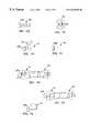
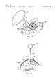
- FIG. 1is an idealized perspective view of a tissue mass and surrounding tissue volume that is bracketed by the markers of the present invention, with two markers being positioned on opposite ends of each of mutually orthogonal X, Y and Z axes intersecting the tissue mass so as to define the boundary of the tissue volume, and with the probe and detector of the present invention being positioned adjacent the tissue volume;
- FIG. 1 ais a perspective view of the tissue mass illustrated in FIG. 1, with two markers being positioned on opposite ends of each of mutually orthogonal X 1 , Y 1 and Z axes and with two markers being positioned on opposite ends of mutually orthogonal X 2 and Y 2 axes which are mutually orthogonal with respect to the Z axis and offset along with Z axis with respect to the X 1 and Y 1 axes;
- FIG. 1 bis a perspective view of the tissue volume illustrated in FIG. 1, with two markers being positioned on opposite ends of each of V, W, X and Y axes, all of which lie in a common plane and are mutually orthogonal with respect to a Z axis, all of these axes intersecting the tissue mass;
- FIGS. 2 a - 2 gare schematic representations of various embodiments of the markers of the present invention and their associated detection characteristics
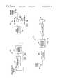
- FIG. 3 ais a block diagram of the elements of one embodiment of the marker illustrated in FIG. 2 c;
- FIG. 3 bis a block diagram of the RF exciter used with the marker illustrated in FIG. 3 a;
- FIG. 4is a block diagram of the elements of one embodiment of the marker illustrated in FIG. 2 e;
- FIG. 5is a block diagram of the RF exciter used with the marker illustrated in FIG. 4;
- FIG. 6is a perspective view of one embodiment of the marker illustrated in FIG. 2 f , with details of internal construction being illustrated in phantom view;
- FIG. 7is a block diagram of the probe and detector used with the marker illustrated in FIG. 2 b;
- FIG. 8is a block diagram of the probe and detector used with the marker illustrated in FIG. 2 c;
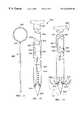
- FIG. 9is an exploded perspective view of the cutter of the present invention, with the two portions of the cutter being shown in disengaged, spaced relation;
- FIG. 10is a perspective view of the cutter illustrated in FIG. 9, with the two portions of the cutter being shown in engaged, cooperative relation;
- FIG. 11is a front elevation view of the tissue anchor of the present invention, with the cannula and rod of the cutter being shown in broken view to facilitate illustration;
- FIG. 12is an enlarged view of the tissue anchor in FIG. 11, with the rod and cannula both being broken at first location and the rod alone being broken at a second location to facilitate illustration, also with the rod being shown in a retracted position relative to the cannula;
- FIG. 13is similar to FIG. 12, except that the rod is shown in the extended position relative to the cannula, with the anchor members attached to the end of the rod being shown in an extended position engaged in a portion of a tissue mass;
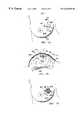
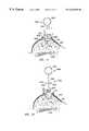
- FIG. 14is a top view of a breast of woman in a supine position, with a tissue mass being surrounded by markers of the present invention so as to define the tissue volume to be removed, and with an incision formed in the skin of the breast above the tissue volume;
- FIG. 15is a cross-sectional view of the breast of FIG. 14 taken along line 15 — 15 in FIG. 14;
- FIG. 16is similar to FIG. 14, except that the skin adjacent the incision has been pulled apart to provide access to underlying breast tissue;
- FIG. 17is an enlarged view of the incision of FIG. 16, with the tissue anchor illustrated in FIGS. 11-13 being positioned in the tissue mass, and the two portions of the cutter illustrated in FIGS. 9 and 10 and probe of the present invention all being positioned adjacent the surgical cavity;
- FIG. 18is similar to FIG. 15, except that an incision has been formed in the skin of the breast and has been retracted to provide access to the underlying tissue mass to be removed and the tissue anchor has been positioned above the breast;
- FIG. 19is an enlarged view of the portion of the breast illustrated in FIG. 18 containing the tissue mass to be removed, with the tissue anchor being positioned in the tissue mass in the extended position so that the anchor members of the tissue anchor engage the tissue mass;
- FIG. 20is similar to FIG. 17, except that the two portions of the cutter are illustrated in engaged, cooperative relationship and are positioned under the skin in contact with the tissue volume to be removed;
- FIG. 21is similar to FIG. 18, except that the tissue cutter is illustrated surrounding the tissue anchor and in cutting engagement with the tissue volume to be removed;
- FIG. 22is similar to FIG. 21, except that the tissue volume has been completely removed from the breast and is illustrated immediately above the surgical opening in engagement with the tissue anchor and cutter.
- the present inventionis a system 20 for defining the boundaries of, i.e., bracketing, a tissue volume 22 in a tissue portion 24 .
- tissue volume 22will include a tissue mass 26 , e.g., a breast lesion, that is targeted for removal and a tissue margin 28 of unaffected tissue surrounding the tissue mass.
- system 20can be used to locate the defined boundaries of the tissue volume, e.g., in connection with the surgical removal of tissue mass 26 .
- the present inventionis also directed to a method of bracketing tissue volume 22 using system 20 , and a method of removing tissue volume 22 using system 20 .
- These methodscan be advantageously, although not necessarily, accomplished with other aspects of the present invention, i.e., cutting tool 200 (FIGS. 9 and 10) and tissue anchor 300 (FIGS. 11 - 13 ), both described below.
- System 20comprises a plurality of markers 30 , a probe 32 and a detector 34 connected to the probe.
- markers 30are implanted in tissue portion 24 under the guidance of a conventional imaging system not forming part of the present invention, so as to bracket tissue volume 22 .
- imaging systemsmay include ultrasound, magnetic resonance imaging (“MRI”), computer-aided tomography (“CAT”) scan, and X-ray systems.
- Markers 30are imagable with the imaging energy generated by the imaging system. For example, if an ultrasound imaging system is used to implant markers 30 , the latter are configured and made from a material that strongly reflects ultrasound energy. Materials that are imagable with the energy generated by such systems are well known to those skilled in the art, and so are not described in detail here.
- probe 32 and detector 34are used to locate the markers, as described in more detail below.
- probe 32and “detector 34 ” are used generically herein to refer to all embodiments of the probe and detector described below. Specific embodiments of the probe 32 and detector 34 are identified using a prime notation described below, i.e., probe 32′ or detector 34′′.
- markers 30are biologically inert and are relatively small so that they interfere as little as possible with the removal or other treatment of tissue volume 22 .
- Markers 30may have different geometric configurations, e.g., spherical, disk-like, cylindrical.
- the greatest dimension of a marker 30is not more than about 5 mm.
- markers 30are even smaller, i.e., the greatest dimension is about 1-2 mm.
- markers 30each have a detection characteristic to enable detection by probe 32 and detector 34 .
- the detection characteristics of the various embodiments of markers 30can be characterized as active or passive.
- the detection characteristic of a first embodiment of marker 30illustrated in FIG. 2 a as marker 30 a , is gamma rays 40 .
- marker 30 amay include materials such as technetium 99 , cobalt isotopes or iodine isotopes. Such materials may be obtained from DuPont of Billerica, Mass.
- each marker 30 agenerates gamma rays 40 having a field strength in the range of 1-100 microCurries.
- the detection characteristicis magnetic field 42 .
- Markers 30 b of the second embodimentthus contain ferromagnetic materials in which a magnetic field can be induced, or alternatively are permanently magnetized and so have an associated permanent magnetic field.
- magnetic field 42represents both the induced and inherent magnetic fields. Strong permanent magnets, such as those made from Samarium-Cobalt, are typically preferred for markers 30 b.
- marker 30 cemits radio frequency (“RF”) signal 44 in response to a triggering signal 46 .
- RFradio frequency
- Various energy sourcesmay be used for triggering signal 46 , including a magnetic field, ultrasound or radio frequency energy.
- marker 30 cis preferably designed to receive triggering signal 46 which has a first RF wavelength, and in response thereto, emit signal 44 of a second RF wavelength.
- no dataother than the specific radio frequency itself, is carried in signal 44 .
- markers 30 cmay all transmit signal 44 at a single frequency, with data uniquely identifying each marker being carried in signal 44 emitted by each marker.
- a suitable marker 30 cis illustrated in FIG. 3 a .
- This marker 30 cincludes a transmit/receive antenna 52 for receiving an RF signal at a first frequency and transmitting an RF signal at a second frequency. Also included is a power detect/regulate circuit 54 connected to antenna 52 that detects the presence of, and regulates, the RF signal received by the antenna. The regulated RF signal is provided from circuit 54 to drive radio frequency generator 56 which generates an RF signal at a second frequency. As discussed in more detail below, when multiple markers 30 c are used together in a given bracketing procedure, preferably each marker transmits RF signals at a second frequency which is unique to the marker.
- the RF signal generated by radio frequency generator 56is then provided to antenna 52 where it is transmitted as an RF signal. While it is preferred the frequency of RF signal 44 transmitted from markers 30 c be unique for each marker 30 c used in a given bracketing procedure, the frequency of the received RF signal 46 is preferably common with respect to all of the markers 30 c used in the bracketing procedure.
- RF exciter 60for generating RF signal 46 is illustrated.
- RF exciter 60includes a radio frequency generator 62 for generating RF signal 46 at a predetermined frequency and an RF amplifier 64 for amplifying the output from the radio frequency generator.
- the sensitivity of amplifier 64may be controlled using gain adjustment 62 coupled to the amplifier.
- the output of RF amplifier 64is provided to transmit antenna 68 which transmits RF signal 46 .
- Transmit antenna 68 of RF exciter 60is preferably placed in relatively close proximity to marker 30 c , with appropriate gain adjustment of RF amplifier 64 being achieved by control gain adjustment 66 until a suitable return signal is absorbed from detector 34 ′′, discussed below and illustrated in FIG. 8 .
- marker 30 dagain in the active category, marker 30 d , illustrated in FIG. 2 d , continuously emits signal 44 at specific frequencies in the radio frequency spectrum.
- the marker 30 c illustrated in FIG. 3 a and described abovecan be satisfactorily employed as marker 30 d by adding a battery (not shown) in place of power detector portion of circuit 54 of marker 30 c .
- RF exciter 60is not required in connection with marker 30 d , insofar as the battery generates the energy used by the marker in producing RF signal 44 .
- marker 30 eis designed to vibrate following implantation.
- This vibrationis a detection characteristic that is chosen to enhance image contrast when marker 30 is intended to be detected using a probe 32 and detector 34 that perform ultrasound imaging. More specifically, incoming ultrasound signal 74 is reflected off marker 30 e as reflected ultrasound signal 76 , with a Doppler shift component being added to the reflected signal due to the vibration of the marker to enhance imagability of the marker.
- the vibration frequency of marker 30 ewill vary depending upon the frequency of ultrasound energy generated by probe 32 , but is preferably lower than the frequency of incoming ultrasound signal 74 which is typically 7.5 MHz, i.e., the vibration frequency is preferably in the 50 Hz to 50 KHz range.
- FIG. 4A suitable marker 30 e that achieves the functionality described above is illustrated in FIG. 4 .
- This marker 30 eincludes an antenna 80 for receiving an RF signal that provides the energy driving the marker.
- a power detection and regulation circuit 82is connected to antenna 80 for detecting when the antenna is receiving an RF signal and for regulating the signal for use by oscillator and waveform generator circuit 84 connected to circuit 82 .
- Circuit 84converts the regulated RF signal received from circuit 82 into an oscillating electrical signal, preferably in the audio frequency range (i.e., 20 Hz-20 kHz), having a waveform that is optimized to drive piezo-electric device 86 connected to circuit 84 .
- Piezo-electric device 86is a conventional piezo-electric device of the type that converts an oscillating electrical input signal into mechanical oscillations. Piezo-electric device 86 is attached via support 88 to outer housing 90 of marker 30 e . Housing 90 is designed to resonate at the mechanical oscillation frequency of piezo-electric device 86 .
- an RF coupled acoustic exciter 92is provided for generating the RF signal received by antenna 80 of marker 30 e .
- Exciter 92includes a radio frequency generator 94 for generating an RF signal.
- RF amp 96with a gain adjustment 98 connected thereto, is provided for receiving and amplifying the output signal from generator 94 .
- a transmit antenna 100is provided for receiving the output of amp 96 and transmitting the RF signal used to drive marker 30 e .
- gain 98 of amp 96is adjusted to amplify the RF signal produced by generator 94 such that marker 30 e is caused to mechanically oscillate so it is most clearly observable by the ultrasound imaging system (not shown) used in conjunction with marker 30 e.
- a frequency divider circuit(not shown) may be used in place of oscillator/waveform generator circuit 84 .
- exciter 92is modified to include a variable frequency oscillator (not shown) in place of radio frequency generator 94 .
- the detection characteristic in a sixth embodiment of marker 30is opacity to incoming ultrasound signal 74 . That is, marker 30 f reflects incoming sound energy sufficiently to create a strong image in reflected signal 76 so as to enhance imagability using a conventional ultrasound imaging system. In many cases, it will be advantageous to incorporate the detection characteristics of marker 30 f in marker 30 e.
- FIG. 6While those skilled in the art are familiar with materials and configurations that can be used for marker 30 f , one suitable marker 30 f is illustrated in FIG. 6 .
- This marker 30 fincludes plate 102 , plate 104 and plate 106 , all of which are preferably arranged in mutually orthogonal relationship. It is preferred that each of the plates 102 - 106 has a square configuration and the length of each edge of the plates, e.g., the length of edge 108 of plate 104 , is preferably about twice the wavelength of incoming ultrasound signal 74 . For example, when incoming ultrasound signal 74 has a wavelength of 7.5 MHz, edge 108 has a length of about 2 mm.
- Plates 102 - 106are made from a material that strongly reflects ultrasound energy, e.g., aluminum, and typically have a thickness in the range of 10-100 ⁇ m. Plates 102 - 106 ideally are enclosed in a biologically non-reactive casing 110 .
- the latteris preferably made from a material that does not have strong ultrasound reflection characteristics, e.g., a soft polymer.
- marker 30 g of the seventh embodimentcomprises a capsule (not shown) filled with a colored dye 78 , e.g., a vital dye.
- a colored dye 78e.g., a vital dye.
- Either or both the capsule and dye 78 of marker 30 gare made from a material that is imagable by the imaging system, e.g., ultrasound, used to implant the markers, as described in more detail below.
- the capsuleis made from gelatin or other suitable material that is selected to be sufficiently tough to withstand insertion into tissue volume 22 , but is relatively easily cut by the cutting tool used to remove the tissue volume, e.g., a conventional surgical scalpel or cutting tool 200 described below.
- Marker 30 gprovides a visual guide as to its location by releasing colored dye 78 when severed by a surgical cutting tool. In this regard, probe 32 and detector 34 are not used in connection with marker 30 g.
- Markers 30 a , 30 b and 30 fmay be made from a solid structure containing material having the desired detection characteristic.
- markers 30 a , 30 b and 30 fmay be made from a capsule filled with a dye, such as is used for marker 30 g , containing material having the desired detection characteristic.
- all embodiments of markers 30may include a dye contained in an outer capsule having the requisite toughness and severability characteristics noted above.
- detector 34is designed to provide humanly recognizable information when probe 32 is positioned within a selected proximity, e.g., 1-5 cm, of a given marker. This information may take one of a variety of forms, including a burst of humanly perceivable sound, constant or intermittent illumination of a light, movement of a needle on a dial, a short burst of air, change of data in a visual display, increased image brightness or contrast (in the case when detector 34 is an ultrasound imaging system, as discussed below) or other humanly perceivable proximity information.
- detector 34may include a dial 112 , light 114 , speaker 116 , or other appropriate devices for generating the selected form of humanly perceivable information.
- detector 34provides humanly recognizable information that indicates changes in proximity of probe 32 to a given marker 30 .
- detector 34preferably provides proximity information having an attribute or characteristic that varies as a function of changes in proximity of the probe relative to the marker. For example, if the proximity information is sound, the pitch is varied with changes in proximity. Or, as another example, if the proximity information is light, the brightness of the light changes with changes in proximity.
- a probe and detector that may be satisfactorily employed as probe 32 and detector 34 , respectively, when the latter is intended to detect maker 30 ais sold by Care Wise Medical Products Corporation of Morgan Hill, Calif. and is identified by the trademark C-TRAK.
- the C-TRAK probewhich is described in U.S. Pat. Nos. 5,170,055 and 5,246,005 to Carroll et al., which are incorporated herein by reference, provides a humanly audible sound, the pitch of which varies with changes in proximity of the probe to tissue labeled with gamma ray producing material.
- probe 32 and detector 34when probe 32 and detector 34 are intended for use in detecting marker 30 b , which generates a magnetic field 42 , probe 32 ′ and detector 34 ′ illustrated in FIG. 7 may be satisfactorily employed.
- Probe 32 ′includes a conventional Hall effect sensor (not shown) that provides an output signal on line 120 , the voltage of which varies as a function of proximity of the probe to the magnetic field generated by a marker 30 b .
- Detector 34 ′is connected to probe 32 ′ via line 120 , and includes an amplifier 122 connected to line 120 for amplifying the signal from the Hall effect sensor in probe 32 ′.
- Amplifier 122includes an offset adjustment 126 and a gain adjustment 128 . Offset adjustment 126 is provided to cancel the effects of any ambient magnetic fields, such as that of the earth.
- Gain adjustment 128is provided to control the overall sensitivity of detector 34 ′.
- the amplified signal from amplifier 122is delivered on line 124 to signal meter 126 , which may comprise a dial with a movable needle, an LED or other device for representing signal strength. Also connected to line 124 is voltage controlled oscillator 128 , the output of which is provided to amplifier 130 . The output of amplifier 130 drives speaker 116 .
- the frequency of the output signal from voltage controlled oscillator 128varies as function of changes in voltage of the signal delivered on line 124 , which in turn causes the pitch of the sound produced by speaker 116 to vary as a function of changes in the voltage of the signal on line 124 .
- other devices for providing humanly recognizable information representing changing proximitye.g., a light may be employed instead of speaker 116 .
- probe 32 ′′ and detector 34 ′′are provided for use in detecting the markers.
- Probe 32 ′′includes a conventional coil antenna 140 for receiving an RF signal.
- Detector 34 ′′includes a selectable notch filter 142 connected to antenna 140 which permits tuning of the detector to the unique RF frequency of signal 44 emitted by markers 30 c or 30 d .
- a tuning knob or other user adjustable mechanismis attached to selectable notch filter 142 to permit a user to perform such tuning.
- the output of selectable notch filter 142is provided to RF amplifier 144 , the overall sensitivity of which may be controlled by gain adjustment 146 attached to the amplifier.
- the output of RF amplifier 144is provided to rectifier/integrator circuit 148 which rectifies and time filters the signal.
- the output of rectifier/integrator circuit 148is provided to analog signal strength display 150 which provides a visual indication of the proximity of probe 32 ′′ to marker 30 c .
- the output of rectifier/integrator circuit 148is provided to voltage oscillator 152 which generates an output signal, the frequency of which varies as a function of the voltage level of the signal provided by rectifier/integrator circuit 148 .
- the output signal of the voltage control oscillator 152is amplified by audio amplifier 154 , which in turn drives speaker 116 . Accordingly, the pitch of the sound generated by speaker 116 varies as a function of the strength of the RF signal received by probe 32 ′′, and hence as a function of the proximity of probe 32 ′′ to markers 30 c or 30 d.
- a suitable probe 32 and detector 34 for use with the markers 30 e and 30 fis the ultrasound imaging system available from Dornier Surgical Products, Inc., Phoenix, Ariz., is identified by the name Performa, and generates ultrasound energy having a frequency of 7.5 MHZ.
- tissue volume 22 that is bracketed with markers 30may be surgically removed using one of a variety of tools. Referring to FIGS. 9 and 10, one of these tools is cutter 200 .
- Cutter 200includes portions 202 and 204 .
- Portion 202has a curved plate 206 that preferably traverses an arc of 180°, as measured between ends 208 and 210 .
- Plate 206includes a bottom edge 212 that is preferably sharpened.
- Plate 206also includes a top edge 214 that is typically blunt.
- Portion 202also includes a handle 220 having an elongate central section 222 and a transverse section 224 attached to an upper end of the central section.
- transverse section 224extends normally to the long axis of central section 222 , although other non-orthogonal relationships are encompassed by the present invention.
- Handle 220is attached to curved plate 206 by several, e.g., three, spokes 226 that are attached to the plate at spaced locations and extend radially inwardly from the plate toward the bottom end of central section 222 where they are also attached.
- Handle 220also includes apertures 228 and 230 . As illustrated in FIGS. 9 and 10, apertures 228 and 230 are positioned at the upper end of handle 220 .
- Handle central section 222also includes an elongate groove 232 extending the length of the central section.
- Portion 204is nearly identical to portion 202 .
- portion 204includes a curved plate 236 that traverses an arc of 180° between ends 238 and 240 , has a bottom edge 242 that is preferably sharpened, and has a top edge 244 .
- Portion 204also includes a handle 250 having a central section 252 and a transverse section 254 , with central section 252 and curved plate 236 being connected by spokes 256 .
- Handle central section 252includes an elongate groove 255 extending the length of the central section. The placement of groove 255 on central section 252 is selected so that when portion 202 and 204 are positioned in operative engagement, as illustrated in FIG.
- groove 255confronts groove 232 in central section 222 , and together the grooves form a central bore extending the length of central sections 222 and 252 .
- the thickness of plate 236is preferably the same as the thickness of plate 236 , as measured between edges 212 and 214 . This thickness is typically in the range of 2 mm-25 mm.
- Portion 204differs from portion 202 in that it includes projections 258 and 260 in place of apertures 228 and 230 .
- Projections 258 and 260are sized and positioned to be snugly received in apertures 228 and 230 , respectively, when portions 202 and 204 are positioned in operative engagement, as illustrated in FIG. 10 .
- Transverse section 252is preferably positioned relative to central section 250 so that when portions 202 and 204 are positioned in operative engagement, transverse section 252 extends in an opposite direction relative to transverse section 224 .
- portions 202 and 204When portions 202 and 204 are assembled to perform a cutting operation, they confront and engage one another, as illustrated in FIG. 10 .
- the radii of curvature of curved plates 206 and 236are preferably substantially identical so that when end 210 contacts end 238 and end 208 contacts end 240 , as illustrated in FIG. 10, plates 206 and 236 form a circular structure.
- central sections 222 and 250contact one another, with a central rotational axis 262 extending between the sections along their longitudinal axes.
- apertures 228 and 230receive projections 258 and 260 , respectively, which ensures a rotational force applied about axis 262 to one of transverse sections 224 and 252 is transmitted from one of portions 202 and 204 to the other.
- connectors or other engagement mechanismsbe provided for releasably securing portion 202 in operative engagement with portion 204 , as illustrated in FIG. 10, so that both portions rotate together when a rotational force is applied to one of the portions, as described in more detail below in connection with the discussion of the operation of cutter 200 .
- Such connectors or other engagement mechanismsmay be provided at ends 208 , 210 , 240 and 242 , where spokes 226 join and spokes 256 join, or at other appropriate locations.
- Cutter 200is preferably made from stainless steel. However, other materials including aluminum and certain plastics may be used in the construction of cutter 200 .
- tissue anchor 300is designed to stabilize tissue mass 26 during surgical removal of the mass using system 20 , as described in more detail below.
- Tissue anchor 300includes a ring 302 sized to receive the thumb or finger of a user, and a rod 304 .
- the latterincludes a proximal end 305 , which is attached to ring 302 , and a distal end 306 .
- Rod 304includes an outwardly projecting pin 308 that serves as a stop, as described below.
- Tissue anchor 300also includes a plurality of, e.g., four, anchor members 310 that are attached to rod 304 at or adjacent its distal end 306 .
- anchor members 310are attached to rod 304 so as to extend away from its distal end 306 , as illustrated in FIGS. 12 and 13 .
- anchor member 310may be attached to rod 304 so as to extend away from distal end 306 toward proximal end 305 (not shown). Each anchor member 310 may terminate with a barb 312 (FIG. 13 ), if desired.
- Anchor members 310preferably have a curved configuration when in an unbiased state, as illustrated in FIGS. 11 and 13. Anchor members 310 are preferably made from spring steel, although other “memory” metal alloys made also be satisfactorily used. In certain applications it may be unnecessary to provide a curve in anchor member 310 , i.e., the anchor member may be substantially straight.
- Rod 304preferably, although not necessarily, has a circular cross section.
- the outside diameter of rod 304depends upon its intended application, but is typically in the range of 0.3-10 mm, preferably about 1-2 mm.
- the length of rod 304as measured between proximal end 305 and distal end 306 , also depends upon its desired application, but typically ranges from 5-20 cm.
- Tissue anchor 300also includes a cannula 320 having a central bore 322 , a proximal end 324 and a pointed distal end 326 .
- Central bore 322has an inside diameter that is sized to receive rod 304 with a close sliding fit.
- Cannula 320has an outside diameter that is selected based on the intended application but is typically in the range 0.5 mm-12 mm, preferably about 1-3 mm.
- Cannula 320also includes an elongate slot 328 that runs parallel to the long axis of the cannula and is sized to receive pin 308 with a close sliding fit. The length of slot 328 is substantially the same as the length of anchor members 310 .
- Slot 328includes a pocket 329 at its end closest to distal end 326 of cannula 320 that extends orthogonally to the long axis of the slot and is sized to receive pin 308 .
- Cannula 320also includes a plurality of apertures 330 extending through the wall of the cannula. Apertures 330 are positioned adjacent distal end 326 of cannula 320 when anchor members 310 are attached to rod 304 to extend away from distal end 306 as illustrated in FIGS. 12 and 13. If anchor members 310 extend from distal end 306 toward proximal end 305 (not shown), then apertures 330 are moved toward the proximal end so that they are spaced from the proximal at least about the length of the anchor members. One aperture 330 is typically provided for each anchor member 310 .
- anchor members 310 , cannula 320 , and slot 328are together selected so that a small portion, e.g., about 1 mm, of each anchor member 310 projects from its respective aperture 330 when tissue anchor 300 is in the retracted position illustrated in FIG. 12 .
- pin 308engages the end of slot 328 closest to proximal end 324 .
- Anchor members 310are sized in this manner to ensure the anchor members remain positioned in their respective apertures 330 when tissue anchor 300 is in the retracted position illustrated in FIG. 12 .
- the lengths of anchor members 310 , cannula 320 , and slot 328are also together selected so that most, if not substantially the entire, length of the anchor members 310 projects from their respective apertures 330 when tissue anchor is in the extended position illustrated in FIGS. 11 and 13. In this position, pin 308 engages the end of slot 328 closest to distal end 326 .
- tissue anchor 300is preferably made from stainless steel, a plastic such as polystyrene or polyurethane, or other materials suitable for the intended application of the tissue anchor (as described in more detail below) known to those skilled in the art. As noted above, in many cases it is desirable to make anchor members 310 from spring steel or a “memory” metal alloy.
- markers 30may be used to bracket (i.e., define the boundaries of) tissue volume 22 in a tissue portion 24 in accordance with the following method.
- tissue volume 22may be present in other organs and structures, e.g., a liver, or may constitute an entire organ or structure.
- tissue mass 26 of interestis identified through conventional imaging methods, e.g., ultrasound, MRI, X-ray or CAT scan.
- markers 30are implanted in tissue portion 24 surrounding tissue mass 26 and defining outer boundaries of tissue volume 22 .
- the number of markers 30 used, and the placement of the markers relative to tissue mass 26will vary depending upon the location of the tissue mass relative to other types of tissue, e.g., bone or muscle, surgeon preference, size and configuration of the tissue mass and the desired amount of tissue margin 28 (FIG. 1) beyond the edge of tissue mass 26 .
- At least six markers 30to bracket tissue volume 22 , preferably two on each of axes X, Y and Z (see FIGS. 1, 14 and 15 ).
- the two markers 30are positioned on each of axes X, Y and Z so as to lie on opposite boundaries of tissue volume 22 .
- marker 30lies on the Z axis at the upper surface of tissue volume 22
- marker 30 2lies on the Z axis at the lower surface of the tissue volume
- marker 30 3lies on the X axis at a first location on the outer surface of the tissue volume
- marker 30 4lies on the X axis at a second location on the outer surface of the tissue volume diametrically opposite marker 3 3
- marker 30 5lies on the Y axis at a third location on the outer surface of the tissue volume
- marker 30 6lies on the Y axis at a fourth location on the outer surface of the tissue volume diametrically opposite marker 30 5 .
- tissue volume 22be completely surrounded by markers 30 , i.e., that the tissue volume be defined in three dimensions by the markers.
- the marker 30such as marker 30 2 shown in FIGS. 1 and 15, positioned at the base of, i.e., underneath, tissue volume 22 is not typically required when a different type of tissue, such as pectoral muscle 400 (FIG. 15) is located at or near where the marker would be positioned.
- FIG. 15The illustration of marker 30 2 in FIG.
- tissue volume 22is not inconsistent with this recommended placement regime for markers 30 because of the relatively great spacing between the marker 30 2 and pectoral muscle 400 .
- the marker 30such as marker 30 1 shown in FIG. 1
- to be positioned on top of tissue volume 22is near the skin overlying the tissue volume, such marker is not typically required.
- the X, Y and Z axesare illustrated in FIG. 1 as intersecting at a common point centrally located within tissue mass 26 , this is not required. For example, it may be desirable to offset the X and Y axes somewhat, as measured along the Z axis.
- markers 30are used, two on the Z axis, two on an axis X 1 , two on an axis X 2 that is offset along the Z axis with respect to axis X 1 , two on an axis Y 1 , and two on an axis Y 2 that is offset along the Z axis with respect to axis Y 1 .
- ten markers 30are used, two on the Z axis, two on an axis X 1 , two on an axis X 2 that is offset along the Z axis with respect to axis X 1 , two on an axis Y 1 , and two on an axis Y 2 that is offset along the Z axis with respect to axis Y 1 .
- markers 30are used, two on the X axis, two on the Y axis, two on the Z axis, two on the V axis which bisects the X and Y axes and two on the W axis which also bisects the X and Y axes, but at a different location.
- Other numbers and relative placements of markersare also encompassed by the present invention.
- Markers 30are preferably spaced from tissue mass 26 so as to define tissue volume 22 such that tissue margin 28 is large enough to ensure none of the tissue mass lies outside the tissue volume. This precise spacing will vary with the nature of the tissue mass 26 , the size of the tissue mass, surgeon preference and other factors. However, tissue margin 28 , as measured outwardly along an axis extending perpendicular to a surface location on tissue mass 26 , is generally about 0.5 cm to 3 cm, and is preferably about 1 cm to 2 cm.
- Markers 30may be implanted in tissue portion 24 in a variety of different ways using a variety of different tools.
- markers 30are implanted using a conventional imaging system (not shown) that simultaneously generates an image of tissue mass 26 and the markers. By frequently comparing the location of markers 30 to tissue mass 26 during implantation of the markers into tissue portion 24 , based on image information received from the imaging system, the markers may be positioned so as to define tissue volume 22 in the manner described above.
- markers 30are made from a material that provides good image contrast with respect to the imaging energy used.
- tissue portion 24it is preferable to at least partially immobilize tissue portion 24 during implantation of markers 30 .
- thisis less critical than might be expected because by comparing the relative location of a marker 30 to tissue mass 26 , the desired relative placement can typically be achieved, even if tissue portion 24 is moving during marker implantation.
- markers 30 in tissue portion 24may be implanted in various techniques.
- one approachis to insert markers 30 percutaneously through skin 402 overlying tissue portion 24 using known needle pushers or implanters (neither shown) of the type used to implant “seeds” of radioactive material for various cancer treatments.
- needle pushersof the type sold by Best Industries of Springfield, Virginia, may be satisfactorily employed.
- These needle pushersinclude a central needle surrounded by an outer tube having an end plate or cup for supporting the radioactive “seed.” Following insertion of the needle pusher into the selected tissue mass, the radioactive “seed” is released by pressing the central needle downwardly relative to the surrounding outer tube, with the point of the needle ejecting the “seed” from the end plate or cup of the outer tube.
- the markeris positioned on the end of the needle pusher (in place of the radioactive “seed”), is forced through skin 402 and, using feedback from the imaging system, is guided to the region where it is desired to implant the marker. Then the marker 30 is ejected from the needle pusher by urging the central needle forwardly into the inner tube.
- a second approach for implanting markers 30involves creating a small, e.g., 5-10 mm, incision (not shown) in the skin 402 (see FIGS. 1 and 14) overlying tissue portion 24 .
- a scalpelis inserted through the incision so as to form a slit in the underlying tissue portion extending to the position where it is desired to implant a maker 30 .
- a marker 30is inserted through the slit to such position using a tweezers, needle pusher, trocar or other suitable tool.
- Other markers 30are implanted through separate incisions in skin 402 in similar manner so as to bracket tissue volume 22 .
- a third approach for implanting markers 30is to form a relative large, e.g., 1-3 cm, incision 404 (see FIG. 14) in skin 402 overlying tissue mass 26 .
- incision 404is pulled open as illustrated in FIG. 16 using retractors or other conventional devices so as to form a relatively large open region 406 above tissue mass 26 .
- Markers 30are then implanted into tissue portion 24 using either the first or second approaches described above.
- markers 30are also encompassed by the present invention.
- the speed and accuracy with which markers 30 may be implanted, and minimizing trauma associated with implantation,are important objectives to consider in selecting other approaches for implanting markers 30 .
- tissue volume 22can be removed using either of two procedures encompassed by the present invention.
- the first procedureinvolves identifying the boundaries of tissue volume 22 using an embodiment of probe 32 and detector 34 that is appropriate for the type of marker 30 used, as discussed above. Using information from detector 34 regarding such boundaries, tissue volume 22 is then removed using a scalpel, cutter 200 or other tool, with tissue anchor 300 preferably, but not necessarily, being used to stabilize the tissue volume during removal.
- the second procedureis similar to the first, except that tissue anchor 300 is not used.
- the surgeontypically identifies the boundaries of the tissue volume using system 20 . This step is generally needed because in practice markers 30 will often be implanted by another doctor, e.g., a radiologist, as a separate procedure.
- the boundaries of tissue volume 22are identified by moving probe 32 in the general region of the tissue volume and then monitoring the detection information (e.g., sound, light, dial movement, image clarity and the like) provided by detector 34 .
- detector 34may provide this information when probe 32 is moved within a predetermined proximity of a given marker 30 , or may provide this information in a form that changes with changes in proximity of the probe to the marker (e.g., a light gets brighter as the probe is moved toward a marker and dimmer as it is moved away).
- the interaction between marker 30 and probe 32 and detector 34depends upon the detection characteristic of the marker.
- a probe and detector of the type described in U.S. Pat. Nos. 5,170,055 and 5,246,005 to Carroll et al.may be satisfactorily used to detect the markers.
- the C-TRAK probeincludes a radiation detector, e.g., a scintillation crystal, which provides an output signal that is believed to vary as a function of the flux density of the gamma rays 40 emitted by marker 30 a .
- Changes in this output signalare then converted into humanly recognizable detection information, e.g., sound, having a characteristic, i.e., pitch or tempo in the case of sound, that varies with changes in gamma ray flux density.
- detection informatione.g., sound
- a characteristici.e., pitch or tempo in the case of sound
- the surgeoncan mentally note where the marker is located. Repetition of this process will result in identification of the location of all markers 30 a.
- probe 32 ′ and detector 34 ′are used to detect the marker.
- the surgeonmoves probe 32 ′ in the general region of tissue volume 22 , with the result that as the probe approaches a given marker 30 b its Hall effect sensor (not shown) generates an output signal having a voltage that increases as the probe is moved toward the marker. Similarly the voltage of the output signal decreases as probe 32 ′ is moved away from the marker 30 b .
- the output signal of probe 32 ′is-provide via line 120 to amplifier 122 , which amplifies the output signal from the probe.
- the amplified-voltage signal from probe 32 ′is displayed on signal meter 126 and is also delivered to voltage controlled oscillator 128 .
- the lattergenerates an oscillating signal, the frequency of which varies as a function of the voltage of the amplified signal provided to voltage controlled oscillator 128 .
- This signalis then amplified by amplifier 130 , and the amplified signal then drives speaker 116 such that the pitch of the sound provided by the speaker 116 varies as a function of proximity of probe 32 ′ to marker 30 b .
- the surgeoncan assess when the probe 32 ′ is positioned closest to a selected marker 30 b . Repetition of this process will result in identification of the location of all of markers 30 b.
- marker 30 cwhich generates an RF signal 44 , is identified using probe 32 ′′ and detector 34 ′′ in the following manner.
- RF exciter 60is operated so as to produce an RF exciter signal 46 .
- radio frequency generator 62(FIG. 3 b ) generates a radio frequency signal which is amplified by RF amplifier 64 , following sensitivity adjustment using gain adjustment 66 , with the amplified signal being provided to antenna 68 for transmission to markers 30 c .
- RF exciter 60is positioned sufficiently close to markers 30 c that RF exciter signal 46 is received by antenna 52 of the markers and is of sufficient strength to drive radio frequency generator 56 of the markers.
- radio frequency generator 56Following detection and regulation by circuit 54 (FIG. 3 a ) of the signal 46 received by antenna 52 , radio frequency generator 56 generates an RF signal which is transmitted by antenna 52 as RF signal 44 .
- each marker 30 ctransmits RF signal 44 at a frequency that is unique to the marker, while an RF exciter signal 46 having a single frequency is preferably used for all of the markers 30 c , with the frequency of signal 46 being different than the frequency of signal 44 .
- a given marker 30 ce.g., marker 30 c 1
- a corresponding representation on the adjustment knobthat controls selectable notch filter 142 , e.g., the reference number “ 1 ”
- the surgeoncan identify the location of the given marker.
- the knob for adjusting selectable notch filter 142is then moved to a different position when detecting a second marker 30 c , e.g., marker 30 c 2 .
- Signals from receive antenna 140 that are passed through selectable notch filter 142are then amplified by RF amplifier 144 with the adjustment of the amplifier gain being provided as needed using gain adjustment 146 .
- the amplified signalis then provided to rectifier/integrator 148 where the signal is rectified and time filtered.
- the strength of signal 144 detected by detector 34 ′′is then displayed via analog signal strength display 150 and is provided to voltage controlled oscillator 152 .
- the lattercreates an oscillating signal, the frequency of which varies as a function of the voltage of the signal provided by rectifier/integrator 148 .
- the output signal from voltage controlled oscillator 152is then amplified by audio amplifier 154 and delivered to drive speaker 116 .
- the pitch of the sound provided by speaker 116will vary as a function of the frequency of the signal provided by voltage controlled oscillator 152 , and as an ultimate function of the proximity of probe 32 ′′ to a given marker 30 c .
- the surgeoncan mentally note where the marker is located.
- all of the markers 30 cmay be located.
- marker 30 dmay also be detected using detector 34 ′′ in substantially the same manner discussed above with respect to marker 30 c .
- probe 32includes a conventional ultrasound transducer (not shown) that generates ultrasound in a conventional frequency range, e.g., 7.5 MHz, and receives back reflection of the ultrasound signal.
- Detector 34is the image processor and display (neither shown) of a conventional ultrasound apparatus which is connected to the ultrasound transducer. Markers 30 e or 30 f are identified by scanning the general region of tissue volume 22 with probe 32 , and monitoring the ultrasound image of the markers provided by detector 34 . This ultrasound image permits the surgeon to identify the placement of all of the markers, and hence the boundaries of tissue volume 22 .
- marker 30 eIn the case of marker 30 e , the latter is caused to vibrate at a frequency that is generally significantly less than that of the ultrasound generated by the ultrasound transducer in probe 32 . This creates, through what is believed to be a Doppler shift phenomenon, enhanced image contrast in the ultrasound signal reflected off markers 30 e .
- Vibration of a marker 30 eis effected by operating RF exciter 92 so that radio frequency generator 94 generates a radio frequency signal which is amplified by amp 96 and then transmitted by antenna 100 .
- Antenna 80 of marker 30 ereceives this RF signal, which is detected and regulated by circuit 84 so as to generate an oscillating electrical signal that is provided to piezo-electric device 86 .
- This signalcauses the piezo-electric device 86 to mechanically oscillate, which oscillations are transferred via support 88 to outer housing 90 of marker 30 e , thereby causing the housing (and hence the marker) to vibrate.
- tissue volume 22Following identification of tissue volume 22 using the procedures outlined above, surgical removal of the tissue volume commences.
- the first of the two procedures for removing tissue volume 22 referenced abovecommences with the formation of an incision 404 (FIG. 14) in skin 402 above tissue volume 22 .
- the length of incision 404is typically about equal to, or slightly greater than, the distance between two markers 30 lying on a given axis, e.g., the Y axis as illustrated in FIG. 14 .
- portions of skin 402 adjacent incision 404are pulled apart by retractors or other known devices, so as to form open region 406 (FIG. 16) and expose tissue portion 24 beneath.
- tissue anchor 300is inserted in tissue mass 26 so as to assume the extended position illustrated in FIG. 13 .
- Thisis achieved by inserting a finger into ring 302 , then pulling rod 30 4 upwardly (as illustrated in FIG. 12) with respect to cannula 320 so that pin 308 moves in slot 328 toward the end thereof closest to proximal end 324 of the cannula.
- cannula 320is grasped and is inserted through open region 406 into tissue volume 22 so that its distal end 326 is positioned substantially in the center of tissue mass 26 .
- This placementmay be achieved under the guidance of an imaging system (not shown) that is capable of imaging tissue anchor 300 , e.g., ultrasound or X-ray imaging systems.
- an imaging system(not shown) that is capable of imaging tissue anchor 300 , e.g., ultrasound or X-ray imaging systems.
- the location a marker 30 2 lying beneath tissue volume 22is identified using the procedure described above to identify the tissue volume.
- distal end 326may be positioned centrally within tissue mass 26 .
- ring 302and hence rod 304 attached thereto, is forced downwardly (as viewed in FIG. 17) relative to cannula 320 until pin 308 contacts the end of slot 328 closest to distal end 326 .
- anchor members 310are forced out through apertures 330 and into tissue mass 26 (see FIG. 19 ).
- ring 302 , and hence rod 304is rotated slightly so as to cause pin 308 to move into pocket 329 .
- cutter portions 202 and 204are positioned adjacent open region 406 , as illustrated in FIG. 17 .
- cutter portion 202is positioned in open region 406 , with its curved plate 206 being inserted under portions of skin 402 adjacent the open region, as illustrated in FIG. 20 .
- cutter portion 204is similarly positioned in open region 406 .
- portions 202 and 204are moved toward one another so that cannula 320 of tissue anchor 300 is received in elongate groove 232 in central handle section 222 and in elongate groove 255 in central handle section 252 .
- Portions 202 and 204are moved even closer to one another so that central handle sections 222 and 252 engage one another and so that projections 258 and 260 are received, respectively, in apertures 228 and 230 .
- ends 208 and 210 of curved portion 206 of cutter portion 202engage, respectively, ends 240 and 238 of curved portion 236 of cutter portion 204 , so as to form a substantially continuous curved cutting edge consisting of cutting edges 212 and 242 .
- longitudinal axis 262 of cutter 200extends substantially parallel to the elongate axis of cannula 320 , both of which are substantially co-axial with the Z axis extending through tissue volume 22 . (See FIGS. 18 and 21 ).
- the position of cutter 200 relative to markers 30is determined by comparing the location of markers, which is typically determined by using probe 32 and detector 34 in the manner described above, to the position of the cutter. Then, the location of cutter 200 is adjusted so that axis 262 of cutter 200 is substantially co-axial with Z axis tissue volume 22 , as illustrated in FIG. 21 . In some cases the surgeon will recall the location of markers 30 from the prior marker identification step, and so it will be unnecessary to again locate the markers. However, when tissue portion 24 is amorphous and pliable, as is the case when breast tissue is involved, it is recommended that this alignment of cutter 200 with tissue portions 30 using probe 32 and detector 34 be performed before any cutting of tissue volume 22 commences.
- an appropriately sized cutter 200is selected such that the radius of curved plates 206 and 236 , as measured radially outwardly from axis 262 , is substantially the same as the radius of tissue volume 22 as measured radially outward from the Z axis. While this relationship between the radii of curved plates 206 and 236 of cutter 200 and the radius of tissue volume 22 as measured with respect to Z axis, is preferred, in some cases it may be satisfactory to use a cutter having a radius that is greater than or less than the radius of the tissue volume 22 . Also, the height of curved portions 206 and 236 is another factor considered in selecting an appropriate cutter 200 .
- ring 302 of tissue anchor 300is typically pulled upwardly in the direction of arrow F (see FIGS. 19 and 21) sufficiently to tension tissue volume 22 and adjacent portions of tissue portion 24 .
- this tensioning of tissue volume 22 and tissue portion 24the tendency of the tissue portion to compress under the force of a cutting device is reduced. Also, this tensioning of tissue volume 22 serves to stabilize the tissue volume during the surgical removal process.
- tissue stabilizationcan be achieved merely by holding tissue anchor 300 in a substantially fixed position relative to tissue volume 22 . In other words, no force in the direction of arrow F is applied to tissue anchor 300 except as may be necessary to hold the tissue anchor in a stable position.
- handles 220 and 250 of cutter 200are rotated about cutter axis 262 in either or both a clockwise and counterclockwise direction, i.e., in the direction indicated by curved arrow R (see FIG. 21 ).
- Elongate grooves 232 and 255are sized to permit cutter 200 to rotate relatively freely about cannula 320 positioned therein.
- Pins 258 and 260 and associated apertures 228 and 230are provided to ensure portions 202 and 204 remain operatively engaged with one another as illustrated in FIG. 10, and so that the portions rotate together when a rotational force is applied to one of the portions.
- bottom edges 212 and 242begin cutting tissue volume 22 along its outer boundary.
- Progress in removing tissue volume 22is generally periodically determined by comparing the position of curve plates 206 and 236 of cutter 200 relative to markers 30 using probe 32 and detector 34 to identify the locations of markers 30 and then comparing such locations with the location of the cutter.
- a determinationcan be made as to when tissue volume 22 has been severed from tissue portion 24 to a depth defined by marker 30 2 (FIG. 21) defining the bottom or innermost portion of the tissue volume.
- cutter 200can be removed from tissue portion 24 , as indicated in FIG. 22 .
- markers 30may remain in place in tissue portion 24 following removal of tissue volume 22 , as indicated in FIG. 22 . If such as the case, markers 30 are then subsequently removed by first locating the markers using probe 32 and detector 34 and then removing the markers with a suitable instrument, e.g., tweezers. In other cases, the markers will be included in the tissue volume 22 .
- a suitable instrumente.g., tweezers
- tissue anchor 300 and cutter 200may be used to perform this final severing of the tissue volume.
- the precise location where this final incision is mademay be determined by again locating the position of marker 30 2 using probe 32 and detector 34 .
- a surgeoncan typically follow the incision created by cutter 200 with a scalpel or other tool down to the region where marker 30 2 is located and tissue volume 22 remains attached to tissue portion 24 .
- a marker 30 2is not required when the bottom or innermost portion of tissue volume 22 is positioned immediately above a different type of tissue, e.g., a pectoral muscle 400 .
- the surgeoncan assess when cutter 200 has been inserted sufficiently deep into tissue portion 24 by merely observing when bottom cutting edges 212 and 242 are about to engage the different type of tissue.
- the relative depth of cutter 200 in tissue portion 24can be determined by locating specific markers using probe 32 and detector 34 . The location of such markers 30 is then compared with the location of cutter 200 to determine the depth of the cut. For example, if markers 30 c are installed at positions X 1 and X 2 in FIG. 1 a , and each marker has a unique frequency, these markers can be uniquely identified by detector 34 ′′ (FIG. 8) in the manner described above.
- the boundaries of tissue volume 22can often be more readily defined during the removal of the tissue volume. This is so because increasing the number of markers 30 used increases the quantity of information received from detector 34 regarding the boundaries of tissue volume 22 .
- cutter 200in connection with the removal tissue volume 22 often expedites removal of the tissue volume
- use of the cutteris not a mandatory aspect of the present method of bracketing and removing the tissue volume.
- a conventional scalpelmay often be satisfactorily employed in place of cutter 200 .
- the process of removing tissue volume 22 using a scalpelalso preferably commences by inserting tissue anchor 300 in tissue volume 22 in the manner described above.
- the location of markers 30are also determined prior to and during the removal of tissue volume 22 by scalpel in the manner described above.
- the boundaries thereofmay be repeatedly identified by locating markers 30 using probe 32 and detector 34 .
- tissue anchor 300it is generally advantageous to use tissue anchor 300 when removing tissue volume 22 with a scalpel because by stabilizing the tissue volume and surrounding regions of tissue portion 24 , it is easier to maintain alignment of the scalpel with the boundaries of the tissue volume.
- tissue anchor 300is a preferred, but not essential, aspect of the present method of bracketing and removing tissue volume 22 .
- markers 30 gare not used in connection with marker 30 g .
- the detection characteristic of markers 30 gis the release of a colored dye 78 in surgical cavity adjacent the markers. Removal of a tissue volume 22 bracketed by markers 30 g differs from the removal of tissue volume when bracketed by the other embodiments of marker 30 in that the location of marker 30 g is not determined by the surgeon prior to initiation of the removal of tissue volume 22 . Practically speaking, this is more a difference in the process for removing tissue volume 22 than a difference in the composition and construction of marker 30 g .
- marker 30 gmust necessarily be imagable by some form of imaging system, which imaging system could, in most cases, also be used by the surgeon to identify the location of marker 30 g prior to and in connection with the removal of tissue volume 22 .
- imaging systemcould, in most cases, also be used by the surgeon to identify the location of marker 30 g prior to and in connection with the removal of tissue volume 22 .
- marker 30 gis initially implanted by imaging the marker using an ultrasound system, then marker 30 g is actually a marker 30 f .
- the markersare not located by the surgeon prior to, or in connection with, the removal of tissue volume other than by visual observation, as discussed below.
- Removal of tissue volume 22 bracketed by markers 30 galso preferably commences by installing tissue anchor 300 as described above. Again, the use of tissue anchor 300 is preferred, but not mandatory.
- the surgeoncommences cutting the general region of tissue volume 22 , which can be defined by colored marks, Kopanz needles or other known techniques.
- the removal of tissue volume 22proceeds using either cutter 200 , or a scalpel or other cutting device, as described above.
- tissue anchor 300if used, is manipulated to stabilize tissue volume 22 in the manner described above.
- cutter 200the scalpel or other cutting device encounters a marker 30 g , the capsule of the marker is severed releasing the colored dye 78 .
- markers 30 g defining one side of the boundary of tissue volume 22may be advantageous to use a given color of dye in markers 30 g defining one side of the boundary of tissue volume 22 , while the markers 30 g defining an opposite side include a different color of dye.
- the boundary of tissue volume 22can typically be identified by iteratively cutting and observing whether dye appears in the surgical cavity.
- marker embodiments 30 a - 30 fmay all include colored dye 78 within an outer capsule that is sufficiently tough to withstand insertion and yet is relatively easily cut by cutter 200 , a scalpel or other cutting device. Such use of dye in markers 30 provides another source of information for the surgeon regarding the boundary of tissue volume 22 .
- tissue bracketing system 20is that is permits the relatively precise identification of the boundaries of tissue volume 22 without the need for needles, wires or other cumbersome apparatus projecting from tissue portion 24 . As such, bracketing system permits a surgeon to relatively quickly and easily identify the tissue boundary of tissue volume 22 and remove the tissue volume. In addition, system 20 is ideally adopted for bracketing a tissue volume 22 in amorphous, pliable tissue, such as breast tissue.
- cutter 200permits a tissue volume 22 of relatively large diameter to be removed through a relatively small incision 404 . This advantage is important in this era when tissue-conserving therapies are being emphasized.
- tissue anchor 300By stabilizing tissue volume 22 using tissue anchor 300 , the accuracy with which a surgeon can remove tissue volume 22 is enhanced.
- This advantage of the present inventionarises because tensioning of the tissue volume 22 by pulling upwardly on tissue anchor 300 serves to retain the tissue portion in a relatively stable position. Indeed, even holding tissue anchor 300 in a substantially fixed position relative to the tissue volume 22 with which it is engaged typically provides beneficial stabilization of the tissue volume.
- cutter 200 and tissue anchor 300may be advantageously employed in connection with the present method of bracketing and removing tissue volume 22 , it is to be appreciated that the cutter and tissue anchor have application in many other contexts. More specifically, in any application in which it is desired to remove a volume of tissue through as small an incision as possible, cutter 200 has important utility. Similarly, when it is desired to stabilize a piece of tissue in connection with surgical removal or other treatment of the piece of tissue, whether or not within the bracketing context of the present invention, tissue anchor 300 also has important application.
Landscapes
- Health & Medical Sciences (AREA)
- Surgery (AREA)
- Life Sciences & Earth Sciences (AREA)
- Engineering & Computer Science (AREA)
- Molecular Biology (AREA)
- Public Health (AREA)
- Veterinary Medicine (AREA)
- Biomedical Technology (AREA)
- Heart & Thoracic Surgery (AREA)
- Medical Informatics (AREA)
- Nuclear Medicine, Radiotherapy & Molecular Imaging (AREA)
- Animal Behavior & Ethology (AREA)
- General Health & Medical Sciences (AREA)
- Pathology (AREA)
- Oral & Maxillofacial Surgery (AREA)
- Robotics (AREA)
- Ultra Sonic Daignosis Equipment (AREA)
- Surgical Instruments (AREA)
- Treatment Of Liquids With Adsorbents In General (AREA)
- Enzymes And Modification Thereof (AREA)
- Apparatus For Radiation Diagnosis (AREA)
- Gripping Jigs, Holding Jigs, And Positioning Jigs (AREA)
- Investigating Or Analysing Biological Materials (AREA)
Abstract
Description
Claims (26)
Priority Applications (28)
| Application Number | Priority Date | Filing Date | Title |
|---|---|---|---|
| US09/078,982US6363940B1 (en) | 1998-05-14 | 1998-05-14 | System and method for bracketing and removing tissue |
| KR1020007012734AKR20010043593A (en) | 1998-05-14 | 1999-05-14 | System And Method For Bracketing And Removing Tissue |
| AT99923067TATE488183T1 (en) | 1998-05-14 | 1999-05-14 | TISSUE STAPLES SYSTEM |
| PCT/US1999/010683WO1999058065A1 (en) | 1998-05-14 | 1999-05-14 | System and method for bracketing and removing tissue |
| EP99923067AEP1094752B8 (en) | 1998-05-14 | 1999-05-14 | System for bracketing tissue |
| DE69942946TDE69942946D1 (en) | 1998-05-14 | 1999-05-14 | SYSTEM FOR CLAMPS OF TISSUE |
| IL13962999AIL139629A0 (en) | 1998-05-14 | 1999-05-14 | System and method for bracketing and removing tissue |
| JP2000547919AJP4294220B2 (en) | 1998-05-14 | 1999-05-14 | System and method for batch removal of tissue |
| AU39921/99AAU3992199A (en) | 1998-05-14 | 1999-05-14 | System and method for bracketing and removing tissue |
| EP10184572AEP2289423A1 (en) | 1998-05-14 | 1999-05-14 | System for bracketing tissue |
| AU2001217752AAU2001217752A1 (en) | 1998-05-14 | 2000-11-17 | Systems and methods for stabilizing a targert location within a human body |
| PCT/US2000/031673WO2002039918A1 (en) | 1998-05-14 | 2000-11-17 | Systems and methods for stabilizing a targert location within a human body |
| PCT/US2000/031667WO2002039917A1 (en) | 1998-05-14 | 2000-11-17 | Systems and methods for locating and defining a target location within a human body |
| DE60043022TDE60043022D1 (en) | 1998-05-14 | 2000-11-17 | SYSTEMS FOR STABILIZING A TARGET POSITION IN A HUMAN BODY |
| AU2001217746AAU2001217746A1 (en) | 1998-05-14 | 2000-11-17 | Systems and methods for locating and defining a target location within a human body |
| EP00980498AEP1341466B1 (en) | 1998-05-14 | 2000-11-17 | Systems for stabilizing a target location within a human body |
| AT00980498TATE443486T1 (en) | 1998-05-14 | 2000-11-17 | SYSTEMS FOR STABILIZING A TARGET POSITION IN A HUMAN BODY |
| EP00980492AEP1341465B1 (en) | 1998-05-14 | 2000-11-17 | System for locating and defining a target location within a human body |
| EP09156994AEP2119412A1 (en) | 1998-05-14 | 2000-11-17 | Wireless marker for use in localizing a target of a patient |
| US09/815,393US6918919B2 (en) | 1998-05-14 | 2001-03-22 | System and method for bracketing and removing tissue |
| US09/954,588US6675810B2 (en) | 1998-05-14 | 2001-09-14 | System and method for bracketing and removing tissue |
| US10/047,735US6698433B2 (en) | 1998-05-14 | 2002-01-14 | System and method for bracketing and removing tissue |
| US10/438,550US20030192557A1 (en) | 1998-05-14 | 2003-05-14 | Systems and methods for locating and defining a target location within a human body |
| US10/745,104US8452375B2 (en) | 1998-05-14 | 2003-12-23 | Systems and methods for locating and defining a target location within a human body |
| US10/791,662US20050059884A1 (en) | 1998-05-14 | 2004-03-02 | System and method for bracketing and removing tissue |
| US11/635,441US20070265491A1 (en) | 1998-05-14 | 2006-12-06 | Systems and methods for stabilizing a target location within a human body |
| US12/697,139US20100137712A1 (en) | 1998-05-14 | 2010-01-29 | Systems and methods for stabilizing a target location within a human body |
| US12/697,160US20100137713A1 (en) | 1998-05-14 | 2010-01-29 | Systems and methods for stabilizing a target location within a human body |
Applications Claiming Priority (2)
| Application Number | Priority Date | Filing Date | Title |
|---|---|---|---|
| US09/078,982US6363940B1 (en) | 1998-05-14 | 1998-05-14 | System and method for bracketing and removing tissue |
| PCT/US1999/010683WO1999058065A1 (en) | 1998-05-14 | 1999-05-14 | System and method for bracketing and removing tissue |
Related Child Applications (6)
| Application Number | Title | Priority Date | Filing Date |
|---|---|---|---|
| PCT/US2000/031667Continuation-In-PartWO2002039917A1 (en) | 1998-05-14 | 2000-11-17 | Systems and methods for locating and defining a target location within a human body |
| PCT/US2000/031673Continuation-In-PartWO2002039918A1 (en) | 1998-05-14 | 2000-11-17 | Systems and methods for stabilizing a targert location within a human body |
| US09/815,393DivisionUS6918919B2 (en) | 1998-05-14 | 2001-03-22 | System and method for bracketing and removing tissue |
| US09/954,588ContinuationUS6675810B2 (en) | 1998-05-14 | 2001-09-14 | System and method for bracketing and removing tissue |
| US10/047,735ContinuationUS6698433B2 (en) | 1998-05-14 | 2002-01-14 | System and method for bracketing and removing tissue |
| US41682703AContinuation-In-Part | 1998-05-14 | 2003-05-14 |
Publications (1)
| Publication Number | Publication Date |
|---|---|
| US6363940B1true US6363940B1 (en) | 2002-04-02 |
Family
ID=38814541
Family Applications (5)
| Application Number | Title | Priority Date | Filing Date |
|---|---|---|---|
| US09/078,982Expired - LifetimeUS6363940B1 (en) | 1998-05-14 | 1998-05-14 | System and method for bracketing and removing tissue |
| US09/815,393Expired - LifetimeUS6918919B2 (en) | 1998-05-14 | 2001-03-22 | System and method for bracketing and removing tissue |
| US09/954,588Expired - LifetimeUS6675810B2 (en) | 1998-05-14 | 2001-09-14 | System and method for bracketing and removing tissue |
| US10/047,735Expired - LifetimeUS6698433B2 (en) | 1998-05-14 | 2002-01-14 | System and method for bracketing and removing tissue |
| US10/791,662AbandonedUS20050059884A1 (en) | 1998-05-14 | 2004-03-02 | System and method for bracketing and removing tissue |
Family Applications After (4)
| Application Number | Title | Priority Date | Filing Date |
|---|---|---|---|
| US09/815,393Expired - LifetimeUS6918919B2 (en) | 1998-05-14 | 2001-03-22 | System and method for bracketing and removing tissue |
| US09/954,588Expired - LifetimeUS6675810B2 (en) | 1998-05-14 | 2001-09-14 | System and method for bracketing and removing tissue |
| US10/047,735Expired - LifetimeUS6698433B2 (en) | 1998-05-14 | 2002-01-14 | System and method for bracketing and removing tissue |
| US10/791,662AbandonedUS20050059884A1 (en) | 1998-05-14 | 2004-03-02 | System and method for bracketing and removing tissue |
Country Status (9)
| Country | Link |
|---|---|
| US (5) | US6363940B1 (en) |
| EP (1) | EP1094752B8 (en) |
| JP (1) | JP4294220B2 (en) |
| KR (1) | KR20010043593A (en) |
| AT (1) | ATE488183T1 (en) |
| AU (1) | AU3992199A (en) |
| DE (1) | DE69942946D1 (en) |
| IL (1) | IL139629A0 (en) |
| WO (1) | WO1999058065A1 (en) |
Cited By (137)
| Publication number | Priority date | Publication date | Assignee | Title |
|---|---|---|---|---|
| US20010018594A1 (en)* | 1998-05-14 | 2001-08-30 | Calypso Medical, Inc. | System and Method for Bracketing and Removing Tissue |
| US20020087095A1 (en)* | 1998-03-03 | 2002-07-04 | Senorx, Inc. | Methods and apparatus for securing medical instruments to desired locations in a patient's body |
| US20020102212A1 (en)* | 2000-11-09 | 2002-08-01 | Black Robert D. | Methods, circuits and compositions of matter for in vivo detection of biomolecule concentrations using fluorescent tags |
| US20030012731A1 (en)* | 2001-04-23 | 2003-01-16 | Steven Suddarth | Systems, methods and devices for in vivo monitoring of a localized response via a radiolabeled analyte in a subject |
| US20030018358A1 (en)* | 1999-06-25 | 2003-01-23 | Vahid Saadat | Apparatus and methods for treating tissue |
| US20030026758A1 (en)* | 2001-07-27 | 2003-02-06 | Baker Gregg S. | Method and device for monitoring real-time position of an area targeted by a radiosurgery system |
| US20030052785A1 (en)* | 2001-09-14 | 2003-03-20 | Margo Gisselberg | Miniature resonating marker assembly |
| US20030092985A1 (en)* | 1998-10-06 | 2003-05-15 | Cox Charles E. | Radio guided seed localization of imaged lesions |
| US20030125616A1 (en)* | 2001-11-30 | 2003-07-03 | Black Robert D. | Disposable single-use external dosimeters for use in radiation therapies |
| US20030158498A1 (en)* | 2002-02-19 | 2003-08-21 | Mohamed Bakry | Pleural biopsy and brushing needle |
| US20030181794A1 (en)* | 2002-01-29 | 2003-09-25 | Rini Christopher J. | Implantable sensor housing, sensor unit and methods for forming and using the same |
| US20030195523A1 (en)* | 2002-04-16 | 2003-10-16 | Futsz Richard C. | Skin marking for indicating subdermal chip |
| US20030192557A1 (en)* | 1998-05-14 | 2003-10-16 | David Krag | Systems and methods for locating and defining a target location within a human body |
| US6716179B2 (en)* | 1998-03-03 | 2004-04-06 | Senorx, Inc. | Sentinel node location and biopsy |
| US20040101479A1 (en)* | 1999-02-02 | 2004-05-27 | Senorx, Inc. | Biopsy site marker and process and apparatus for applying it |
| US20040125916A1 (en)* | 2002-12-30 | 2004-07-01 | Herron Matthew A. | Panel-type sensor/source array assembly |
| US20040124105A1 (en)* | 2002-12-30 | 2004-07-01 | Keith Seiler | Packaged systems for implanting markers in a patient and methods for manufacturing and using such systems |
| US20040127787A1 (en)* | 2002-12-30 | 2004-07-01 | Dimmer Steven C. | Implantable marker with a leadless signal transmitter compatible for use in magnetic resonance devices |
| US20040133101A1 (en)* | 2001-06-08 | 2004-07-08 | Mate Timothy P. | Guided radiation therapy system |
| US6782289B1 (en)* | 1999-10-08 | 2004-08-24 | The Board Of Trustees Of The Leland Stanford Junior University | Methods and apparatus for characterizing lesions in blood vessels and other body lumens |
| US20040197267A1 (en)* | 2003-02-19 | 2004-10-07 | Black Robert D. | In vivo fluorescence sensors, systems, and related methods operating in conjunction with fluorescent analytes |
| US6812842B2 (en) | 2001-12-20 | 2004-11-02 | Calypso Medical Technologies, Inc. | System for excitation of a leadless miniature marker |
| US6822570B2 (en) | 2001-12-20 | 2004-11-23 | Calypso Medical Technologies, Inc. | System for spatially adjustable excitation of leadless miniature marker |
| US6838990B2 (en) | 2001-12-20 | 2005-01-04 | Calypso Medical Technologies, Inc. | System for excitation leadless miniature marker |
| US20050080337A1 (en)* | 1998-12-24 | 2005-04-14 | Vivant Medical, Inc. | Biopsy site marker |
| US20050154293A1 (en)* | 2003-12-24 | 2005-07-14 | Margo Gisselberg | Implantable marker with wireless signal transmitter |
| US20050154283A1 (en)* | 2003-12-31 | 2005-07-14 | Wright J. N. | Marker localization sensing system synchronized with radiation source |
| US20050151649A1 (en)* | 2002-12-30 | 2005-07-14 | Wright J. N. | Receiver used in marker localization sensing system and tunable to marker frequency |
| US20050154284A1 (en)* | 2003-12-31 | 2005-07-14 | Wright J. N. | Method and system for calibration of a marker localization sensing array |
| US20050154280A1 (en)* | 2003-12-31 | 2005-07-14 | Wright J. N. | Receiver used in marker localization sensing system |
| US20050234336A1 (en)* | 2004-03-26 | 2005-10-20 | Beckman Andrew T | Apparatus and method for marking tissue |
| US6991643B2 (en) | 2000-12-20 | 2006-01-31 | Usgi Medical Inc. | Multi-barbed device for retaining tissue in apposition and methods of use |
| US20060036164A1 (en)* | 2001-06-19 | 2006-02-16 | The Trustees Of The University Of Pennsylvania | Optically guided system for precise placement of a medical catheter in a patient |
| US20060047317A1 (en)* | 2004-08-31 | 2006-03-02 | Patrick Murphy | Multi-frequency electrical field generator and use thereof |
| US20060052694A1 (en)* | 2004-07-23 | 2006-03-09 | Phillips Stephen C | Modular software system for guided radiation therapy |
| US20060058648A1 (en)* | 2004-07-23 | 2006-03-16 | Eric Meier | Integrated radiation therapy systems and methods for treating a target in a patient |
| US20060063999A1 (en)* | 2004-07-23 | 2006-03-23 | Calypso Medical Technologies, Inc. | User interface for guided radiation therapy |
| US20060078086A1 (en)* | 2004-07-23 | 2006-04-13 | Riley James K | Dynamic/adaptive treatment planning for radiation therapy |
| US20060100509A1 (en)* | 2004-07-23 | 2006-05-11 | Wright J N | Data processing for real-time tracking of a target in radiation therapy |
| US20060276680A1 (en)* | 2002-12-30 | 2006-12-07 | Calypso Medical Technologies, Inc. | Apparatuses and methods for percutaneously implanting objects in patients |
| US20070055090A1 (en)* | 2004-08-12 | 2007-03-08 | Navotek Medical Ltd. | Medical Treatment System and Method |
| US20070118213A1 (en)* | 2005-11-23 | 2007-05-24 | Didier Loulmet | Methods, devices, and kits for treating mitral valve prolapse |
| US20070161884A1 (en)* | 2003-04-02 | 2007-07-12 | Sicel Technologies, Inc. | Methods, systems, and computer program products for providing dynamic data of positional localization of target implants |
| US20070225596A1 (en)* | 2004-05-03 | 2007-09-27 | Micropos Medical Ab | Implant, Apparatus and Method for Tracking a Target Area |
| US20070265491A1 (en)* | 1998-05-14 | 2007-11-15 | Calypso Medical Technologies, Inc. | Systems and methods for stabilizing a target location within a human body |
| US20080132800A1 (en)* | 2006-11-30 | 2008-06-05 | Hettrick Douglas A | Novel medical methods and systems incorporating wireless monitoring |
| US20080140180A1 (en)* | 2006-12-07 | 2008-06-12 | Medtronic Vascular, Inc. | Vascular Position Locating Apparatus and Method |
| US20080139915A1 (en)* | 2006-12-07 | 2008-06-12 | Medtronic Vascular, Inc. | Vascular Position Locating and/or Mapping Apparatus and Methods |
| US20080147173A1 (en)* | 2006-12-18 | 2008-06-19 | Medtronic Vascular, Inc. | Prosthesis Deployment Apparatus and Methods |
| EP1943974A1 (en) | 2007-01-12 | 2008-07-16 | Medtronic Vascular, Inc. | Vessel position and configuration imaging apparatus and methods |
| EP1943988A1 (en) | 2007-01-12 | 2008-07-16 | Medtronic Vascular, Inc. | Prosthesis deployment apparatus and methods |
| US20080188921A1 (en)* | 2007-02-02 | 2008-08-07 | Medtronic Vascular, Inc. | Prosthesis Deployment Apparatus and Methods |
| US20080238046A1 (en)* | 2007-03-29 | 2008-10-02 | Giddings Joshua J | Air bag bracket/fastener |
| US20080262473A1 (en)* | 2004-10-19 | 2008-10-23 | Navotek Medical Ltd. | Locating a Catheter Tip Using a Tracked Guide |
| US20080281323A1 (en)* | 1999-01-27 | 2008-11-13 | Burbank Fred H | Tissue specimen isolating and damaging device and method |
| US20080294039A1 (en)* | 2006-08-04 | 2008-11-27 | Senorx, Inc. | Assembly with hemostatic and radiographically detectable pellets |
| WO2007137124A3 (en)* | 2006-05-17 | 2008-12-11 | Univ Utah Res Found | Devices and methods for fluorescent inspection and/or removal of material in a sample |
| US20090127459A1 (en)* | 2004-08-12 | 2009-05-21 | Navotek Medical Ltd. | Localization of a Radioactive Source |
| US20090131734A1 (en)* | 2006-02-16 | 2009-05-21 | Navotek Medical Ltd. | Implantable medical marker and methods of preparation thereof |
| US7561051B1 (en)* | 2005-04-20 | 2009-07-14 | Creare Inc. | Magnet locating apparatus and method of locating a magnet using such apparatus |
| US20090209804A1 (en)* | 2004-07-23 | 2009-08-20 | Calypso Medical Technologies, Inc. | Apparatuses and methods for percutaneously implanting objects in patients |
| US20090259284A1 (en)* | 2008-04-10 | 2009-10-15 | Medtronic Vascular, Inc. | Resonating Stent or Stent Element |
| US20090259296A1 (en)* | 2008-04-10 | 2009-10-15 | Medtronic Vascular, Inc. | Gate Cannulation Apparatus and Methods |
| US20090299174A1 (en)* | 2004-01-12 | 2009-12-03 | Calypso Medical Technologies, Inc. | Instruments with location markers and methods for tracking instruments through anatomical passageways |
| US20100042041A1 (en)* | 2008-08-18 | 2010-02-18 | Navotek Medical Ltd. | Implantation device for soft tissue markers and other implants |
| US20100207765A1 (en)* | 2009-02-13 | 2010-08-19 | Christopher Brander | Method and apparatus for locating passive integrated transponder tags |
| US20100234726A1 (en)* | 1998-12-24 | 2010-09-16 | Sirimanne D Laksen | Device and method for safe location and marking of a biopsy cavity |
| US20100317968A1 (en)* | 2004-07-23 | 2010-12-16 | Wright J Nelson | Systems and methods for real-time tracking of targets in radiation therapy and other medical applications |
| WO2010151843A2 (en) | 2009-06-26 | 2010-12-29 | Cianna Medical, Inc. | Apparatus, systems, and methods for localizing markers or tissue structures within a body |
| US20110011917A1 (en)* | 2008-12-31 | 2011-01-20 | Hansen Medical, Inc. | Methods, devices, and kits for treating valve prolapse |
| US7926491B2 (en) | 2002-12-31 | 2011-04-19 | Calypso Medical Technologies, Inc. | Method and apparatus for sensing field strength signals to estimate location of a wireless implantable marker |
| US7976539B2 (en) | 2004-03-05 | 2011-07-12 | Hansen Medical, Inc. | System and method for denaturing and fixing collagenous tissue |
| US20110237943A1 (en)* | 2003-05-23 | 2011-09-29 | Senorx, Inc. | Fibrous marker and intracorporeal delivery thereof |
| US20110288623A1 (en)* | 2010-05-18 | 2011-11-24 | Rbkpark Llc | Medical device |
| US20110301456A1 (en)* | 2010-06-07 | 2011-12-08 | Malignext Targeting Technologies, Inc. | Tissue Marking for Lesion Removal |
| US8157862B2 (en) | 1997-10-10 | 2012-04-17 | Senorx, Inc. | Tissue marking implant |
| US8164064B2 (en) | 2004-08-12 | 2012-04-24 | Navotek Medical Ltd. | Localization of a radioactive source within a body of a subject |
| US8177792B2 (en) | 2002-06-17 | 2012-05-15 | Senorx, Inc. | Plugged tip delivery tube for marker placement |
| US8219182B2 (en) | 1999-02-02 | 2012-07-10 | Senorx, Inc. | Cavity-filling biopsy site markers |
| US8224424B2 (en) | 1999-02-02 | 2012-07-17 | Senorx, Inc. | Tissue site markers for in vivo imaging |
| US8311610B2 (en) | 2008-01-31 | 2012-11-13 | C. R. Bard, Inc. | Biopsy tissue marker |
| US8361082B2 (en) | 1999-02-02 | 2013-01-29 | Senorx, Inc. | Marker delivery device with releasable plug |
| US8401622B2 (en) | 2006-12-18 | 2013-03-19 | C. R. Bard, Inc. | Biopsy marker with in situ-generated imaging properties |
| US8437834B2 (en) | 2006-10-23 | 2013-05-07 | C. R. Bard, Inc. | Breast marker |
| US8447386B2 (en) | 2003-05-23 | 2013-05-21 | Senorx, Inc. | Marker or filler forming fluid |
| US8486028B2 (en) | 2005-10-07 | 2013-07-16 | Bard Peripheral Vascular, Inc. | Tissue marking apparatus having drug-eluting tissue marker |
| US8498693B2 (en) | 1999-02-02 | 2013-07-30 | Senorx, Inc. | Intracorporeal marker and marker delivery device |
| US8579931B2 (en) | 1999-06-17 | 2013-11-12 | Bard Peripheral Vascular, Inc. | Apparatus for the percutaneous marking of a lesion |
| US8634899B2 (en) | 2003-11-17 | 2014-01-21 | Bard Peripheral Vascular, Inc. | Multi mode imaging marker |
| US8670818B2 (en) | 2008-12-30 | 2014-03-11 | C. R. Bard, Inc. | Marker delivery device for tissue marker placement |
| US8668737B2 (en) | 1997-10-10 | 2014-03-11 | Senorx, Inc. | Tissue marking implant |
| US8718745B2 (en) | 2000-11-20 | 2014-05-06 | Senorx, Inc. | Tissue site markers for in vivo imaging |
| WO2014149183A2 (en) | 2013-03-15 | 2014-09-25 | Cianna Medical, Inc. | Microwave antenna apparatus, systems and methods for localizing markers or tissue structures within a body |
| USD715442S1 (en) | 2013-09-24 | 2014-10-14 | C. R. Bard, Inc. | Tissue marker for intracorporeal site identification |
| USD715942S1 (en) | 2013-09-24 | 2014-10-21 | C. R. Bard, Inc. | Tissue marker for intracorporeal site identification |
| USD716450S1 (en) | 2013-09-24 | 2014-10-28 | C. R. Bard, Inc. | Tissue marker for intracorporeal site identification |
| USD716451S1 (en) | 2013-09-24 | 2014-10-28 | C. R. Bard, Inc. | Tissue marker for intracorporeal site identification |
| US8939153B1 (en) | 2013-03-15 | 2015-01-27 | Health Beacons, Inc. | Transponder strings |
| US9149341B2 (en) | 1999-02-02 | 2015-10-06 | Senorx, Inc | Deployment of polysaccharide markers for treating a site within a patient |
| US9237860B2 (en) | 2008-06-05 | 2016-01-19 | Varian Medical Systems, Inc. | Motion compensation for medical imaging and associated systems and methods |
| US9327061B2 (en) | 2008-09-23 | 2016-05-03 | Senorx, Inc. | Porous bioabsorbable implant |
| US9386942B2 (en) | 2009-06-26 | 2016-07-12 | Cianna Medical, Inc. | Apparatus, systems, and methods for localizing markers or tissue structures within a body |
| US9579077B2 (en) | 2006-12-12 | 2017-02-28 | C.R. Bard, Inc. | Multiple imaging mode tissue marker |
| US9615915B2 (en) | 2014-07-25 | 2017-04-11 | Focal Therapeutics, Inc. | Implantable devices and techniques for oncoplastic surgery |
| US9669113B1 (en) | 1998-12-24 | 2017-06-06 | Devicor Medical Products, Inc. | Device and method for safe location and marking of a biopsy cavity |
| US9713437B2 (en) | 2013-01-26 | 2017-07-25 | Cianna Medical, Inc. | Microwave antenna apparatus, systems, and methods for localizing markers or tissue structures within a body |
| US9730764B2 (en) | 2015-10-02 | 2017-08-15 | Elucent Medical, Inc. | Signal tag detection components, devices, and systems |
| US9750595B2 (en) | 2012-09-28 | 2017-09-05 | Covidien Lp | Implantable medical devices which include grip-members and methods of use thereof |
| US9820824B2 (en) | 1999-02-02 | 2017-11-21 | Senorx, Inc. | Deployment of polysaccharide markers for treating a site within a patent |
| US9848956B2 (en) | 2002-11-18 | 2017-12-26 | Bard Peripheral Vascular, Inc. | Self-contained, self-piercing, side-expelling marking apparatus |
| US9919165B2 (en) | 2014-05-07 | 2018-03-20 | Varian Medical Systems, Inc. | Systems and methods for fiducial to plan association |
| US9943704B1 (en) | 2009-01-21 | 2018-04-17 | Varian Medical Systems, Inc. | Method and system for fiducials contained in removable device for radiation therapy |
| US10043284B2 (en) | 2014-05-07 | 2018-08-07 | Varian Medical Systems, Inc. | Systems and methods for real-time tumor tracking |
| US10143531B2 (en) | 2012-09-28 | 2018-12-04 | Beekley Corporation | Skin marking porous grid and related method of use |
| US10154799B2 (en) | 2016-08-12 | 2018-12-18 | Elucent Medical, Inc. | Surgical device guidance and monitoring devices, systems, and methods |
| US10182868B2 (en) | 2005-11-17 | 2019-01-22 | Varian Medical Systems, Inc. | Apparatus and methods for using an electromagnetic transponder in orthopedic procedures |
| US10188310B2 (en) | 2014-08-24 | 2019-01-29 | Health Beacons, Inc. | Probe for determining magnetic marker locations |
| US10195464B2 (en) | 2004-06-24 | 2019-02-05 | Varian Medical Systems, Inc. | Systems and methods for treating a lung of a patient using guided radiation therapy or surgery |
| US10245119B2 (en) | 2015-10-02 | 2019-04-02 | Elucent Medical, Inc. | Signal tag detection components, devices, and systems |
| US10278779B1 (en) | 2018-06-05 | 2019-05-07 | Elucent Medical, Inc. | Exciter assemblies |
| US10293135B2 (en) | 2010-10-01 | 2019-05-21 | Varian Medical Systems, Inc. | Delivery catheter for and method of delivering implant, for example, bronchoscopically implanting a marker in a lung |
| US10342635B2 (en) | 2005-04-20 | 2019-07-09 | Bard Peripheral Vascular, Inc. | Marking device with retractable cannula |
| US10413381B2 (en) | 2012-04-26 | 2019-09-17 | Focal Therapeutics, Inc. | Surgical implant for marking soft tissue |
| US10610326B2 (en) | 2015-06-05 | 2020-04-07 | Cianna Medical, Inc. | Passive tags, and systems and methods for using them |
| US10653496B2 (en) | 2005-09-19 | 2020-05-19 | Varian Medical Systems, Inc. | Apparatus and methods for implanting objects, such as a bronchoscopically implanting markers in the lung of patients |
| US10660542B2 (en) | 2013-01-26 | 2020-05-26 | Cianna Medical, Inc. | RFID markers and systems and methods for identifying and locating them |
| US10827949B2 (en) | 2016-04-06 | 2020-11-10 | Cianna Medical, Inc. | Reflector markers and systems and methods for identifying and locating them |
| US11179053B2 (en)* | 2004-03-23 | 2021-11-23 | Dilon Medical Technologies Ltd. | Graphical user interfaces (GUI), methods and apparatus for data presentation |
| US11191445B2 (en) | 2015-06-05 | 2021-12-07 | Cianna Medical, Inc. | Reflector markers and systems and methods for identifying and locating them |
| US11259913B2 (en) | 2019-02-06 | 2022-03-01 | Susan Scott | Breast implant with position marker |
| US11344382B2 (en) | 2014-01-24 | 2022-05-31 | Elucent Medical, Inc. | Systems and methods comprising localization agents |
| US11426256B2 (en) | 2016-03-03 | 2022-08-30 | Cianna Medical, Inc. | Implantable markers, and systems and methods for using them |
| US11752361B2 (en) | 2009-06-01 | 2023-09-12 | Hologic, Inc. | Diagnostic or therapeutic procedure using implantable targets |
| US11883150B2 (en) | 2018-09-06 | 2024-01-30 | Cianna Medical, Inc. | Systems for identifying and locating reflectors using orthogonal sequences of reflector switching |
| US12161458B2 (en) | 2019-11-05 | 2024-12-10 | Cianna Medical, Inc. | Systems and methods for imaging a body region using implanted markers |
| US12329510B2 (en) | 2016-06-06 | 2025-06-17 | Temple University—Of the Commonwealth System of Higher Education | Magnetometer surgical device |
| US12383349B2 (en) | 2022-07-26 | 2025-08-12 | Elucent Medical, Inc. | Systems and methods for wireless localization |
Families Citing this family (84)
| Publication number | Priority date | Publication date | Assignee | Title |
|---|---|---|---|---|
| US6402689B1 (en) | 1998-09-30 | 2002-06-11 | Sicel Technologies, Inc. | Methods, systems, and associated implantable devices for dynamic monitoring of physiological and biological properties of tumors |
| US7590441B2 (en)* | 1999-03-11 | 2009-09-15 | Biosense, Inc. | Invasive medical device with position sensing and display |
| US7575550B1 (en) | 1999-03-11 | 2009-08-18 | Biosense, Inc. | Position sensing based on ultrasound emission |
| US7558616B2 (en)* | 1999-03-11 | 2009-07-07 | Biosense, Inc. | Guidance of invasive medical procedures using implantable tags |
| US7549960B2 (en) | 1999-03-11 | 2009-06-23 | Biosense, Inc. | Implantable and insertable passive tags |
| US7174201B2 (en) | 1999-03-11 | 2007-02-06 | Biosense, Inc. | Position sensing system with integral location pad and position display |
| US6306132B1 (en) | 1999-06-17 | 2001-10-23 | Vivant Medical | Modular biopsy and microwave ablation needle delivery apparatus adapted to in situ assembly and method of use |
| DE19956814B4 (en) | 1999-11-25 | 2004-07-15 | Brainlab Ag | Shape detection of treatment devices |
| US6564806B1 (en) | 2000-02-18 | 2003-05-20 | Thomas J. Fogarty | Device for accurately marking tissue |
| WO2001060235A2 (en) | 2000-02-18 | 2001-08-23 | Fogarty Thomas J M D | Improved device for accurately marking tissue |
| US6722371B1 (en) | 2000-02-18 | 2004-04-20 | Thomas J. Fogarty | Device for accurately marking tissue |
| US6878147B2 (en) | 2001-11-02 | 2005-04-12 | Vivant Medical, Inc. | High-strength microwave antenna assemblies |
| US20030130621A1 (en)* | 2002-01-04 | 2003-07-10 | Bryan Vincent E. | Spinal needle system |
| US6752767B2 (en) | 2002-04-16 | 2004-06-22 | Vivant Medical, Inc. | Localization element with energized tip |
| US7197363B2 (en) | 2002-04-16 | 2007-03-27 | Vivant Medical, Inc. | Microwave antenna having a curved configuration |
| US8123698B2 (en)* | 2002-10-07 | 2012-02-28 | Suros Surgical Systems, Inc. | System and method for minimally invasive disease therapy |
| US7311703B2 (en) | 2003-07-18 | 2007-12-25 | Vivant Medical, Inc. | Devices and methods for cooling microwave antennas |
| US20050033157A1 (en)* | 2003-07-25 | 2005-02-10 | Klein Dean A. | Multi-modality marking material and method |
| US8055323B2 (en)* | 2003-08-05 | 2011-11-08 | Imquant, Inc. | Stereotactic system and method for defining a tumor treatment region |
| US7343030B2 (en)* | 2003-08-05 | 2008-03-11 | Imquant, Inc. | Dynamic tumor treatment system |
| US7001341B2 (en) | 2003-08-13 | 2006-02-21 | Scimed Life Systems, Inc. | Marking biopsy sites |
| US8172770B2 (en)* | 2005-09-28 | 2012-05-08 | Suros Surgical Systems, Inc. | System and method for minimally invasive disease therapy |
| US20120289859A9 (en)* | 2003-08-27 | 2012-11-15 | Nicoson Zachary R | System and method for minimally invasive disease therapy |
| JP4578817B2 (en)* | 2004-02-06 | 2010-11-10 | オリンパス株式会社 | Surgical lesion identification system |
| ITTO20040292A1 (en)* | 2004-05-06 | 2004-08-06 | Ezio Visentin | CONNECTION BODY INTENDED TO BE INTRODUCED WITHIN A BONE STRUCTURE OF A HUMAN OR ANIMAL BODY AND SYSTEM FOR THE DETECTION OF AT LEAST A REFERENCE POINT PROVIDED IN THE CONNECTION BODY ITSELF. |
| US8257394B2 (en) | 2004-05-07 | 2012-09-04 | Usgi Medical, Inc. | Apparatus and methods for positioning and securing anchors |
| AU2005270037B2 (en) | 2004-07-02 | 2012-02-09 | The General Hospital Corporation | Endoscopic imaging probe comprising dual clad fibre |
| US8025668B2 (en)* | 2005-04-28 | 2011-09-27 | C. R. Bard, Inc. | Medical device removal system |
| US20080200834A1 (en)* | 2005-09-28 | 2008-08-21 | Mark Joseph L | Introducer device for improved imaging |
| SE529191C8 (en)* | 2005-10-14 | 2007-06-19 | Micropos Medical Ab | A position fastener and a system for detecting the position of such a device |
| US7702378B2 (en) | 2005-11-17 | 2010-04-20 | Breast-Med, Inc. | Tissue marker for multimodality radiographic imaging |
| US11241296B2 (en) | 2005-11-17 | 2022-02-08 | Breast-Med, Inc. | Imaging fiducial markers and methods |
| US7740593B2 (en)* | 2005-12-09 | 2010-06-22 | Senorx, Inc | Guide block for biopsy or surgical devices |
| US8219178B2 (en)* | 2007-02-16 | 2012-07-10 | Catholic Healthcare West | Method and system for performing invasive medical procedures using a surgical robot |
| US8219177B2 (en)* | 2006-02-16 | 2012-07-10 | Catholic Healthcare West | Method and system for performing invasive medical procedures using a surgical robot |
| EP1991121B1 (en)* | 2006-02-16 | 2014-08-06 | Globus Medical, Inc. | System utilizing radio frequency signals for tracking and improving navigation of slender instruments during insertion into the body |
| US20080009895A1 (en)* | 2006-07-05 | 2008-01-10 | Pokomey James L | Vessel cutting tool |
| US8870916B2 (en) | 2006-07-07 | 2014-10-28 | USGI Medical, Inc | Low profile tissue anchors, tissue anchor systems, and methods for their delivery and use |
| US8565853B2 (en)* | 2006-08-11 | 2013-10-22 | DePuy Synthes Products, LLC | Simulated bone or tissue manipulation |
| US20080058673A1 (en)* | 2006-08-29 | 2008-03-06 | Lex Jansen | Tissue extraction device and method of using the same |
| US20080058674A1 (en)* | 2006-08-29 | 2008-03-06 | Lex Jansen | Tissue extraction device and method of using the same |
| US8068921B2 (en) | 2006-09-29 | 2011-11-29 | Vivant Medical, Inc. | Microwave antenna assembly and method of using the same |
| US8113210B2 (en)* | 2006-10-06 | 2012-02-14 | Health Beacons, Inc. | Medical tube and system for locating the same in a body using passive integrated transponders |
| US20080114334A1 (en)* | 2006-11-10 | 2008-05-15 | Voegele James W | Adhesive Marker |
| WO2008097407A2 (en)* | 2006-12-18 | 2008-08-14 | Trillium Precision Surgical, Inc. | Intraoperative tissue mapping and dissection systems, devices, methods, and kits |
| FR2920084B1 (en)* | 2007-08-24 | 2010-08-20 | Endocontrol | IMAGING SYSTEM FOR MONITORING A SURGICAL TOOL IN AN OPERATIVE FIELD |
| US8292880B2 (en) | 2007-11-27 | 2012-10-23 | Vivant Medical, Inc. | Targeted cooling of deployable microwave antenna |
| WO2009087628A2 (en)* | 2008-01-08 | 2009-07-16 | Topshooter Medical Imri Ltd. | Magnetic method and system for locating a target |
| US8177836B2 (en)* | 2008-03-10 | 2012-05-15 | Medtronic, Inc. | Apparatus and methods for minimally invasive valve repair |
| EP2161597B1 (en)* | 2008-09-03 | 2014-06-04 | Brainlab AG | Image-assisted operation system |
| US20100081928A1 (en)* | 2008-09-29 | 2010-04-01 | Searete Llc, A Limited Liability Corporation Of The State Of Delaware | Histological Facilitation systems and methods |
| US8029476B2 (en) | 2008-11-19 | 2011-10-04 | Interrad Medical, Inc. | Anchoring a medical instrument |
| KR101231742B1 (en)* | 2008-12-08 | 2013-02-08 | 한국전자통신연구원 | Minimally invasive particle beam cancer therapy apparatus |
| US8334812B2 (en) | 2009-06-19 | 2012-12-18 | Vivant Medical, Inc. | Microwave ablation antenna radiation detector |
| JP5751642B2 (en) | 2009-09-04 | 2015-07-22 | エリプス テクノロジーズ, インク.Ellipse Technologies, Inc. | Bone growth apparatus and method |
| EP2329786A2 (en) | 2009-10-01 | 2011-06-08 | Navotek Medical Ltd. | Guided surgery |
| JP2013531999A (en) | 2010-05-05 | 2013-08-15 | シー・アール・バード・インコーポレーテッド | System and method for identifying and locating an implanted device |
| US9119655B2 (en) | 2012-08-03 | 2015-09-01 | Stryker Corporation | Surgical manipulator capable of controlling a surgical instrument in multiple modes |
| US9240630B2 (en) | 2011-04-29 | 2016-01-19 | Cyberonics, Inc. | Antenna shield for an implantable medical device |
| US9265958B2 (en) | 2011-04-29 | 2016-02-23 | Cyberonics, Inc. | Implantable medical device antenna |
| US9089712B2 (en) | 2011-04-29 | 2015-07-28 | Cyberonics, Inc. | Implantable medical device without antenna feedthrough |
| US9259582B2 (en) | 2011-04-29 | 2016-02-16 | Cyberonics, Inc. | Slot antenna for an implantable device |
| BR112014005451B1 (en)* | 2011-09-13 | 2021-11-09 | Koninklijke Philips N.V. | REGISTRATION SYSTEM |
| US9427253B2 (en)* | 2011-10-17 | 2016-08-30 | Carefusion 303, Inc. | Device for applying medical fluid to an area and for cutting within the area |
| GB2514714A (en)* | 2012-03-29 | 2014-12-03 | Spiration Inc | Apparatuses, methods, and systems for the identification and treatment of pulmonary tissue |
| US9226796B2 (en)* | 2012-08-03 | 2016-01-05 | Stryker Corporation | Method for detecting a disturbance as an energy applicator of a surgical instrument traverses a cutting path |
| CN107198567B (en) | 2012-08-03 | 2021-02-09 | 史赛克公司 | Systems and methods for robotic surgery |
| US9259211B2 (en) | 2012-12-24 | 2016-02-16 | Transmed7, Llc | Automated, selectable, soft tissue excision biopsy devices and methods |
| US10034655B2 (en) | 2013-02-05 | 2018-07-31 | Muffin Incorporated | Temporal echogenic markers |
| WO2015030157A1 (en)* | 2013-08-29 | 2015-03-05 | 国立大学法人京都大学 | Surgery support system and surgery support device |
| EP3421091A1 (en) | 2013-12-12 | 2019-01-02 | Koninklijke Philips N.V. | Real-time fusion of anatomical ultrasound information and radiation delivery information for radiation therapies |
| JP6509915B2 (en) | 2014-03-07 | 2019-05-08 | シー・アール・バード・インコーポレーテッドC R Bard Incorporated | Stabilization and guiding device for accessing embedded access port and related method |
| US9795455B2 (en) | 2014-08-22 | 2017-10-24 | Breast-Med, Inc. | Tissue marker for multimodality radiographic imaging |
| US11369410B2 (en) | 2017-04-27 | 2022-06-28 | Bard Access Systems, Inc. | Magnetizing system for needle assemblies including orientation key system for positioning needle tray in magnetizer |
| WO2019147857A1 (en) | 2018-01-26 | 2019-08-01 | Bard Peripheral Vascular, Inc. | Systems and methods for locating and identifying an implanted medical device |
| RU208951U1 (en)* | 2018-10-26 | 2022-01-24 | Общество С Ограниченной Ответственностью "Радатех" | COMBINED GAMMA AND METAL OBJECT DETECTOR |
| CN109443830A (en)* | 2018-12-26 | 2019-03-08 | 王博 | A kind of detection sampler for tumor of breast |
| US11986358B2 (en)* | 2019-03-27 | 2024-05-21 | Gyrus Acmi, Inc. | Surgical protection system |
| WO2021007077A1 (en)* | 2019-07-05 | 2021-01-14 | Cianna Medical, Inc. | Systems and methods for localizing markers within a body |
| US11911140B2 (en) | 2020-11-09 | 2024-02-27 | Bard Access Systems, Inc. | Medical device magnetizer |
| CN114464394A (en) | 2020-11-10 | 2022-05-10 | 巴德阿克塞斯系统股份有限公司 | Devices, systems and methods for magnetizing medical devices while maintaining their sterility |
| JP7581516B2 (en) | 2020-11-24 | 2024-11-12 | バード・ペリフェラル・バスキュラー・インコーポレーテッド | Access needle indicator system for locating and accessing subcutaneous medical devices - Patents.com |
| EP4358836A1 (en) | 2021-06-22 | 2024-05-01 | Bard Access Systems, Inc. | Medical device magnetizer system with indicators |
| EP4377976A1 (en) | 2021-07-26 | 2024-06-05 | Bard Access Systems, Inc. | Medical-device magnetizer systems and methods |
Citations (61)
| Publication number | Priority date | Publication date | Assignee | Title |
|---|---|---|---|---|
| US4114601A (en)* | 1976-08-09 | 1978-09-19 | Micro Tec Instrumentation, Inc. | Medical and surgical implement detection system |
| US4222374A (en)* | 1978-06-16 | 1980-09-16 | Metal Bellows Corporation | Septum locating apparatus |
| US4395910A (en) | 1980-09-22 | 1983-08-02 | Sonometric Systems, Inc. | Geometric correction circuit for ultrasonic scan display |
| US4466075A (en) | 1981-11-23 | 1984-08-14 | Siemens Gammasonics, Inc. | Motion correction circuitry and method for a radiation imaging device |
| US4618978A (en) | 1983-10-21 | 1986-10-21 | Cosman Eric R | Means for localizing target coordinates in a body relative to a guidance system reference frame in any arbitrary plane as viewed by a tomographic image through the body |
| FR2635259A1 (en)* | 1988-08-11 | 1990-02-16 | Marthan Erick | Apparatus for locating the position of a metal piece in a human or animal body |
| US5050608A (en) | 1988-07-12 | 1991-09-24 | Medirand, Inc. | System for indicating a position to be operated in a patient's body |
| US5099845A (en)* | 1989-05-24 | 1992-03-31 | Micronix Pty Ltd. | Medical instrument location means |
| US5107862A (en)* | 1991-05-06 | 1992-04-28 | Fabian Carl E | Surgical implement detector utilizing a powered marker |
| US5170055A (en) | 1990-07-25 | 1992-12-08 | Care Wise Medical Products Corporation | Radiation detecting biopsy probe |
| US5198877A (en) | 1990-10-15 | 1993-03-30 | Pixsys, Inc. | Method and apparatus for three-dimensional non-contact shape sensing |
| US5197466A (en) | 1983-01-21 | 1993-03-30 | Med Institute Inc. | Method and apparatus for volumetric interstitial conductive hyperthermia |
| US5205289A (en) | 1988-12-23 | 1993-04-27 | Medical Instrumentation And Diagnostics Corporation | Three-dimensional computer graphics simulation and computerized numerical optimization for dose delivery and treatment planning |
| US5211164A (en) | 1987-11-10 | 1993-05-18 | Allen George S | Method of locating a target on a portion of anatomy |
| US5221269A (en) | 1990-10-15 | 1993-06-22 | Cook Incorporated | Guide for localizing a nonpalpable breast lesion |
| US5230338A (en) | 1987-11-10 | 1993-07-27 | Allen George S | Interactive image-guided surgical system for displaying images corresponding to the placement of a surgical tool or the like |
| US5240011A (en) | 1991-11-27 | 1993-08-31 | Fischer Imaging Corporation | Motorized biopsy needle positioner |
| US5246005A (en) | 1991-07-02 | 1993-09-21 | Care Wise Medical Products Corporation | Apparatus and method for producing statistically valid discriminable signals |
| US5262772A (en) | 1989-08-16 | 1993-11-16 | Bio Medic Data Systems, Inc. | Transponder scanner |
| US5325873A (en)* | 1992-07-23 | 1994-07-05 | Abbott Laboratories | Tube placement verifier system |
| US5417210A (en) | 1992-05-27 | 1995-05-23 | International Business Machines Corporation | System and method for augmentation of endoscopic surgery |
| US5425382A (en) | 1993-09-14 | 1995-06-20 | University Of Washington | Apparatus and method for locating a medical tube in the body of a patient |
| US5425367A (en)* | 1991-09-04 | 1995-06-20 | Navion Biomedical Corporation | Catheter depth, position and orientation location system |
| US5446548A (en) | 1993-10-08 | 1995-08-29 | Siemens Medical Systems, Inc. | Patient positioning and monitoring system |
| WO1996008208A1 (en) | 1994-09-16 | 1996-03-21 | Biopsys Medical, Inc. | Methods and devices for defining and marking tissue |
| US5515853A (en) | 1995-03-28 | 1996-05-14 | Sonometrics Corporation | Three-dimensional digital ultrasound tracking system |
| US5526812A (en) | 1993-06-21 | 1996-06-18 | General Electric Company | Display system for enhancing visualization of body structures during medical procedures |
| US5546951A (en) | 1993-07-20 | 1996-08-20 | Biosense, Inc. | Method and apparatus for studying cardiac arrhythmias |
| US5617857A (en) | 1995-06-06 | 1997-04-08 | Image Guided Technologies, Inc. | Imaging system having interactive medical instruments and methods |
| US5622170A (en) | 1990-10-19 | 1997-04-22 | Image Guided Technologies, Inc. | Apparatus for determining the position and orientation of an invasive portion of a probe inside a three-dimensional body |
| US5622187A (en) | 1994-09-30 | 1997-04-22 | Nomos Corporation | Method and apparatus for patient positioning for radiation therapy |
| US5630431A (en) | 1991-06-13 | 1997-05-20 | International Business Machines Corporation | System and method for augmentation of surgery |
| WO1997036192A1 (en) | 1996-03-27 | 1997-10-02 | Paul Scherrer Institut | Device and process for determining position |
| US5697384A (en)* | 1993-03-26 | 1997-12-16 | Surge Miyawaki Co., Ltd. | Internal identification apparatus for animals |
| WO1997048438A2 (en) | 1996-06-17 | 1997-12-24 | Lucent Medical Systems, Inc. | Medical tube for insertion and detection within the body of a patient |
| US5724030A (en) | 1994-10-13 | 1998-03-03 | Bio Medic Data Systems, Inc. | System monitoring reprogrammable implantable transponder |
| US5779638A (en) | 1995-03-28 | 1998-07-14 | Sonometrics Corporation | Ultrasound-based 3-D tracking system using a digital signal processor |
| US5782775A (en) | 1995-10-20 | 1998-07-21 | United States Surgical Corporation | Apparatus and method for localizing and removing tissue |
| US5797849A (en) | 1995-03-28 | 1998-08-25 | Sonometrics Corporation | Method for carrying out a medical procedure using a three-dimensional tracking and imaging system |
| US5817022A (en) | 1995-03-28 | 1998-10-06 | Sonometrics Corporation | System for displaying a 2-D ultrasound image within a 3-D viewing environment |
| US5828770A (en) | 1996-02-20 | 1998-10-27 | Northern Digital Inc. | System for determining the spatial position and angular orientation of an object |
| US5830144A (en) | 1995-03-28 | 1998-11-03 | Vesely; Ivan | Tracking data sheath |
| US5868675A (en) | 1989-10-05 | 1999-02-09 | Elekta Igs S.A. | Interactive system for local intervention inside a nonhumogeneous structure |
| US5868673A (en) | 1995-03-28 | 1999-02-09 | Sonometrics Corporation | System for carrying out surgery, biopsy and ablation of a tumor or other physical anomaly |
| US5879297A (en)* | 1997-05-08 | 1999-03-09 | Lucent Medical Systems, Inc. | System and method to determine the location and orientation of an indwelling medical device |
| US5879357A (en) | 1995-10-20 | 1999-03-09 | United States Surgical Corporation | Apparatus for marking tissue location |
| WO1999013775A1 (en) | 1997-09-12 | 1999-03-25 | Imagyn Medical Technologies California, Inc. | Incisional breast biopsy device |
| WO1999017133A1 (en) | 1997-09-26 | 1999-04-08 | Northern Digital Incorporated | A system for determining the spatial position of a target |
| US5902238A (en) | 1993-09-14 | 1999-05-11 | University Of Washington | Medical tube and apparatus for locating the same in the body of a patient |
| US5902310A (en) | 1996-08-12 | 1999-05-11 | Ethicon Endo-Surgery, Inc. | Apparatus and method for marking tissue |
| US5907395A (en) | 1997-06-06 | 1999-05-25 | Image Guided Technologies, Inc. | Optical fiber probe for position measurement |
| WO1999030182A1 (en) | 1997-12-05 | 1999-06-17 | Northern Digital Inc. | A system for determining the spatial position and orientation of a body |
| WO1999044506A1 (en) | 1998-03-03 | 1999-09-10 | Senorx, Inc. | Breast biopsy system and method |
| US5951481A (en) | 1996-09-20 | 1999-09-14 | Critikon Company, L.L.C. | Apparatus and method for non-invasive measurement of a substance |
| WO1999058055A1 (en) | 1998-05-08 | 1999-11-18 | Sonometrics Corporation | A method for carrying out a medical procedure using a three-dimensional tracking and imaging system |
| US6026818A (en)* | 1998-03-02 | 2000-02-22 | Blair Port Ltd. | Tag and detection device |
| WO2000012009A2 (en) | 1998-09-01 | 2000-03-09 | Senorx, Inc. | Securing surgical instruments at target tissue sites |
| WO2000024332A1 (en) | 1998-10-23 | 2000-05-04 | Cortese Armand F | Marker for indicating the location of identified tissue |
| US6094007A (en) | 1997-07-18 | 2000-07-25 | Image Guided Technologies, Inc. | Optical tracking system |
| WO2000051514A1 (en) | 1999-03-01 | 2000-09-08 | Lucent Medical Systems, Inc. | Magnetic anatomical marker and method of use |
| US6129658A (en) | 1997-12-10 | 2000-10-10 | Varian Associates, Inc. | Method and apparatus creating a radioactive layer on a receiving substrate for in vivo implantation |
Family Cites Families (118)
| Publication number | Priority date | Publication date | Assignee | Title |
|---|---|---|---|---|
| US3577160A (en)* | 1968-01-10 | 1971-05-04 | James E White | X-ray gauging apparatus with x-ray opaque markers in the x-ray path to indicate alignment of x-ray tube, subject and film |
| US3752960A (en)* | 1971-12-27 | 1973-08-14 | C Walton | Electronic identification & recognition system |
| US3967161A (en)* | 1972-06-14 | 1976-06-29 | Lichtblau G J | A multi-frequency resonant tag circuit for use with an electronic security system having improved noise discrimination |
| US3836842A (en)* | 1973-01-22 | 1974-09-17 | Bell Canada Northern Electric | Encapsulated electrically resonant circuit and interrogating apparatus and method for finding same in various locations |
| US4017858A (en)* | 1973-07-30 | 1977-04-12 | Polhemus Navigation Sciences, Inc. | Apparatus for generating a nutating electromagnetic field |
| US4065753A (en)* | 1974-09-09 | 1977-12-27 | Minnesota Mining & Manufacturing Company | Electromagnetically responsive projectile and system for detecting same |
| GB1543155A (en)* | 1975-05-02 | 1979-03-28 | Nat Res Dev | Transponders |
| US4023167A (en)* | 1975-06-16 | 1977-05-10 | Wahlstrom Sven E | Radio frequency detection system and method for passive resonance circuits |
| NL7702946A (en)* | 1976-04-03 | 1977-10-05 | Bizerba Werke Kraut Kg Wilh | METHOD AND ARRANGEMENT FOR DETERMINING THE PRESENCE OF OBJECTS IN A PARTICULAR CONTROL AREA, IN PARTICULAR FOR PREVENTION OF SHOP THEFT. |
| US4127110A (en)* | 1976-05-24 | 1978-11-28 | Huntington Institute Of Applied Medical Research | Implantable pressure transducer |
| US4230123A (en) | 1978-10-31 | 1980-10-28 | Hawkins Jr Irvin F | Needle sheath complex and process for decompression and biopsy |
| US4260990A (en)* | 1979-11-08 | 1981-04-07 | Lichtblau G J | Asymmetrical antennas for use in electronic security systems |
| US4393872A (en)* | 1980-05-27 | 1983-07-19 | Eder Instrument Co., Inc. | Aspirating surgical forceps |
| US4642786A (en)* | 1984-05-25 | 1987-02-10 | Position Orientation Systems, Ltd. | Method and apparatus for position and orientation measurement using a magnetic field and retransmission |
| US4634975A (en)* | 1984-09-17 | 1987-01-06 | Progressive Dynamics, Inc. | Method and apparatus for producing electromagnetic surveillance fields |
| DE3565767D1 (en)* | 1984-10-24 | 1988-12-01 | Hakko Electric Machine Works C | Biopsy needle set |
| US4633250A (en)* | 1985-01-07 | 1986-12-30 | Allied Corporation | Coplanar antenna for proximate surveillance systems |
| US4737794A (en)* | 1985-12-09 | 1988-04-12 | Mcdonnell Douglas Corporation | Method and apparatus for determining remote object orientation and position |
| US5211129A (en)* | 1986-02-25 | 1993-05-18 | Destron/Idi, Inc. | Syringe-implantable identification transponder |
| US4909789A (en)* | 1986-03-28 | 1990-03-20 | Olympus Optical Co., Ltd. | Observation assisting forceps |
| US4945305A (en)* | 1986-10-09 | 1990-07-31 | Ascension Technology Corporation | Device for quantitatively measuring the relative position and orientation of two bodies in the presence of metals utilizing direct current magnetic fields |
| US4849692A (en)* | 1986-10-09 | 1989-07-18 | Ascension Technology Corporation | Device for quantitatively measuring the relative position and orientation of two bodies in the presence of metals utilizing direct current magnetic fields |
| US4799495A (en)* | 1987-03-20 | 1989-01-24 | National Standard Company | Localization needle assembly |
| SE8701719D0 (en) | 1987-04-27 | 1987-04-27 | Elekta Instr Ab | SET TO MARK AN OPERATING SYSTEM AND DEVICE FOR EXECUTING THE SET |
| US4936823A (en)* | 1988-05-04 | 1990-06-26 | Triangle Research And Development Corp. | Transendoscopic implant capsule |
| US4832055A (en) | 1988-07-08 | 1989-05-23 | Palestrant Aubrey M | Mechanically locking blood clot filter |
| NL8802481A (en)* | 1988-10-10 | 1990-05-01 | Texas Instruments Holland | TRANSPONDER AND METHOD FOR MAKING THE SAME |
| EP0392031A1 (en)* | 1989-04-10 | 1990-10-17 | Siemens Aktiengesellschaft | Radiation therapy apparatus with mobile shielding plates |
| US4994079A (en)* | 1989-07-28 | 1991-02-19 | C. R. Bard, Inc. | Grasping forceps |
| EP0360624B1 (en)* | 1989-10-25 | 1992-05-20 | Saitek Limited | Improvements in and relating to electronic game apparatus |
| US5031634A (en)* | 1990-01-19 | 1991-07-16 | Beth Israel Hospital Assoc., Inc. | Adjustable biopsy needle-guide device |
| US5345927A (en)* | 1990-03-02 | 1994-09-13 | Bonutti Peter M | Arthroscopic retractors |
| US5095224A (en)* | 1990-08-31 | 1992-03-10 | Siemens-Pacesetter, Inc. | Interrupted resonance energy transfer system |
| DE69123982T2 (en)* | 1990-11-20 | 1997-12-04 | Innerdyne Medical Inc | STRETCH MAINTENANCE GUIDE ELEMENT AND DILATATOR |
| US5062847A (en)* | 1990-12-31 | 1991-11-05 | Barnes William E | Laparoscopic retractor |
| US6405072B1 (en) | 1991-01-28 | 2002-06-11 | Sherwood Services Ag | Apparatus and method for determining a location of an anatomical target with reference to a medical apparatus |
| US5223851A (en)* | 1991-06-05 | 1993-06-29 | Trovan Limited | Apparatus for facilitating interconnection of antenna lead wires to an integrated circuit and encapsulating the assembly to form an improved miniature transponder device |
| US5142292A (en)* | 1991-08-05 | 1992-08-25 | Checkpoint Systems, Inc. | Coplanar multiple loop antenna for electronic article surveillance systems |
| EP0531081A1 (en)* | 1991-09-03 | 1993-03-10 | General Electric Company | Tracking system to follow the position and orientation of a device with radiofrequency fields |
| US5645065A (en)* | 1991-09-04 | 1997-07-08 | Navion Biomedical Corporation | Catheter depth, position and orientation location system |
| US5189690A (en)* | 1991-09-09 | 1993-02-23 | Ronald Samuel | Fluoroscopy orientation device |
| DE4143540C2 (en)* | 1991-10-24 | 1996-08-08 | Siemens Ag | Therapeutic assembly for treatment by acoustic irradiation |
| US5509900A (en)* | 1992-03-02 | 1996-04-23 | Kirkman; Thomas R. | Apparatus and method for retaining a catheter in a blood vessel in a fixed position |
| JP3065171B2 (en)* | 1992-04-06 | 2000-07-12 | 共同印刷株式会社 | Contactless IC card and its identification system |
| US5707362A (en)* | 1992-04-15 | 1998-01-13 | Yoon; Inbae | Penetrating instrument having an expandable anchoring portion for triggering protrusion of a safety member and/or retraction of a penetrating member |
| AU675077B2 (en)* | 1992-08-14 | 1997-01-23 | British Telecommunications Public Limited Company | Position location system |
| JP3468372B2 (en)* | 1992-09-07 | 2003-11-17 | 株式会社日立メディコ | Stereotactic radiotherapy device |
| US5423334A (en)* | 1993-02-01 | 1995-06-13 | C. R. Bard, Inc. | Implantable medical device characterization system |
| US5799099A (en)* | 1993-02-12 | 1998-08-25 | George S. Allen | Automatic technique for localizing externally attached fiducial markers in volume images of the head |
| US5329927A (en)* | 1993-02-25 | 1994-07-19 | Echo Cath, Inc. | Apparatus and method for locating an interventional medical device with a ultrasound color imaging system |
| US5386191A (en)* | 1993-03-01 | 1995-01-31 | The Regents Of The University Of California | RF coil providing reduced obstruction access to image volume in transverse magnet MRI system |
| US5453686A (en)* | 1993-04-08 | 1995-09-26 | Polhemus Incorporated | Pulsed-DC position and orientation measurement system |
| DE9422172U1 (en) | 1993-04-26 | 1998-08-06 | St. Louis University, St. Louis, Mo. | Specify the location of a surgical probe |
| US5409004A (en)* | 1993-06-11 | 1995-04-25 | Cook Incorporated | Localization device with radiopaque markings |
| SE502723C2 (en)* | 1993-06-15 | 1995-12-18 | Elekta Instr Ab | Stereotactic instrument |
| US5558091A (en)* | 1993-10-06 | 1996-09-24 | Biosense, Inc. | Magnetic determination of position and orientation |
| US5411026A (en)* | 1993-10-08 | 1995-05-02 | Nomos Corporation | Method and apparatus for lesion position verification |
| US5400787A (en)* | 1993-11-24 | 1995-03-28 | Magna-Lab, Inc. | Inflatable magnetic resonance imaging sensing coil assembly positioning and retaining device and method for using the same |
| US5396905A (en)* | 1994-03-29 | 1995-03-14 | General Electric Company | Surgical drape with integral MRI coil |
| US5528651A (en)* | 1994-06-09 | 1996-06-18 | Elekta Instrument Ab | Positioning device and method for radiation treatment |
| DE4424394B4 (en)* | 1994-07-13 | 2004-12-16 | Bip Acquisition Company Inc., Wilmington | Device for marking tissue sites |
| SE9403193L (en) | 1994-09-22 | 1996-03-23 | Bo Lennernaes | Method and device for position determination |
| US6059734A (en)* | 1995-01-06 | 2000-05-09 | Yoon; Inbae | Methods of collecting tissue at obstructed anatomical sites |
| FR2731343B1 (en) | 1995-03-08 | 1997-08-22 | De La Joliniere Jean H Bouquet | DEVICE FOR LOCATING SUSPECTED BREAST INJURIES AND APPARATUS FOR PLACING SAME |
| FR2733104B1 (en)* | 1995-04-12 | 1997-06-06 | Droz Francois | SMALL-DIMENSIONAL ANSWERING MACHINE AND METHOD FOR MANUFACTURING SUCH ANSWERING MACHINES |
| US5764052A (en)* | 1995-06-16 | 1998-06-09 | Pacesetter, Inc. | Coil return energy measurement magnetic field sensor and method thereof |
| US5621779A (en)* | 1995-07-20 | 1997-04-15 | Siemens Medical Systems, Inc. | Apparatus and method for delivering radiation to an object and for displaying delivered radiation |
| US5840148A (en)* | 1995-06-30 | 1998-11-24 | Bio Medic Data Systems, Inc. | Method of assembly of implantable transponder |
| ES2180734T3 (en)* | 1995-07-17 | 2003-02-16 | Flying Null Ltd | IMPROVEMENTS RELATED TO IDENTIFICATION ELEMENTS OR MAGNETIC MARKERS. |
| GB9514877D0 (en)* | 1995-07-20 | 1995-09-20 | Marconi Gec Ltd | Magnetic resonance methods and apparatus |
| US5638819A (en)* | 1995-08-29 | 1997-06-17 | Manwaring; Kim H. | Method and apparatus for guiding an instrument to a target |
| DE19532676C1 (en) | 1995-09-05 | 1997-05-07 | Inst Physikalische Hochtech Ev | Arrangement for determining the position of a marker in a cavity within the organism of a living being |
| US5769861A (en)* | 1995-09-28 | 1998-06-23 | Brainlab Med. Computersysteme Gmbh | Method and devices for localizing an instrument |
| US5680106A (en)* | 1995-10-27 | 1997-10-21 | International Business Machines Corporation | Multibit tag with stepwise variable frequencies |
| US5817092A (en) | 1995-11-09 | 1998-10-06 | Radio Therapeutics Corporation | Apparatus, system and method for delivering radio frequency energy to a treatment site |
| US5727552A (en)* | 1996-01-11 | 1998-03-17 | Medtronic, Inc. | Catheter and electrical lead location system |
| US5815076A (en)* | 1996-01-16 | 1998-09-29 | Sensormatic Electronics Corporation | Pulsed-signal magnetomechanical electronic article surveillance system with improved damping of transmitting antenna |
| IL125758A (en)* | 1996-02-15 | 2003-07-06 | Biosense Inc | Medical probes with field transducers |
| US5636255A (en)* | 1996-03-05 | 1997-06-03 | Queen's University At Kingston | Method and apparatus for CT image registration |
| US5823192A (en)* | 1996-07-31 | 1998-10-20 | University Of Pittsburgh Of The Commonwealth System Of Higher Education | Apparatus for automatically positioning a patient for treatment/diagnoses |
| US5820553A (en)* | 1996-08-16 | 1998-10-13 | Siemens Medical Systems, Inc. | Identification system and method for radiation therapy |
| US5745545A (en)* | 1996-08-16 | 1998-04-28 | Siemens Medical Systems, Inc. | Alignment system and method for intra-operative radiation therapy |
| US6097994A (en)* | 1996-09-30 | 2000-08-01 | Siemens Corporate Research, Inc. | Apparatus and method for determining the correct insertion depth for a biopsy needle |
| US5963132A (en)* | 1996-10-11 | 1999-10-05 | Avid Indentification Systems, Inc. | Encapsulated implantable transponder |
| US6130612A (en)* | 1997-01-05 | 2000-10-10 | Intermec Ip Corp. | Antenna for RF tag with a magnetoelastic resonant core |
| DE69813533T2 (en) | 1997-01-08 | 2004-02-12 | Fabian, Carl E., Miami Shores | SEARCH DEVICE FOR SURGICAL INSTRUMENTS WITH MARKINGS |
| US6019725A (en)* | 1997-03-07 | 2000-02-01 | Sonometrics Corporation | Three-dimensional tracking and imaging system |
| US6067465A (en)* | 1997-11-26 | 2000-05-23 | General Electric Company | System and method for detecting and tracking reference position changes with linear phase shift in magnetic resonance imaging |
| US6064904A (en)* | 1997-11-28 | 2000-05-16 | Picker International, Inc. | Frameless stereotactic CT scanner with virtual needle display for planning image guided interventional procedures |
| US6239724B1 (en)* | 1997-12-30 | 2001-05-29 | Remon Medical Technologies, Ltd. | System and method for telemetrically providing intrabody spatial position |
| US6140740A (en)* | 1997-12-30 | 2000-10-31 | Remon Medical Technologies, Ltd. | Piezoelectric transducer |
| US5910144A (en)* | 1998-01-09 | 1999-06-08 | Endovascular Technologies, Inc. | Prosthesis gripping system and method |
| WO1999035966A1 (en) | 1998-01-14 | 1999-07-22 | Leonard Reiffel | System to stabilize an irradiated internal target |
| JPH11283178A (en)* | 1998-03-27 | 1999-10-15 | Matsushita Electric Ind Co Ltd | Electric resonance identifier, electric resonance identifier detecting device, and transportation system |
| US6363940B1 (en) | 1998-05-14 | 2002-04-02 | Calypso Medical Technologies, Inc. | System and method for bracketing and removing tissue |
| US6015390A (en)* | 1998-06-12 | 2000-01-18 | D. Krag Llc | System and method for stabilizing and removing tissue |
| US6230038B1 (en)* | 1999-02-01 | 2001-05-08 | International Business Machines Corporation | Imaging of internal structures of living bodies by sensing implanted magnetic devices |
| US7575550B1 (en) | 1999-03-11 | 2009-08-18 | Biosense, Inc. | Position sensing based on ultrasound emission |
| US6501981B1 (en) | 1999-03-16 | 2002-12-31 | Accuray, Inc. | Apparatus and method for compensating for respiratory and patient motions during treatment |
| US6144875A (en)* | 1999-03-16 | 2000-11-07 | Accuray Incorporated | Apparatus and method for compensating for respiratory and patient motion during treatment |
| US6097007A (en)* | 1999-03-31 | 2000-08-01 | Eiko Electric Products Corp. | Aquarium water temperature controller |
| US6441741B1 (en)* | 1999-05-17 | 2002-08-27 | Avid Identification Systems, Inc. | Overmolded transponder |
| US6482178B1 (en) | 1999-05-21 | 2002-11-19 | Cook Urological Incorporated | Localization device with anchoring barbs |
| US6474341B1 (en) | 1999-10-28 | 2002-11-05 | Surgical Navigation Technologies, Inc. | Surgical communication and power system |
| AU1240801A (en)* | 1999-10-28 | 2001-05-08 | Enterprise Medical Technology, Inc. | Coil structures and methods for generating magnetic fields |
| US6400338B1 (en)* | 2000-01-11 | 2002-06-04 | Destron-Fearing Corporation | Passive integrated transponder tag with unitary antenna core |
| US20030206614A1 (en) | 2000-01-31 | 2003-11-06 | Kendrick Lance A. | Method and apparatus for alignment of medical radiation beams using a body frame |
| US6363982B1 (en)* | 2000-04-21 | 2002-04-02 | Elmo D. Nixon, Jr. | Single or multiple mortising, tenoning and dovetail woodworking jig |
| BRPI0112645B1 (en)* | 2000-07-19 | 2016-07-05 | Hanex Co Ltd | housing structure and installation structure for a radio frequency identification indicator and communication method using a radio frequency identification indicator |
| US6734795B2 (en)* | 2000-08-14 | 2004-05-11 | William Raymond Price | Location of lost dentures using RF transponders |
| EP2130511A1 (en)* | 2000-11-17 | 2009-12-09 | Calypso Medical, Inc | System for locating and defining a target location within a human body |
| US20020193685A1 (en) | 2001-06-08 | 2002-12-19 | Calypso Medical, Inc. | Guided Radiation Therapy System |
| US7135978B2 (en)* | 2001-09-14 | 2006-11-14 | Calypso Medical Technologies, Inc. | Miniature resonating marker assembly |
| US7587234B2 (en)* | 2001-11-02 | 2009-09-08 | Abbott Cardiovascular Systems Inc. | Method and apparatus for computer modified magnetic resonance imaging |
| US6812842B2 (en)* | 2001-12-20 | 2004-11-02 | Calypso Medical Technologies, Inc. | System for excitation of a leadless miniature marker |
| US6838990B2 (en)* | 2001-12-20 | 2005-01-04 | Calypso Medical Technologies, Inc. | System for excitation leadless miniature marker |
| US6822570B2 (en)* | 2001-12-20 | 2004-11-23 | Calypso Medical Technologies, Inc. | System for spatially adjustable excitation of leadless miniature marker |
| US7289839B2 (en)* | 2002-12-30 | 2007-10-30 | Calypso Medical Technologies, Inc. | Implantable marker with a leadless signal transmitter compatible for use in magnetic resonance devices |
- 1998
- 1998-05-14USUS09/078,982patent/US6363940B1/ennot_activeExpired - Lifetime
- 1999
- 1999-05-14ATAT99923067Tpatent/ATE488183T1/ennot_activeIP Right Cessation
- 1999-05-14WOPCT/US1999/010683patent/WO1999058065A1/ennot_activeApplication Discontinuation
- 1999-05-14EPEP99923067Apatent/EP1094752B8/ennot_activeExpired - Lifetime
- 1999-05-14JPJP2000547919Apatent/JP4294220B2/ennot_activeExpired - Fee Related
- 1999-05-14DEDE69942946Tpatent/DE69942946D1/ennot_activeExpired - Lifetime
- 1999-05-14ILIL13962999Apatent/IL139629A0/enunknown
- 1999-05-14KRKR1020007012734Apatent/KR20010043593A/ennot_activeWithdrawn
- 1999-05-14AUAU39921/99Apatent/AU3992199A/ennot_activeAbandoned
- 2001
- 2001-03-22USUS09/815,393patent/US6918919B2/ennot_activeExpired - Lifetime
- 2001-09-14USUS09/954,588patent/US6675810B2/ennot_activeExpired - Lifetime
- 2002
- 2002-01-14USUS10/047,735patent/US6698433B2/ennot_activeExpired - Lifetime
- 2004
- 2004-03-02USUS10/791,662patent/US20050059884A1/ennot_activeAbandoned
Patent Citations (70)
| Publication number | Priority date | Publication date | Assignee | Title |
|---|---|---|---|---|
| US4114601A (en)* | 1976-08-09 | 1978-09-19 | Micro Tec Instrumentation, Inc. | Medical and surgical implement detection system |
| US4222374A (en)* | 1978-06-16 | 1980-09-16 | Metal Bellows Corporation | Septum locating apparatus |
| US4395910A (en) | 1980-09-22 | 1983-08-02 | Sonometric Systems, Inc. | Geometric correction circuit for ultrasonic scan display |
| US4466075A (en) | 1981-11-23 | 1984-08-14 | Siemens Gammasonics, Inc. | Motion correction circuitry and method for a radiation imaging device |
| US5197466A (en) | 1983-01-21 | 1993-03-30 | Med Institute Inc. | Method and apparatus for volumetric interstitial conductive hyperthermia |
| US4618978A (en) | 1983-10-21 | 1986-10-21 | Cosman Eric R | Means for localizing target coordinates in a body relative to a guidance system reference frame in any arbitrary plane as viewed by a tomographic image through the body |
| US5397329A (en) | 1987-11-10 | 1995-03-14 | Allen; George S. | Fiducial implant and system of such implants |
| US5230338A (en) | 1987-11-10 | 1993-07-27 | Allen George S | Interactive image-guided surgical system for displaying images corresponding to the placement of a surgical tool or the like |
| US5211164A (en) | 1987-11-10 | 1993-05-18 | Allen George S | Method of locating a target on a portion of anatomy |
| US5050608A (en) | 1988-07-12 | 1991-09-24 | Medirand, Inc. | System for indicating a position to be operated in a patient's body |
| FR2635259A1 (en)* | 1988-08-11 | 1990-02-16 | Marthan Erick | Apparatus for locating the position of a metal piece in a human or animal body |
| US5205289A (en) | 1988-12-23 | 1993-04-27 | Medical Instrumentation And Diagnostics Corporation | Three-dimensional computer graphics simulation and computerized numerical optimization for dose delivery and treatment planning |
| US5099845A (en)* | 1989-05-24 | 1992-03-31 | Micronix Pty Ltd. | Medical instrument location means |
| US5262772A (en) | 1989-08-16 | 1993-11-16 | Bio Medic Data Systems, Inc. | Transponder scanner |
| US5868675A (en) | 1989-10-05 | 1999-02-09 | Elekta Igs S.A. | Interactive system for local intervention inside a nonhumogeneous structure |
| US5170055A (en) | 1990-07-25 | 1992-12-08 | Care Wise Medical Products Corporation | Radiation detecting biopsy probe |
| US5198877A (en) | 1990-10-15 | 1993-03-30 | Pixsys, Inc. | Method and apparatus for three-dimensional non-contact shape sensing |
| US5221269A (en) | 1990-10-15 | 1993-06-22 | Cook Incorporated | Guide for localizing a nonpalpable breast lesion |
| USRE35816E (en) | 1990-10-15 | 1998-06-02 | Image Guided Technologies Inc. | Method and apparatus for three-dimensional non-contact shape sensing |
| US5987349A (en) | 1990-10-19 | 1999-11-16 | Image Guided Technologies, Inc. | Method for determining the position and orientation of two moveable objects in three-dimensional space |
| US5622170A (en) | 1990-10-19 | 1997-04-22 | Image Guided Technologies, Inc. | Apparatus for determining the position and orientation of an invasive portion of a probe inside a three-dimensional body |
| US5107862A (en)* | 1991-05-06 | 1992-04-28 | Fabian Carl E | Surgical implement detector utilizing a powered marker |
| US5630431A (en) | 1991-06-13 | 1997-05-20 | International Business Machines Corporation | System and method for augmentation of surgery |
| US5246005A (en) | 1991-07-02 | 1993-09-21 | Care Wise Medical Products Corporation | Apparatus and method for producing statistically valid discriminable signals |
| US5425367A (en)* | 1991-09-04 | 1995-06-20 | Navion Biomedical Corporation | Catheter depth, position and orientation location system |
| US5240011A (en) | 1991-11-27 | 1993-08-31 | Fischer Imaging Corporation | Motorized biopsy needle positioner |
| US5417210A (en) | 1992-05-27 | 1995-05-23 | International Business Machines Corporation | System and method for augmentation of endoscopic surgery |
| US5572999A (en) | 1992-05-27 | 1996-11-12 | International Business Machines Corporation | Robotic system for positioning a surgical instrument relative to a patient's body |
| US5325873A (en)* | 1992-07-23 | 1994-07-05 | Abbott Laboratories | Tube placement verifier system |
| US5697384A (en)* | 1993-03-26 | 1997-12-16 | Surge Miyawaki Co., Ltd. | Internal identification apparatus for animals |
| US5526812A (en) | 1993-06-21 | 1996-06-18 | General Electric Company | Display system for enhancing visualization of body structures during medical procedures |
| US5546951A (en) | 1993-07-20 | 1996-08-20 | Biosense, Inc. | Method and apparatus for studying cardiac arrhythmias |
| US5568809A (en) | 1993-07-20 | 1996-10-29 | Biosense, Inc. | Apparatus and method for intrabody mapping |
| EP0719420A1 (en) | 1993-09-14 | 1996-07-03 | University of Washington | Apparatus and method for locating a medical tube in the body of a patient |
| US5425382A (en) | 1993-09-14 | 1995-06-20 | University Of Washington | Apparatus and method for locating a medical tube in the body of a patient |
| US5902238A (en) | 1993-09-14 | 1999-05-11 | University Of Washington | Medical tube and apparatus for locating the same in the body of a patient |
| US5446548A (en) | 1993-10-08 | 1995-08-29 | Siemens Medical Systems, Inc. | Patient positioning and monitoring system |
| WO1996008208A1 (en) | 1994-09-16 | 1996-03-21 | Biopsys Medical, Inc. | Methods and devices for defining and marking tissue |
| US5622187A (en) | 1994-09-30 | 1997-04-22 | Nomos Corporation | Method and apparatus for patient positioning for radiation therapy |
| US5724030A (en) | 1994-10-13 | 1998-03-03 | Bio Medic Data Systems, Inc. | System monitoring reprogrammable implantable transponder |
| US5830144A (en) | 1995-03-28 | 1998-11-03 | Vesely; Ivan | Tracking data sheath |
| US5868673A (en) | 1995-03-28 | 1999-02-09 | Sonometrics Corporation | System for carrying out surgery, biopsy and ablation of a tumor or other physical anomaly |
| US5797849A (en) | 1995-03-28 | 1998-08-25 | Sonometrics Corporation | Method for carrying out a medical procedure using a three-dimensional tracking and imaging system |
| US5817022A (en) | 1995-03-28 | 1998-10-06 | Sonometrics Corporation | System for displaying a 2-D ultrasound image within a 3-D viewing environment |
| US5515853A (en) | 1995-03-28 | 1996-05-14 | Sonometrics Corporation | Three-dimensional digital ultrasound tracking system |
| US5779638A (en) | 1995-03-28 | 1998-07-14 | Sonometrics Corporation | Ultrasound-based 3-D tracking system using a digital signal processor |
| US5617857A (en) | 1995-06-06 | 1997-04-08 | Image Guided Technologies, Inc. | Imaging system having interactive medical instruments and methods |
| US5879357A (en) | 1995-10-20 | 1999-03-09 | United States Surgical Corporation | Apparatus for marking tissue location |
| US5782775A (en) | 1995-10-20 | 1998-07-21 | United States Surgical Corporation | Apparatus and method for localizing and removing tissue |
| US5828770A (en) | 1996-02-20 | 1998-10-27 | Northern Digital Inc. | System for determining the spatial position and angular orientation of an object |
| WO1997036192A1 (en) | 1996-03-27 | 1997-10-02 | Paul Scherrer Institut | Device and process for determining position |
| WO1997048438A2 (en) | 1996-06-17 | 1997-12-24 | Lucent Medical Systems, Inc. | Medical tube for insertion and detection within the body of a patient |
| US5902310A (en) | 1996-08-12 | 1999-05-11 | Ethicon Endo-Surgery, Inc. | Apparatus and method for marking tissue |
| US5951481A (en) | 1996-09-20 | 1999-09-14 | Critikon Company, L.L.C. | Apparatus and method for non-invasive measurement of a substance |
| US5879297A (en)* | 1997-05-08 | 1999-03-09 | Lucent Medical Systems, Inc. | System and method to determine the location and orientation of an indwelling medical device |
| US5907395A (en) | 1997-06-06 | 1999-05-25 | Image Guided Technologies, Inc. | Optical fiber probe for position measurement |
| US6094007A (en) | 1997-07-18 | 2000-07-25 | Image Guided Technologies, Inc. | Optical tracking system |
| WO1999013775A1 (en) | 1997-09-12 | 1999-03-25 | Imagyn Medical Technologies California, Inc. | Incisional breast biopsy device |
| US5923417A (en) | 1997-09-26 | 1999-07-13 | Northern Digital Incorporated | System for determining the spatial position of a target |
| WO1999017133A1 (en) | 1997-09-26 | 1999-04-08 | Northern Digital Incorporated | A system for determining the spatial position of a target |
| US6061644A (en) | 1997-12-05 | 2000-05-09 | Northern Digital Incorporated | System for determining the spatial position and orientation of a body |
| WO1999030182A1 (en) | 1997-12-05 | 1999-06-17 | Northern Digital Inc. | A system for determining the spatial position and orientation of a body |
| US6129658A (en) | 1997-12-10 | 2000-10-10 | Varian Associates, Inc. | Method and apparatus creating a radioactive layer on a receiving substrate for in vivo implantation |
| US6026818A (en)* | 1998-03-02 | 2000-02-22 | Blair Port Ltd. | Tag and detection device |
| WO1999044506A1 (en) | 1998-03-03 | 1999-09-10 | Senorx, Inc. | Breast biopsy system and method |
| WO1999058055A1 (en) | 1998-05-08 | 1999-11-18 | Sonometrics Corporation | A method for carrying out a medical procedure using a three-dimensional tracking and imaging system |
| WO2000012009A2 (en) | 1998-09-01 | 2000-03-09 | Senorx, Inc. | Securing surgical instruments at target tissue sites |
| WO2000024332A1 (en) | 1998-10-23 | 2000-05-04 | Cortese Armand F | Marker for indicating the location of identified tissue |
| WO2000051514A1 (en) | 1999-03-01 | 2000-09-08 | Lucent Medical Systems, Inc. | Magnetic anatomical marker and method of use |
| US6173715B1 (en) | 1999-03-01 | 2001-01-16 | Lucent Medical Systems, Inc. | Magnetic anatomical marker and method of use |
Non-Patent Citations (2)
| Title |
|---|
| Image-Guided Breast Biopsy: The ABBI* System, by William E. Kelley, M.D., 1997 www.ussurg.com/health-care/procedures/abbi. |
| The World's Most Versatile Biopsy System Offered Only by USSC, ABBI* System Features, 1997, www.ussurg.com/health-care/procedures/abbi. |
Cited By (318)
| Publication number | Priority date | Publication date | Assignee | Title |
|---|---|---|---|---|
| US9039763B2 (en) | 1997-10-10 | 2015-05-26 | Senorx, Inc. | Tissue marking implant |
| US8157862B2 (en) | 1997-10-10 | 2012-04-17 | Senorx, Inc. | Tissue marking implant |
| US8668737B2 (en) | 1997-10-10 | 2014-03-11 | Senorx, Inc. | Tissue marking implant |
| US20020087095A1 (en)* | 1998-03-03 | 2002-07-04 | Senorx, Inc. | Methods and apparatus for securing medical instruments to desired locations in a patient's body |
| US6716179B2 (en)* | 1998-03-03 | 2004-04-06 | Senorx, Inc. | Sentinel node location and biopsy |
| US20060094983A1 (en)* | 1998-03-03 | 2006-05-04 | Burbank Fred H | Methods and apparatus for securing medical instruments to desired locations in a patient's body |
| US6958044B2 (en)* | 1998-03-03 | 2005-10-25 | Senorx, Inc. | Methods and apparatus for securing medical instruments to desired locations in a patient's body |
| US20050245842A1 (en)* | 1998-03-03 | 2005-11-03 | Senorx, Inc. | Methods and apparatus for securing medical instruments to desired locations in a patient's body |
| US7329228B2 (en) | 1998-03-03 | 2008-02-12 | Senorx, Inc. | Methods and apparatus for securing medical instruments to desired locations in a patient's body |
| US20040138555A1 (en)* | 1998-05-14 | 2004-07-15 | David Krag | Systems and methods for locating and defining a target location within a human body |
| US6918919B2 (en) | 1998-05-14 | 2005-07-19 | Calypso Medical Technologies, Inc. | System and method for bracketing and removing tissue |
| US20010018594A1 (en)* | 1998-05-14 | 2001-08-30 | Calypso Medical, Inc. | System and Method for Bracketing and Removing Tissue |
| US20030192557A1 (en)* | 1998-05-14 | 2003-10-16 | David Krag | Systems and methods for locating and defining a target location within a human body |
| US20050059884A1 (en)* | 1998-05-14 | 2005-03-17 | Calypso Medical Technologies, Inc. | System and method for bracketing and removing tissue |
| US8452375B2 (en) | 1998-05-14 | 2013-05-28 | Varian Medical Systems, Inc. | Systems and methods for locating and defining a target location within a human body |
| US20070265491A1 (en)* | 1998-05-14 | 2007-11-15 | Calypso Medical Technologies, Inc. | Systems and methods for stabilizing a target location within a human body |
| US20050143674A1 (en)* | 1998-09-01 | 2005-06-30 | Burbank Fred H. | Methods and apparatus for securing medical instruments to desired locations in a patient's body |
| US8229553B2 (en) | 1998-09-01 | 2012-07-24 | Senorx, Inc. | Methods and apparatus for securing medical instruments to desired locations in a patient's body |
| US9216012B2 (en) | 1998-09-01 | 2015-12-22 | Senorx, Inc | Methods and apparatus for securing medical instruments to desired locations in a patient's body |
| US20030092985A1 (en)* | 1998-10-06 | 2003-05-15 | Cox Charles E. | Radio guided seed localization of imaged lesions |
| US20090149747A1 (en)* | 1998-10-06 | 2009-06-11 | Cox Charles E | Radio guided seed localization of imaged lesions |
| US7881775B2 (en) | 1998-10-06 | 2011-02-01 | University Of South Florida | Radio guided seed localization of imaged lesions |
| US7668582B2 (en)* | 1998-12-24 | 2010-02-23 | Ethicon Endo-Surgery, Inc. | Biopsy site marker |
| US20100234726A1 (en)* | 1998-12-24 | 2010-09-16 | Sirimanne D Laksen | Device and method for safe location and marking of a biopsy cavity |
| US20050080337A1 (en)* | 1998-12-24 | 2005-04-14 | Vivant Medical, Inc. | Biopsy site marker |
| US9492570B2 (en)* | 1998-12-24 | 2016-11-15 | Devicor Medical Products, Inc. | Device and method for safe location and marking of a biopsy cavity |
| US9669113B1 (en) | 1998-12-24 | 2017-06-06 | Devicor Medical Products, Inc. | Device and method for safe location and marking of a biopsy cavity |
| US9986974B2 (en) | 1998-12-24 | 2018-06-05 | Devicor Medical Products, Inc. | Biopsy cavity marking device |
| US20080281323A1 (en)* | 1999-01-27 | 2008-11-13 | Burbank Fred H | Tissue specimen isolating and damaging device and method |
| US8636734B2 (en) | 1999-01-27 | 2014-01-28 | Senorx, Inc. | Tissue specimen isolating and damaging device and method |
| US9510809B2 (en) | 1999-01-27 | 2016-12-06 | Senorx, Inc. | Tissue specimen isolating and damaging device and method |
| US9861294B2 (en) | 1999-02-02 | 2018-01-09 | Senorx, Inc. | Marker delivery device with releasable plug |
| US10172674B2 (en) | 1999-02-02 | 2019-01-08 | Senorx, Inc. | Intracorporeal marker and marker delivery device |
| US8224424B2 (en) | 1999-02-02 | 2012-07-17 | Senorx, Inc. | Tissue site markers for in vivo imaging |
| US20040116806A1 (en)* | 1999-02-02 | 2004-06-17 | Senorx, Inc. | Biopsy site marker and process and apparatus for applying it |
| US9149341B2 (en) | 1999-02-02 | 2015-10-06 | Senorx, Inc | Deployment of polysaccharide markers for treating a site within a patient |
| US8361082B2 (en) | 1999-02-02 | 2013-01-29 | Senorx, Inc. | Marker delivery device with releasable plug |
| US9044162B2 (en) | 1999-02-02 | 2015-06-02 | Senorx, Inc. | Marker delivery device with releasable plug |
| US9237937B2 (en) | 1999-02-02 | 2016-01-19 | Senorx, Inc. | Cavity-filling biopsy site markers |
| US8498693B2 (en) | 1999-02-02 | 2013-07-30 | Senorx, Inc. | Intracorporeal marker and marker delivery device |
| US8965486B2 (en) | 1999-02-02 | 2015-02-24 | Senorx, Inc. | Cavity filling biopsy site markers |
| US8626270B2 (en) | 1999-02-02 | 2014-01-07 | Senorx, Inc. | Cavity-filling biopsy site markers |
| US9649093B2 (en) | 1999-02-02 | 2017-05-16 | Senorx, Inc. | Cavity-filling biopsy site markers |
| US20040101479A1 (en)* | 1999-02-02 | 2004-05-27 | Senorx, Inc. | Biopsy site marker and process and apparatus for applying it |
| US8219182B2 (en) | 1999-02-02 | 2012-07-10 | Senorx, Inc. | Cavity-filling biopsy site markers |
| US6996433B2 (en)* | 1999-02-02 | 2006-02-07 | Senorx, Inc. | Imageable biopsy site marker |
| US9820824B2 (en) | 1999-02-02 | 2017-11-21 | Senorx, Inc. | Deployment of polysaccharide markers for treating a site within a patent |
| US9579159B2 (en) | 1999-06-17 | 2017-02-28 | Bard Peripheral Vascular, Inc. | Apparatus for the percutaneous marking of a lesion |
| US8579931B2 (en) | 1999-06-17 | 2013-11-12 | Bard Peripheral Vascular, Inc. | Apparatus for the percutaneous marking of a lesion |
| US7217284B2 (en) | 1999-06-25 | 2007-05-15 | Houser Russell A | Apparatus and methods for treating tissue |
| US7186262B2 (en) | 1999-06-25 | 2007-03-06 | Vahid Saadat | Apparatus and methods for treating tissue |
| US20090264994A1 (en)* | 1999-06-25 | 2009-10-22 | Hansen Medical, Inc. | Apparatus and methods for treating tissue |
| US8523883B2 (en) | 1999-06-25 | 2013-09-03 | Hansen Medical, Inc. | Apparatus and methods for treating tissue |
| US20030018358A1 (en)* | 1999-06-25 | 2003-01-23 | Vahid Saadat | Apparatus and methods for treating tissue |
| US8333204B2 (en) | 1999-06-25 | 2012-12-18 | Hansen Medical, Inc. | Apparatus and methods for treating tissue |
| US6782289B1 (en)* | 1999-10-08 | 2004-08-24 | The Board Of Trustees Of The Leland Stanford Junior University | Methods and apparatus for characterizing lesions in blood vessels and other body lumens |
| US20080228049A1 (en)* | 2000-11-09 | 2008-09-18 | Sicel Technologies, Inc. | Systems, Circuits and Apparatus For In Vivo Detection of Biomolecule Concentrations Using Fluorescent Tags |
| US20020102212A1 (en)* | 2000-11-09 | 2002-08-01 | Black Robert D. | Methods, circuits and compositions of matter for in vivo detection of biomolecule concentrations using fluorescent tags |
| US7378056B2 (en) | 2000-11-09 | 2008-05-27 | Sicel Technologies, Inc. | Circuits for in vivo detection of biomolecule concentrations using fluorescent tags |
| US8718745B2 (en) | 2000-11-20 | 2014-05-06 | Senorx, Inc. | Tissue site markers for in vivo imaging |
| US6991643B2 (en) | 2000-12-20 | 2006-01-31 | Usgi Medical Inc. | Multi-barbed device for retaining tissue in apposition and methods of use |
| US7011814B2 (en) | 2001-04-23 | 2006-03-14 | Sicel Technologies, Inc. | Systems, methods and devices for in vivo monitoring of a localized response via a radiolabeled analyte in a subject |
| US20030012731A1 (en)* | 2001-04-23 | 2003-01-16 | Steven Suddarth | Systems, methods and devices for in vivo monitoring of a localized response via a radiolabeled analyte in a subject |
| US20050287065A1 (en)* | 2001-04-23 | 2005-12-29 | Sicel Technologies, Inc. | Systems, methods and devices for in vivo monitoring of a localized response via a radiolabeled analyte in a subject |
| US20040133101A1 (en)* | 2001-06-08 | 2004-07-08 | Mate Timothy P. | Guided radiation therapy system |
| US7657303B2 (en) | 2001-06-08 | 2010-02-02 | Calypso Medical Technologies, Inc. | Guided radiation therapy system |
| US9072895B2 (en) | 2001-06-08 | 2015-07-07 | Varian Medical Systems, Inc. | Guided radiation therapy system |
| US20050261570A1 (en)* | 2001-06-08 | 2005-11-24 | Mate Timothy P | Guided radiation therapy system |
| US7657301B2 (en) | 2001-06-08 | 2010-02-02 | Calypso Medical Technologies, Inc. | Guided radiation therapy system |
| US7657302B2 (en) | 2001-06-08 | 2010-02-02 | Calypso Medical Technologies, Inc. | Guided radiation therapy system |
| US20060036164A1 (en)* | 2001-06-19 | 2006-02-16 | The Trustees Of The University Of Pennsylvania | Optically guided system for precise placement of a medical catheter in a patient |
| US7992573B2 (en)* | 2001-06-19 | 2011-08-09 | The Trustees Of The University Of Pennsylvania | Optically guided system for precise placement of a medical catheter in a patient |
| US20030026758A1 (en)* | 2001-07-27 | 2003-02-06 | Baker Gregg S. | Method and device for monitoring real-time position of an area targeted by a radiosurgery system |
| US20070057794A1 (en)* | 2001-09-14 | 2007-03-15 | Calypso Medical Technologies, Inc. | Miniature resonating marker assembly |
| US20030052785A1 (en)* | 2001-09-14 | 2003-03-20 | Margo Gisselberg | Miniature resonating marker assembly |
| US7535363B2 (en) | 2001-09-14 | 2009-05-19 | Calypso Medical Technologies, Inc. | Miniature resonating marker assembly |
| US7135978B2 (en) | 2001-09-14 | 2006-11-14 | Calypso Medical Technologies, Inc. | Miniature resonating marker assembly |
| US20030125616A1 (en)* | 2001-11-30 | 2003-07-03 | Black Robert D. | Disposable single-use external dosimeters for use in radiation therapies |
| US7491942B2 (en) | 2001-11-30 | 2009-02-17 | Sicel Technologies, Inc. | Single-use internal dosimeters for detecting radiation in fluoroscopy and other medical procedures/therapies |
| US8148696B2 (en) | 2001-11-30 | 2012-04-03 | SNC Holdings Corp. | Single-use external dosimeters for use in radiation therapies and related devices and computer program products |
| US20110210258A1 (en)* | 2001-11-30 | 2011-09-01 | Black Robert D | Disposable single-use external dosimeters for detecting radiation in fluoroscopy and other medical procedures/therapies |
| US7966054B2 (en) | 2001-11-30 | 2011-06-21 | Sicel Technologies, Inc. | Disposable single-use external dosimeters for detecting radiation in fluoroscopy and other medical procedures/therapies |
| US20110121188A1 (en)* | 2001-11-30 | 2011-05-26 | Black Robert D | Single-use internal dosimeters for detecting radiation in medical procedures/therapies |
| US7923694B2 (en) | 2001-11-30 | 2011-04-12 | Sicel Technologies, Inc. | Single-use external dosimeters for use in radiation therapies |
| US20050090738A1 (en)* | 2001-11-30 | 2005-04-28 | Black Robert D. | Disposable single-use external dosimeters for detecting radiation in fluoroscopy and other medical procedures/therapies |
| US20050010110A1 (en)* | 2001-11-30 | 2005-01-13 | Black Robert D. | Disposable single-use internal dosimeters for detecting radiation in medical procedures/therapies |
| US20040236207A1 (en)* | 2001-11-30 | 2004-11-25 | Widener Steven R. | Single-use external dosimeters for use in radiation therapies and related methods, systems and computer program products |
| US20090250602A1 (en)* | 2001-11-30 | 2009-10-08 | Black Robert D | Single-use external dosimeters for use in radiation therapies |
| US7557353B2 (en) | 2001-11-30 | 2009-07-07 | Sicel Technologies, Inc. | Single-use external dosimeters for use in radiation therapies |
| US20090127469A1 (en)* | 2001-11-30 | 2009-05-21 | Sicel Technologies, Inc. | Single-Use External Dosimeters for Use in Radiation Therapies and Related Devices and Computer Program Products |
| US7495224B2 (en) | 2001-11-30 | 2009-02-24 | Sicel Technologies, Inc. | Single-use external dosimeters for use in radiation therapies and related methods and systems |
| US6838990B2 (en) | 2001-12-20 | 2005-01-04 | Calypso Medical Technologies, Inc. | System for excitation leadless miniature marker |
| US6812842B2 (en) | 2001-12-20 | 2004-11-02 | Calypso Medical Technologies, Inc. | System for excitation of a leadless miniature marker |
| US7176798B2 (en) | 2001-12-20 | 2007-02-13 | Calypso Medical Technologies, Inc. | System for spatially adjustable excitation of leadless miniature marker |
| US20050195084A1 (en)* | 2001-12-20 | 2005-09-08 | Calypso Medical Technologies, Inc. | System for spatially adjustable excitation of leadless miniature marker |
| US6822570B2 (en) | 2001-12-20 | 2004-11-23 | Calypso Medical Technologies, Inc. | System for spatially adjustable excitation of leadless miniature marker |
| US7696876B2 (en) | 2001-12-20 | 2010-04-13 | Calypso Medical Technologies, Inc. | System for spatially adjustable excitation of leadless miniature marker |
| US7479108B2 (en) | 2002-01-29 | 2009-01-20 | Sicel Technologies, Inc. | Methods for using an implantable sensor unit |
| US20030181794A1 (en)* | 2002-01-29 | 2003-09-25 | Rini Christopher J. | Implantable sensor housing, sensor unit and methods for forming and using the same |
| US20030158498A1 (en)* | 2002-02-19 | 2003-08-21 | Mohamed Bakry | Pleural biopsy and brushing needle |
| US6846292B2 (en)* | 2002-02-19 | 2005-01-25 | Mohamed Bakry | Pleural biopsy and brushing needle |
| US20070066891A1 (en)* | 2002-04-16 | 2007-03-22 | Fuisz Richard C | Skin marking for indicating subdermal chip |
| US20030195523A1 (en)* | 2002-04-16 | 2003-10-16 | Futsz Richard C. | Skin marking for indicating subdermal chip |
| US20060074301A1 (en)* | 2002-06-05 | 2006-04-06 | Eric Meier | Integrated radiation therapy systems and methods for treating a target in a patient |
| US9616248B2 (en) | 2002-06-05 | 2017-04-11 | Varian Medical Systems, Inc. | Integrated radiation therapy systems and methods for treating a target in a patient |
| US9682253B2 (en) | 2002-06-05 | 2017-06-20 | Varian Medical Systems, Inc. | Integrated radiation therapy systems and methods for treating a target in a patient |
| US8177792B2 (en) | 2002-06-17 | 2012-05-15 | Senorx, Inc. | Plugged tip delivery tube for marker placement |
| US8784433B2 (en) | 2002-06-17 | 2014-07-22 | Senorx, Inc. | Plugged tip delivery tube for marker placement |
| US10813716B2 (en) | 2002-11-18 | 2020-10-27 | Bard Peripheral Vascular, Inc. | Self-contained, self-piercing, side-expelling marking apparatus |
| US9848956B2 (en) | 2002-11-18 | 2017-12-26 | Bard Peripheral Vascular, Inc. | Self-contained, self-piercing, side-expelling marking apparatus |
| US8011508B2 (en) | 2002-12-30 | 2011-09-06 | Calypso Medical Technologies, Inc. | Packaged systems for implanting markers in a patient and methods for manufacturing and using such systems |
| US20040127787A1 (en)* | 2002-12-30 | 2004-07-01 | Dimmer Steven C. | Implantable marker with a leadless signal transmitter compatible for use in magnetic resonance devices |
| US7289839B2 (en) | 2002-12-30 | 2007-10-30 | Calypso Medical Technologies, Inc. | Implantable marker with a leadless signal transmitter compatible for use in magnetic resonance devices |
| US8297030B2 (en) | 2002-12-30 | 2012-10-30 | Varian Medical Systems, Inc. | Methods for manufacturing packaged systems for implanting markers in a patient |
| EP1590267A4 (en)* | 2002-12-30 | 2006-03-08 | Calypso Med Technologies Inc | Packaged systems for implanting markers in a patient and methods for manufacturing and using such systems |
| US7407054B2 (en) | 2002-12-30 | 2008-08-05 | Calypso Medical Technologies, Inc. | Packaged systems for implanting markers in a patient and methods for manufacturing and using such systems |
| US7912529B2 (en) | 2002-12-30 | 2011-03-22 | Calypso Medical Technologies, Inc. | Panel-type sensor/source array assembly |
| US20050151649A1 (en)* | 2002-12-30 | 2005-07-14 | Wright J. N. | Receiver used in marker localization sensing system and tunable to marker frequency |
| US20040138554A1 (en)* | 2002-12-30 | 2004-07-15 | Dimmer Steven C. | Implantable marker with a leadless signal transmitter compatible for use in magnetic resonance devices |
| US20050205445A1 (en)* | 2002-12-30 | 2005-09-22 | Calypso Medical Technologies, Inc. | Packaged systems for implanting markers in a patient and methods for manufacturing and using such systems |
| US9248003B2 (en) | 2002-12-30 | 2016-02-02 | Varian Medical Systems, Inc. | Receiver used in marker localization sensing system and tunable to marker frequency |
| US20080021308A1 (en)* | 2002-12-30 | 2008-01-24 | Calypso Medical Technologies, Inc. | Implantable Marker with a Leadless Signal Transmitter Compatible for Use in Magnetic Resonance Devices |
| US20040124105A1 (en)* | 2002-12-30 | 2004-07-01 | Keith Seiler | Packaged systems for implanting markers in a patient and methods for manufacturing and using such systems |
| US6889833B2 (en)* | 2002-12-30 | 2005-05-10 | Calypso Medical Technologies, Inc. | Packaged systems for implanting markers in a patient and methods for manufacturing and using such systems |
| US7778687B2 (en) | 2002-12-30 | 2010-08-17 | Calypso Medical Technologies, Inc. | Implantable marker with a leadless signal transmitter compatible for use in magnetic resonance devices |
| US20080287779A1 (en)* | 2002-12-30 | 2008-11-20 | Calypso Medical Technologies, Inc. | Packaged Systems for Implanting Markers in a Patient and Methods for Manufacturing and Using Such Systems |
| US20040125916A1 (en)* | 2002-12-30 | 2004-07-01 | Herron Matthew A. | Panel-type sensor/source array assembly |
| US8857043B2 (en) | 2002-12-30 | 2014-10-14 | Varian Medical Systems, Inc. | Method of manufacturing an implantable marker with a leadless signal transmitter |
| US20060276680A1 (en)* | 2002-12-30 | 2006-12-07 | Calypso Medical Technologies, Inc. | Apparatuses and methods for percutaneously implanting objects in patients |
| US7926491B2 (en) | 2002-12-31 | 2011-04-19 | Calypso Medical Technologies, Inc. | Method and apparatus for sensing field strength signals to estimate location of a wireless implantable marker |
| US7510699B2 (en) | 2003-02-19 | 2009-03-31 | Sicel Technologies, Inc. | In vivo fluorescence sensors, systems, and related methods operating in conjunction with fluorescent analytes |
| US20040197267A1 (en)* | 2003-02-19 | 2004-10-07 | Black Robert D. | In vivo fluorescence sensors, systems, and related methods operating in conjunction with fluorescent analytes |
| US20070161884A1 (en)* | 2003-04-02 | 2007-07-12 | Sicel Technologies, Inc. | Methods, systems, and computer program products for providing dynamic data of positional localization of target implants |
| US8639315B2 (en) | 2003-05-23 | 2014-01-28 | Senorx, Inc. | Marker or filler forming fluid |
| US8880154B2 (en) | 2003-05-23 | 2014-11-04 | Senorx, Inc. | Fibrous marker and intracorporeal delivery thereof |
| US10045832B2 (en) | 2003-05-23 | 2018-08-14 | Senorx, Inc. | Marker or filler forming fluid |
| US8626269B2 (en) | 2003-05-23 | 2014-01-07 | Senorx, Inc. | Fibrous marker and intracorporeal delivery thereof |
| US9801688B2 (en) | 2003-05-23 | 2017-10-31 | Senorx, Inc. | Fibrous marker and intracorporeal delivery thereof |
| US10299881B2 (en) | 2003-05-23 | 2019-05-28 | Senorx, Inc. | Marker or filler forming fluid |
| US8447386B2 (en) | 2003-05-23 | 2013-05-21 | Senorx, Inc. | Marker or filler forming fluid |
| US20110237943A1 (en)* | 2003-05-23 | 2011-09-29 | Senorx, Inc. | Fibrous marker and intracorporeal delivery thereof |
| US8634899B2 (en) | 2003-11-17 | 2014-01-21 | Bard Peripheral Vascular, Inc. | Multi mode imaging marker |
| US8196589B2 (en) | 2003-12-24 | 2012-06-12 | Calypso Medical Technologies, Inc. | Implantable marker with wireless signal transmitter |
| US20050154293A1 (en)* | 2003-12-24 | 2005-07-14 | Margo Gisselberg | Implantable marker with wireless signal transmitter |
| US7684849B2 (en) | 2003-12-31 | 2010-03-23 | Calypso Medical Technologies, Inc. | Marker localization sensing system synchronized with radiation source |
| US20050154284A1 (en)* | 2003-12-31 | 2005-07-14 | Wright J. N. | Method and system for calibration of a marker localization sensing array |
| US20050154283A1 (en)* | 2003-12-31 | 2005-07-14 | Wright J. N. | Marker localization sensing system synchronized with radiation source |
| US20050154280A1 (en)* | 2003-12-31 | 2005-07-14 | Wright J. N. | Receiver used in marker localization sensing system |
| US9623208B2 (en) | 2004-01-12 | 2017-04-18 | Varian Medical Systems, Inc. | Instruments with location markers and methods for tracking instruments through anatomical passageways |
| US20090299174A1 (en)* | 2004-01-12 | 2009-12-03 | Calypso Medical Technologies, Inc. | Instruments with location markers and methods for tracking instruments through anatomical passageways |
| US8926603B2 (en) | 2004-03-05 | 2015-01-06 | Hansen Medical, Inc. | System and method for denaturing and fixing collagenous tissue |
| US7976539B2 (en) | 2004-03-05 | 2011-07-12 | Hansen Medical, Inc. | System and method for denaturing and fixing collagenous tissue |
| US11179053B2 (en)* | 2004-03-23 | 2021-11-23 | Dilon Medical Technologies Ltd. | Graphical user interfaces (GUI), methods and apparatus for data presentation |
| US20050234336A1 (en)* | 2004-03-26 | 2005-10-20 | Beckman Andrew T | Apparatus and method for marking tissue |
| US20070225596A1 (en)* | 2004-05-03 | 2007-09-27 | Micropos Medical Ab | Implant, Apparatus and Method for Tracking a Target Area |
| US10195464B2 (en) | 2004-06-24 | 2019-02-05 | Varian Medical Systems, Inc. | Systems and methods for treating a lung of a patient using guided radiation therapy or surgery |
| US11439847B2 (en) | 2004-06-24 | 2022-09-13 | Varian Medical Systems, Inc. | Systems and methods for treating a lung of a patient using guided radiation therapy or surgery |
| US20060063999A1 (en)* | 2004-07-23 | 2006-03-23 | Calypso Medical Technologies, Inc. | User interface for guided radiation therapy |
| US7899513B2 (en) | 2004-07-23 | 2011-03-01 | Calypso Medical Technologies, Inc. | Modular software system for guided radiation therapy |
| US20090209804A1 (en)* | 2004-07-23 | 2009-08-20 | Calypso Medical Technologies, Inc. | Apparatuses and methods for percutaneously implanting objects in patients |
| US8239005B2 (en) | 2004-07-23 | 2012-08-07 | Varian Medical Systems, Inc. | Systems and methods for real-time tracking of targets in radiation therapy and other medical applications |
| US20060052694A1 (en)* | 2004-07-23 | 2006-03-09 | Phillips Stephen C | Modular software system for guided radiation therapy |
| US8244330B2 (en) | 2004-07-23 | 2012-08-14 | Varian Medical Systems, Inc. | Integrated radiation therapy systems and methods for treating a target in a patient |
| US8095203B2 (en) | 2004-07-23 | 2012-01-10 | Varian Medical Systems, Inc. | Data processing for real-time tracking of a target in radiation therapy |
| US20060100509A1 (en)* | 2004-07-23 | 2006-05-11 | Wright J N | Data processing for real-time tracking of a target in radiation therapy |
| US20100317968A1 (en)* | 2004-07-23 | 2010-12-16 | Wright J Nelson | Systems and methods for real-time tracking of targets in radiation therapy and other medical applications |
| US9586059B2 (en) | 2004-07-23 | 2017-03-07 | Varian Medical Systems, Inc. | User interface for guided radiation therapy |
| US8340742B2 (en) | 2004-07-23 | 2012-12-25 | Varian Medical Systems, Inc. | Integrated radiation therapy systems and methods for treating a target in a patient |
| US20060074302A1 (en)* | 2004-07-23 | 2006-04-06 | Eric Meier | Integrated radiation therapy systems and methods for treating a target in a patient |
| US9238151B2 (en) | 2004-07-23 | 2016-01-19 | Varian Medical Systems, Inc. | Dynamic/adaptive treatment planning for radiation therapy |
| US8437449B2 (en) | 2004-07-23 | 2013-05-07 | Varian Medical Systems, Inc. | Dynamic/adaptive treatment planning for radiation therapy |
| US20060058648A1 (en)* | 2004-07-23 | 2006-03-16 | Eric Meier | Integrated radiation therapy systems and methods for treating a target in a patient |
| US20060078086A1 (en)* | 2004-07-23 | 2006-04-13 | Riley James K | Dynamic/adaptive treatment planning for radiation therapy |
| US7952079B2 (en) | 2004-08-12 | 2011-05-31 | Navotek Medical Ltd. | Localization of a radioactive source |
| US20070055090A1 (en)* | 2004-08-12 | 2007-03-08 | Navotek Medical Ltd. | Medical Treatment System and Method |
| US8198588B2 (en) | 2004-08-12 | 2012-06-12 | Navotek Medical Ltd. | Localization of a radioactive source within a body of a subject |
| US8198600B2 (en) | 2004-08-12 | 2012-06-12 | Navotek Medical Ltd. | Localization of a radioactive source |
| US8239002B2 (en) | 2004-08-12 | 2012-08-07 | Novatek Medical Ltd. | Guiding a tool for medical treatment by detecting a source of radioactivity |
| US20090127459A1 (en)* | 2004-08-12 | 2009-05-21 | Navotek Medical Ltd. | Localization of a Radioactive Source |
| US8164064B2 (en) | 2004-08-12 | 2012-04-24 | Navotek Medical Ltd. | Localization of a radioactive source within a body of a subject |
| US20070055144A1 (en)* | 2004-08-12 | 2007-03-08 | Navotek Medical Ltd. | Medical Treatment System and Method |
| US20060047317A1 (en)* | 2004-08-31 | 2006-03-02 | Patrick Murphy | Multi-frequency electrical field generator and use thereof |
| US8781573B2 (en)* | 2004-08-31 | 2014-07-15 | Patrick Murphy | Multi-frequency electrical field generator and use thereof |
| US20080262473A1 (en)* | 2004-10-19 | 2008-10-23 | Navotek Medical Ltd. | Locating a Catheter Tip Using a Tracked Guide |
| US7561051B1 (en)* | 2005-04-20 | 2009-07-14 | Creare Inc. | Magnet locating apparatus and method of locating a magnet using such apparatus |
| US11278370B2 (en) | 2005-04-20 | 2022-03-22 | Bard Peripheral Vascular, Inc. | Marking device with retractable cannula |
| US10342635B2 (en) | 2005-04-20 | 2019-07-09 | Bard Peripheral Vascular, Inc. | Marking device with retractable cannula |
| US10357328B2 (en) | 2005-04-20 | 2019-07-23 | Bard Peripheral Vascular, Inc. and Bard Shannon Limited | Marking device with retractable cannula |
| US10653496B2 (en) | 2005-09-19 | 2020-05-19 | Varian Medical Systems, Inc. | Apparatus and methods for implanting objects, such as a bronchoscopically implanting markers in the lung of patients |
| US8486028B2 (en) | 2005-10-07 | 2013-07-16 | Bard Peripheral Vascular, Inc. | Tissue marking apparatus having drug-eluting tissue marker |
| US10182868B2 (en) | 2005-11-17 | 2019-01-22 | Varian Medical Systems, Inc. | Apparatus and methods for using an electromagnetic transponder in orthopedic procedures |
| US7632308B2 (en) | 2005-11-23 | 2009-12-15 | Didier Loulmet | Methods, devices, and kits for treating mitral valve prolapse |
| US20070118213A1 (en)* | 2005-11-23 | 2007-05-24 | Didier Loulmet | Methods, devices, and kits for treating mitral valve prolapse |
| US20100049311A1 (en)* | 2005-11-23 | 2010-02-25 | Didier Loulmet | Methods, devices, and kits for treating mitral valve prolapse |
| US8545551B2 (en) | 2005-11-23 | 2013-10-01 | Hansen Medical, Inc. | Methods, devices, and kits for treating mitral valve prolapse |
| US20120323117A1 (en)* | 2006-02-16 | 2012-12-20 | Navotek Medical, Ltd. | Implantable Medical Marker and Methods of Preparation Thereof |
| US20090131734A1 (en)* | 2006-02-16 | 2009-05-21 | Navotek Medical Ltd. | Implantable medical marker and methods of preparation thereof |
| US8140141B2 (en) | 2006-05-17 | 2012-03-20 | University Of Utah Research Foundation | Devices and methods for fluorescent inspection and/or removal of material in a sample |
| WO2007137124A3 (en)* | 2006-05-17 | 2008-12-11 | Univ Utah Res Found | Devices and methods for fluorescent inspection and/or removal of material in a sample |
| US20080294039A1 (en)* | 2006-08-04 | 2008-11-27 | Senorx, Inc. | Assembly with hemostatic and radiographically detectable pellets |
| US8437834B2 (en) | 2006-10-23 | 2013-05-07 | C. R. Bard, Inc. | Breast marker |
| US7676268B2 (en) | 2006-11-30 | 2010-03-09 | Medtronic, Inc. | Medical methods and systems incorporating wireless monitoring |
| US20080132800A1 (en)* | 2006-11-30 | 2008-06-05 | Hettrick Douglas A | Novel medical methods and systems incorporating wireless monitoring |
| US20080140180A1 (en)* | 2006-12-07 | 2008-06-12 | Medtronic Vascular, Inc. | Vascular Position Locating Apparatus and Method |
| US20080139915A1 (en)* | 2006-12-07 | 2008-06-12 | Medtronic Vascular, Inc. | Vascular Position Locating and/or Mapping Apparatus and Methods |
| US10682200B2 (en) | 2006-12-12 | 2020-06-16 | C. R. Bard, Inc. | Multiple imaging mode tissue marker |
| US9579077B2 (en) | 2006-12-12 | 2017-02-28 | C.R. Bard, Inc. | Multiple imaging mode tissue marker |
| US11471244B2 (en) | 2006-12-12 | 2022-10-18 | C.R. Bard, Inc. | Multiple imaging mode tissue marker |
| US9901415B2 (en) | 2006-12-12 | 2018-02-27 | C. R. Bard, Inc. | Multiple imaging mode tissue marker |
| US9042965B2 (en) | 2006-12-18 | 2015-05-26 | C. R. Bard, Inc. | Biopsy marker with in situ-generated imaging properties |
| EP2070489A1 (en) | 2006-12-18 | 2009-06-17 | Medtronic Vascular, Inc. | Bifurcated prosthesis comprising electromagnetic markers |
| US20080147173A1 (en)* | 2006-12-18 | 2008-06-19 | Medtronic Vascular, Inc. | Prosthesis Deployment Apparatus and Methods |
| US8401622B2 (en) | 2006-12-18 | 2013-03-19 | C. R. Bard, Inc. | Biopsy marker with in situ-generated imaging properties |
| US8473030B2 (en) | 2007-01-12 | 2013-06-25 | Medtronic Vascular, Inc. | Vessel position and configuration imaging apparatus and methods |
| EP1943988A1 (en) | 2007-01-12 | 2008-07-16 | Medtronic Vascular, Inc. | Prosthesis deployment apparatus and methods |
| EP1943974A1 (en) | 2007-01-12 | 2008-07-16 | Medtronic Vascular, Inc. | Vessel position and configuration imaging apparatus and methods |
| US20080172119A1 (en)* | 2007-01-12 | 2008-07-17 | Medtronic Vascular, Inc. | Prosthesis Deployment Apparatus and Methods |
| US20080171934A1 (en)* | 2007-01-12 | 2008-07-17 | Medtronic Vascular, Inc. | Vessel Position and Configuration Imaging Apparatus and Methods |
| US20080188921A1 (en)* | 2007-02-02 | 2008-08-07 | Medtronic Vascular, Inc. | Prosthesis Deployment Apparatus and Methods |
| US20080238046A1 (en)* | 2007-03-29 | 2008-10-02 | Giddings Joshua J | Air bag bracket/fastener |
| US8311610B2 (en) | 2008-01-31 | 2012-11-13 | C. R. Bard, Inc. | Biopsy tissue marker |
| US20090259296A1 (en)* | 2008-04-10 | 2009-10-15 | Medtronic Vascular, Inc. | Gate Cannulation Apparatus and Methods |
| US20090259284A1 (en)* | 2008-04-10 | 2009-10-15 | Medtronic Vascular, Inc. | Resonating Stent or Stent Element |
| US9237860B2 (en) | 2008-06-05 | 2016-01-19 | Varian Medical Systems, Inc. | Motion compensation for medical imaging and associated systems and methods |
| US20100042041A1 (en)* | 2008-08-18 | 2010-02-18 | Navotek Medical Ltd. | Implantation device for soft tissue markers and other implants |
| US7942843B2 (en) | 2008-08-18 | 2011-05-17 | Navotek Medical Ltd. | Implantation device for soft tissue markers and other implants |
| US9327061B2 (en) | 2008-09-23 | 2016-05-03 | Senorx, Inc. | Porous bioabsorbable implant |
| US11833275B2 (en) | 2008-09-23 | 2023-12-05 | Senorx, Inc. | Porous bioabsorbable implant |
| US10786604B2 (en) | 2008-09-23 | 2020-09-29 | Senorx, Inc. | Porous bioabsorbable implant |
| US11779431B2 (en) | 2008-12-30 | 2023-10-10 | C. R. Bard, Inc. | Marker delivery device for tissue marker placement |
| US10258428B2 (en) | 2008-12-30 | 2019-04-16 | C. R. Bard, Inc. | Marker delivery device for tissue marker placement |
| US8670818B2 (en) | 2008-12-30 | 2014-03-11 | C. R. Bard, Inc. | Marker delivery device for tissue marker placement |
| US20110011917A1 (en)* | 2008-12-31 | 2011-01-20 | Hansen Medical, Inc. | Methods, devices, and kits for treating valve prolapse |
| US9943704B1 (en) | 2009-01-21 | 2018-04-17 | Varian Medical Systems, Inc. | Method and system for fiducials contained in removable device for radiation therapy |
| US20100207765A1 (en)* | 2009-02-13 | 2010-08-19 | Christopher Brander | Method and apparatus for locating passive integrated transponder tags |
| US10849529B2 (en) | 2009-02-13 | 2020-12-01 | Health Beacons, Inc. | Method and apparatus for locating passive integrated transponder tags |
| US12048522B2 (en) | 2009-02-13 | 2024-07-30 | Health Beacons, Inc. | Method and apparatus for locating passive integrated transponder tags |
| US8973584B2 (en)* | 2009-02-13 | 2015-03-10 | Health Beacons, Inc. | Method and apparatus for locating passive integrated transponder tags |
| US9867550B2 (en) | 2009-02-13 | 2018-01-16 | Health Beacons, Inc. | Method and apparatus for locating passive integrated transponder tags |
| US11752361B2 (en) | 2009-06-01 | 2023-09-12 | Hologic, Inc. | Diagnostic or therapeutic procedure using implantable targets |
| EP3847959A1 (en) | 2009-06-26 | 2021-07-14 | Cianna Medical, Inc. | System for localizing markers or tissue structures within a body |
| WO2010151843A3 (en)* | 2009-06-26 | 2011-02-17 | Cianna Medical, Inc. | Apparatus, systems, and methods for localizing markers or tissue structures within a body |
| US12433714B2 (en) | 2009-06-26 | 2025-10-07 | Cianna Medical, Inc. | Apparatus, systems, and methods for localizing markers or tissue structures within a body |
| AU2016228319B2 (en)* | 2009-06-26 | 2018-05-10 | Cianna Medical, Inc. | Apparatus, systems, and methods for localizing markers or tissue structures within a body |
| US11963753B2 (en) | 2009-06-26 | 2024-04-23 | Cianna Medical, Inc. | Apparatus, systems, and methods for localizing markers or tissue structures within a body |
| US20110021888A1 (en)* | 2009-06-26 | 2011-01-27 | Cianna Medical, Inc. | Apparatus, systems, and methods for localizing markers or tissue structures within a body |
| WO2010151843A2 (en) | 2009-06-26 | 2010-12-29 | Cianna Medical, Inc. | Apparatus, systems, and methods for localizing markers or tissue structures within a body |
| EP2756799A1 (en) | 2009-06-26 | 2014-07-23 | Cianna Medical, Inc. | System for localizing markers or tissue structures within a body |
| US11179220B2 (en) | 2009-06-26 | 2021-11-23 | Cianna Medical, Inc. | Apparatus, systems, and methods for localizing markers or tissue structures within a body |
| US10835150B2 (en) | 2009-06-26 | 2020-11-17 | Cianna Medical, Inc. | Apparatus, systems, and methods for localizing markers or tissue structures within a body |
| US8892185B2 (en) | 2009-06-26 | 2014-11-18 | Cianna Medical, Inc. | Apparatus, systems, and methods for localizing markers or tissue structures within a body |
| AU2010265891B2 (en)* | 2009-06-26 | 2016-06-23 | Cianna Medical, Inc. | Apparatus, systems, and methods for localizing markers or tissue structures within a body |
| EP3106089A3 (en)* | 2009-06-26 | 2017-03-15 | Cianna Medical, Inc. | System for localizing markers or tissue structures within a body |
| US9386942B2 (en) | 2009-06-26 | 2016-07-12 | Cianna Medical, Inc. | Apparatus, systems, and methods for localizing markers or tissue structures within a body |
| EP3106089A2 (en) | 2009-06-26 | 2016-12-21 | Cianna Medical, Inc. | System for localizing markers or tissue structures within a body |
| US8920486B2 (en)* | 2010-05-18 | 2014-12-30 | RBKPark, LLC | Medical device |
| US20110288623A1 (en)* | 2010-05-18 | 2011-11-24 | Rbkpark Llc | Medical device |
| US9480584B2 (en) | 2010-05-18 | 2016-11-01 | Rbkpark Llc | Medical device |
| US10058438B2 (en) | 2010-05-18 | 2018-08-28 | Rbkpark Llc | Medical device |
| US20110301456A1 (en)* | 2010-06-07 | 2011-12-08 | Malignext Targeting Technologies, Inc. | Tissue Marking for Lesion Removal |
| US10293135B2 (en) | 2010-10-01 | 2019-05-21 | Varian Medical Systems, Inc. | Delivery catheter for and method of delivering implant, for example, bronchoscopically implanting a marker in a lung |
| US11944509B2 (en) | 2012-04-26 | 2024-04-02 | Hologic, Inc. | Surgical implant for marking soft tissue |
| US11529211B2 (en) | 2012-04-26 | 2022-12-20 | Hologic, Inc. | Surgical implant for marking soft tissue |
| US10413381B2 (en) | 2012-04-26 | 2019-09-17 | Focal Therapeutics, Inc. | Surgical implant for marking soft tissue |
| US10500014B2 (en) | 2012-04-26 | 2019-12-10 | Focal Therapeutics, Inc. | Surgical implant for marking soft tissue |
| US12357418B2 (en) | 2012-04-26 | 2025-07-15 | Hologic, Inc. | Surgical implant for marking soft tissue |
| US10143531B2 (en) | 2012-09-28 | 2018-12-04 | Beekley Corporation | Skin marking porous grid and related method of use |
| US9750595B2 (en) | 2012-09-28 | 2017-09-05 | Covidien Lp | Implantable medical devices which include grip-members and methods of use thereof |
| US10383544B2 (en) | 2013-01-26 | 2019-08-20 | Cianna Medical, Inc. | Microwave antenna apparatus, systems, and methods for localizing markers or tissue structures within a body |
| US10660542B2 (en) | 2013-01-26 | 2020-05-26 | Cianna Medical, Inc. | RFID markers and systems and methods for identifying and locating them |
| US11412950B2 (en) | 2013-01-26 | 2022-08-16 | Cianna Medical, Inc. | RFID markers and systems and methods for identifying and locating them |
| US9713437B2 (en) | 2013-01-26 | 2017-07-25 | Cianna Medical, Inc. | Microwave antenna apparatus, systems, and methods for localizing markers or tissue structures within a body |
| US11298045B2 (en) | 2013-01-26 | 2022-04-12 | Cianna Medical, Inc. | Microwave antenna apparatus, systems, and methods for localizing markers or tissue structures within a body |
| US9198654B1 (en) | 2013-03-15 | 2015-12-01 | Health Beacons, Inc. | Transponder strings |
| EP3831288A1 (en) | 2013-03-15 | 2021-06-09 | Cianna Medical, Inc. | A probe for localizing markers or tissue structures within a body |
| US8939153B1 (en) | 2013-03-15 | 2015-01-27 | Health Beacons, Inc. | Transponder strings |
| EP4309574A2 (en) | 2013-03-15 | 2024-01-24 | Cianna Medical, Inc. | Microwave antenna apparatus, systems and methods for localizing markers or tissue structures within a body |
| WO2014149183A2 (en) | 2013-03-15 | 2014-09-25 | Cianna Medical, Inc. | Microwave antenna apparatus, systems and methods for localizing markers or tissue structures within a body |
| USD716451S1 (en) | 2013-09-24 | 2014-10-28 | C. R. Bard, Inc. | Tissue marker for intracorporeal site identification |
| USD716450S1 (en) | 2013-09-24 | 2014-10-28 | C. R. Bard, Inc. | Tissue marker for intracorporeal site identification |
| USD715942S1 (en) | 2013-09-24 | 2014-10-21 | C. R. Bard, Inc. | Tissue marker for intracorporeal site identification |
| USD715442S1 (en) | 2013-09-24 | 2014-10-14 | C. R. Bard, Inc. | Tissue marker for intracorporeal site identification |
| US11344382B2 (en) | 2014-01-24 | 2022-05-31 | Elucent Medical, Inc. | Systems and methods comprising localization agents |
| US9919165B2 (en) | 2014-05-07 | 2018-03-20 | Varian Medical Systems, Inc. | Systems and methods for fiducial to plan association |
| US10043284B2 (en) | 2014-05-07 | 2018-08-07 | Varian Medical Systems, Inc. | Systems and methods for real-time tumor tracking |
| US9980809B2 (en) | 2014-07-25 | 2018-05-29 | Focal Therapeutics, Inc. | Implantable devices and techniques for oncoplastic surgery |
| US9615915B2 (en) | 2014-07-25 | 2017-04-11 | Focal Therapeutics, Inc. | Implantable devices and techniques for oncoplastic surgery |
| US11534289B2 (en) | 2014-07-25 | 2022-12-27 | Hologic, Inc. | Implantable devices and techniques for oncoplastic surgery |
| US10188310B2 (en) | 2014-08-24 | 2019-01-29 | Health Beacons, Inc. | Probe for determining magnetic marker locations |
| US11998306B2 (en) | 2014-08-24 | 2024-06-04 | Health Beacons, Inc. | Probe for determining magnetic marker locations |
| US10610326B2 (en) | 2015-06-05 | 2020-04-07 | Cianna Medical, Inc. | Passive tags, and systems and methods for using them |
| US11191445B2 (en) | 2015-06-05 | 2021-12-07 | Cianna Medical, Inc. | Reflector markers and systems and methods for identifying and locating them |
| US11351008B2 (en) | 2015-06-05 | 2022-06-07 | Cianna Medical, Inc. | Passive tags, and systems and methods for using them |
| US10245118B2 (en) | 2015-10-02 | 2019-04-02 | Elucent Medical, Inc. | Signal tag detection components, devices, and systems |
| US11786333B2 (en) | 2015-10-02 | 2023-10-17 | Elucent Medical, Inc. | Signal tag detection components, devices, and systems |
| US10245119B2 (en) | 2015-10-02 | 2019-04-02 | Elucent Medical, Inc. | Signal tag detection components, devices, and systems |
| US11135034B2 (en) | 2015-10-02 | 2021-10-05 | Elucent Medical, Inc. | Signal tag detection components, devices, and systems |
| US10751145B2 (en) | 2015-10-02 | 2020-08-25 | Elucent Medical, Inc. | Signal tag detection components, devices, and systems |
| US9730764B2 (en) | 2015-10-02 | 2017-08-15 | Elucent Medical, Inc. | Signal tag detection components, devices, and systems |
| US12245902B2 (en) | 2015-10-02 | 2025-03-11 | Elucent Medical, Inc. | Signal tag detection components, devices, and systems |
| US11426256B2 (en) | 2016-03-03 | 2022-08-30 | Cianna Medical, Inc. | Implantable markers, and systems and methods for using them |
| US11484219B2 (en) | 2016-04-06 | 2022-11-01 | Cianna Medical, Inc. | Reflector markers and systems and methods for identifying and locating them |
| US10827949B2 (en) | 2016-04-06 | 2020-11-10 | Cianna Medical, Inc. | Reflector markers and systems and methods for identifying and locating them |
| US12329510B2 (en) | 2016-06-06 | 2025-06-17 | Temple University—Of the Commonwealth System of Higher Education | Magnetometer surgical device |
| US11298044B2 (en) | 2016-08-12 | 2022-04-12 | Elucent Medical, Inc. | Surgical device guidance and monitoring devices, systems, and methods |
| US10154799B2 (en) | 2016-08-12 | 2018-12-18 | Elucent Medical, Inc. | Surgical device guidance and monitoring devices, systems, and methods |
| US12357192B2 (en) | 2016-08-12 | 2025-07-15 | Elucent Medical, Inc. | Surgical device guidance and monitoring devices, systems, and methods |
| US11666391B2 (en) | 2018-06-05 | 2023-06-06 | Elucent Medical, Inc. | Exciter assemblies |
| US11540885B2 (en) | 2018-06-05 | 2023-01-03 | Elucent Medical, Inc. | Orthogonally isolated exciter with field steering |
| US11185375B2 (en) | 2018-06-05 | 2021-11-30 | Elucent Medical, Inc. | Exciter assemblies |
| US10278779B1 (en) | 2018-06-05 | 2019-05-07 | Elucent Medical, Inc. | Exciter assemblies |
| US12186029B2 (en) | 2018-06-05 | 2025-01-07 | Elucent Medical, Inc. | Exciter assemblies |
| US11883150B2 (en) | 2018-09-06 | 2024-01-30 | Cianna Medical, Inc. | Systems for identifying and locating reflectors using orthogonal sequences of reflector switching |
| US12023144B2 (en) | 2018-09-06 | 2024-07-02 | Cianna Medical, Inc. | Systems for identifying and locating reflectors using orthogonal sequences of reflector switching |
| US11259913B2 (en) | 2019-02-06 | 2022-03-01 | Susan Scott | Breast implant with position marker |
| US12178565B2 (en) | 2019-11-05 | 2024-12-31 | Cianna Medical, Inc. | Systems and methods for imaging a body region using implanted markers |
| US12161458B2 (en) | 2019-11-05 | 2024-12-10 | Cianna Medical, Inc. | Systems and methods for imaging a body region using implanted markers |
| US12383349B2 (en) | 2022-07-26 | 2025-08-12 | Elucent Medical, Inc. | Systems and methods for wireless localization |
Also Published As
| Publication number | Publication date |
|---|---|
| US6698433B2 (en) | 2004-03-02 |
| US20050059884A1 (en) | 2005-03-17 |
| US6918919B2 (en) | 2005-07-19 |
| ATE488183T1 (en) | 2010-12-15 |
| US20020013596A1 (en) | 2002-01-31 |
| WO1999058065A1 (en) | 1999-11-18 |
| US20010018594A1 (en) | 2001-08-30 |
| EP1094752B8 (en) | 2011-01-26 |
| AU3992199A (en) | 1999-11-29 |
| EP1094752A1 (en) | 2001-05-02 |
| JP2002514459A (en) | 2002-05-21 |
| JP4294220B2 (en) | 2009-07-08 |
| IL139629A0 (en) | 2002-02-10 |
| US20020143357A1 (en) | 2002-10-03 |
| KR20010043593A (en) | 2001-05-25 |
| EP1094752A4 (en) | 2007-05-02 |
| EP1094752B1 (en) | 2010-11-17 |
| US6675810B2 (en) | 2004-01-13 |
| DE69942946D1 (en) | 2010-12-30 |
Similar Documents
| Publication | Publication Date | Title |
|---|---|---|
| US6363940B1 (en) | System and method for bracketing and removing tissue | |
| EP2289423A1 (en) | System for bracketing tissue | |
| US8452375B2 (en) | Systems and methods for locating and defining a target location within a human body | |
| US11298045B2 (en) | Microwave antenna apparatus, systems, and methods for localizing markers or tissue structures within a body | |
| JP6797229B2 (en) | Microwave antenna devices, systems and methods for locating markers or tissue structures in the body | |
| JP6202636B2 (en) | Apparatus, system and method for positioning a marker or tissue structure in a body | |
| US20080097199A1 (en) | Tissue Marking Devices and Systems | |
| US10646303B1 (en) | Method and apparatus for delineating the position of a specific tissue |
Legal Events
| Date | Code | Title | Description |
|---|---|---|---|
| AS | Assignment | Owner name:D. KRAG LLC, VERMONT Free format text:ASSIGNMENT OF ASSIGNORS INTEREST;ASSIGNOR:KRAG, DAVID N.;REEL/FRAME:011758/0950 Effective date:20010419 | |
| AS | Assignment | Owner name:CALAMARI MEDICAL, INC., WASHINGTON Free format text:ASSIGNMENT OF ASSIGNORS INTEREST;ASSIGNOR:D. KRAG LLC;REEL/FRAME:012566/0798 Effective date:20000608 | |
| AS | Assignment | Owner name:CALYPSO MEDICAL TECHNOLOGIES, INC., WASHINGTON Free format text:ASSIGNMENT OF ASSIGNORS INTEREST;ASSIGNOR:CALAMARI MEDICAL, INC.;REEL/FRAME:012579/0362 Effective date:20020110 | |
| STCF | Information on status: patent grant | Free format text:PATENTED CASE | |
| CC | Certificate of correction | ||
| FPAY | Fee payment | Year of fee payment:4 | |
| FPAY | Fee payment | Year of fee payment:8 | |
| AS | Assignment | Owner name:D. KRAG LLC, VERMONT Free format text:ASSIGNMENT OF ASSIGNORS INTEREST;ASSIGNOR:KRAG, DAVID N.;REEL/FRAME:026573/0981 Effective date:20010419 | |
| AS | Assignment | Owner name:VARIAN MEDICAL SYSTEMS, INC., CALIFORNIA Free format text:ASSIGNMENT OF ASSIGNORS INTEREST;ASSIGNOR:CALYPSO MEDICAL TECHNOLOGIES, INC.;REEL/FRAME:027221/0245 Effective date:20111111 | |
| FEPP | Fee payment procedure | Free format text:PAT HOLDER NO LONGER CLAIMS SMALL ENTITY STATUS, ENTITY STATUS SET TO UNDISCOUNTED (ORIGINAL EVENT CODE: STOL); ENTITY STATUS OF PATENT OWNER: LARGE ENTITY | |
| FPAY | Fee payment | Year of fee payment:12 |