US6363589B1 - Rescue hook with safety locking mechanism - Google Patents
Rescue hook with safety locking mechanismDownload PDFInfo
- Publication number
- US6363589B1 US6363589B1US09/679,278US67927800AUS6363589B1US 6363589 B1US6363589 B1US 6363589B1US 67927800 AUS67927800 AUS 67927800AUS 6363589 B1US6363589 B1US 6363589B1
- Authority
- US
- United States
- Prior art keywords
- latch
- gate
- gap
- hook
- main body
- Prior art date
- Legal status (The legal status is an assumption and is not a legal conclusion. Google has not performed a legal analysis and makes no representation as to the accuracy of the status listed.)
- Expired - Fee Related
Links
- 230000000717retained effectEffects0.000claims4
- 238000007373indentationMethods0.000description9
- 210000005069earsAnatomy0.000description4
- 239000000463materialSubstances0.000description4
- 230000000712assemblyEffects0.000description3
- 238000000429assemblyMethods0.000description3
- 238000000034methodMethods0.000description3
- 238000012986modificationMethods0.000description2
- 230000004048modificationEffects0.000description2
- 239000000382optic materialSubstances0.000description2
- 238000003825pressingMethods0.000description2
- 230000002411adverseEffects0.000description1
- 239000000835fiberSubstances0.000description1
- 230000002452interceptive effectEffects0.000description1
- 230000014759maintenance of locationEffects0.000description1
- 230000013011matingEffects0.000description1
- 230000010355oscillationEffects0.000description1
- 229910001220stainless steelInorganic materials0.000description1
- 239000010935stainless steelSubstances0.000description1
- XLYOFNOQVPJJNP-UHFFFAOYSA-NwaterSubstancesOXLYOFNOQVPJJNP-UHFFFAOYSA-N0.000description1
Images


Classifications
- F—MECHANICAL ENGINEERING; LIGHTING; HEATING; WEAPONS; BLASTING
- F16—ENGINEERING ELEMENTS AND UNITS; GENERAL MEASURES FOR PRODUCING AND MAINTAINING EFFECTIVE FUNCTIONING OF MACHINES OR INSTALLATIONS; THERMAL INSULATION IN GENERAL
- F16B—DEVICES FOR FASTENING OR SECURING CONSTRUCTIONAL ELEMENTS OR MACHINE PARTS TOGETHER, e.g. NAILS, BOLTS, CIRCLIPS, CLAMPS, CLIPS OR WEDGES; JOINTS OR JOINTING
- F16B45/00—Hooks; Eyes
- F16B45/02—Hooks with pivoting or elastically bending closing member
- F16B45/027—Hooks with pivoting or elastically bending closing member and having position-locking means for the closing member
- F16B45/029—Hooks with pivoting or elastically bending closing member and having position-locking means for the closing member the position-locking means being slidably mounted
- F—MECHANICAL ENGINEERING; LIGHTING; HEATING; WEAPONS; BLASTING
- F16—ENGINEERING ELEMENTS AND UNITS; GENERAL MEASURES FOR PRODUCING AND MAINTAINING EFFECTIVE FUNCTIONING OF MACHINES OR INSTALLATIONS; THERMAL INSULATION IN GENERAL
- F16B—DEVICES FOR FASTENING OR SECURING CONSTRUCTIONAL ELEMENTS OR MACHINE PARTS TOGETHER, e.g. NAILS, BOLTS, CIRCLIPS, CLAMPS, CLIPS OR WEDGES; JOINTS OR JOINTING
- F16B45/00—Hooks; Eyes
- F16B45/02—Hooks with pivoting or elastically bending closing member
- F16B45/023—Hooks with pivoting or elastically bending closing member the closing member pivoting about an axis perpendicular to the plane of the hook
- F—MECHANICAL ENGINEERING; LIGHTING; HEATING; WEAPONS; BLASTING
- F16—ENGINEERING ELEMENTS AND UNITS; GENERAL MEASURES FOR PRODUCING AND MAINTAINING EFFECTIVE FUNCTIONING OF MACHINES OR INSTALLATIONS; THERMAL INSULATION IN GENERAL
- F16B—DEVICES FOR FASTENING OR SECURING CONSTRUCTIONAL ELEMENTS OR MACHINE PARTS TOGETHER, e.g. NAILS, BOLTS, CIRCLIPS, CLAMPS, CLIPS OR WEDGES; JOINTS OR JOINTING
- F16B45/00—Hooks; Eyes
- F16B45/02—Hooks with pivoting or elastically bending closing member
- F16B45/024—Hooks with pivoting or elastically bending closing member and having means biasing the closing member about the pivot
- F16B45/026—Hooks with pivoting or elastically bending closing member and having means biasing the closing member about the pivot and including a coil type spring
Definitions
- the present inventionrelates to a load-carrying rescue hook assembly intended to function at the end of a cable or rope, which is raised by a hoisting apparatus.
- the hookcarries a load, which is typically attached to the hook in the form of a sling or similar attachment strap.
- Known hook assemblies of this typecomprise a hook member designed to carry a sling or similar load-bearing attachment strap.
- the sling or attachment strapis engaged to or disengaged from the load-bearing portion of the hook through a gap provided between one side of the hook and an opposed tip portion of the hook.
- a gate or latch of some typetypically bridges this gap.
- this gateis pivotally attached to the side of the hook opposite its tip and is spring loaded in such a manner that the gate is biased into the closed position to prevent accidental disengagement of the sling or strap.
- some hooksemploy a mechanism that locks the gate into the closed position in conjunction with spring-loaded retention. Operation of these gates usually involves a two-step operation, where the first step is to unlock a locking mechanism and the second step is to open the spring-loaded gate. When the gate is allowed to return to the closed position, the locking mechanism is automatically engaged and the process must be repeated in order to open the gate again.
- Known hook assemblies that incorporate a locking mechanismare often difficult and cumbersome to operate. Because the operator of a rescue hook will often be wearing gloves, and because the hook may be used in adverse conditions such as cold weather, at night, in water, or a combination of the three, a two-step locking mechanism operation has proven to be difficult and can cost valuable time during a rescue operation. In addition, this operation must be repeated each time the gate needs to be opened, thereby increasing the number of times this difficulty must be overcome. Moreover, the locking mechanism of known hook assembles often requires a level of manual or digital dexterity that an operator may not possess when his or her hands are cold.
- this inventionprovides a locking safety mechanism that operates separately from the spring-loaded gate, thus allowing the gate to be opened and closed numerous times while the locking mechanism is in the “unlocked” position, while not allowing the gate to open while the locking mechanism is in the “locked” position.
- the present inventionprovides a rescue hook assembly with a safety locking mechanism.
- the rescue hookis suited for, inter alia, helicopter search and rescue (SAR) operations.
- the rescue hookis comprised of a hook body having a curved, inner load-bearing surface at its lower portion and an attachment stem at its upper portion for attachment to a cable or rope of a hoisting apparatus.
- An opening or gap into the curved, load-bearing surfaceis defined by a space between the hook's tip end and the hook body opposite the hook tip. This gap allows the introduction of items into the load-bearing section of the hook body.
- a spring-loaded gateis pivotally attached to the hook body and bridges the gap, and is biased by a spring towards the hook tip, thereby keeping the gap closed.
- the gatecan be opened by applying pressure on the gate towards the hook body, and the gate will return to the closed position when the pressure is removed (e.g., when a load or sling is “snapped” into the hook).
- this inventionincorporates a safety mechanism.
- a sliding latch mechanismsaddles the edge of the hook body and is located in such a way that it prevents the gate from opening when in a locking position.
- the latchhas two distinct positions: locked and unlocked. Each position is defined by the mating of the spring-loaded ball of a ball-detent plunger with an indentation on the inside face of the latch.
- the latchprevents the gate from opening even when pressure is applied to the gate.
- the latchmoves away from the locked position until the indentation is mated with the ball-detent corresponding to the unlocked position.
- the gateis then allowed to freely open and close until the operator moves the latch back to the locked position.
- Red and green pins made from fiber optic material or other suitable plasticare located in the hook body in such a manner that when the latch is in the locked position, the green pin is visible and the red is not. Likewise, when the latch is in the unlocked position, the red pin is visible and the green is not.
- the combination of the latch mechanism that can be easily moved between the locked and unlocked position along with color-coded indicatorsmakes this rescue hook easy to operate with very little training.
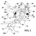
- FIG. 1is an isometric, exploded view of a preferred embodiment of the Rescue Hook of the invention.
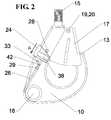
- FIG. 2is a front view of a preferred embodiment of the Rescue Hook with the gate closed and the latch in the locked position.
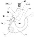
- FIG. 3is a front view of a preferred embodiment of the Rescue Hook with the latch in the unlocked position and the gate open.
- FIG. 3 ais a front view of a preferred embodiment of the Rescue Hook with the latch in the unlocked position, the gate closed, and showing a load sling in place.
- FIG. 4is an isometric view of the body of a preferred embodiment of the Rescue Hook.
- FIG. 5is an isometric view of a ball-detent plunger (3 ⁇ scale of FIG. 4 ).
- FIG. 6is an isometric view of a latch (2 ⁇ scale of FIG. 4 ).
- the Rescue Hookhas a hook body 10 with a curved, lower inside edge 11 and an opening (hereafter referred to as gap) 12 between the hook tip 13 and the upper inside edge 14 of said hook body.
- a threaded attachment stem 15is located at the top of said hook body 10 and serves as an attachment to mate with a hoisting apparatus, connecting swivel or other connecting device.
- the particular means by which the Rescue Hook is mated with a line connecting it to a hoistis not part of the invention, however. As persons skilled in the art will recognize, other attachment methods would also be possible.
- a multi-purpose hole 16 located at the bottom of the hookcan serve as an attachment location for an accessory or safety line.
- Gap 12is bridged by a triangular-shaped gate 17 , which gate is pivotally attached to said hook body 10 by means of a rivet style fastener 18 or similar fastening device.
- gate 17comprises two essentially triangular plates 17 a and 17 b which are joined on one side by side 22 a .
- Fastener 18passes through holes 19 bored through two opposing sides 17 a and 17 b of gate 17 at its upper end and also passes through holes 20 bored through two ears 21 that extend from hook body 10 .
- a cut-out 22 in the lower portion of the side 22 a of gate 17allows gate 17 to cover a portion of hook tip 13 .
- the upper edge of cut-out 22i.e., the lower edge of side 22 a ) makes contact with hook tip 13 and serves to limit the rotation of gate 17 away from hook body 10 .
- a torsion spring 23is located between ears 21 and serves to bias gate 17 toward hook tip 13 .
- torsion spring 23rests between ears 21 ; fastener 18 passes through the coil portion of torsion spring 23 .
- One distal end 23 a of torsion spring 23rests against the inside face of side 22 a of gate 17 , while the other distal end 23 b of torsion spring 23 rests against the portion of hook body 10 between ears 21 .
- Gate 17has two operating positions: closed and open. In the closed position (as shown in FIG. 2 with side 22 a shown with hidden lines), the upper edge of cut-out 22 is held against hook tip 13 by the force of torsion spring 23 . In the open position (as shown in FIG. 3 ), gate 17 is rotated toward the main portion of hook body 10 .
- this inventionincorporates a safety locking mechanism in the form of a latch 24 .
- Said latch 24is in the form of a saddle that is slidably attached to said hook body 10 by means of two protruding rails 25 on the opposing inside faces of latch 24 .
- Rails 25mate with two grooves 26 , which grooves are cut into opposing sides of hook body 10 and are parallel with the upper outside edge 27 of hook body 10 .
- upper stop-pin 28is placed through a hole 30 bored through hook body 10 at the upper end of grooves 26 .
- Lower stop-pin 29is placed through a hole 31 bored through hook body 10 at a point along grooves 26 approximately 1.25 inches below the centerline of upper stop-pin 28 .
- the ends of stop pins 28 and 29are flush with the sides of hook body 10 , but form obstructions within grooves 26 that restrict the extent to which latch 24 may slide in said grooves.
- latch 24is held in two distinct positions with the aid of a threaded, upper ball-detent plunger 32 and a threaded, lower ball-detent plunger 33 .
- a threaded, upper ball-detent plunger 32 and a threaded, lower ball-detent plunger 33are well known in the art.
- Such ball-detent plungersan outer view of which is shown in FIG. 5, generally comprise a threaded outer body portion encasing a spring and ball, with the ball biased by the spring through an opening in one end of the ball-detent plunger.
- Such a ball-detent plungeris available from McMaster-Carr Supply Company, part no. 340A95.
- Upper ball-detent plunger 32is threaded into a tapped hole 34 bored through hook body 10 in an area between grooves 26 and upper outside edge 27 of hook body 10 .
- lower ball-detent plunger 33is threaded into a tapped hole 35 bored through said hook body 10 approximately 0.45 inches below the centerline of upper ball-detent plunger hole 34 in a direction parallel to grooves 26 .
- a small indentation 36 on the inside face of said latch 24is designed to mate with the spring-loaded ball 37 of ball-detent plungers 32 and 33 .
- latch 24When indentation 36 is mated with said spring-loaded ball 37 of upper ball-detent plunger 32 , latch 24 is in the locked position (as shown in FIG. 2 ). In this position, the lower edges of latch 24 prevent gate 17 from rotating to the open position.
- indentation 36is mated with the spring-loaded ball 37 of lower ball-detent plunger 33 , latch 24 is in the unlocked position (as shown in FIG. 3 ). In this position, gate 17 is free to rotate between the open and closed positions.
- the spring-loaded force of the balls 37 of ball-detent plungers 32 and 33serve to retain latch 24 in the locked and unlocked positions, respectively. Said spring forces can be overcome, however, by exerting a moderate sliding force on latch 24 in directions A (FIG. 2) and B (FIG. 3 a ). Ease of moving latch 24 from the locked position to the unlocked position and vice versa is enhanced by the addition of grippers 38 formed into the sides of latch 24 .
- the configuration of a sliding latchallows an operator to lock or unlock the Rescue Hook, even if the operator's fingers are cold and/or numb, by moving latch 24 with the palm of the hand.
- Indentation 36 on the inside face of latch 24can be created by boring a hole 39 through the opposite side of latch 24 and then using the tip of the drill to create indentation 36 in a procedure commonly referred to as “spot facing”. Hole 39 also allows access to ball-detent plungers 32 and 33 . This access allows the tension of the ball-detent plungers 32 and 33 to be adjusted while mated with indentation 36 .
- latch 24in its locked and unlocked positions, the use of ball-detent plungers being merely the preferred embodiment.
- a spring-loaded cam-type followercould be adapted to an inside portion of latch 24 and configured to rest in depressions formed on body 10 .
- this inventionfurther includes colored pins made from fiber-optic material, plastic or other suitable material, and that indicate whether latch 24 is in the locked or unlocked position.
- a red pin 40is placed through a hole 41 bored through hook body 10 inside said grooves 26 just below upper stop pin 28 .
- red pin 40is visible, indicating this position as unsafe.
- a green pin 42is placed through a hole 43 bored through hook body 10 inside grooves 26 just above lower stop pin 29 .
- green pin 42is visible, indicating this position as safe.
- the ends of both pins 40 and 42are flush with the bottoms of grooves 26 , thereby not interfering with the motion of latch 24 .
- Hook body 10 , gate 17 and latch 24can be made from any material or materials that will provide the strength and corrosion-resistance properties needed for a particular application. Possible materials include 15-5PH or 17-4PH stainless steel.
Landscapes
- Engineering & Computer Science (AREA)
- General Engineering & Computer Science (AREA)
- Mechanical Engineering (AREA)
- Emergency Lowering Means (AREA)
Abstract
Description
Claims (13)
Priority Applications (1)
| Application Number | Priority Date | Filing Date | Title |
|---|---|---|---|
| US09/679,278US6363589B1 (en) | 2000-10-04 | 2000-10-04 | Rescue hook with safety locking mechanism |
Applications Claiming Priority (1)
| Application Number | Priority Date | Filing Date | Title |
|---|---|---|---|
| US09/679,278US6363589B1 (en) | 2000-10-04 | 2000-10-04 | Rescue hook with safety locking mechanism |
Publications (1)
| Publication Number | Publication Date |
|---|---|
| US6363589B1true US6363589B1 (en) | 2002-04-02 |
Family
ID=24726267
Family Applications (1)
| Application Number | Title | Priority Date | Filing Date |
|---|---|---|---|
| US09/679,278Expired - Fee RelatedUS6363589B1 (en) | 2000-10-04 | 2000-10-04 | Rescue hook with safety locking mechanism |
Country Status (1)
| Country | Link |
|---|---|
| US (1) | US6363589B1 (en) |
Cited By (16)
| Publication number | Priority date | Publication date | Assignee | Title |
|---|---|---|---|---|
| US6718601B1 (en) | 2001-08-23 | 2004-04-13 | Gary E. Choate | Tie back snap |
| US20050013653A1 (en)* | 2003-07-16 | 2005-01-20 | Stephen Eun Chin | Self-closing ring binder |
| US7636990B1 (en) | 2008-03-25 | 2009-12-29 | Gary E Choate | Snap hook with hoop-loaded gate |
| USD626908S1 (en)* | 2009-11-09 | 2010-11-09 | Aerial Machine & Tool Corp. | Helicopter hook |
| US8015676B1 (en) | 2008-03-25 | 2011-09-13 | Reliance Industries, Llc | Snap hook with interlocking gate |
| WO2013055194A3 (en)* | 2011-10-14 | 2013-06-06 | Sharoiko Mikhail Mikhailovich | Fastening device (variants) |
| WO2014040114A1 (en)* | 2012-09-11 | 2014-03-20 | Capital Safety Group (Australia) Pty Limited | Improved snap hook |
| CN108147303A (en)* | 2017-12-13 | 2018-06-12 | 国网湖北省电力公司宜昌供电公司 | A kind of fixed pulley |
| TWI627898B (en)* | 2013-08-09 | 2018-07-01 | 日商阿斯安寵股份有限公司 | Animal connector |
| USD843814S1 (en) | 2018-01-26 | 2019-03-26 | Aerial Machine & Tool Corporation | Hook |
| USRE47349E1 (en)* | 2008-01-24 | 2019-04-16 | Nautilus Rigging Llp | Hook |
| USD867863S1 (en)* | 2018-08-14 | 2019-11-26 | 152310 Canada | Secure rod hook |
| USD867862S1 (en)* | 2018-08-14 | 2019-11-26 | 152310 Canada | Rod hook |
| WO2021108856A1 (en) | 2019-12-05 | 2021-06-10 | David Owen | A connection point assembly for a patient lifter spreader bar with a visual indicator indicative of a latch position thereof |
| USD945252S1 (en) | 2019-12-18 | 2022-03-08 | TruBlue LLC | Carabiner |
| US11293478B2 (en)* | 2019-11-05 | 2022-04-05 | TruBlue LLC | Carabiner |
Citations (20)
| Publication number | Priority date | Publication date | Assignee | Title |
|---|---|---|---|---|
| US939727A (en)* | 1909-10-04 | 1909-11-09 | Matti Maki | Snap-hook. |
| US1347369A (en)* | 1919-05-03 | 1920-07-20 | Andrew E Young | Draft-hook |
| US1521811A (en)* | 1923-08-06 | 1925-01-06 | Carl W Hartbauer | Snap hook |
| US1667957A (en) | 1926-10-06 | 1928-05-01 | D & B Pump And Supply Company | Hoisting hook |
| US2706318A (en) | 1953-10-05 | 1955-04-19 | Coffing Hoist Company Inc | Safety hook |
| US2872717A (en)* | 1955-01-10 | 1959-02-10 | Leon P Kelley | Safety hook |
| US3194598A (en) | 1963-09-18 | 1965-07-13 | Martin N Goldfuss | Helicopter rescue hook |
| US3940173A (en)* | 1975-02-10 | 1976-02-24 | Columbus Mckinnon Corporation | Safety hook |
| US4320561A (en) | 1978-12-16 | 1982-03-23 | Eisen- Und Drahtwerk Erlau Aktiengesellschaft | Hook, especially safety load hook |
| US4440432A (en)* | 1982-02-22 | 1984-04-03 | The Crosby Group, Inc. | Self-locking, quick release, latched hook |
| US4492386A (en)* | 1983-06-10 | 1985-01-08 | Roberts Hardy G | Trailer safety device |
| US4528729A (en) | 1983-08-26 | 1985-07-16 | Rose Manufacturing Company | Locking snap hook |
| US4539732A (en) | 1984-01-30 | 1985-09-10 | D B Industries, Inc. | Double locking safety snap |
| US4977647A (en) | 1989-10-27 | 1990-12-18 | D.B. Industries, Inc. | Double locking snap hook |
| US5257441A (en)* | 1992-09-02 | 1993-11-02 | United States Forgecraft Corp. | Triple locking snap hook |
| US5463798A (en)* | 1992-11-02 | 1995-11-07 | Wurzer; Franz | Self-locking carabiner |
| US5577304A (en)* | 1994-08-12 | 1996-11-26 | Etablissements Ludger Simond Societe Anonyme | Karabiner with dynamic locking feature |
| USD389983S (en) | 1997-02-19 | 1998-01-27 | Maness Samuel G | Locking hoist hook |
| US5735025A (en) | 1996-09-25 | 1998-04-07 | United States Forgecraft Corporation | Ergonomic recessed release safety hook |
| US5896630A (en) | 1998-02-03 | 1999-04-27 | Haun Drop Forge Co., Ltd. | Self locking snap hook |
- 2000
- 2000-10-04USUS09/679,278patent/US6363589B1/ennot_activeExpired - Fee Related
Patent Citations (20)
| Publication number | Priority date | Publication date | Assignee | Title |
|---|---|---|---|---|
| US939727A (en)* | 1909-10-04 | 1909-11-09 | Matti Maki | Snap-hook. |
| US1347369A (en)* | 1919-05-03 | 1920-07-20 | Andrew E Young | Draft-hook |
| US1521811A (en)* | 1923-08-06 | 1925-01-06 | Carl W Hartbauer | Snap hook |
| US1667957A (en) | 1926-10-06 | 1928-05-01 | D & B Pump And Supply Company | Hoisting hook |
| US2706318A (en) | 1953-10-05 | 1955-04-19 | Coffing Hoist Company Inc | Safety hook |
| US2872717A (en)* | 1955-01-10 | 1959-02-10 | Leon P Kelley | Safety hook |
| US3194598A (en) | 1963-09-18 | 1965-07-13 | Martin N Goldfuss | Helicopter rescue hook |
| US3940173A (en)* | 1975-02-10 | 1976-02-24 | Columbus Mckinnon Corporation | Safety hook |
| US4320561A (en) | 1978-12-16 | 1982-03-23 | Eisen- Und Drahtwerk Erlau Aktiengesellschaft | Hook, especially safety load hook |
| US4440432A (en)* | 1982-02-22 | 1984-04-03 | The Crosby Group, Inc. | Self-locking, quick release, latched hook |
| US4492386A (en)* | 1983-06-10 | 1985-01-08 | Roberts Hardy G | Trailer safety device |
| US4528729A (en) | 1983-08-26 | 1985-07-16 | Rose Manufacturing Company | Locking snap hook |
| US4539732A (en) | 1984-01-30 | 1985-09-10 | D B Industries, Inc. | Double locking safety snap |
| US4977647A (en) | 1989-10-27 | 1990-12-18 | D.B. Industries, Inc. | Double locking snap hook |
| US5257441A (en)* | 1992-09-02 | 1993-11-02 | United States Forgecraft Corp. | Triple locking snap hook |
| US5463798A (en)* | 1992-11-02 | 1995-11-07 | Wurzer; Franz | Self-locking carabiner |
| US5577304A (en)* | 1994-08-12 | 1996-11-26 | Etablissements Ludger Simond Societe Anonyme | Karabiner with dynamic locking feature |
| US5735025A (en) | 1996-09-25 | 1998-04-07 | United States Forgecraft Corporation | Ergonomic recessed release safety hook |
| USD389983S (en) | 1997-02-19 | 1998-01-27 | Maness Samuel G | Locking hoist hook |
| US5896630A (en) | 1998-02-03 | 1999-04-27 | Haun Drop Forge Co., Ltd. | Self locking snap hook |
Non-Patent Citations (2)
| Title |
|---|
| 10 pages from Lifesaving Systems Corp. catalog. |
| 11 printouts of Lifesaving Systems Corp. web. pages. |
Cited By (24)
| Publication number | Priority date | Publication date | Assignee | Title |
|---|---|---|---|---|
| US6718601B1 (en) | 2001-08-23 | 2004-04-13 | Gary E. Choate | Tie back snap |
| USRE44077E1 (en)* | 2001-08-23 | 2013-03-19 | Reliance Industries Llc | Tie back snap |
| US20050013653A1 (en)* | 2003-07-16 | 2005-01-20 | Stephen Eun Chin | Self-closing ring binder |
| USRE47349E1 (en)* | 2008-01-24 | 2019-04-16 | Nautilus Rigging Llp | Hook |
| US7636990B1 (en) | 2008-03-25 | 2009-12-29 | Gary E Choate | Snap hook with hoop-loaded gate |
| US8015676B1 (en) | 2008-03-25 | 2011-09-13 | Reliance Industries, Llc | Snap hook with interlocking gate |
| USD626908S1 (en)* | 2009-11-09 | 2010-11-09 | Aerial Machine & Tool Corp. | Helicopter hook |
| WO2013055194A3 (en)* | 2011-10-14 | 2013-06-06 | Sharoiko Mikhail Mikhailovich | Fastening device (variants) |
| US20150240861A1 (en)* | 2012-09-11 | 2015-08-27 | Capital Safety Group (Australia) Pty Limited | Snap hook |
| WO2014040114A1 (en)* | 2012-09-11 | 2014-03-20 | Capital Safety Group (Australia) Pty Limited | Improved snap hook |
| TWI627898B (en)* | 2013-08-09 | 2018-07-01 | 日商阿斯安寵股份有限公司 | Animal connector |
| US10058075B2 (en) | 2013-08-09 | 2018-08-28 | Earth Pet Co., Ltd. | Connector for animal |
| CN108147303A (en)* | 2017-12-13 | 2018-06-12 | 国网湖北省电力公司宜昌供电公司 | A kind of fixed pulley |
| USD843814S1 (en) | 2018-01-26 | 2019-03-26 | Aerial Machine & Tool Corporation | Hook |
| USD863046S1 (en) | 2018-01-26 | 2019-10-15 | Aerial Machine & Tool Corporation | Hook |
| USD867863S1 (en)* | 2018-08-14 | 2019-11-26 | 152310 Canada | Secure rod hook |
| USD867862S1 (en)* | 2018-08-14 | 2019-11-26 | 152310 Canada | Rod hook |
| US11293478B2 (en)* | 2019-11-05 | 2022-04-05 | TruBlue LLC | Carabiner |
| US11686339B2 (en) | 2019-11-05 | 2023-06-27 | TruBlue LLC | Carabiner |
| WO2021108856A1 (en) | 2019-12-05 | 2021-06-10 | David Owen | A connection point assembly for a patient lifter spreader bar with a visual indicator indicative of a latch position thereof |
| CN115279321A (en)* | 2019-12-05 | 2022-11-01 | 大卫·欧文 | Attachment point assembly for a patient lifter extension bar with visual indicator to indicate its latched position |
| EP4054503A4 (en)* | 2019-12-05 | 2024-04-17 | David Owen | CONNECTION POINT ARRANGEMENT FOR A PATIENT LIFT SPREADER BAR WITH A VISUAL INDICATOR INDICATING A LOCKING POSITION |
| USD945252S1 (en) | 2019-12-18 | 2022-03-08 | TruBlue LLC | Carabiner |
| USD976683S1 (en) | 2019-12-18 | 2023-01-31 | TruBlue LLC | Carabiner |
Similar Documents
| Publication | Publication Date | Title |
|---|---|---|
| US6363589B1 (en) | Rescue hook with safety locking mechanism | |
| US5046881A (en) | Lockable pin and clevis | |
| US6360408B1 (en) | Hooked latch with ball lock sliding sleeve retainer | |
| US5384943A (en) | Snap-hook with self-locking roller | |
| EP1927767B1 (en) | Improved safety carabiner | |
| US7967353B2 (en) | Clevis type grab hook with safety latch | |
| US4977647A (en) | Double locking snap hook | |
| USRE47349E1 (en) | Hook | |
| US6601274B2 (en) | Static line snap | |
| US5896630A (en) | Self locking snap hook | |
| US3940173A (en) | Safety hook | |
| US4546523A (en) | Safety hook construction | |
| EP3844091B1 (en) | Double locking hook | |
| US4309052A (en) | Safety hook | |
| AU2016393022B2 (en) | Safety hook | |
| US5361464A (en) | Double action snap hook | |
| US20120042487A1 (en) | Double locking snap hook device background of the invention | |
| US6898829B2 (en) | Coupling device | |
| US11905148B2 (en) | Snatch block with slide-open spring-biased cheek, dual-plunger lock release, and integral swivel stud | |
| US3003214A (en) | Safety hook | |
| US20020073520A1 (en) | karabiners | |
| GB2387617A (en) | A karabiner | |
| GB2077838A (en) | Safety clips for harnesses | |
| US4632226A (en) | Anti-falling device with rapid introduction and withdrawal of the cord in any position of this latter | |
| WO2007071896A1 (en) | Hook |
Legal Events
| Date | Code | Title | Description |
|---|---|---|---|
| AS | Assignment | Owner name:AERIAL MACHINE & TOOL CORPORATION, VIRGINIA Free format text:INVALID RECORDING;ASSIGNOR:MARCACCIO, JOHN D.;REEL/FRAME:011193/0546 Effective date:20001009 | |
| AS | Assignment | Owner name:AERIAL MACHINE & TOOL CORPORATION A VA. CORP., Free format text:(ASSIGNMENT OF ASSIGNOR'S INTEREST) RE-RECORD TO CORRECT THE RECORDATION DATE OF 10/09/2000 TO 10/19/2000, PREVIOUSLY RECORDED ON REEL 11193 FRAME 0546.;ASSIGNOR:MARCACCIO, JOHN D.;REEL/FRAME:011256/0615 Effective date:20001009 Owner name:AERIAL MACHINE & TOOL CORPORATION, A VA. CORP., V Free format text:ASSIGNMENT OF ASSIGNORS INTEREST;ASSIGNOR:CALLOWAY, CHARLES H.;REEL/FRAME:011193/0541 Effective date:20001009 | |
| CC | Certificate of correction | ||
| FPAY | Fee payment | Year of fee payment:4 | |
| FEPP | Fee payment procedure | Free format text:PAT HOLDER NO LONGER CLAIMS SMALL ENTITY STATUS, ENTITY STATUS SET TO UNDISCOUNTED (ORIGINAL EVENT CODE: STOL); ENTITY STATUS OF PATENT OWNER: LARGE ENTITY | |
| FPAY | Fee payment | Year of fee payment:8 | |
| REMI | Maintenance fee reminder mailed | ||
| LAPS | Lapse for failure to pay maintenance fees | ||
| STCH | Information on status: patent discontinuation | Free format text:PATENT EXPIRED DUE TO NONPAYMENT OF MAINTENANCE FEES UNDER 37 CFR 1.362 | |
| FP | Lapsed due to failure to pay maintenance fee | Effective date:20140402 |