US6363273B1 - Introducer element and method of using same - Google Patents
Introducer element and method of using sameDownload PDFInfo
- Publication number
- US6363273B1 US6363273B1US09/470,062US47006299AUS6363273B1US 6363273 B1US6363273 B1US 6363273B1US 47006299 AUS47006299 AUS 47006299AUS 6363273 B1US6363273 B1US 6363273B1
- Authority
- US
- United States
- Prior art keywords
- lumen
- peel
- introducer element
- tubing
- proximal end
- Prior art date
- Legal status (The legal status is an assumption and is not a legal conclusion. Google has not performed a legal analysis and makes no representation as to the accuracy of the status listed.)
- Expired - Lifetime
Links
Images


Classifications
- A—HUMAN NECESSITIES
- A61—MEDICAL OR VETERINARY SCIENCE; HYGIENE
- A61M—DEVICES FOR INTRODUCING MEDIA INTO, OR ONTO, THE BODY; DEVICES FOR TRANSDUCING BODY MEDIA OR FOR TAKING MEDIA FROM THE BODY; DEVICES FOR PRODUCING OR ENDING SLEEP OR STUPOR
- A61M25/00—Catheters; Hollow probes
- A61M25/01—Introducing, guiding, advancing, emplacing or holding catheters
- A61M25/06—Body-piercing guide needles or the like
- A61M25/0662—Guide tubes
- A61M25/0668—Guide tubes splittable, tear apart
- A—HUMAN NECESSITIES
- A61—MEDICAL OR VETERINARY SCIENCE; HYGIENE
- A61B—DIAGNOSIS; SURGERY; IDENTIFICATION
- A61B5/00—Measuring for diagnostic purposes; Identification of persons
- A61B5/145—Measuring characteristics of blood in vivo, e.g. gas concentration or pH-value ; Measuring characteristics of body fluids or tissues, e.g. interstitial fluid or cerebral tissue
- A61B5/1455—Measuring characteristics of blood in vivo, e.g. gas concentration or pH-value ; Measuring characteristics of body fluids or tissues, e.g. interstitial fluid or cerebral tissue using optical sensors, e.g. spectral photometrical oximeters
- A61B5/14551—Measuring characteristics of blood in vivo, e.g. gas concentration or pH-value ; Measuring characteristics of body fluids or tissues, e.g. interstitial fluid or cerebral tissue using optical sensors, e.g. spectral photometrical oximeters for measuring blood gases
- A61B5/14553—Measuring characteristics of blood in vivo, e.g. gas concentration or pH-value ; Measuring characteristics of body fluids or tissues, e.g. interstitial fluid or cerebral tissue using optical sensors, e.g. spectral photometrical oximeters for measuring blood gases specially adapted for cerebral tissue
- A—HUMAN NECESSITIES
- A61—MEDICAL OR VETERINARY SCIENCE; HYGIENE
- A61M—DEVICES FOR INTRODUCING MEDIA INTO, OR ONTO, THE BODY; DEVICES FOR TRANSDUCING BODY MEDIA OR FOR TAKING MEDIA FROM THE BODY; DEVICES FOR PRODUCING OR ENDING SLEEP OR STUPOR
- A61M2210/00—Anatomical parts of the body
- A61M2210/06—Head
- A61M2210/0693—Brain, cerebrum
Definitions
- the present inventionrelates to medical devices, particularly to an introducer element to assist in the placement of a medical device into a body, and more particularly to an introducer element to assist in the placement of a sensor into brain tissue.
- monitoring instrumentationMost medical patients require monitoring of one or more of their medical functions during hospitalization and/or during home-treatment. Chief among the concerns regarding the monitoring process is that the measurements obtained from monitoring instrumentation are as accurate as possible. In order to provide accurate measurements, however, the monitoring instrumentation must be placed at an exact location within the body, and the monitoring instrumentation must not migrate from this exact position during the monitoring process. Other concerns related to the monitoring process are that the monitoring instrumentation can be easily inserted and positioned without the need for numerous devices that could complicate the procedure, that the monitoring instrumentation is easily removable once in place, and that the entire monitoring process reduces trauma to the tissue of the patient as much as possible.
- the above concernsare especially relevant with regard to a sensor that is inserted into brain tissue in order to measure characteristics of the brain, such as O 2 , CO 2 , pH and temperature.
- These sensorstend to be flexible yet fragile, and thus have proven to be difficult to initially place within brain tissue without support and to assuredly secure at a desired depth within brain tissue.
- the present inventionprovides an introducer element. Although the invention is primarily shown and described as being used to effectuate the placement of a sensor into brain tissue, it is understood that the invention has other applications as well, such as to effectuate the placement of a medical device into other areas of the body.
- the introducer elementincludes a body that has a longitudinal axis and that is divided into first, second, third and fourth housing areas.
- the third housing areais connected to the first, second and fourth housing areas and is disposed between the first and fourth housing areas as well as the second and fourth housing areas.
- the first housing areaincludes at least a first lumen
- the second housing areaincludes at least a second lumen.
- a quantity of peel-away tubingis disposed within the second lumen, wherein at least a portion of the peel-away tubing is also located outside of the second lumen, and wherein the tubing has a slit defined therein.
- the first and second lumenare separate from each other in the first and second housing areas of the introducer element body but are merged to form a combined lumen within either the third or fourth housing area.
- the introducer elementalso includes a guide/splitting tube, which is generally disposed within the first lumen, and which passes through the slit defined within the quantity of peel-away tubing.
- the guide/splitting tubeprovides a path between the first lumen and the combined lumen.
- the combined lumenis also defined so as to be substantially internally lined by the quantity of peel away tubing.
- the first and fourth housing areas of the bodyare substantially coaxial with the longitudinal axis of the body, while the second housing area is offset from the longitudinal axis of the body.
- the introducer elementmay be used in conjunction with other equipment to insert a medical instrument, such as a sensor, into an area of the body, such as brain tissue.
- a medical instrumentsuch as a sensor
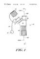
- FIG. 1is a side view of an introducer element in accordance with the present invention
- FIG. 2is a sectional view of the introducer element of FIG. 1 taken along line 2 — 2 of FIG. 1;
- FIG. 3is an enlarged view of a portion of the introducer element of FIG. 2;
- FIG. 4is side view of the introducer element of FIG. 1 with a stylet assembled therein and with a cap reversibly secured thereto;
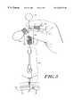
- FIG. 5is a side view of the introducer element of FIG. 1 wherein the stylet has been inserted through an entry facilitation element and into the body;
- FIG. 6is a side view of the introducer element of FIG. 1 being locked in position with respect to a body;
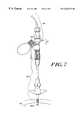
- FIG. 7is a side view of the introducer element of FIG. 1 wherein a medical instrument has been inserted into and through the introducer element, through an entry facilitation element, and into a body;
- FIG. 8is a side view of the medical instrument being locked in position with respect to the introducer element of FIG. 1;
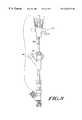
- FIG. 9is a side view of the introducer element of FIG. 1 during the removal of a quantity of peel-away tubing from the introducer element.
- FIG. 9Ais a view of the guide/splitting tube and peel away tubing within the introducer element of FIG. 9 during the removal of the quantity of peel away tubing from the introducer element.
- the introducer element 10has a body which includes first and second housing areas 12 , 14 , a third housing area 16 , and a fourth housing area 18 .
- the third housing area 16is connected to the first housing area 12 , the second housing area 14 and the fourth housing area 18 , and is disposed between the first and fourth housing areas as well as the second and fourth housing areas.
- the introducer element 10also has a longitudinal axis 100 , which has a proximal end 100 A and a distal end 100 B.
- a portion or end of an element that is described as being “proximal”is located closer to the proximal end 100 A of the longitudinal axis 100 of the introducer element, while a portion or end of an element that is described as being “distal” is located closer to the distal end 100 B of the longitudinal axis 100 .
- the first housing area 12 and the fourth housing area 18are both substantially coaxial with the longitudinal axis 100 of the body, while the second housing area 14 is offset from the longitudinal axis of the body.
- the body of the introducer element 10will generally have a substantially “Y” shape, wherein the second housing area 14 is offset from the longitudinal axis 100 by an angle of offset ( ⁇ ) in the range of about 20° to 75°.
- ⁇angle of offset
- the housing areas 12 , 14 , 16 , 18may have a wide range of positional relationships with respect to each other in addition to those described and depicted herein.
- the introducer element 10also includes a quantity of peel-away tubing 20 that is partially disposed within the element and to which a grasping element 21 is connected.
- the introducer element 10can also include a cap 22 that is adapted to reversibly fit onto the second housing area 14 . Both the peel-away tubing 20 and the cap 22 will be described in further detail below.
- the introducer element 10includes at least two lumens defined therewithin.
- a first lumen 24is defined within the first housing area 12
- a second lumen 26is defined within the second housing area 14 .
- These lumens 24 , 26are generally separated from each other in the first and second housing areas 12 , 14 , but merge within the either the third housing area 16 or the fourth housing area 18 of the introducer element 10 to form one combined lumen 28 .
- the quantity of peel-away tubing 20is partially disposed within the introducer element 10 . Specifically, a portion of the tubing 20 is located outside of the second housing area 14 , while the remainder of the tubing 20 is disposed within the introducer element 10 and beyond the fourth housing element 18 .
- the tubing 20may be made of a number of materials, including, but not limited to, polytetrafluoroethylene. Exemplary polytetrafluoroethylene tubing 20 is available from Zeus Industrial of Orangeburg, S.C. The advantages of Zeus polytetrafluoroethylene tubing will be discussed below.
- the first and second lumen 24 , 26 of the introducer element 10merge to form a combined lumen 28 .
- a guide/splitting tube 30is inserted into the first lumen 24 of the introducer element 10 and a slit 32 of the quantity of peel-away tubing 20 , thus splitting the peel-away tubing, as best shown in FIG. 3 .
- the guide/splitting tube 30has an expanded portion 31 that is sized and shaped to keep the guide/splitting tube from sliding into the combined lumen 28 and lies flush within the third housing area 16 (as shown in FIG. 2) to permit smooth transition of introduced objects.
- An internal guide 33(also shown in FIG. 2) prevents the slit 32 of the peel away tubing 20 from sliding off of the guide splitting tube 30 , and also ensures the continuity of the combined lumen 28 .
- the introducer element 10 described abovemay be used in conjunction with a process (illustrated in FIGS. 4-9) for inserting a sensor into brain tissue.
- a processillustrated in FIGS. 4-9 for inserting a sensor into brain tissue.
- FIGS. 4-9One of ordinary skill in the art will readily ascertain, however, that the below-described process can be utilized to assist in the insertion of other medical instruments into brain tissue and/or to assist in the insertion of a sensor or other medical instruments into other portions of the body.
- the introducer element 10is shown with a stylet 34 having been assembled through the first lumen 24 , the guide/splitting tube 30 , and the combined lumen 28 (each as shown in FIGS. 2 and 3) such that at least a distally-protruding portion 34 A of the stylet protrudes from the introducer element 10 .
- This portion 34 A of the stylet 34should protrude distally beyond the distal end of the quantity of peel-away tubing.
- the stylet 34 and peel away tubing 20may be enclosed by rigid protective tubing 36 in order to maintain the shape of the stylet and to provide protection to the thin walled peel away tubing.
- This protective tubing 36if included, is removed from the stylet 34 to prepare the stylet for insertion into a body as shown in FIG. 5 .
- the stylet 34 and peel-away tubing 20 lengthscan be varied prior to insertion to a predetermined depth in brain tissue by the surgeon. Once a distally-protruding portion 34 A (as shown in FIG. 5) of the stylet 34 and peel away tubing 20 are placed at a predetermined depth within brain tissue 40 (also as shown in FIG. 5 ), the stylet is secured with, for example, a clamp 42 such that the position of the stylet is maintained.
- FIG. 5depicts the introducer element 10 and stylet 34 having been inserted through an entry facilitation element 38 and into brain tissue 40 .
- the entry facilitation element 38provides a continuous pathway between the introducer element 10 and the brain tissue 40 to assist in the insertion of one or more medical instruments into the brain tissue.
- the placement, purpose and specific type of entry facilitation element 38 used in conjunction with the processmay vary greatly depending on, for example, the portion of the body into which the entry facilitation element is to provide a pathway.
- An exemplary entry facilitation element 38is a skull bolt that has been threaded into the skull to reach brain tissue 40 as shown in FIG. 5 .
- the introducer element 10is locked in place with respect to the entry facilitation element 38 .
- thisis done by grasping the introducer element 10 and rotating a fitting 44 in the direction shown by the arrow in FIG. 6 .
- both the stylet 34 and the clamp 42may be removed while still ensuring that the quantity of peel-away tubing remains unremoved from, and undisturbed with respect to, the brain tissue 40 .
- a medical instrument 46such as a sensor, is then inserted into the first housing area 12 of the element 10 .
- the sensor 46is connected to the introducer element 10 by the interlocking of a fitting 48 of the sensor with a fitting 50 of the first housing area 12 of the introducer element.
- the sensor 46is then carefully advanced into and through the first lumen 24 , the guide splitting tube 30 , the and the combined lumen 28 (each as shown in FIGS. 2 and 3 ), and then into and through the entry facilitation element 38 until a portion 46 A of the sensor reaches the predetermined depth measurement within the brain tissue 40 .
- the sensor 46generally will include an advancement lock 52 and a rear clamp 54 wherein, once the portion 46 A (as shown in FIG. 7) of the sensor has been advanced to the predetermined depth measurement within the brain tissue 40 (also as shown in FIG. 7 ), the advancement lock and rear clamp are both locked in order to maintain this predetermined depth measurement of the sensor.
- the sensor 46may optionally include numeric indicia 56 in order to assist in and/or verify that the portion 46 A of the sensor 46 has attained the predetermined depth measurement in the brain tissue.
- the quantity of peel-away tubingis removed from the introducer element 10 as shown in FIGS. 9 and 9A.
- the cap 22is removed from the second housing area 14 and then the grasping element 21 is pulled to withdraw the peel-away tubing 20 .
- the grasping element 21is pulled with enough force (at least approximately 0.04 pounds) such that the tubing splits at its slit, as best shown in FIG. 9 A.
- FIG. 9Adepicts the quantity of peel-away tubing 20 contained in the introducer element 10 of FIG. 9 while the tubing is being pulled in the direction indicated by the double arrows in FIG. 9 A.
- a rear portion 32 A of the slitwill be forced against the guide/splitting element and the slit will propagate.
- the slit 32will propagate axially as shown by the dashed lines in FIG. 9 A. This is because the Zeus Industrial tubing is manufactured such that its molecular chains are aligned.
- This molecular arrangementensures that if the tubing 20 includes a slit 32 , and the tubing is pulled such that the tubing begins to rip at this slit (as caused by the rear portion 32 A of the slit contacting the guide/splitting tube 30 ), the tubing will continue to split axially from that slit.
- the tubing 20 removal processcan likely occur without interruption and without the threat that the tubing will not completely, uniformly tear and/or will not be completely removed from the introducer element 10 .
- the pulling forceis continued until the tubing 20 is completely removed from the introducer element 10 . Once the tubing 20 is removed, the sensor can actively sense brain tissue 40 characteristics.
- the introducer element 10 and its componentsmay have a variety of shapes and sizes in accordance with the present invention.
- the combined lumen 28should be sized such that it may accept many different medical instruments, especially those that have a diameter of approximately 0.1 millimeters to approximately 2.5 millimeters.
- the quantity of peel-away tubing 20generally will have a length of between about 9.0 inches and about 10.5 inches, with a length of about 9.6 inches to 10.0 inches being preferred.
- the peel-away tubing 20also will generally have a wall thickness of between about 0.0127 millimeters and 0.0635 millimeters, with a wall thickness of about 0.0254 millimeters to 0.0508 millimeters being preferred.
- the tubing 20also has an inner diameter of about 0.381 millimeters to 0.889 millimeters, with an inner diameter of about 0.508 millimeters to about 0.762 millimeters being preferred.
- tubing diameterwill vary in relation to the diameter of the medical instrument to be inserted within the tubing.
Landscapes
- Health & Medical Sciences (AREA)
- Life Sciences & Earth Sciences (AREA)
- Biophysics (AREA)
- Pulmonology (AREA)
- Engineering & Computer Science (AREA)
- Anesthesiology (AREA)
- Biomedical Technology (AREA)
- Heart & Thoracic Surgery (AREA)
- Hematology (AREA)
- Animal Behavior & Ethology (AREA)
- General Health & Medical Sciences (AREA)
- Public Health (AREA)
- Veterinary Medicine (AREA)
- Media Introduction/Drainage Providing Device (AREA)
Abstract
Description
Claims (14)
Priority Applications (1)
| Application Number | Priority Date | Filing Date | Title |
|---|---|---|---|
| US09/470,062US6363273B1 (en) | 1999-12-22 | 1999-12-22 | Introducer element and method of using same |
Applications Claiming Priority (1)
| Application Number | Priority Date | Filing Date | Title |
|---|---|---|---|
| US09/470,062US6363273B1 (en) | 1999-12-22 | 1999-12-22 | Introducer element and method of using same |
Publications (1)
| Publication Number | Publication Date |
|---|---|
| US6363273B1true US6363273B1 (en) | 2002-03-26 |
Family
ID=23866119
Family Applications (1)
| Application Number | Title | Priority Date | Filing Date |
|---|---|---|---|
| US09/470,062Expired - LifetimeUS6363273B1 (en) | 1999-12-22 | 1999-12-22 | Introducer element and method of using same |
Country Status (1)
| Country | Link |
|---|---|
| US (1) | US6363273B1 (en) |
Cited By (30)
| Publication number | Priority date | Publication date | Assignee | Title |
|---|---|---|---|---|
| US6585665B1 (en)* | 1998-10-02 | 2003-07-01 | Diametrics Medical Limited | Probe |
| US20040073159A1 (en)* | 2002-08-08 | 2004-04-15 | Nelson David A. | Catheter system and method for administering regional anesthesia to a patient |
| WO2006065470A1 (en)* | 2004-12-17 | 2006-06-22 | Gore Enterprise Holdings, Inc. | Delivery system |
| US7402754B2 (en) | 2003-04-30 | 2008-07-22 | Kirwan Surgical Products, Inc. | Integral electrically conducting cord and lumen |
| US20080183175A1 (en)* | 2007-01-26 | 2008-07-31 | Laurimed Llc | Styli used to position device for carrying out selective discectomy |
| US20080188827A1 (en)* | 2007-02-01 | 2008-08-07 | Laurimed, Llc | Methods and devices for treating tissue |
| US20090093850A1 (en)* | 2007-10-05 | 2009-04-09 | Tyco Healthcare Group Lp | Expanding seal anchor for single incision surgery |
| US7553290B1 (en)* | 1999-06-04 | 2009-06-30 | Medtronic Ps Medical, Inc. | Subdural evacuating port aspiration system |
| US20090177143A1 (en)* | 2007-11-21 | 2009-07-09 | Markle William H | Use of an equilibrium intravascular sensor to achieve tight glycemic control |
| US20090259126A1 (en)* | 2008-04-02 | 2009-10-15 | Laurimed, Llc | Methods and devices for delivering injections |
| US20090264719A1 (en)* | 2008-04-17 | 2009-10-22 | Glumetrics, Inc. | Sensor for percutaneous intravascular deployment without an indwelling cannula |
| US20110077477A1 (en)* | 2009-09-30 | 2011-03-31 | Glumetrics, Inc. | Sensors with thromboresistant coating |
| US20110106097A1 (en)* | 2009-11-03 | 2011-05-05 | Radi Medical Systems Ab | Introducer access assembly |
| US20110105866A1 (en)* | 2009-11-04 | 2011-05-05 | Glumetrics, Inc. | Optical sensor configuration for ratiometric correction of blood glucose measurement |
| US20110152658A1 (en)* | 2009-12-17 | 2011-06-23 | Glumetrics, Inc. | Identification of aberrant measurements of in vivo glucose concentration using temperature |
| US20120215071A1 (en)* | 2009-11-03 | 2012-08-23 | St. Jude Medical Systems Ab | Introducer access assembly |
| US20120253361A1 (en)* | 2009-10-26 | 2012-10-04 | Ortotip, Ltd. | Microdrive for Use in Stereotactic Surgery |
| US8292909B1 (en) | 2010-06-30 | 2012-10-23 | Laurimed, Llc | Devices and methods for cutting tissue |
| US20130204082A1 (en)* | 2012-02-06 | 2013-08-08 | Cook Medical Technologies Llc | Manifold having rotatable ports |
| US8657842B2 (en) | 2010-06-30 | 2014-02-25 | Laurimed, Llc | Devices and methods for cutting tissue |
| US8738107B2 (en) | 2007-05-10 | 2014-05-27 | Medtronic Minimed, Inc. | Equilibrium non-consuming fluorescence sensor for real time intravascular glucose measurement |
| US8815099B1 (en) | 2014-01-21 | 2014-08-26 | Laurimed, Llc | Devices and methods for filtering and/or collecting tissue |
| US8838195B2 (en) | 2007-02-06 | 2014-09-16 | Medtronic Minimed, Inc. | Optical systems and methods for ratiometric measurement of blood glucose concentration |
| US20150359999A1 (en)* | 2014-06-17 | 2015-12-17 | Kimberly-Clark Worldwide, Inc. | Needle Hub for Over-the-Needle Catheter |
| US9763731B2 (en) | 2012-02-10 | 2017-09-19 | Myromed, Llc | Vacuum powered rotary devices and methods |
| USD809136S1 (en) | 2014-09-17 | 2018-01-30 | Kirwan Surgical Products Llc | Electrical connector and irrigation connector for irrigation cord assembly |
| WO2020055586A1 (en)* | 2018-09-10 | 2020-03-19 | Becton, Dickinson And Company | Systems of facilitating instrument delivery to a catheter assembly |
| US11045634B2 (en) | 2017-11-06 | 2021-06-29 | Abiomed, Inc. | Peel away hemostasis valve |
| US11364363B2 (en) | 2016-12-08 | 2022-06-21 | Abiomed, Inc. | Overmold technique for peel-away introducer design |
| US11793977B2 (en) | 2018-05-16 | 2023-10-24 | Abiomed, Inc. | Peel-away sheath assembly |
Citations (79)
| Publication number | Priority date | Publication date | Assignee | Title |
|---|---|---|---|---|
| US3669094A (en) | 1970-07-06 | 1972-06-13 | Heyer Schulte Corp | Device and method for measuring intracranial pressure |
| US4186728A (en) | 1977-02-18 | 1980-02-05 | U.S. Philips Corporation | Apparatus for adapting a skull for the application of a pressure transducer |
| US4205675A (en) | 1978-06-15 | 1980-06-03 | Johnson & Johnson | Catheter placement unit with needle removal provision and method of use |
| US4224943A (en) | 1979-01-24 | 1980-09-30 | Sorenson Research Co., Inc. | Cannula and method for bidirectional blood flow |
| US4224699A (en) | 1977-05-23 | 1980-09-30 | Sulzer Brothers Limited | Cap-shaped endoprosthesis for a femoral head |
| US4270535A (en) | 1979-10-18 | 1981-06-02 | Hospal Medical Corp. | Double lumen catheters |
| US4304231A (en) | 1980-01-09 | 1981-12-08 | Sherwood Medical Industries, Inc. | Catheter with wire stylet |
| US4306562A (en) | 1978-12-01 | 1981-12-22 | Cook, Inc. | Tear apart cannula |
| US4354506A (en) | 1980-01-17 | 1982-10-19 | Naganokeiki Seisakujo Company, Ltd. | Intracranial pressure gauge |
| US4402685A (en) | 1979-06-30 | 1983-09-06 | Intermedicat Gmbh | Dividable catheter |
| US4412832A (en) | 1981-04-30 | 1983-11-01 | Baxter Travenol Laboratories, Inc. | Peelable catheter introduction device |
| US4468224A (en) | 1982-01-28 | 1984-08-28 | Advanced Cardiovascular Systems, Inc. | System and method for catheter placement in blood vessels of a human patient |
| US4572212A (en) | 1982-03-15 | 1986-02-25 | Paul L. Sweeney, Jr. | Subarachnoid bolts |
| US4581025A (en) | 1983-11-14 | 1986-04-08 | Cook Incorporated | Sheath |
| US4613324A (en) | 1985-06-17 | 1986-09-23 | Ghajar Jamshid B G | Method and apparatus for guiding catheter into ventricular system of human brain |
| US4629451A (en) | 1985-09-23 | 1986-12-16 | Victory Engineering Corp. | Stereotaxic array plug |
| US4646752A (en) | 1983-04-25 | 1987-03-03 | Swann Karl W | Adjustable intracranial pressure measuring screw |
| US4650473A (en) | 1985-04-15 | 1987-03-17 | Warner-Lambert Company | Suturing saddle |
| US4676782A (en) | 1984-09-21 | 1987-06-30 | Vitaphore Corporation | Positionable tissue interfacing device for the management of percutaneous conduits |
| US4781690A (en) | 1986-03-20 | 1988-11-01 | Terumo Kabushiki Kaisha | Guiding tube for medical instruments |
| US4795434A (en) | 1987-09-10 | 1989-01-03 | C. R. Bard, Inc. | Apparatus for positioning a sensor in vivo |
| US4805634A (en) | 1986-06-06 | 1989-02-21 | Hellige Gmbh | Adapter assembly for use with a cranial biosensor |
| US4808157A (en) | 1987-07-13 | 1989-02-28 | Neuro Delivery Technology, Inc. | Multi-lumen epidural-spinal needle |
| US4821716A (en) | 1987-09-04 | 1989-04-18 | Neurodynamics, Inc. | Method and apparatus for perpendicular perforation of the cranium |
| US4865593A (en) | 1987-06-25 | 1989-09-12 | Sherwood Medical Company | Splittable cannula |
| US4883468A (en) | 1987-04-08 | 1989-11-28 | Terumo Kabushiki Kaisha | Medical tool introduction cannula and method of manufacturing the same |
| US4903707A (en) | 1988-04-22 | 1990-02-27 | Camino Laboratories | Ventricular catheter assembly |
| US4931056A (en) | 1987-09-04 | 1990-06-05 | Neurodynamics, Inc. | Catheter guide apparatus for perpendicular insertion into a cranium orifice |
| US4993425A (en) | 1988-01-05 | 1991-02-19 | Hellige Gmbh | Adapter assembly for use with a cranial biosensor |
| US4998938A (en) | 1988-06-09 | 1991-03-12 | Neurodynamics, Inc. | Removable skull mounted work platform and method of assembling same |
| US5007902A (en) | 1988-03-09 | 1991-04-16 | B. Braun Melsungen Ag | Catheter set for plexus anesthesia |
| US5054497A (en) | 1990-02-21 | 1991-10-08 | Biomedical Monitors And Implants, Inc. | Cranial sensor attaching device and method for its use |
| US5104388A (en) | 1990-05-08 | 1992-04-14 | Fbk International Corporation | Membrane splittable tubing |
| US5112309A (en)* | 1990-07-25 | 1992-05-12 | Abbott Laboratories | Sensor delivery device |
| EP0485118A1 (en) | 1990-11-08 | 1992-05-13 | Puritan-Bennett Corporation | Intravascular blood parameter sensor apparatus |
| US5116345A (en) | 1990-11-28 | 1992-05-26 | Ohio Medical Instrument Co., Inc. | Stereotactically implanting an intracranial device |
| US5163911A (en)* | 1990-10-31 | 1992-11-17 | Baxter International Inc. | Over-the-wire catheter |
| US5168873A (en) | 1990-04-30 | 1992-12-08 | Medtronic, Inc. | Method and apparatus for fiber optic sensor insertion |
| US5190528A (en) | 1990-10-19 | 1993-03-02 | Boston University | Percutaneous transseptal left atrial cannulation system |
| US5207648A (en) | 1990-12-14 | 1993-05-04 | The Kendall Company | Multilumen catheter |
| US5219335A (en) | 1991-05-23 | 1993-06-15 | Scimed Life Systems, Inc. | Intravascular device such as introducer sheath or balloon catheter or the like and methods for use thereof |
| US5221263A (en) | 1992-07-30 | 1993-06-22 | Gesco International, Inc. | Catheter emplacement apparatus |
| US5228452A (en)* | 1992-02-19 | 1993-07-20 | Target Therapeutics Inc. | Proximal end fitting with an improved seal for use in a catheter guidewire assembly |
| US5236424A (en) | 1992-06-05 | 1993-08-17 | Cardiac Pathways Corporation | Catheter with retractable cannula for delivering a plurality of chemicals |
| US5250038A (en) | 1992-10-09 | 1993-10-05 | Cook Incorporated | Multiple lumen vascular access introducer sheath |
| US5250033A (en) | 1992-10-28 | 1993-10-05 | Interventional Thermodynamics, Inc. | Peel-away introducer sheath having proximal fitting |
| US5256149A (en) | 1992-02-14 | 1993-10-26 | Ethicon, Inc. | Trocar having transparent cannula and method of using |
| US5281204A (en) | 1989-12-26 | 1994-01-25 | Nissho Corporation | Device for forming an inserting hole and method of using and making the same |
| US5284138A (en) | 1991-07-09 | 1994-02-08 | C. R. Bard, Inc. | Apparatus and method for positioning a sensor away from the blood vessel wall |
| US5290241A (en)* | 1992-10-16 | 1994-03-01 | Danforth Biomedical, Incorporated | Rapid removal over-the-wire catheter |
| US5295968A (en) | 1992-08-19 | 1994-03-22 | Wilson-Cook Medical Inc. | Stylet wire assembly |
| US5306259A (en) | 1992-08-10 | 1994-04-26 | Cathco, Inc. | Vascular access needle having an extended length body |
| US5312355A (en) | 1991-07-09 | 1994-05-17 | H L Medical Inventions, Inc. | Splittable hemostatic valve and sheath and the method for using the same |
| US5312357A (en) | 1991-11-04 | 1994-05-17 | Drager Medical Electonic B.V. | Catheter |
| US5322513A (en)* | 1992-01-22 | 1994-06-21 | Baxter International Inc. | Easy-to-handle, self-guiding catheter stripper |
| US5328480A (en) | 1992-10-09 | 1994-07-12 | Cook Incorporated | Vascular wire guiode introducer and method of use |
| US5356388A (en) | 1992-09-22 | 1994-10-18 | Target Therapeutics, Inc. | Perfusion catheter system |
| US5357955A (en) | 1992-05-22 | 1994-10-25 | Puritan-Bennett Corporation | Reinforced catheter probe |
| US5380290A (en) | 1992-04-16 | 1995-01-10 | Pfizer Hospital Products Group, Inc. | Body access device |
| US5389077A (en) | 1993-03-03 | 1995-02-14 | Uresil Corporation | Minimally invasive body cavity penetrating instruments |
| US5395335A (en) | 1991-05-24 | 1995-03-07 | Jang; G. David | Universal mode vascular catheter system |
| US5407432A (en) | 1992-03-30 | 1995-04-18 | Pameda N.V. | Method of positioning a stent |
| US5409461A (en) | 1993-09-28 | 1995-04-25 | Becton Dickinson And Company | Catheter introducer assembly with needle shielding device |
| US5409469A (en) | 1993-11-04 | 1995-04-25 | Medtronic, Inc. | Introducer system having kink resistant splittable sheath |
| US5441481A (en) | 1994-05-27 | 1995-08-15 | Mishra; Pravin | Microdialysis probes and methods of use |
| US5522400A (en)* | 1994-11-23 | 1996-06-04 | Uresil Corp | Locking catheter system |
| US5542936A (en) | 1995-03-20 | 1996-08-06 | Razi; Dean M. | Sheath for introducing catheter |
| US5585013A (en) | 1995-04-07 | 1996-12-17 | Truty; Thomas J. | Electrode guide |
| US5599345A (en) | 1993-11-08 | 1997-02-04 | Zomed International, Inc. | RF treatment apparatus |
| US5651767A (en) | 1994-05-06 | 1997-07-29 | Alfred F. Mann Foundation For Scientific Research | Replaceable catheter system for physiological sensors, stimulating electrodes and/or implantable fluid delivery systems |
| US5654539A (en) | 1995-08-17 | 1997-08-05 | Vasamedics L.L.C. | Laser doppler optical sensor for use on a monitoring probe |
| US5687727A (en)* | 1995-05-01 | 1997-11-18 | Danforth Biomedical Incorporated | Catheter adaptor with slitting blade and improved manual control and method of use |
| WO1997042870A1 (en) | 1996-05-14 | 1997-11-20 | Camino Neurocare, Inc. | Expandable parenchymal bolt |
| US5728132A (en) | 1996-04-08 | 1998-03-17 | Tricardia, L.L.C. | Self-sealing vascular access device |
| US5779665A (en) | 1997-05-08 | 1998-07-14 | Minimed Inc. | Transdermal introducer assembly |
| US5858007A (en) | 1996-07-03 | 1999-01-12 | C. R. Bard, Inc. | Hemostatic catheter introducer |
| US5891100A (en) | 1995-01-25 | 1999-04-06 | Fleckenstein; Wolfgang | Securing device for brain scan probes |
| US5951518A (en) | 1997-10-31 | 1999-09-14 | Teleflex, Incorporated | Introducing device with flared sheath end |
| US5957912A (en) | 1998-04-16 | 1999-09-28 | Camino Neurocare, Inc. | Catheter having distal stylet opening and connector |
- 1999
- 1999-12-22USUS09/470,062patent/US6363273B1/ennot_activeExpired - Lifetime
Patent Citations (79)
| Publication number | Priority date | Publication date | Assignee | Title |
|---|---|---|---|---|
| US3669094A (en) | 1970-07-06 | 1972-06-13 | Heyer Schulte Corp | Device and method for measuring intracranial pressure |
| US4186728A (en) | 1977-02-18 | 1980-02-05 | U.S. Philips Corporation | Apparatus for adapting a skull for the application of a pressure transducer |
| US4224699A (en) | 1977-05-23 | 1980-09-30 | Sulzer Brothers Limited | Cap-shaped endoprosthesis for a femoral head |
| US4205675A (en) | 1978-06-15 | 1980-06-03 | Johnson & Johnson | Catheter placement unit with needle removal provision and method of use |
| US4306562A (en) | 1978-12-01 | 1981-12-22 | Cook, Inc. | Tear apart cannula |
| US4224943A (en) | 1979-01-24 | 1980-09-30 | Sorenson Research Co., Inc. | Cannula and method for bidirectional blood flow |
| US4402685A (en) | 1979-06-30 | 1983-09-06 | Intermedicat Gmbh | Dividable catheter |
| US4270535A (en) | 1979-10-18 | 1981-06-02 | Hospal Medical Corp. | Double lumen catheters |
| US4304231A (en) | 1980-01-09 | 1981-12-08 | Sherwood Medical Industries, Inc. | Catheter with wire stylet |
| US4354506A (en) | 1980-01-17 | 1982-10-19 | Naganokeiki Seisakujo Company, Ltd. | Intracranial pressure gauge |
| US4412832A (en) | 1981-04-30 | 1983-11-01 | Baxter Travenol Laboratories, Inc. | Peelable catheter introduction device |
| US4468224A (en) | 1982-01-28 | 1984-08-28 | Advanced Cardiovascular Systems, Inc. | System and method for catheter placement in blood vessels of a human patient |
| US4572212A (en) | 1982-03-15 | 1986-02-25 | Paul L. Sweeney, Jr. | Subarachnoid bolts |
| US4646752A (en) | 1983-04-25 | 1987-03-03 | Swann Karl W | Adjustable intracranial pressure measuring screw |
| US4581025A (en) | 1983-11-14 | 1986-04-08 | Cook Incorporated | Sheath |
| US4676782A (en) | 1984-09-21 | 1987-06-30 | Vitaphore Corporation | Positionable tissue interfacing device for the management of percutaneous conduits |
| US4650473A (en) | 1985-04-15 | 1987-03-17 | Warner-Lambert Company | Suturing saddle |
| US4613324A (en) | 1985-06-17 | 1986-09-23 | Ghajar Jamshid B G | Method and apparatus for guiding catheter into ventricular system of human brain |
| US4629451A (en) | 1985-09-23 | 1986-12-16 | Victory Engineering Corp. | Stereotaxic array plug |
| US4781690A (en) | 1986-03-20 | 1988-11-01 | Terumo Kabushiki Kaisha | Guiding tube for medical instruments |
| US4805634A (en) | 1986-06-06 | 1989-02-21 | Hellige Gmbh | Adapter assembly for use with a cranial biosensor |
| US4883468A (en) | 1987-04-08 | 1989-11-28 | Terumo Kabushiki Kaisha | Medical tool introduction cannula and method of manufacturing the same |
| US4865593A (en) | 1987-06-25 | 1989-09-12 | Sherwood Medical Company | Splittable cannula |
| US4808157A (en) | 1987-07-13 | 1989-02-28 | Neuro Delivery Technology, Inc. | Multi-lumen epidural-spinal needle |
| US4821716A (en) | 1987-09-04 | 1989-04-18 | Neurodynamics, Inc. | Method and apparatus for perpendicular perforation of the cranium |
| US4931056A (en) | 1987-09-04 | 1990-06-05 | Neurodynamics, Inc. | Catheter guide apparatus for perpendicular insertion into a cranium orifice |
| US4795434A (en) | 1987-09-10 | 1989-01-03 | C. R. Bard, Inc. | Apparatus for positioning a sensor in vivo |
| US4993425A (en) | 1988-01-05 | 1991-02-19 | Hellige Gmbh | Adapter assembly for use with a cranial biosensor |
| US5007902A (en) | 1988-03-09 | 1991-04-16 | B. Braun Melsungen Ag | Catheter set for plexus anesthesia |
| US4903707A (en) | 1988-04-22 | 1990-02-27 | Camino Laboratories | Ventricular catheter assembly |
| US4998938A (en) | 1988-06-09 | 1991-03-12 | Neurodynamics, Inc. | Removable skull mounted work platform and method of assembling same |
| US5281204A (en) | 1989-12-26 | 1994-01-25 | Nissho Corporation | Device for forming an inserting hole and method of using and making the same |
| US5054497A (en) | 1990-02-21 | 1991-10-08 | Biomedical Monitors And Implants, Inc. | Cranial sensor attaching device and method for its use |
| US5168873A (en) | 1990-04-30 | 1992-12-08 | Medtronic, Inc. | Method and apparatus for fiber optic sensor insertion |
| US5104388A (en) | 1990-05-08 | 1992-04-14 | Fbk International Corporation | Membrane splittable tubing |
| US5112309A (en)* | 1990-07-25 | 1992-05-12 | Abbott Laboratories | Sensor delivery device |
| US5190528A (en) | 1990-10-19 | 1993-03-02 | Boston University | Percutaneous transseptal left atrial cannulation system |
| US5163911A (en)* | 1990-10-31 | 1992-11-17 | Baxter International Inc. | Over-the-wire catheter |
| EP0485118A1 (en) | 1990-11-08 | 1992-05-13 | Puritan-Bennett Corporation | Intravascular blood parameter sensor apparatus |
| US5116345A (en) | 1990-11-28 | 1992-05-26 | Ohio Medical Instrument Co., Inc. | Stereotactically implanting an intracranial device |
| US5207648A (en) | 1990-12-14 | 1993-05-04 | The Kendall Company | Multilumen catheter |
| US5219335A (en) | 1991-05-23 | 1993-06-15 | Scimed Life Systems, Inc. | Intravascular device such as introducer sheath or balloon catheter or the like and methods for use thereof |
| US5395335A (en) | 1991-05-24 | 1995-03-07 | Jang; G. David | Universal mode vascular catheter system |
| US5312355A (en) | 1991-07-09 | 1994-05-17 | H L Medical Inventions, Inc. | Splittable hemostatic valve and sheath and the method for using the same |
| US5284138A (en) | 1991-07-09 | 1994-02-08 | C. R. Bard, Inc. | Apparatus and method for positioning a sensor away from the blood vessel wall |
| US5312357A (en) | 1991-11-04 | 1994-05-17 | Drager Medical Electonic B.V. | Catheter |
| US5322513A (en)* | 1992-01-22 | 1994-06-21 | Baxter International Inc. | Easy-to-handle, self-guiding catheter stripper |
| US5256149A (en) | 1992-02-14 | 1993-10-26 | Ethicon, Inc. | Trocar having transparent cannula and method of using |
| US5228452A (en)* | 1992-02-19 | 1993-07-20 | Target Therapeutics Inc. | Proximal end fitting with an improved seal for use in a catheter guidewire assembly |
| US5407432A (en) | 1992-03-30 | 1995-04-18 | Pameda N.V. | Method of positioning a stent |
| US5380290A (en) | 1992-04-16 | 1995-01-10 | Pfizer Hospital Products Group, Inc. | Body access device |
| US5357955A (en) | 1992-05-22 | 1994-10-25 | Puritan-Bennett Corporation | Reinforced catheter probe |
| US5236424A (en) | 1992-06-05 | 1993-08-17 | Cardiac Pathways Corporation | Catheter with retractable cannula for delivering a plurality of chemicals |
| US5221263A (en) | 1992-07-30 | 1993-06-22 | Gesco International, Inc. | Catheter emplacement apparatus |
| US5306259A (en) | 1992-08-10 | 1994-04-26 | Cathco, Inc. | Vascular access needle having an extended length body |
| US5295968A (en) | 1992-08-19 | 1994-03-22 | Wilson-Cook Medical Inc. | Stylet wire assembly |
| US5356388A (en) | 1992-09-22 | 1994-10-18 | Target Therapeutics, Inc. | Perfusion catheter system |
| US5328480A (en) | 1992-10-09 | 1994-07-12 | Cook Incorporated | Vascular wire guiode introducer and method of use |
| US5250038A (en) | 1992-10-09 | 1993-10-05 | Cook Incorporated | Multiple lumen vascular access introducer sheath |
| US5290241A (en)* | 1992-10-16 | 1994-03-01 | Danforth Biomedical, Incorporated | Rapid removal over-the-wire catheter |
| US5250033A (en) | 1992-10-28 | 1993-10-05 | Interventional Thermodynamics, Inc. | Peel-away introducer sheath having proximal fitting |
| US5389077A (en) | 1993-03-03 | 1995-02-14 | Uresil Corporation | Minimally invasive body cavity penetrating instruments |
| US5409461A (en) | 1993-09-28 | 1995-04-25 | Becton Dickinson And Company | Catheter introducer assembly with needle shielding device |
| US5409469A (en) | 1993-11-04 | 1995-04-25 | Medtronic, Inc. | Introducer system having kink resistant splittable sheath |
| US5599345A (en) | 1993-11-08 | 1997-02-04 | Zomed International, Inc. | RF treatment apparatus |
| US5651767A (en) | 1994-05-06 | 1997-07-29 | Alfred F. Mann Foundation For Scientific Research | Replaceable catheter system for physiological sensors, stimulating electrodes and/or implantable fluid delivery systems |
| US5441481A (en) | 1994-05-27 | 1995-08-15 | Mishra; Pravin | Microdialysis probes and methods of use |
| US5522400A (en)* | 1994-11-23 | 1996-06-04 | Uresil Corp | Locking catheter system |
| US5891100A (en) | 1995-01-25 | 1999-04-06 | Fleckenstein; Wolfgang | Securing device for brain scan probes |
| US5542936A (en) | 1995-03-20 | 1996-08-06 | Razi; Dean M. | Sheath for introducing catheter |
| US5585013A (en) | 1995-04-07 | 1996-12-17 | Truty; Thomas J. | Electrode guide |
| US5687727A (en)* | 1995-05-01 | 1997-11-18 | Danforth Biomedical Incorporated | Catheter adaptor with slitting blade and improved manual control and method of use |
| US5654539A (en) | 1995-08-17 | 1997-08-05 | Vasamedics L.L.C. | Laser doppler optical sensor for use on a monitoring probe |
| US5728132A (en) | 1996-04-08 | 1998-03-17 | Tricardia, L.L.C. | Self-sealing vascular access device |
| WO1997042870A1 (en) | 1996-05-14 | 1997-11-20 | Camino Neurocare, Inc. | Expandable parenchymal bolt |
| US5858007A (en) | 1996-07-03 | 1999-01-12 | C. R. Bard, Inc. | Hemostatic catheter introducer |
| US5779665A (en) | 1997-05-08 | 1998-07-14 | Minimed Inc. | Transdermal introducer assembly |
| US5951518A (en) | 1997-10-31 | 1999-09-14 | Teleflex, Incorporated | Introducing device with flared sheath end |
| US5957912A (en) | 1998-04-16 | 1999-09-28 | Camino Neurocare, Inc. | Catheter having distal stylet opening and connector |
Cited By (67)
| Publication number | Priority date | Publication date | Assignee | Title |
|---|---|---|---|---|
| US6585665B1 (en)* | 1998-10-02 | 2003-07-01 | Diametrics Medical Limited | Probe |
| US7553290B1 (en)* | 1999-06-04 | 2009-06-30 | Medtronic Ps Medical, Inc. | Subdural evacuating port aspiration system |
| US8343138B2 (en) | 1999-06-04 | 2013-01-01 | Medtronic Xomed, Inc. | Subdural evacuation port aspiration device |
| US7120487B2 (en)* | 2002-08-08 | 2006-10-10 | Nelson David A | Catheter system and method for administering regional anesthesia to a patient |
| US20040073159A1 (en)* | 2002-08-08 | 2004-04-15 | Nelson David A. | Catheter system and method for administering regional anesthesia to a patient |
| US7402754B2 (en) | 2003-04-30 | 2008-07-22 | Kirwan Surgical Products, Inc. | Integral electrically conducting cord and lumen |
| JP2008523895A (en)* | 2004-12-17 | 2008-07-10 | ゴア エンタープライズ ホールディングス,インコーポレイティド | Delivery system |
| US8162905B2 (en)* | 2004-12-17 | 2012-04-24 | W. L. Gore & Associates, Inc. | Delivery system |
| US20060135990A1 (en)* | 2004-12-17 | 2006-06-22 | Johnson Eric G | Delivery system |
| WO2006065470A1 (en)* | 2004-12-17 | 2006-06-22 | Gore Enterprise Holdings, Inc. | Delivery system |
| AU2005316958B2 (en)* | 2004-12-17 | 2010-03-25 | W. L. Gore & Associates, Inc. | Delivery system |
| US8414587B2 (en) | 2007-01-26 | 2013-04-09 | Laurimed, Llc | Styli used to position device for carrying out selective discetomy |
| US20080183175A1 (en)* | 2007-01-26 | 2008-07-31 | Laurimed Llc | Styli used to position device for carrying out selective discectomy |
| US20080183192A1 (en)* | 2007-01-26 | 2008-07-31 | Laurimed Llc | Contralateral insertion method to treat herniation with device using visualization components |
| US20080188827A1 (en)* | 2007-02-01 | 2008-08-07 | Laurimed, Llc | Methods and devices for treating tissue |
| US8088119B2 (en) | 2007-02-01 | 2012-01-03 | Laurimed, Llc | Methods and devices for treating tissue |
| US8838195B2 (en) | 2007-02-06 | 2014-09-16 | Medtronic Minimed, Inc. | Optical systems and methods for ratiometric measurement of blood glucose concentration |
| US9839378B2 (en) | 2007-02-06 | 2017-12-12 | Medtronic Minimed, Inc. | Optical systems and methods for ratiometric measurement of blood glucose concentration |
| US8738107B2 (en) | 2007-05-10 | 2014-05-27 | Medtronic Minimed, Inc. | Equilibrium non-consuming fluorescence sensor for real time intravascular glucose measurement |
| US9474518B2 (en) | 2007-10-05 | 2016-10-25 | Covidien Lp | Expanding seal anchor for single incision surgery |
| US8795326B2 (en) | 2007-10-05 | 2014-08-05 | Covidien Lp | Expanding seal anchor for single incision surgery |
| US20090093850A1 (en)* | 2007-10-05 | 2009-04-09 | Tyco Healthcare Group Lp | Expanding seal anchor for single incision surgery |
| US8979790B2 (en) | 2007-11-21 | 2015-03-17 | Medtronic Minimed, Inc. | Use of an equilibrium sensor to monitor glucose concentration |
| US8088097B2 (en) | 2007-11-21 | 2012-01-03 | Glumetrics, Inc. | Use of an equilibrium intravascular sensor to achieve tight glycemic control |
| US8535262B2 (en) | 2007-11-21 | 2013-09-17 | Glumetrics, Inc. | Use of an equilibrium intravascular sensor to achieve tight glycemic control |
| US20090177143A1 (en)* | 2007-11-21 | 2009-07-09 | Markle William H | Use of an equilibrium intravascular sensor to achieve tight glycemic control |
| US8277437B2 (en) | 2008-04-02 | 2012-10-02 | Laurimed, Llc | Method of accessing two lateral recesses |
| US20090259126A1 (en)* | 2008-04-02 | 2009-10-15 | Laurimed, Llc | Methods and devices for delivering injections |
| US8512245B2 (en) | 2008-04-17 | 2013-08-20 | Glumetrics, Inc. | Sensor for percutaneous intravascular deployment without an indwelling cannula |
| US20090264719A1 (en)* | 2008-04-17 | 2009-10-22 | Glumetrics, Inc. | Sensor for percutaneous intravascular deployment without an indwelling cannula |
| US20110077477A1 (en)* | 2009-09-30 | 2011-03-31 | Glumetrics, Inc. | Sensors with thromboresistant coating |
| US8715589B2 (en) | 2009-09-30 | 2014-05-06 | Medtronic Minimed, Inc. | Sensors with thromboresistant coating |
| US20120253361A1 (en)* | 2009-10-26 | 2012-10-04 | Ortotip, Ltd. | Microdrive for Use in Stereotactic Surgery |
| US8469944B2 (en)* | 2009-11-03 | 2013-06-25 | Radi Medical Systems Ab | Introducer access assembly |
| US20110106097A1 (en)* | 2009-11-03 | 2011-05-05 | Radi Medical Systems Ab | Introducer access assembly |
| US20120215071A1 (en)* | 2009-11-03 | 2012-08-23 | St. Jude Medical Systems Ab | Introducer access assembly |
| US8700115B2 (en) | 2009-11-04 | 2014-04-15 | Glumetrics, Inc. | Optical sensor configuration for ratiometric correction of glucose measurement |
| US8467843B2 (en) | 2009-11-04 | 2013-06-18 | Glumetrics, Inc. | Optical sensor configuration for ratiometric correction of blood glucose measurement |
| US20110105866A1 (en)* | 2009-11-04 | 2011-05-05 | Glumetrics, Inc. | Optical sensor configuration for ratiometric correction of blood glucose measurement |
| US20110152658A1 (en)* | 2009-12-17 | 2011-06-23 | Glumetrics, Inc. | Identification of aberrant measurements of in vivo glucose concentration using temperature |
| US8298254B2 (en) | 2010-06-30 | 2012-10-30 | Laurimed, Llc | Devices and methods for cutting and evacuating tissue |
| US8657842B2 (en) | 2010-06-30 | 2014-02-25 | Laurimed, Llc | Devices and methods for cutting tissue |
| US8840632B2 (en) | 2010-06-30 | 2014-09-23 | Laurimed, Llc | Devices and methods for cutting tissue |
| US8882793B2 (en) | 2010-06-30 | 2014-11-11 | Laurimed, Llc | Devices and methods for cutting tissue |
| US8292909B1 (en) | 2010-06-30 | 2012-10-23 | Laurimed, Llc | Devices and methods for cutting tissue |
| US8685052B2 (en) | 2010-06-30 | 2014-04-01 | Laurimed, Llc | Devices and methods for cutting tissue |
| US9532796B2 (en) | 2010-06-30 | 2017-01-03 | Myromed, Llc | Devices and methods for cutting tissue |
| US9889265B2 (en) | 2012-02-06 | 2018-02-13 | Cook Medical Technologies Llc | Manifold having rotatable ports |
| US20130204082A1 (en)* | 2012-02-06 | 2013-08-08 | Cook Medical Technologies Llc | Manifold having rotatable ports |
| US9597470B2 (en)* | 2012-02-06 | 2017-03-21 | Cook Medical Technologies Llc | Manifold having rotatable ports |
| US9763731B2 (en) | 2012-02-10 | 2017-09-19 | Myromed, Llc | Vacuum powered rotary devices and methods |
| US9770289B2 (en) | 2012-02-10 | 2017-09-26 | Myromed, Llc | Vacuum powered rotary devices and methods |
| US8815099B1 (en) | 2014-01-21 | 2014-08-26 | Laurimed, Llc | Devices and methods for filtering and/or collecting tissue |
| US20150359999A1 (en)* | 2014-06-17 | 2015-12-17 | Kimberly-Clark Worldwide, Inc. | Needle Hub for Over-the-Needle Catheter |
| US9867963B2 (en)* | 2014-06-17 | 2018-01-16 | Avent, Inc. | Needle hub for over-the-needle catheter |
| USD809136S1 (en) | 2014-09-17 | 2018-01-30 | Kirwan Surgical Products Llc | Electrical connector and irrigation connector for irrigation cord assembly |
| US11364363B2 (en) | 2016-12-08 | 2022-06-21 | Abiomed, Inc. | Overmold technique for peel-away introducer design |
| US12076497B2 (en) | 2016-12-08 | 2024-09-03 | Abiomed, Inc. | Overmold technique for peel-away introducer design |
| US11717640B2 (en) | 2016-12-08 | 2023-08-08 | Abiomed, Inc. | Overmold technique for peel-away introducer design |
| US11045634B2 (en) | 2017-11-06 | 2021-06-29 | Abiomed, Inc. | Peel away hemostasis valve |
| US11793977B2 (en) | 2018-05-16 | 2023-10-24 | Abiomed, Inc. | Peel-away sheath assembly |
| US11406810B2 (en) | 2018-09-10 | 2022-08-09 | Beeton, Dickinson and Company | Systems and methods of facilitating instrument delivery to a catheter assembly |
| JP2022500202A (en)* | 2018-09-10 | 2022-01-04 | ベクトン・ディキンソン・アンド・カンパニーBecton, Dickinson And Company | A system that facilitates the supply of instruments to the catheter assembly |
| KR20210057729A (en)* | 2018-09-10 | 2021-05-21 | 백톤 디킨슨 앤드 컴퍼니 | A system that facilitates delivery of instruments to the catheter assembly |
| WO2020055586A1 (en)* | 2018-09-10 | 2020-03-19 | Becton, Dickinson And Company | Systems of facilitating instrument delivery to a catheter assembly |
| AU2019340409B2 (en)* | 2018-09-10 | 2025-01-02 | Becton, Dickinson And Company | Systems of facilitating instrument delivery to a catheter assembly |
| US12350461B2 (en) | 2018-09-10 | 2025-07-08 | Becton, Dickinson And Company | Systems and methods of facilitating instrument delivery to a catheter assembly |
Similar Documents
| Publication | Publication Date | Title |
|---|---|---|
| US6363273B1 (en) | Introducer element and method of using same | |
| AU687774B2 (en) | Percutaneous tract measuring device | |
| US4675007A (en) | Coupling device for attachment to an end of a catheter | |
| US5667514A (en) | Device and method for inserting a flexible element into soft tissue | |
| US10555719B2 (en) | Ultrasound assisted needle puncture mechanism | |
| US4650472A (en) | Apparatus and method for effecting percutaneous catheterization of a blood vessel using a small gauge introducer needle | |
| US4423740A (en) | Slit catheter method for measuring interstitial pressure | |
| US6494860B2 (en) | Introducer with multiple sheaths and method of use therefor | |
| US20100228083A1 (en) | Slotted clear cannula | |
| US5378241A (en) | Anesthesia instrument | |
| US20030073934A1 (en) | Double slotted-cannula device and method of use | |
| US20050137527A1 (en) | Graduated sheath and dilator assembly | |
| US10149733B2 (en) | Tunnel gage | |
| US6663605B2 (en) | Removable protective cannula for use in surgery | |
| JPS6116750A (en) | Catheter introducing apparatus, assembly and method | |
| JP2015509006A (en) | Catheter having a removable cannula for piercing a body cavity, and a cannula for use with a catheter movable within the cannula | |
| US20060270988A1 (en) | Low profile introducer apparatus | |
| US6585665B1 (en) | Probe | |
| EP3979930B1 (en) | Microintroducer system | |
| US20080234605A1 (en) | Catheter Guide Wire | |
| US4692155A (en) | Catheter | |
| EP0280528A2 (en) | Catheter introducer |
Legal Events
| Date | Code | Title | Description |
|---|---|---|---|
| AS | Assignment | Owner name:CODMAN & SHURTLEFF, INC., MASSACHUSETTS Free format text:ASSIGNMENT OF ASSIGNORS INTEREST;ASSIGNORS:MASTRORIO, BROOKE W.;GORHAN, MICHAEL C.;BEARDSLEY, TIMOTHY A.;REEL/FRAME:010700/0580 Effective date:20000225 | |
| FEPP | Fee payment procedure | Free format text:PAYOR NUMBER ASSIGNED (ORIGINAL EVENT CODE: ASPN); ENTITY STATUS OF PATENT OWNER: LARGE ENTITY | |
| STCF | Information on status: patent grant | Free format text:PATENTED CASE | |
| FPAY | Fee payment | Year of fee payment:4 | |
| FPAY | Fee payment | Year of fee payment:8 | |
| FPAY | Fee payment | Year of fee payment:12 | |
| AS | Assignment | Owner name:DEPUY SPINE, LLC, MASSACHUSETTS Free format text:ASSIGNMENT OF ASSIGNORS INTEREST;ASSIGNOR:CODMAN & SHURTLEFF, INC.;REEL/FRAME:045058/0627 Effective date:20121230 | |
| AS | Assignment | Owner name:HAND INNOVATIONS LLC, FLORIDA Free format text:ASSIGNMENT OF ASSIGNORS INTEREST;ASSIGNOR:DEPUY SPINE, LLC;REEL/FRAME:045074/0943 Effective date:20121230 Owner name:DEPUY SYNTHES PRODUCTS, LLC, MASSACHUSETTS Free format text:CHANGE OF NAME;ASSIGNOR:HAND INNOVATIONS LLC;REEL/FRAME:045476/0712 Effective date:20121231 Owner name:DEPUY SYNTHES PRODUCTS, INC., INDIANA Free format text:CHANGE OF NAME;ASSIGNOR:DEPUY SYNTHES PRODUCTS, LLC;REEL/FRAME:045479/0763 Effective date:20141219 | |
| AS | Assignment | Owner name:INTEGRA LIFESCIENCES CORPORATION, NEW JERSEY Free format text:ASSIGNMENT OF ASSIGNORS INTEREST;ASSIGNOR:DEPUY SYNTHES PRODUCTS, INC.;REEL/FRAME:045180/0382 Effective date:20171002 |