US6363085B1 - Universal serial bus repeater - Google Patents
Universal serial bus repeaterDownload PDFInfo
- Publication number
- US6363085B1 US6363085B1US09/046,442US4644298AUS6363085B1US 6363085 B1US6363085 B1US 6363085B1US 4644298 AUS4644298 AUS 4644298AUS 6363085 B1US6363085 B1US 6363085B1
- Authority
- US
- United States
- Prior art keywords
- pair
- devices
- transceiver
- data
- speed
- Prior art date
- Legal status (The legal status is an assumption and is not a legal conclusion. Google has not performed a legal analysis and makes no representation as to the accuracy of the status listed.)
- Expired - Lifetime
Links
Images


Classifications
- G—PHYSICS
- G06—COMPUTING OR CALCULATING; COUNTING
- G06F—ELECTRIC DIGITAL DATA PROCESSING
- G06F13/00—Interconnection of, or transfer of information or other signals between, memories, input/output devices or central processing units
- G06F13/38—Information transfer, e.g. on bus
- G06F13/40—Bus structure
- G06F13/4004—Coupling between buses
- G06F13/4027—Coupling between buses using bus bridges
- G06F13/4045—Coupling between buses using bus bridges where the bus bridge performs an extender function
Definitions
- USBUniversal Serial Bus
- PC and telecom industry leadersthat bring plug and play of computer peripherals outside the box, eliminating the need to install cards into dedicated computer slots and reconfigure the system.
- Personal computers equipped with USBallow computer peripherals to be automatically configured as soon as they are physically attached—without the need to reboot or run setup.
- USBalso allows multiple devices—up to 127—to run simultaneously on a computer, with peripherals such as monitors and keyboards acting as additional plug-in sites, or hubs.
- the cable lengthis critical in maintaining the signal integrity and the protocol timing. Excessive cabling can cause a USB device not to function correctly or not be recognized by the host system. Device manufacturers are given the freedom to save cost by not building in an expensive overkill. Therefore, by just adding a passive extension cable the signal can be delayed or distorted to an amount that would cause the problem described.
- the inventionacts as a repeater. That is, it accepts the signal from one direction via a transceiver, then repeats the same signal out the other direction via another transceiver.
- the inventionalso complies with all USB protocol which includes sensing of a high-speed or low-speed device, going into the suspend mode, and detecting an end of packet.
- FIG. 1is block diagram of the invention.
- FIG. 2is block diagram of the interconnection between the two transceivers.
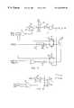
- FIG. 3is a schematic of the circuit that determines the speed type of the attached device on the downstream port and switches in the correct resistor on the upstream port which indicates the speed of the attached device.
- FIG. 4is a schematic of the circuit that detects which port is receiving data and enables the output of the transmitting transceiver.
- FIG. 5is a schematic of the circuit that detects an EOP (End of Packet) and disables the transceivers, as well as the circuit that disables the transceivers if the transceivers are enabled too long.
- EOPEnd of Packet
- FIG. 6is a schematic of the circuit that detects when the bus is in the suspend mode.
- the USBis a four-wire bus consisting of two differential signals, power (+5V), and ground. It is a master slave bus whereby the direction of the buffer's driving signals is controlled by the master and the timing for changing directions is set in the architecture of the wire protocol.
- the USBallows for high-speed devices (the bus running at 12 MHz) and low-speed devices (the bus running at 1.5 MHz.)
- a devicelets the host know its speed by the dc voltage on the bus during the idle time.
- a USB devicewill have its D+ signal pulled high through a 1.5K resistor if it is a high-speed device.
- a low-speed devicewill have its D ⁇ signal pulled high through a 1.5K resistor.
- SOPStart of Packet
- EOPEnd of Packet
- the SOPbegins with the bus changing from the idle state (called the J state) to its inverse state (the K state).
- An EOPbegins with the bus being driven to a single ended zero (SEO) state (both D+ and D ⁇ pulled low) and ends when the SEO is removed.
- SEOsingle ended zero
- the USB host systemsends out a short Start of Frame (SOF) packet every millisecond. When the SOF discontinues, all devices must go into the suspend state and limit the amount of power the device takes from the bus.
- a devicecan take the bus out of the suspend state by sending a resume signal upstream. This is done by placing a K state signal on the bus for a minimum of ten milliseconds.
- the USBresets the device by placing a SEO on the bus for a minimum of ten milliseconds.
- the connection to the hostis referred to as the upstream (US) port and the connection to the device as the downstream (DS) port.
- the cable connectors for upstream and downstream portsare different to assure that devices are not plugged in incorrectly.
- the upstream USB cable of the inventionis the extension of the cable length.
- the inventionreceives data from the USB upstream port and sends the same data downstream. It also receives data from the downstream port and sends the same data upstream.
- a reset signalis transmitted downstream, the invention assures that it continues downstream. If a resume signal is transmitted either upstream or downstream, the invention keeps the signal going in the correct direction.
- the inventiondetects that the bus is in its suspend state, the circuits go into a low power mode.
- FIG. 1shows the major components of the invention.
- the upstream USB cableplugs into the USB type ‘B’ connector 101 .
- the downstream USB device's cableplugs into the USB type ‘A’ connector 102 .
- the upstream signalsare received by the upstream transceiver 103 and sent downstream via transceiver 104 .
- the signal generated downstreamis received by transceiver 104 and transmitted by transceiver 103 upstream.
- the Speed Detector 109detects the device's speed from the differential signal when the bus is idle via a bus 114 and puts that state signal 113 to the upstream port. When data is not present on the bus, both transceivers 103 and 104 are in their high impedance receive mode.
- the Drive Detector 105senses received data via buses 110 and 111 .
- Drive Detector 105senses that the upstream transceiver 103 has received the initial bit of data by detecting an SOP signal.
- the drive of the downstream transceiver 104is enabled while keeping upstream transceiver 103 in its high impedance mode.
- the datawill continue to be received and transmitted until the EOP Detector 112 senses the EOP. At that time, the transceivers both resume their high impedance receive mode.
- the processis reversed.
- the Suspend Detector 107senses when no bus activity has occurred for more than three to eight SOF periods. When this occurs, the power reduced suspend state is entered by putting the transceivers 103 and 104 into their power reduced mode.
- signalsare identified by a mnemonic followed by a reference numeral designating on which line a signal occurs.
- Signal mnemonics preceded by US or DSare associated with upstream or downstream sides, respectively.
- DSFSEO 208is a downstream SEO signal on line 208 .
- FIG. 2shows the interconnection between the two transceivers 103 and 104 .
- the bus output lines DSD ⁇ 215 and DSD+ 216are driven by DSINP 206 , and generates an SE 0 by DSFSEO 208 only when the transceiver's outputs are enabled by DSOE 204 .
- the bus inputs DSD ⁇ 215 and DSD+ 216are sensed differentially to produce a received output DSREC 210 .
- the inputsare also used to detect a Single Ended Zero DSSEO 212 . The same is true for the upstream transceiver 103 .
- the Drive Detector 105enables the opposite output enable USOE 203 or DSOE 204 .
- the upstream received data USREC 209is the drive for the downstream input DSINP 206 .
- the downstream received data USREC 210is the drive for the upstream input DSINP 207 .
- the downstream received DSSEO 212is the drive for the upstream USFSEO 207 .
- the upstream received USSEO 211is the drive for the downstream DSFSEO 208 .
- SUSP 601is normally low. When the Suspend Detector 107 determines that the bus is in the suspend state, SUSP 601 goes high and puts the transceivers into their low current suspend state.
- FIG. 3is a schematic of a circuit that determines the speed type of the attached device on the downstream port and switches in the correct resistor on the upstream port.
- the HC 4066 'sare FET switches 301 , 303 , 305 , 307 are enabled when their control inputs 302 , 304 , 306 , 308 are high.
- DSD ⁇ 215 and DSD+ 216are low (0 volts).
- These signalsare inverted which causes both of the outputs of the NOR gates 31 and 32 to go low; these outputs disable FET switches 301 and 303 .
- This high voltagealso prevents the or gate 32 from enabling FET switch 303 .
- the SAMPLE-AND-HOLD outputenables switch 305 and 3.6V is placed on resistor 33 that pulls up USD+ 214 . This tells the host that a full speed device is attached. During bus activity DSD+ 214 will go low at times. The SAMPLE-AND-HOLD circuit will assure that the 3.6V is still coupled to resistor 33 . The SAMPLE-AND-HOLD time constant is chosen to assure that normal bus activity does not cause switch 305 to be disabled.
- DSD ⁇ 215is high and the circuit mirrors that of the full speed circuit.
- the signal FULLSP 301is high when a full speed device is attached and low when a low-speed device is attached. This signal is also used elsewhere.
- FIG. 4is a schematic of a circuit that detects which port is receiving data and enables the output of the transmitting transceiver.
- DSREC 210When the downstream port receives data while both ports are in their idle state, DSREC 210 will go from its J state to its K state. For full speed devices, the J state is high and the K state is low. The reverse is true for low-speed devices.
- the XOR gateinsures that the same signal will be produced regardless of a full speed or low-speed device.
- FULLSP 301 from FIG. 3is high when a full speed device is attached and low when a low-speed device is attached.
- the signal #EOPPULSE 402is generated by the EOP Detector 112 of FIG. 1 . It is normally high and pulses low for approximately twenty nanoseconds after the EOP is completed (see FIG. 5.)
- the input signal #EOPPULSE 402is ANDed with the reset output signal from the flip-flop 42 by and AND gate 43 whose output signal drives the clear input of the flip-flop 41 . This does two things. It does not allow USOE 203 to be enabled if the downstream port is transmitting, and it disables USOE 203 after the EOP is completed. When the invention enters the suspend mode, #SUSP 401 from FIG. 6 is low.
- D-flip-flop 41Since it is normally high and drives OR gate 44 output high, the D-flip-flop 41 is set.
- the signal to clock the flip-flop 44is chosen to be DSREC 210 instead of DSD ⁇ 215 since DSD ⁇ 215 could have glitches on it and DSREC 210 is the true received data.
- DSREC 210 and USREC 209are not enabled.
- DSD ⁇ 215 and USD ⁇ 214are sensed.
- DSD ⁇ 215goes to an input of an XOR gate 45 with the other input going to FULLSP 301 .
- the output of signal from the XOR gate 45is thus normally high and goes low at the SOP.
- This signaldrives the Preset input of the D-flip-flop U 2 B that enables USOE 203 to drive the upstream transceiver 104 .
- #SUSP 401goes from low to high and normal operation begins, ignoring DSD ⁇ 215 to the preset.
- the upstream Drive Detectorworks the same as the downstream except for one added section.
- the resetconsists of an SEO for a minimum of ten milliseconds.
- DSD ⁇ 215can be any state yet the circuit must be able to receive the reset and send it downstream.
- USSEO 211is coupled to a filter 46 to the input of an OR gate 47 . The filter to eliminate any glitches caused by signal crossover. When USSEO 211 goes high, it supplies a clock signal to the D-flip-flop 42 which enables DSOE 204 to send the reset downstream.
- FIG. 5is a schematic of the circuit that detects an EOP and disables the transceivers. It also includes the circuit that disables the transceivers if the transceivers are enabled too long.
- An EOPbegins with a SEO transmitted and is completed when the SE 0 stops.
- DSOE 203is high.
- USSE 0 207goes high and passes through a low pass filter 51 to insures that glitches due to transceiver crossover does not trip the circuit.
- the output signal from the filter 51go high, an inverter which goes low. 52 output signal drives the clock of D-flip-flop 53 .
- USSE 0goes low.
- the low pass filter 51delays the signal to the D-flip-flop 52 to assure that the bus will still be driven a short time after the EOP so that the bus's idle state can be achieved quickly.
- the D-flip-flop 52 clockgoes high, its reset output goes low and enables an AND gate 54 causing it's output to go low.
- the AND gate 54 outputprimes an AND gate 55 causing its output #EOPPULSE 402 to go low.
- #EOPPULSE 402disables both transceivers' output.
- #EOPPULSE 402also causes D-flip-flop 53 output to go high which drives #EOPPULSE 402 to its high idle state so that the Drive Detect 105 circuit can be ready to look for another transmission.
- the circuit for downstream EOP detection using D-Flip-Flop 56performs the same way. During connection, it is possible for glitches to appear on the bus so that Drive Detector 105 senses that a transmission has started. Since no transmission did start, an EOP will not be sent and the invention can be in a state where it cannot detect transmissions. Therefore, if either transceiver is enabled for over two milliseconds (less than one millisecond is the maximum a transceiver could be enabled under normal operation), #EOPPULSE 402 will be enabled. If either USOE 203 or DSOE 204 are enabled, a NOR gate 57 output signal will turn off an FET switch 58 so its output will be in its high impedance mode. A Sample-and-hold circuit 59 will increase toward VCC. When its voltage reaches the switching threshold of an inverter 510 its output goes low and drives AND gate 55 output #EOPPULSE 402 low so the transceiver's output enables are disabled.
- FIG. 6is a schematic of the circuit that detects when the bus is in the suspend state.
- USOE 203is enabled at least once every one millisecond due to the SOF. Anytime either USOE 203 or DSOE 204 are enabled an OR gate 61 is enabled which turns on an FET switch 62 and its output #SUSP 401 is high and an inverter 63 output SUSP 601 is low; signifying normal operation.
- sample and hold circuit 64output to decay to 0V with a time constant of at least three milliseconds. If before 3 ms either USEO 203 or DSOE 204 are enabled, the sample and hold circuit 64 returns high. If after 3 ms neither USEO 203 or DSOE 204 are enabled, the sample and hold circuit 64 will go low which enables SUSP 601 and puts the transceivers into their low current suspend state.
Landscapes
- Engineering & Computer Science (AREA)
- General Engineering & Computer Science (AREA)
- Theoretical Computer Science (AREA)
- Computer Hardware Design (AREA)
- Physics & Mathematics (AREA)
- General Physics & Mathematics (AREA)
- Small-Scale Networks (AREA)
Abstract
Description
Claims (3)
Priority Applications (1)
| Application Number | Priority Date | Filing Date | Title |
|---|---|---|---|
| US09/046,442US6363085B1 (en) | 1998-03-23 | 1998-03-23 | Universal serial bus repeater |
Applications Claiming Priority (1)
| Application Number | Priority Date | Filing Date | Title |
|---|---|---|---|
| US09/046,442US6363085B1 (en) | 1998-03-23 | 1998-03-23 | Universal serial bus repeater |
Publications (1)
| Publication Number | Publication Date |
|---|---|
| US6363085B1true US6363085B1 (en) | 2002-03-26 |
Family
ID=21943486
Family Applications (1)
| Application Number | Title | Priority Date | Filing Date |
|---|---|---|---|
| US09/046,442Expired - LifetimeUS6363085B1 (en) | 1998-03-23 | 1998-03-23 | Universal serial bus repeater |
Country Status (1)
| Country | Link |
|---|---|
| US (1) | US6363085B1 (en) |
Cited By (58)
| Publication number | Priority date | Publication date | Assignee | Title |
|---|---|---|---|---|
| US20020078289A1 (en)* | 2000-09-13 | 2002-06-20 | Morrow Neil G. | Bus interface segments connected by a repeater having two or more devices separated by a physical link |
| US20020097676A1 (en)* | 2001-01-22 | 2002-07-25 | Pioneer Corporation | Suspend packet transmitter |
| US6457086B1 (en)* | 1999-11-16 | 2002-09-24 | Apple Computers, Inc. | Method and apparatus for accelerating detection of serial bus device speed signals |
| DE20216328U1 (en) | 2002-10-17 | 2003-01-02 | Müller, Detlev, Dipl.-Ing., 09648 Mittweida | Universal Serial Bus (USB) signal direction switch unit changes the bus sensor and transmit line between bus coupler to the transmit state and holds it there independent of the signal or higher protocol layer functions |
| US20030131267A1 (en)* | 2002-01-04 | 2003-07-10 | Agere Systems Inc. | Performance indication system for use with a universal serial bus signal and a method of operation thereof |
| US20030163614A1 (en)* | 2002-02-26 | 2003-08-28 | Alps Electric Co., Ltd. | Device with interface recognizing ability |
| US6618750B1 (en) | 1999-11-02 | 2003-09-09 | Apple Computer, Inc. | Method and apparatus for determining communication paths |
| US20030235965A1 (en)* | 2002-06-24 | 2003-12-25 | Shinobu Takehiro | Method for manufacturing a MOS transistor |
| US20040260850A1 (en)* | 2003-06-17 | 2004-12-23 | Action Star Enterprise Co., Ltd. | Apparatus for USB interface identification |
| US6842805B1 (en) | 1999-11-05 | 2005-01-11 | Apple Computer, Inc. | Method and apparatus for preventing loops in a full-duplex bus |
| US20050027910A1 (en)* | 2002-12-23 | 2005-02-03 | Microtune (Texas), L.P. | Providing both wireline and wireless connections to a wireline interface |
| GB2405230A (en)* | 2003-08-02 | 2005-02-23 | Power 7 Technology Corp | Digital data transmitter |
| US6865632B1 (en) | 1999-11-05 | 2005-03-08 | Apple Computer, Inc. | Method and apparatus for arbitration and fairness on a full-duplex bus using dual phases |
| US6891848B2 (en) | 2000-01-18 | 2005-05-10 | Apple Computer, Inc. | Method and apparatus for border node behavior on a full-duplex bus |
| US20050144345A1 (en)* | 2002-12-27 | 2005-06-30 | Fujitsu Limited | Universal serial bus device and method for controlling universal serial bus device |
| US6944705B1 (en) | 2000-04-21 | 2005-09-13 | Apple Computer, Inc. | Method and apparatus for automatic detection and healing of signal pair crossover on a high performance serial bus |
| US6977887B1 (en) | 1999-07-09 | 2005-12-20 | Apple Computer, Inc. | Method and apparatus for loop breaking on a serial bus |
| US20060072590A1 (en)* | 2000-02-17 | 2006-04-06 | Apple Computer, Inc. | Method and apparatus for ensuring compatibility on a high performance serial bus |
| US7058872B1 (en) | 2000-04-21 | 2006-06-06 | Apple Computer, Inc. | Method and apparatus for generating jitter test patterns on a high performance serial bus |
| US20060229673A1 (en)* | 2005-04-11 | 2006-10-12 | Forsberg Andrew T | Tissue puncture closure device with magazine fed tamping system |
| US20060291114A1 (en)* | 2005-06-27 | 2006-12-28 | Teo Chee K | Electrostatic discharge protection circuit and method |
| US7191266B1 (en) | 1999-11-02 | 2007-03-13 | Apple Computer, Inc. | Method and apparatus for supporting and presenting multiple serial bus nodes using distinct configuration ROM images |
| US20070067523A1 (en)* | 2000-01-18 | 2007-03-22 | Apple Computer, Inc. | Method and apparatus for border node behavior on a full-duplex bus |
| DE10249364B4 (en)* | 2002-10-17 | 2007-05-03 | Detlev Dipl.-Ing. Müller | Device for switching the direction of signal transmission for the USB (Universal Serial Bus) |
| US20070118674A1 (en)* | 2005-11-18 | 2007-05-24 | Jonas Ulenas | Method and apparatus for enhancing universal serial bus |
| US7237135B1 (en) | 2003-12-29 | 2007-06-26 | Apple Inc. | Cyclemaster synchronization in a distributed bridge |
| US20070214328A1 (en)* | 2003-05-09 | 2007-09-13 | Park Yong C | Recording medium having data structure for managing at least a data area of the recording medium and recording and reproducing methods and apparatuses |
| US7299309B2 (en) | 2005-07-14 | 2007-11-20 | Vetra Systems Corporation | Method and apparatus for protocol and code converter |
| US7308517B1 (en) | 2003-12-29 | 2007-12-11 | Apple Inc. | Gap count analysis for a high speed serialized bus |
| US20080034137A1 (en)* | 2006-07-24 | 2008-02-07 | Colin Whitby-Strevens | Apparatus and methods for de-emphasis training on a point-to-point connection |
| US20080056243A1 (en)* | 2003-02-11 | 2008-03-06 | Roy Radhika R | Access independent common architecture for real-time communications services for networking environments |
| US20080069026A1 (en)* | 2006-09-14 | 2008-03-20 | Hong Kong Applied Science And Technology Research Institute Co., Ltd. | Repeater for WUSB applications |
| US7353284B2 (en) | 2003-06-13 | 2008-04-01 | Apple Inc. | Synchronized transmission of audio and video data from a computer to a client via an interface |
| US7353322B1 (en) | 1999-11-01 | 2008-04-01 | Apple Inc. | System and method for providing dynamic configuration ROM using double image buffers |
| US7417973B1 (en) | 2002-12-31 | 2008-08-26 | Apple Inc. | Method, apparatus and computer program product for ensuring node participation in a network bus |
| US7457302B1 (en) | 2002-12-31 | 2008-11-25 | Apple Inc. | Enhancement to loop healing for malconfigured bus prevention |
| DE102007032845A1 (en)* | 2007-07-12 | 2009-01-22 | Systeme Helmholz Gmbh | Bi-directional bus repeater for coupling of two buses, has two transmission or receiving units to which two buses are coupled, where bus-repeater is formed as integrated circuit and is integrated in bus plug |
| US7502338B1 (en) | 2003-12-19 | 2009-03-10 | Apple Inc. | De-emphasis training on a point-to-point connection |
| US20090094390A1 (en)* | 2005-03-23 | 2009-04-09 | Seiko Epson Corporation | Data transfer control device and electronic instrument |
| US7574650B1 (en) | 1999-10-28 | 2009-08-11 | Apple Inc. | General purpose data container method and apparatus for implementing AV/C descriptors |
| US20090210609A1 (en)* | 2008-02-04 | 2009-08-20 | Iain Thomas Learmonth | Wireless USB hub |
| US7668099B2 (en) | 2003-06-13 | 2010-02-23 | Apple Inc. | Synthesis of vertical blanking signal |
| US7788567B1 (en) | 2003-11-18 | 2010-08-31 | Apple Inc. | Symbol encoding for tolerance to single byte errors |
| US7906982B1 (en) | 2006-02-28 | 2011-03-15 | Cypress Semiconductor Corporation | Interface apparatus and methods of testing integrated circuits using the same |
| US20110143111A1 (en)* | 2009-12-16 | 2011-06-16 | Hitachi Cable, Ltd. | Insert molding method and insert molded product |
| US7995606B1 (en) | 2003-12-03 | 2011-08-09 | Apple Inc. | Fly-by and ack-accelerated arbitration for broadcast packets |
| US20110225328A1 (en)* | 2005-11-18 | 2011-09-15 | Jonas Ulenas | Method and apparatus for enhancing universal serial bus applications |
| US8275910B1 (en) | 2003-07-02 | 2012-09-25 | Apple Inc. | Source packet bridge |
| EP2541786A1 (en)* | 2011-06-29 | 2013-01-02 | Tyco Electronics Belgium EC BVBA | Data transmission cable with integrated repeater unit and cable assembly comprising such a cable |
| US8683091B2 (en)* | 2012-06-30 | 2014-03-25 | Intel Corporation | Device disconnect detection |
| US20140258584A1 (en)* | 2013-03-11 | 2014-09-11 | Seiko Epson Corporation | Bus relay apparatus, integrated circuit apparatus, cable, connector, electronic appliance, and bus relay method |
| US20160350251A1 (en)* | 2015-05-29 | 2016-12-01 | Genesys Logic, Inc. | Universal serial bus (usb) hub for connecting different port types and method thereof |
| US9759772B2 (en) | 2011-10-28 | 2017-09-12 | Teradyne, Inc. | Programmable test instrument |
| US10776233B2 (en) | 2011-10-28 | 2020-09-15 | Teradyne, Inc. | Programmable test instrument |
| US20220239334A1 (en)* | 2021-01-25 | 2022-07-28 | Diodes Incorporated | Signal correction for serial interfaces |
| US20220283624A1 (en)* | 2021-03-04 | 2022-09-08 | Cypress Semiconductor Corporation | Method and apparatus to save power in usb repeaters/re-timers |
| US20220350766A1 (en)* | 2021-04-30 | 2022-11-03 | Texas Instruments Incorporated | Isolated Universal Serial Bus Repeater with High Speed Capability |
| US20230111096A1 (en)* | 2021-10-13 | 2023-04-13 | Texas Instruments Incorporated | Usb suspend mode in isolated usb repeater |
Citations (6)
| Publication number | Priority date | Publication date | Assignee | Title |
|---|---|---|---|---|
| US5903777A (en)* | 1997-10-02 | 1999-05-11 | National Semiconductor Corp. | Increasing the availability of the universal serial bus interconnects |
| US5987617A (en)* | 1997-09-30 | 1999-11-16 | Intel Corporation | Low ICC enumeration scheme for bus powered USB device |
| US6012096A (en)* | 1998-04-23 | 2000-01-04 | Microsoft Corporation | Method and system for peer-to-peer network latency measurement |
| US6021129A (en)* | 1999-03-08 | 2000-02-01 | Efficient Networks, Inc. | System and method for communicating information from a communications link to a host using a universal serial bus |
| US6073205A (en)* | 1997-07-10 | 2000-06-06 | National Instruments Corporation | System and method of write posting in a universal serial bus system |
| US6122676A (en)* | 1998-01-07 | 2000-09-19 | National Semiconductor Corporation | Apparatus and method for transmitting and receiving data into and out of a universal serial bus device |
- 1998
- 1998-03-23USUS09/046,442patent/US6363085B1/ennot_activeExpired - Lifetime
Patent Citations (6)
| Publication number | Priority date | Publication date | Assignee | Title |
|---|---|---|---|---|
| US6073205A (en)* | 1997-07-10 | 2000-06-06 | National Instruments Corporation | System and method of write posting in a universal serial bus system |
| US5987617A (en)* | 1997-09-30 | 1999-11-16 | Intel Corporation | Low ICC enumeration scheme for bus powered USB device |
| US5903777A (en)* | 1997-10-02 | 1999-05-11 | National Semiconductor Corp. | Increasing the availability of the universal serial bus interconnects |
| US6122676A (en)* | 1998-01-07 | 2000-09-19 | National Semiconductor Corporation | Apparatus and method for transmitting and receiving data into and out of a universal serial bus device |
| US6012096A (en)* | 1998-04-23 | 2000-01-04 | Microsoft Corporation | Method and system for peer-to-peer network latency measurement |
| US6021129A (en)* | 1999-03-08 | 2000-02-01 | Efficient Networks, Inc. | System and method for communicating information from a communications link to a host using a universal serial bus |
Cited By (128)
| Publication number | Priority date | Publication date | Assignee | Title |
|---|---|---|---|---|
| US7583656B1 (en) | 1999-07-09 | 2009-09-01 | Apple Inc. | Method and apparatus for loop breaking on a serial bus |
| US6977887B1 (en) | 1999-07-09 | 2005-12-20 | Apple Computer, Inc. | Method and apparatus for loop breaking on a serial bus |
| US8667023B2 (en) | 1999-10-28 | 2014-03-04 | Apple Inc. | General purpose data container method and apparatus for implementing AV/C descriptors |
| US7574650B1 (en) | 1999-10-28 | 2009-08-11 | Apple Inc. | General purpose data container method and apparatus for implementing AV/C descriptors |
| US8250100B2 (en) | 1999-10-28 | 2012-08-21 | Apple Inc. | General purpose data container method and apparatus for implementing AV/C descriptors |
| US7353322B1 (en) | 1999-11-01 | 2008-04-01 | Apple Inc. | System and method for providing dynamic configuration ROM using double image buffers |
| US7653755B1 (en) | 1999-11-02 | 2010-01-26 | Apple Inc. | Method and apparatus for determining communication paths |
| US7191266B1 (en) | 1999-11-02 | 2007-03-13 | Apple Computer, Inc. | Method and apparatus for supporting and presenting multiple serial bus nodes using distinct configuration ROM images |
| US6618750B1 (en) | 1999-11-02 | 2003-09-09 | Apple Computer, Inc. | Method and apparatus for determining communication paths |
| US7506088B2 (en) | 1999-11-02 | 2009-03-17 | Apple Inc. | Method and apparatus for supporting and presenting multiple serial bus nodes using distinct configuration ROM images |
| US6842805B1 (en) | 1999-11-05 | 2005-01-11 | Apple Computer, Inc. | Method and apparatus for preventing loops in a full-duplex bus |
| US8140729B2 (en) | 1999-11-05 | 2012-03-20 | Apple Inc. | Method and apparatus for arbitration on a full-duplex bus using dual phases |
| US6865632B1 (en) | 1999-11-05 | 2005-03-08 | Apple Computer, Inc. | Method and apparatus for arbitration and fairness on a full-duplex bus using dual phases |
| US8473660B2 (en) | 1999-11-05 | 2013-06-25 | Apple Inc. | Method and apparatus for arbitration on a data bus |
| US20070255871A1 (en)* | 1999-11-05 | 2007-11-01 | Apple Computer, Inc. | Method and apparatus for loop breaking in a data bus |
| US7389371B2 (en) | 1999-11-05 | 2008-06-17 | Apple Inc. | Method and apparatus for loop breaking in a data bus |
| US6985981B1 (en) | 1999-11-05 | 2006-01-10 | Apple Computer, Inc. | Method and apparatus for preventing loops in a full-duplex bus |
| US7650452B2 (en) | 1999-11-05 | 2010-01-19 | Apple Inc. | Method and apparatus for arbitration and fairness on a full-duplex bus using dual phases |
| US7194564B2 (en) | 1999-11-05 | 2007-03-20 | Apple Computer, Inc. | Method and apparatus for preventing loops in a full-duplex bus |
| US7096302B2 (en) | 1999-11-16 | 2006-08-22 | Apple Computer, Inc. | Method and apparatus for accelerating detection of serial bus device speed signals |
| US6839791B2 (en)* | 1999-11-16 | 2005-01-04 | Apple Computer, Inc. | Method and apparatus for accelerating detection of serial bus device speed signals |
| US6457086B1 (en)* | 1999-11-16 | 2002-09-24 | Apple Computers, Inc. | Method and apparatus for accelerating detection of serial bus device speed signals |
| US7352708B1 (en) | 2000-01-18 | 2008-04-01 | Apple Inc. | Method and apparatus for border node behavior on a full-duplex bus |
| US7266617B1 (en) | 2000-01-18 | 2007-09-04 | Apple Inc. | Method and apparatus for border node behavior on a full-duplex bus |
| US7280491B1 (en) | 2000-01-18 | 2007-10-09 | Apple Inc. | Method and apparatus for border node behavior on a full-duplex bus |
| US7280490B1 (en) | 2000-01-18 | 2007-10-09 | Apple Inc. | Method and apparatus for border node behavior on a full-duplex bus |
| US7317694B1 (en) | 2000-01-18 | 2008-01-08 | Apple Inc. | Method and apparatus for border node behavior on a full-duplex bus |
| US20070067523A1 (en)* | 2000-01-18 | 2007-03-22 | Apple Computer, Inc. | Method and apparatus for border node behavior on a full-duplex bus |
| US7822898B2 (en) | 2000-01-18 | 2010-10-26 | Apple Inc. | Method and apparatus for border node behavior on a full-duplex bus |
| US7490174B2 (en) | 2000-01-18 | 2009-02-10 | Apple Inc. | Method and apparatus for border node behavior on a full-duplex bus |
| US6891848B2 (en) | 2000-01-18 | 2005-05-10 | Apple Computer, Inc. | Method and apparatus for border node behavior on a full-duplex bus |
| US20070294449A1 (en)* | 2000-01-18 | 2007-12-20 | Apple Inc. | Method and apparatus for border node behavior on a full-duplex bus |
| US20060072590A1 (en)* | 2000-02-17 | 2006-04-06 | Apple Computer, Inc. | Method and apparatus for ensuring compatibility on a high performance serial bus |
| US9215097B2 (en) | 2000-02-17 | 2015-12-15 | Apple, Inc. | Methods and apparatus for ensuring compatibility on a high performance serial bus |
| US8295302B2 (en) | 2000-02-17 | 2012-10-23 | Apple Inc. | Methods and apparatus for ensuring compatibility on a high performance serial bus |
| US7050453B1 (en) | 2000-02-17 | 2006-05-23 | Apple Computer, Inc. | Method and apparatus for ensuring compatibility on a high performance serial bus |
| US20100202314A1 (en)* | 2000-02-17 | 2010-08-12 | Hauck Jerrold V | Methods and apparatus for ensuring compatibility on a high performance serial bus |
| US7701966B2 (en) | 2000-02-17 | 2010-04-20 | Apple Inc | Method and apparatus for ensuring compatibility on a high performance serial bus |
| US20080294833A1 (en)* | 2000-04-21 | 2008-11-27 | Apple Inc. | Method and apparatus for automatic detection and healing of signal pair crossover on a high performance serial bus |
| US7401173B1 (en) | 2000-04-21 | 2008-07-15 | Apple Inc. | Method and apparatus for automatic detection and healing of signal pair crossover on a high performance serial bus |
| US8407535B2 (en) | 2000-04-21 | 2013-03-26 | Apple Inc. | Method and apparatus for generating jitter test patterns on a high performance serial bus |
| US6944705B1 (en) | 2000-04-21 | 2005-09-13 | Apple Computer, Inc. | Method and apparatus for automatic detection and healing of signal pair crossover on a high performance serial bus |
| US9083525B2 (en) | 2000-04-21 | 2015-07-14 | Apple Inc. | Method and apparatus for generating jitter test patterns on a high performance serial bus |
| US7058872B1 (en) | 2000-04-21 | 2006-06-06 | Apple Computer, Inc. | Method and apparatus for generating jitter test patterns on a high performance serial bus |
| US7861025B2 (en) | 2000-04-21 | 2010-12-28 | Apple Inc. | Method and apparatus for automatic detection and healing of signal pair crossover on a high performance serial bus |
| US20020078289A1 (en)* | 2000-09-13 | 2002-06-20 | Morrow Neil G. | Bus interface segments connected by a repeater having two or more devices separated by a physical link |
| US20020097676A1 (en)* | 2001-01-22 | 2002-07-25 | Pioneer Corporation | Suspend packet transmitter |
| US7269140B2 (en)* | 2001-01-22 | 2007-09-11 | Pioneer Corporation | Suspend packet transmitter |
| US7272740B2 (en)* | 2002-01-04 | 2007-09-18 | Agere Systems Inc. | Performance indication system for use with a universal serial bus signal and a method of operation thereof |
| US20030131267A1 (en)* | 2002-01-04 | 2003-07-10 | Agere Systems Inc. | Performance indication system for use with a universal serial bus signal and a method of operation thereof |
| US20030163614A1 (en)* | 2002-02-26 | 2003-08-28 | Alps Electric Co., Ltd. | Device with interface recognizing ability |
| US20030235965A1 (en)* | 2002-06-24 | 2003-12-25 | Shinobu Takehiro | Method for manufacturing a MOS transistor |
| DE20216328U1 (en) | 2002-10-17 | 2003-01-02 | Müller, Detlev, Dipl.-Ing., 09648 Mittweida | Universal Serial Bus (USB) signal direction switch unit changes the bus sensor and transmit line between bus coupler to the transmit state and holds it there independent of the signal or higher protocol layer functions |
| DE10249364B4 (en)* | 2002-10-17 | 2007-05-03 | Detlev Dipl.-Ing. Müller | Device for switching the direction of signal transmission for the USB (Universal Serial Bus) |
| US7305511B2 (en)* | 2002-12-23 | 2007-12-04 | Microtune (Texas), L.P. | Providing both wireline and wireless connections to a wireline interface |
| US20050027910A1 (en)* | 2002-12-23 | 2005-02-03 | Microtune (Texas), L.P. | Providing both wireline and wireless connections to a wireline interface |
| US20050144345A1 (en)* | 2002-12-27 | 2005-06-30 | Fujitsu Limited | Universal serial bus device and method for controlling universal serial bus device |
| US8069287B2 (en)* | 2002-12-27 | 2011-11-29 | Fujitsu Semiconductor Limited | Universal serial bus device and method for controlling universal serial bus device |
| US7417973B1 (en) | 2002-12-31 | 2008-08-26 | Apple Inc. | Method, apparatus and computer program product for ensuring node participation in a network bus |
| US7457302B1 (en) | 2002-12-31 | 2008-11-25 | Apple Inc. | Enhancement to loop healing for malconfigured bus prevention |
| US20080056243A1 (en)* | 2003-02-11 | 2008-03-06 | Roy Radhika R | Access independent common architecture for real-time communications services for networking environments |
| US20070214328A1 (en)* | 2003-05-09 | 2007-09-13 | Park Yong C | Recording medium having data structure for managing at least a data area of the recording medium and recording and reproducing methods and apparatuses |
| US20080250469A1 (en)* | 2003-06-13 | 2008-10-09 | Apple Inc. | Synchronized transmission of audio and video data from a computer to a client via an interface |
| US7353284B2 (en) | 2003-06-13 | 2008-04-01 | Apple Inc. | Synchronized transmission of audio and video data from a computer to a client via an interface |
| US7970926B2 (en) | 2003-06-13 | 2011-06-28 | Apple Inc. | Synchronized transmission of audio and video data from a computer to a client via an interface |
| US8838825B2 (en) | 2003-06-13 | 2014-09-16 | Apple Inc. | Synchronized transmission of audio and video data from a computer to a client via an interface |
| US7668099B2 (en) | 2003-06-13 | 2010-02-23 | Apple Inc. | Synthesis of vertical blanking signal |
| US20040260850A1 (en)* | 2003-06-17 | 2004-12-23 | Action Star Enterprise Co., Ltd. | Apparatus for USB interface identification |
| US9026680B2 (en) | 2003-07-02 | 2015-05-05 | Apple Inc. | Source packet bridge |
| US8275910B1 (en) | 2003-07-02 | 2012-09-25 | Apple Inc. | Source packet bridge |
| GB2405230A (en)* | 2003-08-02 | 2005-02-23 | Power 7 Technology Corp | Digital data transmitter |
| US8321748B2 (en) | 2003-11-18 | 2012-11-27 | Apple Inc. | Symbol encoding for tolerance to single byte errors |
| US20100325516A1 (en)* | 2003-11-18 | 2010-12-23 | Colin Whitby-Strevens | Symbol encoding for tolerance to single byte error |
| US7975201B2 (en) | 2003-11-18 | 2011-07-05 | Apple Inc. | Symbol encoding for tolerance to single byte error |
| US7788567B1 (en) | 2003-11-18 | 2010-08-31 | Apple Inc. | Symbol encoding for tolerance to single byte errors |
| US8607117B2 (en) | 2003-11-18 | 2013-12-10 | Apple Inc. | Symbol encoding for tolerance to single byte errors |
| US7995606B1 (en) | 2003-12-03 | 2011-08-09 | Apple Inc. | Fly-by and ack-accelerated arbitration for broadcast packets |
| US7502338B1 (en) | 2003-12-19 | 2009-03-10 | Apple Inc. | De-emphasis training on a point-to-point connection |
| US7308517B1 (en) | 2003-12-29 | 2007-12-11 | Apple Inc. | Gap count analysis for a high speed serialized bus |
| US7237135B1 (en) | 2003-12-29 | 2007-06-26 | Apple Inc. | Cyclemaster synchronization in a distributed bridge |
| US8392742B2 (en) | 2003-12-29 | 2013-03-05 | Apple Inc. | Cyclemaster synchronization in a distributed bridge |
| US7987381B2 (en) | 2003-12-29 | 2011-07-26 | Apple Inc. | Cyclemaster synchronization in a distributed bridge |
| US7734855B2 (en) | 2003-12-29 | 2010-06-08 | Apple Inc. | Gap count analysis for the P1394a BUS |
| US20080034245A1 (en)* | 2003-12-29 | 2008-02-07 | Apple Computer, Inc. A California Corporation | Cyclemaster synchronization in a distributed bridge |
| US20080263247A1 (en)* | 2003-12-29 | 2008-10-23 | Apple Inc. | Gap count analysis for the P1394a BUS |
| US20090094390A1 (en)* | 2005-03-23 | 2009-04-09 | Seiko Epson Corporation | Data transfer control device and electronic instrument |
| US8127056B2 (en) | 2005-03-23 | 2012-02-28 | Seiko Epson Corporation | Data transfer control device including a switch circuit that switches write destination of received packets |
| US20060229673A1 (en)* | 2005-04-11 | 2006-10-12 | Forsberg Andrew T | Tissue puncture closure device with magazine fed tamping system |
| US20060291114A1 (en)* | 2005-06-27 | 2006-12-28 | Teo Chee K | Electrostatic discharge protection circuit and method |
| US7299309B2 (en) | 2005-07-14 | 2007-11-20 | Vetra Systems Corporation | Method and apparatus for protocol and code converter |
| US20080034136A1 (en)* | 2005-07-14 | 2008-02-07 | Jonas Ulenas | Method and apparatus for protocol and code converter |
| US20070255883A1 (en)* | 2005-11-18 | 2007-11-01 | Jonas Ulenas | Method and apparatus for enhancing universal serial bus applications |
| US8566497B2 (en) | 2005-11-18 | 2013-10-22 | Vetra Systems Corporation | Method and apparatus for enhancing universal serial bus application |
| US7797474B2 (en) | 2005-11-18 | 2010-09-14 | Vetra Systems Corporation | Method and apparatus for enhancing universal serial bus applications |
| US20110225328A1 (en)* | 2005-11-18 | 2011-09-15 | Jonas Ulenas | Method and apparatus for enhancing universal serial bus applications |
| US20070118674A1 (en)* | 2005-11-18 | 2007-05-24 | Jonas Ulenas | Method and apparatus for enhancing universal serial bus |
| US9009378B2 (en) | 2005-11-18 | 2015-04-14 | Vetra Systems Corporation | Method and apparatus for enhancing universal serial bus applications |
| US20110022768A1 (en)* | 2005-11-18 | 2011-01-27 | Jonas Ulenas | Method and apparatus for enhancing universal serial bus applications |
| US7246189B2 (en) | 2005-11-18 | 2007-07-17 | Vetra Systems Corporation | Method and apparatus for enhancing universal serial bus |
| US7949816B2 (en) | 2005-11-18 | 2011-05-24 | Vetra Systems Corporation | Method and apparatus for enhancing universal serial bus applications |
| US8161220B2 (en) | 2005-11-18 | 2012-04-17 | Vetra Systems Corporation | Method and apparatus for enhancing universal serial bus applications |
| US7906982B1 (en) | 2006-02-28 | 2011-03-15 | Cypress Semiconductor Corporation | Interface apparatus and methods of testing integrated circuits using the same |
| US8483108B2 (en) | 2006-07-24 | 2013-07-09 | Apple Inc. | Apparatus and methods for de-emphasis training on a point-to-point connection |
| US20080034137A1 (en)* | 2006-07-24 | 2008-02-07 | Colin Whitby-Strevens | Apparatus and methods for de-emphasis training on a point-to-point connection |
| US20080069026A1 (en)* | 2006-09-14 | 2008-03-20 | Hong Kong Applied Science And Technology Research Institute Co., Ltd. | Repeater for WUSB applications |
| DE102007032845B4 (en)* | 2007-07-12 | 2009-05-20 | Systeme Helmholz Gmbh | Fieldbus connector with integrated bidirectional bus repeater for coupling bus subscribers and methods for this |
| DE102007032845A1 (en)* | 2007-07-12 | 2009-01-22 | Systeme Helmholz Gmbh | Bi-directional bus repeater for coupling of two buses, has two transmission or receiving units to which two buses are coupled, where bus-repeater is formed as integrated circuit and is integrated in bus plug |
| US20090210609A1 (en)* | 2008-02-04 | 2009-08-20 | Iain Thomas Learmonth | Wireless USB hub |
| US20110143111A1 (en)* | 2009-12-16 | 2011-06-16 | Hitachi Cable, Ltd. | Insert molding method and insert molded product |
| US8540917B2 (en)* | 2009-12-16 | 2013-09-24 | Hitachi Cable, Ltd. | Insert molding method and insert molded product |
| EP2541786A1 (en)* | 2011-06-29 | 2013-01-02 | Tyco Electronics Belgium EC BVBA | Data transmission cable with integrated repeater unit and cable assembly comprising such a cable |
| US10776233B2 (en) | 2011-10-28 | 2020-09-15 | Teradyne, Inc. | Programmable test instrument |
| US9759772B2 (en) | 2011-10-28 | 2017-09-12 | Teradyne, Inc. | Programmable test instrument |
| US8683091B2 (en)* | 2012-06-30 | 2014-03-25 | Intel Corporation | Device disconnect detection |
| US9348781B2 (en) | 2012-06-30 | 2016-05-24 | Intel Corporation | Device disconnect detection |
| US9129066B2 (en) | 2012-06-30 | 2015-09-08 | Intel Corporation | Device disconnect detection |
| US20140258584A1 (en)* | 2013-03-11 | 2014-09-11 | Seiko Epson Corporation | Bus relay apparatus, integrated circuit apparatus, cable, connector, electronic appliance, and bus relay method |
| US20160350251A1 (en)* | 2015-05-29 | 2016-12-01 | Genesys Logic, Inc. | Universal serial bus (usb) hub for connecting different port types and method thereof |
| US10445274B2 (en)* | 2015-05-29 | 2019-10-15 | Genesys Logic, Inc. | Universal serial bus (USB) hub for connecting different port types and method thereof |
| US20220239334A1 (en)* | 2021-01-25 | 2022-07-28 | Diodes Incorporated | Signal correction for serial interfaces |
| US11588517B2 (en)* | 2021-01-25 | 2023-02-21 | Diodes Incorporated | Signal correction for serial interfaces |
| US20220283624A1 (en)* | 2021-03-04 | 2022-09-08 | Cypress Semiconductor Corporation | Method and apparatus to save power in usb repeaters/re-timers |
| US11513584B2 (en)* | 2021-03-04 | 2022-11-29 | Cypress Semiconductor Corporation | Method and apparatus to save power in USB repeaters/re-timers |
| US20230081229A1 (en)* | 2021-03-04 | 2023-03-16 | Cypress Semiconductor Corporation | Method and apparatus to save power in usb repeaters/re-timers |
| US11747885B2 (en)* | 2021-03-04 | 2023-09-05 | Cypress Semiconductor Corporation | Method and apparatus to save power in USB repeaters/re-timers |
| US20220350766A1 (en)* | 2021-04-30 | 2022-11-03 | Texas Instruments Incorporated | Isolated Universal Serial Bus Repeater with High Speed Capability |
| US11669475B2 (en)* | 2021-04-30 | 2023-06-06 | Texas Instruments Incorporated | Isolated universal serial bus repeater with high speed capability |
| US20230111096A1 (en)* | 2021-10-13 | 2023-04-13 | Texas Instruments Incorporated | Usb suspend mode in isolated usb repeater |
Similar Documents
| Publication | Publication Date | Title |
|---|---|---|
| US6363085B1 (en) | Universal serial bus repeater | |
| US5579486A (en) | Communication node with a first bus configuration for arbitration and a second bus configuration for data transfer | |
| US9160451B2 (en) | Active optical cable connector plug and active optical cable using same | |
| US6453374B1 (en) | Data bus | |
| US12253965B2 (en) | Detection of displayport alternate mode communication and connector plug orientation without use of a power distribution controller | |
| EP1132822A2 (en) | A communication node with a first bus configuration for arbitration and a second bus configuration for data transfer | |
| JP3610424B2 (en) | Electronic equipment and interface circuit | |
| US20040148451A1 (en) | USB controlling apparatus for data transfer between computers and method for the same | |
| US20020169915A1 (en) | USB connection-detection circuitry and operation methods of the same | |
| CN109714235B (en) | Non-polar RS485 communication interface and method for realizing non-polar RS485 communication | |
| US20140006654A1 (en) | Device connect detection | |
| EP2867780A1 (en) | Device disconnect detection | |
| EP2867745A1 (en) | A low power universal serial bus | |
| US6593768B1 (en) | Dual termination serial data bus with pull-up current source | |
| WO2005013085A2 (en) | Usb extender | |
| WO2001044959A1 (en) | Peripheral bus extender | |
| JP2003186584A (en) | Interface device | |
| US10909062B2 (en) | Circuit device and electronic apparatus | |
| US20140258584A1 (en) | Bus relay apparatus, integrated circuit apparatus, cable, connector, electronic appliance, and bus relay method | |
| JPH1145130A (en) | Data communication system | |
| JP2002244775A (en) | USB device | |
| US5212685A (en) | Control circuit for half-duplex/simplex interface in communication system | |
| JP2001306413A (en) | Usb communication device | |
| US5777996A (en) | Inter-repeater backplane for allowing hot-swapping of individual repeater circuits | |
| JP2006171868A (en) | Printing device |
Legal Events
| Date | Code | Title | Description |
|---|---|---|---|
| REMI | Maintenance fee reminder mailed | ||
| FEPP | Fee payment procedure | Free format text:PETITION RELATED TO MAINTENANCE FEES GRANTED (ORIGINAL EVENT CODE: PMFG); ENTITY STATUS OF PATENT OWNER: SMALL ENTITY | |
| FEPP | Fee payment procedure | Free format text:PETITION RELATED TO MAINTENANCE FEES FILED (ORIGINAL EVENT CODE: PMFP); ENTITY STATUS OF PATENT OWNER: SMALL ENTITY | |
| FEPP | Fee payment procedure | Free format text:PETITION RELATED TO MAINTENANCE FEES FILED (ORIGINAL EVENT CODE: PMFP); ENTITY STATUS OF PATENT OWNER: SMALL ENTITY | |
| REIN | Reinstatement after maintenance fee payment confirmed | ||
| FP | Lapsed due to failure to pay maintenance fee | Effective date:20060326 | |
| FPAY | Fee payment | Year of fee payment:4 | |
| SULP | Surcharge for late payment | ||
| PRDP | Patent reinstated due to the acceptance of a late maintenance fee | Effective date:20061211 | |
| AS | Assignment | Owner name:TOPSHINE ELECTRONICS CORP., TAIWAN Free format text:ASSIGNMENT OF ASSIGNORS INTEREST;ASSIGNOR:MULTIVIDEO LABS INC.;REEL/FRAME:019679/0553 Effective date:20060201 | |
| FEPP | Fee payment procedure | Free format text:PETITION RELATED TO MAINTENANCE FEES GRANTED (ORIGINAL EVENT CODE: PMFG); ENTITY STATUS OF PATENT OWNER: SMALL ENTITY Free format text:PETITION RELATED TO MAINTENANCE FEES FILED (ORIGINAL EVENT CODE: PMFP); ENTITY STATUS OF PATENT OWNER: SMALL ENTITY | |
| REMI | Maintenance fee reminder mailed | ||
| REIN | Reinstatement after maintenance fee payment confirmed | ||
| FP | Lapsed due to failure to pay maintenance fee | Effective date:20100326 | |
| PRDP | Patent reinstated due to the acceptance of a late maintenance fee | Effective date:20101022 | |
| AS | Assignment | Owner name:TOPMICRO ELECTRONICS CORP., TAIWAN Free format text:ASSIGNMENT OF ASSIGNORS INTEREST;ASSIGNOR:TOPSHINE ELECTRONICS CORP.;REEL/FRAME:025182/0819 Effective date:20100618 | |
| FPAY | Fee payment | Year of fee payment:8 | |
| STCF | Information on status: patent grant | Free format text:PATENTED CASE | |
| SULP | Surcharge for late payment | ||
| FPAY | Fee payment | Year of fee payment:12 |