US6362419B1 - Pedestal structure for housing electrical power connections and other equipment - Google Patents
Pedestal structure for housing electrical power connections and other equipmentDownload PDFInfo
- Publication number
- US6362419B1 US6362419B1US09/323,716US32371699AUS6362419B1US 6362419 B1US6362419 B1US 6362419B1US 32371699 AUS32371699 AUS 32371699AUS 6362419 B1US6362419 B1US 6362419B1
- Authority
- US
- United States
- Prior art keywords
- pedestal structure
- cover
- base
- pedestal
- tongue
- Prior art date
- Legal status (The legal status is an assumption and is not a legal conclusion. Google has not performed a legal analysis and makes no representation as to the accuracy of the status listed.)
- Expired - Lifetime
Links
- NJPPVKZQTLUDBO-UHFFFAOYSA-NnovaluronChemical groupC1=C(Cl)C(OC(F)(F)C(OC(F)(F)F)F)=CC=C1NC(=O)NC(=O)C1=C(F)C=CC=C1FNJPPVKZQTLUDBO-UHFFFAOYSA-N0.000titleclaimsabstractdescription44
- 230000037431insertionEffects0.000claimsdescription4
- 238000003780insertionMethods0.000claimsdescription4
- 230000000903blocking effectEffects0.000claimsdescription2
- 231100001261hazardousToxicity0.000description3
- 239000004020conductorSubstances0.000description2
- 230000007547defectEffects0.000description2
- 239000004677NylonSubstances0.000description1
- 229920006332epoxy adhesivePolymers0.000description1
- 229920001778nylonPolymers0.000description1
- 230000000149penetrating effectEffects0.000description1
- 230000035515penetrationEffects0.000description1
- 230000000717retained effectEffects0.000description1
Images


Classifications
- H—ELECTRICITY
- H02—GENERATION; CONVERSION OR DISTRIBUTION OF ELECTRIC POWER
- H02B—BOARDS, SUBSTATIONS OR SWITCHING ARRANGEMENTS FOR THE SUPPLY OR DISTRIBUTION OF ELECTRIC POWER
- H02B1/00—Frameworks, boards, panels, desks, casings; Details of substations or switching arrangements
- H02B1/26—Casings; Parts thereof or accessories therefor
- H02B1/50—Pedestal- or pad-mounted casings; Parts thereof or accessories therefor
- H—ELECTRICITY
- H02—GENERATION; CONVERSION OR DISTRIBUTION OF ELECTRIC POWER
- H02G—INSTALLATION OF ELECTRIC CABLES OR LINES, OR OF COMBINED OPTICAL AND ELECTRIC CABLES OR LINES
- H02G9/00—Installations of electric cables or lines in or on the ground or water
- H02G9/10—Installations of electric cables or lines in or on the ground or water in cable chambers, e.g. in manhole or in handhole
Definitions
- This inventionrelates to an improved pedestal structure, and more particularly to such a pedestal structure for housing electrical power connections and other equipment.
- Pedestal structuressuch as used for electrical power connections typically employ a base installed on or in the ground and a cover.
- the connectionsare made in the top half of the pedestal.
- the pedestalis meant to protect the equipment and provide for the safety of those in the area. To this end the pedestal must be sturdy, and have insulative properties. In addition it must be free from tampering or opening by unauthorized personnel. At the high voltages often present any wire or conductor penetrating the pedestal through gaps or opening could conduct hazardous electric currents and voltages to outside the pedestal. Failures or defects of the equipment inside the pedestal could also apply voltages and currents to conductive parts which are accessible externally.
- the coverswhich are large and heavy, must be removed periodically to access the equipment.
- the securing mechanismis cumbersome and the cover must be tilted for removal which introduces the potential for the cover and/or the personnel to contact energized conductors and components.
- the inventionresults from the realization that a truly simple, safe yet effective pedestal structure can be achieved using a tongue and groove arrangement on the base and cover on one side of the pedestal and a securing mechanism on an opposing side of the base and cover to secure the base and cover tightly together.
- This inventionfeatures a pedestal structure including a base and a cover. There is a tongue on one side of one of the base and cover and a groove in the corresponding side of the other for receiving the tongue when the base and cover are engaged.
- a security mechanismhas a first portion on an opposing side of one of the base and cover and a second portion on a corresponding opposing side of the other for securing together the base and cover and tightly engaging the tongue and groove.
- the tonguemay be on the cover and the groove may be on the base.
- the first portionmay include a male threaded member and the second portion may include a female threaded member.
- the first portionmay include a housing for the male threaded member.
- the securing mechanismmay include a biasing device for urging the portions apart.
- the biasing devicemay be in the first portion and it may be in the housing.
- the housingmay include a retainer for constraining the biasing device.
- the male threaded membermay have a pentagonal head.
- the housingmay include a locking mechanism for blocking access to the male threaded member.
- the securing mechanismmay include a biasing device for urging the portions apart.
- At least one of the base and covermay include a baffle for preventing insertion of a foreign object between them.
- the second portionmay include a recess for enabling the female threaded member to adjust for misalignments of the male threaded member.
- the second threaded portionmay include a keeper for retaining female threaded member in the recess.
- the second portionmay include a shield around at least a portion of the male and female threaded members when they are engaged.
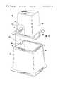
- FIG. 1is an exploded three-dimensional view with parts broken away of a pedestal structure according to this invention with the cover separated above the base;
- FIG. 2is an exploded three-dimensional view with parts broken away of the two cooperating portions of the securing mechanism used in the pedestal of FIG. 1;
- FIG. 3is a side sectional view of a portion of the base and cover with portions broken away to show the secure engagement of the cover with the base and the tight engagement of the tongue and groove when the securing mechanism has been operated;
- FIG. 4is a front elevational view showing just the housing portion of the securing mechanism with a guard lock in place.
- FIG. 1a pedestal structure 10 according to this invention including a cover 12 and base 14 .
- Cover 12includes an overhanging lip 16 which accommodates upstanding baffle 18 on base 14 to prevent the insertion of objects from the outside in or from the inside out which could convey hazardous electrical energy.
- On one side 20 of cover 12there is a tongue 22 formed of a vertical section 24 and a horizontal section 26 which is sized to pass through groove 28 on side 29 of base 14 when cover 12 is in position engaged with base 14 .
- a securing mechanism 30includes a securing portion 32 on cover 12 and a second securing portion 34 on base 14 . Secured portions 32 and 34 are on corresponding sides 36 and 38 of cover 12 and base 14 across from opposing sides 20 and 29 .
- the securing mechanism and the tongue and groove arrangementshould be on opposing sides of the structure. They don't have to be exactly diametrically opposed, but whether the structure is circular, polygonal, square or rectangular as shown, or any other form, they should be in opposing relationship so that some component of the force applied by securing mechanism 30 is applied to tightly engage tongue 32 with groove 28 .
- Securing mechanism 30is shown in greater detail in FIG. 2 .
- Securing portion 32includes a mounting plate 40 which is mounted to side 36 of cover 12 by means of epoxy adhesive or bolts, not shown, through holes 42 and 44 .
- a clearance hole 46is provided to receive the threaded shaft 48 of bolt 50 which has a pentagonal shaped head 52 conforming to pentagonal wrenches used in the electrical power industry.
- Bolt 50is surrounded by cylindrical housing 54 which is typically welded to plate 40 although in FIG. 2 it is shown exploded away from it for purposes of illustration.
- housing 54Inside of housing 54 is a biasing device, spring 56 , which seats on plate 40 and exerts a force on the head 52 of bolt 50 through retaining washer 58 which is retained by means of detents 60 which, for example, may be simply spot welds that overlap the wall of cylindrical housing 54 .
- a hole 62is provided to receive the hasp of a lock so that when bolt 50 is tightened and head 52 is driven into cylindrical housing 54 , the hasp will block the front face of head 52 so that it cannot be easily removed. This is shown in more detail in FIGS. 3 and 4.
- Portion 32 of securing mechanism 40includes a nut 70 , FIGS. 2 and 3, having an internally threaded bore 72 with a beveled entrance 74 , FIG. 2, to assist in centering bolt 50 .
- slots 75 , 76is provided wherein nut 70 can move up and down and slightly sideways.
- a non-conductive retaining dowel, e.g., nylon dowel 80is force-fitted in the top of slots 75 and 76 to keep nut 70 in the slot.
- a shieldis formed by well 82 to at least partially shield mechanically and electrically nut 70 and bolt 50 when they are engaged and bolt extends through nut 70 into well 82 .
- cover 12In operation, cover 12 , FIG. 3, is brought straight down without tilting onto base 14 .
- the threaded portion 48 of bolt 50is centered in threaded hole 72 of nut 70 which is free to float to a limited degree in slots 75 and 76 .
- spring 56exerts a force against plate 40 which drives the cover to the right as shown by arrows 90 , 92 .
- hole 62is clear for acceptance of the hasp 100 , FIG. 4, of lock 102 fs that the hasp blocks the face or the head 52 of bolt 50 so that it cannot be easily accessed by a wrench or other means to loosen it.
Landscapes
- Engineering & Computer Science (AREA)
- Power Engineering (AREA)
- Casings For Electric Apparatus (AREA)
Abstract
Description
Claims (15)
Priority Applications (1)
| Application Number | Priority Date | Filing Date | Title |
|---|---|---|---|
| US09/323,716US6362419B1 (en) | 1999-06-01 | 1999-06-01 | Pedestal structure for housing electrical power connections and other equipment |
Applications Claiming Priority (1)
| Application Number | Priority Date | Filing Date | Title |
|---|---|---|---|
| US09/323,716US6362419B1 (en) | 1999-06-01 | 1999-06-01 | Pedestal structure for housing electrical power connections and other equipment |
Publications (1)
| Publication Number | Publication Date |
|---|---|
| US6362419B1true US6362419B1 (en) | 2002-03-26 |
Family
ID=23260406
Family Applications (1)
| Application Number | Title | Priority Date | Filing Date |
|---|---|---|---|
| US09/323,716Expired - LifetimeUS6362419B1 (en) | 1999-06-01 | 1999-06-01 | Pedestal structure for housing electrical power connections and other equipment |
Country Status (1)
| Country | Link |
|---|---|
| US (1) | US6362419B1 (en) |
Cited By (27)
| Publication number | Priority date | Publication date | Assignee | Title |
|---|---|---|---|---|
| US6518499B1 (en)* | 2001-08-10 | 2003-02-11 | Utility Marketing Corporation | Box pad for mounting electrical equipment |
| US20050103782A1 (en)* | 2003-11-17 | 2005-05-19 | Rain Bird Corporation | Interlocking valve box and lid |
| US20050215090A1 (en)* | 2004-03-12 | 2005-09-29 | Charles Industries, Ltd. | Electronic enclosure |
| US20050247851A1 (en)* | 2004-05-05 | 2005-11-10 | Kessler Seth S | Molded pad for mounting electrical equipment |
| US20050275319A1 (en)* | 2004-06-10 | 2005-12-15 | Charles Industries, Ltd. | Enclosure for telecommunications equipment |
| US20060090917A1 (en)* | 2004-11-02 | 2006-05-04 | Lowe George T | Support base with movable mounting pad |
| US20060201213A1 (en)* | 2005-03-09 | 2006-09-14 | Burke Edward J | Locking system for grade level enclosures |
| US20070284370A1 (en)* | 2006-06-08 | 2007-12-13 | Eaton Corporation | Outdoor electrical enclosure and hinge-less door assembly therefor |
| USD562588S1 (en)* | 2005-03-17 | 2008-02-26 | Standard Display Systems, Llc | Display base |
| US7351909B1 (en) | 2004-06-10 | 2008-04-01 | Charles Industries, Ltd. | Multilayered housing for electronics enclosures |
| US20080087671A1 (en)* | 2006-10-14 | 2008-04-17 | Stephen Lynn Kreider | Device for containment and protection of a liquid handling system |
| US20090032115A1 (en)* | 2004-01-22 | 2009-02-05 | Tadahiro Ohmi | Vacuum thermal insulating valve |
| US20090145917A1 (en)* | 2007-12-11 | 2009-06-11 | Jason Wojcik | Tamper-Proof Irrigation Box |
| US20090173397A1 (en)* | 2008-01-04 | 2009-07-09 | Rain Bird Corporation | Equipment Housing with Access Knockouts |
| US20090260925A1 (en)* | 2008-04-16 | 2009-10-22 | Schilling Robert J | Underground enclosure system for storing components, cables, and the like |
| GB2465403A (en)* | 2008-11-18 | 2010-05-19 | Festive Lights Ltd | Container suitable for protecting electrical connector |
| US20120091130A1 (en)* | 2010-10-06 | 2012-04-19 | Touchet Chad B | Expandable Backflow Cage |
| US8220298B2 (en) | 2009-02-17 | 2012-07-17 | Channell Commercial Corporation | Self-latching locking assembly |
| US20140196380A1 (en)* | 2013-01-15 | 2014-07-17 | Channell Commercial Corp. | Grade level enclosure conversion assembly |
| US20160002895A1 (en)* | 2014-07-04 | 2016-01-07 | Babs B. Touchet | Adjustable backflow enclosure |
| USD780703S1 (en)* | 2014-10-20 | 2017-03-07 | S.J. Electro Systems, Inc. | Control panel cover |
| US9768592B2 (en) | 2015-08-19 | 2017-09-19 | Hubbell Incorporated | Utility enclosure pedestal |
| US10167616B2 (en) | 2017-02-17 | 2019-01-01 | Mueller International, Llc | Method of coupling a pit extension to a pit liner of a pit vault |
| US20210185840A1 (en)* | 2019-12-17 | 2021-06-17 | Ppc Broadband, Inc. | Node pedestal |
| USD1054453S1 (en)* | 2020-11-13 | 2024-12-17 | Jerry L. McKinney | Pedestal |
| US20250273945A1 (en)* | 2024-02-27 | 2025-08-28 | Channell Commercial Corporation | Enclosure system for underground utility connections |
| USD1093136S1 (en)* | 2024-06-18 | 2025-09-16 | Christopher Corbett | Pedestal screw insert |
Citations (3)
| Publication number | Priority date | Publication date | Assignee | Title |
|---|---|---|---|---|
| US3868040A (en)* | 1973-10-30 | 1975-02-25 | Jr Holger C Langmack | Equipment covering |
| US4158102A (en)* | 1978-03-27 | 1979-06-12 | Bright William L | Enclosure for equipment |
| US4365108A (en)* | 1981-07-09 | 1982-12-21 | Bright William L | Secondary power pedestal for electrical equipment |
- 1999
- 1999-06-01USUS09/323,716patent/US6362419B1/ennot_activeExpired - Lifetime
Patent Citations (3)
| Publication number | Priority date | Publication date | Assignee | Title |
|---|---|---|---|---|
| US3868040A (en)* | 1973-10-30 | 1975-02-25 | Jr Holger C Langmack | Equipment covering |
| US4158102A (en)* | 1978-03-27 | 1979-06-12 | Bright William L | Enclosure for equipment |
| US4365108A (en)* | 1981-07-09 | 1982-12-21 | Bright William L | Secondary power pedestal for electrical equipment |
Cited By (47)
| Publication number | Priority date | Publication date | Assignee | Title |
|---|---|---|---|---|
| US6518499B1 (en)* | 2001-08-10 | 2003-02-11 | Utility Marketing Corporation | Box pad for mounting electrical equipment |
| US20050103782A1 (en)* | 2003-11-17 | 2005-05-19 | Rain Bird Corporation | Interlocking valve box and lid |
| WO2005050070A3 (en)* | 2003-11-17 | 2006-04-13 | Rain Bird Corp | Interlocking valve box and lid |
| US7243810B2 (en) | 2003-11-17 | 2007-07-17 | Rain Bird Corporation | Interlocking valve box and lid |
| US20090032115A1 (en)* | 2004-01-22 | 2009-02-05 | Tadahiro Ohmi | Vacuum thermal insulating valve |
| US7673649B2 (en)* | 2004-01-22 | 2010-03-09 | Fujikin Incorporated | Vacuum thermal insulating valve |
| US20050215090A1 (en)* | 2004-03-12 | 2005-09-29 | Charles Industries, Ltd. | Electronic enclosure |
| US7193151B2 (en)* | 2004-03-12 | 2007-03-20 | Charles Industries, Ltd. | Electronic enclosure |
| US20050247851A1 (en)* | 2004-05-05 | 2005-11-10 | Kessler Seth S | Molded pad for mounting electrical equipment |
| US7351909B1 (en) | 2004-06-10 | 2008-04-01 | Charles Industries, Ltd. | Multilayered housing for electronics enclosures |
| US20050275319A1 (en)* | 2004-06-10 | 2005-12-15 | Charles Industries, Ltd. | Enclosure for telecommunications equipment |
| US20060090917A1 (en)* | 2004-11-02 | 2006-05-04 | Lowe George T | Support base with movable mounting pad |
| US7385137B2 (en)* | 2005-03-09 | 2008-06-10 | Channell Commercial Corporation | Enclosure system for underground utility connections |
| US7381888B2 (en) | 2005-03-09 | 2008-06-03 | Channell Commercial Corporation | Grade level enclosures for underground utility connections |
| US20060254794A1 (en)* | 2005-03-09 | 2006-11-16 | Burke Edward J | Enclosure system for underground utility connections |
| US20060231279A1 (en)* | 2005-03-09 | 2006-10-19 | Burke Edward J | Grade level enclosures for underground utility connections |
| US7547051B2 (en) | 2005-03-09 | 2009-06-16 | Channell Commercial Corporation | Locking system for grade level enclosures |
| US20060201213A1 (en)* | 2005-03-09 | 2006-09-14 | Burke Edward J | Locking system for grade level enclosures |
| USD562588S1 (en)* | 2005-03-17 | 2008-02-26 | Standard Display Systems, Llc | Display base |
| US20070284370A1 (en)* | 2006-06-08 | 2007-12-13 | Eaton Corporation | Outdoor electrical enclosure and hinge-less door assembly therefor |
| US7361832B2 (en)* | 2006-06-08 | 2008-04-22 | Dively Robert C | Outdoor electrical enclosure and hinge-less door assembly therefor |
| US20080087671A1 (en)* | 2006-10-14 | 2008-04-17 | Stephen Lynn Kreider | Device for containment and protection of a liquid handling system |
| US7971742B2 (en)* | 2006-10-14 | 2011-07-05 | Stephen Lynn Kreider | Device for containment, protection and easy installation and removal of a liquid handling system |
| US20090145917A1 (en)* | 2007-12-11 | 2009-06-11 | Jason Wojcik | Tamper-Proof Irrigation Box |
| US20090173397A1 (en)* | 2008-01-04 | 2009-07-09 | Rain Bird Corporation | Equipment Housing with Access Knockouts |
| US8813916B2 (en)* | 2008-04-16 | 2014-08-26 | Clear View Enclosures, Inc. | Underground enclosure system for storing components, cables, and the like |
| US20140346932A1 (en)* | 2008-04-16 | 2014-11-27 | Clear View Enclosures, Inc. | Underground enclosure system for storing components, cables, and the like |
| US20090260925A1 (en)* | 2008-04-16 | 2009-10-22 | Schilling Robert J | Underground enclosure system for storing components, cables, and the like |
| GB2465403B (en)* | 2008-11-18 | 2013-02-13 | Mark Christopher Higginson | Container arrangement |
| GB2465403A (en)* | 2008-11-18 | 2010-05-19 | Festive Lights Ltd | Container suitable for protecting electrical connector |
| US8881923B2 (en) | 2008-11-18 | 2014-11-11 | Mark Christopher Higginson | Sealable container having a lid |
| WO2010058192A1 (en) | 2008-11-18 | 2010-05-27 | Festive Lights Limited | Container arrangement |
| US8220298B2 (en) | 2009-02-17 | 2012-07-17 | Channell Commercial Corporation | Self-latching locking assembly |
| US20120091130A1 (en)* | 2010-10-06 | 2012-04-19 | Touchet Chad B | Expandable Backflow Cage |
| US20140196380A1 (en)* | 2013-01-15 | 2014-07-17 | Channell Commercial Corp. | Grade level enclosure conversion assembly |
| US8847070B2 (en)* | 2013-01-15 | 2014-09-30 | Channell Commercial Corporation | Grade level enclosure conversion assembly |
| US20160002895A1 (en)* | 2014-07-04 | 2016-01-07 | Babs B. Touchet | Adjustable backflow enclosure |
| USD780703S1 (en)* | 2014-10-20 | 2017-03-07 | S.J. Electro Systems, Inc. | Control panel cover |
| USD803168S1 (en) | 2014-10-20 | 2017-11-21 | S. J. Electro Systems, Inc. | Control panel cover |
| US9768592B2 (en) | 2015-08-19 | 2017-09-19 | Hubbell Incorporated | Utility enclosure pedestal |
| US10167616B2 (en) | 2017-02-17 | 2019-01-01 | Mueller International, Llc | Method of coupling a pit extension to a pit liner of a pit vault |
| US10174486B2 (en)* | 2017-02-17 | 2019-01-08 | Mueller International, Llc | Pit extension |
| US20210185840A1 (en)* | 2019-12-17 | 2021-06-17 | Ppc Broadband, Inc. | Node pedestal |
| US12057682B2 (en)* | 2019-12-17 | 2024-08-06 | Ppc Broadband, Inc. | Node pedestal |
| USD1054453S1 (en)* | 2020-11-13 | 2024-12-17 | Jerry L. McKinney | Pedestal |
| US20250273945A1 (en)* | 2024-02-27 | 2025-08-28 | Channell Commercial Corporation | Enclosure system for underground utility connections |
| USD1093136S1 (en)* | 2024-06-18 | 2025-09-16 | Christopher Corbett | Pedestal screw insert |
Similar Documents
| Publication | Publication Date | Title |
|---|---|---|
| US6362419B1 (en) | Pedestal structure for housing electrical power connections and other equipment | |
| EP1459412B2 (en) | Locking connector | |
| KR20210116249A (en) | lockout tagout assembly and system and method of using same | |
| US4579410A (en) | Security attachment for electrical plug | |
| US3867822A (en) | Locking means for electric meters | |
| GB2433547A (en) | Clamping mechanism for securing a surveillance camera housing to a ceiling structure | |
| US4494809A (en) | Security attachment for electrical plug | |
| US4603931A (en) | Anti-theft device for appliances with electrical AC power cords | |
| US7800884B2 (en) | Protective device against electrical discharges in fixing elements | |
| US5620291A (en) | Quick disconnect fastener | |
| US3569908A (en) | Connector assembly | |
| US5449867A (en) | Circuit breaker operating handle interlock | |
| JP2015023034A (en) | Quick connect power connector | |
| WO1996032760A1 (en) | Electrical connector with secondary lock | |
| US9698532B2 (en) | Safety electrical lockout arrangement | |
| US10784624B2 (en) | Protective separator for a right angle plug connection | |
| US4872847A (en) | Pilfer proofing system for electric utility meter box | |
| US4820187A (en) | Tamper-proof electrical receptacle | |
| US6528913B1 (en) | Electric device grounding system | |
| US20080277249A1 (en) | Circuit breaker with improved lock-off accessory | |
| US4284300A (en) | Security locking assembly | |
| KR940004889A (en) | Bolted electrical connector | |
| US4382155A (en) | Lock for a test station apparatus | |
| JP2003317823A (en) | Terminal protection cap | |
| US3440590A (en) | Fastener device |
Legal Events
| Date | Code | Title | Description |
|---|---|---|---|
| AS | Assignment | Owner name:HIGHLINE PRODUCTS, INC., MASSACHUSETTS Free format text:ASSIGNMENT OF ASSIGNORS INTEREST;ASSIGNORS:GALLAGHER, BONNIE C.;CHERRY, STEVEN G.;MCMURRAY, CHARLES EDWARD;REEL/FRAME:010058/0986;SIGNING DATES FROM 19990513 TO 19990518 | |
| AS | Assignment | Owner name:UTILITY MARKETING CORPORATION D/B/A HIGHLINE PRODU Free format text:CORRECTIVE ASSIGNMENT TO CORRECT THE ASSIGNEE, PREVIOUSLY RECORDED ON REEL 010058 FRAME 0986;ASSIGNORS:CHERRY, STEVEN G.;MCMURRAY, CHARLES EDWARD;GALLAGHER, BONNIE C.;REEL/FRAME:012412/0038;SIGNING DATES FROM 20010924 TO 20011009 | |
| STCF | Information on status: patent grant | Free format text:PATENTED CASE | |
| AS | Assignment | Owner name:CITIZENS BANK OF MASSACHUSETTS, MASSACHUSETTS Free format text:SECURITY INTEREST;ASSIGNOR:UTILITY MARKETING CORPORATION;REEL/FRAME:014709/0187 Effective date:20031114 | |
| FEPP | Fee payment procedure | Free format text:PAYOR NUMBER ASSIGNED (ORIGINAL EVENT CODE: ASPN); ENTITY STATUS OF PATENT OWNER: SMALL ENTITY | |
| FPAY | Fee payment | Year of fee payment:4 | |
| FEPP | Fee payment procedure | Free format text:PAYER NUMBER DE-ASSIGNED (ORIGINAL EVENT CODE: RMPN); ENTITY STATUS OF PATENT OWNER: SMALL ENTITY Free format text:PAYOR NUMBER ASSIGNED (ORIGINAL EVENT CODE: ASPN); ENTITY STATUS OF PATENT OWNER: SMALL ENTITY | |
| FPAY | Fee payment | Year of fee payment:8 | |
| AS | Assignment | Owner name:UTILITY MARKETING CORPORATION, MASSACHUSETTS Free format text:RELEASE BY SECURED PARTY;ASSIGNOR:CITIZENS BANK OF MASSACHUSETTS;REEL/FRAME:030374/0014 Effective date:20130505 | |
| FPAY | Fee payment | Year of fee payment:12 | |
| AS | Assignment | Owner name:MACLEAN HIGHLINE, L.L.C., SOUTH CAROLINA Free format text:ASSIGNMENT OF ASSIGNORS INTEREST;ASSIGNORS:UTILITY MARKETING CORPORATION;U.S. UTILITY ENCLOSURES, LLC;REEL/FRAME:033478/0721 Effective date:20130603 | |
| AS | Assignment | Owner name:MACLEAN POWER, L.L.C., SOUTH CAROLINA Free format text:MERGER;ASSIGNOR:MACLEAN HIGHLINE, L.L.C.;REEL/FRAME:033569/0939 Effective date:20140130 | |
| AS | Assignment | Owner name:ARES CAPITAL CORPORATION, AS COLLATERAL AGENT, VIRGINIA Free format text:SECURITY INTEREST;ASSIGNOR:MACLEAN POWER, L.L.C.;REEL/FRAME:047844/0516 Effective date:20181221 Owner name:ARES CAPITAL CORPORATION, AS COLLATERAL AGENT, VIR Free format text:SECURITY INTEREST;ASSIGNOR:MACLEAN POWER, L.L.C.;REEL/FRAME:047844/0516 Effective date:20181221 | |
| AS | Assignment | Owner name:BANK OF AMERICA, N.A., AS ABL COLLATERAL AGENT, WISCONSIN Free format text:SECURITY INTEREST;ASSIGNOR:MACLEAN POWER, L.L.C.;REEL/FRAME:047848/0319 Effective date:20181221 Owner name:BANK OF AMERICA, N.A., AS ABL COLLATERAL AGENT, WI Free format text:SECURITY INTEREST;ASSIGNOR:MACLEAN POWER, L.L.C.;REEL/FRAME:047848/0319 Effective date:20181221 | |
| AS | Assignment | Owner name:MACLEAN POWER, L.L.C., ILLINOIS Free format text:PATENT ASSIGNMENT;ASSIGNORS:UTILITY MARKETING CORPORATION;U.S. UTILITY ENCLOSURES, LLC;REEL/FRAME:051324/0248 Effective date:20130603 | |
| AS | Assignment | Owner name:MACLEAN SENIOR INDUSTRIES, L.L.C., ILLINOIS Free format text:RELEASE OF SECURITY INTEREST IN INTELLECTUAL PROPERTY COLLATERAL;ASSIGNOR:ARES CAPITAL CORPORATION;REEL/FRAME:061658/0161 Effective date:20221011 Owner name:MACLEAN POWER, L.L.C., ILLINOIS Free format text:RELEASE OF SECURITY INTEREST IN INTELLECTUAL PROPERTY COLLATERAL;ASSIGNOR:ARES CAPITAL CORPORATION;REEL/FRAME:061658/0161 Effective date:20221011 Owner name:MAC LEAN-FOGG COMPANY, ILLINOIS Free format text:RELEASE OF SECURITY INTEREST IN INTELLECTUAL PROPERTY COLLATERAL;ASSIGNOR:ARES CAPITAL CORPORATION;REEL/FRAME:061658/0161 Effective date:20221011 Owner name:MACLEAN SENIOR INDUSTRIES, L.L.C., ILLINOIS Free format text:PARTIAL RELEASE OF SECURITY INTEREST IN INTELLECTUAL PROPERTY COLLATERAL;ASSIGNOR:BANK OF AMERICA, N.A., AS ABL COLLATERAL AGENT;REEL/FRAME:061661/0798 Effective date:20221011 Owner name:MACLEAN POWER, L.L.C., ILLINOIS Free format text:PARTIAL RELEASE OF SECURITY INTEREST IN INTELLECTUAL PROPERTY COLLATERAL;ASSIGNOR:BANK OF AMERICA, N.A., AS ABL COLLATERAL AGENT;REEL/FRAME:061661/0798 Effective date:20221011 Owner name:MAC LEAN-FOGG COMPANY, ILLINOIS Free format text:PARTIAL RELEASE OF SECURITY INTEREST IN INTELLECTUAL PROPERTY COLLATERAL;ASSIGNOR:BANK OF AMERICA, N.A., AS ABL COLLATERAL AGENT;REEL/FRAME:061661/0798 Effective date:20221011 |