US6361559B1 - Thermal securing anastomosis systems - Google Patents
Thermal securing anastomosis systemsDownload PDFInfo
- Publication number
- US6361559B1 US6361559B1US09/329,504US32950499AUS6361559B1US 6361559 B1US6361559 B1US 6361559B1US 32950499 AUS32950499 AUS 32950499AUS 6361559 B1US6361559 B1US 6361559B1
- Authority
- US
- United States
- Prior art keywords
- fitting
- bypass graft
- vessel
- electrode
- bypass
- Prior art date
- Legal status (The legal status is an assumption and is not a legal conclusion. Google has not performed a legal analysis and makes no representation as to the accuracy of the status listed.)
- Expired - Fee Related
Links
- 230000003872anastomosisEffects0.000titleabstractdescription80
- 230000006835compressionEffects0.000claimsabstractdescription31
- 238000007906compressionMethods0.000claimsabstractdescription31
- 230000007246mechanismEffects0.000claimsabstractdescription25
- 238000003780insertionMethods0.000claimsdescription25
- 230000037431insertionEffects0.000claimsdescription25
- 230000003014reinforcing effectEffects0.000claimsdescription3
- 210000000746body regionAnatomy0.000claims1
- 230000005284excitationEffects0.000claims1
- 239000000463materialSubstances0.000description59
- 230000017531blood circulationEffects0.000description38
- 238000000034methodMethods0.000description32
- 210000001519tissueAnatomy0.000description22
- 239000012530fluidSubstances0.000description18
- BASFCYQUMIYNBI-UHFFFAOYSA-NplatinumChemical compound[Pt]BASFCYQUMIYNBI-UHFFFAOYSA-N0.000description14
- 239000008280bloodSubstances0.000description13
- 210000004369bloodAnatomy0.000description13
- 230000000284resting effectEffects0.000description11
- 210000004351coronary vesselAnatomy0.000description10
- 230000008569processEffects0.000description10
- 210000001367arteryAnatomy0.000description9
- 229920000642polymerPolymers0.000description9
- 208000007536ThrombosisDiseases0.000description8
- 208000027418Wounds and injuryDiseases0.000description8
- HZEWFHLRYVTOIW-UHFFFAOYSA-N[Ti].[Ni]Chemical compound[Ti].[Ni]HZEWFHLRYVTOIW-UHFFFAOYSA-N0.000description8
- 238000004519manufacturing processMethods0.000description8
- 229910001000nickel titaniumInorganic materials0.000description8
- 238000013459approachMethods0.000description7
- 239000004020conductorSubstances0.000description7
- 238000013461designMethods0.000description7
- 238000002347injectionMethods0.000description7
- 239000007924injectionSubstances0.000description7
- 238000001746injection mouldingMethods0.000description7
- 230000013011matingEffects0.000description7
- 229910052697platinumInorganic materials0.000description7
- 239000011148porous materialSubstances0.000description7
- 229910001220stainless steelInorganic materials0.000description7
- 239000010935stainless steelSubstances0.000description7
- 102000008186CollagenHuman genes0.000description6
- 108010035532CollagenProteins0.000description6
- 230000002612cardiopulmonary effectEffects0.000description6
- 229920001436collagenPolymers0.000description6
- 239000002131composite materialSubstances0.000description6
- 230000006870functionEffects0.000description6
- 238000010438heat treatmentMethods0.000description6
- 210000003462veinAnatomy0.000description6
- RTAQQCXQSZGOHL-UHFFFAOYSA-NTitaniumChemical compound[Ti]RTAQQCXQSZGOHL-UHFFFAOYSA-N0.000description5
- 239000000853adhesiveSubstances0.000description5
- 230000001070adhesive effectEffects0.000description5
- 210000000709aortaAnatomy0.000description5
- 238000007598dipping methodMethods0.000description5
- 229920001971elastomerPolymers0.000description5
- 239000000806elastomerSubstances0.000description5
- 230000003511endothelial effectEffects0.000description5
- 230000003902lesionEffects0.000description5
- 230000004048modificationEffects0.000description5
- 238000012986modificationMethods0.000description5
- 230000004044responseEffects0.000description5
- 229920001187thermosetting polymerPolymers0.000description5
- 229910052719titaniumInorganic materials0.000description5
- 239000010936titaniumSubstances0.000description5
- 238000003466weldingMethods0.000description5
- 229910045601alloyInorganic materials0.000description4
- 239000000956alloySubstances0.000description4
- 210000003484anatomyAnatomy0.000description4
- 230000008901benefitEffects0.000description4
- 210000004204blood vesselAnatomy0.000description4
- 230000002439hemostatic effectEffects0.000description4
- 238000003384imaging methodMethods0.000description4
- 229910052751metalInorganic materials0.000description4
- 239000002184metalSubstances0.000description4
- 229920001296polysiloxanePolymers0.000description4
- 238000005476solderingMethods0.000description4
- 229920001169thermoplasticPolymers0.000description4
- 239000004416thermosoftening plasticSubstances0.000description4
- 206010002329AneurysmDiseases0.000description3
- 239000004593EpoxySubstances0.000description3
- JOYRKODLDBILNP-UHFFFAOYSA-NEthyl urethaneChemical compoundCCOC(N)=OJOYRKODLDBILNP-UHFFFAOYSA-N0.000description3
- 239000004698PolyethyleneSubstances0.000description3
- 230000015572biosynthetic processEffects0.000description3
- 230000001112coagulating effectEffects0.000description3
- 239000011248coating agentSubstances0.000description3
- 238000000576coating methodMethods0.000description3
- 230000008602contractionEffects0.000description3
- 239000013013elastic materialSubstances0.000description3
- PCHJSUWPFVWCPO-UHFFFAOYSA-NgoldChemical compound[Au]PCHJSUWPFVWCPO-UHFFFAOYSA-N0.000description3
- 229910052737goldInorganic materials0.000description3
- 239000010931goldSubstances0.000description3
- 230000023597hemostasisEffects0.000description3
- 238000007735ion beam assisted depositionMethods0.000description3
- 230000033001locomotionEffects0.000description3
- 210000001349mammary arteryAnatomy0.000description3
- 238000007649pad printingMethods0.000description3
- 238000010422paintingMethods0.000description3
- 230000002093peripheral effectEffects0.000description3
- HWLDNSXPUQTBOD-UHFFFAOYSA-Nplatinum-iridium alloyChemical compound[Ir].[Pt]HWLDNSXPUQTBOD-UHFFFAOYSA-N0.000description3
- -1polyethylenePolymers0.000description3
- 229920000573polyethylenePolymers0.000description3
- 210000002321radial arteryAnatomy0.000description3
- 210000003752saphenous veinAnatomy0.000description3
- 238000004544sputter depositionMethods0.000description3
- 229910052715tantalumInorganic materials0.000description3
- GUVRBAGPIYLISA-UHFFFAOYSA-Ntantalum atomChemical compound[Ta]GUVRBAGPIYLISA-UHFFFAOYSA-N0.000description3
- WFKWXMTUELFFGS-UHFFFAOYSA-NtungstenChemical compound[W]WFKWXMTUELFFGS-UHFFFAOYSA-N0.000description3
- 229910052721tungstenInorganic materials0.000description3
- 239000010937tungstenSubstances0.000description3
- 206010016717FistulaDiseases0.000description2
- HTTJABKRGRZYRN-UHFFFAOYSA-NHeparinChemical compoundOC1C(NC(=O)C)C(O)OC(COS(O)(=O)=O)C1OC1C(OS(O)(=O)=O)C(O)C(OC2C(C(OS(O)(=O)=O)C(OC3C(C(O)C(O)C(O3)C(O)=O)OS(O)(=O)=O)C(CO)O2)NS(O)(=O)=O)C(C(O)=O)O1HTTJABKRGRZYRN-UHFFFAOYSA-N0.000description2
- 239000004677NylonSubstances0.000description2
- 208000031481Pathologic ConstrictionDiseases0.000description2
- BQCADISMDOOEFD-UHFFFAOYSA-NSilverChemical compound[Ag]BQCADISMDOOEFD-UHFFFAOYSA-N0.000description2
- 206010053648Vascular occlusionDiseases0.000description2
- 208000002223abdominal aortic aneurysmDiseases0.000description2
- 230000003190augmentative effectEffects0.000description2
- 238000010009beatingMethods0.000description2
- 238000009954braidingMethods0.000description2
- 230000015556catabolic processEffects0.000description2
- 238000006243chemical reactionMethods0.000description2
- 238000010276constructionMethods0.000description2
- 208000029078coronary artery diseaseDiseases0.000description2
- 238000005553drillingMethods0.000description2
- 229940079593drugDrugs0.000description2
- 239000003814drugSubstances0.000description2
- 230000001747exhibiting effectEffects0.000description2
- 230000003890fistulaEffects0.000description2
- 238000002594fluoroscopyMethods0.000description2
- 230000004927fusionEffects0.000description2
- 238000001631haemodialysisMethods0.000description2
- 230000000322hemodialysisEffects0.000description2
- 229960002897heparinDrugs0.000description2
- 229920000669heparinPolymers0.000description2
- 208000028867ischemiaDiseases0.000description2
- 239000007769metal materialSubstances0.000description2
- 229920001778nylonPolymers0.000description2
- 210000000056organAnatomy0.000description2
- 210000003101oviductAnatomy0.000description2
- 239000004810polytetrafluoroethyleneSubstances0.000description2
- 229920001343polytetrafluoroethylenePolymers0.000description2
- 210000002254renal arteryAnatomy0.000description2
- 238000012216screeningMethods0.000description2
- 238000000926separation methodMethods0.000description2
- 229910052709silverInorganic materials0.000description2
- 239000004332silverSubstances0.000description2
- 239000000243solutionSubstances0.000description2
- 239000000758substrateSubstances0.000description2
- 230000008093supporting effectEffects0.000description2
- 238000001356surgical procedureMethods0.000description2
- 229920002994synthetic fiberPolymers0.000description2
- 230000007704transitionEffects0.000description2
- 238000011282treatmentMethods0.000description2
- 210000000689upper legAnatomy0.000description2
- 230000002792vascularEffects0.000description2
- 230000006496vascular abnormalityEffects0.000description2
- 208000019553vascular diseaseDiseases0.000description2
- 238000012800visualizationMethods0.000description2
- 206010003210ArteriosclerosisDiseases0.000description1
- 201000001320AtherosclerosisDiseases0.000description1
- 241000282465CanisSpecies0.000description1
- 208000001778Coronary OcclusionDiseases0.000description1
- 206010011086Coronary artery occlusionDiseases0.000description1
- 208000033978Device electrical impedance issueDiseases0.000description1
- 102000008946FibrinogenHuman genes0.000description1
- 108010049003FibrinogenProteins0.000description1
- 108010010803GelatinProteins0.000description1
- 208000010496Heart ArrestDiseases0.000description1
- 206010061216InfarctionDiseases0.000description1
- 241001465754MetazoaSpecies0.000description1
- 239000004696Poly ether ether ketoneSubstances0.000description1
- 239000004952PolyamideSubstances0.000description1
- 208000025865UlcerDiseases0.000description1
- 238000005299abrasionMethods0.000description1
- 230000006978adaptationEffects0.000description1
- 238000004873anchoringMethods0.000description1
- 238000002399angioplastyMethods0.000description1
- 239000003146anticoagulant agentSubstances0.000description1
- 208000007474aortic aneurysmDiseases0.000description1
- 208000011775arteriosclerosis diseaseDiseases0.000description1
- 230000009286beneficial effectEffects0.000description1
- JUPQTSLXMOCDHR-UHFFFAOYSA-Nbenzene-1,4-diol;bis(4-fluorophenyl)methanoneChemical compoundOC1=CC=C(O)C=C1.C1=CC(F)=CC=C1C(=O)C1=CC=C(F)C=C1JUPQTSLXMOCDHR-UHFFFAOYSA-N0.000description1
- 230000005540biological transmissionEffects0.000description1
- 230000000740bleeding effectEffects0.000description1
- 230000036772blood pressureEffects0.000description1
- 230000000747cardiac effectEffects0.000description1
- 210000002434celiac arteryAnatomy0.000description1
- 230000010261cell growthEffects0.000description1
- 230000008859changeEffects0.000description1
- 238000003486chemical etchingMethods0.000description1
- 210000000038chestAnatomy0.000description1
- 230000015271coagulationEffects0.000description1
- 238000005345coagulationMethods0.000description1
- 239000002872contrast mediaSubstances0.000description1
- 238000007796conventional methodMethods0.000description1
- 238000002788crimpingMethods0.000description1
- 239000013078crystalSubstances0.000description1
- 230000006378damageEffects0.000description1
- 230000007547defectEffects0.000description1
- 230000000916dilatatory effectEffects0.000description1
- 238000009826distributionMethods0.000description1
- 230000009977dual effectEffects0.000description1
- 238000009760electrical discharge machiningMethods0.000description1
- 238000005516engineering processMethods0.000description1
- 210000005081epithelial layerAnatomy0.000description1
- 238000002474experimental methodMethods0.000description1
- 238000001125extrusionMethods0.000description1
- 210000001105femoral arteryAnatomy0.000description1
- 210000003191femoral veinAnatomy0.000description1
- 239000000835fiberSubstances0.000description1
- 229940012952fibrinogenDrugs0.000description1
- 230000002496gastric effectEffects0.000description1
- 229920000159gelatinPolymers0.000description1
- 239000008273gelatinSubstances0.000description1
- 235000019322gelatineNutrition0.000description1
- 235000011852gelatine dessertsNutrition0.000description1
- 238000003306harvestingMethods0.000description1
- 238000002513implantationMethods0.000description1
- 239000011261inert gasSubstances0.000description1
- 230000007574infarctionEffects0.000description1
- 208000000509infertilityDiseases0.000description1
- 230000036512infertilityEffects0.000description1
- 231100000535infertilityToxicity0.000description1
- 230000003993interactionEffects0.000description1
- 230000003601intercostal effectEffects0.000description1
- 210000003734kidneyAnatomy0.000description1
- 210000002414legAnatomy0.000description1
- 230000007774longtermEffects0.000description1
- 210000004072lungAnatomy0.000description1
- 229910000734martensiteInorganic materials0.000description1
- 238000005259measurementMethods0.000description1
- 229940127554medical productDrugs0.000description1
- 238000002844meltingMethods0.000description1
- 230000008018meltingEffects0.000description1
- 210000003975mesenteric arteryAnatomy0.000description1
- 150000002739metalsChemical class0.000description1
- 238000002406microsurgeryMethods0.000description1
- 238000003801millingMethods0.000description1
- 230000000116mitigating effectEffects0.000description1
- 230000035515penetrationEffects0.000description1
- 230000010412perfusionEffects0.000description1
- 229920002647polyamidePolymers0.000description1
- 239000004417polycarbonateSubstances0.000description1
- 229920000515polycarbonatePolymers0.000description1
- 229920000728polyesterPolymers0.000description1
- 229920002530polyetherether ketonePolymers0.000description1
- 238000003825pressingMethods0.000description1
- 239000000047productSubstances0.000description1
- 230000002035prolonged effectEffects0.000description1
- 238000005086pumpingMethods0.000description1
- 239000002994raw materialSubstances0.000description1
- 230000009467reductionEffects0.000description1
- 239000004627regenerated celluloseSubstances0.000description1
- 230000002040relaxant effectEffects0.000description1
- 238000002271resectionMethods0.000description1
- 230000031070response to heatEffects0.000description1
- 230000000717retained effectEffects0.000description1
- 239000000523sampleSubstances0.000description1
- 231100000241scarToxicity0.000description1
- 238000009958sewingMethods0.000description1
- 230000011664signalingEffects0.000description1
- 229910000679solderInorganic materials0.000description1
- 238000001179sorption measurementMethods0.000description1
- 239000003381stabilizerSubstances0.000description1
- 230000036262stenosisEffects0.000description1
- 208000037804stenosisDiseases0.000description1
- 239000000126substanceSubstances0.000description1
- 239000013589supplementSubstances0.000description1
- 239000012815thermoplastic materialSubstances0.000description1
- 230000008719thickeningEffects0.000description1
- 210000004888thoracic abdominal cavityAnatomy0.000description1
- 210000000115thoracic cavityAnatomy0.000description1
- 230000002537thrombolytic effectEffects0.000description1
- 238000002054transplantationMethods0.000description1
- 238000011269treatment regimenMethods0.000description1
- 231100000397ulcerToxicity0.000description1
- 210000000626ureterAnatomy0.000description1
- 208000003663ventricular fibrillationDiseases0.000description1
- XLYOFNOQVPJJNP-UHFFFAOYSA-NwaterSubstancesOXLYOFNOQVPJJNP-UHFFFAOYSA-N0.000description1
- 238000009941weavingMethods0.000description1
- 238000004804windingMethods0.000description1
Images


Classifications
- A—HUMAN NECESSITIES
- A61—MEDICAL OR VETERINARY SCIENCE; HYGIENE
- A61F—FILTERS IMPLANTABLE INTO BLOOD VESSELS; PROSTHESES; DEVICES PROVIDING PATENCY TO, OR PREVENTING COLLAPSING OF, TUBULAR STRUCTURES OF THE BODY, e.g. STENTS; ORTHOPAEDIC, NURSING OR CONTRACEPTIVE DEVICES; FOMENTATION; TREATMENT OR PROTECTION OF EYES OR EARS; BANDAGES, DRESSINGS OR ABSORBENT PADS; FIRST-AID KITS
- A61F2/00—Filters implantable into blood vessels; Prostheses, i.e. artificial substitutes or replacements for parts of the body; Appliances for connecting them with the body; Devices providing patency to, or preventing collapsing of, tubular structures of the body, e.g. stents
- A61F2/02—Prostheses implantable into the body
- A61F2/04—Hollow or tubular parts of organs, e.g. bladders, tracheae, bronchi or bile ducts
- A61F2/06—Blood vessels
- A61F2/064—Blood vessels with special features to facilitate anastomotic coupling
- A—HUMAN NECESSITIES
- A61—MEDICAL OR VETERINARY SCIENCE; HYGIENE
- A61B—DIAGNOSIS; SURGERY; IDENTIFICATION
- A61B17/00—Surgical instruments, devices or methods
- A61B17/11—Surgical instruments, devices or methods for performing anastomosis; Buttons for anastomosis
- A—HUMAN NECESSITIES
- A61—MEDICAL OR VETERINARY SCIENCE; HYGIENE
- A61B—DIAGNOSIS; SURGERY; IDENTIFICATION
- A61B17/00—Surgical instruments, devices or methods
- A61B17/32—Surgical cutting instruments
- A61B17/3205—Excision instruments
- A61B17/32053—Punch like cutting instruments, e.g. using a cylindrical or oval knife
- A—HUMAN NECESSITIES
- A61—MEDICAL OR VETERINARY SCIENCE; HYGIENE
- A61B—DIAGNOSIS; SURGERY; IDENTIFICATION
- A61B17/00—Surgical instruments, devices or methods
- A61B2017/00831—Material properties
- A61B2017/00867—Material properties shape memory effect
- A—HUMAN NECESSITIES
- A61—MEDICAL OR VETERINARY SCIENCE; HYGIENE
- A61B—DIAGNOSIS; SURGERY; IDENTIFICATION
- A61B17/00—Surgical instruments, devices or methods
- A61B17/11—Surgical instruments, devices or methods for performing anastomosis; Buttons for anastomosis
- A61B2017/1107—Surgical instruments, devices or methods for performing anastomosis; Buttons for anastomosis for blood vessels
- A—HUMAN NECESSITIES
- A61—MEDICAL OR VETERINARY SCIENCE; HYGIENE
- A61B—DIAGNOSIS; SURGERY; IDENTIFICATION
- A61B17/00—Surgical instruments, devices or methods
- A61B17/11—Surgical instruments, devices or methods for performing anastomosis; Buttons for anastomosis
- A61B2017/1135—End-to-side connections, e.g. T- or Y-connections
- A—HUMAN NECESSITIES
- A61—MEDICAL OR VETERINARY SCIENCE; HYGIENE
- A61B—DIAGNOSIS; SURGERY; IDENTIFICATION
- A61B17/00—Surgical instruments, devices or methods
- A61B17/30—Surgical pincettes, i.e. surgical tweezers without pivotal connections
- A61B2017/306—Surgical pincettes, i.e. surgical tweezers without pivotal connections holding by means of suction
- A—HUMAN NECESSITIES
- A61—MEDICAL OR VETERINARY SCIENCE; HYGIENE
- A61F—FILTERS IMPLANTABLE INTO BLOOD VESSELS; PROSTHESES; DEVICES PROVIDING PATENCY TO, OR PREVENTING COLLAPSING OF, TUBULAR STRUCTURES OF THE BODY, e.g. STENTS; ORTHOPAEDIC, NURSING OR CONTRACEPTIVE DEVICES; FOMENTATION; TREATMENT OR PROTECTION OF EYES OR EARS; BANDAGES, DRESSINGS OR ABSORBENT PADS; FIRST-AID KITS
- A61F2/00—Filters implantable into blood vessels; Prostheses, i.e. artificial substitutes or replacements for parts of the body; Appliances for connecting them with the body; Devices providing patency to, or preventing collapsing of, tubular structures of the body, e.g. stents
- A61F2/82—Devices providing patency to, or preventing collapsing of, tubular structures of the body, e.g. stents
- A61F2/86—Stents in a form characterised by the wire-like elements; Stents in the form characterised by a net-like or mesh-like structure
- A61F2/90—Stents in a form characterised by the wire-like elements; Stents in the form characterised by a net-like or mesh-like structure characterised by a net-like or mesh-like structure
- A61F2/91—Stents in a form characterised by the wire-like elements; Stents in the form characterised by a net-like or mesh-like structure characterised by a net-like or mesh-like structure made from perforated sheets or tubes, e.g. perforated by laser cuts or etched holes
Definitions
- the inventionrelates to devices for deploying and securing the ends of bypass grafts and for providing a fluid flow passage between at least two vessel regions or other tubular structure regions. More particularly, the invention relates to bypass grafts that are thermally secured at target vessel locations thereby producing a fluid flow passage from the first vessel location through the bypass graft to the second vessel location.
- the bypass grafts and deployment systems of the inventiondo not require stopping or re-routing blood flow to perform an anastomoses between a bypass graft and a host vessel. Accordingly, this invention describes sutureless anastomosis systems that do not require cardiopulmonary bypass support when treating coronary artery disease.
- Stenosed blood vesselsmay cause ischemia and lead to tissue infarction.
- Conventional techniques to treat partially or completely occluded vesselsinclude balloon angioplasty, stent deployment, atherectomy, and bypass grafting.
- Coronary artery bypass grafting (CABG) procedures to treat coronary artery diseasehave traditionally been performed through a thoracotomy with the patient placed on cardiopulmonary bypass support and using cardioplegia to induce cardiac arrest. Cardiac protection is required when performing bypass grafting procedures having prolonged ischemia times.
- Current bypass grafting proceduresinvolve interrupting blood flow to suture or staple the bypass graft to the host vessel wall and create the anastomoses.
- bypass graft intima to host vessel intima appositionreduces the incidence of thrombosis associated with biological reactions that result from blood contacting the epithelial layer of a harvested bypass graft. This is especially relevant when using harvested vessels that have a small inner diameter (e.g. ⁇ 2 mm).
- This stapling devicemaintains intima to intima apposition for the severed vessel ends but has a large profile and requires impaling the everted vessel wall with the pins.
- Sakuradescribes a mechanical end-end stapling device designed to reattach severed vessels (U.S. Pat. No. 4,214,587). This device has a wire wound into a zig-zag pattern to permit radial motion and contains pins bonded to the wire that are used to penetrate tissue.
- One vessel endis everted over and secured to the pins of the end-end stapling device, and the other vessel end is advanced over the end-end stapling device and attached with the pins.
- Sauer, et alproposes another mechanical end-end device that inserts mating pieces into each open end of a severed vessel (U.S. Pat. No. 5,503,635). Once positioned, the mating pieces snap together thereby bonding the vessel ends.
- These end-end devicesare amenable to reattaching severed vessels but are not suitable to producing end-end anastomoses between a bypass graft and an intact vessel, especially when exposure to the vessel is limited.
- Kasterdescribes vascular stapling apparatus for producing end-side anastomoses (U.S. Pat. Nos. 4,366,819; 4,368,736; and 5,234,447).
- Kaster's end-side apparatusis inserted through a large incision in the host vessel wall.
- the apparatushas an inner flange that is placed against the interior of the vessel wall, and a locking ring that is affixed to the fitting and contains spikes that penetrate into the vessel thereby securing the apparatus to the vessel wall.
- the bypass graftis itself secured to the apparatus in the everted or non-everted position through the use of spikes incorporated in the apparatus design.
- U.S. Surgicalhas developed automatic clip appliers that replace suture stitches with clips (U.S. Pat. Nos. 5,868,761; 5,868,759; and 5,779,718). These clipping devices have been demonstrated to reduce the time required when producing the anastomosis but still involve making a large incision through the host vessel wall. As a result, blood flow through the host vessel must be interrupted while creating the anastomoses.
- Gifford, et alprovides end-side stapling, devices (U.S. Pat. No. 5,695,504) that secure harvested vessels to host vessel walls maintaining intima to intima apposition.
- This stapling deviceis also inserted through a large incision in the host vessel wall and uses staples incorporated in the device to penetrate into tissue and secure the bypass graft to the host vessel.
- Walsh, et alpropose a similar end-side stapling device (U.S. Pat. Nos. 4,657,019; 4,787,386; 4,917,087).
- This end-side devicehas a ring with tissue piercing pins.
- the bypass graftis everted over the ring; then, the pins penetrate the bypass graft thereby securing the bypass graft to the ring.
- the ringis inserted through a large incision created in the host vessel wall and the tissue piercing, pins are used to puncture the host vessel wall.
- a clipis then used to prevent dislodgment of the ring relative to the host vessel.
- the present inventionsprovide sutureless anastomosis systems that enable a physician to quickly and accurately secure a bypass graft to a host vessel or other tubular body structure.
- the inventionenables the physician to ensure bypass graft stability, and prevent leaking at the vessel attachment points.
- the delivery systems of the inventiondo not require stopping or re-routing blood flow while producing the anastomosis as compared to some current techniques that require interrupting blood flow to suture, clip, or staple a bypass graft to the vessel wall.
- a need for bypass grafts and delivery systemsthat are capable of quickly producing an anastomosis between a bypass graft and a host vessel wall without having to stop or re-route blood flow.
- These anastomosesmust withstand the pressure exerted by the pumping heart and ensure that blood does not leak from the anastomoses into the thoracic cavity, abdominal cavity, or other region exterior to the vessel wall.
- Cardiopulmonary bypass supportis associated with substantial morbidity and mortality.
- the embodiments of the inventionare used to position and secure bypass grafts at host vessel locations without stopping or rerouting blood flow. Accordingly, the embodiments of the invention do not require cardiopulmonary bypass support and arresting the heart while producing anastomoses to the coronary arteries.
- the inventiongenerally mitigates risks associated with suturing or clipping the bypass graft to the host vessel, namely bleeding at the attachment site and collapse of the vessel around the incision point.
- the inventionaddresses vascular bypass graft treatment regimens requiring end-to-end anastomoses and end-to-side anastomoses to attach bypass grafts to host vessels.
- the scope of the inventionincludes systems to position and thermally secure bypass grafts used to treat vascular diseases such as atherosclerosis, arteriosclerosis, fistulas, aneurysms, occlusions, and thromboses.
- the systemsmay be used to bypass stented vessel regions that have restenosed or thrombosed.
- the bypass grafts and delivery systems of the inventionare also used to attach the ends of ligated vessels, replace vessels harvested for bypass grafting procedures (e.g.
- the inventionaddresses other applications including arterial to venous shunts for hemodialysis patients, bypassing lesions and scar tissue located in the fallopian tubes causing infertility, attaching the ureter to the kidneys during transplants, and bypassing gastrointestinal defects (e.g. occlusions, ulcers).
- One aspect of the inventionprovides fittings constructed from a metal (e.g. titanium), alloy (e.g. stainless steel or nickel titanium), thermoplastic, thermoset, composite of the aforementioned materials, or other suitable material, and designed to exert radial force at the vessel attachment points to maintain bypass graft patency.
- the fittingsare advanced through the delivery system and are attached to the vessel wall at target locations.
- the delivery systemis a combination of tear-away sheath, dilator, guidewire, and needle designed to be inserted into the vessel at the desired locations.
- the tubing, hub and valve of the tear-away sheathare configured to split so the entire sheath may be separated and removed from around the bypass graft after attaching the bypass graft to the host vessel.
- a plungeris used to insert the bypass graft and fitting combination through the sheath and into the vessel.
- the dilator and needlemay incorporate advanced features, such as steering, sensing, and imaging, used to facilitate placing and locating the bypass graft and fitting combination.
- the fittingsincorporate mechanisms to thermally secure a bypass graft to a host vessel.
- One fitting configurationproduces an anastomosis between a harvested bypass graft and a host vessel such that only the endothelial layer of the bypass graft is exposed to the interior of the host vessel.
- the inventionalso describes fittings designed to permit retrograde flow past the anastomosis site so as to maintain flow through the lesion and to branching vessels located proximal to the anastomosis site.
- a further aspect of the inventionprovides fittings having branches to accommodate multiple bypass grafts using a single proximal anastomosis.
- Fittings and accompanying components constructed from a conductive materialmay be used as electrodes to deliver radiofrequency energy to tissue contacting the electrode.
- Radiofrequency energyis applied to each fitting component (unipolar to an indifferent electrode, or bipolar between fitting components) to thermally secure the bypass graft to the vessel wall.
- Radiofrequency energyproduces ohmic heating of adjacent tissue causing it to coagulate to the electrodes and locally shrinking the vessel wall around the fitting to produce an interference fit between the vessel wall and the bypass graft fitting. This not only thermally secures the bypass graft to the vessel wall but also prevents leaking around the bypass graft to host vessel interface.
- FIG. 1shows a heart containing multiple bypass grafts positioned and secured to host vessels
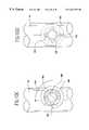
- FIGS. 2 a-bare side-sectional views of a bypass graft support structure incorporating fittings
- FIG. 2 cshows a support structure, with an attached bypass graft, thermally secured to a host vessel at two locations;
- FIGS. 3 a-cshow an end-to-end fitting that thermally secures a bypass graft to a host vessel
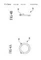
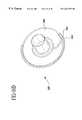
- FIGS. 4 a-ishow retaining rings used to bond the bypass graft to the fitting and/or the fitting to the vessel wall;
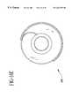
- FIGS. 5 a-eshow retaining ring embodiments that act as electrodes for thermally securing the fitting to the host vessel wall;
- FIGS. 6 a-dshow expandable retaining ring embodiments capable of serving as electrodes for thermally securing the fitting to the host vessel wall;
- FIGS. 6 e-fshow an expandable retaining ring including petals to make an end-to-end fitting able to produce an end-to-side anastomosis
- FIGS. 7 a-bshow a bypass graft everted around and attached to end-to-end fittings, and secured to the host vessel;
- FIGS. 8 a-dshow a bypass graft secured to the host vessel
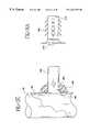
- FIGS. 9 a-cshow a delivery system
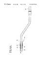
- FIG. 10shows a delivery system
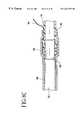
- FIG. 11shows a two-way plunger used to deliver the bypass graft and fitting combination through the sheath and into the host vessel;
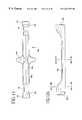
- FIGS. 12 a-cshow an alternative plunger embodiment
- FIG. 13shows a bypass graft and fitting combination being inserted through a sheath
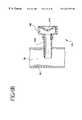
- FIG. 14shows a schematic of the system used to thermally secure a bypass graft to a host vessel wall
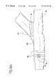
- FIGS. 15 a-eshow an end-to-side fitting that may be delivered past a vessel wall without the need for a sheath;
- FIGS. 16 a-gshow alternative end-to-side fitting embodiments that may be delivered past a host vessel wall without the need for a sheath;
- FIGS. 17 a-bshow an end-to-side fitting incorporating a retaining ring with petals
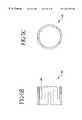
- FIGS. 18 a-gshow an end-to-side fitting for host vessels having small and medium diameters
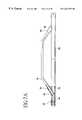
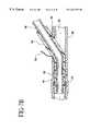
- FIGS. 19 a-fshow a foldable end-to-side fitting
- FIGS. 20 a-bshow an end-to-side fitting incorporating an electrode structure in the petals
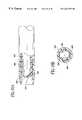
- FIGS. 21 a-dshow an end-to-side fittings having an electrode incorporated in the fitting
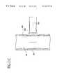
- FIGS. 22 a-bshow an end-to-side fitting containing an electrode and able to fold into a low profile
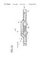
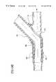
- FIG. 23shows a bypass graft and fitting combination attached to a host vessel and designed to preserve flow proximal to the anastomosis site;
- FIGS. 24 a-bare close-up views of the bypass graft and fitting combination shown in FIG. 23;
- FIGS. 24 c-hshow alternative bypass graft and fittings designed to maintain retrograde blood flow
- FIG. 25is a schematic of the system used to thermally secure the ends of the bypass graft to the vessel wall
- FIGS. 26 a-bshow an end-to-end bypass graft having an electrode incorporated in the bypass graft
- FIGS. 27 a-bshow an end-to-end bypass graft having an expandable and compressible electrode secured to the bypass graft
- FIGS. 28 a-bshow tear-away sheath embodiments
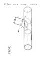
- FIGS. 29shows a fitting system
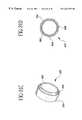
- FIGS. 30 a-dshow other embodiments of a fitting system
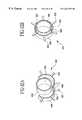
- FIGS. 31 a-dshow other embodiments of a fitting system
- FIGS. 32 a-bshow other embodiments of a fitting system.
- the fittings and delivery systemsare intended to produce anastomoses between bypass grafts and host vessels to treat vascular abnormalities such as stenoses, thromboses, other occlusions, aneurysms, fistulas, or other indications requiring a bypass graft.
- the systemsare useful in bypassing stented vessels that have restenosed.
- the fittingsare used for securing and supporting the ends of transected vessels cut during organ transplantations.
- the embodimentsalso provide mechanisms to secure branching vessels to a replacement graft during surgical procedures in which the branching vessels would otherwise be occluded from the blood flow (e.g. reattaching the renal arteries, mesenteric artery, celiac artery, and intercostal arteries during treatment of abdominal aortic aneurysms that are pararenal, suprarenal, or thoracoabdominal in classification).
- FIG. 1illustrates bypass grafts secured to host vessels during coronary artery bypass grafting (CABG) procedures.
- Bypass graft 16provides a blood flow passage from the aorta to the right coronary artery.
- An end-to-side fitting 18is used to secure the proximal end of the bypass graft 16 to the aorta and fitting 18 or end-to-end fitting 20 is used to secure the distal end of the bypass graft to the right coronary artery.
- Bypass graft 16provides a blood flow passage along a small vessel such as a coronary artery by securing the bypass graft to the host vessel with fittings 18 , 20 .
- bypass graft 16is secured to the aorta with a fitting 18 , 20 that branches into distinct bypass grafts which are further secured to the left anterior descending artery and circumflex artery using fittings 18 , 20 .
- the bypass grafts and fittings in these examplesdemonstrate representative applications and should not limit the scope of use for the embodiments of the invention. It should be noted that the combination of fittings used to secure a bypass 16 graft to a host vessel, along a host vessel, or between host vessels depends on the application.
- the bypass graft 16may be a synthetic graft material biological bypass graft, harvested vessel, or other tubular body structure, depending on the indication.
- the harvested vesselsmay be an internal mammary artery, radial artery, saphenous vein or other body tubing.
- Harvested vesselsmay be dissected using newer minimally invasive, catheter-based techniques or standard surgical approaches.
- Fittings in accordance with the inventionare designed to attach bypass grafts to host vessels (or other tubular structures).
- the fittings 18 , 20 used to position and attach such bypass grafts 16are extensions of the collet and grommet embodiments described in U.S. application Serial No. 08/966,003 filed Nov. 7, 1997.
- An advantage of biological bypass grafts over available synthetic materialsis the reduction in thrombosis, especially when using small diameter (e.g. ⁇ 2 mm) bypass grafts.
- the fittings and delivery systems of the inventionare generally equally effective at positioning and securing all types of bypass grafts, biological and synthetic.
- Synthetic bypass graftsmay be manufactured by extruding, injection molding, weaving, braiding, or dipping polymers such as PTFE, expanded PTFE, urethane, polyamide, nylon, silicone, polyethylene, collagen, polyester or composites of these representative materials. These materials may be fabricated into a sheet or tubing using one or a combination of the stated manufacturing processes. The sides of sheet materials may be bonded using radiofrequency energy, laser welding, ultrasonic welding, thermal bonding, sewing, adhesives, or a combination of these processes to form tubing.
- the synthetic bypass graftmay also be coated, deposited, or impregnated with materials, such as paralyne, heparin, hydrophilic solutions, or other substrates designed to reduce thrombosis or mitigate other risks that potentially decrease the patency of synthetic bypass grafts.
- the primary advantage of synthetic bypass graft materialsis the ability to bond the bypass graft to the fittings prior to starting the procedure or incorporate the fittings into the bypass graft design by injection molding or other manufacturing process.
- synthetic bypass graftsare indicated for blood vessels having medium and large diameters (e.g. >3 mm), such as peripheral vessels, tubular structures such as the fallopian tubes, or shunts for hemodialysis.
- medical device manufacturerssuch as Possis Medical, Inc. and Thoratec Laboratories, Inc. are clinically evaluating synthetic bypass grafts for coronary indications.
- Support membersmay be incorporated into a graft as referenced in co-pending U.S. application Serial No. 08/932,566 filed Sep. 19, 1997 and in co-pending U.S. application Serial No. 08/966,003 filed Nov. 7, 1997.
- the support membersmay be laminated between layers of graft material.
- the synthetic bypass graft 16may be fabricated by extruding, injection molding, or dipping a primary layer of the graft over a removable mandrel; positioning, winding or braiding the support members on the primary layer; and extruding, injection molding, or dipping a secondary layer over the material/support member combination.
- the support memberspreferably have a shape memory. Memory elastic alloys, such as nickel titanium, exhibiting stress-induced martensite characteristics may be used to reinforce the bypass graft and/or vessel wall and prevent permanent deformation upon exposure to external forces.
- synthetic bypass grafts 16 incorporating support membersmay be fabricated using cellulosic materials such as regenerated cellulose.
- Cellulosic materialsmay be extruded, wrapped, injection molded, or dipped in layers to laminate the support members between graft material layers.
- Cellulosics, and other such materialswhich have a high water adsorption rate, are relatively stiff when dehydrated and flexible when hydrated. This characteristic provides a means to maintain a self-expanding material such as the support members in a collapsed state.
- the cellulosic material in its dry, stiff statecounteracts the radial force of the self-expanding support members and prevents the graft from expanding until it becomes hydrated, thus more flexible.
- the cellulosic materialcontacts fluid, causing it to become more flexible and the support members of the bypass graft 16 to expand towards its resting state and the graft into intimate contact with the vessel wall.
- Biological bypass grafts 16may be reinforced with a support structure 30 as shown in FIGS. 2 a-c .
- This support structure 30may consist of a wire material wound into a helix or braided into a mesh. Other reinforcing structures that limit expansion of the bypass graft 16 may also be used.
- the support structure 30is bonded to fittings at each end by spot welding, crimping, soldering, ultrasonic welding, thermal bonding, adhesively bonding, or other bonding process, depending on the materials.
- the support structure 30defines a lumen into which the bypass graft 16 is inserted. After advancing the bypass graft 16 through the support structure 30 , the bypass graft 16 is secured to the fittings at each end of the support structure 30 .
- the support structure 30generally reduces the potential for kinking of the bypass graft 16 , limits the radial expansion of the bypass graft 16 , prevents aneurysm formation, and increases the burst strength of the bypass graft 16 .
- the support structure 30may alternatively be a synthetic graft material formed into a tube, with or without support members.
- the support structure 30may be fabricated from a polymer that is macroporous to permit blood leaking through the bypass graft to flow outside the support structure.
- Biological bypass graftstypically have branches that are sutured or stapled closed while harvesting the vessel and may leak for a period of time immediately after implantation. Blood leaking through a biological bypass graft enclosed in a nonporous or microporous (e.g.
- pore size ⁇ 8 ⁇ m support structuremay accumulate between the bypass graft and the support structure 32 and occlude the bypass graft depending on the pressure gradient between the inside of the bypass graft 16 and the space between the graft and the support structure 30 .
- nonporous or microporous support structuresmay be used.
- the support structure 30is preferably affixed to the fittings before attaching the bypass graft 16 to the fittings. This ensures the support structure reinforces the entire length of the bypass graft 16 . Using a support structure that is not affixed to the fittings may cause kinking of the bypass graft in the region between the anastomosis site and the end of the support structure, which defines a region where the bypass graft is not reinforced.
- the support structure 30incorporates fittings at each end for attachment of a harvested vessel 16 and for securing the bypass graft to the host vessel 38 . As shown in FIGS.
- a grasping tool 50including a suture with a noose or a wire with a distal gripping end such as forceps, is fed through the support structure and is used to grab the harvested vessel 16 .
- the harvested vessel 16is pulled through the support structure 30 such that a length of the harvested vessel extends beyond both ends of the support structure fittings.
- FIG. 2 cshows the ends of the harvested vessel 16 everted around the support structure fittings and secured at the notched regions 40 of the fittings using retaining rings 42 .
- Electrodes 44may be included in the support structure to thermally secure the support structure 30 and the bypass graft to the host vessel wall 39 .
- the blood flowing through the bypass graft 16contacts the endothelial layers of the harvested bypass graft and host vessel thereby minimizing the potential for thrombosis or biological reactions to foreign materials.
- the support structuresmay serve dual purposes. They may function as synthetic bypass grafts designed to produce two end-end anastomoses at opposite ends of the bypass grafts.
- the support structure/bypass graftsmay be configured with one or both ends incorporating fittings that enable end-side anastomoses. They also function as sutureless anastomosis devices to attach harvested vessels and reinforce the biological bypass grafts. This combined functionality minimizes the product portfolio required for bypass grafting indications because a single device may reinforce and facilitate attaching harvested vessels between anastomosis sites and act as a synthetic bypass graft capable of producing sutureless anastomoses.
- the bypass graft fittingsare constructed from a metal (e.g. titanium), alloy (e.g. stainless steel or nickel titanium), thermoplastic, thermoset plastic, silicone or combination of the aforementioned materials into a composite structure; other materials may also be used.
- the fittingsmay be coated with materials such as paralyne or other hydrophilic substrates that are biologically inert and reduce the surface friction.
- the fittingsmay be coated with heparin or thrombolytic substances designed to prevent thrombosis around the attachment point between the bypass graft and the host vessel.
- the fittingsconsist of one or more components designed to secure a bypass graft to the fitting and the fitting to the host vessel wall for a fluid tight bond between the bypass graft and the host vessel.
- the fittingsmay be used at end-to-end anastomoses for applications where retrograde blood flow is not essential (e.g. total occlusions) as shown in FIGS. 2 c and 8 a ; end-to-side anastomoses for medium and small diameter vessels (e.g. peripheral vessels and coronary vessels) where retrograde blood flow is essential as shown in FIG. 19 c ; and end-to-side anastomoses for large diameter vessels (e.g. the aorta) as shown in FIG. 18 a .
- the end-side fittingsmay be configured to orient the bypass graft at an angle, A, relative to the host vessel ranging between approximately 30 and 90 degrees. This helps optimize fluid flow through the bypass graft.
- FIGS. 3 a-cshow an end-end fitting 20 designed to secure bypass grafts constructed from an internal mammary artery, radial artery, saphenous vein, or other harvested vessel such that only the endothelial layer of the bypass graft is exposed to blood flow.
- the bypass graft 16is fed through the interior of the fitting and is wrapped around the distal end.
- a grasping toolmay be used to pull the bypass graft through the fitting, especially when using long fittings.
- An everting toolmay be used to wrap the bypass graft around the fitting prior to securing the bypass graft to the fitting.
- a retaining ring 62is positioned over the everted bypass graft to compress it against the fitting. This secures the bypass graft to the fitting.
- the retaining ring 62is connected to a signal wire 64 that is routed to a radiofrequency generator to deliver radiofrequency energy to the retaining ring 62 for thermal securing of the fitting to the host vessel 38 .
- FIGS. 4 a-ishow embodiments of the retaining ring 62 used to secure the bypass graft 16 to the fitting.
- the retaining ringsmay be fabricated from a metal, alloy, thermoplastic material, thermoset, composite of these materials, or other material. However, the retaining rings must permit at least 30% enlargement in diameter without becoming permanently deformed. Thus, after placement, the retaining ring will compress around the bypass graft and fitting interface to form a secure seal.
- the retaining ringis a preshaped member having a rectangular, circular, or elliptical cross-section and eyelets 63 that facilitate positioning the retaining ring over the fitting and may be used to suture the retaining ring closed for additional support.
- the retaining ring shown in FIGS. 4 a-bhas a preshaped member wound beyond a single turn.
- the diameter of the retaining ringenlarges making it easier to position over the bypass graft and fitting combination.
- the retaining ring 62is a coiled wire extending to just less than a single turn. When the eyelets 63 are spread apart, the diameter of the retaining ring enlarges.
- the retaining ring 62 shown in FIG. 4 gis a preshaped member wound beyond a single turn and having radiused edges and ends.
- One representative fabrication process for the preshaped retaining ringinvolves forming the raw material into a desired geometry and exposing the material to sufficient heat to anneal the material into this predetermined shape. This process applies to metals (e.g. nickel titanium) and polymers.
- the preshaped retaining ring configurationis expanded by inserting the expansion tool into the middle of the retaining ring and opening the expansion tool thereby enlarging the diameter of the retaining ring.
- This retaining ringmay also be used to secure a fitting to a host vessel since this retaining ring may be expanded to expose an opening between opposite ends adapted for placement over the host vessel. Once positioned over the host vessel to fitting interface, the retaining ring is allowed to return towards its preformed shape thereby compressing the host vessel against the fitting.
- the retaining ringsmay incorporate elastic memory characteristics.
- a retaining ring shown in FIG. 4 gmay be manufactured from a deformable material and crimped over the bypass graft to fitting interface or host vessel wall to fitting interface for securing purposes.
- FIG. 4 hshows another retaining ring that does not incorporate elastic memory characteristics. This retaining ring is opened for positioning around the bypass graft to fitting interface or the host vessel to fitting interface and is closed thereby causing the teeth to engage and lock the retaining ring in the closed position. Further closing the retaining ring causes the diameter to decrease and increase compression.
- FIG. 4 ishows another retaining ring 62 configuration having a preshaped member wound beyond a single turn. This embodiment also permits expansion of the retaining ring to facilitate positioning, but is configured to form a complete ring in its resting shape.
- FIGS. 5 a-e and FIGS. 6 a-fshow retaining rings 62 which are particularly useful when utilizing the thermal securing process in attaching a bypass graft and fitting to a host vessel.
- the retaining rings 62may be embedded in the bypass graft when using synthetic materials or advanced over the bypass graft and fitting interface to produce an interference fit at the bond joint.
- the retaining rings 62 shown in FIGS. 6 a-dmay be enlarged while being deployed around the bypass graft and fitting combination and allowed to return to its preformed shape, once positioned, thereby securing the bypass graft to the fitting and providing a fluid tight seal.
- the retaining rings 62have numerous edges 65 including straight notches as shown in FIG.
- the edges 65produce high current densities when radiofrequency energy is transmitted through the retaining rings.
- the retaining ring electrodeshave several spaces into which the vessel can shrink and coagulum can infiltrate thereby providing adherence between the host vessel and the retaining ring 62 .
- the retaining rings 62shown in FIGS. 6 e-f , incorporate petals 67 so that an end-to-end fitting may be used for an end-to-side anastomosis.
- the bypass graftmay be bonded to the fittings prior to securing the fittings to the host vessel. This step may be performed outside the patient to allow the physician to ensure a strong and leak resistant bond.
- Another advantage of the fittingsis that they only expose the endothelial layer of a biological bypass graft to blood flow which generally prevents thrombosis and other interactions between foreign materials and blood.
- the delivery system embodimentsare designed to access the vessel through a small puncture in the vessel wall.
- the delivery systemsare designed to prevent excess blood loss when accessing the host vessel and deploying the bypass graft and fitting combination thereby eliminating the need to stop or re-route blood flowing through the host vessel. This approach also generally improves the leak resistance around the fitting due to elastic compression of the vessel wall around the fitting and aligns the bypass graft to the host vessel wall at the anastomosis site.
- a cathetere.g. guiding member
- a puncture devicee.g. needle
- a dilating memberexpands the opening to atraumatically advance the guiding member through the vessel wall.
- a balloonmay be attached to the guiding member and inflated to restrain the guiding member outside the host vessel and to prevent leaking at the puncture site. The balloon is deflated while the guiding member is advanced through the vessel wall.
- the catheteris then manipulated to the distal anastomosis site.
- the puncture deviceis used to perforate the vessel wall and access the interior of the vessel at the distal anastomosis site.
- a guidewiremay be advanced through the puncture device or the puncture device may function as a guidewire to provide a passage to advance the guiding member into the interior of the host vessel at the distal anastomosis site.
- the bypass graftis advanced inside or outside the guiding member to the distal anastomosis site.
- a styletmay be used to advance the bypass graft along the guiding member or maintain the position of the bypass graft as the guiding member is retracted.
- the balloon attached to the guiding membermay again be inflated to keep the guiding catheter within the vessel at the distal anastomosis site and prevent leaking.
- the bypass graftis secured to the host vessel at the distal anastomosis site.
- the guiding membermay be retracted so the bypass graft is able to contact the host vessel wall at the proximal anastomosis site. If a balloon was inflated to maintain the position of the guiding member within the vessel, it must be deflated prior to retracting the guiding member through the vessel wall.
- bypass graftis then secured to the host vessel wall at the proximal anastomosis site and the guiding member is removed leaving the bypass graft as a conduit for blood to flow from the proximal anastomosis to the distal anastomosis.
- the fittings used to secure the bypass graft to the host vessel wall at the proximal and distal anastomosis sitesdepend on the application and whether retrograde blood flow through the anastomosis site is desired. Some fittings used for end-to-end anastomoses may not permit retrograde blood flow.
- FIGS. 7 a-bshow fittings 60 attached in-line along a vessel 38 .
- the fittings 60are designed to support the bypass graft at the vessel wall insertion site 90 and prevent the host vessel 38 from constricting the diameter of the bypass graft 16 .
- the bypass graft 16is advanced through the fitting 60 and is everted around the distal end of the fitting 60 .
- a retaining ring 42is used to secure the bypass graft 16 to the fitting 60 and is positioned within the notched region 40 .
- the bypass graftmay be secured to the vessel by transmitting radiofrequency energy to electrodes 44 attached to the bypass graft 16 .
- the electrodes 44may be conductive fittings or retaining rings bonded to the bypass graft as previously described.
- the electrodes 44may be fabricated from stainless steel, nickel titanium, platinum, platinum iridium, gold, titanium, tungsten, tantalum, or other material and may provide structural support to the bypass graft. Electrodes 44 may be incorporated into the fittings to thermally secure the fitting and the bypass graft to the vessel wall at each anastomosis.
- the retaining ringsmay serve to bond the bypass graft to the fitting and act as the electrodes for thermal securing.
- the electrodesmay be added to the fitting as separate components aside from the retaining rings.
- the electrodesWhen fittings are laminated within layers of synthetic bypass graft material eliminating the need for retaining rings, the electrodes will be bonded to the fittings or bypass graft during manufacturing.
- These end-to-end fittingsare particularly useful when performing in-line anastomoses along a vessel and around a vascular abnormality. They are also useful to treat total occlusions when retrograde blood flow is not beneficial.
- the delivery system of the surgical approachmust permit removal after both ends of the bypass graft have been secured and the delivery system resides around the attached bypass graft.
- FIGS. 8 a-dshow that the bypass graft 16 does not need to be everted.
- synthetic bypass graftsmay be attached to the exterior of the fitting 65 .
- the fitting 65may be laminated between layers of the bypass graft 16 .
- FIGS. 9 a-cshow steps to position a bypass graft and fitting combination through a vessel wall 39 .
- a needle 100is inserted through a dilator 102 and a sheath 104 .
- the needle, dilator, and sheath combinationis positioned at the target vessel location.
- sensorsmay be incorporated in the needle, dilator, and/or sheath to position the delivery system at the target location.
- the sensorscan include ultrasonic transducers, such as those fabricated from piezoelectric material, doppler crystals, infrared transducers, or fiberoptics.
- a lumenmay permit the injection of radiopaque contrast material within the vessel to verify the position using fluoroscopy.
- FIG. 9 aillustrates needle 100 being used to puncture the vessel wall 39 and advancing into the interior of the vessel 38 .
- the needle 100may be designed with a tapered or stepped distal end to restrict movement of the needle beyond the end of the dilator 102 and prevent perforating the opposite side of the vessel or unwanted anatomy.
- a guidewire(not shown) may be advanced through the needle to provide a path over which the dilator and sheath may be advanced. When using a guidewire, the needle may be retracted to prevent unwanted perforations or abrasions to the vessel or adjacent anatomy. The dilator 102 is then advanced over the needle 100 or guidewire into the host vessel.
- the needle 100(if not already retracted to insert the guidewire) may be removed from the vessel or retracted inside the dilator 102 .
- the dilator 102is tapered to provide a smooth transition when advancing through the vessel wall 39 .
- the vessel wall 39forms a seal around the dilator 102 to preventing excess blood leakage from the vessel.
- a sheath 104 having a radius or tapered distal endforms a smooth transition around the dilator 102 .
- Insertion of a sheath 104 into a vessel 38 over a dilator 102 and needle 100is commonly used by physicians when performing the Seldinger technique during catheterization procedures or inserting I.V. catheters into veins for withdrawal of blood or introduction of medicines.
- the sheath 104 and dilator 102may be constructed from polyethylene, or other polymer and be extruded or molded into a tube.
- the sheath 104 and dilator 102may incorporate a braided layer laminated between two polymers to resist kinking and improve the column strength and torque response.
- a taper and radiusmay be formed in the distal end of the dilator and sheath by thermally forming the raw tubing into the desired shape.
- the hub 106 , 108 on the sheath 104 and dilator 102may be fabricated from polycarbonate, polyethylene, PEEK, urethane or other material and be injection molded, adhesively bonded, or thermally bonded to the tube.
- the hub 106contains at least one and preferably two grooves, slits, or series of perforations along the hub to enable the operator to split the hub when removing the sheath from around the bypass graft.
- the hub 106houses a hemostatic valve 110 constructed of silicone or other material having a large percent elongation characteristic. The hemostatic valve 110 prevents excess blood loss through the sheath when positioned into the vessel.
- the valve 110also incorporates at least one groove, slit, or series of perforations to permit separation when tearing the sheath from around the bypass graft.
- a side portmay be included to aspirate and flush the sheath.
- the hubmay alternatively be a separate piece from the tear-away sheath and be independently removed from around the bypass graft.
- This hubmay include a luer fitting to enable screwing onto a mating piece of the tear-away sheath, or other mechanism to permit removable attachment of the hub to the tear-away sheath.
- This hubmay incorporate at least one groove, slit, or series of perforations to enable splitting the hub to form an opening to remove the hub from around the bypass graft.
- the hubmay include a slot which may be closed to prevent fluid leaking and may be aligned to form an opening for removal from around the bypass graft.
- the needle 100 and dilator 102may incorporate a number of additional features to facilitate positioning at the host vessel.
- a number of sensorsmay be placed within the tapered region of the dilator such that they face axially or laterally with respect to the axis of the dilator lumen.
- imaging modalitiesmay be directed forward or around the periphery of the dilator.
- the sensorsmay be oriented around the dilator 102 at known angular increments.
- Sensors used to position the delivery systeminclude ultrasonic transducers, such as those fabricated from piezoelectric material, infrared transducers, or fiberoptics.
- ultrasonic transducersmay be placed around the dilator 102 separated by 90 degrees to provide a 3-dimensional interpretation of anatomic structures in front of the dilator to better detect the host vessel.
- Conventional phased array imaging modalitiesmay be used to derive images extending distal to the dilator 102 or around the circumference of the dilator 102 .
- Sensorsmay be placed at the distal end of the needle 100 to facilitate positioning the needle at vessel location. The sensors may be used with the dilator sensors to provide better imaging resolution and determine the location of the needle tip relative to the end of the dilator 102 .
- a steering mechanismmay be positioned within the sheath, dilator, and/or needle.
- the steering mechanismmay include a pull-wire terminating at a flat spring or collar in the sheath, dilator, or needle.
- the steering systemhas a more flexible distal section compared to the proximal tube body. When tension is placed on the pullwire, the sheath, dilator, or needle is deflected into a curve which helps direct the delivery system to the target vessel location.
- the pullwiremay be wound, crimped, spot welded or soldered to the flat spring or collar placed in the sheath or dilator.
- the pullwiremay be spot welded or soldered to one side of the needle hypotubing.
- the proximal tube body of the sheath or dilatormay be reinforced by incorporating a helically wound wire within the tube extrusion to provide column support from which to better deflect the distal section.
- FIG. 10shows sheath 118 with at least one groove 120 , slit, or series of perforations formed along the tube and hub 122 to provide a tear-away mechanism along at least one side for use after securing the bypass graft to the vessel wall.
- the sheath 118may include a section of tubing material pre-split into at least two sections such that the tubing tends to continue to split into two pieces as the sections are pulled apart. This feature is essential for removal of the sheath 118 from around a bypass graft 16 when the sheath 118 is unable to slide past the opposite end of the bypass graft 16 . Support material incorporated into a tear-away sheath to improve column strength should split along the grooves formed in the sheath.
- the support materialmay be fabricated into two braided sections oriented on opposite sides of the sheath such that the grooves reside along the spaces between the braided sections.
- the supporting materialmay be strands of wire (e.g. stainless steel, nylon, etc.) laminated between layers of sheath material and oriented axially along the longitudinal axis of the sheath.
- the tear-away sheath 118may further incorporate features to maintain blood flow through the host vessel while positioned inside the lumen of the host vessel as further referenced in FIGS. 28 a-b.
- the plunger 124is designed to insert the bypass graft 16 and fitting 130 as an attached unit and includes a lumen to pass the bypass graft 16 through while inserting the fitting 130 into the host vessel.
- a plunger 124is essential when inserting biological bypass grafts or synthetic bypass grafts that do not have adequate column strength to be pushed through the hemostatic valve of the sheath.
- the plunger 124protects the bypass graft during insertion through the hemostatic valve of the sheath. After one side of the bypass graft is placed at a first vessel location, the plunger 124 must be removed.
- the plunger 124may be retracted beyond the opposite end of the bypass graft, if possible, or the plunger 124 may be split along at least one groove 120 , 126 incorporated along the side of the plunger.
- the plunger 124is used to insert the opposite end of the bypass graft, attached to a fitting, through a second sheath inserted at a second vessel location. After attaching the second end of the bypass graft to the vessel, the plunger 124 is contained between the ends of the attached bypass graft and must be removed by tearing the plunger along at least one and preferably two grooves 120 , 126 .
- the tear-away groove 120 , 126must permit splitting the plunger wall and hub 128 along at least one side to remove the plunger 124 from around the bypass graft.
- the plunger 124 and tear-away sheath 118 discussed abovepreferably incorporate grooves, slits, or perforations 126 on two sides to enable separation into two components.
- FIG. 11shows a bypass graft assembly containing fittings 60 already attached at the bypass graft 16 ends and plunger 140 preloaded onto the bypass graft 16 .
- This plunger 140is designed with the hub 142 located at the middle region to facilitate insertion of both ends of the bypass graft and attached fittings without removal and repositioning of the plunger prior to insertion of the second end of the bypass graft.
- the plunger 140has grooves, slits, or perforations 126 along at least one side of the plunger tube 144 and hub 142 to permit removal after positioning and attachment of the bypass graft at both ends.
- FIGS. 12 a-cillustrate another plunger embodiment.
- Plunger 150includes an axial slot through its entire length. The slot enables pulling of the plunger 150 from the side of the bypass graft when removing the plunger and permits pressing of the plunger 150 over the side of the bypass graft when placing the plunger over the bypass graft.
- One end 152has a short length stepped down to form a smaller outer diameter that fits inside the inner diameter of the fitting and provides a stable anchor to insert and manipulate during delivery of the bypass graft and fitting combination into the vessel.
- the other end 154has the inner diameter reamed out and notched for a short length to fit over the outer diameter of the bypass graft and fitting combination during manipulations.
- the plunger 150maintains its integrity upon removal from the bypass graft and may be used to deploy multiple bypass graft and fitting combinations through sheaths.
- FIG. 13is an enlarged view of sheath 172 inserted into host vessel 39 with dilator removed, and with bypass graft 16 everted about fitting 170 and retained by ring 174 .
- a modified hockey stick introducermay be used to insert the bypass graft and fitting combination into the host vessel.
- the hockey stick introducerhas a tapered distal end and a partially enclosed body. This introducer is advanced through the incision and is used to expand the vessel wall so the bypass graft and fitting combination may be advanced through the lumen of the introducer and into the host vessel without catching the top part of the fitting on the vessel wall. This is especially important when the bypass graft and fitting combination has an outer diameter larger than the inner diameter of the vessel where the host vessel must be expanded to insert the bypass graft and fitting combination.
- the introducermay incorporate an extension perpendicular to the longitudinal axis that provides a handle to manipulate the introducer.
- FIG. 14shows electrodes 181 including conductive material bonded to the bypass graft or fitting 180 .
- the electrodes 181are used to transmit energy to the vessel wall and may be deposited (e.g. ion beam assisted deposition, sputter coating, pad printing, silk screening, soldering, or painting conductive epoxy) on the fittings 180 , bypass graft 16 or retaining ring 182 .
- the electrodes 181may be flexible and follow the contours of the fittings and/or bypass graft.
- the electrodesmay be formed in a helix, mesh, or braid and bonded to the exterior surface of the fitting and/or bypass graft.
- Signal wires 183 and 184are connected to the electrodes through spot welding, mechanical fit, or soldering, and are routed to the leads of a radiofrequency generator 186 .
- a large surface area indifferent ground padmay be placed on the patient's back, thigh, or other location so radiofrequency energy may be delivered in a unipolar configuration. Alternatively, energy may be delivered between electrode pairs in bipolar configuration.
- tissue contacting the electrodesheats and coagulates the vessel wall to the electrode and provides a secure, leak resistant bond.
- a dramatic increase in impedanceresults from the formation of coagulum on the electrode.
- This measurement of the bond strengthcan be used to determine the quality of the bond generated between the electrode 44 and the vessel wall 39 .
- Different impedance thresholdsmay specify different degrees of thermal bonding. Initial thermal bonding has been demonstrated during experimental studies when impedance increased above 300 ⁇ using a signal frequency of 500 kHz, which represented a threshold approximately 50% above baseline. The baseline impedance differs depending on the frequency of the signal and the surface area of the electrode; these characteristics must be taken into account when determining the thresholds.
- Commercial electrosurgical generators operating at a frequency of approximately 500 kHzcommonly measure impedances up to and exceeding 1 k ⁇ when producing complete hemostasis using tissue coagulating probes.
- FIGS. 15 a-eshow a system for producing an end-to-side anastomosis that compresses the vessel wall between two fitting components.
- the fitting 196incorporates a flared distal region 190 having a slot 192 that defines two edges.
- the slotted distal end of the fittingis inserted through a puncture 194 of the vessel wall 39 by positioning the edge of the slotted fitting at the puncture site 194 , angling the distal flared region 190 so the edge may be further advanced through the vessel wall, and rotating the fitting 196 .
- the entire flared region of the fittingis advanced into the interior of the vessel 38 , as shown in FIG. 15 d .
- a compression ring 198is positioned over the fitting 196 and past the tabs 200 to compress the vessel wall 39 between the flared distal end 190 and the compression ring 198 .
- FIGS. 16 a-cshow fitting 210 including edge 212 at a flared end, and a slotted region to ensure a fluid tight fit after deployment and securement of the fitting 210 to a vessel with a compression ring (not shown).
- the lower edgeis advanced through the puncture site 214 , and the fitting 210 is rotated to advance the distal, flared end of the fitting into the vessel.
- a compression ringis advanced over the fitting 210 and is locked in place with the tabs 200 thereby securing the vessel wall between the distal, flared end of the fitting and the compression ring.
- the fitting 210includes multiple rows of tabs 200 to accommodate various sized vessel walls. This feature is important when treating vascular diseases associated with thickening of the vessel wall.
- FIGS. 16 d-eshow fitting 220 .
- a guidewireis inserted through the vessel wall and into the interior of the host vessel by puncturing the vessel wall with a needle and inserting the guidewire through the lumen of the needle.
- the needleis removed from around the guidewire after inserting the guidewire through the vessel wall.
- An insertion tubing 222 containing a central lumen 224follows the periphery of the flared end 226 and is adapted to pass a guidewire.
- the guidewireis fed through the insertion tubing 222 to facilitate the screwing of the fitting past the vessel wall.
- the insertion tubing 222extends approximately 40% to 80% around the flared end circumference.
- the insertion tubing 222may be configured in sections extending around the circumference of the flared end such that a physician may determine how far around the flared end the guidewire must extend in order to rotate the flared end past the host vessel wall.
- a slot 228 through the distal flared endis adapted to accept the thickness of the vessel wall and enables the screwing of the fitting through the vessel wall.
- the fitting 220As the fitting 220 is advanced over the guidewire and rotated, the fitting 220 simultaneously expands the puncture through the vessel wall and inserts more of the distal flared end into the vessel interior.
- the guidewireis removed and the fitting 220 is secured to the vessel wall using a compression ring and/or thermal securing.
- thermal securingthe distal flared end (at least the side facing the vessel wall) is made conductive and is attached to an energy source to heat the vessel and to thermally secure the fitting 220 to the vessel wall.
- the fittingsmay be configured to incorporate electrodes to facilitate thermal securing of the fitting to the vessel wall.
- the electrodesmay be fabricated from stainless steel, nickel titanium, platinum, platinum iridium, gold, titanium, tungsten, tantalum, or other conductive material and may also be fabricated to provide structural support to the bypass graft.
- the electrodesmay be deposited (e.g. ion beam assisted deposition, sputter coating, solder, silk screen, pad printing, painting conductive epoxy, or other process) on the fittings and/or bypass graft such that the electrodes are thin and flexible and follow the contours of the fittings and/or bypass graft.
- the thermal securing propertiesmay be the only attachment means required to provide a fluid tight bond between the fitting and the vessel wall.
- thermal securingmay be augmented by attaching a compression ring as described above, applying adhesives to the bond, or suturing the fitting to the vessel wall. After securing the bypass graft to the fitting and advancing the fitting into the host vessel, the bypass graft and fitting combination may be attached to the host vessel wall.
- FIGS. 17 a-bshow a fitting 240 for performing an end-to-side anastomosis.
- a bypass graft 16is everted over the distal end of the fitting 240 .
- a retaining housing 242similar to that shown in FIGS. 6 e-f , is used to secure the bypass graft to the fitting.
- This retaining housing 242permits radial expansion during placement over the bypass graft 16 and fitting and has a preshaped memory to compress around the bypass graft and fitting 240 to secure the bypass graft.
- This retaining housing 242has petals 244 at its distal end, which compress into a low profile during delivery through a sheath and expand radially once deployed into the vessel 38 .
- the number of petals 244depends on the size of the bypass graft and the size of the host vessel. In this embodiment, eight petals are used. After advancing the fitting through a sheath, the fitting is advanced beyond the end of the sheath and is no longer constrained by the sheath, and expands towards its resting configuration. Then the bypass graft and fitting combination is gently retracted to engage the interior vessel wall at the petals 244 . For mechanical securing, a compression ring 246 is advanced over the fitting thereby compressing the vessel wall 39 between the petals 244 of the retaining housing and the compression ring 246 .
- the retaining housingmay incorporate a threaded mechanism 248 to screw on the compression ring and secure the compression ring relative to the retaining housing.
- the threadsare oriented only along the sections of the retaining housing configured to engage the compression ring.
- the slotted regions enabling the retaining housing to radially expand and collapsedo not include threads.
- the compression ring 246is alternatively locked in place using a screw mechanism, a ratchet mechanism, adhesives, sutures, or other attachment means to secure the compression ring in place.
- the compression ring 246incorporates two components: 1) a distal, flexible o-ring or disk 250 designed to produce a fluid tight seal and prevent damaging the vessel wall by excess compression; and 2) a proximal, more rigid locking ring 252 used to maintain the position of the o-ring or disk relative to the vessel wall.
- the locking ring 252is designed to match the threads incorporated in the retaining housing. Mechanical securing may be replaced or augmented with thermal securing.
- FIGS. 18 a-gshow a fitting 260 used to produce an end-to-side anastomosis, especially for medium to small diameter vessels (e.g. peripheral vessels and coronary vessels).
- medium to small diameter vesselse.g. peripheral vessels and coronary vessels.
- FIG. 18 afour petals are collapsed into a low profile for insertion through a sheath 262 during deployment into the vessel. Once positioned, the sheath 262 is retracted enabling the petals to expand toward their resting shape.
- This fitting 260includes two petals 264 designed to extend axially along the vessel and pre-formed to contact the host vessel wall.
- the fittingalso includes two other petals 266 and 268 designed to extend radially around a portion of the vessel.
- the petalsprovide a structure to prevent the fitting from pulling out of the vessel, restrict rotation of the fitting relative to the graft, ensure the host vessel does not collapse or constrict at the anastomosis site, and provide a support to compress the vessel wall between fitting components.
- the petals 266 and 268may be configured to return to a closed configuration in their resting state, as shown in FIG. 18 f .
- the petals 266 and 268may be configured to expand beyond the closed configuration in their resting state, as shown in FIG. 18 e . This configuration helps the fitting petals exert radial force on the host vessel to better support the fitting within the host vessel and keep the host vessel open at the bond interface.
- These end-side fittingsmay alternatively include more than 4 petals.
- 18 gshows an end-side fitting having two axially oriented petals, 270 and four radially oriented petals, 272 .
- the petals, 270 , 272are configured to expand beyond the closed configuration in their resting state; alternatively, the petals may be configured to return to a closed configuration in their resting state.
- the fittings that produce end-to-side anastomosesmay be configured to produce an angle (A) between the bypass graft 16 and the interior of the host vessel 38 .
- FIGS. 19 a-fshow an end-to-side fitting 290 that may be folded to insert through a sheath with a smaller diameter than the fitting.
- the foldable fitting 290may be fabricated from a sheet of metal material that has been chemically etched, EDM, or laser drilled into the pattern shown. The opposite ends 295 and 297 of the fitting 290 match so they may be bonded together to form the expanded cross-section shown in FIG. 19 c .
- the fittingmay be fabricated from a tubular metal material using chemical etching, EDM, laser drilling, or other manufacturing process to form the desired pattern.
- the petals 292are preshaped to expand radially outward once they have been deployed outside the introducing sheath. In this configuration the vessel wall can be compressed between the petals 292 and a compression ring.
- the fittingis designed to fold into a reduced diameter during deployment and expand toward its resting shape once positioned through the introducing sheath.
- the fittingincludes links 294 that are fabricated by reducing the thickness or width of the fitting material and act as hinges for the fitting to fold into a low profile.
- the foldable fitting embodiment shown in FIGS. 19 a-fis designed with 6 sides connected with links 293 , 294 so two adjacent sides are able to fold inward thereby reducing the diameter for insertion through the delivery system.
- the foldable fittingmay further be configured so two more adjacent sides at the opposite end of the initially folded sides are able to fold inward and further decrease the profile for insertion through the delivery system.
- the foldable fittingmay alternatively have more than 6 sides and be configured so multiple adjacent sides fold inward to reduce the profile for introduction.
- the foldable fittingincorporates a synthetic graft material 296 that is extruded, injection molded, or dipped onto the fitting 290 .
- the manufacturing processcauses the graft material to fill slots and holes 298 cut in the fitting 290 .
- Thisproduces a more reliable bond between the synthetic graft material and the expandable, foldable fitting.
- the covered fitting 290will expand and fold as long as synthetic graft materials having a high percent elongation characteristic is chosen.
- the graft materialmay stretch along the folds incorporated in the fitting.
- a biological bypass graft(e.g. harvested vessel) may be sutured to the holes 298 incorporated in the fitting.
- this fitting 290may also be used to fabricate end-to-end fittings by excluding the petals from the design.
- the foldable support structuremay extend throughout the length of the bypass graft and be configured so that the sides rotate around the bypass graft at specific points to increase the axial flexibility but maintain the potential to fold into a reduced diameter.
- FIGS. 20 a-bshow an end-to-side fitting 310 having petals, and containing exposed electrodes 312 on the outside surface of the petals facing the vessel wall once deployed.
- a signal wire 314is spot welded, crimped, attached using conductive adhesives, or soldered to provide an electrical connection between the electrodes 312 of the petals and a radiofrequency generator (not shown).
- the fitting 310is fabricated by extruding, injection molding, or otherwise applying a nonconductive, conformal coating (e.g. elastomer) over an electrode structure 316 configured to include petals.
- a nonconductive, conformal coatinge.g. elastomer
- the outside surfaces of the petalsare removed exposing the electrodes 312 .
- the petalsare preshaped so the outside surfaces defining the electrodes contact the vessel wall, once deployed. As shown in FIG.
- a conduction ring 318is placed into contact with the electrode structure 316 on the proximal end of the fitting and is bonded in place.
- a signal wire 314used to transmit radiofrequency energy from a generator, is bonded to the conduction ring 318 .
- radiofrequency energy transmitted to the conduction ring 318will be routed to all electrodes positioned on the petals simultaneously.
- individual signal wires 314may be attached to each petal electrode 312 and routed to a generator to independently energize each electrode.
- the signal wire 314may be fabricated from platinum, stainless steel, or a composite of materials (e.g. platinum and silver combined by a drawn filled tubing process).
- the composite signal wireuses the silver as the inner core to better transmit RF energy to the electrode and platinum to ensure biocompatibility.
- the signal wiresmay be fabricated with a circular, elliptical, rectangular (flat), or other geometry depending on the design of the electrode and space available in the delivery system. After thermal securing the bypass graft to the host vessel, the signal wire may be mechanically severed near the electrical connection using a pair of dikes.
- the signal wire 314may incorporate a notch designed to separate when exposed to a desired amount of tension or torque, less than that required to dislodge the thermally secured bypass graft.
- the wirecan be separated by transmitting pulses of radiofrequency or direct current energy through the signal wire capable of ionizing the signal wire and causing breakdown of the material.
- a notchmay be incorporated in the signal wire to localize the breakdown point along the signal wire.
- FIGS. 21 a-bshow an end-to-side fitting 330 incorporating an electrode structure 332 for thermally securing the fitting 330 to the vessel wall 39 .
- the fitting 30has a flared distal end with at least one electrode 332 exposed along the outside surface of the fitting.
- a signed wire 333 to transmit radio frequency energy from a generatormay be attached to electrode 332 .
- the at least one electrode 332extends around the fitting 330 and has axial extensions adapted to orient the fitting along the vessel wall. The extensions provide an additional support structure to prevent rotation of the fitting relative to the vessel and reinforce the bond by using a mechanical securing mechanism such as a compression ring or other suitable means.
- the fitting 330is manufactured from a polymer dipped, deposited, coated, or injection molded over a conductive structure such that only the distal outside surface of the conductive structure is exposed. The electrical connection will be established prior to dipping or injection molding of the fitting.
- the distal end of the flared electrode structurehas a detent 334 to better secure the elastomer material to the electrode structure 332 .
- the flared end of the fitting 330must be flexible enough to be gathered into a low profile for introduction through a sheath and must have enough stiffness to contact the vessel wall and produce a fluid tight seal once secured in place.
- FIGS. 21 c-dshow another end-to-side fitting 330 incorporating an electrode 332 .
- This embodimentincludes an elastomer or other coating 336 around the distal, flared end of the electrode 332 .
- the electrode 332is configured with petals 338 that collapse during deployment of the fitting into the vessel.
- the elastomer coating 336masks the blood flow, maintains the collapsibility of the fitting, and helps ensure a fluid tight bond between the fitting and the vessel wall.
- the electrode 332is exposed on the outside surface of the distal, flared end of the fitting.
- the electrode 332provides mechanical support to the fitting and enables thermal securing of the fitting 330 to the vessel wall 39 .
- FIGS. 22 a-bshow an end-to-side fitting 350 incorporating an electrode structure 332 that enables the fitting to collapse into a low profile for insertion through an introducing sheath having a smaller diameter than the fitting 350 .
- the distal flared end of the electrode structure 351compresses forward and the body of the fitting folds into a low profile for insertion through a sheath. Once deployed outside the sheath, the fitting 350 returns to its expanded, resting configuration. The flared, distal end contacts the interior surface of the vessel wall and provides a structure to compress the vessel wall using a compression ring.
- the electrode structureis fabricated from a conductive material (preferably but not limited to memory elastic materials) braided over a thermoplastic, thermoset plastic, silicone, or other material and is formed into a preshaped configuration having a flared end.
- the braided electrode structuremay alternatively be composed of a memory elastic material such as nickel titanium for providing structural support intertwined with a good conductor such as platinum. Additionally, the braided material may be deposited with a conductive material to increase conduction. Since the electrode structure 351 is braided, the distal end of the electrode structure 351 is coated with an elastomer or other material 352 to prevent unraveling of the braided material. This electrode structure 351 may also used to thermally secure the fitting to the vessel wall once radiofrequency energy is transmitted to the electrode structure from a generator.
- FIG. 23shows an end-to-end fitting 370 that permits retrograde blood flow through the anastomosis site.
- the fitting 370has holes 372 through the angled sections of the fittings to preserve fluid flow through the vessel distal and/or proximal, depending on the location of the fitting within the host vessel.
- the bypass graft and fitting combination 374after deployed within and attached to the vessel maintains blood flow through the stenosis as well as establishes a passage around the lesion 376 .
- the fitting 370maintains blood flow to branching vessels proximal to the anastomosis site.
- FIGS. 24 a-bshow fitting 370 attached to the vessel at two locations.
- the fitting 370is placed within the vessel and contacts the interior surface of the vessel along a substantial length.
- FIG. 24 bshows that the fitting 370 may incorporate barbs 382 to prevent axial dislodgment of the fitting from the host vessel 38 .
- the barbsmay also provide a support to secure a retaining ring or suture to mechanically secure the fitting to the host vessel.
- a second attachmentis located at the insertion site through the vessel wall 39 .
- a compression ring or retaining ringmay be used to compress the vessel wall 39 around the fitting 370 and prevent fluid from leaking at the insertion site.
- Electrodesmay additionally or alternatively be positioned around the fitting at the insertion site 384 and/or at the distal end 386 of the fitting to thermally secure the fitting to the vessel wall and provide a fluid tight bond.
- the electrodesmay be fabricated from stainless steel, nickel titanium, platinum, platinum iridium, gold, titanium, tungsten, tantalum, or other material and may also be fabricated to provide structural support to the bypass graft.
- the electrodesmay be deposited (e.g. ion beam assisted deposition, sputter coating, pad printing, silk screening, soldering, or painting conductive epoxy) on the fittings and/or bypass graft such that the electrodes are flexible and follow the contours of the fittings and/or bypass graft.
- Fitting 370is particularly useful for medium size diameter vessels (>3 mm) where synthetic bypass grafts are used to supplement the blood flow through the vessel or shunt the blood flow to other vessels or organs.
- FIGS. 24 c-hshow additional end-end fitting embodiments that permit retrograde blood flow.
- the fitting 380incorporate a modification to provide a short proximal extension that contacts the vessel wall along the insertion site at the host vessel. This provides a structure to attach a compression ring and produce a fluid tight bond at the insertion site.
- a locking mechanismis incorporated in the fitting design to enable securing a compression ring to the fitting.
- FIGS. 24 e-fshow the fitting 380 may incorporate two electrodes, 388 , 390 around the distal end and proximal extension of the fitting. An electrode may also be located around the leg of the fitting located at the insertion site.
- the electrodes, 388 , 390may incorporate holes to improve thermal securing of the electrodes to the host vessel wall.
- FIGS. 24 g-hshow another end-end fitting 385 that permits retrograde perfusion and incorporates electrodes, 392 , 394 around the distal end and proximal extension of the fitting.
- This fittingalso includes two separate lumens.
- Lumen 396connects blood flow from the bypass graft 16 to the host vessel.
- Lumen 398connects blood flow between regions of the host vessel proximal to the anastomosis site and distal to the anastomosis site.
- the inventions described in this patent applicationdescribe embodiments that permit thermally securing bypass grafts to host vessels.
- the inventionsrequire localized transmission of energy to precisely heat the interior surface of the host vessel and a support structure to maintain contact between the bypass graft and host vessel during and after the thermal securing process.
- the coagulation of tissue and shrinkage of blood vesselsresults from the application of heat and thermally secures the bypass grafts to the host vessel.
- thermal securing mechanisms as shown in FIGS. 14 and 25is used to increase the strength of the mechanical bond, and ensure a fluid tight seal between the bypass graft and host vessel.
- thermal securingmay be solely used to bond the bypass graft fitting to the vessel wall. This feature may be adapted to all fittings. Thermal securing is accomplished by coagulating tissue to the electrodes and is enhanced by an induced shrinking of the heated tissue region producing an interference fit between the vessel and the fitting. These physiologic responses to heating produce a secure bond between the electrode and the vessel wall and prevent leaking around the fitting.
- Coagulating tissue to thermally bond a patch of porous material to the external surface of tissuehas been described by Fusion Medical Technologies, Inc. (U.S. Pat. Nos. 5,156,613; 5,669,934; 5,690,675; 5,749,895; and 5,824,015).
- a sheet of collagen or similar porous materialis placed over tissue and sufficient energy from a radiofrequency inert gas source is delivered over the patch to form coagulum at the tissue surface.
- the coagulumfills the pores of the external patch and cools to form a bond thereby producing hemostasis between the tissue and the external patch.
- the Fusion Medical productis suited for applications such as lung resections or reattaching transected vessels where direct exposure to the wound enables positioning the patch over the external surface of the tissue, and an energy source may be used to grossly apply heat over the exterior of the patch.
- FIG. 25shows a schematic for a bypass graft 16 incorporating two end-to-end fittings and containing electrodes 400 designed to thermally secure the bypass graft to the vessel wall.
- the electrodes 400are secured to the fitting and are bonded to signal wires, 402 and 404 , which are routed to a generator 406 .
- Radiofrequency or d.c. currentis transmitted to the electrodes unipolar to an indifferent ground patch electrode 408 placed on the patient, or bipolar between the electrodes.
- Electrodesenhance the heating response and improve the bonding between the electrodes and the vessel wall.
- Contact between the electrode and the vesselis important to ensure an adequate bond when thermally securing the electrode to the vessel wall.
- the outer diameter of the electrode in its expanded configurationshould exceed the inner diameter of the host vessel to ensure adequate contact between the vessel wall and the fitting.
- FIGS. 26 a-bshow an end-to-end fitting 420 incorporating an electrode 422 into the design.
- the fitting 420collapses into a low profile during insertion into the vessel and expand towards its resting state upon deployment into the vessel.
- Such an expandable, collapsible fittinghelps ensure contact between the electrode 422 and the vessel wall despite any mismatching of the bypass graft size to that of the host vessel.
- the fittingmay be extruded in a multi-layer configuration.
- the electrodemay be braided into a mesh over an initial polymer layer 426 .
- a second polymer 428may be extruded, injection molded, or dipped over the braided first layer. To expose the electrode 422 , a section of the outer layer is removed.
- the section of exposed electrodemay be masked when extruding, injection molding, or dipping the outer layer.
- a signal wire 424is bonded to the braided mesh, before or after fabricating the outer layer, to produce an electrical connection that is routed to a generator.
- FIGS. 27 a-bshow a bypass graft incorporating an electrode 430 that is designed to collapse into a low profile during deployment and expand to contact the vessel wall once inserted into the vessel.
- the electrode 430is attached to a signal wire 432 , which is used to connect the electrode to a generator 434 .
- This electrode 430is fabricated from a mesh of memory elastic material formed over an initial polymer layer 436 , and preshaped to have an expanded region as shown.
- the regions proximal and just distal to the expanded electrodehave a tubular shape and are coated with a thermoplastic or thermoset insulative material 438 . This process forms a fitting incorporating an expandable, collapsible electrode that does not change the inner diameter of the bypass graft during or after deployment.
- Another important feature to thermally secure a fitting to a host vesselis the current density profile transmitted from an electrode to tissue.
- the configurations of the expandable retaining ringspreviously discussed in FIGS. 5 a-d and FIGS. 6 a-d , make them more effective at thermally securing the retaining ring (electrode) and the bypass graft and fitting combination, to the vessel wall.
- These electrodesare designed with edges at the holes, notches, and slots cut in the ring. These holes, notches, and slots may be fabricated by laser drilling, EDM, milling, or other manufacturing process. Deposited electrodes, when used, may be applied in patterns that contain numerous edges. When radiofrequency energy is transmitted to these electrodes, the edges produce high current densities that locally heat the vessel wall.
- the small cross-sectional diameters of the conductive material forming the retaining ringsensures minimal depth of penetration, maintains focuses heating of the vessel wall, and helps to prevent damage to adjacent anatomy.
- the spaces defined by the electrode holes, notches, and slotsprovide a place for the vessel to shrink and coagulate. This increases the bond strength between the electrode and the vessel wall.
- the electrodesmay additionally be covered with a porous material, such as collagen, fibrinogen, gelatin, and urethane, to further define a structure incorporating holes, notches, and slots for tissue to shrink and coagulate.
- the use of materials containing holes, notches and slotsmay also be used to encourage neointimal cell growth.
- Porous materials having a low melting pointe.g. 60° C.-120° C.
- Heating such porous materialscauses them to soften, reform and/or crosslink to coagulated tissue while heating the vessel wall with the electrodes.
- electrodesmay also be incorporated in the end-to-side fittings.
- the electrode features described above which improve thermal securingmay be incorporated in the petals or flared regions of the end-to-side fittings. These features are designed to increase contact between the electrode and the interior of the vessel wall, provide a structure to localize bonding between the vessel wall and the electrode, and insulate the electrodes from blood flow.
- FIG. 28 ashows cut-out areas 450 oriented along the tear-away sheath 452 and distributed radially around the sheath 452 that permit blood to flow through the cut-out areas in the sheath and past the distal lumen of the sheath.
- Alternative distributions and geometries for the cut-out areasmay be chosen based on application and insertion requirements for the bypass graft.
- FIG. 28 bshows a tear-away sheath incorporating an anchoring extension 454 at the distal end of the sheath. The extension 454 is designed to maintain access between the tear-away sheath and the host vessel when the sheath is positioned perpendicular to the host vessel.
- the length of the sheathshould be limited to that required to access the interior of the host vessel while ensuring short bypass grafts may be inserted past the distal end of the sheath, especially when the bypass graft has been secured at the opposite end.
- a long side arm extension to the sheathmay be incorporated to support the sheath during manipulations.
- the side armshould also permit splitting into two halves to remotely tear the sheath away from the bypass graft.
- FIG. 29shows a snap fitting 460 designed to facilitate bonding the bypass graft to the fitting.
- a distal piece 462 of the snap fittingincorporates extensions 464 designed to lock the distal piece 462 to mating teeth 466 of the proximal snap fitting piece 460 .
- the proximal piece 460is also tapered to accommodate a range of bypass graft diameters.
- the bypass graftis inserted through the proximal piece 460 and everted over the external surface of the proximal piece; alternatively, the bypass graft is positioned over the exterior surface of the proximal piece 460 .
- the distal piece 462is advanced over the bypass graft and proximal piece interface, and is locked to the teeth thereby securing the bypass graft to the proximal piece 460 .
- the distal piece 462is configured for end-end anastomoses; however, it may be modified with features described below to accommodate end-side anastomoses.
- the bypass graft and snap fitting combinationmay be thermally secured to a host vessel by delivering radio frequency energy through the distal piece after placing the distal piece in contact with the vessel wall, as will be described below.
- an electrode secured to the proximal piece, or the proximal piece also functioning as the electrodemay be used to thermally secure the host vessel to the bypass graft and snap fitting combination.
- FIGS. 30 a-dshows an alternative snap fitting 480 .
- the distal and proximal piecesare integrated into one component. This adaptation facilitates manipulation of the bypass graft relative to the fitting since the operator only needs to hold the bypass graft and single fitting; otherwise, the operator needs to hold the proximal piece, distal piece, and bypass graft while securing the bypass graft to the fitting.
- the distal piece 482contains locking hinges 484 designed to move axially along rails 486 incorporated in the proximal piece 488 . The locking hinges 484 move along the rails 486 but are unable to be separated from the proximal piece 488 .
- the bypass graftis positioned through the open snap fitting and is secured by closing the snap fitting. With the snap fitting open, the bypass graft is inserted through the lumen of the proximal piece 488 and is advanced over the tapered end of the distal piece 482 . Then, the snap fitting is closed by moving the proximal piece along the locking hinges of the distal piece thereby compressing the bypass graft between the proximal piece and distal piece.
- the ends of the locking hingesare secured to the mating teeth of the rails to secure the distal piece relative to the proximal piece.
- the distal piece 482 as shownis configured for end-end anastomoses; however, it may be modified with features described below to accommodate end-side anastomoses.
- the distal piece or proximal piecemay function as electrodes to permit thermally securing the fitting to the vessel wall.
- FIGS. 31 a-dshow an alternative snap fitting 500 that has a central piece 502 and a lockable outer piece 504 .
- the outer pieceis composed of a single cylindrical component or two distinct sections that are designed to pivot about a hinge 506 ; the hinge connects the central piece and the outer piece, using a tab 508 , to facilitate manipulating the snap fitting and the bypass graft.
- the bypass graftWith the snap fitting open, the bypass graft is fed over the central piece 502 from the side of the snap fitting not containing the tab 508 connecting the hinge 506 to the central piece.
- the tab 508is located on one side of the central piece to facilitate advancing the bypass graft over the central piece without having to cut an incision through the distal end of the bypass graft.
- the outer pieceAfter the bypass graft has been positioned over the central piece, the outer piece is closed together compressing the bypass graft between the outer piece and the central piece.
- a locking mechanismis designed at the contacting ends of the outer piece and is configured to bond the outer piece in a closed, cylindrical position to reliably secure the bypass graft to the snap fitting. This may be achieved by incorporating mating teeth on opposite ends of the outer piece tailored to interlock when the ends overlap.
- the outer piece of this snap fitting embodimentmay function as at least one electrode for thermally securing the fitting to the vessel wall.
- FIG. 32 a-bshow snap fitting 520 including petals 522 or other suitable modification.
- the fitting 520may be used to produce end-side anastomoses.
- the petals 522 of the snap fitting 520may function as at least one electrode for thermally securing the fitting to the vessel wall.
- bypass graftswere patent after thermal securing to the host vessel as evidenced by injection of contrast solution, visualized using fluoroscopy, demonstrating continuous blood flow through the bypass grafts.
- the thermal securing mechanismresisted leaking at the fitting to host vessel interface as demonstrated by hemostasis when the bypass graft was clamped thereby increasing the blood pressure at the anastomoses.
- the tensile strength of the thermal anastomosesreached 2 lbs.
- thermal securingwas effective at bonding bypass grafts to host vessels producing end-to-end anastomoses exhibiting a fluid tight bypass graft to host vessel interface capable of withstanding pressures exerted in the vessel.
Landscapes
- Health & Medical Sciences (AREA)
- Life Sciences & Earth Sciences (AREA)
- Surgery (AREA)
- Veterinary Medicine (AREA)
- Public Health (AREA)
- General Health & Medical Sciences (AREA)
- Engineering & Computer Science (AREA)
- Biomedical Technology (AREA)
- Heart & Thoracic Surgery (AREA)
- Animal Behavior & Ethology (AREA)
- Transplantation (AREA)
- Vascular Medicine (AREA)
- Oral & Maxillofacial Surgery (AREA)
- Cardiology (AREA)
- Pulmonology (AREA)
- Nuclear Medicine, Radiotherapy & Molecular Imaging (AREA)
- Gastroenterology & Hepatology (AREA)
- Medical Informatics (AREA)
- Molecular Biology (AREA)
- Surgical Instruments (AREA)
- Prostheses (AREA)
Abstract
Description
Claims (7)
Priority Applications (1)
| Application Number | Priority Date | Filing Date | Title |
|---|---|---|---|
| US09/329,504US6361559B1 (en) | 1998-06-10 | 1999-06-10 | Thermal securing anastomosis systems |
Applications Claiming Priority (3)
| Application Number | Priority Date | Filing Date | Title |
|---|---|---|---|
| US8870598P | 1998-06-10 | 1998-06-10 | |
| US11194898P | 1998-12-11 | 1998-12-11 | |
| US09/329,504US6361559B1 (en) | 1998-06-10 | 1999-06-10 | Thermal securing anastomosis systems |
Publications (2)
| Publication Number | Publication Date |
|---|---|
| US20020032462A1 US20020032462A1 (en) | 2002-03-14 |
| US6361559B1true US6361559B1 (en) | 2002-03-26 |
Family
ID=26778969
Family Applications (8)
| Application Number | Title | Priority Date | Filing Date |
|---|---|---|---|
| US09/329,658Expired - Fee RelatedUS6599302B2 (en) | 1998-06-10 | 1999-06-10 | Aortic aneurysm treatment systems |
| US09/329,504Expired - Fee RelatedUS6361559B1 (en) | 1998-06-10 | 1999-06-10 | Thermal securing anastomosis systems |
| US09/329,503Expired - Fee RelatedUS6740101B2 (en) | 1998-06-10 | 1999-06-10 | Sutureless anastomosis systems |
| US09/721,405Expired - Fee RelatedUS6843795B1 (en) | 1998-06-10 | 2000-11-21 | Anastomotic connector for sutureless anastomosis systems |
| US09/721,158Expired - Fee RelatedUS6887249B1 (en) | 1998-06-10 | 2000-11-21 | Positioning systems for sutureless anastomosis systems |
| US09/730,366Expired - Fee RelatedUS6648901B2 (en) | 1998-06-10 | 2000-12-05 | Anastomosis systems |
| US09/997,619Expired - Fee RelatedUS6648900B2 (en) | 1998-06-10 | 2001-11-28 | Anastomosis systems |
| US10/095,756AbandonedUS20020099394A1 (en) | 1998-06-10 | 2002-03-08 | Sutureless anastomosis systems |
Family Applications Before (1)
| Application Number | Title | Priority Date | Filing Date |
|---|---|---|---|
| US09/329,658Expired - Fee RelatedUS6599302B2 (en) | 1998-06-10 | 1999-06-10 | Aortic aneurysm treatment systems |
Family Applications After (6)
| Application Number | Title | Priority Date | Filing Date |
|---|---|---|---|
| US09/329,503Expired - Fee RelatedUS6740101B2 (en) | 1998-06-10 | 1999-06-10 | Sutureless anastomosis systems |
| US09/721,405Expired - Fee RelatedUS6843795B1 (en) | 1998-06-10 | 2000-11-21 | Anastomotic connector for sutureless anastomosis systems |
| US09/721,158Expired - Fee RelatedUS6887249B1 (en) | 1998-06-10 | 2000-11-21 | Positioning systems for sutureless anastomosis systems |
| US09/730,366Expired - Fee RelatedUS6648901B2 (en) | 1998-06-10 | 2000-12-05 | Anastomosis systems |
| US09/997,619Expired - Fee RelatedUS6648900B2 (en) | 1998-06-10 | 2001-11-28 | Anastomosis systems |
| US10/095,756AbandonedUS20020099394A1 (en) | 1998-06-10 | 2002-03-08 | Sutureless anastomosis systems |
Country Status (5)
| Country | Link |
|---|---|
| US (8) | US6599302B2 (en) |
| EP (1) | EP1005294A1 (en) |
| JP (1) | JP2002518082A (en) |
| AU (3) | AU4821699A (en) |
| WO (3) | WO1999065409A1 (en) |
Cited By (142)
| Publication number | Priority date | Publication date | Assignee | Title |
|---|---|---|---|---|
| US20020111667A1 (en)* | 2000-11-02 | 2002-08-15 | Scimed Life Systems, Inc. | Non-expanded porous polytetrafluoroethylene (PTFE) products and methods of manufacture |
| US20030023252A1 (en)* | 2001-07-05 | 2003-01-30 | Whayne James G. | Distal anastomosis system |
| US20030065346A1 (en)* | 2001-09-28 | 2003-04-03 | Evens Carl J. | Drug releasing anastomosis devices and methods for treating anastomotic sites |
| US20030093095A1 (en)* | 2001-07-05 | 2003-05-15 | Whayne James G. | Distal anastomosis system |
| US20030191481A1 (en)* | 2000-03-31 | 2003-10-09 | John Nguyen | Multiple bias surgical fastener |
| US20030229365A1 (en)* | 2002-06-10 | 2003-12-11 | Whayne James G. | Angled vascular anastomosis system |
| US20040002721A1 (en)* | 1999-09-01 | 2004-01-01 | Podmore Jonathan L. | Method and apparatus for performing end-to-end and end-to-side anastomosis with eversion of tissue edges |
| US20040054303A1 (en)* | 2002-07-29 | 2004-03-18 | Taylor Geoffrey L. | Blanching response pressure sore detector apparatus and method |
| US20040102758A1 (en)* | 2000-09-29 | 2004-05-27 | Davila Luis A. | Medical devices, drug coatings and methods for maintaining the drug coatings thereon |
| US20040210190A1 (en)* | 2001-08-16 | 2004-10-21 | Percardia, Inc. | Interventional diagnostic catheter and a method for using a catheter to access artificial cardiac shunts |
| US20040230276A1 (en)* | 2003-05-15 | 2004-11-18 | Marshall Mark T. | Medical system including a novel bipolar pacing pair |
| US20050038502A1 (en)* | 2003-08-11 | 2005-02-17 | Igor Waysbeyn | Anastomosis system and method |
| US20050143758A1 (en)* | 2003-12-24 | 2005-06-30 | Ryan Abbott | Anastomosis device, tools and methods of using |
| US20050149071A1 (en)* | 2003-12-24 | 2005-07-07 | Ryan Abbott | Anastomosis device, tools and method of using |
| US20050251163A1 (en)* | 2001-07-05 | 2005-11-10 | Converge Medical, Inc. | Vascular anastomosis systems |
| US20050283173A1 (en)* | 2004-06-17 | 2005-12-22 | Abbott Ryan C | Angled anastomosis device, tools and method of using |
| US20050288782A1 (en)* | 2004-06-29 | 2005-12-29 | Shahram Moaddeb | Cardiac valve implant with energy absorbing material |
| US20060004389A1 (en)* | 1998-06-03 | 2006-01-05 | Medtronic, Inc. | Multiple loop tissue connector apparatus and methods |
| US20060015178A1 (en)* | 2004-07-15 | 2006-01-19 | Shahram Moaddeb | Implants and methods for reshaping heart valves |
| US20060235503A1 (en)* | 2001-05-07 | 2006-10-19 | Cordis Corporation | Local drug delivery devices and methods for maintaining the drug coatings thereon |
| US20060271041A1 (en)* | 2005-05-12 | 2006-11-30 | Joseph Eder | Method for Tissue Cauterization |
| US20070010835A1 (en)* | 2003-08-22 | 2007-01-11 | Tom Breton | Eversion apparatus and methods |
| US7182771B1 (en) | 2001-12-20 | 2007-02-27 | Russell A. Houser | Vascular couplers, techniques, methods, and accessories |
| US20070055368A1 (en)* | 2005-09-07 | 2007-03-08 | Richard Rhee | Slotted annuloplasty ring |
| US20070061003A1 (en)* | 2005-09-15 | 2007-03-15 | Cappella, Inc. | Segmented ostial protection device |
| US20070088428A1 (en)* | 2005-09-15 | 2007-04-19 | Cappella, Inc. | Intraluminal device with asymmetric cap portion |
| US20070129726A1 (en)* | 2005-05-12 | 2007-06-07 | Eder Joseph C | Electrocautery method and apparatus |
| US20070156209A1 (en)* | 2005-01-14 | 2007-07-05 | Co-Repair, Inc. | System for the treatment of heart tissue |
| US20070213711A1 (en)* | 2006-03-08 | 2007-09-13 | Joseph Eder | Method and apparatus for surgical electrocautery |
| US20070265613A1 (en)* | 2006-05-10 | 2007-11-15 | Edelstein Peter Seth | Method and apparatus for sealing tissue |
| US20080039873A1 (en)* | 2004-03-09 | 2008-02-14 | Marctec, Llc. | Method and device for securing body tissue |
| US20080172052A1 (en)* | 2006-05-02 | 2008-07-17 | Joseph Eder | Surgical Tool |
| US20080183285A1 (en)* | 2004-06-29 | 2008-07-31 | Micardia Corporation | Adjustable cardiac valve implant with selective dimensional adjustment |
| US20080269784A1 (en)* | 2003-12-24 | 2008-10-30 | Ryan Abbott | Anastomosis device, tools and methods of using |
| US20090093869A1 (en)* | 2007-10-04 | 2009-04-09 | Brendan Cunniffe | Medical device with curved struts |
| US7547313B2 (en) | 1998-06-03 | 2009-06-16 | Medtronic, Inc. | Tissue connector apparatus and methods |
| US20090198272A1 (en)* | 2008-02-06 | 2009-08-06 | Lawrence Kerver | Method and apparatus for articulating the wrist of a laparoscopic grasping instrument |
| US20090228036A1 (en)* | 2000-11-09 | 2009-09-10 | Advanced Cardiovascular Systems, Inc. | Apparatus for capturing objects beyond an operative site utilizing a capture device delivered on a medical guide wire |
| US20090287204A1 (en)* | 2005-01-14 | 2009-11-19 | Co-Repair, Inc. | System And Method For The Treatment Of Heart Tissue |
| US7722643B2 (en) | 1999-03-01 | 2010-05-25 | Medtronic, Inc. | Tissue connector apparatus and methods |
| US7744611B2 (en) | 2000-10-10 | 2010-06-29 | Medtronic, Inc. | Minimally invasive valve repair procedure and apparatus |
| US7763040B2 (en) | 1998-06-03 | 2010-07-27 | Medtronic, Inc. | Tissue connector apparatus and methods |
| US7879047B2 (en) | 2003-12-10 | 2011-02-01 | Medtronic, Inc. | Surgical connection apparatus and methods |
| US20110046655A1 (en)* | 2000-03-24 | 2011-02-24 | Arnott Richard J | Method and apparatus for capturing objects beyond an operative site in medical procedures |
| US7938840B2 (en) | 1999-04-05 | 2011-05-10 | Medtronic, Inc. | Apparatus and methods for anastomosis |
| US7976556B2 (en) | 2002-09-12 | 2011-07-12 | Medtronic, Inc. | Anastomosis apparatus and methods |
| US20110172692A1 (en)* | 2008-06-13 | 2011-07-14 | Steven Wu | Hemodialysis arterio-venous graft with a ring-like diameter-adjustable device |
| US20110230875A1 (en)* | 2008-02-06 | 2011-09-22 | Erik Walberg | Articulable electrosurgical instrument with a stabilizable articulation actuator |
| US20110238056A1 (en)* | 2010-03-26 | 2011-09-29 | Tim Koss | Impedance mediated control of power delivery for electrosurgery |
| US20110238062A1 (en)* | 2010-03-26 | 2011-09-29 | Tim Koss | Impedance Mediated Power Delivery for Electrosurgery |
| US8034100B2 (en) | 1999-03-11 | 2011-10-11 | Endologix, Inc. | Graft deployment system |
| US8105345B2 (en) | 2002-10-04 | 2012-01-31 | Medtronic, Inc. | Anastomosis apparatus and methods |
| US8118822B2 (en) | 1999-03-01 | 2012-02-21 | Medtronic, Inc. | Bridge clip tissue connector apparatus and methods |
| US8167925B2 (en) | 1999-03-11 | 2012-05-01 | Endologix, Inc. | Single puncture bifurcation graft deployment system |
| US8177836B2 (en) | 2008-03-10 | 2012-05-15 | Medtronic, Inc. | Apparatus and methods for minimally invasive valve repair |
| WO2012083245A1 (en) | 2010-12-17 | 2012-06-21 | C.R. Bard, Inc. | Catheter introducer including a valve and valve actuator |
| US8211124B2 (en) | 2003-07-25 | 2012-07-03 | Medtronic, Inc. | Sealing clip, delivery systems, and methods |
| US8216295B2 (en) | 2008-07-01 | 2012-07-10 | Endologix, Inc. | Catheter system and methods of using same |
| US8236040B2 (en) | 2008-04-11 | 2012-08-07 | Endologix, Inc. | Bifurcated graft deployment systems and methods |
| US8303609B2 (en) | 2000-09-29 | 2012-11-06 | Cordis Corporation | Coated medical devices |
| US8394114B2 (en) | 2003-09-26 | 2013-03-12 | Medtronic, Inc. | Surgical connection apparatus and methods |
| US8403890B2 (en) | 2004-11-29 | 2013-03-26 | C. R. Bard, Inc. | Reduced friction catheter introducer and method of manufacturing and using the same |
| US8518060B2 (en) | 2009-04-09 | 2013-08-27 | Medtronic, Inc. | Medical clip with radial tines, system and method of using same |
| US8529583B1 (en) | 1999-09-03 | 2013-09-10 | Medtronic, Inc. | Surgical clip removal apparatus |
| US8608702B2 (en) | 2007-10-19 | 2013-12-17 | C. R. Bard, Inc. | Introducer including shaped distal region |
| US8668704B2 (en) | 2009-04-24 | 2014-03-11 | Medtronic, Inc. | Medical clip with tines, system and method of using same |
| US8720065B2 (en) | 2004-04-30 | 2014-05-13 | C. R. Bard, Inc. | Valved sheath introducer for venous cannulation |
| US8728072B2 (en) | 2005-05-12 | 2014-05-20 | Aesculap Ag | Electrocautery method and apparatus |
| US8926564B2 (en) | 2004-11-29 | 2015-01-06 | C. R. Bard, Inc. | Catheter introducer including a valve and valve actuator |
| US8932260B2 (en) | 2004-11-29 | 2015-01-13 | C. R. Bard, Inc. | Reduced-friction catheter introducer and method of manufacturing and using the same |
| US8945202B2 (en) | 2009-04-28 | 2015-02-03 | Endologix, Inc. | Fenestrated prosthesis |
| US9173698B2 (en) | 2010-09-17 | 2015-11-03 | Aesculap Ag | Electrosurgical tissue sealing augmented with a seal-enhancing composition |
| US9339323B2 (en) | 2005-05-12 | 2016-05-17 | Aesculap Ag | Electrocautery method and apparatus |
| US9339327B2 (en) | 2011-06-28 | 2016-05-17 | Aesculap Ag | Electrosurgical tissue dissecting device |
| US9387313B2 (en) | 2004-08-03 | 2016-07-12 | Interventional Spine, Inc. | Telescopic percutaneous tissue dilation systems and related methods |
| US9504467B2 (en) | 2009-12-23 | 2016-11-29 | Boston Scientific Scimed, Inc. | Less traumatic method of delivery of mesh-based devices into human body |
| US9549835B2 (en) | 2011-03-01 | 2017-01-24 | Endologix, Inc. | Catheter system and methods of using same |
| US9597483B2 (en) | 2004-11-29 | 2017-03-21 | C. R. Bard, Inc. | Reduced-friction catheter introducer and method of manufacturing and using the same |
| US9872724B2 (en) | 2012-09-26 | 2018-01-23 | Aesculap Ag | Apparatus for tissue cutting and sealing |
| US9884451B2 (en) | 2000-03-13 | 2018-02-06 | P Tech, Llc | Method of using ultrasonic vibration to secure body tissue |
| US9918778B2 (en) | 2006-05-02 | 2018-03-20 | Aesculap Ag | Laparoscopic radiofrequency surgical device |
| US9986994B2 (en) | 2000-03-13 | 2018-06-05 | P Tech, Llc | Method and device for securing body tissue |
| US10195030B2 (en) | 2014-10-14 | 2019-02-05 | Valtech Cardio, Ltd. | Leaflet-restraining techniques |
| US10226342B2 (en) | 2016-07-08 | 2019-03-12 | Valtech Cardio, Ltd. | Adjustable annuloplasty device with alternating peaks and troughs |
| US10245166B2 (en) | 2008-02-22 | 2019-04-02 | Endologix, Inc. | Apparatus and method of placement of a graft or graft system |
| US10357366B2 (en) | 2006-12-05 | 2019-07-23 | Valtech Cardio, Ltd. | Implantation of repair devices in the heart |
| US10363136B2 (en) | 2011-11-04 | 2019-07-30 | Valtech Cardio, Ltd. | Implant having multiple adjustment mechanisms |
| US10470882B2 (en) | 2008-12-22 | 2019-11-12 | Valtech Cardio, Ltd. | Closure element for use with annuloplasty structure |
| US10568738B2 (en) | 2011-11-08 | 2020-02-25 | Valtech Cardio, Ltd. | Controlled steering functionality for implant-delivery tool |
| US10610360B2 (en) | 2012-12-06 | 2020-04-07 | Valtech Cardio, Ltd. | Techniques for guide-wire based advancement of a tool |
| US10682232B2 (en) | 2013-03-15 | 2020-06-16 | Edwards Lifesciences Corporation | Translation catheters, systems, and methods of use thereof |
| US10695046B2 (en) | 2005-07-05 | 2020-06-30 | Edwards Lifesciences Corporation | Tissue anchor and anchoring system |
| US10702274B2 (en) | 2016-05-26 | 2020-07-07 | Edwards Lifesciences Corporation | Method and system for closing left atrial appendage |
| US20200237534A1 (en)* | 2019-01-28 | 2020-07-30 | Spiros Manolidis | Magnetic stent and stent delivery |
| US10751184B2 (en) | 2009-10-29 | 2020-08-25 | Valtech Cardio, Ltd. | Apparatus and method for guide-wire based advancement of an adjustable implant |
| US10751182B2 (en) | 2015-12-30 | 2020-08-25 | Edwards Lifesciences Corporation | System and method for reshaping right heart |
| US10765514B2 (en) | 2015-04-30 | 2020-09-08 | Valtech Cardio, Ltd. | Annuloplasty technologies |
| US10792152B2 (en) | 2011-06-23 | 2020-10-06 | Valtech Cardio, Ltd. | Closed band for percutaneous annuloplasty |
| US10828160B2 (en) | 2015-12-30 | 2020-11-10 | Edwards Lifesciences Corporation | System and method for reducing tricuspid regurgitation |
| US10835221B2 (en) | 2017-11-02 | 2020-11-17 | Valtech Cardio, Ltd. | Implant-cinching devices and systems |
| US10856987B2 (en) | 2009-05-07 | 2020-12-08 | Valtech Cardio, Ltd. | Multiple anchor delivery tool |
| US10856986B2 (en) | 2008-12-22 | 2020-12-08 | Valtech Cardio, Ltd. | Adjustable annuloplasty devices and adjustment mechanisms therefor |
| US10893939B2 (en) | 2012-10-23 | 2021-01-19 | Valtech Cardio, Ltd. | Controlled steering functionality for implant delivery tool |
| US10918374B2 (en) | 2013-02-26 | 2021-02-16 | Edwards Lifesciences Corporation | Devices and methods for percutaneous tricuspid valve repair |
| US10918373B2 (en) | 2013-08-31 | 2021-02-16 | Edwards Lifesciences Corporation | Devices and methods for locating and implanting tissue anchors at mitral valve commissure |
| US10925610B2 (en) | 2015-03-05 | 2021-02-23 | Edwards Lifesciences Corporation | Devices for treating paravalvular leakage and methods use thereof |
| US10973637B2 (en) | 2013-12-26 | 2021-04-13 | Valtech Cardio, Ltd. | Implantation of flexible implant |
| US11045627B2 (en) | 2017-04-18 | 2021-06-29 | Edwards Lifesciences Corporation | Catheter system with linear actuation control mechanism |
| US11065001B2 (en) | 2013-10-23 | 2021-07-20 | Valtech Cardio, Ltd. | Anchor magazine |
| US11076958B2 (en) | 2009-05-04 | 2021-08-03 | Valtech Cardio, Ltd. | Annuloplasty ring delivery catheters |
| US11123191B2 (en) | 2018-07-12 | 2021-09-21 | Valtech Cardio Ltd. | Annuloplasty systems and locking tools therefor |
| US11129737B2 (en) | 2015-06-30 | 2021-09-28 | Endologix Llc | Locking assembly for coupling guidewire to delivery system |
| US11135062B2 (en) | 2017-11-20 | 2021-10-05 | Valtech Cardio Ltd. | Cinching of dilated heart muscle |
| US11141271B2 (en) | 2009-10-29 | 2021-10-12 | Valtech Cardio Ltd. | Tissue anchor for annuloplasty device |
| US11185412B2 (en) | 2009-05-04 | 2021-11-30 | Valtech Cardio Ltd. | Deployment techniques for annuloplasty implants |
| US11202709B2 (en) | 2009-02-17 | 2021-12-21 | Valtech Cardio Ltd. | Actively-engageable movement-restriction mechanism for use with an annuloplasty structure |
| US11259924B2 (en) | 2006-12-05 | 2022-03-01 | Valtech Cardio Ltd. | Implantation of repair devices in the heart |
| US11344310B2 (en) | 2012-10-23 | 2022-05-31 | Valtech Cardio Ltd. | Percutaneous tissue anchor techniques |
| US11395648B2 (en) | 2012-09-29 | 2022-07-26 | Edwards Lifesciences Corporation | Plication lock delivery system and method of use thereof |
| US11406518B2 (en) | 2010-11-02 | 2022-08-09 | Endologix Llc | Apparatus and method of placement of a graft or graft system |
| US11497605B2 (en) | 2005-03-17 | 2022-11-15 | Valtech Cardio Ltd. | Mitral valve treatment techniques |
| US11534583B2 (en) | 2013-03-14 | 2022-12-27 | Valtech Cardio Ltd. | Guidewire feeder |
| US11602434B2 (en) | 2009-12-02 | 2023-03-14 | Edwards Lifesciences Innovation (Israel) Ltd. | Systems and methods for tissue adjustment |
| US11660190B2 (en) | 2007-03-13 | 2023-05-30 | Edwards Lifesciences Corporation | Tissue anchors, systems and methods, and devices |
| US11660191B2 (en) | 2008-03-10 | 2023-05-30 | Edwards Lifesciences Corporation | Method to reduce mitral regurgitation |
| US11666442B2 (en) | 2018-01-26 | 2023-06-06 | Edwards Lifesciences Innovation (Israel) Ltd. | Techniques for facilitating heart valve tethering and chord replacement |
| US11766327B2 (en) | 2009-05-04 | 2023-09-26 | Edwards Lifesciences Innovation (Israel) Ltd. | Implantation of repair chords in the heart |
| US11779463B2 (en) | 2018-01-24 | 2023-10-10 | Edwards Lifesciences Innovation (Israel) Ltd. | Contraction of an annuloplasty structure |
| US11819411B2 (en) | 2019-10-29 | 2023-11-21 | Edwards Lifesciences Innovation (Israel) Ltd. | Annuloplasty and tissue anchor technologies |
| US11969348B2 (en) | 2011-12-12 | 2024-04-30 | Edwards Lifesciences Corporation | Cardiac valve replacement |
| US11998467B2 (en) | 2019-01-28 | 2024-06-04 | Tensor Flow Ventures Llc | Stent delivery for vascular surgery |
| US12023247B2 (en) | 2020-05-20 | 2024-07-02 | Edwards Lifesciences Corporation | Reducing the diameter of a cardiac valve annulus with independent control over each of the anchors that are launched into the annulus |
| US12035898B2 (en) | 2005-04-22 | 2024-07-16 | Edwards Lifesciences Corporation | Catheter-based tissue remodeling devices and methods |
| US12138165B2 (en) | 2011-06-23 | 2024-11-12 | Edwards Lifesciences Innovation (Israel) Ltd. | Annuloplasty implants |
| US12208006B2 (en) | 2019-09-25 | 2025-01-28 | Edwards Lifesciences Corporation | Constricting a cardiac valve annulus using a cord that has a loop portion and a single second portion |
| US12226096B2 (en) | 2019-05-29 | 2025-02-18 | Edwards Lifesciences Innovation (Israel) Ltd. | Tissue anchor handling systems and methods |
| US12257165B2 (en) | 2021-07-26 | 2025-03-25 | Tensor Flow Ventures Llc | Dual stent and delivery system, delivery tool apparatus, and method of delivery of dual stents |
| US12279983B2 (en) | 2021-07-26 | 2025-04-22 | Tensor Flow Ventures Llc | Dual stent and delivery system, delivery tool apparatus, and method of delivery of dual stents |
| US12364606B2 (en) | 2019-07-23 | 2025-07-22 | Edwards Lifesciences Innovation (Israel) Ltd. | Fluoroscopic visualization of heart valve anatomy |
| US12396718B2 (en) | 2020-06-19 | 2025-08-26 | Edwards Lifesciences Corporation | Self-stopping tissue anchors |
| US12419749B2 (en) | 2019-08-30 | 2025-09-23 | Edwards Lifesciences Innovation (Israel) Ltd. | Anchor channel tip |
| US12440648B2 (en) | 2022-02-25 | 2025-10-14 | Edwards Lifesciences Innovation (Israel) Ltd. | Low-profile steerable catheter |
Families Citing this family (833)
| Publication number | Priority date | Publication date | Assignee | Title |
|---|---|---|---|---|
| US6241747B1 (en) | 1993-05-03 | 2001-06-05 | Quill Medical, Inc. | Barbed Bodily tissue connector |
| US8795332B2 (en) | 2002-09-30 | 2014-08-05 | Ethicon, Inc. | Barbed sutures |
| US6562052B2 (en)* | 1995-08-24 | 2003-05-13 | Sutura, Inc. | Suturing device and method |
| JP2001503657A (en) | 1996-11-08 | 2001-03-21 | ハウザー,ラッセル,エイ. | Transcutaneous bypass graft and fixation system |
| US5931855A (en) | 1997-05-21 | 1999-08-03 | Frank Hoffman | Surgical methods using one-way suture |
| US6979338B1 (en) | 1998-05-29 | 2005-12-27 | By-Pass Inc. | Low profile anastomosis connector |
| US7063711B1 (en) | 1998-05-29 | 2006-06-20 | By-Pass, Inc. | Vascular surgery |
| KR20010052459A (en) | 1998-05-29 | 2001-06-25 | 바이-패스, 인크. | Methods and devices for vascular surgery |
| US20040049221A1 (en)* | 1998-05-29 | 2004-03-11 | By-Pass, Inc. | Method and apparatus for forming apertures in blood vessels |
| US6599302B2 (en) | 1998-06-10 | 2003-07-29 | Converge Medical, Inc. | Aortic aneurysm treatment systems |
| US6206913B1 (en) | 1998-08-12 | 2001-03-27 | Vascular Innovations, Inc. | Method and system for attaching a graft to a blood vessel |
| US6461320B1 (en) | 1998-08-12 | 2002-10-08 | Cardica, Inc. | Method and system for attaching a graft to a blood vessel |
| CA2360587A1 (en) | 1999-01-15 | 2000-07-20 | Darin C. Gittings | Methods and devices for forming vascular anastomoses |
| US7025773B2 (en) | 1999-01-15 | 2006-04-11 | Medtronic, Inc. | Methods and devices for placing a conduit in fluid communication with a target vessel |
| US7578828B2 (en) | 1999-01-15 | 2009-08-25 | Medtronic, Inc. | Methods and devices for placing a conduit in fluid communication with a target vessel |
| US6673088B1 (en) | 1999-05-18 | 2004-01-06 | Cardica, Inc. | Tissue punch |
| US7048751B2 (en) | 2001-12-06 | 2006-05-23 | Cardica, Inc. | Implantable medical device such as an anastomosis device |
| US6428550B1 (en) | 1999-05-18 | 2002-08-06 | Cardica, Inc. | Sutureless closure and deployment system for connecting blood vessels |
| AU5150600A (en) | 1999-05-18 | 2000-12-05 | Vascular Innovations, Inc. | Tissue punch |
| US7285235B2 (en) | 1999-05-19 | 2007-10-23 | Medtronic, Inc. | Manufacturing conduits for use in placing a target vessel in fluid communication with a source of blood |
| US7892246B2 (en)* | 1999-07-28 | 2011-02-22 | Bioconnect Systems, Inc. | Devices and methods for interconnecting conduits and closing openings in tissue |
| US6464628B1 (en)* | 1999-08-12 | 2002-10-15 | Obtech Medical Ag | Mechanical anal incontinence |
| US6702828B2 (en) | 1999-09-01 | 2004-03-09 | Converge Medical, Inc. | Anastomosis system |
| US6635214B2 (en) | 1999-09-10 | 2003-10-21 | Ventrica, Inc. | Manufacturing conduits for use in placing a target vessel in fluid communication with a source of blood |
| US6689062B1 (en)* | 1999-11-23 | 2004-02-10 | Microaccess Medical Systems, Inc. | Method and apparatus for transesophageal cardiovascular procedures |
| ATE391468T1 (en)* | 2000-02-10 | 2008-04-15 | Potencia Medical Ag | MECHANICAL DEVICE FOR IMPOTENCY TREATMENT |
| US7442165B2 (en)* | 2000-02-14 | 2008-10-28 | Obtech Medical Ag | Penile prosthesis |
| US6814752B1 (en)* | 2000-03-03 | 2004-11-09 | Endovascular Technologies, Inc. | Modular grafting system and method |
| US8092511B2 (en)* | 2000-03-03 | 2012-01-10 | Endovascular Technologies, Inc. | Modular stent-graft for endovascular repair of aortic arch aneurysms and dissections |
| US9173658B2 (en)* | 2000-03-06 | 2015-11-03 | Covidien Lp | Apparatus and method for performing a bypass procedure in a digestive system |
| US8088060B2 (en) | 2000-03-15 | 2012-01-03 | Orbusneich Medical, Inc. | Progenitor endothelial cell capturing with a drug eluting implantable medical device |
| US20050271701A1 (en)* | 2000-03-15 | 2005-12-08 | Orbus Medical Technologies, Inc. | Progenitor endothelial cell capturing with a drug eluting implantable medical device |
| US20160287708A9 (en)* | 2000-03-15 | 2016-10-06 | Orbusneich Medical, Inc. | Progenitor Endothelial Cell Capturing with a Drug Eluting Implantable Medical Device |
| US9522217B2 (en) | 2000-03-15 | 2016-12-20 | Orbusneich Medical, Inc. | Medical device with coating for capturing genetically-altered cells and methods for using same |
| JP2004500209A (en)* | 2000-03-20 | 2004-01-08 | バイ−パス・インク. | Transfer of grafts and connectors |
| AU2000260531A1 (en)* | 2000-06-20 | 2002-01-02 | Chf Solutions, Inc. | Implantable flow diversion device |
| US6709442B2 (en)* | 2000-09-01 | 2004-03-23 | Onux Medical, Inc. | Vascular bypass grafting instrument and method |
| US20060222756A1 (en)* | 2000-09-29 | 2006-10-05 | Cordis Corporation | Medical devices, drug coatings and methods of maintaining the drug coatings thereon |
| US6582463B1 (en)* | 2000-10-11 | 2003-06-24 | Heartstent Corporation | Autoanastomosis |
| US6776785B1 (en) | 2000-10-12 | 2004-08-17 | Cardica, Inc. | Implantable superelastic anastomosis device |
| US6746459B2 (en)* | 2000-10-19 | 2004-06-08 | Terumo Kabushiki Kaisha | End-to-side blood vessel anastomosis method and instruments therefor |
| EP1210912A3 (en)* | 2000-11-27 | 2003-12-17 | Terumo Kabushiki Kaisha | Instrument for extroverting blood vessel |
| US20020099326A1 (en)* | 2001-01-24 | 2002-07-25 | Wilson Jon S. | Multi-lumen catheter with attachable hub |
| US20020099392A1 (en)* | 2001-01-24 | 2002-07-25 | Mowry David H. | Autoanastomosis device and connection technique |
| US6890338B1 (en)* | 2001-02-27 | 2005-05-10 | Origin Medsystems, Inc. | Method and apparatus for performing anastomosis using ring having tines with weak sections |
| US7056331B2 (en) | 2001-06-29 | 2006-06-06 | Quill Medical, Inc. | Suture method |
| US6858035B2 (en) | 2001-07-05 | 2005-02-22 | Converge Medical, Inc. | Distal anastomosis system |
| US6848152B2 (en) | 2001-08-31 | 2005-02-01 | Quill Medical, Inc. | Method of forming barbs on a suture and apparatus for performing same |
| US6702835B2 (en) | 2001-09-07 | 2004-03-09 | Core Medical, Inc. | Needle apparatus for closing septal defects and methods for using such apparatus |
| US20050267495A1 (en)* | 2004-05-17 | 2005-12-01 | Gateway Medical, Inc. | Systems and methods for closing internal tissue defects |
| US20080015633A1 (en)* | 2001-09-06 | 2008-01-17 | Ryan Abbott | Systems and Methods for Treating Septal Defects |
| US20090054912A1 (en)* | 2001-09-06 | 2009-02-26 | Heanue Taylor A | Systems and Methods for Treating Septal Defects |
| US6776784B2 (en)* | 2001-09-06 | 2004-08-17 | Core Medical, Inc. | Clip apparatus for closing septal defects and methods of use |
| US20060052821A1 (en)* | 2001-09-06 | 2006-03-09 | Ovalis, Inc. | Systems and methods for treating septal defects |
| SE523902C2 (en)* | 2001-09-07 | 2004-06-01 | Jan Otto Solem | Apparatus for closing a puncture in a body vessel |
| US20030065345A1 (en)* | 2001-09-28 | 2003-04-03 | Kevin Weadock | Anastomosis devices and methods for treating anastomotic sites |
| US7892247B2 (en)* | 2001-10-03 | 2011-02-22 | Bioconnect Systems, Inc. | Devices and methods for interconnecting vessels |
| US7318833B2 (en)* | 2001-12-19 | 2008-01-15 | Nmt Medical, Inc. | PFO closure device with flexible thrombogenic joint and improved dislodgement resistance |
| EP1467661A4 (en) | 2001-12-19 | 2008-11-05 | Nmt Medical Inc | Septal occluder and associated methods |
| US7147661B2 (en) | 2001-12-20 | 2006-12-12 | Boston Scientific Santa Rosa Corp. | Radially expandable stent |
| EP1471835A4 (en)* | 2002-01-14 | 2008-03-19 | Nmt Medical Inc | Patent foramen ovale (pfo) closure method and device |
| US7029482B1 (en) | 2002-01-22 | 2006-04-18 | Cardica, Inc. | Integrated anastomosis system |
| US7335216B2 (en) | 2002-01-22 | 2008-02-26 | Cardica, Inc. | Tool for creating an opening in tissue |
| US7223274B2 (en) | 2002-01-23 | 2007-05-29 | Cardica, Inc. | Method of performing anastomosis |
| AT411216B (en)* | 2002-01-25 | 2003-11-25 | Schubert Heinrich Dr | DEVICE FOR PRODUCING ANASTOMOSIS BETWEEN HOLLOW ORGANS |
| US20030144686A1 (en)* | 2002-01-30 | 2003-07-31 | Embol-X, Inc. | Distal filtration devices and methods of use during aortic procedures |
| AU2003212875A1 (en)* | 2002-01-31 | 2003-09-02 | Battelle Memorial Institute | Anastomosis device and method |
| US6905504B1 (en) | 2002-02-26 | 2005-06-14 | Cardica, Inc. | Tool for performing end-to-end anastomosis |
| JP2005521447A (en) | 2002-03-25 | 2005-07-21 | エヌエムティー メディカル インコーポレイテッド | Closure clip of patent foramen ovale (PFO) |
| ES2321181T3 (en) | 2002-04-15 | 2009-06-03 | Wilson-Cook Medical Inc. | HEMOSTATIC CLAMPING DEVICE. |
| AU2003223672A1 (en)* | 2002-04-17 | 2003-11-03 | Tyco Healthcare Group Lp | Method and apparatus for anastomosis including an expandable anchor |
| US20050267498A1 (en)* | 2002-04-30 | 2005-12-01 | Cardica, Inc. | Tissue everting device and method |
| WO2003101312A1 (en)* | 2002-06-03 | 2003-12-11 | Nmt Medical, Inc. | Device with biological tissue scaffold for intracardiac defect closure |
| AU2003240549A1 (en) | 2002-06-05 | 2003-12-22 | Nmt Medical, Inc. | Patent foramen ovale (pfo) closure device with radial and circumferential support |
| US7572257B2 (en)* | 2002-06-14 | 2009-08-11 | Ncontact Surgical, Inc. | Vacuum coagulation and dissection probes |
| US9439714B2 (en)* | 2003-04-29 | 2016-09-13 | Atricure, Inc. | Vacuum coagulation probes |
| US7063698B2 (en) | 2002-06-14 | 2006-06-20 | Ncontact Surgical, Inc. | Vacuum coagulation probes |
| US6893442B2 (en) | 2002-06-14 | 2005-05-17 | Ablatrics, Inc. | Vacuum coagulation probe for atrial fibrillation treatment |
| US8235990B2 (en) | 2002-06-14 | 2012-08-07 | Ncontact Surgical, Inc. | Vacuum coagulation probes |
| US6793678B2 (en) | 2002-06-27 | 2004-09-21 | Depuy Acromed, Inc. | Prosthetic intervertebral motion disc having dampening |
| WO2004008936A2 (en)* | 2002-07-22 | 2004-01-29 | Niti Medical Technologies Ltd. | Anastomosis ring applier |
| WO2004011037A2 (en)* | 2002-07-31 | 2004-02-05 | Tyco Heathcare Group, Lp | Tool member cover and cover deployment device |
| US6969395B2 (en)* | 2002-08-07 | 2005-11-29 | Boston Scientific Scimed, Inc. | Electroactive polymer actuated medical devices |
| US6666873B1 (en) | 2002-08-08 | 2003-12-23 | Jack L. Cassell | Surgical coupler for joining tubular and hollow organs |
| US6773450B2 (en) | 2002-08-09 | 2004-08-10 | Quill Medical, Inc. | Suture anchor and method |
| US7351247B2 (en) | 2002-09-04 | 2008-04-01 | Bioconnect Systems, Inc. | Devices and methods for interconnecting body conduits |
| WO2004028376A1 (en)* | 2002-09-25 | 2004-04-08 | By-Pass, Inc. | Sliding surgical clip |
| US20040088003A1 (en) | 2002-09-30 | 2004-05-06 | Leung Jeffrey C. | Barbed suture in combination with surgical needle |
| US8100940B2 (en) | 2002-09-30 | 2012-01-24 | Quill Medical, Inc. | Barb configurations for barbed sutures |
| EP1556117A1 (en) | 2002-10-25 | 2005-07-27 | NMT Medical, Inc. | Expandable sheath tubing |
| US20040093017A1 (en)* | 2002-11-06 | 2004-05-13 | Nmt Medical, Inc. | Medical devices utilizing modified shape memory alloy |
| EP1560525B1 (en)* | 2002-11-07 | 2009-01-14 | NMT Medical, Inc. | Patent foramen ovale (pfo) closure with magnetic force |
| WO2004052213A1 (en)* | 2002-12-09 | 2004-06-24 | Nmt Medical, Inc. | Septal closure devices |
| US9125733B2 (en)* | 2003-01-14 | 2015-09-08 | The Cleveland Clinic Foundation | Branched vessel endoluminal device |
| JP4829098B2 (en)* | 2003-01-14 | 2011-11-30 | ザ クリーヴランド クリニック ファウンデーション | Branch vessel endoluminal device |
| US7658747B2 (en)* | 2003-03-12 | 2010-02-09 | Nmt Medical, Inc. | Medical device for manipulation of a medical implant |
| FR2852507B1 (en)* | 2003-03-17 | 2006-02-17 | VASCULAR PROSTHESIS | |
| US20050049675A1 (en)* | 2003-03-28 | 2005-03-03 | Board Of Regents, The University Of Texas System | Medical devices and related methods |
| KR100466839B1 (en)* | 2003-03-28 | 2005-01-17 | 주식회사 사이언씨티 | Aortic valve Repairing Apparatus Sets and Treatment Method Using The Same |
| US7624487B2 (en) | 2003-05-13 | 2009-12-01 | Quill Medical, Inc. | Apparatus and method for forming barbs on a suture |
| US9060770B2 (en) | 2003-05-20 | 2015-06-23 | Ethicon Endo-Surgery, Inc. | Robotically-driven surgical instrument with E-beam driver |
| US20070084897A1 (en) | 2003-05-20 | 2007-04-19 | Shelton Frederick E Iv | Articulating surgical stapling instrument incorporating a two-piece e-beam firing mechanism |
| CA2526033A1 (en)* | 2003-05-23 | 2005-03-03 | Angiotech International Ag | Anastomotic connector devices |
| JP2007526009A (en)* | 2003-06-19 | 2007-09-13 | バスキュラー セラピーズ エルエルシー | Medical device and method for modulating tissue response to vascular closure devices |
| WO2004112651A2 (en)* | 2003-06-20 | 2004-12-29 | Medtronic Vascular, Inc. | Chordae tendinae girdle |
| US8480706B2 (en)* | 2003-07-14 | 2013-07-09 | W.L. Gore & Associates, Inc. | Tubular patent foramen ovale (PFO) closure device with catch system |
| US9861346B2 (en) | 2003-07-14 | 2018-01-09 | W. L. Gore & Associates, Inc. | Patent foramen ovale (PFO) closure device with linearly elongating petals |
| EP2481356B1 (en)* | 2003-07-14 | 2013-09-11 | W.L. Gore & Associates, Inc. | Tubular patent foramen ovale (PFO) closure device with catch system |
| WO2005004752A1 (en)* | 2003-07-14 | 2005-01-20 | University Of Limerik | A vascular graft |
| US20050033406A1 (en)* | 2003-07-15 | 2005-02-10 | Barnhart William H. | Branch vessel stent and graft |
| CA2536368A1 (en)* | 2003-08-19 | 2005-03-03 | Nmt Medical, Inc. | Expandable sheath tubing |
| JP2007504885A (en)* | 2003-09-11 | 2007-03-08 | エヌエムティー メディカル, インコーポレイティッド | Devices, systems and methods for suturing tissue |
| JP4406649B2 (en)* | 2003-10-10 | 2010-02-03 | ザ クリーブランド クリニック ファウンデイション | Intraluminal prosthesis for interconnection module related applications |
| US7425219B2 (en)* | 2003-10-10 | 2008-09-16 | Arshad Quadri | System and method for endoluminal grafting of bifurcated and branched vessels |
| US20050080482A1 (en)* | 2003-10-14 | 2005-04-14 | Craig Bonsignore | Graft coupling apparatus and methods of using same |
| US7419498B2 (en)* | 2003-10-21 | 2008-09-02 | Nmt Medical, Inc. | Quick release knot attachment system |
| US7189255B2 (en)* | 2003-10-28 | 2007-03-13 | Cordis Corporation | Prosthesis support ring assembly |
| US20050149093A1 (en)* | 2003-10-30 | 2005-07-07 | Pokorney James L. | Valve bypass graft device, tools, and method |
| US7666203B2 (en) | 2003-11-06 | 2010-02-23 | Nmt Medical, Inc. | Transseptal puncture apparatus |
| US8292910B2 (en) | 2003-11-06 | 2012-10-23 | Pressure Products Medical Supplies, Inc. | Transseptal puncture apparatus |
| EP3424463A1 (en)* | 2003-11-08 | 2019-01-09 | Cook Medical Technologies LLC | Aorta and branch vessel stent grafts and system |
| WO2005046516A2 (en)* | 2003-11-10 | 2005-05-26 | Angiotech International Ag | Medical implants and anti-scarring agents |
| WO2005055834A1 (en)* | 2003-11-20 | 2005-06-23 | Nmt Medical, Inc. | Device, with electrospun fabric, for a percutaneous transluminal procedure, and methods thereof |
| US20050273119A1 (en)* | 2003-12-09 | 2005-12-08 | Nmt Medical, Inc. | Double spiral patent foramen ovale closure clamp |
| US20050192626A1 (en)* | 2004-01-30 | 2005-09-01 | Nmt Medical, Inc. | Devices, systems, and methods for closure of cardiac openings |
| EP1713401A2 (en)* | 2004-01-30 | 2006-10-25 | NMT Medical, Inc. | Devices, systems, and methods for closure of cardiac openings |
| EP1737349A1 (en)* | 2004-03-03 | 2007-01-03 | NMT Medical, Inc. | Delivery/recovery system for septal occluder |
| US8202279B2 (en)* | 2004-03-09 | 2012-06-19 | Cole John P | Follicular extraction punch and method |
| US8753354B2 (en)* | 2004-03-09 | 2014-06-17 | John P. Cole | Enhanced follicular extraction punch and method |
| US7172604B2 (en)* | 2004-03-09 | 2007-02-06 | Cole John P | Follicular extraction punch and method |
| WO2005094525A2 (en) | 2004-03-23 | 2005-10-13 | Correx, Inc. | Apparatus and method for connecting a conduit to a hollow organ |
| US20070265643A1 (en)* | 2004-03-23 | 2007-11-15 | Beane Richard M | Apparatus and method for suturelessly connecting a conduit to a hollow organ |
| US7799041B2 (en)* | 2004-03-23 | 2010-09-21 | Correx, Inc. | Apparatus and method for forming a hole in a hollow organ |
| IL161067A0 (en) | 2004-03-24 | 2004-08-31 | Edward G Shifrin | Method and apparatus for laparoscopic aortic repair by intravascular devices |
| US20050222581A1 (en)* | 2004-03-30 | 2005-10-06 | Vance Products Incorporated, D/B/A | Multiple lumen access sheath |
| US20050234509A1 (en)* | 2004-03-30 | 2005-10-20 | Mmt Medical, Inc. | Center joints for PFO occluders |
| US8048140B2 (en)* | 2004-03-31 | 2011-11-01 | Cook Medical Technologies Llc | Fenestrated intraluminal stent system |
| JP4713573B2 (en) | 2004-03-31 | 2011-06-29 | クック・インコーポレイテッド | Stent deployment device |
| US20050267524A1 (en)* | 2004-04-09 | 2005-12-01 | Nmt Medical, Inc. | Split ends closure device |
| US7465316B2 (en)* | 2004-04-12 | 2008-12-16 | Boston Scientific Scimed, Inc. | Tri-petaled aortic root vascular graft |
| US8361110B2 (en)* | 2004-04-26 | 2013-01-29 | W.L. Gore & Associates, Inc. | Heart-shaped PFO closure device |
| US8308760B2 (en) | 2004-05-06 | 2012-11-13 | W.L. Gore & Associates, Inc. | Delivery systems and methods for PFO closure device with two anchors |
| US7842053B2 (en)* | 2004-05-06 | 2010-11-30 | Nmt Medical, Inc. | Double coil occluder |
| US7704268B2 (en)* | 2004-05-07 | 2010-04-27 | Nmt Medical, Inc. | Closure device with hinges |
| EP1748732A1 (en) | 2004-05-07 | 2007-02-07 | NMT Medical, Inc. | Catching mechanisms for tubular septal occluder |
| US7513903B1 (en)* | 2004-05-08 | 2009-04-07 | Iris Ginron Zhao | Organ culture in situ |
| US7331613B2 (en)* | 2004-05-13 | 2008-02-19 | Medtronic, Inc. | Medical tubing connector assembly incorporating strain relief sleeve |
| US10548592B2 (en) | 2004-05-14 | 2020-02-04 | Ethicon, Inc. | Suture methods and devices |
| US20050278013A1 (en)* | 2004-05-26 | 2005-12-15 | Matthew Rust | Method for endovascular bypass stent graft delivery |
| US9072535B2 (en) | 2011-05-27 | 2015-07-07 | Ethicon Endo-Surgery, Inc. | Surgical stapling instruments with rotatable staple deployment arrangements |
| US11998198B2 (en) | 2004-07-28 | 2024-06-04 | Cilag Gmbh International | Surgical stapling instrument incorporating a two-piece E-beam firing mechanism |
| US11890012B2 (en) | 2004-07-28 | 2024-02-06 | Cilag Gmbh International | Staple cartridge comprising cartridge body and attached support |
| US8215531B2 (en) | 2004-07-28 | 2012-07-10 | Ethicon Endo-Surgery, Inc. | Surgical stapling instrument having a medical substance dispenser |
| US20060030872A1 (en)* | 2004-08-03 | 2006-02-09 | Brad Culbert | Dilation introducer for orthopedic surgery |
| US9138228B2 (en) | 2004-08-11 | 2015-09-22 | Emory University | Vascular conduit device and system for implanting |
| WO2006023415A2 (en)* | 2004-08-18 | 2006-03-02 | Dakov Pepi | Annular cutter for body organs |
| EP1827247B8 (en)* | 2004-09-24 | 2020-05-06 | W.L. Gore & Associates, Inc. | Occluder device double securement system for delivery/recovery of such occluder device |
| US7938307B2 (en) | 2004-10-18 | 2011-05-10 | Tyco Healthcare Group Lp | Support structures and methods of using the same |
| ITMI20042131A1 (en)* | 2004-11-05 | 2005-02-05 | Ethicon Endo Surgery Inc | DEVICE AND METHOD FOR OBESITY THERAPY |
| US8048144B2 (en)* | 2004-11-30 | 2011-11-01 | Scimed Life Systems, Inc. | Prosthesis fixation device and method |
| WO2006065966A2 (en)* | 2004-12-15 | 2006-06-22 | Correx, Inc. | Apparatus and method for connecting a conduit to a hollow vessel |
| US8328797B2 (en) | 2004-12-23 | 2012-12-11 | C. R. Bard, Inc. | Blood vessel transecting and anastomosis |
| US7722529B2 (en)* | 2004-12-28 | 2010-05-25 | Palo Alto Investors | Expandable vessel harness for treating vessel aneurysms |
| US7588596B2 (en)* | 2004-12-29 | 2009-09-15 | Scimed Life Systems, Inc. | Endoluminal prosthesis adapted to resist migration and method of deploying the same |
| US8287583B2 (en) | 2005-01-10 | 2012-10-16 | Taheri Laduca Llc | Apparatus and method for deploying an implantable device within the body |
| US8128680B2 (en)* | 2005-01-10 | 2012-03-06 | Taheri Laduca Llc | Apparatus and method for deploying an implantable device within the body |
| WO2008098255A2 (en) | 2007-02-09 | 2008-08-14 | Taheri Laduca Llc | Apparatus and method for deploying an implantable device within the body |
| US20060155366A1 (en)* | 2005-01-10 | 2006-07-13 | Laduca Robert | Apparatus and method for deploying an implantable device within the body |
| US7306623B2 (en)* | 2005-01-13 | 2007-12-11 | Medtronic Vascular, Inc. | Branch vessel graft design and deployment method |
| WO2006080010A2 (en)* | 2005-01-25 | 2006-08-03 | Nicast Ltd. | Device and method for coronary artery bypass procedure |
| US7537245B2 (en) | 2005-02-14 | 2009-05-26 | Medtronic, Inc. | Strain relief device and connector assemblies incorporating same |
| WO2006102213A1 (en) | 2005-03-18 | 2006-09-28 | Nmt Medical, Inc. | Catch member for pfo occluder |
| WO2006113501A1 (en) | 2005-04-13 | 2006-10-26 | The Cleveland Clinic Foundation | Endoluminal prosthesis |
| WO2006127123A2 (en)* | 2005-05-20 | 2006-11-30 | Medtronic, Inc. | Locking catheter connector and method |
| US7387624B2 (en)* | 2005-05-20 | 2008-06-17 | Medtronic, Inc. | Squeeze-actuated catheter connecter and method |
| WO2006127985A2 (en)* | 2005-05-26 | 2006-11-30 | Texas Heart Institute | Surgical system and method for attaching a prosthetic vessel to a hollow structure |
| EP1909655A2 (en) | 2005-06-20 | 2008-04-16 | Sutura, Inc. | Method and apparatus for applying a knot to a suture |
| US8579936B2 (en) | 2005-07-05 | 2013-11-12 | ProMed, Inc. | Centering of delivery devices with respect to a septal defect |
| US10159482B2 (en) | 2005-08-31 | 2018-12-25 | Ethicon Llc | Fastener cartridge assembly comprising a fixed anvil and different staple heights |
| US11484312B2 (en) | 2005-08-31 | 2022-11-01 | Cilag Gmbh International | Staple cartridge comprising a staple driver arrangement |
| US7669746B2 (en) | 2005-08-31 | 2010-03-02 | Ethicon Endo-Surgery, Inc. | Staple cartridges for forming staples having differing formed staple heights |
| US7934630B2 (en) | 2005-08-31 | 2011-05-03 | Ethicon Endo-Surgery, Inc. | Staple cartridges for forming staples having differing formed staple heights |
| US9237891B2 (en) | 2005-08-31 | 2016-01-19 | Ethicon Endo-Surgery, Inc. | Robotically-controlled surgical stapling devices that produce formed staples having different lengths |
| US11246590B2 (en) | 2005-08-31 | 2022-02-15 | Cilag Gmbh International | Staple cartridge including staple drivers having different unfired heights |
| US7846179B2 (en) | 2005-09-01 | 2010-12-07 | Ovalis, Inc. | Suture-based systems and methods for treating septal defects |
| US9259267B2 (en) | 2005-09-06 | 2016-02-16 | W.L. Gore & Associates, Inc. | Devices and methods for treating cardiac tissue |
| WO2007030433A2 (en) | 2005-09-06 | 2007-03-15 | Nmt Medical, Inc. | Removable intracardiac rf device |
| US8639311B2 (en) | 2005-09-08 | 2014-01-28 | Philadelphia Health & Education Corporation | Sensing probe comprising multiple, spatially separate, sensing sites |
| WO2008048237A2 (en)* | 2005-09-08 | 2008-04-24 | Drexel University | Braided electrodes |
| US20070088388A1 (en)* | 2005-09-19 | 2007-04-19 | Opolski Steven W | Delivery device for implant with dual attachment sites |
| US8568317B1 (en) | 2005-09-27 | 2013-10-29 | Nuvasive, Inc. | System and methods for nerve monitoring |
| US8721597B2 (en)* | 2006-11-09 | 2014-05-13 | Ncontact Surgical, Inc. | Diaphragm entry for posterior surgical access |
| US8211011B2 (en) | 2006-11-09 | 2012-07-03 | Ncontact Surgical, Inc. | Diaphragm entry for posterior surgical access |
| US9808280B2 (en)* | 2005-10-12 | 2017-11-07 | Atricure, Inc. | Diaphragm entry for posterior surgical access |
| US10433859B2 (en) | 2005-10-12 | 2019-10-08 | Atricure, Inc. | Diaphragm entry for posterior surgical access |
| US8343028B2 (en)* | 2005-10-19 | 2013-01-01 | Thoratec Corporation | Ventricular pump coupling |
| ATE433300T1 (en) | 2005-10-26 | 2009-06-15 | Carlo Rebuffat | ANOSCOPE FOR ANORECTAL DIAGNOSIS AND OPERATION |
| US20070106317A1 (en) | 2005-11-09 | 2007-05-10 | Shelton Frederick E Iv | Hydraulically and electrically actuated articulation joints for surgical instruments |
| US20070167981A1 (en)* | 2005-12-22 | 2007-07-19 | Nmt Medical, Inc. | Catch members for occluder devices |
| US20070156223A1 (en)* | 2005-12-30 | 2007-07-05 | Dennis Vaughan | Stent delivery system with improved delivery force distribution |
| US8186555B2 (en) | 2006-01-31 | 2012-05-29 | Ethicon Endo-Surgery, Inc. | Motor-driven surgical cutting and fastening instrument with mechanical closure system |
| US7753904B2 (en) | 2006-01-31 | 2010-07-13 | Ethicon Endo-Surgery, Inc. | Endoscopic surgical instrument with a handle that can articulate with respect to the shaft |
| US11224427B2 (en) | 2006-01-31 | 2022-01-18 | Cilag Gmbh International | Surgical stapling system including a console and retraction assembly |
| US11278279B2 (en) | 2006-01-31 | 2022-03-22 | Cilag Gmbh International | Surgical instrument assembly |
| US7845537B2 (en) | 2006-01-31 | 2010-12-07 | Ethicon Endo-Surgery, Inc. | Surgical instrument having recording capabilities |
| US8820603B2 (en) | 2006-01-31 | 2014-09-02 | Ethicon Endo-Surgery, Inc. | Accessing data stored in a memory of a surgical instrument |
| US8708213B2 (en) | 2006-01-31 | 2014-04-29 | Ethicon Endo-Surgery, Inc. | Surgical instrument having a feedback system |
| US20110295295A1 (en) | 2006-01-31 | 2011-12-01 | Ethicon Endo-Surgery, Inc. | Robotically-controlled surgical instrument having recording capabilities |
| US20120292367A1 (en) | 2006-01-31 | 2012-11-22 | Ethicon Endo-Surgery, Inc. | Robotically-controlled end effector |
| US11793518B2 (en) | 2006-01-31 | 2023-10-24 | Cilag Gmbh International | Powered surgical instruments with firing system lockout arrangements |
| US20110024477A1 (en) | 2009-02-06 | 2011-02-03 | Hall Steven G | Driven Surgical Stapler Improvements |
| US20070191930A1 (en)* | 2006-02-15 | 2007-08-16 | Paul Lucas | Endovascular graft adapter |
| JP5175833B2 (en)* | 2006-03-10 | 2013-04-03 | クック メディカル テクノロジーズ エルエルシー | Medical device capable of drawing target tissue into clip arm housing chamber |
| US8992422B2 (en) | 2006-03-23 | 2015-03-31 | Ethicon Endo-Surgery, Inc. | Robotically-controlled endoscopic accessory channel |
| US8814947B2 (en)* | 2006-03-31 | 2014-08-26 | W.L. Gore & Associates, Inc. | Deformable flap catch mechanism for occluder device |
| US8551135B2 (en)* | 2006-03-31 | 2013-10-08 | W.L. Gore & Associates, Inc. | Screw catch mechanism for PFO occluder and method of use |
| US8870913B2 (en) | 2006-03-31 | 2014-10-28 | W.L. Gore & Associates, Inc. | Catch system with locking cap for patent foramen ovale (PFO) occluder |
| AU2007240703C1 (en) | 2006-04-19 | 2012-06-14 | Cleveland Clinic Foundation | Twin bifurcated stent graft |
| SE530213C2 (en)* | 2006-04-21 | 2008-04-01 | Carponovum Ab | Device and method of anastomosis |
| US8828074B2 (en)* | 2006-04-21 | 2014-09-09 | Medtronic Vascular, Inc. | Stent graft having short tube graft for branch vessel |
| SE530212C2 (en)* | 2006-04-21 | 2008-04-01 | Carponovum Ab | Auxiliary tool for an anastomosis device |
| US8986713B2 (en) | 2006-05-12 | 2015-03-24 | W. L. Gore & Associates, Inc. | Medical device capable of being compacted and expanded having anti-thrombin III binding activity |
| US8021677B2 (en) | 2006-05-12 | 2011-09-20 | Gore Enterprise Holdings, Inc. | Immobilized biologically active entities having a high degree of biological activity |
| US20080279909A1 (en)* | 2006-05-12 | 2008-11-13 | Cleek Robert L | Immobilized Biologically Active Entities Having A High Degree of Biological Activity Following Sterilization |
| US9114194B2 (en)* | 2006-05-12 | 2015-08-25 | W. L. Gore & Associates, Inc. | Immobilized biologically active entities having high biological activity following mechanical manipulation |
| US8496953B2 (en)* | 2006-05-12 | 2013-07-30 | W. L. Gore & Associates, Inc. | Immobilized biologically active entities having a high degree of biological activity following sterilization |
| EP2020925B1 (en)* | 2006-06-01 | 2013-07-10 | Cook Medical Technologies LLC | Release mechanisms for a clip device |
| BRPI0602382A (en)* | 2006-06-06 | 2008-01-22 | Luiz Gonzaga Granja Jr | anastomosis prosthesis |
| US8322455B2 (en) | 2006-06-27 | 2012-12-04 | Ethicon Endo-Surgery, Inc. | Manually driven surgical cutting and fastening instrument |
| WO2008005510A2 (en)* | 2006-07-06 | 2008-01-10 | Synecor, Llc | Systems and methods for restoring function of diseased bowel |
| US7722665B2 (en) | 2006-07-07 | 2010-05-25 | Graft Technologies, Inc. | System and method for providing a graft in a vascular environment |
| ATE547143T1 (en)* | 2006-07-14 | 2012-03-15 | Cook Medical Technologies Llc | PAPILLA SPREADERS |
| WO2007066317A2 (en)* | 2006-08-10 | 2007-06-14 | Hdh Medical Ltd. | Device tor preparing tissue for anastomosis |
| EP2650029B1 (en)* | 2006-08-30 | 2015-01-14 | CircuLite, Inc. | Devices and systems for establishing supplemental blood flow in the circulatory system |
| US8403196B2 (en) | 2006-09-08 | 2013-03-26 | Covidien Lp | Dissection tip and introducer for surgical instrument |
| US8136711B2 (en) | 2006-09-08 | 2012-03-20 | Tyco Healthcare Group Lp | Dissection tip and introducer for surgical instrument |
| US7926286B2 (en)* | 2006-09-26 | 2011-04-19 | Pratt & Whitney Canada Corp. | Heat shield for a fuel manifold |
| WO2008042311A1 (en)* | 2006-09-28 | 2008-04-10 | Nmt Medical. Inc. | Perforated expandable implant recovery sheath |
| US10568652B2 (en) | 2006-09-29 | 2020-02-25 | Ethicon Llc | Surgical staples having attached drivers of different heights and stapling instruments for deploying the same |
| US7506791B2 (en) | 2006-09-29 | 2009-03-24 | Ethicon Endo-Surgery, Inc. | Surgical stapling instrument with mechanical mechanism for limiting maximum tissue compression |
| US11980366B2 (en) | 2006-10-03 | 2024-05-14 | Cilag Gmbh International | Surgical instrument |
| JP5054116B2 (en)* | 2006-11-09 | 2012-10-24 | エヌコンタクト サージカル, インコーポレイテッド | Vacuum coagulation probe |
| JP5256206B2 (en)* | 2006-11-09 | 2013-08-07 | エヌコンタクト サージカル, インコーポレイテッド | Diaphragm entry for posterior surgical access |
| JP5244816B2 (en)* | 2006-12-05 | 2013-07-24 | クック メディカル テクノロジーズ エルエルシー | Combination therapy hemostatic clip |
| WO2008070863A2 (en) | 2006-12-07 | 2008-06-12 | Interventional Spine, Inc. | Intervertebral implant |
| US11291441B2 (en) | 2007-01-10 | 2022-04-05 | Cilag Gmbh International | Surgical instrument with wireless communication between control unit and remote sensor |
| US8632535B2 (en) | 2007-01-10 | 2014-01-21 | Ethicon Endo-Surgery, Inc. | Interlock and surgical instrument including same |
| US8684253B2 (en) | 2007-01-10 | 2014-04-01 | Ethicon Endo-Surgery, Inc. | Surgical instrument with wireless communication between a control unit of a robotic system and remote sensor |
| US8652120B2 (en) | 2007-01-10 | 2014-02-18 | Ethicon Endo-Surgery, Inc. | Surgical instrument with wireless communication between control unit and sensor transponders |
| US11039836B2 (en) | 2007-01-11 | 2021-06-22 | Cilag Gmbh International | Staple cartridge for use with a surgical stapling instrument |
| US20080169333A1 (en) | 2007-01-11 | 2008-07-17 | Shelton Frederick E | Surgical stapler end effector with tapered distal end |
| US8388679B2 (en) | 2007-01-19 | 2013-03-05 | Maquet Cardiovascular Llc | Single continuous piece prosthetic tubular aortic conduit and method for manufacturing the same |
| EP1955664A1 (en)* | 2007-02-06 | 2008-08-13 | Universiteit Utrecht Holding B.V. | Device for bypass surgery |
| JP2010517703A (en) | 2007-02-09 | 2010-05-27 | タヘリ ラドュカ エルエルシー | Vascular graft and method for processing the same |
| JP2010517722A (en) | 2007-02-13 | 2010-05-27 | アボット、カーディオバスキュラー、システムズ、インコーポレーテッド | Radiopaque medical device alloy compatible with MRI |
| ES2624595T3 (en) | 2007-03-05 | 2017-07-17 | Endospan Ltd | Bifurcated, supportive, expandable endoluminal grafts with multiple components and methods for use |
| JP5070300B2 (en) | 2007-03-07 | 2012-11-07 | コヴィディエン・アクチェンゲゼルシャフト | Mucosal resection stapler |
| EP2129409B2 (en)* | 2007-03-14 | 2021-11-24 | The Board of Trustees of the Leland Stanford Junior University | Devices for application of reduced pressure therapy |
| US7673782B2 (en) | 2007-03-15 | 2010-03-09 | Ethicon Endo-Surgery, Inc. | Surgical stapling instrument having a releasable buttress material |
| US8893946B2 (en) | 2007-03-28 | 2014-11-25 | Ethicon Endo-Surgery, Inc. | Laparoscopic tissue thickness and clamp load measuring devices |
| US8246636B2 (en) | 2007-03-29 | 2012-08-21 | Nobles Medical Technologies, Inc. | Suturing devices and methods for closing a patent foramen ovale |
| US9005242B2 (en) | 2007-04-05 | 2015-04-14 | W.L. Gore & Associates, Inc. | Septal closure device with centering mechanism |
| US8915943B2 (en) | 2007-04-13 | 2014-12-23 | Ethicon, Inc. | Self-retaining systems for surgical procedures |
| US9138562B2 (en) | 2007-04-18 | 2015-09-22 | W.L. Gore & Associates, Inc. | Flexible catheter system |
| US8715336B2 (en)* | 2007-04-19 | 2014-05-06 | Medtronic Vascular, Inc. | Methods and apparatus for treatment of aneurysms adjacent to branch arteries |
| US7846123B2 (en) | 2007-04-24 | 2010-12-07 | Emory University | Conduit device and system for implanting a conduit device in a tissue wall |
| US7798385B2 (en) | 2007-05-16 | 2010-09-21 | The Invention Science Fund I, Llc | Surgical stapling instrument with chemical sealant |
| US7832611B2 (en) | 2007-05-16 | 2010-11-16 | The Invention Science Fund I, Llc | Steerable surgical stapler |
| US8485411B2 (en) | 2007-05-16 | 2013-07-16 | The Invention Science Fund I, Llc | Gentle touch surgical stapler |
| US7810691B2 (en) | 2007-05-16 | 2010-10-12 | The Invention Science Fund I, Llc | Gentle touch surgical stapler |
| US7922064B2 (en)* | 2007-05-16 | 2011-04-12 | The Invention Science Fund, I, LLC | Surgical fastening device with cutter |
| US7823761B2 (en) | 2007-05-16 | 2010-11-02 | The Invention Science Fund I, Llc | Maneuverable surgical stapler |
| US11564682B2 (en) | 2007-06-04 | 2023-01-31 | Cilag Gmbh International | Surgical stapler device |
| US8931682B2 (en) | 2007-06-04 | 2015-01-13 | Ethicon Endo-Surgery, Inc. | Robotically-controlled shaft based rotary drive systems for surgical instruments |
| US9504469B2 (en) | 2007-06-18 | 2016-11-29 | Asfora Ip, Llc | Vascular anastomosis device and method |
| US10004507B2 (en) | 2007-06-18 | 2018-06-26 | Asfora Ip, Llc | Vascular anastomosis device and method |
| US8361092B1 (en)* | 2007-06-18 | 2013-01-29 | Wilson T. Asfora | Vascular anastomosis device and method |
| US7753245B2 (en) | 2007-06-22 | 2010-07-13 | Ethicon Endo-Surgery, Inc. | Surgical stapling instruments |
| US8900307B2 (en) | 2007-06-26 | 2014-12-02 | DePuy Synthes Products, LLC | Highly lordosed fusion cage |
| US11849941B2 (en) | 2007-06-29 | 2023-12-26 | Cilag Gmbh International | Staple cartridge having staple cavities extending at a transverse angle relative to a longitudinal cartridge axis |
| CA131667S (en)* | 2007-07-13 | 2009-10-23 | Carponovum Ab | Female anastomosis ring |
| US20130197546A1 (en) | 2007-08-02 | 2013-08-01 | Bioconnect Systems, Inc. | Implantable flow connector |
| EP2173259A4 (en) | 2007-08-02 | 2015-07-08 | Bio Connect Systems | Implantable flow connector |
| US9597080B2 (en)* | 2007-09-24 | 2017-03-21 | Covidien Lp | Insertion shroud for surgical instrument |
| US8414603B2 (en)* | 2007-09-25 | 2013-04-09 | Correx, Inc. | Applicator, assembly, and method for connecting an inlet conduit to a hollow organ |
| ES2398779T3 (en) | 2007-09-27 | 2013-03-21 | Ethicon Llc | Self-retaining sutures that include tissue retention elements with enhanced strength |
| EP2203137B1 (en) | 2007-10-11 | 2016-02-24 | Spiracur, Inc. | Closed incision negative pressure wound therapy device |
| US8992409B2 (en)* | 2007-10-11 | 2015-03-31 | Peter Forsell | Method for controlling flow in a bodily organ |
| US8795153B2 (en) | 2007-10-11 | 2014-08-05 | Peter Forsell | Method for treating female sexual dysfunction |
| US8696543B2 (en)* | 2007-10-11 | 2014-04-15 | Kirk Promotion Ltd. | Method for controlling flow of intestinal contents in a patient's intestines |
| ES2876250T3 (en)* | 2007-10-11 | 2021-11-12 | Implantica Patent Ltd | Apparatus for controlling flow in a body organ |
| ES2968369T3 (en)* | 2007-10-11 | 2024-05-09 | Holdica Ltd | Device to control the flow of urine into the bladder or urethra |
| EP2210248B1 (en)* | 2007-11-13 | 2016-04-20 | Cook Medical Technologies LLC | Intraluminal bypass prosthesis |
| US8262681B1 (en)* | 2007-11-23 | 2012-09-11 | Rabin Gerrah | Device and method for performing endoluminal proximal anastomosis |
| US8858608B2 (en)* | 2007-12-10 | 2014-10-14 | Cook Medical Technologies Llc | Lubrication apparatus for a delivery and deployment device |
| US8916077B1 (en) | 2007-12-19 | 2014-12-23 | Ethicon, Inc. | Self-retaining sutures with retainers formed from molten material |
| WO2009086172A2 (en) | 2007-12-19 | 2009-07-09 | Angiotech Pharmaceuticals, Inc. | Self-retaining sutures with heat-contact mediated retainers |
| US8118834B1 (en) | 2007-12-20 | 2012-02-21 | Angiotech Pharmaceuticals, Inc. | Composite self-retaining sutures and method |
| US8002816B2 (en)* | 2007-12-21 | 2011-08-23 | Cleveland Clinic Foundation | Prosthesis for implantation in aorta and method of using same |
| EP2237748B1 (en) | 2008-01-17 | 2012-09-05 | Synthes GmbH | An expandable intervertebral implant |
| US8348935B2 (en)* | 2008-01-23 | 2013-01-08 | Avedro, Inc. | System and method for reshaping an eye feature |
| WO2009096851A1 (en)* | 2008-01-28 | 2009-08-06 | Milux Holding Sa | A drainage device comprising a filter cleaning device |
| US8615856B1 (en) | 2008-01-30 | 2013-12-31 | Ethicon, Inc. | Apparatus and method for forming self-retaining sutures |
| US8875607B2 (en) | 2008-01-30 | 2014-11-04 | Ethicon, Inc. | Apparatus and method for forming self-retaining sutures |
| US8573465B2 (en) | 2008-02-14 | 2013-11-05 | Ethicon Endo-Surgery, Inc. | Robotically-controlled surgical end effector system with rotary actuated closure systems |
| US9179912B2 (en) | 2008-02-14 | 2015-11-10 | Ethicon Endo-Surgery, Inc. | Robotically-controlled motorized surgical cutting and fastening instrument |
| JP5410110B2 (en) | 2008-02-14 | 2014-02-05 | エシコン・エンド−サージェリィ・インコーポレイテッド | Surgical cutting / fixing instrument with RF electrode |
| AU2009214439B2 (en)* | 2008-02-14 | 2014-09-25 | Solventum Intellectual Properties Company | Devices and methods for treatment of damaged tissue |
| US7819298B2 (en) | 2008-02-14 | 2010-10-26 | Ethicon Endo-Surgery, Inc. | Surgical stapling apparatus with control features operable with one hand |
| US8758391B2 (en) | 2008-02-14 | 2014-06-24 | Ethicon Endo-Surgery, Inc. | Interchangeable tools for surgical instruments |
| US8636736B2 (en) | 2008-02-14 | 2014-01-28 | Ethicon Endo-Surgery, Inc. | Motorized surgical cutting and fastening instrument |
| US7866527B2 (en) | 2008-02-14 | 2011-01-11 | Ethicon Endo-Surgery, Inc. | Surgical stapling apparatus with interlockable firing system |
| US11986183B2 (en) | 2008-02-14 | 2024-05-21 | Cilag Gmbh International | Surgical cutting and fastening instrument comprising a plurality of sensors to measure an electrical parameter |
| US9585657B2 (en) | 2008-02-15 | 2017-03-07 | Ethicon Endo-Surgery, Llc | Actuator for releasing a layer of material from a surgical end effector |
| US11272927B2 (en) | 2008-02-15 | 2022-03-15 | Cilag Gmbh International | Layer arrangements for surgical staple cartridges |
| ES2706295T3 (en) | 2008-02-21 | 2019-03-28 | Ethicon Llc | Method and apparatus for raising retainers in self-retaining sutures |
| US8216273B1 (en) | 2008-02-25 | 2012-07-10 | Ethicon, Inc. | Self-retainers with supporting structures on a suture |
| US8641732B1 (en) | 2008-02-26 | 2014-02-04 | Ethicon, Inc. | Self-retaining suture with variable dimension filament and method |
| US20130165967A1 (en) | 2008-03-07 | 2013-06-27 | W.L. Gore & Associates, Inc. | Heart occlusion devices |
| US8936641B2 (en) | 2008-04-05 | 2015-01-20 | DePuy Synthes Products, LLC | Expandable intervertebral implant |
| SG188784A1 (en) | 2008-04-15 | 2013-04-30 | Ethicon Llc | Self-retaining sutures with bi-directional retainers or uni-directional retainers |
| US8858528B2 (en)* | 2008-04-23 | 2014-10-14 | Ncontact Surgical, Inc. | Articulating cannula access device |
| US20090275961A1 (en)* | 2008-05-01 | 2009-11-05 | Harris Jason L | Gastric volume reduction using anterior to posterior wall junctions |
| WO2009135129A1 (en)* | 2008-05-02 | 2009-11-05 | Drexel University | Tissue joining device and instrument for enabling use of a tissue joining device |
| US8771296B2 (en) | 2008-05-09 | 2014-07-08 | Nobles Medical Technologies Inc. | Suturing devices and methods for suturing an anatomic valve |
| US8961560B2 (en) | 2008-05-16 | 2015-02-24 | Ethicon, Inc. | Bidirectional self-retaining sutures with laser-marked and/or non-laser marked indicia and methods |
| US8267951B2 (en)* | 2008-06-12 | 2012-09-18 | Ncontact Surgical, Inc. | Dissecting cannula and methods of use thereof |
| US20100036401A1 (en)* | 2008-07-09 | 2010-02-11 | The Cleveland Clinic Foundation | Vascular graft and method of use |
| US8771170B2 (en)* | 2008-08-01 | 2014-07-08 | Microaccess, Inc. | Methods and apparatus for transesophageal microaccess surgery |
| DE102008048293B3 (en)* | 2008-08-19 | 2009-10-29 | Erbe Elektromedizin Gmbh | Anastomoses producing device i.e. electro surgical instrument, for producing anastomoses between blood vessels during organ transplantation, has gap through which organs are connected together, where organs are guided outwards from opening |
| EP2352443A2 (en)* | 2008-09-05 | 2011-08-10 | Papworth Hospital NHS Foundation Trust | Sutureless connector |
| US8181838B2 (en) | 2008-09-10 | 2012-05-22 | Tyco Healthcare Group Lp | Surgical stapling device |
| US8210411B2 (en) | 2008-09-23 | 2012-07-03 | Ethicon Endo-Surgery, Inc. | Motor-driven surgical cutting instrument |
| US9386983B2 (en) | 2008-09-23 | 2016-07-12 | Ethicon Endo-Surgery, Llc | Robotically-controlled motorized surgical instrument |
| US9005230B2 (en) | 2008-09-23 | 2015-04-14 | Ethicon Endo-Surgery, Inc. | Motorized surgical instrument |
| US11648005B2 (en) | 2008-09-23 | 2023-05-16 | Cilag Gmbh International | Robotically-controlled motorized surgical instrument with an end effector |
| US8608045B2 (en) | 2008-10-10 | 2013-12-17 | Ethicon Endo-Sugery, Inc. | Powered surgical cutting and stapling apparatus with manually retractable firing system |
| US8874215B2 (en) | 2008-10-10 | 2014-10-28 | Peter Forsell | System, an apparatus, and a method for treating a sexual dysfunctional female patient |
| WO2010042046A1 (en) | 2008-10-10 | 2010-04-15 | Milux Holding S.A. | Apparatus, system and operation method for the treatment of female sexual dysfunction |
| EP2352440B1 (en) | 2008-11-03 | 2019-02-20 | Ethicon LLC | Length of self-retaining suture and device for using the same |
| CA2744548C (en) | 2008-11-25 | 2017-06-13 | Spiracur Inc. | Device for delivery of reduced pressure to body surfaces |
| US8348837B2 (en)* | 2008-12-09 | 2013-01-08 | Covidien Lp | Anoscope |
| US8361043B2 (en) | 2009-01-07 | 2013-01-29 | Spiracur Inc. | Reduced pressure therapy of the sacral region |
| US8517239B2 (en) | 2009-02-05 | 2013-08-27 | Ethicon Endo-Surgery, Inc. | Surgical stapling instrument comprising a magnetic element driver |
| RU2525225C2 (en) | 2009-02-06 | 2014-08-10 | Этикон Эндо-Серджери, Инк. | Improvement of drive surgical suturing instrument |
| US8444036B2 (en) | 2009-02-06 | 2013-05-21 | Ethicon Endo-Surgery, Inc. | Motor driven surgical fastener device with mechanisms for adjusting a tissue gap within the end effector |
| US8728045B2 (en) | 2009-03-04 | 2014-05-20 | Spiracur Inc. | Devices and methods to apply alternating level of reduced pressure to tissue |
| US9526620B2 (en) | 2009-03-30 | 2016-12-27 | DePuy Synthes Products, Inc. | Zero profile spinal fusion cage |
| US8444614B2 (en) | 2009-04-10 | 2013-05-21 | Spiracur, Inc. | Methods and devices for applying closed incision negative pressure wound therapy |
| JP5650199B2 (en) | 2009-04-10 | 2015-01-07 | スピレイカー・インコーポレイテッドSpiracur, Inc. | Method and apparatus for attaching a negative pressure closure therapy system for a closed incision |
| US9636094B2 (en) | 2009-06-22 | 2017-05-02 | W. L. Gore & Associates, Inc. | Sealing device and delivery system |
| US20120029556A1 (en) | 2009-06-22 | 2012-02-02 | Masters Steven J | Sealing device and delivery system |
| CA3009244C (en) | 2009-06-23 | 2020-04-28 | Endospan Ltd. | Vascular prostheses for treating aneurysms |
| WO2011005812A2 (en)* | 2009-07-07 | 2011-01-13 | Marwan Tabbara | Surgical methods, devices, and kits |
| US20140155804A1 (en)* | 2009-07-07 | 2014-06-05 | Marwan Tabbara | Surgical devices and kits |
| WO2011007354A1 (en)* | 2009-07-14 | 2011-01-20 | Endospan Ltd. | Sideport engagement and sealing mechanism for endoluminal stent-grafts |
| US8568308B2 (en)* | 2009-08-14 | 2013-10-29 | Alan M. Reznik | Customizable, self holding, space retracting arthroscopic/endoscopic cannula system |
| US20110118764A1 (en)* | 2009-08-14 | 2011-05-19 | Beane Richard M | Method and apparatus for effecting a minimally invasive distal anastomosis for an aortic valve bypass |
| CA2768567C (en)* | 2009-09-14 | 2017-03-21 | Circulite, Inc. | Endovascular anastomotic connector device, delivery system, and methods of delivery and use |
| US8591932B2 (en)* | 2009-09-17 | 2013-11-26 | W. L. Gore & Associates, Inc. | Heparin entities and methods of use |
| US8333727B2 (en)* | 2009-10-08 | 2012-12-18 | Circulite, Inc. | Two piece endovascular anastomotic connector |
| US9204789B2 (en) | 2009-10-08 | 2015-12-08 | Covidien Lp | Asymmetrical anoscope |
| US8308715B2 (en)* | 2009-11-13 | 2012-11-13 | Circulite, Inc. | Cannula stabilizer |
| US20110114697A1 (en)* | 2009-11-19 | 2011-05-19 | Ethicon Endo-Surgery, Inc. | Circular stapler introducer with multi-lumen sheath |
| CN102740807B (en) | 2009-11-30 | 2015-11-25 | 恩多斯潘有限公司 | Multi-component stent-graft system for implantation into vessels with multiple branches |
| EP2509535B1 (en) | 2009-12-08 | 2016-12-07 | Endospan Ltd | Endovascular stent-graft system with fenestrated and crossing stent-grafts |
| US9393129B2 (en) | 2009-12-10 | 2016-07-19 | DePuy Synthes Products, Inc. | Bellows-like expandable interbody fusion cage |
| US8220688B2 (en) | 2009-12-24 | 2012-07-17 | Ethicon Endo-Surgery, Inc. | Motor-driven surgical cutting instrument with electric actuator directional control assembly |
| US8851354B2 (en) | 2009-12-24 | 2014-10-07 | Ethicon Endo-Surgery, Inc. | Surgical cutting instrument that analyzes tissue thickness |
| EP2528537A4 (en)* | 2010-01-27 | 2016-09-07 | Vascular Therapies Inc | DEVICE AND METHOD FOR PREVENTING STENOSIS ON ANASTOMOSIS SITE |
| US20110190697A1 (en)* | 2010-02-03 | 2011-08-04 | Circulite, Inc. | Vascular introducers having an expandable section |
| ES2766450T3 (en)* | 2010-03-04 | 2020-06-12 | Terumo Corp | Artificial blood vessel |
| US8709025B2 (en)* | 2010-04-26 | 2014-04-29 | Zhongchen LIU | Sleeve type fixing method and device for anastomosis for tubular organs such as intestines, stomach, esophagus etc |
| US8702776B2 (en) | 2010-04-26 | 2014-04-22 | Paul Heltai | Method for deploying a sleeve and tubing device for restricting and constricting aneurysms and a sleeve and tubing device and system |
| NZ626274A (en) | 2010-05-04 | 2015-03-27 | Ethicon Llc | Laser cutting system and methods for creating self-retaining sutures |
| EP3155978B1 (en) | 2010-06-11 | 2022-04-13 | Cilag GmbH International | Suture delivery tools for endoscopic and robot-assisted surgery |
| US8979860B2 (en) | 2010-06-24 | 2015-03-17 | DePuy Synthes Products. LLC | Enhanced cage insertion device |
| US9907560B2 (en) | 2010-06-24 | 2018-03-06 | DePuy Synthes Products, Inc. | Flexible vertebral body shavers |
| US8623091B2 (en) | 2010-06-29 | 2014-01-07 | DePuy Synthes Products, LLC | Distractible intervertebral implant |
| WO2012007053A1 (en)* | 2010-07-16 | 2012-01-19 | Ethicon Endo-Surgery, Inc. | A length adjustable catheter for directing biliopancreatic secretions |
| US8783543B2 (en) | 2010-07-30 | 2014-07-22 | Ethicon Endo-Surgery, Inc. | Tissue acquisition arrangements and methods for surgical stapling devices |
| US8801734B2 (en) | 2010-07-30 | 2014-08-12 | Ethicon Endo-Surgery, Inc. | Circular stapling instruments with secondary cutting arrangements and methods of using same |
| US8795246B2 (en) | 2010-08-10 | 2014-08-05 | Spiracur Inc. | Alarm system |
| US8753322B2 (en) | 2010-08-10 | 2014-06-17 | Spiracur Inc. | Controlled negative pressure apparatus and alarm mechanism |
| WO2012024257A2 (en)* | 2010-08-17 | 2012-02-23 | Genesee Biomedical, Inc. | Braided aortic root graft and method of valve-sparing |
| US8360296B2 (en) | 2010-09-09 | 2013-01-29 | Ethicon Endo-Surgery, Inc. | Surgical stapling head assembly with firing lockout for a surgical stapler |
| US9788834B2 (en) | 2010-09-30 | 2017-10-17 | Ethicon Llc | Layer comprising deployable attachment members |
| US9629814B2 (en) | 2010-09-30 | 2017-04-25 | Ethicon Endo-Surgery, Llc | Tissue thickness compensator configured to redistribute compressive forces |
| US10945731B2 (en) | 2010-09-30 | 2021-03-16 | Ethicon Llc | Tissue thickness compensator comprising controlled release and expansion |
| US9351730B2 (en) | 2011-04-29 | 2016-05-31 | Ethicon Endo-Surgery, Llc | Tissue thickness compensator comprising channels |
| US11298125B2 (en) | 2010-09-30 | 2022-04-12 | Cilag Gmbh International | Tissue stapler having a thickness compensator |
| US9232941B2 (en) | 2010-09-30 | 2016-01-12 | Ethicon Endo-Surgery, Inc. | Tissue thickness compensator comprising a reservoir |
| US9016542B2 (en) | 2010-09-30 | 2015-04-28 | Ethicon Endo-Surgery, Inc. | Staple cartridge comprising compressible distortion resistant components |
| US9386988B2 (en) | 2010-09-30 | 2016-07-12 | Ethicon End-Surgery, LLC | Retainer assembly including a tissue thickness compensator |
| US11812965B2 (en) | 2010-09-30 | 2023-11-14 | Cilag Gmbh International | Layer of material for a surgical end effector |
| US9364233B2 (en) | 2010-09-30 | 2016-06-14 | Ethicon Endo-Surgery, Llc | Tissue thickness compensators for circular surgical staplers |
| US11925354B2 (en) | 2010-09-30 | 2024-03-12 | Cilag Gmbh International | Staple cartridge comprising staples positioned within a compressible portion thereof |
| US12213666B2 (en) | 2010-09-30 | 2025-02-04 | Cilag Gmbh International | Tissue thickness compensator comprising layers |
| US8695866B2 (en) | 2010-10-01 | 2014-04-15 | Ethicon Endo-Surgery, Inc. | Surgical instrument having a power control circuit |
| US9402732B2 (en) | 2010-10-11 | 2016-08-02 | DePuy Synthes Products, Inc. | Expandable interspinous process spacer implant |
| US11007296B2 (en) | 2010-11-03 | 2021-05-18 | Ethicon, Inc. | Drug-eluting self-retaining sutures and methods relating thereto |
| US8764774B2 (en) | 2010-11-09 | 2014-07-01 | Cook Medical Technologies Llc | Clip system having tether segments for closure |
| JP6013352B2 (en) | 2010-11-09 | 2016-10-25 | エシコン・エルエルシーEthicon LLC | Emergency indwelling suture and package |
| WO2012080390A1 (en)* | 2010-12-15 | 2012-06-21 | Meteso Ag | Medical device |
| US8696741B2 (en) | 2010-12-23 | 2014-04-15 | Maquet Cardiovascular Llc | Woven prosthesis and method for manufacturing the same |
| JP6130302B2 (en) | 2011-01-28 | 2017-05-17 | アピカ カーディオヴァスキュラー リミテッド | System for sealing tissue wall stings |
| WO2012106422A2 (en)* | 2011-02-01 | 2012-08-09 | Georgia Tech Research Corporation | Systems for implanting and using a conduit within a tissue wall |
| CA2826022A1 (en) | 2011-02-03 | 2012-08-09 | Endospan Ltd. | Implantable medical devices constructed of shape memory material |
| WO2012117395A1 (en) | 2011-03-02 | 2012-09-07 | Endospan Ltd. | Reduced-strain extra- vascular ring for treating aortic aneurysm |
| WO2012123384A1 (en) | 2011-03-11 | 2012-09-20 | Gore Enterprise Holdings, Inc | Improvements to immobilised biological entities |
| US9211122B2 (en) | 2011-03-14 | 2015-12-15 | Ethicon Endo-Surgery, Inc. | Surgical access devices with anvil introduction and specimen retrieval structures |
| CN103889340B (en) | 2011-03-23 | 2018-09-28 | 伊西康有限责任公司 | Self-retaining variable loop suture |
| US20120277544A1 (en)* | 2011-04-28 | 2012-11-01 | Medtronic, Inc. | Biodegradable insertion guide for the insertion of a medical device |
| AU2012250197B2 (en) | 2011-04-29 | 2017-08-10 | Ethicon Endo-Surgery, Inc. | Staple cartridge comprising staples positioned within a compressible portion thereof |
| US11207064B2 (en) | 2011-05-27 | 2021-12-28 | Cilag Gmbh International | Automated end effector component reloading system for use with a robotic system |
| US20130172931A1 (en) | 2011-06-06 | 2013-07-04 | Jeffrey M. Gross | Methods and devices for soft palate tissue elevation procedures |
| EP2720626B1 (en) | 2011-06-15 | 2017-06-14 | Phraxis Inc. | Anastomotic connector and system for delivery |
| JP5866131B2 (en)* | 2011-06-15 | 2016-02-17 | フラクシス インコーポレイテッド | Anastomotic connector |
| US9918840B2 (en) | 2011-06-23 | 2018-03-20 | Valtech Cardio, Ltd. | Closed band for percutaneous annuloplasty |
| WO2013004270A1 (en)* | 2011-07-01 | 2013-01-10 | Ethicon Endo-Surgery, Inc. | A connector for connecting a catheter to a hollow organ |
| US9254209B2 (en) | 2011-07-07 | 2016-02-09 | Endospan Ltd. | Stent fixation with reduced plastic deformation |
| US10010412B2 (en)* | 2011-07-27 | 2018-07-03 | Edwards Lifesciences Corporation | Conical crimper |
| US9770232B2 (en) | 2011-08-12 | 2017-09-26 | W. L. Gore & Associates, Inc. | Heart occlusion devices |
| US9839510B2 (en) | 2011-08-28 | 2017-12-12 | Endospan Ltd. | Stent-grafts with post-deployment variable radial displacement |
| US9427339B2 (en) | 2011-10-30 | 2016-08-30 | Endospan Ltd. | Triple-collar stent-graft |
| US9597204B2 (en) | 2011-12-04 | 2017-03-21 | Endospan Ltd. | Branched stent-graft system |
| US9010608B2 (en) | 2011-12-14 | 2015-04-21 | Covidien Lp | Releasable buttress retention on a surgical stapler |
| US9044230B2 (en) | 2012-02-13 | 2015-06-02 | Ethicon Endo-Surgery, Inc. | Surgical cutting and fastening instrument with apparatus for determining cartridge and firing motion status |
| US9821145B2 (en) | 2012-03-23 | 2017-11-21 | Pressure Products Medical Supplies Inc. | Transseptal puncture apparatus and method for using the same |
| MX358135B (en) | 2012-03-28 | 2018-08-06 | Ethicon Endo Surgery Inc | Tissue thickness compensator comprising a plurality of layers. |
| BR112014024098B1 (en) | 2012-03-28 | 2021-05-25 | Ethicon Endo-Surgery, Inc. | staple cartridge |
| JP6224070B2 (en) | 2012-03-28 | 2017-11-01 | エシコン・エンド−サージェリィ・インコーポレイテッドEthicon Endo−Surgery,Inc. | Retainer assembly including tissue thickness compensator |
| JP6201238B2 (en)* | 2012-03-30 | 2017-09-27 | 国立大学法人福井大学 | Anastomosis auxiliary clip |
| US10434293B2 (en) | 2012-04-15 | 2019-10-08 | Tva Medical, Inc. | Implantable flow connector |
| US9314600B2 (en) | 2012-04-15 | 2016-04-19 | Bioconnect Systems, Inc. | Delivery system for implantable flow connector |
| CN102613997B (en)* | 2012-04-27 | 2013-11-06 | 陈文胜 | Small vessel distraction device |
| WO2013171730A1 (en) | 2012-05-15 | 2013-11-21 | Endospan Ltd. | Stent-graft with fixation elements that are radially confined for delivery |
| EP2861182B1 (en) | 2012-06-15 | 2019-02-20 | Phraxis Inc. | Arterial and venous anchor devices forming an anastomotic connector |
| US9101358B2 (en) | 2012-06-15 | 2015-08-11 | Ethicon Endo-Surgery, Inc. | Articulatable surgical instrument comprising a firing drive |
| US20140001231A1 (en) | 2012-06-28 | 2014-01-02 | Ethicon Endo-Surgery, Inc. | Firing system lockout arrangements for surgical instruments |
| BR112014032776B1 (en) | 2012-06-28 | 2021-09-08 | Ethicon Endo-Surgery, Inc | SURGICAL INSTRUMENT SYSTEM AND SURGICAL KIT FOR USE WITH A SURGICAL INSTRUMENT SYSTEM |
| US12383267B2 (en) | 2012-06-28 | 2025-08-12 | Cilag Gmbh International | Robotically powered surgical device with manually-actuatable reversing system |
| JP6290201B2 (en) | 2012-06-28 | 2018-03-07 | エシコン・エンド−サージェリィ・インコーポレイテッドEthicon Endo−Surgery,Inc. | Lockout for empty clip cartridge |
| US20140005718A1 (en) | 2012-06-28 | 2014-01-02 | Ethicon Endo-Surgery, Inc. | Multi-functional powered surgical device with external dissection features |
| US9408606B2 (en) | 2012-06-28 | 2016-08-09 | Ethicon Endo-Surgery, Llc | Robotically powered surgical device with manually-actuatable reversing system |
| US9289256B2 (en) | 2012-06-28 | 2016-03-22 | Ethicon Endo-Surgery, Llc | Surgical end effectors having angled tissue-contacting surfaces |
| US9282974B2 (en) | 2012-06-28 | 2016-03-15 | Ethicon Endo-Surgery, Llc | Empty clip cartridge lockout |
| US11278284B2 (en) | 2012-06-28 | 2022-03-22 | Cilag Gmbh International | Rotary drive arrangements for surgical instruments |
| EP2877127B1 (en) | 2012-07-26 | 2019-08-21 | Synthes GmbH | Expandable implant |
| DE102012107919A1 (en)* | 2012-08-28 | 2014-05-15 | Aesculap Ag | Electrosurgical instrument for making an end-to-end anastomosis |
| US20140067069A1 (en) | 2012-08-30 | 2014-03-06 | Interventional Spine, Inc. | Artificial disc |
| US9993360B2 (en) | 2013-01-08 | 2018-06-12 | Endospan Ltd. | Minimization of stent-graft migration during implantation |
| US10828019B2 (en) | 2013-01-18 | 2020-11-10 | W.L. Gore & Associates, Inc. | Sealing device and delivery system |
| EP2948104B1 (en) | 2013-01-25 | 2019-07-24 | Apica Cardiovascular Limited | Systems for percutaneous access, stabilization and closure of organs |
| US9717601B2 (en) | 2013-02-28 | 2017-08-01 | DePuy Synthes Products, Inc. | Expandable intervertebral implant, system, kit and method |
| BR112015021082B1 (en) | 2013-03-01 | 2022-05-10 | Ethicon Endo-Surgery, Inc | surgical instrument |
| RU2672520C2 (en) | 2013-03-01 | 2018-11-15 | Этикон Эндо-Серджери, Инк. | Hingedly turnable surgical instruments with conducting ways for signal transfer |
| US9522070B2 (en) | 2013-03-07 | 2016-12-20 | Interventional Spine, Inc. | Intervertebral implant |
| US9668892B2 (en) | 2013-03-11 | 2017-06-06 | Endospan Ltd. | Multi-component stent-graft system for aortic dissections |
| US9936951B2 (en) | 2013-03-12 | 2018-04-10 | Covidien Lp | Interchangeable tip reload |
| US9808244B2 (en) | 2013-03-14 | 2017-11-07 | Ethicon Llc | Sensor arrangements for absolute positioning system for surgical instruments |
| US9629629B2 (en) | 2013-03-14 | 2017-04-25 | Ethicon Endo-Surgey, LLC | Control systems for surgical instruments |
| EP2968717A4 (en) | 2013-03-15 | 2017-02-22 | Apk Advanced Medical Technologies, Inc. | Devices, systems, and methods for implanting and using a connnector in a tissue wall |
| BR112015026109B1 (en) | 2013-04-16 | 2022-02-22 | Ethicon Endo-Surgery, Inc | surgical instrument |
| US9826976B2 (en) | 2013-04-16 | 2017-11-28 | Ethicon Llc | Motor driven surgical instruments with lockable dual drive shafts |
| DE102013006598A1 (en)* | 2013-04-17 | 2014-10-23 | Oerlikon Trading Ag, Trübbach | Coating system with ZrO₂ for electrosurgical devices |
| ES2451845B1 (en)* | 2013-06-24 | 2015-03-18 | Vicente Isidro ESQUEMBRE SUAY | Clipped vascular anastomosis prosthesis |
| WO2015002815A1 (en) | 2013-07-02 | 2015-01-08 | Med-Venture Investments, Llc | Suturing devices and methods for suturing an anatomic structure |
| MX369362B (en) | 2013-08-23 | 2019-11-06 | Ethicon Endo Surgery Llc | Firing member retraction devices for powered surgical instruments. |
| US9775609B2 (en) | 2013-08-23 | 2017-10-03 | Ethicon Llc | Tamper proof circuit for surgical instrument battery pack |
| US8882713B1 (en) | 2013-10-17 | 2014-11-11 | Arizona Medical Systems, LLC | Over-the-needle guidewire vascular access system |
| WO2015075708A1 (en) | 2013-11-19 | 2015-05-28 | Endospan Ltd. | Stent system with radial-expansion locking |
| US9974543B2 (en) | 2013-12-06 | 2018-05-22 | W. L. Gore & Associates, Inc. | Anastomotic connectors |
| JP6469109B2 (en) | 2013-12-06 | 2019-02-13 | メッド − ベンチャー インベストメンツ、エルエルシー | Suture method and apparatus |
| US9700312B2 (en) | 2014-01-28 | 2017-07-11 | Covidien Lp | Surgical apparatus |
| US9962161B2 (en) | 2014-02-12 | 2018-05-08 | Ethicon Llc | Deliverable surgical instrument |
| JP6462004B2 (en) | 2014-02-24 | 2019-01-30 | エシコン エルエルシー | Fastening system with launcher lockout |
| US10004497B2 (en) | 2014-03-26 | 2018-06-26 | Ethicon Llc | Interface systems for use with surgical instruments |
| US20150272580A1 (en) | 2014-03-26 | 2015-10-01 | Ethicon Endo-Surgery, Inc. | Verification of number of battery exchanges/procedure count |
| US12232723B2 (en) | 2014-03-26 | 2025-02-25 | Cilag Gmbh International | Systems and methods for controlling a segmented circuit |
| BR112016021943B1 (en) | 2014-03-26 | 2022-06-14 | Ethicon Endo-Surgery, Llc | SURGICAL INSTRUMENT FOR USE BY AN OPERATOR IN A SURGICAL PROCEDURE |
| US10013049B2 (en) | 2014-03-26 | 2018-07-03 | Ethicon Llc | Power management through sleep options of segmented circuit and wake up control |
| JP5924363B2 (en)* | 2014-03-31 | 2016-05-25 | 株式会社Aze | MEDICAL IMAGE DIAGNOSIS SUPPORT DEVICE, ITS CONTROL METHOD, AND PROGRAM |
| US10470768B2 (en) | 2014-04-16 | 2019-11-12 | Ethicon Llc | Fastener cartridge including a layer attached thereto |
| US20150297225A1 (en) | 2014-04-16 | 2015-10-22 | Ethicon Endo-Surgery, Inc. | Fastener cartridges including extensions having different configurations |
| CN106456159B (en) | 2014-04-16 | 2019-03-08 | 伊西康内外科有限责任公司 | Fastener Cartridge Assembly and Nail Retainer Cover Arrangement |
| US10327764B2 (en) | 2014-09-26 | 2019-06-25 | Ethicon Llc | Method for creating a flexible staple line |
| CN106456176B (en) | 2014-04-16 | 2019-06-28 | 伊西康内外科有限责任公司 | Fastener Cartridge Including Extensions With Different Configurations |
| BR112016023825B1 (en) | 2014-04-16 | 2022-08-02 | Ethicon Endo-Surgery, Llc | STAPLE CARTRIDGE FOR USE WITH A SURGICAL STAPLER AND STAPLE CARTRIDGE FOR USE WITH A SURGICAL INSTRUMENT |
| US9814563B1 (en)* | 2014-04-25 | 2017-11-14 | David M. Hoganson | Hemodynamically optimized shunt |
| US9808230B2 (en) | 2014-06-06 | 2017-11-07 | W. L. Gore & Associates, Inc. | Sealing device and delivery system |
| US10178993B2 (en) | 2014-07-11 | 2019-01-15 | Cardio Medical Solutions, Inc. | Device and method for assisting end-to-side anastomosis |
| US10135242B2 (en) | 2014-09-05 | 2018-11-20 | Ethicon Llc | Smart cartridge wake up operation and data retention |
| BR112017004361B1 (en) | 2014-09-05 | 2023-04-11 | Ethicon Llc | ELECTRONIC SYSTEM FOR A SURGICAL INSTRUMENT |
| US11311294B2 (en) | 2014-09-05 | 2022-04-26 | Cilag Gmbh International | Powered medical device including measurement of closure state of jaws |
| US10105142B2 (en) | 2014-09-18 | 2018-10-23 | Ethicon Llc | Surgical stapler with plurality of cutting elements |
| CN107427300B (en) | 2014-09-26 | 2020-12-04 | 伊西康有限责任公司 | Surgical suture buttresses and auxiliary materials |
| US11523821B2 (en) | 2014-09-26 | 2022-12-13 | Cilag Gmbh International | Method for creating a flexible staple line |
| US10076325B2 (en) | 2014-10-13 | 2018-09-18 | Ethicon Llc | Surgical stapling apparatus comprising a tissue stop |
| US9924944B2 (en) | 2014-10-16 | 2018-03-27 | Ethicon Llc | Staple cartridge comprising an adjunct material |
| US10517594B2 (en) | 2014-10-29 | 2019-12-31 | Ethicon Llc | Cartridge assemblies for surgical staplers |
| US11141153B2 (en) | 2014-10-29 | 2021-10-12 | Cilag Gmbh International | Staple cartridges comprising driver arrangements |
| US10485909B2 (en) | 2014-10-31 | 2019-11-26 | Thoratec Corporation | Apical connectors and instruments for use in a heart wall |
| US9844376B2 (en) | 2014-11-06 | 2017-12-19 | Ethicon Llc | Staple cartridge comprising a releasable adjunct material |
| US10736636B2 (en) | 2014-12-10 | 2020-08-11 | Ethicon Llc | Articulatable surgical instrument system |
| US9844374B2 (en) | 2014-12-18 | 2017-12-19 | Ethicon Llc | Surgical instrument systems comprising an articulatable end effector and means for adjusting the firing stroke of a firing member |
| MX389118B (en) | 2014-12-18 | 2025-03-20 | Ethicon Llc | SURGICAL INSTRUMENT WITH AN ANVIL THAT CAN BE SELECTIVELY MOVED ON A DISCRETE, NON-MOBILE AXIS RELATIVE TO A STAPLE CARTRIDGE. |
| US10188385B2 (en) | 2014-12-18 | 2019-01-29 | Ethicon Llc | Surgical instrument system comprising lockable systems |
| US9987000B2 (en) | 2014-12-18 | 2018-06-05 | Ethicon Llc | Surgical instrument assembly comprising a flexible articulation system |
| US9943309B2 (en) | 2014-12-18 | 2018-04-17 | Ethicon Llc | Surgical instruments with articulatable end effectors and movable firing beam support arrangements |
| US9844375B2 (en) | 2014-12-18 | 2017-12-19 | Ethicon Llc | Drive arrangements for articulatable surgical instruments |
| US10085748B2 (en) | 2014-12-18 | 2018-10-02 | Ethicon Llc | Locking arrangements for detachable shaft assemblies with articulatable surgical end effectors |
| CN106029005B (en) | 2014-12-18 | 2018-01-19 | 恩都思潘有限公司 | The Endovascular stent-graft of horizontal conduit with tired resistance |
| US11154301B2 (en) | 2015-02-27 | 2021-10-26 | Cilag Gmbh International | Modular stapling assembly |
| US10159483B2 (en) | 2015-02-27 | 2018-12-25 | Ethicon Llc | Surgical apparatus configured to track an end-of-life parameter |
| US10180463B2 (en) | 2015-02-27 | 2019-01-15 | Ethicon Llc | Surgical apparatus configured to assess whether a performance parameter of the surgical apparatus is within an acceptable performance band |
| US10617412B2 (en) | 2015-03-06 | 2020-04-14 | Ethicon Llc | System for detecting the mis-insertion of a staple cartridge into a surgical stapler |
| US11426290B2 (en) | 2015-03-06 | 2022-08-30 | DePuy Synthes Products, Inc. | Expandable intervertebral implant, system, kit and method |
| US10245033B2 (en) | 2015-03-06 | 2019-04-02 | Ethicon Llc | Surgical instrument comprising a lockable battery housing |
| US10548504B2 (en) | 2015-03-06 | 2020-02-04 | Ethicon Llc | Overlaid multi sensor radio frequency (RF) electrode system to measure tissue compression |
| JP2020121162A (en) | 2015-03-06 | 2020-08-13 | エシコン エルエルシーEthicon LLC | Time dependent evaluation of sensor data to determine stability element, creep element and viscoelastic element of measurement |
| US9993248B2 (en) | 2015-03-06 | 2018-06-12 | Ethicon Endo-Surgery, Llc | Smart sensors with local signal processing |
| US10441279B2 (en) | 2015-03-06 | 2019-10-15 | Ethicon Llc | Multiple level thresholds to modify operation of powered surgical instruments |
| US9808246B2 (en) | 2015-03-06 | 2017-11-07 | Ethicon Endo-Surgery, Llc | Method of operating a powered surgical instrument |
| US9924961B2 (en) | 2015-03-06 | 2018-03-27 | Ethicon Endo-Surgery, Llc | Interactive feedback system for powered surgical instruments |
| US9901342B2 (en) | 2015-03-06 | 2018-02-27 | Ethicon Endo-Surgery, Llc | Signal and power communication system positioned on a rotatable shaft |
| US10687806B2 (en) | 2015-03-06 | 2020-06-23 | Ethicon Llc | Adaptive tissue compression techniques to adjust closure rates for multiple tissue types |
| US10433844B2 (en) | 2015-03-31 | 2019-10-08 | Ethicon Llc | Surgical instrument with selectively disengageable threaded drive systems |
| US9913727B2 (en) | 2015-07-02 | 2018-03-13 | Medos International Sarl | Expandable implant |
| US10835249B2 (en) | 2015-08-17 | 2020-11-17 | Ethicon Llc | Implantable layers for a surgical instrument |
| US10315006B2 (en) | 2015-08-28 | 2019-06-11 | Heartware, Inc. | Dilation delivery system for a medical device |
| KR20180038052A (en)* | 2015-09-04 | 2018-04-13 | 더 리젠츠 오브 더 유니버시티 오브 미시간 | Device for assisting arterial microvascular anastomosis |
| US10327769B2 (en) | 2015-09-23 | 2019-06-25 | Ethicon Llc | Surgical stapler having motor control based on a drive system component |
| US10238386B2 (en) | 2015-09-23 | 2019-03-26 | Ethicon Llc | Surgical stapler having motor control based on an electrical parameter related to a motor current |
| US10363036B2 (en) | 2015-09-23 | 2019-07-30 | Ethicon Llc | Surgical stapler having force-based motor control |
| US10105139B2 (en) | 2015-09-23 | 2018-10-23 | Ethicon Llc | Surgical stapler having downstream current-based motor control |
| US10299878B2 (en) | 2015-09-25 | 2019-05-28 | Ethicon Llc | Implantable adjunct systems for determining adjunct skew |
| US10433846B2 (en) | 2015-09-30 | 2019-10-08 | Ethicon Llc | Compressible adjunct with crossing spacer fibers |
| US10980539B2 (en) | 2015-09-30 | 2021-04-20 | Ethicon Llc | Implantable adjunct comprising bonded layers |
| US11890015B2 (en) | 2015-09-30 | 2024-02-06 | Cilag Gmbh International | Compressible adjunct with crossing spacer fibers |
| US10478188B2 (en) | 2015-09-30 | 2019-11-19 | Ethicon Llc | Implantable layer comprising a constricted configuration |
| IL320080A (en) | 2015-11-06 | 2025-06-01 | Axogen Corp | Method for connecting an end portion of a first tissue adjacent to a side of a second tissue |
| US10368865B2 (en) | 2015-12-30 | 2019-08-06 | Ethicon Llc | Mechanisms for compensating for drivetrain failure in powered surgical instruments |
| US10292704B2 (en) | 2015-12-30 | 2019-05-21 | Ethicon Llc | Mechanisms for compensating for battery pack failure in powered surgical instruments |
| US10265068B2 (en) | 2015-12-30 | 2019-04-23 | Ethicon Llc | Surgical instruments with separable motors and motor control circuits |
| BR112018016098B1 (en) | 2016-02-09 | 2023-02-23 | Ethicon Llc | SURGICAL INSTRUMENT |
| US11213293B2 (en) | 2016-02-09 | 2022-01-04 | Cilag Gmbh International | Articulatable surgical instruments with single articulation link arrangements |
| US10413291B2 (en) | 2016-02-09 | 2019-09-17 | Ethicon Llc | Surgical instrument articulation mechanism with slotted secondary constraint |
| US11224426B2 (en) | 2016-02-12 | 2022-01-18 | Cilag Gmbh International | Mechanisms for compensating for drivetrain failure in powered surgical instruments |
| US10258331B2 (en) | 2016-02-12 | 2019-04-16 | Ethicon Llc | Mechanisms for compensating for drivetrain failure in powered surgical instruments |
| US10448948B2 (en) | 2016-02-12 | 2019-10-22 | Ethicon Llc | Mechanisms for compensating for drivetrain failure in powered surgical instruments |
| US10130465B2 (en) | 2016-02-23 | 2018-11-20 | Abbott Cardiovascular Systems Inc. | Bifurcated tubular graft for treating tricuspid regurgitation |
| US10413297B2 (en) | 2016-04-01 | 2019-09-17 | Ethicon Llc | Surgical stapling system configured to apply annular rows of staples having different heights |
| US10617413B2 (en) | 2016-04-01 | 2020-04-14 | Ethicon Llc | Closure system arrangements for surgical cutting and stapling devices with separate and distinct firing shafts |
| US10531874B2 (en) | 2016-04-01 | 2020-01-14 | Ethicon Llc | Surgical cutting and stapling end effector with anvil concentric drive member |
| US10420552B2 (en) | 2016-04-01 | 2019-09-24 | Ethicon Llc | Surgical stapling system configured to provide selective cutting of tissue |
| JP7010838B2 (en) | 2016-04-01 | 2022-01-26 | エシコン エルエルシー | Surgical staple fasteners |
| US11284890B2 (en) | 2016-04-01 | 2022-03-29 | Cilag Gmbh International | Circular stapling system comprising an incisable tissue support |
| US10405859B2 (en) | 2016-04-15 | 2019-09-10 | Ethicon Llc | Surgical instrument with adjustable stop/start control during a firing motion |
| US10456137B2 (en) | 2016-04-15 | 2019-10-29 | Ethicon Llc | Staple formation detection mechanisms |
| US10335145B2 (en) | 2016-04-15 | 2019-07-02 | Ethicon Llc | Modular surgical instrument with configurable operating mode |
| US10426467B2 (en) | 2016-04-15 | 2019-10-01 | Ethicon Llc | Surgical instrument with detection sensors |
| US11179150B2 (en) | 2016-04-15 | 2021-11-23 | Cilag Gmbh International | Systems and methods for controlling a surgical stapling and cutting instrument |
| US10492783B2 (en) | 2016-04-15 | 2019-12-03 | Ethicon, Llc | Surgical instrument with improved stop/start control during a firing motion |
| US10357247B2 (en) | 2016-04-15 | 2019-07-23 | Ethicon Llc | Surgical instrument with multiple program responses during a firing motion |
| US10828028B2 (en) | 2016-04-15 | 2020-11-10 | Ethicon Llc | Surgical instrument with multiple program responses during a firing motion |
| US11607239B2 (en) | 2016-04-15 | 2023-03-21 | Cilag Gmbh International | Systems and methods for controlling a surgical stapling and cutting instrument |
| US11317917B2 (en) | 2016-04-18 | 2022-05-03 | Cilag Gmbh International | Surgical stapling system comprising a lockable firing assembly |
| US20170296173A1 (en) | 2016-04-18 | 2017-10-19 | Ethicon Endo-Surgery, Llc | Method for operating a surgical instrument |
| US10363037B2 (en) | 2016-04-18 | 2019-07-30 | Ethicon Llc | Surgical instrument system comprising a magnetic lockout |
| EP3474784A2 (en) | 2016-06-28 | 2019-05-01 | Eit Emerging Implant Technologies GmbH | Expandable and angularly adjustable intervertebral cages with articulating joint |
| US11510788B2 (en) | 2016-06-28 | 2022-11-29 | Eit Emerging Implant Technologies Gmbh | Expandable, angularly adjustable intervertebral cages |
| US10500000B2 (en) | 2016-08-16 | 2019-12-10 | Ethicon Llc | Surgical tool with manual control of end effector jaws |
| US10537436B2 (en) | 2016-11-01 | 2020-01-21 | DePuy Synthes Products, Inc. | Curved expandable cage |
| JP2019533539A (en) | 2016-11-11 | 2019-11-21 | アベニュ メディカル インコーポレイテッド | System and method for percutaneous endovascular access and wire placement |
| US10888433B2 (en) | 2016-12-14 | 2021-01-12 | DePuy Synthes Products, Inc. | Intervertebral implant inserter and related methods |
| US10485543B2 (en) | 2016-12-21 | 2019-11-26 | Ethicon Llc | Anvil having a knife slot width |
| US10898186B2 (en) | 2016-12-21 | 2021-01-26 | Ethicon Llc | Staple forming pocket arrangements comprising primary sidewalls and pocket sidewalls |
| US10426471B2 (en) | 2016-12-21 | 2019-10-01 | Ethicon Llc | Surgical instrument with multiple failure response modes |
| US10973516B2 (en) | 2016-12-21 | 2021-04-13 | Ethicon Llc | Surgical end effectors and adaptable firing members therefor |
| US10582928B2 (en) | 2016-12-21 | 2020-03-10 | Ethicon Llc | Articulation lock arrangements for locking an end effector in an articulated position in response to actuation of a jaw closure system |
| US20180168615A1 (en) | 2016-12-21 | 2018-06-21 | Ethicon Endo-Surgery, Llc | Method of deforming staples from two different types of staple cartridges with the same surgical stapling instrument |
| JP6983893B2 (en) | 2016-12-21 | 2021-12-17 | エシコン エルエルシーEthicon LLC | Lockout configuration for surgical end effectors and replaceable tool assemblies |
| US10695055B2 (en) | 2016-12-21 | 2020-06-30 | Ethicon Llc | Firing assembly comprising a lockout |
| JP2020501815A (en) | 2016-12-21 | 2020-01-23 | エシコン エルエルシーEthicon LLC | Surgical stapling system |
| US10758229B2 (en) | 2016-12-21 | 2020-09-01 | Ethicon Llc | Surgical instrument comprising improved jaw control |
| MX2019007295A (en) | 2016-12-21 | 2019-10-15 | Ethicon Llc | Surgical instrument system comprising an end effector lockout and a firing assembly lockout. |
| US10568625B2 (en) | 2016-12-21 | 2020-02-25 | Ethicon Llc | Staple cartridges and arrangements of staples and staple cavities therein |
| US10980536B2 (en) | 2016-12-21 | 2021-04-20 | Ethicon Llc | No-cartridge and spent cartridge lockout arrangements for surgical staplers |
| CN110087565A (en) | 2016-12-21 | 2019-08-02 | 爱惜康有限责任公司 | Surgical stapling system |
| US11090048B2 (en) | 2016-12-21 | 2021-08-17 | Cilag Gmbh International | Method for resetting a fuse of a surgical instrument shaft |
| JP7010957B2 (en) | 2016-12-21 | 2022-01-26 | エシコン エルエルシー | Shaft assembly with lockout |
| US10813638B2 (en) | 2016-12-21 | 2020-10-27 | Ethicon Llc | Surgical end effectors with expandable tissue stop arrangements |
| US10542982B2 (en) | 2016-12-21 | 2020-01-28 | Ethicon Llc | Shaft assembly comprising first and second articulation lockouts |
| US20180168625A1 (en) | 2016-12-21 | 2018-06-21 | Ethicon Endo-Surgery, Llc | Surgical stapling instruments with smart staple cartridges |
| US11419606B2 (en) | 2016-12-21 | 2022-08-23 | Cilag Gmbh International | Shaft assembly comprising a clutch configured to adapt the output of a rotary firing member to two different systems |
| JP7010956B2 (en) | 2016-12-21 | 2022-01-26 | エシコン エルエルシー | How to staple tissue |
| US11134942B2 (en) | 2016-12-21 | 2021-10-05 | Cilag Gmbh International | Surgical stapling instruments and staple-forming anvils |
| CN106725972B (en)* | 2017-01-20 | 2018-11-13 | 山东中医药大学 | Artery clamp device and apparatus for fastening |
| EP3400902B1 (en)* | 2017-05-08 | 2020-01-29 | PMU Innovations GmbH | Aortic graft occluder |
| US10398563B2 (en) | 2017-05-08 | 2019-09-03 | Medos International Sarl | Expandable cage |
| US11344424B2 (en) | 2017-06-14 | 2022-05-31 | Medos International Sarl | Expandable intervertebral implant and related methods |
| EP4115818A3 (en) | 2017-06-19 | 2023-04-05 | Heartstitch, Inc. | Suturing systems and methods for suturing body tissue |
| US10881396B2 (en) | 2017-06-20 | 2021-01-05 | Ethicon Llc | Surgical instrument with variable duration trigger arrangement |
| US10368864B2 (en) | 2017-06-20 | 2019-08-06 | Ethicon Llc | Systems and methods for controlling displaying motor velocity for a surgical instrument |
| US10390841B2 (en) | 2017-06-20 | 2019-08-27 | Ethicon Llc | Control of motor velocity of a surgical stapling and cutting instrument based on angle of articulation |
| US10646220B2 (en) | 2017-06-20 | 2020-05-12 | Ethicon Llc | Systems and methods for controlling displacement member velocity for a surgical instrument |
| US10327767B2 (en) | 2017-06-20 | 2019-06-25 | Ethicon Llc | Control of motor velocity of a surgical stapling and cutting instrument based on angle of articulation |
| US10624633B2 (en) | 2017-06-20 | 2020-04-21 | Ethicon Llc | Systems and methods for controlling motor velocity of a surgical stapling and cutting instrument |
| USD879808S1 (en) | 2017-06-20 | 2020-03-31 | Ethicon Llc | Display panel with graphical user interface |
| US10881399B2 (en) | 2017-06-20 | 2021-01-05 | Ethicon Llc | Techniques for adaptive control of motor velocity of a surgical stapling and cutting instrument |
| USD879809S1 (en) | 2017-06-20 | 2020-03-31 | Ethicon Llc | Display panel with changeable graphical user interface |
| US11382638B2 (en) | 2017-06-20 | 2022-07-12 | Cilag Gmbh International | Closed loop feedback control of motor velocity of a surgical stapling and cutting instrument based on measured time over a specified displacement distance |
| US11517325B2 (en) | 2017-06-20 | 2022-12-06 | Cilag Gmbh International | Closed loop feedback control of motor velocity of a surgical stapling and cutting instrument based on measured displacement distance traveled over a specified time interval |
| US11090046B2 (en) | 2017-06-20 | 2021-08-17 | Cilag Gmbh International | Systems and methods for controlling displacement member motion of a surgical stapling and cutting instrument |
| USD890784S1 (en) | 2017-06-20 | 2020-07-21 | Ethicon Llc | Display panel with changeable graphical user interface |
| US10888321B2 (en) | 2017-06-20 | 2021-01-12 | Ethicon Llc | Systems and methods for controlling velocity of a displacement member of a surgical stapling and cutting instrument |
| US10779820B2 (en) | 2017-06-20 | 2020-09-22 | Ethicon Llc | Systems and methods for controlling motor speed according to user input for a surgical instrument |
| US11071554B2 (en) | 2017-06-20 | 2021-07-27 | Cilag Gmbh International | Closed loop feedback control of motor velocity of a surgical stapling and cutting instrument based on magnitude of velocity error measurements |
| US10813639B2 (en) | 2017-06-20 | 2020-10-27 | Ethicon Llc | Closed loop feedback control of motor velocity of a surgical stapling and cutting instrument based on system conditions |
| US11653914B2 (en) | 2017-06-20 | 2023-05-23 | Cilag Gmbh International | Systems and methods for controlling motor velocity of a surgical stapling and cutting instrument according to articulation angle of end effector |
| US10980537B2 (en) | 2017-06-20 | 2021-04-20 | Ethicon Llc | Closed loop feedback control of motor velocity of a surgical stapling and cutting instrument based on measured time over a specified number of shaft rotations |
| US10307170B2 (en) | 2017-06-20 | 2019-06-04 | Ethicon Llc | Method for closed loop control of motor velocity of a surgical stapling and cutting instrument |
| US10856869B2 (en) | 2017-06-27 | 2020-12-08 | Ethicon Llc | Surgical anvil arrangements |
| US11090049B2 (en) | 2017-06-27 | 2021-08-17 | Cilag Gmbh International | Staple forming pocket arrangements |
| US10993716B2 (en) | 2017-06-27 | 2021-05-04 | Ethicon Llc | Surgical anvil arrangements |
| US11266405B2 (en) | 2017-06-27 | 2022-03-08 | Cilag Gmbh International | Surgical anvil manufacturing methods |
| US11324503B2 (en) | 2017-06-27 | 2022-05-10 | Cilag Gmbh International | Surgical firing member arrangements |
| US10772629B2 (en) | 2017-06-27 | 2020-09-15 | Ethicon Llc | Surgical anvil arrangements |
| US11564686B2 (en) | 2017-06-28 | 2023-01-31 | Cilag Gmbh International | Surgical shaft assemblies with flexible interfaces |
| USD854151S1 (en) | 2017-06-28 | 2019-07-16 | Ethicon Llc | Surgical instrument shaft |
| USD869655S1 (en) | 2017-06-28 | 2019-12-10 | Ethicon Llc | Surgical fastener cartridge |
| EP3420947B1 (en) | 2017-06-28 | 2022-05-25 | Cilag GmbH International | Surgical instrument comprising selectively actuatable rotatable couplers |
| US10716614B2 (en) | 2017-06-28 | 2020-07-21 | Ethicon Llc | Surgical shaft assemblies with slip ring assemblies with increased contact pressure |
| US10903685B2 (en) | 2017-06-28 | 2021-01-26 | Ethicon Llc | Surgical shaft assemblies with slip ring assemblies forming capacitive channels |
| US10765427B2 (en) | 2017-06-28 | 2020-09-08 | Ethicon Llc | Method for articulating a surgical instrument |
| US11259805B2 (en) | 2017-06-28 | 2022-03-01 | Cilag Gmbh International | Surgical instrument comprising firing member supports |
| US10758232B2 (en) | 2017-06-28 | 2020-09-01 | Ethicon Llc | Surgical instrument with positive jaw opening features |
| USD851762S1 (en) | 2017-06-28 | 2019-06-18 | Ethicon Llc | Anvil |
| US10211586B2 (en) | 2017-06-28 | 2019-02-19 | Ethicon Llc | Surgical shaft assemblies with watertight housings |
| US11484310B2 (en) | 2017-06-28 | 2022-11-01 | Cilag Gmbh International | Surgical instrument comprising a shaft including a closure tube profile |
| US11246592B2 (en) | 2017-06-28 | 2022-02-15 | Cilag Gmbh International | Surgical instrument comprising an articulation system lockable to a frame |
| USD906355S1 (en) | 2017-06-28 | 2020-12-29 | Ethicon Llc | Display screen or portion thereof with a graphical user interface for a surgical instrument |
| US10898183B2 (en) | 2017-06-29 | 2021-01-26 | Ethicon Llc | Robotic surgical instrument with closed loop feedback techniques for advancement of closure member during firing |
| US10932772B2 (en) | 2017-06-29 | 2021-03-02 | Ethicon Llc | Methods for closed loop velocity control for robotic surgical instrument |
| US11007022B2 (en) | 2017-06-29 | 2021-05-18 | Ethicon Llc | Closed loop velocity control techniques based on sensed tissue parameters for robotic surgical instrument |
| US10398434B2 (en) | 2017-06-29 | 2019-09-03 | Ethicon Llc | Closed loop velocity control of closure member for robotic surgical instrument |
| US10258418B2 (en) | 2017-06-29 | 2019-04-16 | Ethicon Llc | System for controlling articulation forces |
| US10940016B2 (en) | 2017-07-05 | 2021-03-09 | Medos International Sarl | Expandable intervertebral fusion cage |
| US11192696B2 (en)* | 2017-07-14 | 2021-12-07 | Nyce Innovations, Llc. | Thermal treatment pack |
| US11471155B2 (en) | 2017-08-03 | 2022-10-18 | Cilag Gmbh International | Surgical system bailout |
| US11304695B2 (en) | 2017-08-03 | 2022-04-19 | Cilag Gmbh International | Surgical system shaft interconnection |
| US11944300B2 (en) | 2017-08-03 | 2024-04-02 | Cilag Gmbh International | Method for operating a surgical system bailout |
| US11974742B2 (en) | 2017-08-03 | 2024-05-07 | Cilag Gmbh International | Surgical system comprising an articulation bailout |
| US10743872B2 (en) | 2017-09-29 | 2020-08-18 | Ethicon Llc | System and methods for controlling a display of a surgical instrument |
| USD907647S1 (en) | 2017-09-29 | 2021-01-12 | Ethicon Llc | Display screen or portion thereof with animated graphical user interface |
| US10796471B2 (en) | 2017-09-29 | 2020-10-06 | Ethicon Llc | Systems and methods of displaying a knife position for a surgical instrument |
| USD917500S1 (en) | 2017-09-29 | 2021-04-27 | Ethicon Llc | Display screen or portion thereof with graphical user interface |
| USD907648S1 (en) | 2017-09-29 | 2021-01-12 | Ethicon Llc | Display screen or portion thereof with animated graphical user interface |
| US11399829B2 (en) | 2017-09-29 | 2022-08-02 | Cilag Gmbh International | Systems and methods of initiating a power shutdown mode for a surgical instrument |
| US10765429B2 (en) | 2017-09-29 | 2020-09-08 | Ethicon Llc | Systems and methods for providing alerts according to the operational state of a surgical instrument |
| US10729501B2 (en) | 2017-09-29 | 2020-08-04 | Ethicon Llc | Systems and methods for language selection of a surgical instrument |
| US10751056B2 (en)* | 2017-10-23 | 2020-08-25 | High Desert Radiology, P.C. | Methods and apparatus for percutaneous bypass graft |
| US11090075B2 (en) | 2017-10-30 | 2021-08-17 | Cilag Gmbh International | Articulation features for surgical end effector |
| US11134944B2 (en) | 2017-10-30 | 2021-10-05 | Cilag Gmbh International | Surgical stapler knife motion controls |
| US10842490B2 (en) | 2017-10-31 | 2020-11-24 | Ethicon Llc | Cartridge body design with force reduction based on firing completion |
| US10779903B2 (en) | 2017-10-31 | 2020-09-22 | Ethicon Llc | Positive shaft rotation lock activated by jaw closure |
| US10828033B2 (en) | 2017-12-15 | 2020-11-10 | Ethicon Llc | Handheld electromechanical surgical instruments with improved motor control arrangements for positioning components of an adapter coupled thereto |
| US10869666B2 (en) | 2017-12-15 | 2020-12-22 | Ethicon Llc | Adapters with control systems for controlling multiple motors of an electromechanical surgical instrument |
| US11197670B2 (en) | 2017-12-15 | 2021-12-14 | Cilag Gmbh International | Surgical end effectors with pivotal jaws configured to touch at their respective distal ends when fully closed |
| US11071543B2 (en) | 2017-12-15 | 2021-07-27 | Cilag Gmbh International | Surgical end effectors with clamping assemblies configured to increase jaw aperture ranges |
| US10779826B2 (en) | 2017-12-15 | 2020-09-22 | Ethicon Llc | Methods of operating surgical end effectors |
| US11006955B2 (en) | 2017-12-15 | 2021-05-18 | Ethicon Llc | End effectors with positive jaw opening features for use with adapters for electromechanical surgical instruments |
| US10743874B2 (en) | 2017-12-15 | 2020-08-18 | Ethicon Llc | Sealed adapters for use with electromechanical surgical instruments |
| US10743875B2 (en) | 2017-12-15 | 2020-08-18 | Ethicon Llc | Surgical end effectors with jaw stiffener arrangements configured to permit monitoring of firing member |
| US10779825B2 (en) | 2017-12-15 | 2020-09-22 | Ethicon Llc | Adapters with end effector position sensing and control arrangements for use in connection with electromechanical surgical instruments |
| US11033267B2 (en) | 2017-12-15 | 2021-06-15 | Ethicon Llc | Systems and methods of controlling a clamping member firing rate of a surgical instrument |
| US10687813B2 (en) | 2017-12-15 | 2020-06-23 | Ethicon Llc | Adapters with firing stroke sensing arrangements for use in connection with electromechanical surgical instruments |
| US10966718B2 (en) | 2017-12-15 | 2021-04-06 | Ethicon Llc | Dynamic clamping assemblies with improved wear characteristics for use in connection with electromechanical surgical instruments |
| US11045270B2 (en) | 2017-12-19 | 2021-06-29 | Cilag Gmbh International | Robotic attachment comprising exterior drive actuator |
| US10716565B2 (en) | 2017-12-19 | 2020-07-21 | Ethicon Llc | Surgical instruments with dual articulation drivers |
| USD910847S1 (en) | 2017-12-19 | 2021-02-16 | Ethicon Llc | Surgical instrument assembly |
| US11020112B2 (en) | 2017-12-19 | 2021-06-01 | Ethicon Llc | Surgical tools configured for interchangeable use with different controller interfaces |
| US10729509B2 (en) | 2017-12-19 | 2020-08-04 | Ethicon Llc | Surgical instrument comprising closure and firing locking mechanism |
| US10835330B2 (en) | 2017-12-19 | 2020-11-17 | Ethicon Llc | Method for determining the position of a rotatable jaw of a surgical instrument attachment assembly |
| US11179151B2 (en) | 2017-12-21 | 2021-11-23 | Cilag Gmbh International | Surgical instrument comprising a display |
| US11076853B2 (en) | 2017-12-21 | 2021-08-03 | Cilag Gmbh International | Systems and methods of displaying a knife position during transection for a surgical instrument |
| US11311290B2 (en) | 2017-12-21 | 2022-04-26 | Cilag Gmbh International | Surgical instrument comprising an end effector dampener |
| US12336705B2 (en) | 2017-12-21 | 2025-06-24 | Cilag Gmbh International | Continuous use self-propelled stapling instrument |
| US11129680B2 (en) | 2017-12-21 | 2021-09-28 | Cilag Gmbh International | Surgical instrument comprising a projector |
| US11564690B1 (en) | 2018-02-22 | 2023-01-31 | Avenu Medical, Inc | Vascular flow control devices and methods |
| US11045192B2 (en) | 2018-08-20 | 2021-06-29 | Cilag Gmbh International | Fabricating techniques for surgical stapler anvils |
| US10912559B2 (en) | 2018-08-20 | 2021-02-09 | Ethicon Llc | Reinforced deformable anvil tip for surgical stapler anvil |
| US11207065B2 (en) | 2018-08-20 | 2021-12-28 | Cilag Gmbh International | Method for fabricating surgical stapler anvils |
| US10779821B2 (en) | 2018-08-20 | 2020-09-22 | Ethicon Llc | Surgical stapler anvils with tissue stop features configured to avoid tissue pinch |
| US10856870B2 (en) | 2018-08-20 | 2020-12-08 | Ethicon Llc | Switching arrangements for motor powered articulatable surgical instruments |
| US11324501B2 (en) | 2018-08-20 | 2022-05-10 | Cilag Gmbh International | Surgical stapling devices with improved closure members |
| US11253256B2 (en) | 2018-08-20 | 2022-02-22 | Cilag Gmbh International | Articulatable motor powered surgical instruments with dedicated articulation motor arrangements |
| US11083458B2 (en) | 2018-08-20 | 2021-08-10 | Cilag Gmbh International | Powered surgical instruments with clutching arrangements to convert linear drive motions to rotary drive motions |
| US11039834B2 (en) | 2018-08-20 | 2021-06-22 | Cilag Gmbh International | Surgical stapler anvils with staple directing protrusions and tissue stability features |
| US11291440B2 (en) | 2018-08-20 | 2022-04-05 | Cilag Gmbh International | Method for operating a powered articulatable surgical instrument |
| USD914878S1 (en) | 2018-08-20 | 2021-03-30 | Ethicon Llc | Surgical instrument anvil |
| US10842492B2 (en) | 2018-08-20 | 2020-11-24 | Ethicon Llc | Powered articulatable surgical instruments with clutching and locking arrangements for linking an articulation drive system to a firing drive system |
| US20200054321A1 (en) | 2018-08-20 | 2020-02-20 | Ethicon Llc | Surgical instruments with progressive jaw closure arrangements |
| US11446156B2 (en) | 2018-10-25 | 2022-09-20 | Medos International Sarl | Expandable intervertebral implant, inserter instrument, and related methods |
| US11172929B2 (en) | 2019-03-25 | 2021-11-16 | Cilag Gmbh International | Articulation drive arrangements for surgical systems |
| US11147553B2 (en) | 2019-03-25 | 2021-10-19 | Cilag Gmbh International | Firing drive arrangements for surgical systems |
| US11147551B2 (en) | 2019-03-25 | 2021-10-19 | Cilag Gmbh International | Firing drive arrangements for surgical systems |
| US11696761B2 (en) | 2019-03-25 | 2023-07-11 | Cilag Gmbh International | Firing drive arrangements for surgical systems |
| US11253254B2 (en) | 2019-04-30 | 2022-02-22 | Cilag Gmbh International | Shaft rotation actuator on a surgical instrument |
| US11432816B2 (en) | 2019-04-30 | 2022-09-06 | Cilag Gmbh International | Articulation pin for a surgical instrument |
| US11471157B2 (en) | 2019-04-30 | 2022-10-18 | Cilag Gmbh International | Articulation control mapping for a surgical instrument |
| US11426251B2 (en) | 2019-04-30 | 2022-08-30 | Cilag Gmbh International | Articulation directional lights on a surgical instrument |
| US11648009B2 (en) | 2019-04-30 | 2023-05-16 | Cilag Gmbh International | Rotatable jaw tip for a surgical instrument |
| US11452528B2 (en) | 2019-04-30 | 2022-09-27 | Cilag Gmbh International | Articulation actuators for a surgical instrument |
| US11903581B2 (en) | 2019-04-30 | 2024-02-20 | Cilag Gmbh International | Methods for stapling tissue using a surgical instrument |
| US11497492B2 (en) | 2019-06-28 | 2022-11-15 | Cilag Gmbh International | Surgical instrument including an articulation lock |
| US11684434B2 (en) | 2019-06-28 | 2023-06-27 | Cilag Gmbh International | Surgical RFID assemblies for instrument operational setting control |
| US11638587B2 (en) | 2019-06-28 | 2023-05-02 | Cilag Gmbh International | RFID identification systems for surgical instruments |
| US11464601B2 (en) | 2019-06-28 | 2022-10-11 | Cilag Gmbh International | Surgical instrument comprising an RFID system for tracking a movable component |
| US11219455B2 (en) | 2019-06-28 | 2022-01-11 | Cilag Gmbh International | Surgical instrument including a lockout key |
| US11376098B2 (en) | 2019-06-28 | 2022-07-05 | Cilag Gmbh International | Surgical instrument system comprising an RFID system |
| US11246678B2 (en) | 2019-06-28 | 2022-02-15 | Cilag Gmbh International | Surgical stapling system having a frangible RFID tag |
| US11291451B2 (en) | 2019-06-28 | 2022-04-05 | Cilag Gmbh International | Surgical instrument with battery compatibility verification functionality |
| US11224497B2 (en) | 2019-06-28 | 2022-01-18 | Cilag Gmbh International | Surgical systems with multiple RFID tags |
| US11426167B2 (en) | 2019-06-28 | 2022-08-30 | Cilag Gmbh International | Mechanisms for proper anvil attachment surgical stapling head assembly |
| US11771419B2 (en) | 2019-06-28 | 2023-10-03 | Cilag Gmbh International | Packaging for a replaceable component of a surgical stapling system |
| US11259803B2 (en) | 2019-06-28 | 2022-03-01 | Cilag Gmbh International | Surgical stapling system having an information encryption protocol |
| US11051807B2 (en) | 2019-06-28 | 2021-07-06 | Cilag Gmbh International | Packaging assembly including a particulate trap |
| US11660163B2 (en) | 2019-06-28 | 2023-05-30 | Cilag Gmbh International | Surgical system with RFID tags for updating motor assembly parameters |
| US12004740B2 (en) | 2019-06-28 | 2024-06-11 | Cilag Gmbh International | Surgical stapling system having an information decryption protocol |
| US11523822B2 (en) | 2019-06-28 | 2022-12-13 | Cilag Gmbh International | Battery pack including a circuit interrupter |
| US11241235B2 (en) | 2019-06-28 | 2022-02-08 | Cilag Gmbh International | Method of using multiple RFID chips with a surgical assembly |
| US11553971B2 (en) | 2019-06-28 | 2023-01-17 | Cilag Gmbh International | Surgical RFID assemblies for display and communication |
| US11298127B2 (en) | 2019-06-28 | 2022-04-12 | Cilag GmbH Interational | Surgical stapling system having a lockout mechanism for an incompatible cartridge |
| US11478241B2 (en) | 2019-06-28 | 2022-10-25 | Cilag Gmbh International | Staple cartridge including projections |
| US11627959B2 (en) | 2019-06-28 | 2023-04-18 | Cilag Gmbh International | Surgical instruments including manual and powered system lockouts |
| US11399837B2 (en) | 2019-06-28 | 2022-08-02 | Cilag Gmbh International | Mechanisms for motor control adjustments of a motorized surgical instrument |
| US11298132B2 (en) | 2019-06-28 | 2022-04-12 | Cilag GmbH Inlernational | Staple cartridge including a honeycomb extension |
| US11701111B2 (en) | 2019-12-19 | 2023-07-18 | Cilag Gmbh International | Method for operating a surgical stapling instrument |
| US11844520B2 (en) | 2019-12-19 | 2023-12-19 | Cilag Gmbh International | Staple cartridge comprising driver retention members |
| US12035913B2 (en) | 2019-12-19 | 2024-07-16 | Cilag Gmbh International | Staple cartridge comprising a deployable knife |
| US11291447B2 (en) | 2019-12-19 | 2022-04-05 | Cilag Gmbh International | Stapling instrument comprising independent jaw closing and staple firing systems |
| US11931033B2 (en) | 2019-12-19 | 2024-03-19 | Cilag Gmbh International | Staple cartridge comprising a latch lockout |
| US11607219B2 (en) | 2019-12-19 | 2023-03-21 | Cilag Gmbh International | Staple cartridge comprising a detachable tissue cutting knife |
| US11464512B2 (en) | 2019-12-19 | 2022-10-11 | Cilag Gmbh International | Staple cartridge comprising a curved deck surface |
| US11504122B2 (en) | 2019-12-19 | 2022-11-22 | Cilag Gmbh International | Surgical instrument comprising a nested firing member |
| US11911032B2 (en) | 2019-12-19 | 2024-02-27 | Cilag Gmbh International | Staple cartridge comprising a seating cam |
| US11559304B2 (en) | 2019-12-19 | 2023-01-24 | Cilag Gmbh International | Surgical instrument comprising a rapid closure mechanism |
| US11446029B2 (en) | 2019-12-19 | 2022-09-20 | Cilag Gmbh International | Staple cartridge comprising projections extending from a curved deck surface |
| US11304696B2 (en) | 2019-12-19 | 2022-04-19 | Cilag Gmbh International | Surgical instrument comprising a powered articulation system |
| US11529137B2 (en) | 2019-12-19 | 2022-12-20 | Cilag Gmbh International | Staple cartridge comprising driver retention members |
| US11576672B2 (en) | 2019-12-19 | 2023-02-14 | Cilag Gmbh International | Surgical instrument comprising a closure system including a closure member and an opening member driven by a drive screw |
| US11234698B2 (en) | 2019-12-19 | 2022-02-01 | Cilag Gmbh International | Stapling system comprising a clamp lockout and a firing lockout |
| US11529139B2 (en) | 2019-12-19 | 2022-12-20 | Cilag Gmbh International | Motor driven surgical instrument |
| US11426286B2 (en) | 2020-03-06 | 2022-08-30 | Eit Emerging Implant Technologies Gmbh | Expandable intervertebral implant |
| USD966512S1 (en) | 2020-06-02 | 2022-10-11 | Cilag Gmbh International | Staple cartridge |
| USD975278S1 (en) | 2020-06-02 | 2023-01-10 | Cilag Gmbh International | Staple cartridge |
| USD975850S1 (en) | 2020-06-02 | 2023-01-17 | Cilag Gmbh International | Staple cartridge |
| USD975851S1 (en) | 2020-06-02 | 2023-01-17 | Cilag Gmbh International | Staple cartridge |
| USD976401S1 (en) | 2020-06-02 | 2023-01-24 | Cilag Gmbh International | Staple cartridge |
| USD967421S1 (en) | 2020-06-02 | 2022-10-18 | Cilag Gmbh International | Staple cartridge |
| USD974560S1 (en) | 2020-06-02 | 2023-01-03 | Cilag Gmbh International | Staple cartridge |
| US11871925B2 (en) | 2020-07-28 | 2024-01-16 | Cilag Gmbh International | Surgical instruments with dual spherical articulation joint arrangements |
| US11534259B2 (en) | 2020-10-29 | 2022-12-27 | Cilag Gmbh International | Surgical instrument comprising an articulation indicator |
| US11896217B2 (en) | 2020-10-29 | 2024-02-13 | Cilag Gmbh International | Surgical instrument comprising an articulation lock |
| US11779330B2 (en) | 2020-10-29 | 2023-10-10 | Cilag Gmbh International | Surgical instrument comprising a jaw alignment system |
| US11931025B2 (en) | 2020-10-29 | 2024-03-19 | Cilag Gmbh International | Surgical instrument comprising a releasable closure drive lock |
| US11844518B2 (en) | 2020-10-29 | 2023-12-19 | Cilag Gmbh International | Method for operating a surgical instrument |
| US11517390B2 (en) | 2020-10-29 | 2022-12-06 | Cilag Gmbh International | Surgical instrument comprising a limited travel switch |
| USD980425S1 (en) | 2020-10-29 | 2023-03-07 | Cilag Gmbh International | Surgical instrument assembly |
| US11717289B2 (en) | 2020-10-29 | 2023-08-08 | Cilag Gmbh International | Surgical instrument comprising an indicator which indicates that an articulation drive is actuatable |
| US11617577B2 (en) | 2020-10-29 | 2023-04-04 | Cilag Gmbh International | Surgical instrument comprising a sensor configured to sense whether an articulation drive of the surgical instrument is actuatable |
| USD1013170S1 (en) | 2020-10-29 | 2024-01-30 | Cilag Gmbh International | Surgical instrument assembly |
| US11452526B2 (en) | 2020-10-29 | 2022-09-27 | Cilag Gmbh International | Surgical instrument comprising a staged voltage regulation start-up system |
| US12053175B2 (en) | 2020-10-29 | 2024-08-06 | Cilag Gmbh International | Surgical instrument comprising a stowed closure actuator stop |
| US11849943B2 (en) | 2020-12-02 | 2023-12-26 | Cilag Gmbh International | Surgical instrument with cartridge release mechanisms |
| US11890010B2 (en) | 2020-12-02 | 2024-02-06 | Cllag GmbH International | Dual-sided reinforced reload for surgical instruments |
| US11744581B2 (en) | 2020-12-02 | 2023-09-05 | Cilag Gmbh International | Powered surgical instruments with multi-phase tissue treatment |
| US11653915B2 (en) | 2020-12-02 | 2023-05-23 | Cilag Gmbh International | Surgical instruments with sled location detection and adjustment features |
| US11678882B2 (en) | 2020-12-02 | 2023-06-20 | Cilag Gmbh International | Surgical instruments with interactive features to remedy incidental sled movements |
| US11737751B2 (en) | 2020-12-02 | 2023-08-29 | Cilag Gmbh International | Devices and methods of managing energy dissipated within sterile barriers of surgical instrument housings |
| US11627960B2 (en) | 2020-12-02 | 2023-04-18 | Cilag Gmbh International | Powered surgical instruments with smart reload with separately attachable exteriorly mounted wiring connections |
| US11944296B2 (en) | 2020-12-02 | 2024-04-02 | Cilag Gmbh International | Powered surgical instruments with external connectors |
| US11653920B2 (en) | 2020-12-02 | 2023-05-23 | Cilag Gmbh International | Powered surgical instruments with communication interfaces through sterile barrier |
| US11751869B2 (en) | 2021-02-26 | 2023-09-12 | Cilag Gmbh International | Monitoring of multiple sensors over time to detect moving characteristics of tissue |
| US11696757B2 (en) | 2021-02-26 | 2023-07-11 | Cilag Gmbh International | Monitoring of internal systems to detect and track cartridge motion status |
| US11980362B2 (en) | 2021-02-26 | 2024-05-14 | Cilag Gmbh International | Surgical instrument system comprising a power transfer coil |
| US11701113B2 (en) | 2021-02-26 | 2023-07-18 | Cilag Gmbh International | Stapling instrument comprising a separate power antenna and a data transfer antenna |
| US11925349B2 (en) | 2021-02-26 | 2024-03-12 | Cilag Gmbh International | Adjustment to transfer parameters to improve available power |
| US12108951B2 (en) | 2021-02-26 | 2024-10-08 | Cilag Gmbh International | Staple cartridge comprising a sensing array and a temperature control system |
| US11793514B2 (en) | 2021-02-26 | 2023-10-24 | Cilag Gmbh International | Staple cartridge comprising sensor array which may be embedded in cartridge body |
| US11749877B2 (en) | 2021-02-26 | 2023-09-05 | Cilag Gmbh International | Stapling instrument comprising a signal antenna |
| US11723657B2 (en) | 2021-02-26 | 2023-08-15 | Cilag Gmbh International | Adjustable communication based on available bandwidth and power capacity |
| US11744583B2 (en) | 2021-02-26 | 2023-09-05 | Cilag Gmbh International | Distal communication array to tune frequency of RF systems |
| US12324580B2 (en) | 2021-02-26 | 2025-06-10 | Cilag Gmbh International | Method of powering and communicating with a staple cartridge |
| US11950777B2 (en) | 2021-02-26 | 2024-04-09 | Cilag Gmbh International | Staple cartridge comprising an information access control system |
| US11950779B2 (en) | 2021-02-26 | 2024-04-09 | Cilag Gmbh International | Method of powering and communicating with a staple cartridge |
| US11730473B2 (en) | 2021-02-26 | 2023-08-22 | Cilag Gmbh International | Monitoring of manufacturing life-cycle |
| US11812964B2 (en) | 2021-02-26 | 2023-11-14 | Cilag Gmbh International | Staple cartridge comprising a power management circuit |
| US11806011B2 (en) | 2021-03-22 | 2023-11-07 | Cilag Gmbh International | Stapling instrument comprising tissue compression systems |
| US11759202B2 (en) | 2021-03-22 | 2023-09-19 | Cilag Gmbh International | Staple cartridge comprising an implantable layer |
| US11826042B2 (en) | 2021-03-22 | 2023-11-28 | Cilag Gmbh International | Surgical instrument comprising a firing drive including a selectable leverage mechanism |
| US11717291B2 (en) | 2021-03-22 | 2023-08-08 | Cilag Gmbh International | Staple cartridge comprising staples configured to apply different tissue compression |
| US11826012B2 (en) | 2021-03-22 | 2023-11-28 | Cilag Gmbh International | Stapling instrument comprising a pulsed motor-driven firing rack |
| US11723658B2 (en) | 2021-03-22 | 2023-08-15 | Cilag Gmbh International | Staple cartridge comprising a firing lockout |
| US11737749B2 (en) | 2021-03-22 | 2023-08-29 | Cilag Gmbh International | Surgical stapling instrument comprising a retraction system |
| US11896219B2 (en) | 2021-03-24 | 2024-02-13 | Cilag Gmbh International | Mating features between drivers and underside of a cartridge deck |
| US11903582B2 (en) | 2021-03-24 | 2024-02-20 | Cilag Gmbh International | Leveraging surfaces for cartridge installation |
| US11944336B2 (en) | 2021-03-24 | 2024-04-02 | Cilag Gmbh International | Joint arrangements for multi-planar alignment and support of operational drive shafts in articulatable surgical instruments |
| US11786239B2 (en) | 2021-03-24 | 2023-10-17 | Cilag Gmbh International | Surgical instrument articulation joint arrangements comprising multiple moving linkage features |
| US11832816B2 (en) | 2021-03-24 | 2023-12-05 | Cilag Gmbh International | Surgical stapling assembly comprising nonplanar staples and planar staples |
| US11857183B2 (en) | 2021-03-24 | 2024-01-02 | Cilag Gmbh International | Stapling assembly components having metal substrates and plastic bodies |
| US11793516B2 (en) | 2021-03-24 | 2023-10-24 | Cilag Gmbh International | Surgical staple cartridge comprising longitudinal support beam |
| US11744603B2 (en) | 2021-03-24 | 2023-09-05 | Cilag Gmbh International | Multi-axis pivot joints for surgical instruments and methods for manufacturing same |
| US11849945B2 (en) | 2021-03-24 | 2023-12-26 | Cilag Gmbh International | Rotary-driven surgical stapling assembly comprising eccentrically driven firing member |
| US11849944B2 (en) | 2021-03-24 | 2023-12-26 | Cilag Gmbh International | Drivers for fastener cartridge assemblies having rotary drive screws |
| US12102323B2 (en) | 2021-03-24 | 2024-10-01 | Cilag Gmbh International | Rotary-driven surgical stapling assembly comprising a floatable component |
| US11786243B2 (en) | 2021-03-24 | 2023-10-17 | Cilag Gmbh International | Firing members having flexible portions for adapting to a load during a surgical firing stroke |
| US11896218B2 (en) | 2021-03-24 | 2024-02-13 | Cilag Gmbh International | Method of using a powered stapling device |
| US11850160B2 (en) | 2021-03-26 | 2023-12-26 | Medos International Sarl | Expandable lordotic intervertebral fusion cage |
| EP4321186B1 (en) | 2021-03-30 | 2024-06-12 | GRUNWALD, Sorin | Devices for fistula-free hemodialysis |
| US11752009B2 (en) | 2021-04-06 | 2023-09-12 | Medos International Sarl | Expandable intervertebral fusion cage |
| US11826047B2 (en) | 2021-05-28 | 2023-11-28 | Cilag Gmbh International | Stapling instrument comprising jaw mounts |
| US11957337B2 (en) | 2021-10-18 | 2024-04-16 | Cilag Gmbh International | Surgical stapling assembly with offset ramped drive surfaces |
| US12239317B2 (en) | 2021-10-18 | 2025-03-04 | Cilag Gmbh International | Anvil comprising an arrangement of forming pockets proximal to tissue stop |
| US11877745B2 (en) | 2021-10-18 | 2024-01-23 | Cilag Gmbh International | Surgical stapling assembly having longitudinally-repeating staple leg clusters |
| US11980363B2 (en) | 2021-10-18 | 2024-05-14 | Cilag Gmbh International | Row-to-row staple array variations |
| US12432790B2 (en) | 2021-10-28 | 2025-09-30 | Cilag Gmbh International | Method and device for transmitting UART communications over a security short range wireless communication |
| US12089841B2 (en) | 2021-10-28 | 2024-09-17 | Cilag CmbH International | Staple cartridge identification systems |
| US11937816B2 (en) | 2021-10-28 | 2024-03-26 | Cilag Gmbh International | Electrical lead arrangements for surgical instruments |
| US12090064B2 (en) | 2022-03-01 | 2024-09-17 | Medos International Sarl | Stabilization members for expandable intervertebral implants, and related systems and methods |
| US20250169970A1 (en)* | 2023-11-29 | 2025-05-29 | Boston Scientific Scimed, Inc. | Stent with atraumatic anchoring |
Citations (90)
| Publication number | Priority date | Publication date | Assignee | Title |
|---|---|---|---|---|
| US4214587A (en) | 1979-02-12 | 1980-07-29 | Sakura Chester Y Jr | Anastomosis device and method |
| US4366819A (en) | 1980-11-17 | 1983-01-04 | Kaster Robert L | Anastomotic fitting |
| US4368736A (en) | 1980-11-17 | 1983-01-18 | Kaster Robert L | Anastomotic fitting |
| US4607637A (en) | 1983-07-22 | 1986-08-26 | Anders Berggren | Surgical instrument for performing anastomosis with the aid of ring-like fastening elements and the fastening elements for performing anastomosis |
| US4624257A (en) | 1982-06-24 | 1986-11-25 | Anders Berggren | Surgical instrument for performing anastomosis |
| US4657019A (en) | 1984-04-10 | 1987-04-14 | Idea Research Investment Fund, Inc. | Anastomosis devices and kits |
| US4665906A (en) | 1983-10-14 | 1987-05-19 | Raychem Corporation | Medical devices incorporating sim alloy elements |
| US4787386A (en) | 1984-04-10 | 1988-11-29 | Idea Research Investment Fund, Inc. | Anastomosis devices, and kits |
| US4917087A (en) | 1984-04-10 | 1990-04-17 | Walsh Manufacturing (Mississuaga) Limited | Anastomosis devices, kits and method |
| US4917091A (en) | 1982-06-24 | 1990-04-17 | Unilink Ab | Annular fastening means |
| US4950227A (en) | 1988-11-07 | 1990-08-21 | Boston Scientific Corporation | Stent delivery system |
| US5067957A (en) | 1983-10-14 | 1991-11-26 | Raychem Corporation | Method of inserting medical devices incorporating SIM alloy elements |
| US5078736A (en) | 1990-05-04 | 1992-01-07 | Interventional Thermodynamics, Inc. | Method and apparatus for maintaining patency in the body passages |
| US5156613A (en) | 1991-02-13 | 1992-10-20 | Interface Biomedical Laboratories Corp. | Collagen welding rod material for use in tissue welding |
| US5190546A (en) | 1983-10-14 | 1993-03-02 | Raychem Corporation | Medical devices incorporating SIM alloy elements |
| US5234447A (en) | 1990-08-28 | 1993-08-10 | Robert L. Kaster | Side-to-end vascular anastomotic staple apparatus |
| US5391156A (en) | 1992-06-30 | 1995-02-21 | Ethicon, Inc. | Flexible encoscopic surgical port |
| US5405322A (en) | 1993-08-12 | 1995-04-11 | Boston Scientific Corporation | Method for treating aneurysms with a thermal source |
| US5443497A (en) | 1993-11-22 | 1995-08-22 | The Johns Hopkins University | Percutaneous prosthetic by-pass graft and method of use |
| US5503635A (en) | 1993-11-12 | 1996-04-02 | United States Surgical Corporation | Apparatus and method for performing compressional anastomoses |
| WO1996022745A1 (en) | 1995-01-23 | 1996-08-01 | Schneider (Usa) Inc. | Percutaneous stent-graft and method for delivery thereof |
| US5571167A (en) | 1991-07-03 | 1996-11-05 | Maginot; Thomas J. | Bypass grafting method |
| WO1997013463A1 (en) | 1995-10-13 | 1997-04-17 | Transvascular, Inc. | Methods and apparatus for bypassing arterial obstructions and/or performing other transvascular procedures |
| WO1997013471A1 (en) | 1995-10-13 | 1997-04-17 | Transvascular, Inc. | A device, system and method for interstitial transvascular intervention |
| WO1997016122A1 (en) | 1995-10-31 | 1997-05-09 | Oticon A/S | Method and anastomotic instrument for use when performing an end-to-side anastomosis |
| US5628784A (en) | 1994-01-18 | 1997-05-13 | Strecker; Ernst P. | Endoprosthesis that can be percutaneously implanted in the body of a patient |
| WO1997027897A1 (en) | 1996-02-02 | 1997-08-07 | Transvascular, Inc. | A device, system and method for interstitial transvascular intervention |
| WO1997027893A1 (en) | 1996-02-02 | 1997-08-07 | Transvascular, Inc. | Methods and apparatus for blocking flow through blood vessels |
| WO1997027898A1 (en) | 1996-02-02 | 1997-08-07 | Transvascular, Inc. | Methods and apparatus for connecting openings formed in adjacent blood vessels or other anatomical structures |
| US5657429A (en) | 1992-08-10 | 1997-08-12 | Computer Motion, Inc. | Automated endoscope system optimal positioning |
| WO1997031575A1 (en) | 1996-02-29 | 1997-09-04 | Oticon A/S | Method and anastomotic instrument for use when performing an end-to-side anastomosis |
| US5665117A (en) | 1995-11-27 | 1997-09-09 | Rhodes; Valentine J. | Endovascular prosthesis with improved sealing means for aneurysmal arterial disease and method of use |
| US5669934A (en) | 1991-02-13 | 1997-09-23 | Fusion Medical Technologies, Inc. | Methods for joining tissue by applying radiofrequency energy to performed collagen films and sheets |
| US5676670A (en) | 1996-06-14 | 1997-10-14 | Beth Israel Deaconess Medical Center | Catheter apparatus and method for creating a vascular bypass in-vivo |
| WO1997040754A1 (en) | 1996-04-30 | 1997-11-06 | Oticon A/S | Method and anastomotic instrument for use when performing an end-to-side anastomosis |
| US5690675A (en) | 1991-02-13 | 1997-11-25 | Fusion Medical Technologies, Inc. | Methods for sealing of staples and other fasteners in tissue |
| WO1997043961A1 (en) | 1996-05-17 | 1997-11-27 | Jan Otto Solem | A by-pass graft |
| US5695504A (en) | 1995-02-24 | 1997-12-09 | Heartport, Inc. | Devices and methods for performing a vascular anastomosis |
| US5697968A (en) | 1995-08-10 | 1997-12-16 | Aeroquip Corporation | Check valve for intraluminal graft |
| US5702418A (en) | 1995-09-12 | 1997-12-30 | Boston Scientific Corporation | Stent delivery system |
| WO1998003118A1 (en) | 1996-07-24 | 1998-01-29 | Jan Otto Solem | Anastomotic fitting |
| US5720755A (en) | 1995-01-18 | 1998-02-24 | Dakov; Pepi | Tubular suturing device and methods of use |
| US5725544A (en) | 1993-12-23 | 1998-03-10 | Oticon A/S | Method and instrument for establishing the receiving site of a coronary artery bypass graft |
| US5728133A (en)* | 1996-07-09 | 1998-03-17 | Cardiologics, L.L.C. | Anchoring device and method for sealing percutaneous punctures in vessels |
| US5749895A (en) | 1991-02-13 | 1998-05-12 | Fusion Medical Technologies, Inc. | Method for bonding or fusion of biological tissue and material |
| US5762458A (en) | 1996-02-20 | 1998-06-09 | Computer Motion, Inc. | Method and apparatus for performing minimally invasive cardiac procedures |
| US5779718A (en) | 1992-10-09 | 1998-07-14 | United States Surgical Corporation | Method of anastomosing a vessel using a surgical clip applier |
| US5797920A (en) | 1996-06-14 | 1998-08-25 | Beth Israel Deaconess Medical Center | Catheter apparatus and method using a shape-memory alloy cuff for creating a bypass graft in-vivo |
| US5810884A (en) | 1996-09-09 | 1998-09-22 | Beth Israel Deaconess Medical Center | Apparatus and method for closing a vascular perforation after percutaneous puncture of a blood vessel in a living subject |
| US5814005A (en)* | 1991-12-23 | 1998-09-29 | Ela Medical S.A. | Ventricular cannulation device |
| US5824015A (en) | 1991-02-13 | 1998-10-20 | Fusion Medical Technologies, Inc. | Method for welding biological tissue |
| US5861003A (en) | 1996-10-23 | 1999-01-19 | The Cleveland Clinic Foundation | Apparatus and method for occluding a defect or aperture within body surface |
| US5868759A (en) | 1997-10-10 | 1999-02-09 | United States Surgical Corporation | Surgical clip applier |
| US5868761A (en) | 1992-10-09 | 1999-02-09 | United States Surgical Corporation | Surgical clip applier |
| US5871536A (en) | 1993-11-08 | 1999-02-16 | Lazarus; Harrison M. | Intraluminal vascular graft and method |
| US5938672A (en) | 1996-07-26 | 1999-08-17 | Kensey Nash Corporation | System and method of use for revascularizing stenotic bypass grafts and other blood vessels |
| US5938696A (en) | 1994-02-09 | 1999-08-17 | Boston Scientific Technology, Inc. | Bifurcated endoluminal prosthesis |
| US5944750A (en) | 1997-06-30 | 1999-08-31 | Eva Corporation | Method and apparatus for the surgical repair of aneurysms |
| US5944738A (en) | 1998-02-06 | 1999-08-31 | Aga Medical Corporation | Percutaneous catheter directed constricting occlusion device |
| US5944019A (en) | 1996-08-13 | 1999-08-31 | Heartstent Corporation | Closed chest coronary bypass |
| US5944730A (en) | 1997-05-19 | 1999-08-31 | Cardio Medical Solutions, Inc. | Device and method for assisting end-to-side anastomosis |
| US5957940A (en) | 1997-06-30 | 1999-09-28 | Eva Corporation | Fasteners for use in the surgical repair of aneurysms |
| US5964782A (en)* | 1997-09-18 | 1999-10-12 | Scimed Life Systems, Inc. | Closure device and method |
| US5968053A (en) | 1997-01-31 | 1999-10-19 | Cardiac Assist Technologies, Inc. | Method and apparatus for implanting a graft in a vessel of a patient |
| US5968089A (en) | 1996-08-21 | 1999-10-19 | Krajicek; Milan | Internal shield of an anastomosis in a vascular system |
| US5968090A (en) | 1997-09-08 | 1999-10-19 | United States Surgical Corp. | Endovascular graft and method |
| US5972023A (en) | 1994-08-15 | 1999-10-26 | Eva Corporation | Implantation device for an aortic graft method of treating aortic aneurysm |
| US5972017A (en) | 1997-04-23 | 1999-10-26 | Vascular Science Inc. | Method of installing tubular medical graft connectors |
| US5976178A (en) | 1996-11-07 | 1999-11-02 | Vascular Science Inc. | Medical grafting methods |
| US5984955A (en) | 1997-09-11 | 1999-11-16 | Wisselink; Willem | System and method for endoluminal grafting of bifurcated or branched vessels |
| US5989287A (en) | 1998-05-06 | 1999-11-23 | Av Healing Llc | Vascular graft assemblies and methods for implanting same |
| US5989276A (en) | 1996-11-08 | 1999-11-23 | Advanced Bypass Technologies, Inc. | Percutaneous bypass graft and securing system |
| US6001124A (en) | 1997-10-09 | 1999-12-14 | Vascular Science, Inc. | Oblique-angle graft connectors |
| US6007576A (en) | 1998-02-06 | 1999-12-28 | Mcclellan; Scott B. | End to side anastomic implant |
| US6010529A (en) | 1996-12-03 | 2000-01-04 | Atrium Medical Corporation | Expandable shielded vessel support |
| US6017352A (en) | 1997-09-04 | 2000-01-25 | Kensey Nash Corporation | Systems for intravascular procedures and methods of use |
| US6019788A (en) | 1996-11-08 | 2000-02-01 | Gore Enterprise Holdings, Inc. | Vascular shunt graft and junction for same |
| US6030392A (en) | 1995-01-18 | 2000-02-29 | Motorola, Inc. | Connector for hollow anatomical structures and methods of use |
| US6030370A (en) | 1997-02-05 | 2000-02-29 | Aesculap Ag And Co. Kg | Surgical instrument |
| US6036703A (en) | 1998-02-06 | 2000-03-14 | Ethicon Endo-Surgery Inc. | Method and apparatus for establishing anastomotic passageways |
| US6036702A (en) | 1997-04-23 | 2000-03-14 | Vascular Science Inc. | Medical grafting connectors and fasteners |
| US6036705A (en) | 1997-05-22 | 2000-03-14 | Kensey Nash Corporation | Anastomosis connection system and method of use |
| US6048362A (en) | 1998-01-12 | 2000-04-11 | St. Jude Medical Cardiovascular Group, Inc. | Fluoroscopically-visible flexible graft structures |
| US6063114A (en) | 1997-09-04 | 2000-05-16 | Kensey Nash Corporation | Connector system for vessels, ducts, lumens or hollow organs and methods of use |
| US6068654A (en) | 1997-12-23 | 2000-05-30 | Vascular Science, Inc. | T-shaped medical graft connector |
| US6071305A (en) | 1996-11-25 | 2000-06-06 | Alza Corporation | Directional drug delivery stent and method of use |
| US6074416A (en) | 1997-10-09 | 2000-06-13 | St. Jude Medical Cardiovascular Group, Inc. | Wire connector structures for tubular grafts |
| US6113612A (en) | 1998-11-06 | 2000-09-05 | St. Jude Medical Cardiovascular Group, Inc. | Medical anastomosis apparatus |
| US6117147A (en) | 1998-09-30 | 2000-09-12 | Sulzer Carbomedics Inc. | Device and method for reinforcing an anastomotic site |
| US6120432A (en) | 1997-04-23 | 2000-09-19 | Vascular Science Inc. | Medical grafting methods and apparatus |
Family Cites Families (57)
| Publication number | Priority date | Publication date | Assignee | Title |
|---|---|---|---|---|
| US111948A (en) | 1871-02-21 | Improvement in passenger-registers for cars | ||
| US88705A (en) | 1869-04-06 | Improvement in carriage-wheels | ||
| JPS5554610U (en)* | 1978-10-03 | 1980-04-12 | ||
| US4509890A (en)* | 1981-10-13 | 1985-04-09 | Micro Plastics Inc. | Captive panel screw |
| US4562596A (en)* | 1984-04-25 | 1986-01-07 | Elliot Kornberg | Aortic graft, device and method for performing an intraluminal abdominal aortic aneurysm repair |
| FR2642571B1 (en)* | 1989-01-30 | 1993-04-23 | Cegelec | CONNECTION ARRANGEMENT FOR COAXIAL CABLE AND CORRESPONDING CONNECTION MODULE, IN PARTICULAR JUNCTION BLOCK |
| US5609626A (en)* | 1989-05-31 | 1997-03-11 | Baxter International Inc. | Stent devices and support/restrictor assemblies for use in conjunction with prosthetic vascular grafts |
| DE4034129C1 (en)* | 1990-10-26 | 1992-05-07 | Gkn Cardantec International Gesellschaft Fuer Antriebstechnik Mbh, 4300 Essen, De | |
| US5366504A (en)* | 1992-05-20 | 1994-11-22 | Boston Scientific Corporation | Tubular medical prosthesis |
| US5250033A (en)* | 1992-10-28 | 1993-10-05 | Interventional Thermodynamics, Inc. | Peel-away introducer sheath having proximal fitting |
| US6036699A (en) | 1992-12-10 | 2000-03-14 | Perclose, Inc. | Device and method for suturing tissue |
| AU689094B2 (en) | 1993-04-22 | 1998-03-26 | C.R. Bard Inc. | Non-migrating vascular prosthesis and minimally invasive placement system therefor |
| US5423821A (en)* | 1994-01-18 | 1995-06-13 | Pasque; Michael K. | Sternal closure device |
| US5454790A (en)* | 1994-05-09 | 1995-10-03 | Innerdyne, Inc. | Method and apparatus for catheterization access |
| US6264684B1 (en)* | 1995-03-10 | 2001-07-24 | Impra, Inc., A Subsidiary Of C.R. Bard, Inc. | Helically supported graft |
| US5669924A (en)* | 1995-10-26 | 1997-09-23 | Shaknovich; Alexander | Y-shuttle stent assembly for bifurcating vessels and method of using the same |
| US5591195A (en) | 1995-10-30 | 1997-01-07 | Taheri; Syde | Apparatus and method for engrafting a blood vessel |
| US5690674A (en)* | 1996-07-02 | 1997-11-25 | Cordis Corporation | Wound closure with plug |
| FR2751867B1 (en)* | 1996-08-05 | 1999-05-21 | Leriche Rene Ass | PROSTHESIS COLLERETTE |
| WO1998008456A1 (en) | 1996-08-26 | 1998-03-05 | Transvascular, Inc. | Methods and apparatus for transmyocardial direct coronary revascularization |
| US6293955B1 (en) | 1996-09-20 | 2001-09-25 | Converge Medical, Inc. | Percutaneous bypass graft and securing system |
| EP1011524A4 (en) | 1996-09-20 | 2001-04-25 | Medical Inc Converge | Radially expanding prostheses and systems for their deployment |
| US5755778A (en) | 1996-10-16 | 1998-05-26 | Nitinol Medical Technologies, Inc. | Anastomosis device |
| WO1998019618A1 (en) | 1996-11-07 | 1998-05-14 | Vascular Science Inc. | Tubular body structure marking methods and apparatus |
| AU5168398A (en) | 1996-11-07 | 1998-05-29 | Vascular Science Inc. | Steerable instrument for use in medical procedures |
| WO1998019632A1 (en) | 1996-11-07 | 1998-05-14 | Vascular Science Inc. | Artificial tubular body organ grafts |
| WO1998019635A1 (en) | 1996-11-07 | 1998-05-14 | Vascular Science Inc. | Methods and apparatus for handling tubing used in medical procedures |
| WO1998019630A2 (en) | 1996-11-07 | 1998-05-14 | Vascular Science Inc. | Tubular medical graft connectors |
| ATE290831T1 (en) | 1996-11-07 | 2005-04-15 | St Jude Medical Atg Inc | MEDICAL TRANSPLANT CONNECTORS |
| JP2001502588A (en) | 1996-11-07 | 2001-02-27 | セント ジュード メディカル カルディオバスキュラー グループ,インコーポレイテッド | Medical implantation methods and devices |
| AU5166498A (en) | 1996-11-07 | 1998-05-29 | Vascular Science Inc. | Artificial medical graft methods and apparatus |
| WO1998019608A1 (en) | 1996-11-07 | 1998-05-14 | Vascular Science Inc. | Medical instrument with extendable snare |
| US6026814A (en) | 1997-03-06 | 2000-02-22 | Scimed Life Systems, Inc. | System and method for percutaneous coronary artery bypass |
| US6035856A (en) | 1997-03-06 | 2000-03-14 | Scimed Life Systems | Percutaneous bypass with branching vessel |
| US7708769B1 (en) | 1997-03-13 | 2010-05-04 | United States Surgical Corporation | Graft attachment assembly |
| AU7288298A (en) | 1997-06-05 | 1998-12-21 | Vascular Science Inc. | Minimally invasive medical bypass methods and apparatus using partial relocationof tubular body conduit |
| US6092526A (en) | 1997-06-19 | 2000-07-25 | Scimed Life Systems, Inc. | Percutaneous chamber-to-artery bypass |
| US6213126B1 (en) | 1997-06-19 | 2001-04-10 | Scimed Life Systems, Inc. | Percutaneous artery to artery bypass using heart tissue as a portion of a bypass conduit |
| US6443158B1 (en) | 1997-06-19 | 2002-09-03 | Scimed Life Systems, Inc. | Percutaneous coronary artery bypass through a venous vessel |
| EP0894475A1 (en) | 1997-07-31 | 1999-02-03 | Medtronic, Inc. | Temporary vascular seal for anastomosis |
| US6511506B2 (en)* | 1997-10-01 | 2003-01-28 | B. Braun Celsa | Medical set for intervention on an anatomical duct, sealing ring pertaining to said set and use of said ring |
| EP1685808B1 (en) | 1998-01-30 | 2016-09-14 | St.Jude Medical ATG, Inc. | Device for use in closing septal defects and an installation assembly for such device |
| US6095997A (en)* | 1998-03-04 | 2000-08-01 | Corvascular, Inc. | Intraluminal shunt and methods of use |
| ES2243050T3 (en) | 1998-03-09 | 2005-11-16 | Ethicon, Inc. | ANASTOMOSIS DEVICE. |
| NO981277D0 (en) | 1998-03-20 | 1998-03-20 | Erik Fosse | Method and apparatus for suture-free anastomosis |
| KR20010052459A (en) | 1998-05-29 | 2001-06-25 | 바이-패스, 인크. | Methods and devices for vascular surgery |
| EP1085837A4 (en) | 1998-05-29 | 2004-06-02 | By Pass Inc | Vascular port device |
| US6599302B2 (en) | 1998-06-10 | 2003-07-29 | Converge Medical, Inc. | Aortic aneurysm treatment systems |
| US6143002A (en)* | 1998-08-04 | 2000-11-07 | Scimed Life Systems, Inc. | System for delivering stents to bifurcation lesions |
| US6461320B1 (en) | 1998-08-12 | 2002-10-08 | Cardica, Inc. | Method and system for attaching a graft to a blood vessel |
| NL1010386C2 (en) | 1998-10-23 | 2000-04-26 | Eric Berreklouw | Anastomosis device. |
| US6152937A (en) | 1998-11-06 | 2000-11-28 | St. Jude Medical Cardiovascular Group, Inc. | Medical graft connector and methods of making and installing same |
| US6059824A (en) | 1998-12-23 | 2000-05-09 | Taheri; Syde A. | Mated main and collateral stent and method for treatment of arterial disease |
| US6126007A (en) | 1998-12-30 | 2000-10-03 | St. Jude Medical, Inc. | Tissue valve holder |
| EP1161185A2 (en) | 1999-03-09 | 2001-12-12 | St. Jude Medical Cardiovascular Group, Inc. | Medical grafting methods and apparatus |
| US6287335B1 (en)* | 1999-04-26 | 2001-09-11 | William J. Drasler | Intravascular folded tubular endoprosthesis |
| EP1235521A2 (en) | 1999-12-06 | 2002-09-04 | Converge Medical, Inc. | End-side anastomosis systems |
- 1999
- 1999-06-10USUS09/329,658patent/US6599302B2/ennot_activeExpired - Fee Related
- 1999-06-10JPJP2000554292Apatent/JP2002518082A/ennot_activeWithdrawn
- 1999-06-10WOPCT/US1999/013198patent/WO1999065409A1/enactiveIP Right Grant
- 1999-06-10USUS09/329,504patent/US6361559B1/ennot_activeExpired - Fee Related
- 1999-06-10AUAU48216/99Apatent/AU4821699A/ennot_activeAbandoned
- 1999-06-10WOPCT/US1999/013188patent/WO1999063910A1/enactiveApplication Filing
- 1999-06-10EPEP99928575Apatent/EP1005294A1/ennot_activeWithdrawn
- 1999-06-10WOPCT/US1999/013189patent/WO2000015144A1/enactiveApplication Filing
- 1999-06-10AUAU46794/99Apatent/AU4679499A/ennot_activeAbandoned
- 1999-06-10AUAU45612/99Apatent/AU761192B2/ennot_activeCeased
- 1999-06-10USUS09/329,503patent/US6740101B2/ennot_activeExpired - Fee Related
- 2000
- 2000-11-21USUS09/721,405patent/US6843795B1/ennot_activeExpired - Fee Related
- 2000-11-21USUS09/721,158patent/US6887249B1/ennot_activeExpired - Fee Related
- 2000-12-05USUS09/730,366patent/US6648901B2/ennot_activeExpired - Fee Related
- 2001
- 2001-11-28USUS09/997,619patent/US6648900B2/ennot_activeExpired - Fee Related
- 2002
- 2002-03-08USUS10/095,756patent/US20020099394A1/ennot_activeAbandoned
Patent Citations (102)
| Publication number | Priority date | Publication date | Assignee | Title |
|---|---|---|---|---|
| US4214587A (en) | 1979-02-12 | 1980-07-29 | Sakura Chester Y Jr | Anastomosis device and method |
| US4366819A (en) | 1980-11-17 | 1983-01-04 | Kaster Robert L | Anastomotic fitting |
| US4368736A (en) | 1980-11-17 | 1983-01-18 | Kaster Robert L | Anastomotic fitting |
| US4917091A (en) | 1982-06-24 | 1990-04-17 | Unilink Ab | Annular fastening means |
| US4624257A (en) | 1982-06-24 | 1986-11-25 | Anders Berggren | Surgical instrument for performing anastomosis |
| US4917090A (en) | 1982-06-24 | 1990-04-17 | Unilink, Inc. | Method for performing an anastomosis |
| US4607637A (en) | 1983-07-22 | 1986-08-26 | Anders Berggren | Surgical instrument for performing anastomosis with the aid of ring-like fastening elements and the fastening elements for performing anastomosis |
| US5597378A (en) | 1983-10-14 | 1997-01-28 | Raychem Corporation | Medical devices incorporating SIM alloy elements |
| US5190546A (en) | 1983-10-14 | 1993-03-02 | Raychem Corporation | Medical devices incorporating SIM alloy elements |
| US4665906A (en) | 1983-10-14 | 1987-05-19 | Raychem Corporation | Medical devices incorporating sim alloy elements |
| US5067957A (en) | 1983-10-14 | 1991-11-26 | Raychem Corporation | Method of inserting medical devices incorporating SIM alloy elements |
| US4787386A (en) | 1984-04-10 | 1988-11-29 | Idea Research Investment Fund, Inc. | Anastomosis devices, and kits |
| US4657019A (en) | 1984-04-10 | 1987-04-14 | Idea Research Investment Fund, Inc. | Anastomosis devices and kits |
| US4917087A (en) | 1984-04-10 | 1990-04-17 | Walsh Manufacturing (Mississuaga) Limited | Anastomosis devices, kits and method |
| US4950227A (en) | 1988-11-07 | 1990-08-21 | Boston Scientific Corporation | Stent delivery system |
| US5078736A (en) | 1990-05-04 | 1992-01-07 | Interventional Thermodynamics, Inc. | Method and apparatus for maintaining patency in the body passages |
| US5234447A (en) | 1990-08-28 | 1993-08-10 | Robert L. Kaster | Side-to-end vascular anastomotic staple apparatus |
| US5669934A (en) | 1991-02-13 | 1997-09-23 | Fusion Medical Technologies, Inc. | Methods for joining tissue by applying radiofrequency energy to performed collagen films and sheets |
| US5156613A (en) | 1991-02-13 | 1992-10-20 | Interface Biomedical Laboratories Corp. | Collagen welding rod material for use in tissue welding |
| US5824015A (en) | 1991-02-13 | 1998-10-20 | Fusion Medical Technologies, Inc. | Method for welding biological tissue |
| US5749895A (en) | 1991-02-13 | 1998-05-12 | Fusion Medical Technologies, Inc. | Method for bonding or fusion of biological tissue and material |
| US5690675A (en) | 1991-02-13 | 1997-11-25 | Fusion Medical Technologies, Inc. | Methods for sealing of staples and other fasteners in tissue |
| US5571167A (en) | 1991-07-03 | 1996-11-05 | Maginot; Thomas J. | Bypass grafting method |
| US5934286A (en) | 1991-07-03 | 1999-08-10 | Maginot Vascular Systems | Bypass grafting method which uses a number of balloon catheters to inhibit blood flow to an anastomosis site |
| US5749375A (en) | 1991-07-03 | 1998-05-12 | Maginot; Thomas J. | Method for implanting an end portion of a graft within the body of a patient during a bypass grafting procedure |
| US5979455A (en) | 1991-07-03 | 1999-11-09 | Maginot Vascular Systems | Method for directing blood flow in the body of a patient with a graft and stent assembly |
| US5814005A (en)* | 1991-12-23 | 1998-09-29 | Ela Medical S.A. | Ventricular cannulation device |
| US5391156A (en) | 1992-06-30 | 1995-02-21 | Ethicon, Inc. | Flexible encoscopic surgical port |
| US5657429A (en) | 1992-08-10 | 1997-08-12 | Computer Motion, Inc. | Automated endoscope system optimal positioning |
| US5779718A (en) | 1992-10-09 | 1998-07-14 | United States Surgical Corporation | Method of anastomosing a vessel using a surgical clip applier |
| US5868761A (en) | 1992-10-09 | 1999-02-09 | United States Surgical Corporation | Surgical clip applier |
| US5405322A (en) | 1993-08-12 | 1995-04-11 | Boston Scientific Corporation | Method for treating aneurysms with a thermal source |
| US5871536A (en) | 1993-11-08 | 1999-02-16 | Lazarus; Harrison M. | Intraluminal vascular graft and method |
| US5503635A (en) | 1993-11-12 | 1996-04-02 | United States Surgical Corporation | Apparatus and method for performing compressional anastomoses |
| US5443497A (en) | 1993-11-22 | 1995-08-22 | The Johns Hopkins University | Percutaneous prosthetic by-pass graft and method of use |
| US5797934A (en) | 1993-12-23 | 1998-08-25 | Oticon A/S | Method, instrument and anastomotic fitting for use when performing an end-to-side anastomosis |
| US5868770A (en) | 1993-12-23 | 1999-02-09 | Oticon A/S | Method and instrument for establishing the receiving site of a coronary artery bypass graft |
| US5725544A (en) | 1993-12-23 | 1998-03-10 | Oticon A/S | Method and instrument for establishing the receiving site of a coronary artery bypass graft |
| US5628784A (en) | 1994-01-18 | 1997-05-13 | Strecker; Ernst P. | Endoprosthesis that can be percutaneously implanted in the body of a patient |
| US5938696A (en) | 1994-02-09 | 1999-08-17 | Boston Scientific Technology, Inc. | Bifurcated endoluminal prosthesis |
| US5972023A (en) | 1994-08-15 | 1999-10-26 | Eva Corporation | Implantation device for an aortic graft method of treating aortic aneurysm |
| US5720755A (en) | 1995-01-18 | 1998-02-24 | Dakov; Pepi | Tubular suturing device and methods of use |
| US6030392A (en) | 1995-01-18 | 2000-02-29 | Motorola, Inc. | Connector for hollow anatomical structures and methods of use |
| US5591226A (en) | 1995-01-23 | 1997-01-07 | Schneider (Usa) Inc. | Percutaneous stent-graft and method for delivery thereof |
| WO1996022745A1 (en) | 1995-01-23 | 1996-08-01 | Schneider (Usa) Inc. | Percutaneous stent-graft and method for delivery thereof |
| US5755775A (en) | 1995-01-23 | 1998-05-26 | Schneider (Usa) Inc. | Percutaneous stent-graft and method for delivery thereof |
| US5695504A (en) | 1995-02-24 | 1997-12-09 | Heartport, Inc. | Devices and methods for performing a vascular anastomosis |
| US5697968A (en) | 1995-08-10 | 1997-12-16 | Aeroquip Corporation | Check valve for intraluminal graft |
| US5702418A (en) | 1995-09-12 | 1997-12-30 | Boston Scientific Corporation | Stent delivery system |
| WO1997013463A1 (en) | 1995-10-13 | 1997-04-17 | Transvascular, Inc. | Methods and apparatus for bypassing arterial obstructions and/or performing other transvascular procedures |
| WO1997013471A1 (en) | 1995-10-13 | 1997-04-17 | Transvascular, Inc. | A device, system and method for interstitial transvascular intervention |
| WO1997016122A1 (en) | 1995-10-31 | 1997-05-09 | Oticon A/S | Method and anastomotic instrument for use when performing an end-to-side anastomosis |
| US5993468A (en) | 1995-10-31 | 1999-11-30 | Oticon A/S | Method and anastomotic instrument for use when performing an end-to-side anastomosis |
| US5665117A (en) | 1995-11-27 | 1997-09-09 | Rhodes; Valentine J. | Endovascular prosthesis with improved sealing means for aneurysmal arterial disease and method of use |
| WO1997027898A1 (en) | 1996-02-02 | 1997-08-07 | Transvascular, Inc. | Methods and apparatus for connecting openings formed in adjacent blood vessels or other anatomical structures |
| WO1997027897A1 (en) | 1996-02-02 | 1997-08-07 | Transvascular, Inc. | A device, system and method for interstitial transvascular intervention |
| WO1997027893A1 (en) | 1996-02-02 | 1997-08-07 | Transvascular, Inc. | Methods and apparatus for blocking flow through blood vessels |
| US5762458A (en) | 1996-02-20 | 1998-06-09 | Computer Motion, Inc. | Method and apparatus for performing minimally invasive cardiac procedures |
| US5954735A (en) | 1996-02-29 | 1999-09-21 | Oticon A/S | Method and anastomotic instrument for use when performing an end-to-side anastomosis |
| WO1997031575A1 (en) | 1996-02-29 | 1997-09-04 | Oticon A/S | Method and anastomotic instrument for use when performing an end-to-side anastomosis |
| WO1997040754A1 (en) | 1996-04-30 | 1997-11-06 | Oticon A/S | Method and anastomotic instrument for use when performing an end-to-side anastomosis |
| WO1997043961A1 (en) | 1996-05-17 | 1997-11-27 | Jan Otto Solem | A by-pass graft |
| US5676670A (en) | 1996-06-14 | 1997-10-14 | Beth Israel Deaconess Medical Center | Catheter apparatus and method for creating a vascular bypass in-vivo |
| US5797920A (en) | 1996-06-14 | 1998-08-25 | Beth Israel Deaconess Medical Center | Catheter apparatus and method using a shape-memory alloy cuff for creating a bypass graft in-vivo |
| US5728133A (en)* | 1996-07-09 | 1998-03-17 | Cardiologics, L.L.C. | Anchoring device and method for sealing percutaneous punctures in vessels |
| WO1998003118A1 (en) | 1996-07-24 | 1998-01-29 | Jan Otto Solem | Anastomotic fitting |
| US5938672A (en) | 1996-07-26 | 1999-08-17 | Kensey Nash Corporation | System and method of use for revascularizing stenotic bypass grafts and other blood vessels |
| US5944019A (en) | 1996-08-13 | 1999-08-31 | Heartstent Corporation | Closed chest coronary bypass |
| US5968089A (en) | 1996-08-21 | 1999-10-19 | Krajicek; Milan | Internal shield of an anastomosis in a vascular system |
| US5810884A (en) | 1996-09-09 | 1998-09-22 | Beth Israel Deaconess Medical Center | Apparatus and method for closing a vascular perforation after percutaneous puncture of a blood vessel in a living subject |
| US5861003A (en) | 1996-10-23 | 1999-01-19 | The Cleveland Clinic Foundation | Apparatus and method for occluding a defect or aperture within body surface |
| US5976178A (en) | 1996-11-07 | 1999-11-02 | Vascular Science Inc. | Medical grafting methods |
| US6019788A (en) | 1996-11-08 | 2000-02-01 | Gore Enterprise Holdings, Inc. | Vascular shunt graft and junction for same |
| US5989276A (en) | 1996-11-08 | 1999-11-23 | Advanced Bypass Technologies, Inc. | Percutaneous bypass graft and securing system |
| US6071305A (en) | 1996-11-25 | 2000-06-06 | Alza Corporation | Directional drug delivery stent and method of use |
| US6010529A (en) | 1996-12-03 | 2000-01-04 | Atrium Medical Corporation | Expandable shielded vessel support |
| US5968053A (en) | 1997-01-31 | 1999-10-19 | Cardiac Assist Technologies, Inc. | Method and apparatus for implanting a graft in a vessel of a patient |
| US6030370A (en) | 1997-02-05 | 2000-02-29 | Aesculap Ag And Co. Kg | Surgical instrument |
| US6120432A (en) | 1997-04-23 | 2000-09-19 | Vascular Science Inc. | Medical grafting methods and apparatus |
| US6036702A (en) | 1997-04-23 | 2000-03-14 | Vascular Science Inc. | Medical grafting connectors and fasteners |
| US5972017A (en) | 1997-04-23 | 1999-10-26 | Vascular Science Inc. | Method of installing tubular medical graft connectors |
| US5944730A (en) | 1997-05-19 | 1999-08-31 | Cardio Medical Solutions, Inc. | Device and method for assisting end-to-side anastomosis |
| US6036705A (en) | 1997-05-22 | 2000-03-14 | Kensey Nash Corporation | Anastomosis connection system and method of use |
| US6056762A (en) | 1997-05-22 | 2000-05-02 | Kensey Nash Corporation | Anastomosis system and method of use |
| US5944750A (en) | 1997-06-30 | 1999-08-31 | Eva Corporation | Method and apparatus for the surgical repair of aneurysms |
| US5957940A (en) | 1997-06-30 | 1999-09-28 | Eva Corporation | Fasteners for use in the surgical repair of aneurysms |
| US6063114A (en) | 1997-09-04 | 2000-05-16 | Kensey Nash Corporation | Connector system for vessels, ducts, lumens or hollow organs and methods of use |
| US6017352A (en) | 1997-09-04 | 2000-01-25 | Kensey Nash Corporation | Systems for intravascular procedures and methods of use |
| US5968090A (en) | 1997-09-08 | 1999-10-19 | United States Surgical Corp. | Endovascular graft and method |
| US5984955A (en) | 1997-09-11 | 1999-11-16 | Wisselink; Willem | System and method for endoluminal grafting of bifurcated or branched vessels |
| US5964782A (en)* | 1997-09-18 | 1999-10-12 | Scimed Life Systems, Inc. | Closure device and method |
| US6001124A (en) | 1997-10-09 | 1999-12-14 | Vascular Science, Inc. | Oblique-angle graft connectors |
| US6074416A (en) | 1997-10-09 | 2000-06-13 | St. Jude Medical Cardiovascular Group, Inc. | Wire connector structures for tubular grafts |
| US5868759A (en) | 1997-10-10 | 1999-02-09 | United States Surgical Corporation | Surgical clip applier |
| US6068654A (en) | 1997-12-23 | 2000-05-30 | Vascular Science, Inc. | T-shaped medical graft connector |
| US6048362A (en) | 1998-01-12 | 2000-04-11 | St. Jude Medical Cardiovascular Group, Inc. | Fluoroscopically-visible flexible graft structures |
| US6036703A (en) | 1998-02-06 | 2000-03-14 | Ethicon Endo-Surgery Inc. | Method and apparatus for establishing anastomotic passageways |
| US6007576A (en) | 1998-02-06 | 1999-12-28 | Mcclellan; Scott B. | End to side anastomic implant |
| US5944738A (en) | 1998-02-06 | 1999-08-31 | Aga Medical Corporation | Percutaneous catheter directed constricting occlusion device |
| US5989287A (en) | 1998-05-06 | 1999-11-23 | Av Healing Llc | Vascular graft assemblies and methods for implanting same |
| US6117147A (en) | 1998-09-30 | 2000-09-12 | Sulzer Carbomedics Inc. | Device and method for reinforcing an anastomotic site |
| US6113612A (en) | 1998-11-06 | 2000-09-05 | St. Jude Medical Cardiovascular Group, Inc. | Medical anastomosis apparatus |
Non-Patent Citations (4)
| Title |
|---|
| Cragg et al. (1982). "Endovascular Diathermic Vessel Occlusion," Radiology. 144: 303-308. |
| Gorisch et al. (1982). "Heat-Induced Contraction of Blood Vessels," Lasers in Surgery and Medicine. 2: 1-13. |
| Heijmen et al. (1999). "A Novel One-Shot Anastomotic Stapler Prototype for Coronary Bypass Grafting on the Beating Heart: Feasibility in the Pig," J. Thorac Cardiovasc Surg. 117: 117-125. |
| Yusuf, S. W. et al. (1994). "Transfemoral Endoluminal Repair of Abdominal Aortic Aneurysm with Bifuricated Graft,"Lancet344(8923):650-651. |
Cited By (254)
| Publication number | Priority date | Publication date | Assignee | Title |
|---|---|---|---|---|
| US7963973B2 (en) | 1998-06-03 | 2011-06-21 | Medtronic, Inc. | Multiple loop tissue connector apparatus and methods |
| US20060004389A1 (en)* | 1998-06-03 | 2006-01-05 | Medtronic, Inc. | Multiple loop tissue connector apparatus and methods |
| US7763040B2 (en) | 1998-06-03 | 2010-07-27 | Medtronic, Inc. | Tissue connector apparatus and methods |
| US7547313B2 (en) | 1998-06-03 | 2009-06-16 | Medtronic, Inc. | Tissue connector apparatus and methods |
| US7892255B2 (en) | 1999-03-01 | 2011-02-22 | Medtronic, Inc. | Tissue connector apparatus and methods |
| US7722643B2 (en) | 1999-03-01 | 2010-05-25 | Medtronic, Inc. | Tissue connector apparatus and methods |
| US8353921B2 (en) | 1999-03-01 | 2013-01-15 | Medtronic, Inc | Tissue connector apparatus and methods |
| US8118822B2 (en) | 1999-03-01 | 2012-02-21 | Medtronic, Inc. | Bridge clip tissue connector apparatus and methods |
| US8167925B2 (en) | 1999-03-11 | 2012-05-01 | Endologix, Inc. | Single puncture bifurcation graft deployment system |
| US8034100B2 (en) | 1999-03-11 | 2011-10-11 | Endologix, Inc. | Graft deployment system |
| US7938840B2 (en) | 1999-04-05 | 2011-05-10 | Medtronic, Inc. | Apparatus and methods for anastomosis |
| US8211131B2 (en) | 1999-04-05 | 2012-07-03 | Medtronic, Inc. | Apparatus and methods for anastomosis |
| US20040002721A1 (en)* | 1999-09-01 | 2004-01-01 | Podmore Jonathan L. | Method and apparatus for performing end-to-end and end-to-side anastomosis with eversion of tissue edges |
| US8529583B1 (en) | 1999-09-03 | 2013-09-10 | Medtronic, Inc. | Surgical clip removal apparatus |
| US9884451B2 (en) | 2000-03-13 | 2018-02-06 | P Tech, Llc | Method of using ultrasonic vibration to secure body tissue |
| US9986994B2 (en) | 2000-03-13 | 2018-06-05 | P Tech, Llc | Method and device for securing body tissue |
| US20110098740A1 (en)* | 2000-03-24 | 2011-04-28 | Advanced Cardiovascular Systems, Inc. | Method and apparatus for capturing objects beyond an operative site in medical procedures |
| US20110046655A1 (en)* | 2000-03-24 | 2011-02-24 | Arnott Richard J | Method and apparatus for capturing objects beyond an operative site in medical procedures |
| US7896892B2 (en) | 2000-03-31 | 2011-03-01 | Medtronic, Inc. | Multiple bias surgical fastener |
| US20030191481A1 (en)* | 2000-03-31 | 2003-10-09 | John Nguyen | Multiple bias surgical fastener |
| US8353092B2 (en) | 2000-03-31 | 2013-01-15 | Medtronic, Inc. | Multiple bias surgical fastener |
| US8303609B2 (en) | 2000-09-29 | 2012-11-06 | Cordis Corporation | Coated medical devices |
| US20040102758A1 (en)* | 2000-09-29 | 2004-05-27 | Davila Luis A. | Medical devices, drug coatings and methods for maintaining the drug coatings thereon |
| US7056550B2 (en) | 2000-09-29 | 2006-06-06 | Ethicon, Inc. - Usa | Medical devices, drug coatings and methods for maintaining the drug coatings thereon |
| US7744611B2 (en) | 2000-10-10 | 2010-06-29 | Medtronic, Inc. | Minimally invasive valve repair procedure and apparatus |
| US7914544B2 (en) | 2000-10-10 | 2011-03-29 | Medtronic, Inc. | Minimally invasive valve repair procedure and apparatus |
| US20020111667A1 (en)* | 2000-11-02 | 2002-08-15 | Scimed Life Systems, Inc. | Non-expanded porous polytetrafluoroethylene (PTFE) products and methods of manufacture |
| US20040220659A1 (en)* | 2000-11-02 | 2004-11-04 | Scimed Life Systems, Inc. | Stent covering formed of porous polytetraflouroethylene |
| US20090228036A1 (en)* | 2000-11-09 | 2009-09-10 | Advanced Cardiovascular Systems, Inc. | Apparatus for capturing objects beyond an operative site utilizing a capture device delivered on a medical guide wire |
| US20110046656A1 (en)* | 2000-11-09 | 2011-02-24 | Arnott Richard J | Apparatus for capturing objects beyond an operative site utilizing a capture device delivered on a medical guide wire |
| US20060235503A1 (en)* | 2001-05-07 | 2006-10-19 | Cordis Corporation | Local drug delivery devices and methods for maintaining the drug coatings thereon |
| US20030023252A1 (en)* | 2001-07-05 | 2003-01-30 | Whayne James G. | Distal anastomosis system |
| US20060064119A9 (en)* | 2001-07-05 | 2006-03-23 | Converge Medical, Inc. | Vascular anastomosis systems |
| US20030093095A1 (en)* | 2001-07-05 | 2003-05-15 | Whayne James G. | Distal anastomosis system |
| US20050251163A1 (en)* | 2001-07-05 | 2005-11-10 | Converge Medical, Inc. | Vascular anastomosis systems |
| US6972023B2 (en) | 2001-07-05 | 2005-12-06 | Converge Medical, Inc. | Distal anastomosis system |
| US20050101903A1 (en)* | 2001-08-16 | 2005-05-12 | Percardia, Inc. | Interventional diagnostic catheter and a method for using a catheter to access artificial cardiac shunts |
| US20040210190A1 (en)* | 2001-08-16 | 2004-10-21 | Percardia, Inc. | Interventional diagnostic catheter and a method for using a catheter to access artificial cardiac shunts |
| US7108701B2 (en) | 2001-09-28 | 2006-09-19 | Ethicon, Inc. | Drug releasing anastomosis devices and methods for treating anastomotic sites |
| US20030065346A1 (en)* | 2001-09-28 | 2003-04-03 | Evens Carl J. | Drug releasing anastomosis devices and methods for treating anastomotic sites |
| US20070225642A1 (en)* | 2001-12-20 | 2007-09-27 | Houser Russell A | Catheter Securement Device |
| US7182771B1 (en) | 2001-12-20 | 2007-02-27 | Russell A. Houser | Vascular couplers, techniques, methods, and accessories |
| US20090054970A1 (en)* | 2001-12-20 | 2009-02-26 | Cardiovascular Technologies, Inc. | Methods and Devices for Coupling a Device Insertable within a Mammalian Body |
| US20030229365A1 (en)* | 2002-06-10 | 2003-12-11 | Whayne James G. | Angled vascular anastomosis system |
| US20040054303A1 (en)* | 2002-07-29 | 2004-03-18 | Taylor Geoffrey L. | Blanching response pressure sore detector apparatus and method |
| US7976556B2 (en) | 2002-09-12 | 2011-07-12 | Medtronic, Inc. | Anastomosis apparatus and methods |
| US8066724B2 (en) | 2002-09-12 | 2011-11-29 | Medtronic, Inc. | Anastomosis apparatus and methods |
| US8105345B2 (en) | 2002-10-04 | 2012-01-31 | Medtronic, Inc. | Anastomosis apparatus and methods |
| US8298251B2 (en) | 2002-10-04 | 2012-10-30 | Medtronic, Inc. | Anastomosis apparatus and methods |
| US20090204194A1 (en)* | 2003-05-15 | 2009-08-13 | Medtronic, Inc. | Medical system including a novel bipolar pacing pair |
| US8903512B2 (en)* | 2003-05-15 | 2014-12-02 | Medtronic, Inc. | Medical system including a novel bipolar pacing pair |
| US20040230276A1 (en)* | 2003-05-15 | 2004-11-18 | Marshall Mark T. | Medical system including a novel bipolar pacing pair |
| US8211124B2 (en) | 2003-07-25 | 2012-07-03 | Medtronic, Inc. | Sealing clip, delivery systems, and methods |
| US20050038502A1 (en)* | 2003-08-11 | 2005-02-17 | Igor Waysbeyn | Anastomosis system and method |
| US8721710B2 (en)* | 2003-08-11 | 2014-05-13 | Hdh Medical Ltd. | Anastomosis system and method |
| US8029519B2 (en) | 2003-08-22 | 2011-10-04 | Medtronic, Inc. | Eversion apparatus and methods |
| US20070010835A1 (en)* | 2003-08-22 | 2007-01-11 | Tom Breton | Eversion apparatus and methods |
| US8394114B2 (en) | 2003-09-26 | 2013-03-12 | Medtronic, Inc. | Surgical connection apparatus and methods |
| US7879047B2 (en) | 2003-12-10 | 2011-02-01 | Medtronic, Inc. | Surgical connection apparatus and methods |
| US7585306B2 (en) | 2003-12-24 | 2009-09-08 | Maquet Cardiovascular Llc | Anastomosis device, tools and methods of using |
| US20050149071A1 (en)* | 2003-12-24 | 2005-07-07 | Ryan Abbott | Anastomosis device, tools and method of using |
| US20050143758A1 (en)* | 2003-12-24 | 2005-06-30 | Ryan Abbott | Anastomosis device, tools and methods of using |
| US20080269784A1 (en)* | 2003-12-24 | 2008-10-30 | Ryan Abbott | Anastomosis device, tools and methods of using |
| US20080039873A1 (en)* | 2004-03-09 | 2008-02-14 | Marctec, Llc. | Method and device for securing body tissue |
| US9888916B2 (en) | 2004-03-09 | 2018-02-13 | P Tech, Llc | Method and device for securing body tissue |
| US10307182B2 (en) | 2004-04-30 | 2019-06-04 | C. R. Bard, Inc. | Valved sheath introducer for venous cannulation |
| US9108033B2 (en) | 2004-04-30 | 2015-08-18 | C. R. Bard, Inc. | Valved sheath introducer for venous cannulation |
| US8720065B2 (en) | 2004-04-30 | 2014-05-13 | C. R. Bard, Inc. | Valved sheath introducer for venous cannulation |
| US8162963B2 (en) | 2004-06-17 | 2012-04-24 | Maquet Cardiovascular Llc | Angled anastomosis device, tools and method of using |
| US20050283173A1 (en)* | 2004-06-17 | 2005-12-22 | Abbott Ryan C | Angled anastomosis device, tools and method of using |
| US20050288783A1 (en)* | 2004-06-29 | 2005-12-29 | Emanuel Shaoulian | Methods for treating cardiac valves using magnetic fields |
| US7377941B2 (en) | 2004-06-29 | 2008-05-27 | Micardia Corporation | Adjustable cardiac valve implant with selective dimensional adjustment |
| US7713298B2 (en) | 2004-06-29 | 2010-05-11 | Micardia Corporation | Methods for treating cardiac valves with adjustable implants |
| US7510577B2 (en) | 2004-06-29 | 2009-03-31 | Micardia Corporation | Adjustable cardiac valve implant with ferromagnetic material |
| US20080215145A1 (en)* | 2004-06-29 | 2008-09-04 | Micardia Corporation | Cardiac valve implant with energy absorbing material |
| US20080183285A1 (en)* | 2004-06-29 | 2008-07-31 | Micardia Corporation | Adjustable cardiac valve implant with selective dimensional adjustment |
| US7396364B2 (en)* | 2004-06-29 | 2008-07-08 | Micardia Corporation | Cardiac valve implant with energy absorbing material |
| US7722668B2 (en) | 2004-06-29 | 2010-05-25 | Micardia Corporation | Cardiac valve implant with energy absorbing material |
| US20050288782A1 (en)* | 2004-06-29 | 2005-12-29 | Shahram Moaddeb | Cardiac valve implant with energy absorbing material |
| US20050288777A1 (en)* | 2004-06-29 | 2005-12-29 | Rhee Richard S | Thermal conductor for adjustable cardiac valve implant |
| US20050288781A1 (en)* | 2004-06-29 | 2005-12-29 | Shahram Moaddeb | Adjustable cardiac valve implant with ferromagnetic material |
| US20060015178A1 (en)* | 2004-07-15 | 2006-01-19 | Shahram Moaddeb | Implants and methods for reshaping heart valves |
| US10293147B2 (en) | 2004-08-03 | 2019-05-21 | DePuy Synthes Products, Inc. | Telescopic percutaneous tissue dilation systems and related methods |
| US9387313B2 (en) | 2004-08-03 | 2016-07-12 | Interventional Spine, Inc. | Telescopic percutaneous tissue dilation systems and related methods |
| US9283351B2 (en) | 2004-11-29 | 2016-03-15 | C. R. Bard, Inc. | Reduced friction catheter introducer and method of manufacturing and using the same |
| US9597483B2 (en) | 2004-11-29 | 2017-03-21 | C. R. Bard, Inc. | Reduced-friction catheter introducer and method of manufacturing and using the same |
| US10398879B2 (en) | 2004-11-29 | 2019-09-03 | C. R. Bard, Inc. | Reduced-friction catheter introducer and method of manufacturing and using the same |
| US8926564B2 (en) | 2004-11-29 | 2015-01-06 | C. R. Bard, Inc. | Catheter introducer including a valve and valve actuator |
| US8932260B2 (en) | 2004-11-29 | 2015-01-13 | C. R. Bard, Inc. | Reduced-friction catheter introducer and method of manufacturing and using the same |
| US9078998B2 (en) | 2004-11-29 | 2015-07-14 | C. R. Bard, Inc. | Catheter introducer including a valve and valve actuator |
| US8403890B2 (en) | 2004-11-29 | 2013-03-26 | C. R. Bard, Inc. | Reduced friction catheter introducer and method of manufacturing and using the same |
| US9101737B2 (en) | 2004-11-29 | 2015-08-11 | C. R. Bard, Inc. | Reduced friction catheter introducer and method of manufacturing and using the same |
| US9278188B2 (en) | 2004-11-29 | 2016-03-08 | C. R. Bard, Inc. | Catheter introducer including a valve and valve actuator |
| US20070156209A1 (en)* | 2005-01-14 | 2007-07-05 | Co-Repair, Inc. | System for the treatment of heart tissue |
| US20090287204A1 (en)* | 2005-01-14 | 2009-11-19 | Co-Repair, Inc. | System And Method For The Treatment Of Heart Tissue |
| US11497605B2 (en) | 2005-03-17 | 2022-11-15 | Valtech Cardio Ltd. | Mitral valve treatment techniques |
| US12035898B2 (en) | 2005-04-22 | 2024-07-16 | Edwards Lifesciences Corporation | Catheter-based tissue remodeling devices and methods |
| US10314642B2 (en) | 2005-05-12 | 2019-06-11 | Aesculap Ag | Electrocautery method and apparatus |
| US8888770B2 (en) | 2005-05-12 | 2014-11-18 | Aesculap Ag | Apparatus for tissue cauterization |
| US9339323B2 (en) | 2005-05-12 | 2016-05-17 | Aesculap Ag | Electrocautery method and apparatus |
| US7942874B2 (en) | 2005-05-12 | 2011-05-17 | Aragon Surgical, Inc. | Apparatus for tissue cauterization |
| US8728072B2 (en) | 2005-05-12 | 2014-05-20 | Aesculap Ag | Electrocautery method and apparatus |
| US8696662B2 (en) | 2005-05-12 | 2014-04-15 | Aesculap Ag | Electrocautery method and apparatus |
| US20060271041A1 (en)* | 2005-05-12 | 2006-11-30 | Joseph Eder | Method for Tissue Cauterization |
| US20110202058A1 (en)* | 2005-05-12 | 2011-08-18 | Joseph Eder | Apparatus for Tissue Cauterization |
| US20090182323A1 (en)* | 2005-05-12 | 2009-07-16 | Aragon Surgical, Inc. | Electrocautery method and apparatus |
| US20070129726A1 (en)* | 2005-05-12 | 2007-06-07 | Eder Joseph C | Electrocautery method and apparatus |
| US20080228179A1 (en)* | 2005-05-12 | 2008-09-18 | Joseph Charles Eder | Electrocautery method and apparatus |
| US7862565B2 (en) | 2005-05-12 | 2011-01-04 | Aragon Surgical, Inc. | Method for tissue cauterization |
| US10695046B2 (en) | 2005-07-05 | 2020-06-30 | Edwards Lifesciences Corporation | Tissue anchor and anchoring system |
| US20070055368A1 (en)* | 2005-09-07 | 2007-03-08 | Richard Rhee | Slotted annuloplasty ring |
| US20070061003A1 (en)* | 2005-09-15 | 2007-03-15 | Cappella, Inc. | Segmented ostial protection device |
| US20070088428A1 (en)* | 2005-09-15 | 2007-04-19 | Cappella, Inc. | Intraluminal device with asymmetric cap portion |
| US20090182333A1 (en)* | 2006-03-08 | 2009-07-16 | Joseph Eder | Method and Apparatus for Surgical Electrocautery |
| US7803156B2 (en) | 2006-03-08 | 2010-09-28 | Aragon Surgical, Inc. | Method and apparatus for surgical electrocautery |
| US7794461B2 (en) | 2006-03-08 | 2010-09-14 | Aragon Surgical, Inc. | Method and apparatus for surgical electrocautery |
| US20070213711A1 (en)* | 2006-03-08 | 2007-09-13 | Joseph Eder | Method and apparatus for surgical electrocautery |
| US11058478B2 (en) | 2006-05-02 | 2021-07-13 | Aesculap Ag | Laparoscopic radiofrequency surgical device |
| US9918778B2 (en) | 2006-05-02 | 2018-03-20 | Aesculap Ag | Laparoscopic radiofrequency surgical device |
| US20080172052A1 (en)* | 2006-05-02 | 2008-07-17 | Joseph Eder | Surgical Tool |
| US8574229B2 (en) | 2006-05-02 | 2013-11-05 | Aesculap Ag | Surgical tool |
| US20070265613A1 (en)* | 2006-05-10 | 2007-11-15 | Edelstein Peter Seth | Method and apparatus for sealing tissue |
| US11344414B2 (en) | 2006-12-05 | 2022-05-31 | Valtech Cardio Ltd. | Implantation of repair devices in the heart |
| US10363137B2 (en) | 2006-12-05 | 2019-07-30 | Valtech Cardio, Ltd. | Implantation of repair devices in the heart |
| US11259924B2 (en) | 2006-12-05 | 2022-03-01 | Valtech Cardio Ltd. | Implantation of repair devices in the heart |
| US10357366B2 (en) | 2006-12-05 | 2019-07-23 | Valtech Cardio, Ltd. | Implantation of repair devices in the heart |
| US11660190B2 (en) | 2007-03-13 | 2023-05-30 | Edwards Lifesciences Corporation | Tissue anchors, systems and methods, and devices |
| US20090093869A1 (en)* | 2007-10-04 | 2009-04-09 | Brendan Cunniffe | Medical device with curved struts |
| US8608702B2 (en) | 2007-10-19 | 2013-12-17 | C. R. Bard, Inc. | Introducer including shaped distal region |
| US20090198272A1 (en)* | 2008-02-06 | 2009-08-06 | Lawrence Kerver | Method and apparatus for articulating the wrist of a laparoscopic grasping instrument |
| US8870867B2 (en) | 2008-02-06 | 2014-10-28 | Aesculap Ag | Articulable electrosurgical instrument with a stabilizable articulation actuator |
| US20110230875A1 (en)* | 2008-02-06 | 2011-09-22 | Erik Walberg | Articulable electrosurgical instrument with a stabilizable articulation actuator |
| US10245166B2 (en) | 2008-02-22 | 2019-04-02 | Endologix, Inc. | Apparatus and method of placement of a graft or graft system |
| US11660191B2 (en) | 2008-03-10 | 2023-05-30 | Edwards Lifesciences Corporation | Method to reduce mitral regurgitation |
| US8177836B2 (en) | 2008-03-10 | 2012-05-15 | Medtronic, Inc. | Apparatus and methods for minimally invasive valve repair |
| US8236040B2 (en) | 2008-04-11 | 2012-08-07 | Endologix, Inc. | Bifurcated graft deployment systems and methods |
| US8764812B2 (en) | 2008-04-11 | 2014-07-01 | Endologix, Inc. | Bifurcated graft deployment systems and methods |
| US8357192B2 (en) | 2008-04-11 | 2013-01-22 | Endologix, Inc. | Bifurcated graft deployment systems and methods |
| US20110172692A1 (en)* | 2008-06-13 | 2011-07-14 | Steven Wu | Hemodialysis arterio-venous graft with a ring-like diameter-adjustable device |
| US8216295B2 (en) | 2008-07-01 | 2012-07-10 | Endologix, Inc. | Catheter system and methods of using same |
| US10512758B2 (en) | 2008-07-01 | 2019-12-24 | Endologix, Inc. | Catheter system and methods of using same |
| US9700701B2 (en) | 2008-07-01 | 2017-07-11 | Endologix, Inc. | Catheter system and methods of using same |
| US12138168B2 (en) | 2008-12-22 | 2024-11-12 | Edwards Lifesciences Innovation (Israel) Ltd. | Adjustable annuloplasty devices and adjustment mechanisms therefor |
| US11116634B2 (en) | 2008-12-22 | 2021-09-14 | Valtech Cardio Ltd. | Annuloplasty implants |
| US10856986B2 (en) | 2008-12-22 | 2020-12-08 | Valtech Cardio, Ltd. | Adjustable annuloplasty devices and adjustment mechanisms therefor |
| US10470882B2 (en) | 2008-12-22 | 2019-11-12 | Valtech Cardio, Ltd. | Closure element for use with annuloplasty structure |
| US11202709B2 (en) | 2009-02-17 | 2021-12-21 | Valtech Cardio Ltd. | Actively-engageable movement-restriction mechanism for use with an annuloplasty structure |
| US8518060B2 (en) | 2009-04-09 | 2013-08-27 | Medtronic, Inc. | Medical clip with radial tines, system and method of using same |
| US8668704B2 (en) | 2009-04-24 | 2014-03-11 | Medtronic, Inc. | Medical clip with tines, system and method of using same |
| US8945202B2 (en) | 2009-04-28 | 2015-02-03 | Endologix, Inc. | Fenestrated prosthesis |
| US10603196B2 (en) | 2009-04-28 | 2020-03-31 | Endologix, Inc. | Fenestrated prosthesis |
| US11766327B2 (en) | 2009-05-04 | 2023-09-26 | Edwards Lifesciences Innovation (Israel) Ltd. | Implantation of repair chords in the heart |
| US11844665B2 (en) | 2009-05-04 | 2023-12-19 | Edwards Lifesciences Innovation (Israel) Ltd. | Deployment techniques for annuloplasty structure |
| US12350149B2 (en) | 2009-05-04 | 2025-07-08 | Edwards Lifesciences Innovation (Israel) Ltd. | Method and apparatus for repairing a heart valve |
| US11185412B2 (en) | 2009-05-04 | 2021-11-30 | Valtech Cardio Ltd. | Deployment techniques for annuloplasty implants |
| US12350158B2 (en) | 2009-05-04 | 2025-07-08 | Edwards Lifesciences Innovation (Israel) Ltd. | Annuloplasty ring delivery catheters |
| US11076958B2 (en) | 2009-05-04 | 2021-08-03 | Valtech Cardio, Ltd. | Annuloplasty ring delivery catheters |
| US10856987B2 (en) | 2009-05-07 | 2020-12-08 | Valtech Cardio, Ltd. | Multiple anchor delivery tool |
| US11723774B2 (en) | 2009-05-07 | 2023-08-15 | Edwards Lifesciences Innovation (Israel) Ltd. | Multiple anchor delivery tool |
| US11141271B2 (en) | 2009-10-29 | 2021-10-12 | Valtech Cardio Ltd. | Tissue anchor for annuloplasty device |
| US12097118B2 (en) | 2009-10-29 | 2024-09-24 | Edwards Lifesciences Innovation (Israel) Ltd. | Tissue anchor for heart implant |
| US11617652B2 (en) | 2009-10-29 | 2023-04-04 | Edwards Lifesciences Innovation (Israel) Ltd. | Apparatus and method for guide-wire based advancement of an adjustable implant |
| US10751184B2 (en) | 2009-10-29 | 2020-08-25 | Valtech Cardio, Ltd. | Apparatus and method for guide-wire based advancement of an adjustable implant |
| US11602434B2 (en) | 2009-12-02 | 2023-03-14 | Edwards Lifesciences Innovation (Israel) Ltd. | Systems and methods for tissue adjustment |
| US9504467B2 (en) | 2009-12-23 | 2016-11-29 | Boston Scientific Scimed, Inc. | Less traumatic method of delivery of mesh-based devices into human body |
| US10130411B2 (en) | 2010-03-26 | 2018-11-20 | Aesculap Ag | Impedance mediated control of power delivery for electrosurgery |
| US20110238056A1 (en)* | 2010-03-26 | 2011-09-29 | Tim Koss | Impedance mediated control of power delivery for electrosurgery |
| US20110238062A1 (en)* | 2010-03-26 | 2011-09-29 | Tim Koss | Impedance Mediated Power Delivery for Electrosurgery |
| US8827992B2 (en) | 2010-03-26 | 2014-09-09 | Aesculap Ag | Impedance mediated control of power delivery for electrosurgery |
| US9277962B2 (en) | 2010-03-26 | 2016-03-08 | Aesculap Ag | Impedance mediated control of power delivery for electrosurgery |
| US8419727B2 (en) | 2010-03-26 | 2013-04-16 | Aesculap Ag | Impedance mediated power delivery for electrosurgery |
| US9173698B2 (en) | 2010-09-17 | 2015-11-03 | Aesculap Ag | Electrosurgical tissue sealing augmented with a seal-enhancing composition |
| US11406518B2 (en) | 2010-11-02 | 2022-08-09 | Endologix Llc | Apparatus and method of placement of a graft or graft system |
| WO2012083245A1 (en) | 2010-12-17 | 2012-06-21 | C.R. Bard, Inc. | Catheter introducer including a valve and valve actuator |
| US9549835B2 (en) | 2011-03-01 | 2017-01-24 | Endologix, Inc. | Catheter system and methods of using same |
| US9687374B2 (en) | 2011-03-01 | 2017-06-27 | Endologix, Inc. | Catheter system and methods of using same |
| US10660775B2 (en) | 2011-03-01 | 2020-05-26 | Endologix, Inc. | Catheter system and methods of using same |
| US12239558B2 (en) | 2011-03-01 | 2025-03-04 | Endologix Llc | Catheter system and methods of using same |
| US12409032B2 (en) | 2011-06-23 | 2025-09-09 | Edwards Lifesciences Innovation (Israel) Ltd. | Percutaneous implantation of an annuloplasty structure |
| US10792152B2 (en) | 2011-06-23 | 2020-10-06 | Valtech Cardio, Ltd. | Closed band for percutaneous annuloplasty |
| US12138165B2 (en) | 2011-06-23 | 2024-11-12 | Edwards Lifesciences Innovation (Israel) Ltd. | Annuloplasty implants |
| US10004555B2 (en) | 2011-06-28 | 2018-06-26 | Aesculap Ag | Electrosurgical tissue dissecting device |
| US9339327B2 (en) | 2011-06-28 | 2016-05-17 | Aesculap Ag | Electrosurgical tissue dissecting device |
| US11197759B2 (en) | 2011-11-04 | 2021-12-14 | Valtech Cardio Ltd. | Implant having multiple adjusting mechanisms |
| US10363136B2 (en) | 2011-11-04 | 2019-07-30 | Valtech Cardio, Ltd. | Implant having multiple adjustment mechanisms |
| US12274620B2 (en) | 2011-11-04 | 2025-04-15 | Edwards Lifesciences Innovation (Israel) Ltd. | Implant having multiple adjusting mechanisms |
| US10568738B2 (en) | 2011-11-08 | 2020-02-25 | Valtech Cardio, Ltd. | Controlled steering functionality for implant-delivery tool |
| US11857415B2 (en) | 2011-11-08 | 2024-01-02 | Edwards Lifesciences Innovation (Israel) Ltd. | Controlled steering functionality for implant-delivery tool |
| US11969348B2 (en) | 2011-12-12 | 2024-04-30 | Edwards Lifesciences Corporation | Cardiac valve replacement |
| US9872724B2 (en) | 2012-09-26 | 2018-01-23 | Aesculap Ag | Apparatus for tissue cutting and sealing |
| US11395648B2 (en) | 2012-09-29 | 2022-07-26 | Edwards Lifesciences Corporation | Plication lock delivery system and method of use thereof |
| US10893939B2 (en) | 2012-10-23 | 2021-01-19 | Valtech Cardio, Ltd. | Controlled steering functionality for implant delivery tool |
| US11344310B2 (en) | 2012-10-23 | 2022-05-31 | Valtech Cardio Ltd. | Percutaneous tissue anchor techniques |
| US11890190B2 (en) | 2012-10-23 | 2024-02-06 | Edwards Lifesciences Innovation (Israel) Ltd. | Location indication system for implant-delivery tool |
| US12274618B2 (en) | 2012-10-23 | 2025-04-15 | Edwards Lifesciences Innovation (Israel) Ltd. | Location indication system for implant-delivery tool |
| US12414772B2 (en) | 2012-10-23 | 2025-09-16 | Edwards Lifesciences Innovation (Israel) Ltd. | Percutaneous tissue anchor techniques |
| US12251307B2 (en) | 2012-12-06 | 2025-03-18 | Edwards Lifesciences Innovation (Israel) Ltd. | Techniques for guide-wire based advancement of a tool |
| US11583400B2 (en) | 2012-12-06 | 2023-02-21 | Edwards Lifesciences Innovation (Israel) Ltd. | Techniques for guided advancement of a tool |
| US10610360B2 (en) | 2012-12-06 | 2020-04-07 | Valtech Cardio, Ltd. | Techniques for guide-wire based advancement of a tool |
| US12419633B2 (en) | 2013-02-26 | 2025-09-23 | Edwards Lifesciences Corporation | Devices and methods for percutaneous tricuspid valve repair |
| US11793505B2 (en) | 2013-02-26 | 2023-10-24 | Edwards Lifesciences Corporation | Devices and methods for percutaneous tricuspid valve repair |
| US10918374B2 (en) | 2013-02-26 | 2021-02-16 | Edwards Lifesciences Corporation | Devices and methods for percutaneous tricuspid valve repair |
| US12156981B2 (en) | 2013-03-14 | 2024-12-03 | Edwards Lifesciences Innovation (Israel) Ltd. | Guidewire feeder |
| US11534583B2 (en) | 2013-03-14 | 2022-12-27 | Valtech Cardio Ltd. | Guidewire feeder |
| US11890194B2 (en) | 2013-03-15 | 2024-02-06 | Edwards Lifesciences Corporation | Translation catheters, systems, and methods of use thereof |
| US10682232B2 (en) | 2013-03-15 | 2020-06-16 | Edwards Lifesciences Corporation | Translation catheters, systems, and methods of use thereof |
| US10918373B2 (en) | 2013-08-31 | 2021-02-16 | Edwards Lifesciences Corporation | Devices and methods for locating and implanting tissue anchors at mitral valve commissure |
| US11744573B2 (en) | 2013-08-31 | 2023-09-05 | Edwards Lifesciences Corporation | Devices and methods for locating and implanting tissue anchors at mitral valve commissure |
| US12396720B2 (en) | 2013-08-31 | 2025-08-26 | Edwards Lifesciences Corporation | Devices and methods for locating and implanting tissue anchors at mitral valve commissure |
| US12408918B2 (en) | 2013-10-23 | 2025-09-09 | Edwards Lifesciences Innovation (Israel) Ltd. | Anchor magazine |
| US11065001B2 (en) | 2013-10-23 | 2021-07-20 | Valtech Cardio, Ltd. | Anchor magazine |
| US11766263B2 (en) | 2013-10-23 | 2023-09-26 | Edwards Lifesciences Innovation (Israel) Ltd. | Anchor magazine |
| US10973637B2 (en) | 2013-12-26 | 2021-04-13 | Valtech Cardio, Ltd. | Implantation of flexible implant |
| US10195030B2 (en) | 2014-10-14 | 2019-02-05 | Valtech Cardio, Ltd. | Leaflet-restraining techniques |
| US11071628B2 (en) | 2014-10-14 | 2021-07-27 | Valtech Cardio, Ltd. | Leaflet-restraining techniques |
| US10925610B2 (en) | 2015-03-05 | 2021-02-23 | Edwards Lifesciences Corporation | Devices for treating paravalvular leakage and methods use thereof |
| US11020227B2 (en) | 2015-04-30 | 2021-06-01 | Valtech Cardio, Ltd. | Annuloplasty technologies |
| US10765514B2 (en) | 2015-04-30 | 2020-09-08 | Valtech Cardio, Ltd. | Annuloplasty technologies |
| US12138164B2 (en) | 2015-04-30 | 2024-11-12 | Edwards Lifesciences Innovation (Israel) Ltd. | Annuloplasty technologies |
| US12186215B2 (en) | 2015-06-30 | 2025-01-07 | Endologix Llc | Locking assembly for coupling guidewire to delivery system |
| US11129737B2 (en) | 2015-06-30 | 2021-09-28 | Endologix Llc | Locking assembly for coupling guidewire to delivery system |
| US11890193B2 (en) | 2015-12-30 | 2024-02-06 | Edwards Lifesciences Corporation | System and method for reducing tricuspid regurgitation |
| US11660192B2 (en) | 2015-12-30 | 2023-05-30 | Edwards Lifesciences Corporation | System and method for reshaping heart |
| US10751182B2 (en) | 2015-12-30 | 2020-08-25 | Edwards Lifesciences Corporation | System and method for reshaping right heart |
| US10828160B2 (en) | 2015-12-30 | 2020-11-10 | Edwards Lifesciences Corporation | System and method for reducing tricuspid regurgitation |
| US10702274B2 (en) | 2016-05-26 | 2020-07-07 | Edwards Lifesciences Corporation | Method and system for closing left atrial appendage |
| US11540835B2 (en) | 2016-05-26 | 2023-01-03 | Edwards Lifesciences Corporation | Method and system for closing left atrial appendage |
| US10959845B2 (en) | 2016-07-08 | 2021-03-30 | Valtech Cardio, Ltd. | Adjustable annuloplasty device with alternating peaks and troughs |
| US12102533B2 (en) | 2016-07-08 | 2024-10-01 | Edwards Lifesciences Innovation (Israel) Ltd. | Adjustable annuloplasty device with alternating peaks and troughs |
| US10226342B2 (en) | 2016-07-08 | 2019-03-12 | Valtech Cardio, Ltd. | Adjustable annuloplasty device with alternating peaks and troughs |
| US11883611B2 (en) | 2017-04-18 | 2024-01-30 | Edwards Lifesciences Corporation | Catheter system with linear actuation control mechanism |
| US11045627B2 (en) | 2017-04-18 | 2021-06-29 | Edwards Lifesciences Corporation | Catheter system with linear actuation control mechanism |
| US10835221B2 (en) | 2017-11-02 | 2020-11-17 | Valtech Cardio, Ltd. | Implant-cinching devices and systems |
| US11832784B2 (en) | 2017-11-02 | 2023-12-05 | Edwards Lifesciences Innovation (Israel) Ltd. | Implant-cinching devices and systems |
| US11135062B2 (en) | 2017-11-20 | 2021-10-05 | Valtech Cardio Ltd. | Cinching of dilated heart muscle |
| US12364605B2 (en) | 2017-11-20 | 2025-07-22 | Edwards Lifesciences Innovation (Israel) Ltd. | Cinching of dilated heart muscle |
| US11779463B2 (en) | 2018-01-24 | 2023-10-10 | Edwards Lifesciences Innovation (Israel) Ltd. | Contraction of an annuloplasty structure |
| US11666442B2 (en) | 2018-01-26 | 2023-06-06 | Edwards Lifesciences Innovation (Israel) Ltd. | Techniques for facilitating heart valve tethering and chord replacement |
| US11123191B2 (en) | 2018-07-12 | 2021-09-21 | Valtech Cardio Ltd. | Annuloplasty systems and locking tools therefor |
| US11890191B2 (en) | 2018-07-12 | 2024-02-06 | Edwards Lifesciences Innovation (Israel) Ltd. | Fastener and techniques therefor |
| US20200237534A1 (en)* | 2019-01-28 | 2020-07-30 | Spiros Manolidis | Magnetic stent and stent delivery |
| US12161573B2 (en) | 2019-01-28 | 2024-12-10 | Tensor Flow Ventures Llc | Stent and stent delivery for vascular surgery |
| US11998467B2 (en) | 2019-01-28 | 2024-06-04 | Tensor Flow Ventures Llc | Stent delivery for vascular surgery |
| US11666464B2 (en)* | 2019-01-28 | 2023-06-06 | Tensor Flow Ventures Llc | Magnetic stent and stent delivery |
| US12226096B2 (en) | 2019-05-29 | 2025-02-18 | Edwards Lifesciences Innovation (Israel) Ltd. | Tissue anchor handling systems and methods |
| US12364606B2 (en) | 2019-07-23 | 2025-07-22 | Edwards Lifesciences Innovation (Israel) Ltd. | Fluoroscopic visualization of heart valve anatomy |
| US12419749B2 (en) | 2019-08-30 | 2025-09-23 | Edwards Lifesciences Innovation (Israel) Ltd. | Anchor channel tip |
| US12208006B2 (en) | 2019-09-25 | 2025-01-28 | Edwards Lifesciences Corporation | Constricting a cardiac valve annulus using a cord that has a loop portion and a single second portion |
| US11819411B2 (en) | 2019-10-29 | 2023-11-21 | Edwards Lifesciences Innovation (Israel) Ltd. | Annuloplasty and tissue anchor technologies |
| US12023247B2 (en) | 2020-05-20 | 2024-07-02 | Edwards Lifesciences Corporation | Reducing the diameter of a cardiac valve annulus with independent control over each of the anchors that are launched into the annulus |
| US12396718B2 (en) | 2020-06-19 | 2025-08-26 | Edwards Lifesciences Corporation | Self-stopping tissue anchors |
| US12279983B2 (en) | 2021-07-26 | 2025-04-22 | Tensor Flow Ventures Llc | Dual stent and delivery system, delivery tool apparatus, and method of delivery of dual stents |
| US12257165B2 (en) | 2021-07-26 | 2025-03-25 | Tensor Flow Ventures Llc | Dual stent and delivery system, delivery tool apparatus, and method of delivery of dual stents |
| US12440648B2 (en) | 2022-02-25 | 2025-10-14 | Edwards Lifesciences Innovation (Israel) Ltd. | Low-profile steerable catheter |
Also Published As
| Publication number | Publication date |
|---|---|
| WO1999063910A9 (en) | 2001-11-22 |
| US6843795B1 (en) | 2005-01-18 |
| US6740101B2 (en) | 2004-05-25 |
| AU4821699A (en) | 2000-04-03 |
| US20020099394A1 (en) | 2002-07-25 |
| US20020013591A1 (en) | 2002-01-31 |
| AU761192B2 (en) | 2003-05-29 |
| US6599302B2 (en) | 2003-07-29 |
| AU4679499A (en) | 1999-12-30 |
| EP1005294A1 (en) | 2000-06-07 |
| WO2000015144A1 (en) | 2000-03-23 |
| US6648901B2 (en) | 2003-11-18 |
| US20030033005A1 (en) | 2003-02-13 |
| US20020099393A1 (en) | 2002-07-25 |
| WO1999065409A1 (en) | 1999-12-23 |
| US20020032462A1 (en) | 2002-03-14 |
| AU4561299A (en) | 2000-01-05 |
| JP2002518082A (en) | 2002-06-25 |
| US6648900B2 (en) | 2003-11-18 |
| US6887249B1 (en) | 2005-05-03 |
| US20020173808A1 (en) | 2002-11-21 |
| WO1999063910A1 (en) | 1999-12-16 |
Similar Documents
| Publication | Publication Date | Title |
|---|---|---|
| US6361559B1 (en) | Thermal securing anastomosis systems | |
| US6494889B1 (en) | Additional sutureless anastomosis embodiments | |
| US20020173809A1 (en) | Sutureless anastomosis system deployment concepts | |
| JP6463816B2 (en) | Block stent device and method of use | |
| US6702828B2 (en) | Anastomosis system | |
| JP3322404B2 (en) | Catheter device for forming vascular bypass in vivo and cuff for use in the catheter device | |
| US6520974B2 (en) | Surgical fastener | |
| US6746426B1 (en) | Transluminally deliverable vascular blockers and methods for facilitating retrograde flow of arterial blood through veins | |
| JP3463938B2 (en) | Catheter device using shape memory alloy for performing bypass implantation in vivo | |
| US20030195607A1 (en) | Method and apparatus to attach an unsupported surgical component | |
| US20020128672A1 (en) | Anastomosis system and related Methods | |
| US20070010875A1 (en) | Method and apparatus to attach an unsupported surgical component | |
| AU2001234948A1 (en) | Surgical fastener | |
| JP2002516696A (en) | Methods and devices for vascular surgery | |
| US20040068278A1 (en) | Anastomosis systems | |
| US20040097993A1 (en) | Advanced anastomosis systems |
Legal Events
| Date | Code | Title | Description |
|---|---|---|---|
| AS | Assignment | Owner name:ADVANCED BYPASS TECHNOLOGIES, INC., CALIFORNIA Free format text:ASSIGNMENT OF ASSIGNORS INTEREST;ASSIGNORS:HOUSER, RUSSELL A.;WHAYNE, JAMES G.;FLEISCHMAN, SIDNEY D.;REEL/FRAME:010034/0220 Effective date:19990601 | |
| AS | Assignment | Owner name:IMPERIAL BANK, CALIFORNIA Free format text:SECURITY AGREEMENT;ASSIGNOR:CONVERGE MEDICAL, INC.,FORMERLY KNOWN AS ADVANCED BYPASS TECHNOLOGIES, INC.;REEL/FRAME:011467/0941 Effective date:20001122 | |
| AS | Assignment | Owner name:EDWARDS LIFESCIENCES, LLC, CALIFORNIA Free format text:SECURITY INTEREST;ASSIGNOR:CONVERGE MEDICAL, INC.;REEL/FRAME:014025/0421 Effective date:20030917 Owner name:FORWARD VENTURES IV B, L.P., CALIFORNIA Free format text:SECURITY INTEREST;ASSIGNOR:CONVERGE MEDICAL, INC.;REEL/FRAME:014025/0421 Effective date:20030917 Owner name:FORWARD VENTURES IV, L.P., CALIFORNIA Free format text:SECURITY INTEREST;ASSIGNOR:CONVERGE MEDICAL, INC.;REEL/FRAME:014025/0421 Effective date:20030917 Owner name:HAMILTON TECHNOLOGY VENTURES L.P., CALIFORNIA Free format text:SECURITY INTEREST;ASSIGNOR:CONVERGE MEDICAL, INC.;REEL/FRAME:014025/0421 Effective date:20030917 Owner name:JAFCO G-8 (A) INVESTMENT ENTERPRISE PARTNERSHIP, J Free format text:SECURITY INTEREST;ASSIGNOR:CONVERGE MEDICAL, INC.;REEL/FRAME:014025/0421 Effective date:20030917 Owner name:JAFCO G-8 (B) INVESTMENT ENTERPRISE PARTNERSHIP, J Free format text:SECURITY INTEREST;ASSIGNOR:CONVERGE MEDICAL, INC.;REEL/FRAME:014025/0421 Effective date:20030917 Owner name:JAFCO GC-1 INVESTMENT ENTERPRISE PARTNERSHIP, JAPA Free format text:SECURITY INTEREST;ASSIGNOR:CONVERGE MEDICAL, INC.;REEL/FRAME:014025/0421 Effective date:20030917 Owner name:ST. PAUL VENTURE CAPITAL VI, LLC, MINNESOTA Free format text:SECURITY INTEREST;ASSIGNOR:CONVERGE MEDICAL, INC.;REEL/FRAME:014025/0421 Effective date:20030917 | |
| AS | Assignment | Owner name:CONVERGE MEDICAL, INC., CALIFORNIA Free format text:RELEASE OF SECURITY AGREEMENT;ASSIGNORS:ST. PAUL VENTURE CAPITAL VI, LLC;FORWARD VENTURES IV, LP;FORWARD VENTURES IV B, LP;AND OTHERS;REEL/FRAME:014128/0591 Effective date:20031022 | |
| FPAY | Fee payment | Year of fee payment:4 | |
| REMI | Maintenance fee reminder mailed | ||
| LAPS | Lapse for failure to pay maintenance fees | ||
| STCH | Information on status: patent discontinuation | Free format text:PATENT EXPIRED DUE TO NONPAYMENT OF MAINTENANCE FEES UNDER 37 CFR 1.362 | |
| FP | Lapsed due to failure to pay maintenance fee | Effective date:20100326 |