US6361488B1 - Support apparatus for endoscopic surgery - Google Patents
Support apparatus for endoscopic surgeryDownload PDFInfo
- Publication number
- US6361488B1 US6361488B1US09/491,808US49180800AUS6361488B1US 6361488 B1US6361488 B1US 6361488B1US 49180800 AUS49180800 AUS 49180800AUS 6361488 B1US6361488 B1US 6361488B1
- Authority
- US
- United States
- Prior art keywords
- support
- cannula
- central axis
- relative
- arm
- Prior art date
- Legal status (The legal status is an assumption and is not a legal conclusion. Google has not performed a legal analysis and makes no representation as to the accuracy of the status listed.)
- Expired - Lifetime
Links
- 238000002674endoscopic surgeryMethods0.000title1
- 238000001356surgical procedureMethods0.000claimsabstractdescription20
- 230000007246mechanismEffects0.000claimsdescription48
- 238000013022ventingMethods0.000claims1
- 150000002500ionsChemical class0.000description5
- 239000012530fluidSubstances0.000description4
- 239000002184metalSubstances0.000description3
- 239000012080ambient airSubstances0.000description2
- 230000000994depressogenic effectEffects0.000description2
- 239000000463materialSubstances0.000description2
- 238000000034methodMethods0.000description2
- 238000012986modificationMethods0.000description2
- 230000004048modificationEffects0.000description2
- 238000004140cleaningMethods0.000description1
- 238000004891communicationMethods0.000description1
- 238000010276constructionMethods0.000description1
- 238000001839endoscopyMethods0.000description1
- 238000003780insertionMethods0.000description1
- 230000037431insertionEffects0.000description1
- 239000000696magnetic materialSubstances0.000description1
- 238000012423maintenanceMethods0.000description1
Images


Classifications
- A—HUMAN NECESSITIES
- A61—MEDICAL OR VETERINARY SCIENCE; HYGIENE
- A61B—DIAGNOSIS; SURGERY; IDENTIFICATION
- A61B1/00—Instruments for performing medical examinations of the interior of cavities or tubes of the body by visual or photographical inspection, e.g. endoscopes; Illuminating arrangements therefor
- A61B1/00147—Holding or positioning arrangements
- A—HUMAN NECESSITIES
- A61—MEDICAL OR VETERINARY SCIENCE; HYGIENE
- A61B—DIAGNOSIS; SURGERY; IDENTIFICATION
- A61B90/00—Instruments, implements or accessories specially adapted for surgery or diagnosis and not covered by any of the groups A61B1/00 - A61B50/00, e.g. for luxation treatment or for protecting wound edges
- A61B90/50—Supports for surgical instruments, e.g. articulated arms
- A—HUMAN NECESSITIES
- A61—MEDICAL OR VETERINARY SCIENCE; HYGIENE
- A61B—DIAGNOSIS; SURGERY; IDENTIFICATION
- A61B1/00—Instruments for performing medical examinations of the interior of cavities or tubes of the body by visual or photographical inspection, e.g. endoscopes; Illuminating arrangements therefor
- A61B1/313—Instruments for performing medical examinations of the interior of cavities or tubes of the body by visual or photographical inspection, e.g. endoscopes; Illuminating arrangements therefor for introducing through surgical openings, e.g. laparoscopes
- A61B1/3132—Instruments for performing medical examinations of the interior of cavities or tubes of the body by visual or photographical inspection, e.g. endoscopes; Illuminating arrangements therefor for introducing through surgical openings, e.g. laparoscopes for laparoscopy
- A—HUMAN NECESSITIES
- A61—MEDICAL OR VETERINARY SCIENCE; HYGIENE
- A61B—DIAGNOSIS; SURGERY; IDENTIFICATION
- A61B17/00—Surgical instruments, devices or methods
- A61B17/34—Trocars; Puncturing needles
- A61B17/3417—Details of tips or shafts, e.g. grooves, expandable, bendable; Multiple coaxial sliding cannulas, e.g. for dilating
- A61B17/3421—Cannulas
- A—HUMAN NECESSITIES
- A61—MEDICAL OR VETERINARY SCIENCE; HYGIENE
- A61B—DIAGNOSIS; SURGERY; IDENTIFICATION
- A61B90/00—Instruments, implements or accessories specially adapted for surgery or diagnosis and not covered by any of the groups A61B1/00 - A61B50/00, e.g. for luxation treatment or for protecting wound edges
- A61B90/36—Image-producing devices or illumination devices not otherwise provided for
- A61B90/361—Image-producing devices, e.g. surgical cameras
Definitions
- the present inventionrelates to an apparatus for use in percutaneous surgery.
- Percutaneous surgeryis a procedure in which surgical instruments and typically an endoscope are inserted through a cannula into the body of a patient.
- a viewing elementtypically a small video camera, is part of the endoscope and is connected to a television monitor so that the surgeon may view the surgical sight.
- the cannulais a hollow tube.
- the cannulais inserted through an incision into the body of a patient.
- the instruments, usually one at a time, and the endoscopeare inserted through the cannula.
- the cannulaalso allows the instruments and endoscope to be removed from the body and/or adjusted in the body during the surgery.
- a conventional apparatus for supporting the cannula and the endoscopeallows a surgeon to manipulate the surgical instruments without also moving the endoscope. Also, a known support apparatus allows adjustment of the endoscope relative to the cannula for viewing different areas in the body.
- an apparatus for use in percutaneous surgeryincludes a cannula, a first support, and a second support.
- the cannulahas a channel extending into the cannula.
- the channelhas a central axis.
- the first supportis associated with the cannula and has a circular perimeter, which has a center on the central axis of the channel extending into the cannula.
- the second supportsupports a viewing element, which extends into the channel.
- the second supportis rotatable about the center of the circular perimeter of the first support relative to the first support and the cannula.
- an apparatus for use in percutaneous surgeryincludes a cannula having a channel extending into the cannula.
- the channelhas a central axis.
- a first supportis associated with the cannula.
- a mechanismconnects the first support and the cannula for relative movement along the central axis.
- the mechanismcomprises a gripper for gripping the cannula, a connection member connected to the gripper, and an adjustable member for moving the connection member and the gripper mechanism relative to the first support along the central axis.
- an apparatus for use in percutaneous surgeryincludes a cannula having a channel extending into the cannula.
- the channelhas a central axis.
- a first supportis associated with the cannula.
- a second supportsupports a viewing element, which extends into the channel.
- a structure connecting the first and second supportsincludes a movable member for repositioning the first and second supports relative to each other along said central axis.
- an apparatus for use in percutaneous surgeryincludes a cannula having a channel extending into the cannula.
- a mechanism for supporting the cannulaincludes a support arm for attachment to a vacuum controlled mechanical arm to which vacuum is applied to prevent relative movement of parts of the mechanical arm.
- a valveis actuatable to vent the vacuum applied to the mechanical arm through the support arm, and a manually movable member is connected to the support arm and actuates the valve to vent the vacuum applied to the mechanical arm through the support arm.
- an apparatus for use in percutaneous surgeryincludes a cannula, a support, and a mechanism.
- the cannulahas a channel extending into the cannula.
- the cannulahas a central axis.
- the supportsupports a viewing element which extends into the channel.
- the mechanismadjusts the position of the viewing element in a direction transverse to the central axis.
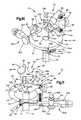
- FIG. 1is a schematic view of an apparatus embodying the present invention
- FIG. 2is a schematic view taken along line 2 — 2 in FIG. 1;
- FIG. 3is a schematic view taken along line 3 — 3 in FIG. 1 showing part of the apparatus of FIG. 1;
- FIG. 4is a schematic view taken along line 4 — 4 in FIG. 1 showing part of the apparatus of FIG. 1;
- FIG. 5is a schematic view taken along line 5 — 5 in FIG. 1 with parts removed;
- FIG. 6is a schematic view taken along line 6 — 6 in FIG. 1;
- FIG. 7is a schematic view taken along line 7 — 7 in FIG. 1 showing part of the apparatus of FIG. 1;
- FIG. 8is a schematic view taken along line 8 — 8 in FIG. 1 showing part of the apparatus of FIG. 1;
- FIG. 9is a perspective view of the apparatus of FIG. 1;
- FIG. 10is a perspective view of the apparatus of FIG. 1 looking at the apparatus from an angle different than FIG. 9;
- FIG. 11is a perspective view of the apparatus of FIG. 1 looking at the apparatus from an angle different than FIGS. 9 and 10;
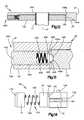
- FIG. 12is a sectional view taken approximately along line 12 — 12 of FIG. 4;
- FIG. 13is an enlarged view of a part of FIG. 12;
- FIG. 14is a schematic view taken along line 14 — 14 in FIG. 5 with parts removed;
- FIG. 15is a view further illustrating parts shown in FIG. 5;
- FIG. 16is a view taken approximately along line 16 — 16 of FIG. 15;
- FIG. 17is a schematic view showing the apparatus of the present invention with an associated known mechanical arm.
- FIG. 18is a schematic view of another feature of part of the apparatus of FIG. 1 .
- the Figuresillustrate an apparatus 10 for use in percutaneous surgery including a cannula 11 , a first support 20 , a second support 40 , a first adjustment mechanism 60 , a second adjustment mechanism 80 , and a third adjustment mechanism 100 .
- the cannula 11is a cylindrical metal or plastic tube with a channel 12 extending completely through the cannula 11 .
- the channel 12has a central axis 14 .
- the cannulais inserted through an incision into a body of a patient during surgery.
- One end portion of the cannulais expandable in the body of the patient as shown in an advertisement entitled “Endius® Spine Endoscopy System with FlexPosureTM.”
- the cannulais also disclosed in U.S. patent application Ser. No. 09/137,335, Filed Aug. 20, 1998.
- the first support 20is associated with the cannula 11 and has a circular perimeter 21 .
- the perimeter 21has a center 22 located on the central axis 14 .
- the first support 20comprises a circular platform, or disk 24 , which has a circular opening 26 in the central area of the disk 24 for receiving an end portion 16 of the cannula 11 .
- the circular opening 26has a center located on the central axis 14 .
- the end portion 16 of the cannula 11can be easily inserted into and removed from the opening 26 .
- the disk 24has a projection portion 20 a , which is located adjacent the perimeter 21 of the disk 24 .
- the disk 24has an upper circular surface area 24 a , which surrounds the opening 26 .
- the second support 40connects to a viewing device 200 consisting of a camera head 201 and an endoscope 202 with a rod and lens assembly 203 , herein referred to as a viewing element, extending down into the channel 12 of the cannula 11 .
- the second support 40includes a body 42 having an opening 44 through which the viewing device 200 extends and a clamp 46 for clamping the viewing device 200 to the body 42 in the opening 44 .
- the clamp 46includes a threaded set screw 48 for securing the viewing device 200 to the body 42 .
- the set screw 48has a manually rotatable knob 48 a and a stem threaded into the body 42 . When rotated, the screw 48 moves axially relative to the body 42 to clamp or release the viewing device 200 depending on the direction of rotation of the screw 48 .
- the body 42 of the second support 40further includes two extension arms 51 , 52 (FIG. 3) for supporting the endoscope 202 .
- Each extension arm 51 , 52includes a threaded bore for receiving a resilient detent member, or ball plunger 400 .
- a ball plunger 400is illustrated at another location in the apparatus 10 .
- Each ball plunger 400including those in the extension arms 51 , 52 , has an externally threaded tubular body 402 with a cylindrical cavity 404 located therein.
- the cavity 404houses a projection 406 and a coiled spring 408 .
- the projections 406 of the two ball plungers 400 of the extension arms 51 , 52are spherical detent members 420 in the form of balls (not shown).
- the spring 408urges each projection 406 against a lip portion 409 of the body 402 .
- the lip portion 409is located at one end of the cavity 404 .
- the other ball plungers 400 of the apparatus 10have project ions 406 with hemispherical extensions 420 and shoulder portions 422 .
- the endoscope 202has corresponding hemispherical recesses (not shown) for receiving the spherical detent members (balls) of the ball plungers 400 which are located in extension arms 51 , 52 .
- the springs 408will compress in each ball plunger 400 in each extension arm 51 , 52 and the spherical detent members will move inward of each cavity 404 and then spring back into the hemispherical recesses in the endoscope 202 , as the endoscope 202 is inserted between the extension arms 51 , 52 .
- the entire viewing device 200will thus be secured between the extension arms 51 , 52 , but may be removed by overcoming the force of the spherical detent members of each ball plunger 400 in the extension arms 51 , 52 .
- the ball plunger 400further includes a head portion 430 with a slot 432 for engaging a tool, such as a screwdriver.
- the ball plunger 400may be threadedly adjusted within the threaded bore of either extension arm 51 , 52 to alter the distance that the spherical detent member 420 projects away from the extension arms 51 , 52 (toward each other). This distance, along with the stiffness of each spring 408 , will determine the holding force by which the endoscope 202 is secured between the extension arms 51 , 52 .
- the first adjustment mechanism 60provides for relative axial adjustment of the cannula 11 and first support 20 along the central axis 14 .
- the first adjustment mechanism 60includes a first toothed rack member 62 , a cannula gripper mechanism 64 fixedly connected to the first rack member 62 , a first manually adjustable, rotatable knob 66 rotatably carried by the projection portion 20 a of the first support 20 , and a first gear member 65 (FIG. 7) rotatable by the first knob 66 and in meshing engagement with the teeth 63 of the first rack member 62 .
- the first support 20 and, in particular, the projection portion 20 arotatably carries the first gear member 65 (FIG. 7 ).
- the first rack member 62is secured to slide axially within the first support 20 and the projection portion 20 a by two ball plungers 400 (FIG. 7 ).
- One ball plunger 400is tangentially threaded into a tapered, threaded bore (FIG. 2) in the perimeter 21 of the first support 20 and the other is tangentially threaded into a threaded bore in the projection portion 20 a .
- the hemispherical extensions 420thus frictionally engage a smooth portion (without teeth 63 ) of the first rack member 62 and bias the first rack member 62 against the first support 20 and the projection portion 20 a . This biasing also maintains the engagement of the first rack member 62 and the first gear member 65 (FIG. 7 ).
- the cannula gripper mechanism 64includes two gripper arms 72 , 74 for clamping against the outer surface of the cannula 11 , and a gripper actuating lever 76 for moving the arms 72 , 74 into engagement with the outer surface of the cannula 11 and for releasing the arms 72 , 74 from engagement with the cannula 11 .
- the cannula gripper mechanism 64further includes a support pin 177 , a coiled spring 188 , a washer 189 with a bore (not shown), and a lock pin 190 .
- the support pin 177has a head 179 , a shaft 180 , and an oblong, or flat end 181 which can mate with the bore in the washer 189 . This structure could be different.
- the coiled spring 188is interposed between the arms 72 , 74 .
- the flat end 181 of the support pin 177is inserted through a circular bore in the first clamp arm 72 , through the coil of the spring 188 , through a circular bore in the second arm 74 , and through the bore in the washer 189 .
- the flat end 181 of the support pin 177is then inserted into a slot 176 in the lever 76 .
- the lock pin 190is inserted through a bore in the lever 76 and through a bore in the flat end 181 of the support pin 177 thereby securing the mechanism 64 together and allowing the lever 76 to rotate about the lock pin 190 .
- a camming surface 178 on the lever 76 adjacent the washer 189forces the arms 72 , 74 together to grip the cannula 11 as the lever 76 is rotated clockwise (as viewed in FIG. 5 ). Counterclockwise rotation of the lever 76 allows the spring 188 to force the arms 72 , 74 apart and releases the cannula 11 from the gripper mechanism 64 .
- the gripper mechanism 64When the gripper mechanism 64 is either gripping the cannula 11 or released from the cannula 11 and the knob 66 is rotated, the disk 24 and parts attached to the disk 24 will move along the axis 14 of the cannula 11 relative to the cannula 11 .
- the viewing device 200may be positioned on the apparatus 10 and adjusted along the cannula axis 14 by rotation of knob 66 .
- the second adjustment mechanism 80provides axial adjustment of the first and second supports 20 , 40 relative to each other along the central axis 14 .
- the second adjustment mechanism 80includes a second toothed rack member 82 connected to the first support 20 , a second manually adjustable, rotatable knob 86 rotatably carried by the body 42 of the second support 40 , and a second toothed gear member 85 (FIG. 8) rotatable by the second knob 86 and in meshing engagement with the teeth 83 of the second rack member 82 .
- the second support 40and in particular, the body 42 , rotatably carries the second gear member 85 (FIG. 8 ).
- the body 42 of the second support 40may have a notch 49 which can fit around part 102 a of the third adjustment mechanism 100 and allow the lower surface of the body 42 to completely abut the disk 24 as the body 42 is brought into an axial position adjacent the disk 24 .
- the second rack member 82is secured to slide axially within the second support 40 by a ball plunger 400 (FIG. 8 ).
- the ball plunger 400is tangentially threaded into a threaded bore in the side of the notch 49 of the second support 40 .
- the hemispherical extension 420thus frictionally engages a smooth portion (without teeth 83 ) of the second rack member 82 and biases the second rack member 82 against the second support 40 .
- the biasingalso maintains the engagement of the second rack member 82 and the second gear member 85 .
- Both sides of the notch 49have tapered portions 49 a , 49 b for facilitating insertion of the ball plunger 400 into the threaded bore of the notch 49 of the second support 40 .
- Rotation of the knob 86causes the body 42 and the viewing device 200 attached thereto to move relative to the cannula 11 and disk 24 along the central axis 14 .
- the third adjustment mechanism 100provides arcuate, circumferential adjustment of the second support 40 about the central axis 14 relative to the first support 20 .
- the third adjustment mechanism 100includes a wedge-shaped support member 102 (FIG. 4) fixedly connecting the second rack member 82 to a ring member 104 which is rotatably supported by the first support 20 and rotatable about the central axis 14 relative to the first support 20 (FIG. 12 ).
- the third adjustment mechanismfurther includes a third manually adjustable, rotatable knob 106 which is part of a set screw.
- the set screwis rotatably threaded into a projection portion 102 a of the support member 102 and is engageable with the circular perimeter 21 of the disk 24 of the first support 20 to lock the support member 102 in an arcuate position relative to the first support 20 and the central axis 14 .
- the ring member 104is supported within a cylindrical, open ended recess 105 of the first support 20 .
- the recess 105is concentric about the central axis 14 .
- the perimeter 104 a of the ring member 104has a groove 104 b for engaging a plurality of ball plungers 400 (preferably four equally spaced apart) in the first support 20 .
- Each of these ball plungers 400is similar in construction.
- Each ball plunger 400is threaded radially into the perimeter 21 of the first support 20 to provide a hemispherical extension 420 extending into the recess 105 of the first support 20 .
- the ring member 104thus is biasingly supported within the recess 105 of the first support 20 and can rotatably slide within the recess 105 about the central axis 14 .
- the ball plungers 400operatively support the ring member 104 in the recess 105 of the first support 20 .
- the ring member 104along with the second support 40 and the second and third adjustment mechanisms 80 , 100 , can be easily removed from the recess 105 for cleaning, maintenance, etc. of the parts by overcoming the force applied by the ball plungers 400 to the ring member 104 .
- the knob 106is rotated to disengage the perimeter 21 of disk 24 , the body 42 and parts connected thereto can be manually rotated about the central axis 14 . This causes the viewing device 200 to rotate about the axis 14 of the cannula 11 and enables the surgeon to view different parts of the surgical sight as desired.
- the fixed connections of the first rack member 62 to a support arm 300 , the second rack member 82 to the wedge-shaped support member 102 , and the support member 102 to the ring member 104may be made by one or more suitable metal fasteners 290 , such as rivets or bolts.
- the entire apparatus 10can be constructed from metal or any other suitable material having sufficient mechanical strength and durability. Certain parts may be made from materials permitting X-rays and other techniques for viewing the surgical sight (i.e., radiopaque parts). Other parts may also be made from non-magnetic materials to reduce electromagnetic interference (i.e., electromagnetic insulating parts).
- the grippers arms 72 , 74are a part of the support arm 300 for attaching the apparatus 10 to a mechanical robotic arm 301 .
- the support arm 300includes an arm portion 302 which is formed integrally with the arms 72 , 74 .
- the arms 72 , 74are integrally constructed with the arm portion 302 .
- the support arm 300also includes an arm portion 303 .
- the arm portion 303has an attaching structure 304 , including a groove 305 , which snaps into a socket in the mechanical arm 301 .
- Detents of any suitable type and designated 306 in the mechanical arm 301hold the arm portion 303 in position in the socket in the mechanical arm 301 .
- the detents 306may be controlled by external actuation levers (not shown) on the mechanical arm 301 for manually releasing the arm portion 303 from the mechanical arm 301 .
- the arm portions 302 and 303are pivotally connected to each other by a fastener 310 .
- the fastener 310extends through an opening 311 in the arm portion 302 and threads into a threaded opening 312 in the arm portion 303 .
- the arm portions 302 , 303may pivot relative each other about a pivot axis 314 .
- the pivot axis 314is centered on the axis of the fastener 310 and the axis of the threaded opening 312 .
- the arm portions 302 , 303are secured together against pivoting movement.
- the arm portions 303 , 302may pivot relative to each other about the axis 314 .
- the end of the arm portion 302which is adjacent to the arm portion 303 , has a convex surface 350 , which is curved about the axis 314 .
- the arm portion 303has a concave surface 351 , which is also curved about the axis 314 .
- the surfaces 350 , 351move concentrically relative to each other when the arm portions 303 and 302 pivot relatively about the axis 314 .
- the arm portion 303has a set of teeth 320 which encircle the axis 314 and which project axially toward a set of teeth 321 on the arm portion 302 .
- the teeth 321project axially toward the teeth 320 .
- the teeth 320 and the teeth 321mesh with each other and provide a locking action so that the arm portions 302 , 303 are positively locked against relative movement about axis 314 when the fastener 310 is tightly screwed into the opening 312 .
- the teeth 320 , 321comprise a lock which blocks relative rotation of the arm portions 302 , 303 about the axis 314 .
- the arm portions 302 , 303When the fastener 310 is loosened, the arm portions 302 , 303 may be rotated relative to each other about the axis 314 , and thus, the arm portions 302 , 303 may pivot relative to each other to adjust the position of the apparatus 10 .
- a cylindrical projection 325is welded to the arm portion 303 .
- the projection 325 and arm portion 303are fixedly connected together.
- the projection 325is centered on the axis 314 and contains a chamber 328 .
- the chamber 328communicates with a fluid passage 329 in a male fluid connector 331 .
- the male connector 331attaches to a male connector 333 on the mechanical arm 301 by means of a flexible hose 392 so that the fluid passage 329 communicates with a fluid passage in the mechanical arm 301 .
- the chamber 328is closed at its upper end by a cap 335 .
- the cap 335has an opening 336 centered on the axis 314 .
- the opening 336communicates with the chamber 328 .
- a manually movable internal valve member 340normally closes the opening and blocks the chamber 328 from communicating with the ambient air surrounding the support arm 300 .
- the valve member 340is connected to a stem 341 , which is also centered on the axis 314 .
- the stem 341has a knob or button 343 on its end which may be manually depressed to move the stem 341 and valve member 340 downward into the chamber 328 .
- the stem 341 and valve member 340are so moved, the chamber 328 is in communication with the ambient air surrounding the device due to the unblocking of the opening 336 .
- the mechanical arm 301is a known device and is of the type generally disclosed in U.S. Pat. No. 4,863,133.
- the mechanical arm 301is sold by Leonard Medical, Inc. 1464 Holcomb Road, Huntington Valley, Pa., 19006.
- the mechanical arm 301includes relatively movable parts, which permit movement and adjustment of the apparatus 10 in a variety in planes, directions, and orientations.
- the mechanical arm 301permits easy movement when a vacuum is not applied to the arm 301 . When a vacuum is applied to the arm 301 , relative movement of the parts of the arm 301 is resisted, and therefore adjustment of the apparatus 10 is difficult.
- the chamber 328loses its vacuum and the pressure in the chamber 328 increases toward ambient pressure.
- the passage 329communicates this pressure increase to the mechanical arm 301 , and thus the parts of the mechanical arm 301 are free to move and allow for adjustment of the position of the apparatus 10 by the surgeon.
- the support arm 300is snapped into the socket of the mechanical arm 301 where it is held by the detent 306 .
- the surgeonmay then depress the button 343 and relatively move parts of the mechanical arm 301 as well as the apparatus 10 into the position where the surgeon desires the apparatus 10 to be.
- This positionmay be where the opening 26 in the disk 24 is aligned with the end portion 16 of the cannula 11 with the opposite end portion of the cannula 11 being located in an incision in the body of a patient.
- the viewing device 200may be mounted on the apparatus 10 , and the surgeon may make adjustments prior to and during the surgical procedure as desired, as described above.
- the apparatus 10may include a second support 40 with a fourth adjustment mechanism 500 for rotating the viewing device 200 about an axis 501 (FIG. 10) defined by the ball plungers 400 of the extension arms 51 , 52 when set screw 48 is not clamping the viewing device 200 to the body 42 .
- the axis 501is offset from the axis 14 of the cannula 11 and perpendicular to the axis 14 of the cannula 11 .
- Rotation of the viewing device 200 about axis 501causes the endoscope 202 and the rod and lens assembly 203 to move perpendicular to the central axis 14 of the cannula 11 . This rotation will result in radial adjustment of the position of the rod and lens assembly 203 in a radial direction transverse to the central axis 14 .
- the spring-loaded connections of the spherical detent members 420 of the ball plungers 400 and the hemispherical recesses of the endoscope 202allow rotation about the axis 501 when the set screw 48 is released from clamping engagement of the viewing device 200 .
- the mechanism 500includes a threaded bore 510 in the second support 40 and an adjustable member 520 for moving (vertically as viewed in the FIGS.) a part of the viewing device 200 about the axis 501 .
- the adjustable member 520has a rounded first end portion 522 , a threaded middle portion 524 , and a knurled second end portion 526 , or knob.
- the bore 510extends at an angle as shown in FIG. 18 from a lower portion of the second support 40 up to the opening 44 in the clamp 46 of the second support 40 .
- the adjustable member 520is rotated and threaded into the bore 510 and may be rotated until the first end portion 522 protrudes into the opening 44 of the second support 40 . Accordingly, when the surgeon wishes to adjust the rod and lens assembly 203 (within the surgical sight) about the axis 501 and radially relative to the axis 14 of the cannula 11 , the surgeon may loosen the connection of the set screw 48 with the viewing device 200 and rotate the adjustable member 520 by manually rotating knob 526 so that the first end portion 522 vertically extends farther or less into the opening 44 .
- This adjustmentwill adjust the part of the viewing device 200 engaged by the clamp 46 along the central axis 14 , rotate the viewing device 200 about the axis 501 , and cause the lens 203 at the surgical sight to move transverse to the axis 14 of the cannula 11 . This will expand the area of the surgical sight which the surgeon may view.
- the surgeonmay tighten the set screw 48 and re-secure the viewing device 200 to the second support 40 of the apparatus 10 .
Landscapes
- Health & Medical Sciences (AREA)
- Life Sciences & Earth Sciences (AREA)
- Surgery (AREA)
- General Health & Medical Sciences (AREA)
- Public Health (AREA)
- Veterinary Medicine (AREA)
- Pathology (AREA)
- Nuclear Medicine, Radiotherapy & Molecular Imaging (AREA)
- Animal Behavior & Ethology (AREA)
- Engineering & Computer Science (AREA)
- Biomedical Technology (AREA)
- Heart & Thoracic Surgery (AREA)
- Medical Informatics (AREA)
- Molecular Biology (AREA)
- Biophysics (AREA)
- Physics & Mathematics (AREA)
- Radiology & Medical Imaging (AREA)
- Optics & Photonics (AREA)
- Oral & Maxillofacial Surgery (AREA)
- Surgical Instruments (AREA)
- Endoscopes (AREA)
Abstract
Description
Claims (42)
Priority Applications (5)
| Application Number | Priority Date | Filing Date | Title |
|---|---|---|---|
| US09/491,808US6361488B1 (en) | 2000-01-28 | 2000-01-28 | Support apparatus for endoscopic surgery |
| EP01903320AEP1251767A4 (en) | 2000-01-28 | 2001-01-24 | Support apparatus for endoscopic surgery |
| JP2001555541AJP2003521295A (en) | 2000-01-28 | 2001-01-24 | Support device for endoscopic surgery |
| PCT/US2001/002499WO2001054560A2 (en) | 2000-01-28 | 2001-01-24 | Support apparatus for endoscopic surgery |
| AU2001231152AAU2001231152A1 (en) | 2000-01-28 | 2001-01-24 | Support apparatus for endoscopic surgery |
Applications Claiming Priority (1)
| Application Number | Priority Date | Filing Date | Title |
|---|---|---|---|
| US09/491,808US6361488B1 (en) | 2000-01-28 | 2000-01-28 | Support apparatus for endoscopic surgery |
Publications (1)
| Publication Number | Publication Date |
|---|---|
| US6361488B1true US6361488B1 (en) | 2002-03-26 |
Family
ID=23953760
Family Applications (1)
| Application Number | Title | Priority Date | Filing Date |
|---|---|---|---|
| US09/491,808Expired - LifetimeUS6361488B1 (en) | 2000-01-28 | 2000-01-28 | Support apparatus for endoscopic surgery |
Country Status (5)
| Country | Link |
|---|---|
| US (1) | US6361488B1 (en) |
| EP (1) | EP1251767A4 (en) |
| JP (1) | JP2003521295A (en) |
| AU (1) | AU2001231152A1 (en) |
| WO (1) | WO2001054560A2 (en) |
Cited By (50)
| Publication number | Priority date | Publication date | Assignee | Title |
|---|---|---|---|---|
| US20020177752A1 (en)* | 2001-05-24 | 2002-11-28 | Minnesota Scientific, Inc. | Cam-wedge locking mechanism |
| US20030040656A1 (en)* | 2001-08-27 | 2003-02-27 | Endius Incorporated | Apparatus for adjustably supporting an endoscope |
| WO2002078767A3 (en)* | 2001-03-29 | 2003-02-27 | Endius Inc | Apparatus for adjustably supporting an endoscope |
| US6530880B2 (en)* | 2001-03-29 | 2003-03-11 | Endius Incorporated | Apparatus for supporting an endoscope |
| US20030073998A1 (en)* | 2000-08-01 | 2003-04-17 | Endius Incorporated | Method of securing vertebrae |
| US20030153927A1 (en)* | 2001-05-15 | 2003-08-14 | Endius Incorporated | Structure for receiving surgical instruments |
| US20030191372A1 (en)* | 2001-05-24 | 2003-10-09 | Minnesota Scientific, Inc. | Cam-wedge locking mechanism |
| US20030195551A1 (en)* | 1998-08-20 | 2003-10-16 | Davison Thomas W. | Cannula for receiving surgical instruments |
| US6663616B1 (en)* | 1997-02-24 | 2003-12-16 | Co.Don Aktiengesellschaft | Set of surgical instruments |
| US20030236529A1 (en)* | 2002-06-24 | 2003-12-25 | Endius Incorporated | Surgical instrument for moving vertebrae |
| US6679833B2 (en)* | 1996-03-22 | 2004-01-20 | Sdgi Holdings, Inc. | Devices and methods for percutaneous surgery |
| US20040024387A1 (en)* | 2002-04-15 | 2004-02-05 | Shaharam Payandeh | Devices for positioning implements about fixed points |
| US20040133201A1 (en)* | 2000-08-01 | 2004-07-08 | Alan Shluzas | Methods and apparatuses for treating the spine through an access device |
| US20040148369A1 (en)* | 2002-07-11 | 2004-07-29 | John Strassner | Repository-independent system and method for asset management and reconciliation |
| US20040176763A1 (en)* | 1996-03-22 | 2004-09-09 | Foley Kevin T. | Methods for percutaneous surgery |
| US20040186346A1 (en)* | 1996-03-22 | 2004-09-23 | Smith Maurice M. | Devices and methods for percutaneous surgery |
| US20040230100A1 (en)* | 2003-05-16 | 2004-11-18 | Shluzas Alan E. | Access device for minimally invasive surgery |
| US20050075540A1 (en)* | 2003-08-26 | 2005-04-07 | Shluzas Alan E. | Minimally invasive access device and method |
| US20050075644A1 (en)* | 2003-10-02 | 2005-04-07 | Dipoto Gene | Methods and apparatuses for minimally invasive replacement of intervertebral discs |
| US20050090899A1 (en)* | 2003-10-24 | 2005-04-28 | Dipoto Gene | Methods and apparatuses for treating the spine through an access device |
| US20050090822A1 (en)* | 2003-10-24 | 2005-04-28 | Dipoto Gene | Methods and apparatus for stabilizing the spine through an access device |
| US20050090833A1 (en)* | 2003-10-24 | 2005-04-28 | Dipoto Gene | Methods and apparatuses for fixation of the spine through an access device |
| US20050251192A1 (en)* | 2004-03-31 | 2005-11-10 | Shluzas Alan E | Access device having discrete visualization locations |
| EP1582138A3 (en)* | 2004-04-02 | 2005-12-07 | Olympus Corporation | Medical system with over-tube |
| US20050273132A1 (en)* | 2003-08-26 | 2005-12-08 | Shluzas Alan E | Access systems and methods for minimally invasive surgery |
| US20060052812A1 (en)* | 2004-09-07 | 2006-03-09 | Michael Winer | Tool for preparing a surgical site for an access device |
| WO2006045089A2 (en) | 2004-10-20 | 2006-04-27 | Endius Incorporated | An apparatus for connecting a longitudinal member to a bone portion |
| US20060089652A1 (en)* | 2004-10-26 | 2006-04-27 | Concept Matrix, Llc | Working channel for minimally invasive spine surgery |
| US20060089662A1 (en)* | 1998-08-20 | 2006-04-27 | Davison Thomas W | Method and apparatus for securing vertebrae |
| US20060195017A1 (en)* | 2004-11-22 | 2006-08-31 | Shluzas Alan E | Expandable device for providing access to the spine |
| US20070016223A1 (en)* | 2002-10-25 | 2007-01-18 | Pagliuca James J | Apparatus and methods for shielding body structures during surgery |
| US20070233089A1 (en)* | 2006-02-17 | 2007-10-04 | Endius, Inc. | Systems and methods for reducing adjacent level disc disease |
| US20070238932A1 (en)* | 2006-03-08 | 2007-10-11 | Jones Robert J | Surgical retractor and retractor assembly |
| US20070288026A1 (en)* | 2006-06-09 | 2007-12-13 | Endius, Inc. | Methods and apparatus for access to and/or treatment of the spine |
| US20080077143A1 (en)* | 2006-09-25 | 2008-03-27 | Zimmer Spine, Inc. | Apparatus for connecting a longitudinal member to a bone portion |
| US7618444B2 (en) | 2002-09-06 | 2009-11-17 | Zimmer Spine, Inc. | Surgical instrument for moving a vertebra |
| US20090326555A1 (en)* | 2008-06-30 | 2009-12-31 | Eigen, Inc. | Support assembly for a tracking assembly and mounted transrectal ultrasound probe |
| US7641670B2 (en) | 1998-08-20 | 2010-01-05 | Zimmer Spine, Inc. | Cannula for receiving surgical instruments |
| US7651496B2 (en) | 2004-07-23 | 2010-01-26 | Zimmer Spine, Inc. | Methods and apparatuses for percutaneous implant delivery |
| US7658739B2 (en) | 2005-09-27 | 2010-02-09 | Zimmer Spine, Inc. | Methods and apparatuses for stabilizing the spine through an access device |
| US20110087257A1 (en)* | 2009-04-02 | 2011-04-14 | Spine View, Inc. | Minimally invasive discectomy |
| USRE44268E1 (en) | 1997-07-15 | 2013-06-04 | Zimmer Spine, Inc. | Method and instruments for percutaneous arthroscopic disc removal, bone biopsy and fixation of the vertebral |
| US9788856B2 (en) | 2014-03-11 | 2017-10-17 | Stryker European Holdings I, Llc | Endoscopic surgical systems and methods |
| US20180161024A1 (en)* | 2016-08-17 | 2018-06-14 | Rebound Therapeutics Corporation | Cannula with proximally mounted camera |
| US10172525B2 (en) | 2015-08-17 | 2019-01-08 | Rebound Therapeutics Corporation | Cannula with proximally mounted camera |
| KR20190032610A (en)* | 2016-08-17 | 2019-03-27 | 리바운드 세라퓨틱스 코포레이션 | The cannula in which the camera is installed close- |
| JP2019528822A (en)* | 2016-08-17 | 2019-10-17 | リバウンド セラピュティクス コーポレーションRebound Therapeutics Corporation | Cannula with camera attached proximally |
| US20200179078A1 (en)* | 2018-12-06 | 2020-06-11 | Rebound Therapeutics Corporation | Cannula and Proximally Mounted Camera with an Imaging Control System for Rotating Images |
| CN112336390A (en)* | 2019-08-07 | 2021-02-09 | 卡尔史托斯股份有限公司 | Device for simultaneously securing medical instruments and corresponding system |
| CN112349191A (en)* | 2020-10-14 | 2021-02-09 | 北京众绘虚拟现实技术研究院有限公司 | Parallel force feedback mechanism for laparoscopic surgery simulation |
Families Citing this family (3)
| Publication number | Priority date | Publication date | Assignee | Title |
|---|---|---|---|---|
| US7682370B2 (en) | 1998-08-20 | 2010-03-23 | Zimmer Spine, Inc. | Surgical tool for use in expanding a cannula |
| US7395563B2 (en)* | 2004-04-02 | 2008-07-08 | Civco Medical Instruments Co., Inc. | Support system for use when performing medical imaging of a patient |
| JP2008017903A (en)* | 2006-07-11 | 2008-01-31 | Gifu Univ | Endoscope holding device |
Citations (5)
| Publication number | Priority date | Publication date | Assignee | Title |
|---|---|---|---|---|
| US5520607A (en)* | 1994-03-04 | 1996-05-28 | Vision Sciences, Inc. | Holding tray and clamp assembly for an endoscopic sheath |
| US5571072A (en)* | 1995-04-28 | 1996-11-05 | Kronner; Richard F. | Dual-axis endoscope holder |
| US5792044A (en)* | 1996-03-22 | 1998-08-11 | Danek Medical, Inc. | Devices and methods for percutaneous surgery |
| US6152871A (en) | 1996-03-22 | 2000-11-28 | Sdgi Holdings, Inc. | Apparatus for percutaneous surgery |
| US6162170A (en) | 1996-03-22 | 2000-12-19 | Sdgi Holdings, Inc. | Devices and methods for percutaneous surgery |
Family Cites Families (3)
| Publication number | Priority date | Publication date | Assignee | Title |
|---|---|---|---|---|
| JP3244645B2 (en)* | 1997-05-07 | 2002-01-07 | 旭光学工業株式会社 | Endoscopic surgical treatment instrument |
| JP3429685B2 (en)* | 1997-10-06 | 2003-07-22 | オリンパス光学工業株式会社 | Endoscope guide tube |
| DE29916026U1 (en)* | 1999-09-11 | 1999-11-18 | Aesculap AG & Co. KG, 78532 Tuttlingen | Holding device for a surgical instrument |
- 2000
- 2000-01-28USUS09/491,808patent/US6361488B1/ennot_activeExpired - Lifetime
- 2001
- 2001-01-24AUAU2001231152Apatent/AU2001231152A1/ennot_activeAbandoned
- 2001-01-24JPJP2001555541Apatent/JP2003521295A/enactivePending
- 2001-01-24EPEP01903320Apatent/EP1251767A4/ennot_activeWithdrawn
- 2001-01-24WOPCT/US2001/002499patent/WO2001054560A2/enactiveApplication Filing
Patent Citations (10)
| Publication number | Priority date | Publication date | Assignee | Title |
|---|---|---|---|---|
| US5520607A (en)* | 1994-03-04 | 1996-05-28 | Vision Sciences, Inc. | Holding tray and clamp assembly for an endoscopic sheath |
| US5571072A (en)* | 1995-04-28 | 1996-11-05 | Kronner; Richard F. | Dual-axis endoscope holder |
| US5792044A (en)* | 1996-03-22 | 1998-08-11 | Danek Medical, Inc. | Devices and methods for percutaneous surgery |
| US5954635A (en) | 1996-03-22 | 1999-09-21 | Sdgi Holdings Inc. | Devices and methods for percutaneous surgery |
| US6007487A (en) | 1996-03-22 | 1999-12-28 | Sdgi Holdings, Inc. | Tissue retractor for use through a cannula |
| US6152871A (en) | 1996-03-22 | 2000-11-28 | Sdgi Holdings, Inc. | Apparatus for percutaneous surgery |
| US6162170A (en) | 1996-03-22 | 2000-12-19 | Sdgi Holdings, Inc. | Devices and methods for percutaneous surgery |
| US6176823B1 (en) | 1996-03-22 | 2001-01-23 | Sdgi Holdings, Inc. | Fixture for supporting a viewing element within a cannula |
| US6206822B1 (en) | 1996-03-22 | 2001-03-27 | Sdgi Holdings, Inc. | Devices and methods for percutaneous surgery |
| US6217509B1 (en) | 1996-03-22 | 2001-04-17 | Sdgi Holdings, Inc. | Devices and methods for percutaneous surgery |
Cited By (164)
| Publication number | Priority date | Publication date | Assignee | Title |
|---|---|---|---|---|
| US20040186346A1 (en)* | 1996-03-22 | 2004-09-23 | Smith Maurice M. | Devices and methods for percutaneous surgery |
| US20040176763A1 (en)* | 1996-03-22 | 2004-09-09 | Foley Kevin T. | Methods for percutaneous surgery |
| US6679833B2 (en)* | 1996-03-22 | 2004-01-20 | Sdgi Holdings, Inc. | Devices and methods for percutaneous surgery |
| US7198598B2 (en) | 1996-03-22 | 2007-04-03 | Warsaw Orthopedic, Inc. | Devices and methods for percutaneous surgery |
| US6663616B1 (en)* | 1997-02-24 | 2003-12-16 | Co.Don Aktiengesellschaft | Set of surgical instruments |
| USRE44268E1 (en) | 1997-07-15 | 2013-06-04 | Zimmer Spine, Inc. | Method and instruments for percutaneous arthroscopic disc removal, bone biopsy and fixation of the vertebral |
| US20030195551A1 (en)* | 1998-08-20 | 2003-10-16 | Davison Thomas W. | Cannula for receiving surgical instruments |
| US7641670B2 (en) | 1998-08-20 | 2010-01-05 | Zimmer Spine, Inc. | Cannula for receiving surgical instruments |
| US8968351B2 (en) | 1998-08-20 | 2015-03-03 | Zimmer Spine, Inc. | Cannula for receiving surgical instruments |
| US20030195550A1 (en)* | 1998-08-20 | 2003-10-16 | Davison Thomas W. | Cannula for receiving surgical instruments |
| US20030195549A1 (en)* | 1998-08-20 | 2003-10-16 | Davison Thomas W. | Cannula for receiving surgical instruments |
| US20030199885A1 (en)* | 1998-08-20 | 2003-10-23 | Davison Thomas W. | Cannula for receiving surgical instruments |
| US20030199884A1 (en)* | 1998-08-20 | 2003-10-23 | Endius Incorporated | Method for performing a surgical procedure and a cannula for use in performing the surgical procedure |
| US7892171B2 (en) | 1998-08-20 | 2011-02-22 | Zimmer Spine, Inc. | Cannula for receiving surgical instruments |
| US20060276822A1 (en)* | 1998-08-20 | 2006-12-07 | Davison Thomas W | Cannula for receiving surgical instruments |
| US7223278B2 (en) | 1998-08-20 | 2007-05-29 | Endius, Inc. | Cannula for receiving surgical instruments |
| US7892249B2 (en) | 1998-08-20 | 2011-02-22 | Zimmer Spine, Inc. | Cannula for receiving surgical instruments |
| US20060264999A1 (en)* | 1998-08-20 | 2006-11-23 | Davison Thomas W | Cannula for receiving surgical instruments |
| US20040093002A1 (en)* | 1998-08-20 | 2004-05-13 | Davison Thomas W. | Cannula for receiving surgical instruments |
| US7108705B2 (en) | 1998-08-20 | 2006-09-19 | Endius, Inc. | Cannula for receiving surgical instruments |
| US20040098012A1 (en)* | 1998-08-20 | 2004-05-20 | Davison Thomas W. | Cannula for receiving surgical instruments |
| US20060276821A1 (en)* | 1998-08-20 | 2006-12-07 | Davison Thomas W | Cannula for receiving surgical instruments |
| US7985237B2 (en) | 1998-08-20 | 2011-07-26 | Zimmer Spine, Inc. | Cannula for receiving surgical instruments |
| US7799036B2 (en) | 1998-08-20 | 2010-09-21 | Zimmer Spine, Inc. | Method and apparatus for securing vertebrae |
| US7674273B2 (en) | 1998-08-20 | 2010-03-09 | Zimmer Spine, Inc. | Method for performing a surgical procedure and a cannula for use in performing the surgical procedure |
| US6800084B2 (en) | 1998-08-20 | 2004-10-05 | Endius Incorporated | Method for performing a surgical procedure and a cannula for use in performing the surgical procedure |
| US20060089662A1 (en)* | 1998-08-20 | 2006-04-27 | Davison Thomas W | Method and apparatus for securing vertebrae |
| US6811558B2 (en) | 1998-08-20 | 2004-11-02 | Endius Incorporated | Method for performing a surgical procedure and a cannula for use in performing the surgical procedure |
| US7033369B2 (en) | 1998-08-20 | 2006-04-25 | Endius, Inc. | Cannula for receiving surgical instruments |
| US7001397B2 (en) | 1998-08-20 | 2006-02-21 | Endius Incorporated | Cannula for receiving surgical instruments |
| US8317817B2 (en) | 1998-08-20 | 2012-11-27 | Zimmer Spine, Inc. | Cannula for receiving surgical instruments |
| US6837891B2 (en) | 1998-08-20 | 2005-01-04 | Endius Incorporated | Cannula for receiving surgical instruments |
| US7670354B2 (en) | 1998-08-20 | 2010-03-02 | Zimmer Spine, Inc. | Cannula for receiving surgical instruments |
| US8540746B2 (en) | 1998-08-20 | 2013-09-24 | Zimmer Spine, Inc. | Cannula for receiving surgical instruments |
| US20050043754A1 (en)* | 1998-08-20 | 2005-02-24 | Davison Thomas W. | Method for performing a surgical procedure and a cannula for use in performing the surgical procedure |
| US20040133201A1 (en)* | 2000-08-01 | 2004-07-08 | Alan Shluzas | Methods and apparatuses for treating the spine through an access device |
| US9622735B2 (en) | 2000-08-01 | 2017-04-18 | Zimmer Spine, Inc. | Method for securing vertebrae |
| US8864785B2 (en) | 2000-08-01 | 2014-10-21 | Zimmer Spine, Inc. | Method for securing vertebrae |
| US7850695B2 (en) | 2000-08-01 | 2010-12-14 | Zimmer Spine, Inc. | Method of securing vertebrae |
| US8777997B2 (en) | 2000-08-01 | 2014-07-15 | Zimmer Spine, Inc. | Method for securing vertebrae |
| US20050033297A1 (en)* | 2000-08-01 | 2005-02-10 | Davison Thomas W. | Method of securing vertebrae |
| US20050021030A1 (en)* | 2000-08-01 | 2005-01-27 | Endius Incorporated | Method of securing vertebrae |
| US20050113833A1 (en)* | 2000-08-01 | 2005-05-26 | Davison Thomas W. | Method of securing vertebrae |
| US20030073998A1 (en)* | 2000-08-01 | 2003-04-17 | Endius Incorporated | Method of securing vertebrae |
| US20040082960A1 (en)* | 2000-08-01 | 2004-04-29 | Davison Thomas W. | Method of securing vertebrae |
| US20040236317A1 (en)* | 2000-08-01 | 2004-11-25 | Davison Thomas W. | Method of securing vertebrae |
| US8277486B2 (en) | 2000-08-01 | 2012-10-02 | Zimmer Spine, Inc. | System for performing a procedure at a spinal location |
| US7722530B2 (en) | 2000-08-01 | 2010-05-25 | Zimmer Spine, Inc. | Method of securing vertebrae |
| US7056321B2 (en) | 2000-08-01 | 2006-06-06 | Endius, Incorporated | Method of securing vertebrae |
| US7699877B2 (en) | 2000-08-01 | 2010-04-20 | Zimmer Spine, Inc. | Method of securing vertebrae |
| US7985247B2 (en) | 2000-08-01 | 2011-07-26 | Zimmer Spine, Inc. | Methods and apparatuses for treating the spine through an access device |
| US9101353B2 (en) | 2000-08-01 | 2015-08-11 | Zimmer Spine, Inc. | Method of securing vertebrae |
| WO2002078767A3 (en)* | 2001-03-29 | 2003-02-27 | Endius Inc | Apparatus for adjustably supporting an endoscope |
| US6530880B2 (en)* | 2001-03-29 | 2003-03-11 | Endius Incorporated | Apparatus for supporting an endoscope |
| US7144393B2 (en) | 2001-05-15 | 2006-12-05 | Dipoto Gene P | Structure for receiving surgical instruments |
| US20070142857A1 (en)* | 2001-05-15 | 2007-06-21 | Dipoto Gene P | Structure for receiving surgical instruments |
| US7985218B2 (en) | 2001-05-15 | 2011-07-26 | Zimmer Spine, Inc. | Structure for receiving surgical instruments |
| US20050149106A1 (en)* | 2001-05-15 | 2005-07-07 | Dipoto Gene P. | Cannula for receiving surgical instruments |
| US20030153927A1 (en)* | 2001-05-15 | 2003-08-14 | Endius Incorporated | Structure for receiving surgical instruments |
| US8007492B2 (en) | 2001-05-15 | 2011-08-30 | Zimmer Spine, Inc. | Cannula for receiving surgical instruments |
| US20040097907A1 (en)* | 2001-05-15 | 2004-05-20 | Dipoto Gene P. | Cannula for receiving surgical instruments |
| US7766930B2 (en) | 2001-05-15 | 2010-08-03 | Zimmer Spine, Inc. | Cannula for receiving surgical instruments |
| US6974412B2 (en) | 2001-05-24 | 2005-12-13 | Minnesota Scientific, Inc. | Cam-wedge locking mechanism |
| US20030191372A1 (en)* | 2001-05-24 | 2003-10-09 | Minnesota Scientific, Inc. | Cam-wedge locking mechanism |
| US20020177752A1 (en)* | 2001-05-24 | 2002-11-28 | Minnesota Scientific, Inc. | Cam-wedge locking mechanism |
| US6572540B2 (en)* | 2001-05-24 | 2003-06-03 | Minnesota Scientific, Inc. | Cam-wedge locking mechanism |
| US20030040656A1 (en)* | 2001-08-27 | 2003-02-27 | Endius Incorporated | Apparatus for adjustably supporting an endoscope |
| US7431693B2 (en) | 2001-08-27 | 2008-10-07 | Zimmer Spine, Inc. | Method for adjustably supporting an endoscope |
| US20050085689A1 (en)* | 2001-08-27 | 2005-04-21 | Endius Incorporated | Apparatus for adjustably supporting an endoscope |
| US6821243B2 (en)* | 2001-08-27 | 2004-11-23 | Endius Incorporated | Apparatus for adjustably supporting an endoscope |
| US20040024387A1 (en)* | 2002-04-15 | 2004-02-05 | Shaharam Payandeh | Devices for positioning implements about fixed points |
| US6997866B2 (en)* | 2002-04-15 | 2006-02-14 | Simon Fraser University | Devices for positioning implements about fixed points |
| US7815650B2 (en) | 2002-06-24 | 2010-10-19 | Zimmer Spine, Inc. | Surgical instrument for moving vertebrae |
| US20030236529A1 (en)* | 2002-06-24 | 2003-12-25 | Endius Incorporated | Surgical instrument for moving vertebrae |
| US7713274B2 (en) | 2002-06-24 | 2010-05-11 | Zimmer Spine, Inc. | Surgical instrument for moving vertebrae |
| US20040199170A1 (en)* | 2002-06-24 | 2004-10-07 | Endius Incorporated | Surgical instrument for moving vertebrae |
| US7341594B2 (en) | 2002-06-24 | 2008-03-11 | Endius Incorporated | Surgical instrument for moving vertebrae |
| US7988700B2 (en) | 2002-06-24 | 2011-08-02 | Zimmer Spine, Inc. | Surgical instrument for moving vertebrae |
| US7004947B2 (en) | 2002-06-24 | 2006-02-28 | Endius Incorporated | Surgical instrument for moving vertebrae |
| US20050159757A1 (en)* | 2002-06-24 | 2005-07-21 | Endius Incorporated | Surgical instrument for moving vertebrae |
| US20040148369A1 (en)* | 2002-07-11 | 2004-07-29 | John Strassner | Repository-independent system and method for asset management and reconciliation |
| US7618444B2 (en) | 2002-09-06 | 2009-11-17 | Zimmer Spine, Inc. | Surgical instrument for moving a vertebra |
| US20070016223A1 (en)* | 2002-10-25 | 2007-01-18 | Pagliuca James J | Apparatus and methods for shielding body structures during surgery |
| US7988623B2 (en) | 2002-10-25 | 2011-08-02 | Zimmer Spine, Inc. | Apparatus and methods for shielding body structures during surgery |
| US20090143829A1 (en)* | 2003-05-16 | 2009-06-04 | Zimmer Spine, Inc. | Access device for minimally invasive surgery |
| US20040230100A1 (en)* | 2003-05-16 | 2004-11-18 | Shluzas Alan E. | Access device for minimally invasive surgery |
| US7645232B2 (en) | 2003-05-16 | 2010-01-12 | Zimmer Spine, Inc. | Access device for minimally invasive surgery |
| US8608651B2 (en) | 2003-05-16 | 2013-12-17 | Zimmer Spine, Inc. | Access device for minimally invasive surgery |
| US7226451B2 (en) | 2003-08-26 | 2007-06-05 | Shluzas Alan E | Minimally invasive access device and method |
| US20050075540A1 (en)* | 2003-08-26 | 2005-04-07 | Shluzas Alan E. | Minimally invasive access device and method |
| US20050273132A1 (en)* | 2003-08-26 | 2005-12-08 | Shluzas Alan E | Access systems and methods for minimally invasive surgery |
| US20050273131A1 (en)* | 2003-08-26 | 2005-12-08 | Shluzas Alan E | Access systems and methods for minimally invasive surgery |
| US7691120B2 (en) | 2003-08-26 | 2010-04-06 | Zimmer Spine, Inc. | Access systems and methods for minimally invasive surgery |
| US7976464B2 (en) | 2003-08-26 | 2011-07-12 | Zimmer Spine, Inc. | Access systems and methods for minimally invasive surgery |
| EP2305127A1 (en) | 2003-08-26 | 2011-04-06 | Endius Incorporated | Adjustable height access device for treating the spine of a patient |
| US20060271057A1 (en)* | 2003-08-26 | 2006-11-30 | Shluzas Alan E | Minimally invasive access device and method |
| WO2005023123A1 (en) | 2003-09-09 | 2005-03-17 | Endius, Inc. | Apparatuses and methods for treating the spine through an access device |
| US20050075644A1 (en)* | 2003-10-02 | 2005-04-07 | Dipoto Gene | Methods and apparatuses for minimally invasive replacement of intervertebral discs |
| US7655012B2 (en) | 2003-10-02 | 2010-02-02 | Zimmer Spine, Inc. | Methods and apparatuses for minimally invasive replacement of intervertebral discs |
| US20050090899A1 (en)* | 2003-10-24 | 2005-04-28 | Dipoto Gene | Methods and apparatuses for treating the spine through an access device |
| US20050090822A1 (en)* | 2003-10-24 | 2005-04-28 | Dipoto Gene | Methods and apparatus for stabilizing the spine through an access device |
| US20050090833A1 (en)* | 2003-10-24 | 2005-04-28 | Dipoto Gene | Methods and apparatuses for fixation of the spine through an access device |
| US7731737B2 (en) | 2003-10-24 | 2010-06-08 | Zimmer Spine, Inc. | Methods and apparatuses for fixation of the spine through an access device |
| US20050251192A1 (en)* | 2004-03-31 | 2005-11-10 | Shluzas Alan E | Access device having discrete visualization locations |
| EP1582138A3 (en)* | 2004-04-02 | 2005-12-07 | Olympus Corporation | Medical system with over-tube |
| US7651496B2 (en) | 2004-07-23 | 2010-01-26 | Zimmer Spine, Inc. | Methods and apparatuses for percutaneous implant delivery |
| US20070299444A1 (en)* | 2004-08-26 | 2007-12-27 | Endius, Inc. | Methods and apparatus for access to and/or treatment of the spine |
| US9055934B2 (en) | 2004-08-26 | 2015-06-16 | Zimmer Spine, Inc. | Methods and apparatus for access to and/or treatment of the spine |
| US20060052812A1 (en)* | 2004-09-07 | 2006-03-09 | Michael Winer | Tool for preparing a surgical site for an access device |
| WO2006045089A2 (en) | 2004-10-20 | 2006-04-27 | Endius Incorporated | An apparatus for connecting a longitudinal member to a bone portion |
| US20060089652A1 (en)* | 2004-10-26 | 2006-04-27 | Concept Matrix, Llc | Working channel for minimally invasive spine surgery |
| US8206292B2 (en) | 2004-10-26 | 2012-06-26 | Concept Matrix, Llc | Working channel for minimally invasive spine surgery |
| US7651499B2 (en) | 2004-10-26 | 2010-01-26 | Concept Matrix, Llc | Working channel for minimally invasive spine surgery |
| US20060195017A1 (en)* | 2004-11-22 | 2006-08-31 | Shluzas Alan E | Expandable device for providing access to the spine |
| US8167911B2 (en) | 2005-07-20 | 2012-05-01 | Zimmer Spine, Inc. | Apparatus for connecting a longitudinal member to a bone portion |
| US20070021750A1 (en)* | 2005-07-20 | 2007-01-25 | Shluzas Alan E | Apparatus for connecting a longitudinal member to a bone portion |
| US8016828B2 (en) | 2005-09-27 | 2011-09-13 | Zimmer Spine, Inc. | Methods and apparatuses for stabilizing the spine through an access device |
| US7658739B2 (en) | 2005-09-27 | 2010-02-09 | Zimmer Spine, Inc. | Methods and apparatuses for stabilizing the spine through an access device |
| US20100069961A1 (en)* | 2006-02-17 | 2010-03-18 | Zimmer Spine, Inc. | Systems and methods for reducing adjacent level disc disease |
| US20070233089A1 (en)* | 2006-02-17 | 2007-10-04 | Endius, Inc. | Systems and methods for reducing adjacent level disc disease |
| US8876687B2 (en) | 2006-03-08 | 2014-11-04 | Zimmer Spine, Inc. | Surgical retractor and retractor assembly |
| US20070238932A1 (en)* | 2006-03-08 | 2007-10-11 | Jones Robert J | Surgical retractor and retractor assembly |
| US11849931B2 (en) | 2006-06-09 | 2023-12-26 | Zimmer Biomet Spine, Inc. | Methods and apparatus for access to and/or treatment of the spine |
| US8123751B2 (en) | 2006-06-09 | 2012-02-28 | Zimmer Spine, Inc. | Methods and apparatus for access to and/or treatment of the spine |
| US20070299443A1 (en)* | 2006-06-09 | 2007-12-27 | Endius, Inc. | Methods and apparatus for access to and/or treatment of the spine |
| US10905407B2 (en) | 2006-06-09 | 2021-02-02 | Zimmer Spine, Inc. | Methods and apparatus for access to and/or treatment of the spine |
| US7892238B2 (en) | 2006-06-09 | 2011-02-22 | Zimmer Spine, Inc. | Methods and apparatus for access to and/or treatment of the spine |
| US20070288026A1 (en)* | 2006-06-09 | 2007-12-13 | Endius, Inc. | Methods and apparatus for access to and/or treatment of the spine |
| WO2007146833A2 (en) | 2006-06-09 | 2007-12-21 | Endius, Inc. | Methods and apparatus for access to and/or treatment of the spine |
| US20080077143A1 (en)* | 2006-09-25 | 2008-03-27 | Zimmer Spine, Inc. | Apparatus for connecting a longitudinal member to a bone portion |
| US20090326555A1 (en)* | 2008-06-30 | 2009-12-31 | Eigen, Inc. | Support assembly for a tracking assembly and mounted transrectal ultrasound probe |
| US9168047B2 (en) | 2009-04-02 | 2015-10-27 | John T. To | Minimally invasive discectomy |
| US20110087257A1 (en)* | 2009-04-02 | 2011-04-14 | Spine View, Inc. | Minimally invasive discectomy |
| US10327807B2 (en) | 2014-03-11 | 2019-06-25 | Stryker European Holdings I, Llc | Endoscopic surgical systems and methods |
| US9980744B2 (en) | 2014-03-11 | 2018-05-29 | Stryker European Holdings I, Llc | Endoscopic surgical systems and methods |
| US11154322B2 (en) | 2014-03-11 | 2021-10-26 | Stryker European Operations Holdings Llc | Endoscopic surgical systems and methods |
| US9788856B2 (en) | 2014-03-11 | 2017-10-17 | Stryker European Holdings I, Llc | Endoscopic surgical systems and methods |
| US10172525B2 (en) | 2015-08-17 | 2019-01-08 | Rebound Therapeutics Corporation | Cannula with proximally mounted camera |
| US10398318B2 (en) | 2015-08-17 | 2019-09-03 | Rebound Therapeutics Corporation | Cannula with proximally mounted camera |
| JP7110174B2 (en) | 2016-08-17 | 2022-08-01 | リバウンド セラピュティクス コーポレーション | Cannula with proximally mounted camera |
| US12239298B2 (en) | 2016-08-17 | 2025-03-04 | Rebound Therapeutics Corporation | Cannula with proximally mounted camera and transparent obturator |
| US10376281B2 (en) | 2016-08-17 | 2019-08-13 | Rebound Therapeutics Corporation | Cannula with proximally mounted camera |
| KR20190032610A (en)* | 2016-08-17 | 2019-03-27 | 리바운드 세라퓨틱스 코포레이션 | The cannula in which the camera is installed close- |
| US10413169B2 (en) | 2016-08-17 | 2019-09-17 | Rebound Therapeutics Corporation | Cannula with proximally mounted camera |
| JP2019528822A (en)* | 2016-08-17 | 2019-10-17 | リバウンド セラピュティクス コーポレーションRebound Therapeutics Corporation | Cannula with camera attached proximally |
| US10555666B2 (en) | 2016-08-17 | 2020-02-11 | Rebound Therapeutics Corporation | Cannula with proximally mounted camera and transparent obturator |
| AU2018201138B2 (en)* | 2016-08-17 | 2020-04-02 | Rebound Therapeutics Corporation | Cannula with proximally mounted camera |
| CN109843200B (en)* | 2016-08-17 | 2020-04-28 | 瑞邦治疗股份有限公司 | Sleeve with proximally mounted camera |
| CN109843200A (en)* | 2016-08-17 | 2019-06-04 | 瑞邦治疗股份有限公司 | Sleeve with proximally mounted camera |
| AU2018201138C1 (en)* | 2016-08-17 | 2020-06-25 | Rebound Therapeutics Corporation | Cannula with proximally mounted camera |
| US10172514B2 (en)* | 2016-08-17 | 2019-01-08 | Rebound Therapeutics Corporation | Cannula with proximally mounted camera and transparent obturator |
| US20180161024A1 (en)* | 2016-08-17 | 2018-06-14 | Rebound Therapeutics Corporation | Cannula with proximally mounted camera |
| US11779201B2 (en)* | 2016-08-17 | 2023-10-10 | Rebound Therapeutics Corporation | Cannula with proximally mounted camera and transparent obturator |
| US10105042B2 (en)* | 2016-08-17 | 2018-10-23 | Rebound Therapeutics Corporation | Cannula with proximally mounted camera |
| US11185218B2 (en) | 2016-08-17 | 2021-11-30 | Rebound Therapeutics Corporation | Cannula with proximally mounted camera and transparent obturator |
| US20220225868A1 (en)* | 2016-08-17 | 2022-07-21 | Rebound Therapeutics Corporation | Cannula with proximally mounted camera and transparent obturator |
| US20180206714A1 (en)* | 2016-08-17 | 2018-07-26 | Rebound Therapeutics Corporation | Cannula with proximally mounted camera and transparent obturator |
| JP2022141834A (en)* | 2016-08-17 | 2022-09-29 | リバウンド セラピュティクス コーポレーション | Cannula with proximally mounted camera |
| US11723745B2 (en)* | 2018-12-06 | 2023-08-15 | Rebound Therapeutics Corporation | Cannula and proximally mounted camera with an imaging control system for rotating images |
| US20230329829A1 (en)* | 2018-12-06 | 2023-10-19 | Rebound Therapeutics Corporation | Cannula and Proximally Mounted Camera with an Imaging Control System for Rotating Images |
| US20200179078A1 (en)* | 2018-12-06 | 2020-06-11 | Rebound Therapeutics Corporation | Cannula and Proximally Mounted Camera with an Imaging Control System for Rotating Images |
| CN112336390A (en)* | 2019-08-07 | 2021-02-09 | 卡尔史托斯股份有限公司 | Device for simultaneously securing medical instruments and corresponding system |
| CN112336390B (en)* | 2019-08-07 | 2024-03-22 | 卡尔史托斯股份有限公司 | Device for simultaneously fastening medical instruments and corresponding system |
| CN112349191A (en)* | 2020-10-14 | 2021-02-09 | 北京众绘虚拟现实技术研究院有限公司 | Parallel force feedback mechanism for laparoscopic surgery simulation |
Also Published As
| Publication number | Publication date |
|---|---|
| WO2001054560A3 (en) | 2002-02-21 |
| AU2001231152A1 (en) | 2001-08-07 |
| WO2001054560A2 (en) | 2001-08-02 |
| EP1251767A4 (en) | 2009-09-09 |
| EP1251767A2 (en) | 2002-10-30 |
| JP2003521295A (en) | 2003-07-15 |
Similar Documents
| Publication | Publication Date | Title |
|---|---|---|
| US6361488B1 (en) | Support apparatus for endoscopic surgery | |
| US6530880B2 (en) | Apparatus for supporting an endoscope | |
| US6821243B2 (en) | Apparatus for adjustably supporting an endoscope | |
| US8277486B2 (en) | System for performing a procedure at a spinal location | |
| US7799036B2 (en) | Method and apparatus for securing vertebrae | |
| US20060293678A1 (en) | Method and apparatus for securing vertebrae | |
| US5380338A (en) | Laparoscope holder with rotatable gripping pads | |
| US20070185376A1 (en) | System and method for positioning a laparoscopic device | |
| CN113613572B (en) | Skin base entrance | |
| EP1372458A2 (en) | Apparatus for adjustably supporting an endoscope | |
| US11317899B2 (en) | Ball-to-shaft quick connect adapter for surgical retraction tools | |
| WO2018204612A1 (en) | Surgical equipment holder | |
| US12029618B2 (en) | Surgical tool holding and positioning device | |
| US20230380822A1 (en) | Multifunction quick connect socket for surgical retraction tools | |
| JPH10277054A (en) | Device for holding instrument for operation | |
| US11564770B2 (en) | Surgical systems | |
| JPH0628082Y2 (en) | Endoscope assembly |
Legal Events
| Date | Code | Title | Description |
|---|---|---|---|
| AS | Assignment | Owner name:ENDIUS INCORPORATED, MASSACHUSETTS Free format text:ASSIGNMENT OF ASSIGNORS INTEREST;ASSIGNORS:DAVISON, THOMAS;SHER, ADAM;DIPOTO, GENE P.;AND OTHERS;REEL/FRAME:010533/0532 Effective date:20000126 | |
| STCF | Information on status: patent grant | Free format text:PATENTED CASE | |
| FPAY | Fee payment | Year of fee payment:4 | |
| FEPP | Fee payment procedure | Free format text:PAYOR NUMBER ASSIGNED (ORIGINAL EVENT CODE: ASPN); ENTITY STATUS OF PATENT OWNER: LARGE ENTITY | |
| FEPP | Fee payment procedure | Free format text:PAT HOLDER NO LONGER CLAIMS SMALL ENTITY STATUS, ENTITY STATUS SET TO UNDISCOUNTED (ORIGINAL EVENT CODE: STOL); ENTITY STATUS OF PATENT OWNER: LARGE ENTITY | |
| AS | Assignment | Owner name:ZIMMER SPINE, INC., MINNESOTA Free format text:MERGER;ASSIGNOR:ENDIUS INCORPORATED;REEL/FRAME:022143/0280 Effective date:20071221 Owner name:ZIMMER SPINE, INC.,MINNESOTA Free format text:MERGER;ASSIGNOR:ENDIUS INCORPORATED;REEL/FRAME:022143/0280 Effective date:20071221 | |
| FPAY | Fee payment | Year of fee payment:8 | |
| FPAY | Fee payment | Year of fee payment:12 |