US6361357B1 - Remotely illuminated electronic connector for improving viewing of status indicators - Google Patents
Remotely illuminated electronic connector for improving viewing of status indicatorsDownload PDFInfo
- Publication number
- US6361357B1 US6361357B1US09/548,412US54841200AUS6361357B1US 6361357 B1US6361357 B1US 6361357B1US 54841200 AUS54841200 AUS 54841200AUS 6361357 B1US6361357 B1US 6361357B1
- Authority
- US
- United States
- Prior art keywords
- light
- connector
- plug
- socket
- interface
- Prior art date
- Legal status (The legal status is an assumption and is not a legal conclusion. Google has not performed a legal analysis and makes no representation as to the accuracy of the status listed.)
- Expired - Fee Related
Links
Images


Classifications
- H—ELECTRICITY
- H01—ELECTRIC ELEMENTS
- H01R—ELECTRICALLY-CONDUCTIVE CONNECTIONS; STRUCTURAL ASSOCIATIONS OF A PLURALITY OF MUTUALLY-INSULATED ELECTRICAL CONNECTING ELEMENTS; COUPLING DEVICES; CURRENT COLLECTORS
- H01R13/00—Details of coupling devices of the kinds covered by groups H01R12/70 or H01R24/00 - H01R33/00
- H01R13/66—Structural association with built-in electrical component
- H01R13/665—Structural association with built-in electrical component with built-in electronic circuit
- H01R13/6691—Structural association with built-in electrical component with built-in electronic circuit with built-in signalling means
- H—ELECTRICITY
- H01—ELECTRIC ELEMENTS
- H01R—ELECTRICALLY-CONDUCTIVE CONNECTIONS; STRUCTURAL ASSOCIATIONS OF A PLURALITY OF MUTUALLY-INSULATED ELECTRICAL CONNECTING ELEMENTS; COUPLING DEVICES; CURRENT COLLECTORS
- H01R2201/00—Connectors or connections adapted for particular applications
- H01R2201/06—Connectors or connections adapted for particular applications for computer periphery
Definitions
- PCMCIAPersonal Computer Memory Card International Association
- PC cardsare commonly used with portable and desktop computers to provide added features and/or functions.
- PC cardsare often configured to function as a memory card, a network interface card, a sound card, a modem, or other device supplying add-on functionality.
- PC cardshave become very popular because of their relatively small size, interchangeability, and capability.
- the new expansion devices, or cardsare sometimes referred to as “compact flash” or “miniature flash” cards.
- a typical compact flash carduses about 1550 mm 2 (36 mm long ⁇ 43 mm wide) of space on a circuit board.
- a typical card built to PCMCIA standardsuses almost three times as much circuit board space, or about 4644 mm 2 (86 mm long ⁇ 54 mm wide).
- Some examples of the devices developed for the new compact flash cardsinclude modems, local area network (LAN) cards, and compact flash memory cards, which are solid-state storage devices that may have a storage capacity as high as 40 MB.
- LANlocal area network
- compact flash memory cardswhich are solid-state storage devices that may have a storage capacity as high as 40 MB.
- PC cardcompact flash card
- other portable expansion devicesrepresent an important advancement in the art.
- the size of these cardscreates some new problems that must be overcome for the maximum performance and reliability.
- Certain of these problemsare particularly acute in connector interfaces between external cables and the portable expansion device.
- Some of the problems flowing from the use of the new form factorconcern the physical and electrical interfaces between the PC card and the various types of media cables used to carry media between the PC card and other devices. For example, it is often difficult to discern whether a cable attached to a connector plug is properly connected to a connector socket on the PC Card.
- an indicatorclose to the connector socket to show the presence or lack of data or communications traffic across the connector interface. This indicator may be a LED, light pipe, or other light source that is used to visually depict PC Card device or line status.
- the laptop userit is awkward and difficult for the laptop user to see the device or line status indicator on a portable expansion device, such as a PC Card product.
- An interested useris required to look around the edge of the laptop computer or to change the operating position of the computer in order to view the device or line status indicator.
- the userBecause of the previously mentioned connector interface problems related to the size of the portable expansion device, the user risks damaging or disconnecting the attached power and communication cables if the operating position of the computer is altered. Even worse, the interested user risks losing unsaved data that is being transmitted or received by inadvertently disrupting one of the cables connected to the laptop.
- the two main problems for the status indicatorare the location and the size of the viewing area of the status indicator.
- some of the problems flowing from the new form factorrelate to the type of physical/electrical interface used to connect a communication cable to the card.
- the presence of data flowing through the communication cable via the physical/electrical interface and I/O connector plug and socketis not easily observable from the standard operating position of the laptop user.
- Many of the connectors currently in use with the expansion cardsincluding the multiple pin connectors used for modem and NIC cards, lack any device or means to reflect the indicator signal produced by the cards to the user.
- the indicator signal that is produced as a result of data flow through the connectoris not reflected or easily visible to the user. What is needed is a connector interface that is easily visible to a user using a laptop computer in a standard operating position.
- LEDs and other illumination devicesWhen LEDs and other illumination devices are placed within and adjacent to modem and network adapter connectors they are typically in close proximity to the analog circuitry required to process data received from phone lines and other signals. These light sources may be located on the peripheral device or on a double type connector. These illumination devices can create noise, which interferes with the analog signal lowering signal quality and integrity. For this reason, it is desirable to segregate illumination devices from the analog circuitry to avoid noise interference. This is often achieved by keeping illumination devices physically separate from analog circuitry. FCC, Part 68 defines minimum distance separation standards for achieving this segregation. While physical separation negates the effects of the noise emitted by illumination devices and other circuitry, it utilizes a great deal of space on the circuit board that could otherwise be occupied by device circuitry. The result is wasted space on the circuit board and a larger electronic device. What is needed is a means for remotely locating illumination devices such as LEDs while directing the light through areas of sensitive circuitry to a connector or other area visible to the user.
- the connectorshould be able to reflect and/or illuminate a visible indicator or viewing window with remote luminous energy produced by the connector or attached portable expansion device.
- Embodiments of the present inventionare particularly suitable for use with such peripherals that are used in a typical laptop personal computer (PC) having one or more sockets or bays designed to accommodate PCMCIA PC cards or compact flash cards.
- PCpersonal computer
- a PC card having the illuminated I/O interfaceis inserted into the socket or bay in such a way that the illuminated connector interface on the PC Card is readily accessible for insertion of a remotely illuminated electronic connector plug or the like therein.
- a PC card having LAN or WAN functionalityincludes a connector interface, wherein the connector interface comprises a socket, a light source, and a communication interface with I/O pins.
- the connector interfacepreferably defines a socket to receive a remotely illuminated connector plug.
- Such devicesfind particular application in portable computing equipment, such as laptop or notebook computers, handheld computers, personal organizers, or similar miniaturized devices.
- the present inventionmay also be applied to other electronic receptacles, such as a television socket or jack, a stereo sound system socket, an antenna socket, a speaker socket, a cable socket, a VCR socket, a RGA socket, a video game socket, a telephone socket, a computer Ethernet connection socket, a modem socket, or other peripheral socket.
- Embodiments of the present inventionovercome the electrical, optical, and mechanical challenges presented by the laptop connection to a communication network, or similar types of connector interfaces. Also, presently preferred embodiments can be integrated or incorporated with other connector interfaces to eliminate external indicators and standardize connector plugs. Moreover, the reliability of the connector plug increased by taking advantage of light transfer mediums and eliminating individually soldered joints generally associated with an external light source, thereby lowering the overall cost and complexity of the connecting device or connector plug.
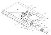
- FIG. 1illustrates an exemplary system that provides a suitable operating environment for the present invention
- FIG. 2is an exemplary connector interface illustrating a suitable socket and plug for the present invention
- FIG. 5illustrates a transparent bubbled connector plug
- the portable expansion device 14may be a modem, a network interface card, or any other card.
- the interface 22 of expansion device 14is configured to detachably connect with a high-speed connector (not shown) inside slot 12 . Inserting expansion device 14 in slot 12 permits expansion device 14 to be in electrical and physical communication with computer 10 .
- Jack 30is typically connected to a communication network, such as a telephone network, LAN, private branch exchange (PBX) system, or any type of computer network.
- PBXprivate branch exchange
- jack 30may be connected to a peripheral device, such as a scanner or SCSI hard drive array, controlled or driven by computer 10 via portable expansion device 14 .
- a selectively detachable connector assemblyelectrically and mechanically couples the cable and connector to the socket or media plug, more importantly however; the connector plug 130 optically aligns the light transfer medium 165 with an indicator interface 170 located on the exposed end of the PC card 114 .
- Optical alignment between the indicator interface 170 and the light transfer medium 165allow at least a fraction of the light emitted from the light interface to be transferred through the medium to a reflector 160 .
- Exemplary reflectorsinclude a molded reflector, prisms, mirrors, flexible light fibers, or other reflective material useful for redirecting the input light.
- the light transfer medium 165may consist of a transparent plastic material, a fiber optic cable, a light pipe, or other means of directing light in the direction of reflector 160 .
- connector socket 124comprises a plurality of I/O pins and a molded interface for receiving connector plug 130 .
- the I/O pinsare secured to a printed circuit board (PCB) 110 enclosed within the housing of the PC card 114 .
- PCBprinted circuit board
- I/O pins in socket 124 and plug 130will be in electrical communication with each other.
- a remotely illuminated electronic connector plug 130is inserted into a connector socket 124 , which is disposed between the external casings of the PC card 114 .
- Portions of the I/O pins and connector socket 124are secured to electrical contacts on the surface of the PCB 110 , thereby ensuring physical contact and electrical communication between the connector and the PCB circuitry.
- the socketfurther comprises a plurality of resilient conductive members that function to maintain physical and electrical contact between the connector socket 124 and the top and bottom portions of the external casing of the PC card 114 .
- Optical transmission via connector interface 116must not interfere with the electrical communications and may require shielding within the light transfer medium 165 of the connector plug 130 and the indicator interface 170 of the PC Card 114 .
- a functionally illuminated connector plug 130is a connector plug which, by way of simple illumination, specific illumination color, specific color combinations, intermittent illumination flashing patterns, color combination combined with flashing patterns or other illumination schemes, indicates an attribute of a device or system to which the connector plug is connected.
- One example of functional illuminationis a PC card LED indicator interface that contains two LEDs, typically of different colors. This type of connector interface is commonly used with a network adapter card where one LED is configured to illuminate thereby indicating that a signal is being received from the network while the second LED is configured to illuminate thereby indicating that network traffic or activity is present on the line.
- ⁇ illuminationis an illumination scheme used on some network adapters with optional topologies, such as a network adapter capable of providing access using speed or bandwidth topologies. These adapters may use a three LED scheme with one LED indicating network signal, another LED indicating a 10 Megabit per second capable connection, and the third LED indicating a 100 Megabit per second capable connection.
- Functional illuminationmay also indicate whether a card or peripheral device is inserted or connected properly.
- Functional illuminationmay also comprise illumination that indicates the location of the connector socket.
- the connector interface 116comprises a connector socket 124 and a light source or indicator interface 170 .
- the indicator interface 170is disposed between the external casings of the PC card in close proximity to the connector socket 124 .
- a light source 115 for indicator interface 170may include direct light from light emitting diodes, low power lamps, fluorescents, luminescents, or indirect light brought to the connector interface 116 via light transfer medium 120 , such as a light pipe 118 or light reflective material.
- the indicator interface 170may be suspended at the connector interface 116 or fixed to the connector socket 124 . The close proximity of the indicator interface 170 to the connector socket 124 enables the remotely illuminated connector plug 130 to redirect the light via light transfer medium 65 .
- light source 115radiates light into light pipe 118 that transmits the light to the rear surface of connector socket 124 where a receiver allows light to travel through light transfer medium 120 to indicator interface 170 .
- Indicator interface 170radiates light into a plug receiver that allows light to enter plug connector 130 and be transmitted via light transfer medium 165 to reflector 160 .
- Reflector 160focuses the light onto viewing window 150 and more specifically indicator dome 180 thereby illuminating viewing window 150 and indicator dome 180 .
- the light transfer medium 120could accept light from a second light source.
- the second light sourcecould radiate light into a second light pipe that either transmits the light to the first light receiver or to a second light receiver, which is a lens formed into backside surface of the light transfer medium 120 .
- the second light receiverdirects the light to a light redirector or interior light pipe which transmits or redirects the light to the front face of connector interface 116 where the light illuminates a selected section of the indicator interface 170 as a second functional indicator of the state or condition of the connection made with the PC Card 214 .
- light transfer mediumrefers to any physical conduit which may transmit light from one end to the other by optically guiding light along its length.
- a light pipeis an optical type of light transfer medium.
- Light pipesmay have a solid or hollow cross-section and may have a round, square or other cross-sectional shape.
- Solid light pipesare composed of translucent, highly transparent material through which light may pass without appreciable transmission losses.
- light pipesmay be composed of glass, polycarbonate or acrylic as well as many other materials.
- Hollow light pipesare typically constructed of highly reflective materials which reflect the light between interior surfaces, however, the interior surface of a hollow light pipe may also transmit light through a plurality of lenses which direct the light from the surface of the pipe back toward the center of the conduit. These lenses may vary in size from several inches to microscopic.
- Solid light pipesare typically coated with a reflective material to reflect light along the solid center conduit.
- Light transfer mediummay be rigid or flexible depending on the material used and the application.
- a light transfer mediumis typically continuous and homogenous throughout its length, however, it may be formed by a series of lenses spaced apart and configured so as to redirect light to the next lens in the series.
- a light transfer mediummay also be formed from a single light pipe conduit defined by a single outer reflective surface or a series of substantially parallel light pipe conduits forming a bundle.
- One example of the bundle type light pipe conduitis a typical fiber-optic cable bundle with a multiplicity of fibers capable of transmitting from one light source to a given destination. Both the bundle type conduit and the single conduit configurations work adequately in the present invention.
- solid polycarbonateare the preferable light transfer medium for fixed connectors as the material is rugged and stable in the range of temperatures encountered in electronic equipment and transmits light with minimal losses. Flexible fiber-optic cables are preferred for retractable connector systems.
- a preferred method of connector interface illuminationutilizes remotely located light sources from which light is transmitted to the connector socket 124 using one or more light pipes 118 .
- remote light source 115transmits light into light pipe 118 , which may bend in any direction to accommodate the necessity of elements in its path, eventually arriving at light pipe terminal end which directs light into a light receiver 120 on the indicator interface 170 to be illuminated.
- Light source 115may be any light source suitable for placement on a PCB such as an LED, a small incandescent or fluorescent lamp, or a lower-power laser.
- Light source 115may also be place off the PCB at another location in an electronic device and may comprise an LED, incandescent lamp, fluorescent lamp, laser or other light emitter or collector.
- Light pipe 118may be a solid, continuous, polycarbonate rod as in the preferred embodiment or any alternative light pipe embodiment as know in the art or described above.
- Light pipe terminal endmay be, for example, a solid, specially-polished termination of light pipe 118 as is known in the light pipe and fiber-optic art, or terminal end may form, as another example, a lens configured to transmit light into a light receiver 45 .
- the light receiveris located in or attached to a translucent body that acts to capture light and direct that light to a designated target, such as indicator interface 170 and light transfer medium 165 , which may be the receiving end of another light pipe or light transfer medium or it may be a light redirector 24 which may have one or more reflective or refractive surfaces for redirecting light to a specific location.
- light pipe 118transmits light into transfer medium 120 , which, in this example, is a polished, highly transparent surface which allows light emitted from light pipe 118 to strike reflective light redirector that directs the light longitudinally along the socket interior toward redirecting bevel face part of indicator interface 170 where the light exits thereby illuminating indicator interface 170 and any indicia thereon.
- transfer medium 120which, in this example, is a polished, highly transparent surface which allows light emitted from light pipe 118 to strike reflective light redirector that directs the light longitudinally along the socket interior toward redirecting bevel face part of indicator interface 170 where the light exits thereby illuminating indicator interface 170 and any indicia thereon.
- Light transfer medium 165then receives the light.
- viewing window 350 of connector plug 330includes a bubbled or rounded viewing indicator window 355 .
- the present inventionrelates to a connector plug 330 comprising one or more portions composed of translucent material that act as a light transfer medium 350 configured so as to be functionally illuminated by light directed to those portions of the connector plug 330 via one or more light interfaces 365 originating from a light source that may be located remotely from the connector plug 330 and associated analog circuitry associated with the peripheral device.
- Examples of a light source from which the light transfer medium 350 of the light interface 365 may originategiven by way of example and not limitation, may be an incandescent light, a Light Emitting Diode (LED) or a low power laser.
- LEDLight Emitting Diode
- the present inventionrelates to a computer communication connector plug 330 configured for insertion into a socket, the plug comprising one or more portions of substantially translucent material or other light transfer medium 350 .
- this socket and plug interfacemay take the form of an AC820 type connector interface.
- the light transfer medium 350is generally composed of substantially translucent material, preferably made of a unitary article such as a thermoplastic or a glass.
- unitary articleit is understood that the article is formed, molded, or machined from substantially a single piece of material.
- non-unitary articlesalso function effectively.
- the presently preferred material for the light transfer medium portionsis ULTEM®, a polyetherimide made by GE plastics of Pittsfield, Mass.
- Other suitable materialsinclude LEXAN 940A®, LEXAN 920®, and LEXAN 920A®, polysulphone, polyester, polyvinyl chloride (PVC), styrene acrylonitrile (SAN) and glass.
- the light transfer medium 350may act as a waveguide to alter the optical signal in a manner that intensifies the optical signal dispersion at bubbled viewing window 355 .
- the light transfer medium 350may also shield the data signals being transmitted received through connector plug 330 .
- Transparent connector 430contains a plug I/O interface with I/O pins 425 that facilitate transmission and reception of data via media cable 440 which passes through an optically shielded sleeve 445 .
- the optical interfaceconsists of a dispersion prism 410 located on the exposed connector plug end for interfacing with the light source of the expansion card. Dispersion prism 410 may refocus and intensify the light received from the light source and disperse the light signal or optical signal through the transparent connector 430 .
- the external shell of the transparent connector 430is beveled in a manner to reflect the optical signal and thereby increase the visual recognition of an individual looking at the transparent connector 430 .
- Rounded Reflector 460redirects reflected light back into the transparent connector 430 .
- FIG. 5an embodiment encompassing the advantages of a bubbled viewing angle and a transparent connector.
- An optical signalenters the transparent bubble connector 530 via dispersion prism 510 b which redirects and focuses the light to the central dispersion prism 510 a which reflects the optical signal via the light transfer medium 520 to the bubbled viewing window 555 which encompasses the entire transparent bubbled connector 530 .
- a curved reflector 560 located in the proximity of the media cable connection 540reflects any residual optical signal back towards the direction of the dispersion prism 510 a.
- the communication cablespass through the center of the transparent bubble connector 530 and may be shielded through the standard wire coating.
Landscapes
- Engineering & Computer Science (AREA)
- Microelectronics & Electronic Packaging (AREA)
- Details Of Connecting Devices For Male And Female Coupling (AREA)
Abstract
Description
Claims (7)
Priority Applications (1)
| Application Number | Priority Date | Filing Date | Title |
|---|---|---|---|
| US09/548,412US6361357B1 (en) | 2000-04-13 | 2000-04-13 | Remotely illuminated electronic connector for improving viewing of status indicators |
Applications Claiming Priority (1)
| Application Number | Priority Date | Filing Date | Title |
|---|---|---|---|
| US09/548,412US6361357B1 (en) | 2000-04-13 | 2000-04-13 | Remotely illuminated electronic connector for improving viewing of status indicators |
Publications (1)
| Publication Number | Publication Date |
|---|---|
| US6361357B1true US6361357B1 (en) | 2002-03-26 |
Family
ID=24188752
Family Applications (1)
| Application Number | Title | Priority Date | Filing Date |
|---|---|---|---|
| US09/548,412Expired - Fee RelatedUS6361357B1 (en) | 2000-04-13 | 2000-04-13 | Remotely illuminated electronic connector for improving viewing of status indicators |
Country Status (1)
| Country | Link |
|---|---|
| US (1) | US6361357B1 (en) |
Cited By (62)
| Publication number | Priority date | Publication date | Assignee | Title |
|---|---|---|---|---|
| US6574414B2 (en)* | 2001-01-08 | 2003-06-03 | 3Com Corporation | Light transmission apparatus and method |
| US20030193789A1 (en)* | 2002-04-16 | 2003-10-16 | Gelcore, Llc | Close packing LED assembly with versatile interconnect architecture |
| US20030212836A1 (en)* | 2002-05-10 | 2003-11-13 | Xerox Corporation | Customer replacement unit monitor programming cable |
| US20040005820A1 (en)* | 2001-03-16 | 2004-01-08 | Gutierrez Aurelio J. | Advanced microelectronic connector assembly and method of manufacturing |
| US20040029435A1 (en)* | 2002-08-08 | 2004-02-12 | Larson Thane M | Ejector latch indicator light and connector |
| US20040033716A1 (en)* | 2002-08-14 | 2004-02-19 | Bruce Musolf | Cross-connect jumper assembly having tracer lamp |
| US20040063502A1 (en)* | 2002-09-24 | 2004-04-01 | Intec, Inc. | Power module |
| US20040092164A1 (en)* | 2002-11-12 | 2004-05-13 | George Lee | Cable end connector assembly and the method of making the same |
| US20040117515A1 (en)* | 2002-11-15 | 2004-06-17 | Masuyuki Sago | Distributing system |
| US20040126065A1 (en)* | 2002-12-31 | 2004-07-01 | Levy Paul S. | Module interface with optical and electrical interconnects |
| US6783389B1 (en)* | 2003-08-14 | 2004-08-31 | Hon Hai Precision Ind. Co., Ltd. | Cable connector assembly having detecting contact |
| US20040224768A1 (en)* | 2002-09-24 | 2004-11-11 | Saied Hussaini | Video game controller with integrated status indicators |
| US20050023027A1 (en)* | 2003-08-01 | 2005-02-03 | Lin Jen Chien | Illuminating bus cable |
| US20050066103A1 (en)* | 2003-09-08 | 2005-03-24 | Nec Infrontia Corporation | PC card device with indicator having good visibility |
| US20050063647A1 (en)* | 2003-09-19 | 2005-03-24 | Thornton Martin Q. | Modular receptacle assembly and interface with integral optical indication |
| US20050101180A1 (en)* | 2003-11-06 | 2005-05-12 | Belkin Corporation | Electrical connector |
| US20050215110A1 (en)* | 2004-03-26 | 2005-09-29 | Wilson Chen | Indicator circuit arrangement of a transmission cable for computer |
| US20050215108A1 (en)* | 2004-03-26 | 2005-09-29 | Wilson Chen | Transmission cable for computer |
| EP1587020A1 (en)* | 2004-04-14 | 2005-10-19 | AboCom Systems, Inc. | Adapter for interface card |
| US20050245115A1 (en)* | 2004-02-04 | 2005-11-03 | Jory Bell | Docking cable |
| US20050266723A1 (en)* | 2004-06-01 | 2005-12-01 | Enterasys Networks, Inc. | Visual optical indicators for plug assemblies, connectors and cables |
| US20060044148A1 (en)* | 2004-09-02 | 2006-03-02 | International Business Machines Corporation | On-demand system for connector access independent of ambient light level |
| US7019658B1 (en) | 2003-03-04 | 2006-03-28 | Mobi Technologies, Inc. | Cable traffic indicator |
| US7101219B1 (en)* | 2005-12-20 | 2006-09-05 | Huang-Chou Huang | Adaptor with reflection fins |
| US20060286854A1 (en)* | 2005-05-31 | 2006-12-21 | Hon Hai Precision Ind. Co., Ltd. | Power connector with light indicator |
| US20070116411A1 (en)* | 2005-11-18 | 2007-05-24 | Mark Benton | Transceiver/fiber optic connector adaptor with patch cord id reading capability |
| US20070153499A1 (en)* | 2005-10-06 | 2007-07-05 | Church Walter E | Illuminating jewelry piece |
| US20070154135A1 (en)* | 2006-01-03 | 2007-07-05 | Delta Electronics, Inc. | Connector and indicator thereof |
| US20080007485A1 (en)* | 2006-07-05 | 2008-01-10 | Fujitsu Limited | Wireless connection device and wireless communication device |
| US20090221154A1 (en)* | 2006-03-17 | 2009-09-03 | Airbus Deutschland Gmbh | Fastening system for fastening a cabin fitting element to a support structure of an aircraft |
| WO2009117907A1 (en)* | 2008-03-24 | 2009-10-01 | 华为技术有限公司 | Optical transceiver module and optical fibre connector |
| US20090269962A1 (en)* | 2008-04-25 | 2009-10-29 | Tyco Electronics Corporation | Medical connector |
| WO2009111567A3 (en)* | 2008-03-04 | 2009-10-29 | Wegener David A | Computer cable connector protector |
| US20090280677A1 (en)* | 2008-05-07 | 2009-11-12 | Tyco Electronics Corporation | Illuminated circular plastic connector |
| US20100027310A1 (en)* | 2003-01-23 | 2010-02-04 | Micron Technology, Inc. | Apparatus and methods for optically-coupled memory systems |
| US20100144191A1 (en)* | 2004-06-29 | 2010-06-10 | Russell Lee Machado | Universal connector assembly and method of manufacturing |
| USD622216S1 (en) | 2008-12-12 | 2010-08-24 | Woodhead Industries, Inc. | Electrical connector with illumination |
| US20100330837A1 (en)* | 2009-03-04 | 2010-12-30 | David Wegener | Computer Cable Connector Protector |
| CN102208729A (en)* | 2010-03-30 | 2011-10-05 | 鸿富锦精密工业(深圳)有限公司 | Crystal head |
| US20120040554A1 (en)* | 2010-08-10 | 2012-02-16 | Hon Hai Precision Industry Co., Ltd. | Cable connector assembly with an improved light pipe and a method of assembling the cable connector assembly |
| US20120149234A1 (en)* | 2010-12-10 | 2012-06-14 | Hon Hai Precision Industry Co., Ltd. | Rj-45 connector |
| US20130009758A1 (en)* | 2011-07-07 | 2013-01-10 | International Business Machines Corporation | Tactile Visual Indicator |
| US20130078849A1 (en)* | 2011-09-23 | 2013-03-28 | Avaya Inc. | Connector illumination status |
| US20140069714A1 (en)* | 2012-09-11 | 2014-03-13 | Apple Inc. | Connector bracket |
| US20140140076A1 (en)* | 2012-11-20 | 2014-05-22 | Xentris Wireless, Llc | Illuminated interface cable |
| US8804354B2 (en) | 2012-09-11 | 2014-08-12 | Apple Inc. | Load sharing device and I/O architecture against imparted abuse loads |
| US8804353B2 (en) | 2012-09-11 | 2014-08-12 | Apple Inc. | Trim for input/output architecture in an electronic device |
| US9022605B2 (en) | 2011-09-08 | 2015-05-05 | Irving E. Bushnell | Charging connection device with illumination and associated methods |
| WO2015164101A1 (en)* | 2014-04-24 | 2015-10-29 | Western Digital Technologies, Inc. | Communications cable with status indicator for electronic devices |
| US20160104966A1 (en)* | 2014-10-09 | 2016-04-14 | Gbatteries Energy Inc. | Connectors for Delivery of Power |
| US20160149353A1 (en)* | 2014-11-25 | 2016-05-26 | Foxconn Interconnect Technology Limited | Cable connector assembly with improved indication effect |
| US20160240984A1 (en)* | 2015-02-13 | 2016-08-18 | Foxconn Interconnect Technology Limited | Plug connector assembly with light pipe and plural leds |
| US9460684B2 (en) | 2008-01-31 | 2016-10-04 | Hewlett-Packard Development Company, L.P. | System and method for illuminating connector ports |
| CN106450985A (en)* | 2016-11-30 | 2017-02-22 | 冯磊 | Intelligent socket |
| CN106684650A (en)* | 2016-12-09 | 2017-05-17 | 上海斐讯数据通信技术有限公司 | Transmission cable and mobile terminal adopting same |
| US9666974B2 (en) | 2014-02-10 | 2017-05-30 | Erbe Elektromedizin Gmbh | Socket insert for an electrosurgical device, electrosurgical device with a socket insert and set with a removal tool |
| US9859666B1 (en) | 2017-01-12 | 2018-01-02 | International Business Machines Corporation | Illuminated latch release for cable |
| US20180209918A1 (en)* | 2015-07-14 | 2018-07-26 | Synergx Technologies Inc. | Optical inspection system for transparent material |
| US10218200B2 (en) | 2012-03-25 | 2019-02-26 | Gbatteries Energy Canada Inc. | Systems and methods for enhancing the performance and utilization of battery systems |
| US10840725B2 (en) | 2016-07-10 | 2020-11-17 | Gbatteries Energy Canada Inc. | Battery charging with charging parameters sweep |
| US11606450B2 (en) | 2018-09-11 | 2023-03-14 | Apple Inc. | Structural support member for a data port of a device housing |
| US20230214344A1 (en)* | 2022-01-06 | 2023-07-06 | Dell Products L.P. | Provisioning connection information for display on cables used to couple devices |
Citations (51)
| Publication number | Priority date | Publication date | Assignee | Title |
|---|---|---|---|---|
| US2916720A (en) | 1957-08-14 | 1959-12-08 | Robert B Steans | Electrical connector |
| US4186988A (en) | 1978-09-20 | 1980-02-05 | Amp Incorporated | Electrical connector receptacles |
| US4241974A (en) | 1979-05-02 | 1980-12-30 | Western Electric Company, Inc. | Multi-outlet adapter for modular telephone cords |
| US4303296A (en) | 1978-05-03 | 1981-12-01 | Bunker Ramo Corporation | Modular interface connector |
| US4352492A (en) | 1976-08-23 | 1982-10-05 | Fairchild Camera & Instrument Corp. | Data storage apparatus |
| US4407559A (en) | 1981-04-09 | 1983-10-04 | Communications Systems, Inc. | Connector device with flush mounting receptacle, cover plate and terminal board |
| US4428636A (en) | 1981-11-05 | 1984-01-31 | Amp Incorporated | Multi-contact connectors for closely spaced conductors |
| US4564728A (en) | 1984-04-13 | 1986-01-14 | Comus International, Inc. | Apparatus for testing a telephone line |
| US4620070A (en) | 1985-02-04 | 1986-10-28 | Illinois Tool Works Inc. | Telephone line tester |
| JPS61256850A (en) | 1985-05-08 | 1986-11-14 | Fujitsu Ltd | Preventing plug for radio wave of telephone set |
| USD291071S (en) | 1985-03-28 | 1987-07-28 | Breil Randy J | Telephone line polarity tester |
| US4710136A (en) | 1982-02-26 | 1987-12-01 | Nippon Electric Co., Ltd. | Mounting structure for electronic apparatus or the like |
| DE3703423A1 (en)* | 1987-02-05 | 1988-08-25 | Kuhnke Gmbh Kg H | Multipole electric plug-in PCB connector device - comprises longitudinal plug housing and several electrical plug contacts joined to out-going cable cores |
| US4778410A (en) | 1986-09-22 | 1988-10-18 | Hosiden Electronics Co., Ltd. | Jack |
| US4915648A (en) | 1988-03-04 | 1990-04-10 | Fuji Jukogyo Kabushiki Kaisha | Connector with a lock mechanism |
| US5035641A (en) | 1988-02-15 | 1991-07-30 | Itt Industries Limited | Terminating insulated conductors |
| US5051099A (en) | 1990-01-10 | 1991-09-24 | Amp Incorporated | High speed card edge connector |
| US5139439A (en) | 1991-07-16 | 1992-08-18 | Veridata Electronics Inc. | Portable computer with detachable cartridge type interface device |
| US5184282A (en) | 1989-02-27 | 1993-02-02 | Mips Co., Ltd. | IC card adapter |
| US5183404A (en) | 1992-04-08 | 1993-02-02 | Megahertz Corporation | Systems for connection of physical/electrical media connectors to computer communications cards |
| US5391094A (en) | 1992-11-20 | 1995-02-21 | Murata Mfg. Co., Ltd. | Card-type line interface device |
| US5411405A (en) | 1993-11-12 | 1995-05-02 | Angia Communications, Inc. | Miniature electrical communications connectors |
| US5481440A (en)* | 1993-12-27 | 1996-01-02 | At&T Corp. | Circuit pack with light pipes |
| US5481616A (en) | 1993-11-08 | 1996-01-02 | Sparkomatic Corporation | Plug-in sound accessory for portable computers |
| US5499923A (en) | 1994-11-09 | 1996-03-19 | At&T Corp. | Communication card with extendible, rotatable coupling |
| US5505633A (en) | 1994-05-13 | 1996-04-09 | Intel Corporation | Integral external connector interface for thin form factor computer cards |
| US5509811A (en) | 1994-01-12 | 1996-04-23 | Dell Usa, L.P. | Computer enclosure with embedded PCMCIA modem card |
| US5513373A (en) | 1994-03-21 | 1996-04-30 | Motorola, Inc. | Apparatus using three light emitting diodes (LEDs) and a transistor for indicating whether there is an overtermination undertermination, or power termination of peripheral devices |
| US5521725A (en)* | 1993-11-05 | 1996-05-28 | Alliedsignal Inc. | Illumination system employing an array of microprisms |
| US5538442A (en) | 1993-10-04 | 1996-07-23 | Murata Mfg. Co., Ltd. | Communication card |
| US5547401A (en) | 1992-04-08 | 1996-08-20 | Megahertz Corporation | Media connector interface for use with a thin-architecture communications card |
| US5561727A (en) | 1994-02-15 | 1996-10-01 | Sumitomo Electric Industries, Ltd. | Card-shaped optical data link device |
| US5562504A (en) | 1995-01-04 | 1996-10-08 | Simple Technology Incorporated | Communications card with integral transmission media line adaptor |
| US5608607A (en) | 1995-04-24 | 1997-03-04 | Compaq Computer Corporation | PCMCIA card and associated support and circuitry augmenting apparatus and methods |
| US5634802A (en) | 1994-08-18 | 1997-06-03 | International Business Machines Corporation | Retractable expandable jack |
| US5646816A (en) | 1994-03-18 | 1997-07-08 | Lucent Technologies Inc. | Identification icon indicia for plug-in units of a power distribution system |
| US5660568A (en) | 1995-01-04 | 1997-08-26 | Simple Technology, Inc. | Communications card with integral transmission media line adaptor |
| US5667395A (en) | 1994-08-29 | 1997-09-16 | Murata Mfg. Co., Ltd. | Communication card and structure of jack for use in the same |
| US5679013A (en) | 1994-11-14 | 1997-10-21 | International Business Machines Corporation | Electrical connector and an electronic apparatus using the electrical connector |
| US5692914A (en) | 1995-01-24 | 1997-12-02 | Mitsubishi Denki Kabushiki Kaisha | PC card including a jack for a connector |
| US5741152A (en) | 1995-04-25 | 1998-04-21 | Amphenol Corporation | Electrical connector with indicator lights |
| US5767623A (en) | 1995-09-11 | 1998-06-16 | Planar Systems, Inc. | Interconnection between an active matrix electroluminescent display and an electrical cable |
| US5773332A (en) | 1993-11-12 | 1998-06-30 | Xircom, Inc. | Adaptable communications connectors |
| US5790041A (en) | 1995-02-14 | 1998-08-04 | Advanced Micro Devices, Inc. | Apparatus and method to display network connection status on a jack panel |
| US5797771A (en) | 1996-08-16 | 1998-08-25 | U.S. Robotics Mobile Communication Corp. | Cable connector |
| US5816832A (en) | 1992-04-08 | 1998-10-06 | 3Com Corporation | Media connector interface for use with a PCMCIA-architecture communications card |
| US5876239A (en) | 1996-08-30 | 1999-03-02 | The Whitaker Corporation | Electrical connector having a light indicator |
| US5885100A (en) | 1997-05-12 | 1999-03-23 | Molex Incorporated | Electrical connector with light transmission means |
| US6159037A (en)* | 1998-11-05 | 2000-12-12 | 3Com Corporation | Illuminated connector |
| US6229585B1 (en)* | 1997-10-21 | 2001-05-08 | Rohm Co., Ltd. | Liquid crystal display unit having light on one substrate illuminating edge of other |
| US6257906B1 (en)* | 1999-02-08 | 2001-07-10 | 3Com Corporation | Functionally illuminated electronic connector with improved light dispersion |
- 2000
- 2000-04-13USUS09/548,412patent/US6361357B1/ennot_activeExpired - Fee Related
Patent Citations (55)
| Publication number | Priority date | Publication date | Assignee | Title |
|---|---|---|---|---|
| US2916720A (en) | 1957-08-14 | 1959-12-08 | Robert B Steans | Electrical connector |
| US4352492A (en) | 1976-08-23 | 1982-10-05 | Fairchild Camera & Instrument Corp. | Data storage apparatus |
| US4303296A (en) | 1978-05-03 | 1981-12-01 | Bunker Ramo Corporation | Modular interface connector |
| US4186988A (en) | 1978-09-20 | 1980-02-05 | Amp Incorporated | Electrical connector receptacles |
| US4241974A (en) | 1979-05-02 | 1980-12-30 | Western Electric Company, Inc. | Multi-outlet adapter for modular telephone cords |
| US4407559A (en) | 1981-04-09 | 1983-10-04 | Communications Systems, Inc. | Connector device with flush mounting receptacle, cover plate and terminal board |
| US4428636A (en) | 1981-11-05 | 1984-01-31 | Amp Incorporated | Multi-contact connectors for closely spaced conductors |
| US4710136A (en) | 1982-02-26 | 1987-12-01 | Nippon Electric Co., Ltd. | Mounting structure for electronic apparatus or the like |
| US4564728A (en) | 1984-04-13 | 1986-01-14 | Comus International, Inc. | Apparatus for testing a telephone line |
| US4620070A (en) | 1985-02-04 | 1986-10-28 | Illinois Tool Works Inc. | Telephone line tester |
| USD291071S (en) | 1985-03-28 | 1987-07-28 | Breil Randy J | Telephone line polarity tester |
| JPS61256850A (en) | 1985-05-08 | 1986-11-14 | Fujitsu Ltd | Preventing plug for radio wave of telephone set |
| US4778410A (en) | 1986-09-22 | 1988-10-18 | Hosiden Electronics Co., Ltd. | Jack |
| DE3703423A1 (en)* | 1987-02-05 | 1988-08-25 | Kuhnke Gmbh Kg H | Multipole electric plug-in PCB connector device - comprises longitudinal plug housing and several electrical plug contacts joined to out-going cable cores |
| US5035641A (en) | 1988-02-15 | 1991-07-30 | Itt Industries Limited | Terminating insulated conductors |
| US4915648A (en) | 1988-03-04 | 1990-04-10 | Fuji Jukogyo Kabushiki Kaisha | Connector with a lock mechanism |
| US5184282A (en) | 1989-02-27 | 1993-02-02 | Mips Co., Ltd. | IC card adapter |
| US5051099A (en) | 1990-01-10 | 1991-09-24 | Amp Incorporated | High speed card edge connector |
| US5139439A (en) | 1991-07-16 | 1992-08-18 | Veridata Electronics Inc. | Portable computer with detachable cartridge type interface device |
| US5816832A (en) | 1992-04-08 | 1998-10-06 | 3Com Corporation | Media connector interface for use with a PCMCIA-architecture communications card |
| US5336099A (en) | 1992-04-08 | 1994-08-09 | Megahertz Corporation | Media connector interface for use with a PCMCIA-architecture communications card |
| US5338210A (en) | 1992-04-08 | 1994-08-16 | Megahertz Corporation | Media connector interface for use with a PCMCIA-architecture communications card |
| US5183404A (en) | 1992-04-08 | 1993-02-02 | Megahertz Corporation | Systems for connection of physical/electrical media connectors to computer communications cards |
| US5727972A (en) | 1992-04-08 | 1998-03-17 | Aldous; Stephen C. | Media connector interface for use with a thin-architecture communications card |
| US5547401A (en) | 1992-04-08 | 1996-08-20 | Megahertz Corporation | Media connector interface for use with a thin-architecture communications card |
| US5391094A (en) | 1992-11-20 | 1995-02-21 | Murata Mfg. Co., Ltd. | Card-type line interface device |
| US5538442A (en) | 1993-10-04 | 1996-07-23 | Murata Mfg. Co., Ltd. | Communication card |
| US5521725A (en)* | 1993-11-05 | 1996-05-28 | Alliedsignal Inc. | Illumination system employing an array of microprisms |
| US5481616A (en) | 1993-11-08 | 1996-01-02 | Sparkomatic Corporation | Plug-in sound accessory for portable computers |
| US5411405A (en) | 1993-11-12 | 1995-05-02 | Angia Communications, Inc. | Miniature electrical communications connectors |
| WO1995013633A1 (en) | 1993-11-12 | 1995-05-18 | Angia Communications, Inc. | Adaptable communications connectors |
| US5773332A (en) | 1993-11-12 | 1998-06-30 | Xircom, Inc. | Adaptable communications connectors |
| US5481440A (en)* | 1993-12-27 | 1996-01-02 | At&T Corp. | Circuit pack with light pipes |
| US5509811A (en) | 1994-01-12 | 1996-04-23 | Dell Usa, L.P. | Computer enclosure with embedded PCMCIA modem card |
| US5561727A (en) | 1994-02-15 | 1996-10-01 | Sumitomo Electric Industries, Ltd. | Card-shaped optical data link device |
| US5646816A (en) | 1994-03-18 | 1997-07-08 | Lucent Technologies Inc. | Identification icon indicia for plug-in units of a power distribution system |
| US5513373A (en) | 1994-03-21 | 1996-04-30 | Motorola, Inc. | Apparatus using three light emitting diodes (LEDs) and a transistor for indicating whether there is an overtermination undertermination, or power termination of peripheral devices |
| US5505633A (en) | 1994-05-13 | 1996-04-09 | Intel Corporation | Integral external connector interface for thin form factor computer cards |
| US5634802A (en) | 1994-08-18 | 1997-06-03 | International Business Machines Corporation | Retractable expandable jack |
| US5667395A (en) | 1994-08-29 | 1997-09-16 | Murata Mfg. Co., Ltd. | Communication card and structure of jack for use in the same |
| US5499923A (en) | 1994-11-09 | 1996-03-19 | At&T Corp. | Communication card with extendible, rotatable coupling |
| US5679013A (en) | 1994-11-14 | 1997-10-21 | International Business Machines Corporation | Electrical connector and an electronic apparatus using the electrical connector |
| US5660568A (en) | 1995-01-04 | 1997-08-26 | Simple Technology, Inc. | Communications card with integral transmission media line adaptor |
| US5562504A (en) | 1995-01-04 | 1996-10-08 | Simple Technology Incorporated | Communications card with integral transmission media line adaptor |
| US5692914A (en) | 1995-01-24 | 1997-12-02 | Mitsubishi Denki Kabushiki Kaisha | PC card including a jack for a connector |
| US5790041A (en) | 1995-02-14 | 1998-08-04 | Advanced Micro Devices, Inc. | Apparatus and method to display network connection status on a jack panel |
| US5608607A (en) | 1995-04-24 | 1997-03-04 | Compaq Computer Corporation | PCMCIA card and associated support and circuitry augmenting apparatus and methods |
| US5741152A (en) | 1995-04-25 | 1998-04-21 | Amphenol Corporation | Electrical connector with indicator lights |
| US5767623A (en) | 1995-09-11 | 1998-06-16 | Planar Systems, Inc. | Interconnection between an active matrix electroluminescent display and an electrical cable |
| US5797771A (en) | 1996-08-16 | 1998-08-25 | U.S. Robotics Mobile Communication Corp. | Cable connector |
| US5876239A (en) | 1996-08-30 | 1999-03-02 | The Whitaker Corporation | Electrical connector having a light indicator |
| US5885100A (en) | 1997-05-12 | 1999-03-23 | Molex Incorporated | Electrical connector with light transmission means |
| US6229585B1 (en)* | 1997-10-21 | 2001-05-08 | Rohm Co., Ltd. | Liquid crystal display unit having light on one substrate illuminating edge of other |
| US6159037A (en)* | 1998-11-05 | 2000-12-12 | 3Com Corporation | Illuminated connector |
| US6257906B1 (en)* | 1999-02-08 | 2001-07-10 | 3Com Corporation | Functionally illuminated electronic connector with improved light dispersion |
Non-Patent Citations (1)
| Title |
|---|
| P.E. Knight and D.R. Smith "Electrical Connector for Flat Flexible Cable," IBM Technical Disclosure Bulletin, vol. 25, No. 1, Jun. 1982. |
Cited By (116)
| Publication number | Priority date | Publication date | Assignee | Title |
|---|---|---|---|---|
| US6574414B2 (en)* | 2001-01-08 | 2003-06-03 | 3Com Corporation | Light transmission apparatus and method |
| US20040005820A1 (en)* | 2001-03-16 | 2004-01-08 | Gutierrez Aurelio J. | Advanced microelectronic connector assembly and method of manufacturing |
| US6962511B2 (en) | 2001-03-16 | 2005-11-08 | Pulse Engineering, Inc. | Advanced microelectronic connector assembly and method of manufacturing |
| US6851831B2 (en)* | 2002-04-16 | 2005-02-08 | Gelcore Llc | Close packing LED assembly with versatile interconnect architecture |
| US20030193789A1 (en)* | 2002-04-16 | 2003-10-16 | Gelcore, Llc | Close packing LED assembly with versatile interconnect architecture |
| US20030212836A1 (en)* | 2002-05-10 | 2003-11-13 | Xerox Corporation | Customer replacement unit monitor programming cable |
| US6952788B2 (en)* | 2002-05-10 | 2005-10-04 | Xerox Corporation | Customer replacement unit monitor programming cable |
| US20040029435A1 (en)* | 2002-08-08 | 2004-02-12 | Larson Thane M | Ejector latch indicator light and connector |
| US6908333B2 (en)* | 2002-08-08 | 2005-06-21 | Hewlett-Packard Development Company, L.P. | Ejector latch indicator light and connector |
| US6743044B2 (en)* | 2002-08-14 | 2004-06-01 | Adc Telecommunications, Inc. | Cross-connect jumper assembly having tracer lamp |
| US20040219825A1 (en)* | 2002-08-14 | 2004-11-04 | Adc Telecommunications, Inc. | Cross-connect jumper assembly having tracer lamp |
| US20040033716A1 (en)* | 2002-08-14 | 2004-02-19 | Bruce Musolf | Cross-connect jumper assembly having tracer lamp |
| US6905363B2 (en) | 2002-08-14 | 2005-06-14 | Adc Telecommunications, Inc. | Cross-connect jumper assembly having tracer lamp |
| US20040224768A1 (en)* | 2002-09-24 | 2004-11-11 | Saied Hussaini | Video game controller with integrated status indicators |
| US20040063502A1 (en)* | 2002-09-24 | 2004-04-01 | Intec, Inc. | Power module |
| US20040092164A1 (en)* | 2002-11-12 | 2004-05-13 | George Lee | Cable end connector assembly and the method of making the same |
| US6887104B2 (en) | 2002-11-12 | 2005-05-03 | Hon Hai Precision Ind. Co., Ltd. | Cable end connector assembly and the method of making the same |
| US20040117515A1 (en)* | 2002-11-15 | 2004-06-17 | Masuyuki Sago | Distributing system |
| US20040126065A1 (en)* | 2002-12-31 | 2004-07-01 | Levy Paul S. | Module interface with optical and electrical interconnects |
| US6793408B2 (en)* | 2002-12-31 | 2004-09-21 | Intel Corporation | Module interface with optical and electrical interconnects |
| US20100027310A1 (en)* | 2003-01-23 | 2010-02-04 | Micron Technology, Inc. | Apparatus and methods for optically-coupled memory systems |
| US8040711B2 (en)* | 2003-01-23 | 2011-10-18 | Round Rock Research, Llc | Apparatus and methods for optically-coupled memory systems |
| US8295071B2 (en) | 2003-01-23 | 2012-10-23 | Round Rock Research, Llc | Apparatus and methods for optically-coupled memory systems |
| US7019658B1 (en) | 2003-03-04 | 2006-03-28 | Mobi Technologies, Inc. | Cable traffic indicator |
| US20050023027A1 (en)* | 2003-08-01 | 2005-02-03 | Lin Jen Chien | Illuminating bus cable |
| US6783389B1 (en)* | 2003-08-14 | 2004-08-31 | Hon Hai Precision Ind. Co., Ltd. | Cable connector assembly having detecting contact |
| US20050066103A1 (en)* | 2003-09-08 | 2005-03-24 | Nec Infrontia Corporation | PC card device with indicator having good visibility |
| US20050063647A1 (en)* | 2003-09-19 | 2005-03-24 | Thornton Martin Q. | Modular receptacle assembly and interface with integral optical indication |
| US7194183B2 (en) | 2003-09-19 | 2007-03-20 | Enterasys Networks, Inc. | Modular receptacle assembly and interface with integral optical indication |
| US6921284B2 (en) | 2003-11-06 | 2005-07-26 | Belkin Corporation | Electrical connector |
| US20050101180A1 (en)* | 2003-11-06 | 2005-05-12 | Belkin Corporation | Electrical connector |
| US7285021B2 (en)* | 2004-02-04 | 2007-10-23 | Oqo, Inc. | Docking cable |
| US20050245115A1 (en)* | 2004-02-04 | 2005-11-03 | Jory Bell | Docking cable |
| WO2005076910A3 (en)* | 2004-02-04 | 2006-06-29 | Oqo Inc | Docking cable |
| US20050215108A1 (en)* | 2004-03-26 | 2005-09-29 | Wilson Chen | Transmission cable for computer |
| US6969273B2 (en)* | 2004-03-26 | 2005-11-29 | Wilson Chen | Transmission cable for computer |
| US20050215110A1 (en)* | 2004-03-26 | 2005-09-29 | Wilson Chen | Indicator circuit arrangement of a transmission cable for computer |
| US6979223B2 (en)* | 2004-03-26 | 2005-12-27 | Wilson Chen | Indicator circuit arrangement of a transmission cable for computer |
| EP1587020A1 (en)* | 2004-04-14 | 2005-10-19 | AboCom Systems, Inc. | Adapter for interface card |
| US20050266723A1 (en)* | 2004-06-01 | 2005-12-01 | Enterasys Networks, Inc. | Visual optical indicators for plug assemblies, connectors and cables |
| US7137743B2 (en)* | 2004-06-01 | 2006-11-21 | Enterasys Networks, Inc. | Visual optical indicators for plug assemblies, connectors and cables |
| US8480440B2 (en) | 2004-06-29 | 2013-07-09 | Pulse Electronics, Inc. | Universal connector assembly and method of manufacturing |
| US7786009B2 (en) | 2004-06-29 | 2010-08-31 | Pulse Engineering, Inc. | Universal connector assembly and method of manufacturing |
| US8206183B2 (en) | 2004-06-29 | 2012-06-26 | Pulse Electronics, Inc. | Universal connector assembly and method of manufacturing |
| US20100144191A1 (en)* | 2004-06-29 | 2010-06-10 | Russell Lee Machado | Universal connector assembly and method of manufacturing |
| US8882546B2 (en) | 2004-06-29 | 2014-11-11 | Pulse Electronics, Inc. | Universal connector assembly and method of manufacturing |
| US7959473B2 (en) | 2004-06-29 | 2011-06-14 | Pulse Engineering, Inc. | Universal connector assembly and method of manufacturing |
| US20110059647A1 (en)* | 2004-06-29 | 2011-03-10 | Russell Lee Machado | Universal Connector Assembly and Method of Manufacturing |
| US20060044148A1 (en)* | 2004-09-02 | 2006-03-02 | International Business Machines Corporation | On-demand system for connector access independent of ambient light level |
| US7168975B2 (en)* | 2005-05-31 | 2007-01-30 | Hon Hai Precision Ind. Co., Ltd. | Power connector with light indicator |
| US20060286854A1 (en)* | 2005-05-31 | 2006-12-21 | Hon Hai Precision Ind. Co., Ltd. | Power connector with light indicator |
| US20070153499A1 (en)* | 2005-10-06 | 2007-07-05 | Church Walter E | Illuminating jewelry piece |
| CN101356464B (en)* | 2005-11-18 | 2010-08-18 | 斯特拉托斯国际公司 | Devices and transceivers that facilitate identification of specific connectors or cables |
| US20070116411A1 (en)* | 2005-11-18 | 2007-05-24 | Mark Benton | Transceiver/fiber optic connector adaptor with patch cord id reading capability |
| US7226217B1 (en)* | 2005-11-18 | 2007-06-05 | Stratos International, Inc. | Transceiver/fiber optic connector adaptor with patch cord ID reading capability |
| WO2007061490A3 (en)* | 2005-11-18 | 2007-07-12 | Stratos Int Inc | Transceiver/fiber optic connector adaptor with patch cord id reading capability |
| US7101219B1 (en)* | 2005-12-20 | 2006-09-05 | Huang-Chou Huang | Adaptor with reflection fins |
| US20070154135A1 (en)* | 2006-01-03 | 2007-07-05 | Delta Electronics, Inc. | Connector and indicator thereof |
| US20090221154A1 (en)* | 2006-03-17 | 2009-09-03 | Airbus Deutschland Gmbh | Fastening system for fastening a cabin fitting element to a support structure of an aircraft |
| US8167624B2 (en)* | 2006-03-17 | 2012-05-01 | Airbus Operations Gmbh | Fastening system for fastening a cabin fitting element to a support structure of an aircraft |
| US8588769B2 (en)* | 2006-07-05 | 2013-11-19 | Fujitsu Limited | Wireless connection device and wireless communication device |
| US20080007485A1 (en)* | 2006-07-05 | 2008-01-10 | Fujitsu Limited | Wireless connection device and wireless communication device |
| US9460684B2 (en) | 2008-01-31 | 2016-10-04 | Hewlett-Packard Development Company, L.P. | System and method for illuminating connector ports |
| WO2009111567A3 (en)* | 2008-03-04 | 2009-10-29 | Wegener David A | Computer cable connector protector |
| WO2009117907A1 (en)* | 2008-03-24 | 2009-10-01 | 华为技术有限公司 | Optical transceiver module and optical fibre connector |
| WO2009131611A1 (en)* | 2008-04-25 | 2009-10-29 | Tyco Electronics Corporation | Medical connector |
| US20090269962A1 (en)* | 2008-04-25 | 2009-10-29 | Tyco Electronics Corporation | Medical connector |
| US7758369B2 (en) | 2008-04-25 | 2010-07-20 | Tyco Electronics Corporation | Plug connector for use with a receptacle |
| US20090280677A1 (en)* | 2008-05-07 | 2009-11-12 | Tyco Electronics Corporation | Illuminated circular plastic connector |
| USD622216S1 (en) | 2008-12-12 | 2010-08-24 | Woodhead Industries, Inc. | Electrical connector with illumination |
| US20100330837A1 (en)* | 2009-03-04 | 2010-12-30 | David Wegener | Computer Cable Connector Protector |
| US8435067B2 (en) | 2009-03-04 | 2013-05-07 | David Wegener | Computer cable connector protector |
| CN102208729B (en)* | 2010-03-30 | 2013-11-06 | 鸿富锦精密工业(深圳)有限公司 | Crystal head |
| CN102208729A (en)* | 2010-03-30 | 2011-10-05 | 鸿富锦精密工业(深圳)有限公司 | Crystal head |
| US8333608B2 (en)* | 2010-08-10 | 2012-12-18 | Hon Hai Precision Ind. Co., Ltd | Cable connector having a light pipe having two different sections with different color characteristics |
| US20120040554A1 (en)* | 2010-08-10 | 2012-02-16 | Hon Hai Precision Industry Co., Ltd. | Cable connector assembly with an improved light pipe and a method of assembling the cable connector assembly |
| US8241056B2 (en)* | 2010-12-10 | 2012-08-14 | Hon Hai Precision Industry Co., Ltd. | RJ-45 connector |
| US20120149234A1 (en)* | 2010-12-10 | 2012-06-14 | Hon Hai Precision Industry Co., Ltd. | Rj-45 connector |
| US20130009758A1 (en)* | 2011-07-07 | 2013-01-10 | International Business Machines Corporation | Tactile Visual Indicator |
| US8736431B2 (en)* | 2011-07-07 | 2014-05-27 | International Business Machines Corporation | Tactile visual indicator |
| US9022605B2 (en) | 2011-09-08 | 2015-05-05 | Irving E. Bushnell | Charging connection device with illumination and associated methods |
| US20130078849A1 (en)* | 2011-09-23 | 2013-03-28 | Avaya Inc. | Connector illumination status |
| US10218200B2 (en) | 2012-03-25 | 2019-02-26 | Gbatteries Energy Canada Inc. | Systems and methods for enhancing the performance and utilization of battery systems |
| US11050281B2 (en) | 2012-03-25 | 2021-06-29 | Gbatteries Energy, Inc. | Systems and methods for enhancing the performance and utilization of battery systems |
| US11973195B2 (en) | 2012-03-25 | 2024-04-30 | Gbatteries Energy Canada Inc. | Reconfigurable multi-core battery packs |
| US8804354B2 (en) | 2012-09-11 | 2014-08-12 | Apple Inc. | Load sharing device and I/O architecture against imparted abuse loads |
| US20140069714A1 (en)* | 2012-09-11 | 2014-03-13 | Apple Inc. | Connector bracket |
| US9288928B2 (en) | 2012-09-11 | 2016-03-15 | Apple Inc. | Load sharing device and I/O architecture against imparted abuse loads |
| US8804355B2 (en)* | 2012-09-11 | 2014-08-12 | Apple Inc. | Connector bracket |
| US8804353B2 (en) | 2012-09-11 | 2014-08-12 | Apple Inc. | Trim for input/output architecture in an electronic device |
| US9099856B2 (en) | 2012-09-11 | 2015-08-04 | Apple Inc. | Connector bracket |
| US20140140076A1 (en)* | 2012-11-20 | 2014-05-22 | Xentris Wireless, Llc | Illuminated interface cable |
| US9666974B2 (en) | 2014-02-10 | 2017-05-30 | Erbe Elektromedizin Gmbh | Socket insert for an electrosurgical device, electrosurgical device with a socket insert and set with a removal tool |
| RU2628623C2 (en)* | 2014-02-10 | 2017-08-21 | Эрбе Электромедицин Гмбх | Electrosurgical device with nest insert, set including nest insert and instrument for extraction and method of extracting nest insert |
| CN106233398A (en)* | 2014-04-24 | 2016-12-14 | 西部数据技术公司 | The communication cable with positioning indicator for electronic equipment |
| US9893476B2 (en) | 2014-04-24 | 2018-02-13 | Western Digital Technologies, Inc. | Communications cable with status indicator for electronic devices |
| WO2015164101A1 (en)* | 2014-04-24 | 2015-10-29 | Western Digital Technologies, Inc. | Communications cable with status indicator for electronic devices |
| US9608386B2 (en) | 2014-04-24 | 2017-03-28 | Western Digital Technologies, Inc. | Communications cable with status indicator for electronic devices |
| CN106233398B (en)* | 2014-04-24 | 2018-12-04 | 西部数据技术公司 | Communication cable for electronic equipment with positioning indicator |
| US10109962B2 (en) | 2014-04-24 | 2018-10-23 | Western Digital Technologies, Inc. | Communications cable with status indicator for electronic devices |
| US20160104966A1 (en)* | 2014-10-09 | 2016-04-14 | Gbatteries Energy Inc. | Connectors for Delivery of Power |
| US10020608B2 (en)* | 2014-10-09 | 2018-07-10 | Gbatteries Energy Canada Inc. | Connectors for delivery of power |
| US20160149353A1 (en)* | 2014-11-25 | 2016-05-26 | Foxconn Interconnect Technology Limited | Cable connector assembly with improved indication effect |
| US9660396B2 (en)* | 2014-11-25 | 2017-05-23 | Foxconn Interconnect Technology Limited | Cable connector assembly with improved indication effect |
| US20160240984A1 (en)* | 2015-02-13 | 2016-08-18 | Foxconn Interconnect Technology Limited | Plug connector assembly with light pipe and plural leds |
| US9705263B2 (en)* | 2015-02-13 | 2017-07-11 | Foxconn Interconnect Technology Limited | Plug connector assembly with light pipe and plural LEDs |
| US20180209918A1 (en)* | 2015-07-14 | 2018-07-26 | Synergx Technologies Inc. | Optical inspection system for transparent material |
| US10840725B2 (en) | 2016-07-10 | 2020-11-17 | Gbatteries Energy Canada Inc. | Battery charging with charging parameters sweep |
| US11362535B2 (en) | 2016-07-10 | 2022-06-14 | Gbatteries Energy Canada Inc. | Battery charging with charging parameters sweep |
| CN106450985A (en)* | 2016-11-30 | 2017-02-22 | 冯磊 | Intelligent socket |
| CN106684650A (en)* | 2016-12-09 | 2017-05-17 | 上海斐讯数据通信技术有限公司 | Transmission cable and mobile terminal adopting same |
| US10170873B2 (en) | 2017-01-12 | 2019-01-01 | International Business Machines Corporation | Illuminated latch release for cable |
| US9859666B1 (en) | 2017-01-12 | 2018-01-02 | International Business Machines Corporation | Illuminated latch release for cable |
| US11606450B2 (en) | 2018-09-11 | 2023-03-14 | Apple Inc. | Structural support member for a data port of a device housing |
| US20230214344A1 (en)* | 2022-01-06 | 2023-07-06 | Dell Products L.P. | Provisioning connection information for display on cables used to couple devices |
| US11720514B2 (en)* | 2022-01-06 | 2023-08-08 | Dell Products L.P. | Provisioning connection information for display on cables used to couple devices |
Similar Documents
| Publication | Publication Date | Title |
|---|---|---|
| US6361357B1 (en) | Remotely illuminated electronic connector for improving viewing of status indicators | |
| US6457992B2 (en) | Visual feedback system for electronic device | |
| US6257906B1 (en) | Functionally illuminated electronic connector with improved light dispersion | |
| US20150380879A1 (en) | Lighted electrical interconnect assembly | |
| EP1116306B1 (en) | Status indicator for electronic device | |
| US9028122B2 (en) | Lighted electrical connector assembly | |
| US6483712B1 (en) | Illuminating electrical jack system | |
| US8118497B2 (en) | Connector utilized for different kinds of signal transmition | |
| US8152569B2 (en) | Extension to version 2.0 universal serial bus connector with additional contacts | |
| US5473715A (en) | Hybrid fiber optic/electrical connector | |
| US7828569B2 (en) | Receptacle with multiple contact sets for different connector types | |
| US20090027874A1 (en) | Illumination device and portable electronic device incorporating same | |
| US20050063647A1 (en) | Modular receptacle assembly and interface with integral optical indication | |
| US10436395B2 (en) | Flexible illuminating flat cable structure | |
| US7255488B1 (en) | Network element connector assembly including stacked electrical and optical connector interfaces | |
| US20030002810A1 (en) | Illuminating optical fiber plug | |
| US10116105B2 (en) | Illuminated printed circuit boards for connectors | |
| US20070072491A1 (en) | Integrated signal connecting port | |
| US8746990B2 (en) | Universal modular connector | |
| US20030151891A1 (en) | Universal cableless drive adapter for a portable computer data storage device | |
| TW202030944A (en) | Host illumination of indicators of an ac adapter | |
| CN220731942U (en) | Data line connector and data transmission line | |
| TWI880206B (en) | Light-emitting electrical connector | |
| CN216697249U (en) | Interactive device | |
| CN215182890U (en) | Luminous lamp box |
Legal Events
| Date | Code | Title | Description |
|---|---|---|---|
| AS | Assignment | Owner name:3COM CORPORATION, CALIFORNIA Free format text:ASSIGNMENT OF ASSIGNORS INTEREST;ASSIGNORS:STILLWELL, KAYLENE C.;NELSON, JON A.;REEL/FRAME:010715/0356 Effective date:20000405 | |
| FPAY | Fee payment | Year of fee payment:4 | |
| FPAY | Fee payment | Year of fee payment:8 | |
| AS | Assignment | Owner name:HEWLETT-PACKARD COMPANY, CALIFORNIA Free format text:MERGER;ASSIGNOR:3COM CORPORATION;REEL/FRAME:024630/0820 Effective date:20100428 | |
| AS | Assignment | Owner name:HEWLETT-PACKARD COMPANY, CALIFORNIA Free format text:CORRECTIVE ASSIGNMENT TO CORRECT THE SEE ATTACHED;ASSIGNOR:3COM CORPORATION;REEL/FRAME:025039/0844 Effective date:20100428 | |
| AS | Assignment | Owner name:HEWLETT-PACKARD DEVELOPMENT COMPANY, L.P., TEXAS Free format text:ASSIGNMENT OF ASSIGNORS INTEREST;ASSIGNOR:HEWLETT-PACKARD COMPANY;REEL/FRAME:027329/0044 Effective date:20030131 | |
| AS | Assignment | Owner name:HEWLETT-PACKARD DEVELOPMENT COMPANY, L.P., TEXAS Free format text:CORRECTIVE ASSIGNMENT PREVIUOSLY RECORDED ON REEL 027329 FRAME 0001 AND 0044;ASSIGNOR:HEWLETT-PACKARD COMPANY;REEL/FRAME:028911/0846 Effective date:20111010 | |
| REMI | Maintenance fee reminder mailed | ||
| LAPS | Lapse for failure to pay maintenance fees | ||
| STCH | Information on status: patent discontinuation | Free format text:PATENT EXPIRED DUE TO NONPAYMENT OF MAINTENANCE FEES UNDER 37 CFR 1.362 | |
| FP | Lapsed due to failure to pay maintenance fee | Effective date:20140326 |