US6360886B1 - Capsule for use in preparing a dental amalgam - Google Patents
Capsule for use in preparing a dental amalgamDownload PDFInfo
- Publication number
- US6360886B1 US6360886B1US09/524,403US52440300AUS6360886B1US 6360886 B1US6360886 B1US 6360886B1US 52440300 AUS52440300 AUS 52440300AUS 6360886 B1US6360886 B1US 6360886B1
- Authority
- US
- United States
- Prior art keywords
- capsule
- cap
- dental amalgam
- annular recess
- end wall
- Prior art date
- Legal status (The legal status is an assumption and is not a legal conclusion. Google has not performed a legal analysis and makes no representation as to the accuracy of the status listed.)
- Expired - Lifetime
Links
- 239000002775capsuleSubstances0.000titleclaimsabstractdescription100
- 239000000448dental amalgamSubstances0.000titleclaimsabstractdescription40
- 229910001312Amalgam (dentistry)Inorganic materials0.000titleclaimsabstractdescription39
- 238000007789sealingMethods0.000claimsabstractdescription64
- 229910045601alloyInorganic materials0.000claimsabstractdescription18
- 239000000956alloySubstances0.000claimsabstractdescription18
- QSHDDOUJBYECFT-UHFFFAOYSA-NmercuryChemical compound[Hg]QSHDDOUJBYECFT-UHFFFAOYSA-N0.000claimsabstractdescription18
- 229910052753mercuryInorganic materials0.000claimsabstractdescription18
- 238000002156mixingMethods0.000claimsdescription14
- 238000000034methodMethods0.000claimsdescription12
- 230000007423decreaseEffects0.000claimsdescription9
- 229910000497AmalgamInorganic materials0.000claimsdescription8
- 239000000203mixtureSubstances0.000claimsdescription8
- 239000000843powderSubstances0.000claimsdescription7
- 230000002401inhibitory effectEffects0.000claims3
- 230000000149penetrating effectEffects0.000claims3
- 230000000295complement effectEffects0.000claims1
- 230000003247decreasing effectEffects0.000claims1
- 230000002093peripheral effectEffects0.000description45
- 239000000463materialSubstances0.000description10
- 238000007373indentationMethods0.000description8
- 238000005267amalgamationMethods0.000description3
- 230000008901benefitEffects0.000description3
- 230000007246mechanismEffects0.000description3
- 230000008569processEffects0.000description3
- NXALGSLCQTXAKO-UHFFFAOYSA-N[Cu].[Cu].[Cu].[Cu].[Cu].[Cu].[Cu].[Cu].[Cu].[Cu].[Cu].[Cu].[Cu].[Ag].[Ag].[Ag].[Ag].[Ag].[Ag].[Ag].[Ag].[Ag].[Ag].[Ag].[Ag].[Ag].[Ag].[Ag].[Ag].[Ag].[Ag].[Ag].[Ag].[Ag].[Ag].[Ag].[Ag].[Ag].[Ag].[Ag].[Ag].[Ag].[Ag].[Ag].[Ag].[Ag].[Ag].[Ag].[Ag].[Ag].[Ag].[Ag].[Ag].[Ag].[Ag].[Ag].[Ag].[Ag].[Ag].[Ag].[Ag].[Ag].[Ag].[Ag].[Ag].[Ag].[Ag].[Ag].[Ag].[Ag].[Ag].[Ag].[Sn].[Sn].[Sn].[Sn].[Sn].[Sn].[Sn].[Sn].[Sn].[Sn].[Sn].[Sn].[Sn].[Sn].[Sn].[Sn].[Sn].[Sn].[Sn].[Sn].[Sn].[Sn].[Sn].[Sn].[Sn].[Sn].[Sn].[Sn]Chemical compound[Cu].[Cu].[Cu].[Cu].[Cu].[Cu].[Cu].[Cu].[Cu].[Cu].[Cu].[Cu].[Cu].[Ag].[Ag].[Ag].[Ag].[Ag].[Ag].[Ag].[Ag].[Ag].[Ag].[Ag].[Ag].[Ag].[Ag].[Ag].[Ag].[Ag].[Ag].[Ag].[Ag].[Ag].[Ag].[Ag].[Ag].[Ag].[Ag].[Ag].[Ag].[Ag].[Ag].[Ag].[Ag].[Ag].[Ag].[Ag].[Ag].[Ag].[Ag].[Ag].[Ag].[Ag].[Ag].[Ag].[Ag].[Ag].[Ag].[Ag].[Ag].[Ag].[Ag].[Ag].[Ag].[Ag].[Ag].[Ag].[Ag].[Ag].[Ag].[Ag].[Sn].[Sn].[Sn].[Sn].[Sn].[Sn].[Sn].[Sn].[Sn].[Sn].[Sn].[Sn].[Sn].[Sn].[Sn].[Sn].[Sn].[Sn].[Sn].[Sn].[Sn].[Sn].[Sn].[Sn].[Sn].[Sn].[Sn].[Sn]NXALGSLCQTXAKO-UHFFFAOYSA-N0.000description2
- 230000009471actionEffects0.000description2
- MKWYFZFMAMBPQK-UHFFFAOYSA-Jsodium feredetateChemical compound[Na+].[Fe+3].[O-]C(=O)CN(CC([O-])=O)CCN(CC([O-])=O)CC([O-])=OMKWYFZFMAMBPQK-UHFFFAOYSA-J0.000description2
- 239000000126substanceSubstances0.000description2
- 239000004698PolyethyleneSubstances0.000description1
- KSUSASQMNVMCES-UHFFFAOYSA-N[Cu].[Cu].[Cu].[Ag].[Ag].[Ag].[Ag].[Sn].[Sn].[Sn]Chemical compound[Cu].[Cu].[Cu].[Ag].[Ag].[Ag].[Ag].[Sn].[Sn].[Sn]KSUSASQMNVMCES-UHFFFAOYSA-N0.000description1
- 230000001133accelerationEffects0.000description1
- 239000000853adhesiveSubstances0.000description1
- 230000001070adhesive effectEffects0.000description1
- 238000010276constructionMethods0.000description1
- 238000013038hand mixingMethods0.000description1
- 229920005669high impact polystyrenePolymers0.000description1
- 239000004797high-impact polystyreneSubstances0.000description1
- 238000001746injection mouldingMethods0.000description1
- 238000004519manufacturing processMethods0.000description1
- 230000004048modificationEffects0.000description1
- 238000012986modificationMethods0.000description1
- -1polyethylenePolymers0.000description1
- 229920000573polyethylenePolymers0.000description1
- 230000002028prematureEffects0.000description1
- 238000004513sizingMethods0.000description1
- 229920001169thermoplasticPolymers0.000description1
- 239000004416thermosoftening plasticSubstances0.000description1
- 230000007704transitionEffects0.000description1
- 238000011179visual inspectionMethods0.000description1
Images


Classifications
- A—HUMAN NECESSITIES
- A61—MEDICAL OR VETERINARY SCIENCE; HYGIENE
- A61C—DENTISTRY; APPARATUS OR METHODS FOR ORAL OR DENTAL HYGIENE
- A61C5/00—Filling or capping teeth
- A61C5/60—Devices specially adapted for pressing or mixing capping or filling materials, e.g. amalgam presses
- A61C5/66—Capsules for filling material
Definitions
- This inventionrelates to a capsule for use in preparing a dental amalgam, and more particularly, to such a capsule which may be opened to inspect the contents following amalgamation, and, if necessary, securely resealed for further amalgamation.
- Such capsule systemstypically include a body portion and a removable cap portion which combine to form a mixing chamber.
- Such capsule systemsfurther include an amalgam alloy and mercury, with the mercury being kept separate from the alloy until the dental professional is ready to form the particular amalgam.
- a mercury-containing bag or pouchis placed in the chamber body, along with the particular dental amalgam alloy.
- the chamber body and chamber capthen are welded together, or bonded together using a suitable adhesive or other bonding material.
- the particular capsuleis placed in an amalgamator, also known as a vibration mixer, which moves the capsule backward and forward at extremely high speeds, generally in a direction which is along the longitudinal axis of the capsule system.
- the mercury-containing bag or pouchis designed to rupture or burst due to the reversing forces of the amalgamator.
- the dental professionalbreaks the seal on the capsule system in order to gain access to the contents of the mixing chamber.
- the dental professionalbreaks the seal by inserting one end of a cylindrical rod into a corresponding cylindrical socket formed on the top of the cap portion. Then, by using the cylindrical rod as a lever, the professional may break the cap portion away from the body portion, and subsequently empty the contents of the mixing chamber into a dental amalgam basin.
- this breaking processis awkward, and may cause accidental spilling of the contents.
- the body portion and cap portionare welded or bonded together, the risk of premature leakage of mercury is relatively low. However, once the seal between body and cap has been broken, the capsule system may not be placed back in the amalgamator for further mixing, which is a significant drawback.
- the inventionovercomes the above-mentioned drawbacks by providing a capsule kit having a first capsule member and a second capsule member, in which the first capsule member has a peripheral end wall, and the second capsule member has a corresponding peripheral recess capable of forming a secure, releasable, resealable seal between the first and second capsule members, thereby enabling a dental professional to open the capsule, inspect the contents of the mixing chamber, and, if necessary, reseal the capsule, and place it back in the amalgamator for continued mixing.
- the first capsule memberhas an exterior surface, an interior surface, an opening, an interior space and a first end, with the first end having the peripheral end wall.
- the peripheral end wallincludes a width, an inner edge, an outer edge, and a surface which inclines in the direction of the outer edge.
- the second capsule memberhas an exterior surface, an interior surface, an opening, an interior space, and a first end, with the interior surface including the peripheral recess which forms the releasable, yet resealable, seal with the peripheral end wall.
- the peripheral end wallhas a non-contacting portion which is adjacent the inner edge, with the non-contacting portion being in non-contacting relationship with the peripheral recess when the peripheral end wall and the peripheral recess form a seal.
- the peripheral recessincludes an upper wall having a projecting end which projects toward a central, longitudinal axis of the second capsule member. The distance between the projecting end and the central, longitudinal axis is greater than the distance between the first capsule member end wall inner edge and the central, longitudinal axis, when the peripheral end wall and the peripheral recess form a releasable seal.
- the peripheral recessincludes an upper wall having a length, with the length of the peripheral end wall being greater than the length of the peripheral recess upper wall.
- the peripheral end wall surface which inclines in the direction of the outer edgeis substantially planar, and the peripheral recess has an upper wall which also is substantially planar.
- the peripheral end wallhas a receivable portion which is received by the peripheral recess.
- the receivable portionincludes the peripheral end wall outer edge, an adjacent inner surface, an adjacent outer surface, and a cross-sectional shape having a first angle formed between the adjacent inner surface and the adjacent outer surface.
- the peripheral recessincludes a base, an adjacent upper wall, an adjacent sidewall, and a cross-sectional shape having a second angle formed between the adjacent upper wall and the adjacent sidewall, with the first angle being greater than the second angle.
- the peripheral recessmay be made such that it is more flexible than the receivable portion.
- the angle of the peripheral recessmay be smaller than the angle of the receivable portion, the added flexibility gives the peripheral recess a bit of a spring action, assisting it in biasing against the receivable portion, thereby improving the integrity of the seal.
- the first capsule memberfurther includes a peripheral flange which extends from the exterior surface.
- This peripheral flangehas a cross-sectional diameter which increases in the direction of the first end of the first capsule member.
- the peripheral flangemay have a sidewall which is substantially planar.
- the peripheral flangemay have an upper ledge.
- the first capsule memberincludes a peripheral flange extending from the exterior surface
- the second capsule memberincludes a peripheral, generally V-shaped indentation along the interior surface, with the indentation having a first sidewall.
- This peripheral, generally V-shaped indentationis capable of releasably engaging the peripheral flange.
- the inner diameter of the second capsule member, along the indentation first sidewallmay decrease in the direction of the first end of the second capsule member.
- the outer diameter of the peripheral flangemay decrease in the direction away from the first end of the first capsule member, with this decrease being at a rate substantially similar to a rate of decrease of the inner diameter of the second capsule member, along the indentation first sidewall, in the direction of the first end of the second capsule member.
- peripheral flange and the peripheral, generally V-shaped indentation discussed briefly aboveprovide a dental practitioner with an easy-to-use, snap-fit securing system. In this fashion, a dental professional knows that the first and second capsule members are releasably secured together by feeling the snap-like aspect of this feature.
- the peripheral flange and peripheral, generally V-shaped indentationare designed so that a user easily may separate the first capsule member from the second capsule member.
- these aspects of the inventionare designed to ensure that a tight, releasable, resealable, seal is formed between the peripheral end wall and the peripheral recess of the first capsule member and second capsule member, respectively.
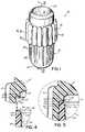
- FIG. 1is a perspective view of one version of the capsule in accordance with the principles of the invention
- FIG. 2is a disassembled, cross-sectional view of the capsule of FIG. 1, taken along line 2 — 2 of FIG. 1;
- FIG. 3is a cross-sectional view of the capsule of FIG. 1;
- FIG. 4is an enlarged, cross-sectional view of a portion of the capsule of FIG. 2;
- FIG. 5is an enlarged, cross-sectional view of a portion of the capsule of FIG. 3 .
- a version 10 of the capsule for use in forming a dental amalgamincludes a body 12 , a cap 14 , an amalgam alloy powder 16 , and a mercury-containing pillow pack 18 , also referred to as a bag, pocket, or pouch.
- the body 12is substantially cylindrical in nature, having an open first end 20 and an oppositely positioned, closed second end 22 , with a generally cylindrical, circumferential sidewall 24 extending between the first and second ends 20 , 22 .
- the first end 20includes an opening 21 which leads to an interior space 23 and an interior surface 26 , with the interior surface 26 being generally smooth.
- the body 12further has an exterior surface 28 , with both the interior and exterior surfaces 26 , 28 being rounded as the body 12 transitions from the sidewall 24 to the second end 22 .
- the exterior surface 28includes a series of inverted, longitudinal ribs 30 along much of the sidewall 24 (see FIG. 1 ), which assists a user in grasping the body 12 , separating the body 12 from the cap 14 , and, if needed, resealing the body 12 and the cap 14 .
- the first end 20 of the body 12includes an end wall 32 having an inner edge 34 , an outer edge 36 , and a peripheral surface in the form of an inclined or tapered surface 38 extending between the inner and outer edges 34 , 36 , with the inclined surface 38 extending radially upward and outward relative to a central longitudinal axis of the body 12 .
- this surface 38may be in the form of a truncated cone.
- the surface 38may incline at any suitable angle ⁇ , with 45° being an example of one such suitable angle.
- the body 12has a circumferential flange 54 which extends radially outward from the exterior surface 28 of the body sidewall 24 .
- this flange 54has a truncated conical surface 56 which slopes outwardly and upwardly (FIG. 2 ). If desired, the conical surface 56 may be angled at about 10° relative to a longitudinal axis of the body 12 , as shown by angle ⁇ (FIG. 2 ).
- the circumferential flange 54also includes an upper ledge or shoulder 58 .
- the circumferential flangemay be of any suitable size or shape, as long as it interacts with a cooperating internal circumferential groove formed in the cap to provide a secure, yet releasable, attachment of the body to the cap.
- the construction and arrangement of the flange 54is such that it cooperates with the internal groove in the cap to provide a “snap fit” releasable engagement between the body and the cap.
- the shape and sizing of the flange and corresponding feature or features (to be discussed in detail below) of the capare such that the body and the cap may be snapped together easily by hand, and also may be separated easily by hand.
- the exterior surface 28 of the body 12further includes a sidewall portion 60 which extends from the shoulder 58 to the first end 20 .
- This portion 60forms a frictional fit with a corresponding sidewall portion 62 (discussed in detail below) on the interior surface 64 of the cap 14 .
- the portion 60is substantially in the form of a truncated cone, and includes a draft, with the taper extending in the direction of the first end 20 . If a draft, or taper, is provided, any suitable angle may be used.
- the sidewall portion 60may have a draft of about 3° relative to the longitudinal axis of the body 12 .
- the sidewall interior surface 26may have a 1° draft tapering toward the body second end 22 .
- the portion of the exterior surface 28 of the sidewall 24 which extends from the circumferential flange 54 toward the second end 22may have a 1° draft tapering toward the second end 22 of the body 12 .
- the cap 14 of the capsule 10 shown in FIGS. 1-3has a first end 66 and an oppositely positioned, second end 68 , with a generally circumferential sidewall 70 connecting the first and second ends 66 , 68 .
- the cap 14has an exterior surface 72 with a series of longitudinal ribs 74 extending approximately two-thirds of the way along the length of the sidewall 70 , from the cap first end 66 toward the second end 68 .
- the second end 68also has a cylindrical recess 76 which, if desired, may be used to assist a dental professional in positioning the capsule 10 (see FIG. 3) in a vibratory mixer or amalgamator.
- the first end 66has an opening 78 which leads to an interior space 80 and an interior surface 82 , with the interior surface 82 being generally smooth.
- the interior surface 82has several surface features, including, for example, a slightly tapered, generally cylindrical interior sidewall surface 84 , an end wall 86 , a circumferential recess 42 near the end wall 86 , and a circumferential groove 88 , near the cap first end 66 .
- the cap 14also has a central, longitudinal axis 46 b (see FIG. 2) which, as shown, is coaxial with the central longitudinal axis 46 a of the body 12 .
- the recess 42is extremely valuable in that it provides, in conjunction with the body end wall 32 , a seal which is not only secure, but is also readily releasable. Moreover, the cap 14 and the body 12 of the capsule easily may be separated by a dental practitioner as many times as are needed to inspect the contents of the capsule, with the recess 42 and end wall 32 features cooperating to form a secure seal each time the practitioner subsequently reattaches the cap 14 and the body 12 .
- the circumferential recess 42itself, includes a base 90 , an adjacent upper wall surface or sealing surface 92 , and an adjacent sidewall surface 94 , with the recess 42 having a cross-sectional shape, when viewed longitudinally, in which an angle ⁇ , also referred to as a second angle, is formed between the sealing surface wall 92 and the adjacent sidewall surface 94 (see FIG. 2 ). Any suitable angle may be used, with 35° being one such angle.
- the recess 42including the base 90 , the sealing surface 92 , and the adjacent sidewall surface 94 , may have any size, configuration, and/or shape capable of suitably cooperating with the end wall 32 of the body 12 to form an effective, releasable seal. As shown, both the sealing surface 92 and the adjacent sidewall surface 94 are substantially in the form of truncated cones, which correspond generally with the surfaces of the end wall 32 .
- the angle ⁇ of the circumferential recess 42may be smaller than the angle ⁇ of the male sealing lip section 48 of the end wall 32 .
- Such a relatively smaller angle ⁇is particularly advantageous when the material (or materials) which forms the recess 42 is more flexible than the material (or materials) which forms the lip section 48 of the end wall 32 .
- Such featuresform a seal which is highly effective.
- the recess 42and especially the sealing surface 92 , tends to have a flexing, or spring-like, action. Therefore, as the cap 14 is attached to the body 12 , the recess 42 flexes to conform to the shape of the lip section 48 of the end wall 32 .
- the second angleis smaller than the first angle, the recess 42 tends to bias against the lip section 48 .
- the cap 14further includes an interior circumferential groove 88 , which is generally V-shaped.
- This groove 88is capable of releasably frictionally engaging the circumferential flange 54 (described in detail above) of the body 12 , in order to form an easy-to-use “snap fit” attachment mechanism.
- the groove 88when viewed in longitudinal cross-section, has a V-shape defined by truncated conical surfaces 98 , 100 which intersect in a circular line 96 .
- the conical surfaces 98 , 100are differently angled. As shown, the inner diameter of the conical surface 98 decreases in the direction of the first end 66 of the cap 14 , whereas the inner diameter of the conical surface 100 increases in the direction of the first end 66 of the cap 14 .
- the rate of decrease of the inner diameter of the cap 14 along the conical surface 98is substantially similar to the rate of decrease of the outer diameter of the body circumferential flange 54 in the direction away from the first end 20 of the body 12 .
- the taper of the conical surface 98corresponds generally with the taper of the flange truncated conical surface 56 .
- any suitable tapermay be used.
- an angle of about 10° relative to a cap longitudinal axis, such as the central, longitudinal axis 46 bmay be used to advantage.
- the conical surface 100may have an angle of about 26° relative to a cap longitudinal axis, such as the central, longitudinal axis 46 b.
- the interior groove 88may have any size, shape, and/or configuration which provides for a suitable, secure, easily releasable, attachment mechanism.
- one conical surfaceis substantially perpendicular to the longitudinal axis 46 b, in which case, the interior groove would have a cross-sectional profile much like a “ 7 ” (or the mirror image of a 7 ).
- the location of the groove and the flangemay be reversed.
- the groovemay be positioned on the body, and the flange may be located on the cap.
- the cap 14further includes a corresponding tapered sidewall surface portion 62 along the interior surface 64 of the cap sidewall 70 , with the portion 62 forming a frictional fit with the sidewall surface portion 60 of the body 12 .
- the corresponding sidewall surface portion 62extends from the annular recess 42 to the interior groove 88 .
- the surface portion 62typically has a draft, which, if desired, corresponds to the draft of the body sidewall surface portion 60 . For example, if the body sidewall surface portion 60 has a draft of about 3°, then the corresponding sidewall surface portion 62 may have a draft of about 3°.
- the inside diameter of the cap 14 , along the corresponding sidewall surface portion 62may be slightly less than the outside diameter of the body 12 , along the sidewall surface portion 60 , thereby assisting in forming a frictional fit between the two surface portions 60 , 62 .
- the interior surface 64 of the cap sidewall 70 which is adjacent the first end 66has a surface portion 102 which tapers radially outward, in the direction of the first end 66 , thereby providing the opening 78 with a slightly larger inner diameter than it would have if there were no taper.
- This featurefunctions as a chamber to assist in manually guiding the cap 14 onto the body 12 .
- this surface portion 102may taper at an angle of, for example, about 30°, relative to the cap central, longitudinal axis 46 b.
- the exterior surface 72 of the cap sidewall 70may be provided with a draft of about 1°.
- the cylindrical recess sidewall 104may be provided with a similar draft.
- the end wall surface 38has a non-sealing portion 40 (see FIG. 3) which is adjacent the inner edge 34 , with the non-sealing portion 40 being in non-sealing relationship with the annular recess 42 of the cap 14 , when the end wall 32 and the annular recess 42 form a releasable seal (see FIG. 3 ).
- This non-sealing portion 40helps direct capsule contents toward the central, longitudinal axis 46 a, 46 b of the capsule 10 , and away from the seal formed between the body 12 and cap 14 , when the contents move generally away from the cap end wall 86 and toward the body bottom end 22 , thereby assisting in keeping the contents of the capsule mixing chamber 44 out of the seal.
- the mixing chamber 44includes the interior surfaces of the body 12 and cap 14 which are exposed when the body 12 and cap 14 are secured together, as shown in FIG. 3, as well as the interior space defined by such interior surfaces.
- the peripheral end wall 32 of the body 12also has a male sealing lip section 48 (FIG. 3) which is received by the annular recess 42 of the cap 14 .
- This lip section 48includes the peripheral end wall outer edge 36 , an adjacent inner surface 50 , and an adjacent outer surface 52 , which, when viewed in longitudinal cross-section, forms a shape having an angle ⁇ , also referred to as a first angle, formed between the adjacent inner surface 50 and the adjacent outer surface 52 (see FIGS. 2 and 3 ).
- the body 12 and the cap 14may have any combination of cooperating features.
- the body 12may have one or more projections, other than a circumferential flange 54 , which cooperate with the cap 14 .
- the flange 54or another surface projection or projections, may be positioned on the cap, for example, along the cap interior surface.
- the body 12may have one or more indentations or other surface features for cooperating with such a projection or projections on the cap 14 ; and, if desired, the body may be free of surface projections.
- the capsule body and capmay be made using any suitable manufacturing process, as will be apparent to one of ordinary skill in the art upon reading this detailed description.
- any suitable materialsmay be used.
- the capmay be made of Equistar NA 860 polyethylene, available from Equistar Chemical, LP, Cincinnati, Ohio, and the body may be made of Nova high-impact polystyrene no. 331, available from Nova Chemical of Calgary, Alberta, Canada.
- the capsule body 12 and cap 14 of the present inventionare ready for use.
- a dental amalgam alloy and any suitable mercury-containing devicemay be put into the capsule body 12 , and the cap 14 and body may be snapped together, thereby forming a releasably sealed, resealable capsule having a mixing chamber 44 containing both alloy and isolated mercury.
- any suitable dental amalgam alloy and mercury-containing devicemay be used.
- an amalgam alloysuch as Tytin FCTM, Tytin®, ContourTM, or Sybraloy® amalgam alloy, available from the Kerr Corporation, a subsidiary of Sybron Dental Specialities, Inc., Orange, Calif.
- the mercury-containing devicemay be a pillow pack, such as a pillow pack 18 available from DMG Hamburg, Hamburg, Germany. Exemplary DMG pillow-packs are available as DMG part nos. 509114, 509136, 509137, 509138, 509139, 509141, 509142, 509143, 509144, 509145, 509142, 509146, 509147.
- a dental practitionermay form the desired dental amalgam using any suitable amalgamator or vibration mixer.
- any suitable amalgamator or vibration mixerfor example, if desired, the OptiMixTM amalgamator, available from the Kerr Corporation, a subsidiary of Sybron Dental Specialities, Inc., Orange, Calif., may be used.
Landscapes
- Health & Medical Sciences (AREA)
- Oral & Maxillofacial Surgery (AREA)
- Dentistry (AREA)
- Epidemiology (AREA)
- Life Sciences & Earth Sciences (AREA)
- Animal Behavior & Ethology (AREA)
- General Health & Medical Sciences (AREA)
- Public Health (AREA)
- Veterinary Medicine (AREA)
- Dental Tools And Instruments Or Auxiliary Dental Instruments (AREA)
Abstract
Description
Claims (22)
Priority Applications (2)
| Application Number | Priority Date | Filing Date | Title |
|---|---|---|---|
| US09/524,403US6360886B1 (en) | 2000-03-13 | 2000-03-13 | Capsule for use in preparing a dental amalgam |
| US09/974,444US6439380B1 (en) | 2000-03-13 | 2001-10-10 | Capsule for use in preparing a dental amalgam |
Applications Claiming Priority (1)
| Application Number | Priority Date | Filing Date | Title |
|---|---|---|---|
| US09/524,403US6360886B1 (en) | 2000-03-13 | 2000-03-13 | Capsule for use in preparing a dental amalgam |
Related Child Applications (1)
| Application Number | Title | Priority Date | Filing Date |
|---|---|---|---|
| US09/974,444ContinuationUS6439380B1 (en) | 2000-03-13 | 2001-10-10 | Capsule for use in preparing a dental amalgam |
Publications (1)
| Publication Number | Publication Date |
|---|---|
| US6360886B1true US6360886B1 (en) | 2002-03-26 |
Family
ID=24089067
Family Applications (2)
| Application Number | Title | Priority Date | Filing Date |
|---|---|---|---|
| US09/524,403Expired - LifetimeUS6360886B1 (en) | 2000-03-13 | 2000-03-13 | Capsule for use in preparing a dental amalgam |
| US09/974,444Expired - Fee RelatedUS6439380B1 (en) | 2000-03-13 | 2001-10-10 | Capsule for use in preparing a dental amalgam |
Family Applications After (1)
| Application Number | Title | Priority Date | Filing Date |
|---|---|---|---|
| US09/974,444Expired - Fee RelatedUS6439380B1 (en) | 2000-03-13 | 2001-10-10 | Capsule for use in preparing a dental amalgam |
Country Status (1)
| Country | Link |
|---|---|
| US (2) | US6360886B1 (en) |
Cited By (4)
| Publication number | Priority date | Publication date | Assignee | Title |
|---|---|---|---|---|
| US6595352B2 (en)* | 2000-02-21 | 2003-07-22 | Coltene Ag | Container for receiving a filling product and a method for its manufacture |
| US20040188282A1 (en)* | 2002-05-24 | 2004-09-30 | Anderson Michael R. | Dispensing capsule for a liquid container |
| US20140209642A1 (en)* | 2013-01-28 | 2014-07-31 | Robert Bosch Gmbh | Unit for storing a fluid, and method for producing a unit for storing a fluid |
| US20140305816A1 (en)* | 2013-04-12 | 2014-10-16 | SDI North America, Inc. | Dental capsule |
Families Citing this family (13)
| Publication number | Priority date | Publication date | Assignee | Title |
|---|---|---|---|---|
| ATE433726T1 (en)* | 2006-01-24 | 2009-07-15 | 3M Espe Ag | PISTON FOR CAPSULE, METHOD FOR PRODUCING SUCH A PISTON, AND ASSOCIATED CAPSULE |
| DE102007058924B4 (en)* | 2007-09-28 | 2011-03-03 | Heraeus Kulzer Gmbh | Single-dose packaging |
| USD681836S1 (en) | 2010-09-14 | 2013-05-07 | Abbott Laboratories | Container assembly |
| USD673040S1 (en)* | 2010-09-14 | 2012-12-25 | Abbott Laboratories | Portion of a powder cap for a liquid container |
| USD681835S1 (en) | 2010-09-14 | 2013-05-07 | Abbott Laboratories | Container assembly |
| USD682702S1 (en) | 2010-09-14 | 2013-05-21 | Abbott Laboratories | Container for liquids |
| USD668544S1 (en) | 2010-09-14 | 2012-10-09 | Abbott Laboratories | Clamp for a liquid container |
| USD668767S1 (en) | 2011-10-01 | 2012-10-09 | Abbott Laboratories | Nipple |
| USD682701S1 (en) | 2011-10-01 | 2013-05-21 | Abbott Laboratories | Container for liquids |
| USD668113S1 (en) | 2011-10-01 | 2012-10-02 | Abbott Laboratories | Stirrer |
| US10287039B2 (en)* | 2014-07-19 | 2019-05-14 | William M. Heyn | Induction heat sealed container closures |
| US12091218B2 (en)* | 2019-11-01 | 2024-09-17 | Solmetex Llc | Snap-on cap for container |
| CN115235279A (en)* | 2022-07-08 | 2022-10-25 | 中国科学院力学研究所 | A kind of preparation method of phase change heat storage capsule and phase change heat storage capsule |
Citations (134)
| Publication number | Priority date | Publication date | Assignee | Title |
|---|---|---|---|---|
| US85913A (en) | 1869-01-19 | Improvement in freezing-box for fish | ||
| US300721A (en) | 1884-06-17 | Packing-box | ||
| US425646A (en) | 1890-04-15 | Case for the canvas coverings of binders | ||
| US525845A (en) | 1894-09-11 | Riley p | ||
| US584270A (en) | 1897-06-08 | Covered box | ||
| US639595A (en) | 1899-08-14 | 1899-12-19 | Josephine A Mitchell | Cleaning-pad for dentists' tools. |
| US1375479A (en) | 1918-09-21 | 1921-04-19 | Baker & Co Inc | Package for dental solder and the like |
| US1454836A (en) | 1921-08-24 | 1923-05-08 | Economy Cooker Company | Steam-pressure cooker |
| US1610908A (en) | 1925-10-30 | 1926-12-14 | Westphal Erik | Gasoline-can stopper |
| US1858134A (en) | 1929-09-20 | 1932-05-10 | Herbert N Booth | Combined cap and dental floss container |
| US1977580A (en) | 1934-03-27 | 1934-10-16 | L D Caulk Company | Package for reversible hydrocolloid plastic material and method of using the same |
| US2003657A (en) | 1934-04-27 | 1935-06-04 | Stubblefield Roy Irvin | Cap for drinking glasses |
| US2135790A (en) | 1936-07-13 | 1938-11-08 | Surgident Ltd | Package of material |
| US2276606A (en) | 1940-08-26 | 1942-03-17 | Baerenklau August | Repair plug |
| US2487236A (en) | 1947-12-31 | 1949-11-08 | Alvin A Greenberg | Compartmented container having a rupturable partition |
| US2527991A (en) | 1947-11-21 | 1950-10-31 | Alvin A Greenberg | Container |
| US2549644A (en) | 1948-08-06 | 1951-04-17 | Silverman Arnold | Device for mixing materials |
| US2584759A (en) | 1946-05-25 | 1952-02-05 | Gen Electric | Cover securing means for pressure cookers and the like |
| US2606708A (en) | 1948-08-13 | 1952-08-12 | Orchard Ind Inc | Plastic molded box |
| US2614727A (en) | 1949-03-11 | 1952-10-21 | William H Robinson | Container and closure therefor |
| US2633981A (en) | 1949-09-20 | 1953-04-07 | Products Mfg Co Inc | Vending capsule |
| US2711840A (en) | 1952-06-16 | 1955-06-28 | Jules P Gits | Containers and closures therefor |
| US2718980A (en) | 1951-10-02 | 1955-09-27 | Robinson William H | Container seal |
| US2722257A (en) | 1953-02-12 | 1955-11-01 | Compule Corp | Sampling tube equipment |
| US2768762A (en) | 1952-10-01 | 1956-10-30 | William Herter | Sealing members or elements |
| US2789607A (en) | 1955-03-17 | 1957-04-23 | Earl S Tupper | Bowl and cover |
| US2815057A (en) | 1955-03-17 | 1957-12-03 | Earl S Tupper | Tooth brush container and cover |
| US2886203A (en) | 1956-08-01 | 1959-05-12 | Braun Goll Company | Plastic stopper and shield for a tap rod fitting for a barrel |
| US2962187A (en) | 1958-11-21 | 1960-11-29 | Morris Mfg Company | Article carrying case |
| US3019891A (en) | 1960-04-05 | 1962-02-06 | Gladys E Irby | Amalgam well |
| US3023889A (en) | 1958-05-05 | 1962-03-06 | Roy E Barr | Apparatus for use in preparing dental amalgams |
| US3133663A (en) | 1962-10-15 | 1964-05-19 | Airmold Plastics Inc | Plastic container and closure |
| US3139181A (en) | 1961-11-21 | 1964-06-30 | Koberloy Inc | Container of dental alloy |
| US3151757A (en) | 1961-05-26 | 1964-10-06 | Smith & Stone Ltd | Container closure |
| US3160303A (en) | 1962-10-16 | 1964-12-08 | Poly Seal Corp | Container closure |
| US3180534A (en) | 1963-04-11 | 1965-04-27 | Calmar Inc | Liquid dispenser |
| US3258115A (en) | 1965-05-12 | 1966-06-28 | Scherer Corp R P | Two-piece hard gelatin capsule |
| US3265202A (en) | 1964-06-26 | 1966-08-09 | H D Justi Division Williams Go | Composite tooth and veneer gel composite formed of non-volatile dimethacrylate as the sole polymerizable constituent |
| US3285408A (en) | 1964-10-16 | 1966-11-15 | Lilly Co Eli | Capsule with integral locking band |
| US3320993A (en) | 1965-08-11 | 1967-05-23 | Phillips Petroleum Co | Container and cover therefor |
| US3323671A (en) | 1965-02-18 | 1967-06-06 | Container Corp | Container closure with hinged cover portion |
| US3344914A (en) | 1965-10-19 | 1967-10-03 | Dental Design Service | Mixing capsule |
| US3353898A (en) | 1965-08-06 | 1967-11-21 | Martin J Lamberti | Pocket size combination toothbrush and paste dispenser |
| US3393818A (en) | 1967-02-28 | 1968-07-23 | Mack Wayne Plastics Co | Plastic cap having pressure venting features |
| US3398945A (en) | 1965-12-09 | 1968-08-27 | Owens Corning Fiberglass Corp | Molten material furnace hole closures |
| US3399803A (en) | 1966-10-11 | 1968-09-03 | Parke Davis & Co | Self-locking medicament capsule |
| US3407924A (en) | 1966-07-18 | 1968-10-29 | Eugene W. Lewis | Method and package for producing dental molds or molding material |
| US3450302A (en) | 1968-04-04 | 1969-06-17 | United States Steel Corp | Receptacle of molded plastic material |
| US3536191A (en) | 1967-08-03 | 1970-10-27 | Amalgamated Dental Co Ltd | Container |
| US3556338A (en)* | 1968-08-09 | 1971-01-19 | Jamco Inc | Resilient closure having invested recess securing means |
| US3572413A (en) | 1969-06-19 | 1971-03-23 | Jay G Livingstone | Container and snap-on cover |
| US3584759A (en) | 1969-06-19 | 1971-06-15 | Scherer Ltd G C | Separation-resistant capsule |
| US3595439A (en) | 1969-09-09 | 1971-07-27 | Minnesota Mining & Mfg | Combination mixing capsule and dispenser |
| US3625349A (en) | 1969-03-04 | 1971-12-07 | Zahn Porzellan Kg E Muhlbauer | Duplex capsule for dental filling ingredients |
| US3651932A (en) | 1969-10-09 | 1972-03-28 | Zahn Porzellan Kge Muhbauer & | Duplex capsule for dental filling material |
| US3655035A (en) | 1967-11-23 | 1972-04-11 | Zahn Porzellan Kg E Muehlbauer | Multiplex capsule for dental filling materials |
| US3655037A (en) | 1968-09-30 | 1972-04-11 | Maurice G Lussier | Double chambered container |
| US3679184A (en) | 1969-01-14 | 1972-07-25 | Woodham Cecil H | Mixing devices |
| US3684136A (en) | 1971-02-22 | 1972-08-15 | Erwin H Baumann | Receptacle having a dividing wall |
| US3739947A (en) | 1969-08-01 | 1973-06-19 | E Baumann | Storing and mixing receptacle |
| US3756571A (en) | 1971-10-29 | 1973-09-04 | R Winberg | Mixing capsule in particular for dental preparation |
| US3762540A (en) | 1970-05-19 | 1973-10-02 | Dentaire Ivoclar Ets | Receptacle having at least three chambers |
| US3785481A (en) | 1970-08-12 | 1974-01-15 | Goupil J | Multi-chamber container |
| US3796303A (en) | 1967-05-05 | 1974-03-12 | Goupil J | Containers |
| US3805994A (en) | 1971-09-13 | 1974-04-23 | Great American Foods Inc | Containers and plastic snap-closures therefor for use with automatic capping machines |
| US3809225A (en) | 1969-05-02 | 1974-05-07 | Goupil J | Containers |
| US3823843A (en) | 1972-10-26 | 1974-07-16 | Lilly Co Eli | Locking capsule |
| US3831742A (en) | 1972-10-16 | 1974-08-27 | Pennwalt Corp | Dental mixing capsule |
| US3841467A (en) | 1972-06-20 | 1974-10-15 | Univ Missouri | Product and process for making improved strength dental amalgam |
| US3860114A (en) | 1970-11-04 | 1975-01-14 | Volker Merckardt | Multi-chamber container |
| US3881627A (en) | 1973-05-09 | 1975-05-06 | Ethyl Dev Corp | Vial container and closure |
| US3917062A (en) | 1974-11-01 | 1975-11-04 | Sterndent Corp | Mixing container for dental materials |
| US3963120A (en) | 1975-02-07 | 1976-06-15 | Johnson & Johnson | Container for dental materials and the like |
| US4004710A (en) | 1975-12-31 | 1977-01-25 | Mammoth Plastics, Inc. | Container and closure therefor |
| US4046168A (en) | 1974-09-30 | 1977-09-06 | Mm Plastic (Mfg) Company, Inc. | Closure plugs |
| US4136775A (en) | 1977-08-10 | 1979-01-30 | Silmet Ltd. | Mixing capsule |
| US4180178A (en) | 1969-09-24 | 1979-12-25 | Turner Lloyd S | Container and closure |
| US4197943A (en) | 1978-08-14 | 1980-04-15 | Weikel Maurice M | Dental alloy container |
| USD255714S (en) | 1978-02-27 | 1980-07-01 | Lancellotti Joseph J | Amalgam well used in dentistry |
| USD258762S (en) | 1978-11-02 | 1981-03-31 | Corrigan Daniel J | Dental amalgam capsule |
| US4289252A (en) | 1980-07-21 | 1981-09-15 | Container Corporation Of America | Hermetically sealed container |
| US4306651A (en) | 1978-07-14 | 1981-12-22 | Ernst Muhlbauer Kg | Capsule for the storage and vibration-mixing of two components: particularly for dental purposes |
| US4341324A (en) | 1980-07-09 | 1982-07-27 | Dolco Packaging Corporation | Bowl and cover assembly |
| US4360119A (en) | 1980-12-08 | 1982-11-23 | Olivo Amando D | Cover for sealing open mouth of a container |
| US4362242A (en) | 1979-04-10 | 1982-12-07 | Cheetham J J | Multi-compartment container for storing and mixing dental amalgam ingredients, and method of using such a container |
| US4388998A (en) | 1981-09-14 | 1983-06-21 | J. Larry Underwood | Lid and container with improved fastening and sealing means |
| US4433779A (en) | 1982-01-19 | 1984-02-28 | Coltene Ag | Dentist's apparatus for storing and vibration mixing of amalgam components |
| US4450958A (en) | 1983-01-18 | 1984-05-29 | Jeneric Industries, Inc. | Self-actuated dental capsule |
| US4450957A (en) | 1983-01-18 | 1984-05-29 | Jeneric Industries, Inc. | Dental capsule |
| US4470505A (en)* | 1983-01-26 | 1984-09-11 | Paul Korwin | Method and apparatus for storing, mixing and delivering dental amalgam |
| US4537303A (en) | 1983-02-04 | 1985-08-27 | Muehlbauer Ernst | Device and method for mixing liquid and powdery components, particularly for dental purposes |
| US4538741A (en) | 1982-05-19 | 1985-09-03 | Jacobs Stanley A | Container and lid |
| US4552266A (en) | 1978-08-14 | 1985-11-12 | Johnson & Johnson | Disposable dental capsule |
| US4557376A (en) | 1981-10-02 | 1985-12-10 | Sybron Corporation | Self activating amalgam capsule |
| US4632243A (en) | 1983-02-04 | 1986-12-30 | Muehlbauer Ernst | Batch pack for silver filings for the preparation of dental amalgam |
| US4632272A (en) | 1985-03-22 | 1986-12-30 | Berenfield/Midwest Corporation | Lid structure having fastening means |
| US4664257A (en) | 1980-04-23 | 1987-05-12 | Kenova Ab | Method and capsule for storing and mixing the two co-operative basic materials of dental amalgam and method in manufacturing the capsule |
| US4768669A (en) | 1987-05-11 | 1988-09-06 | Elkay Products, Inc. | Flexible sealing top |
| US4773559A (en) | 1986-06-24 | 1988-09-27 | Nissho Corporation | Container for organism sample |
| US4809871A (en) | 1988-05-02 | 1989-03-07 | Angelchik Jean P | Closure for sealing an aperture |
| USRE32927E (en) | 1983-10-31 | 1989-05-23 | Reynolds Metals Company | Resealable container closure |
| US4844308A (en) | 1987-01-16 | 1989-07-04 | Porteous Don D | Dental dispensing cup with integrated finger mount |
| US4863017A (en) | 1988-11-09 | 1989-09-05 | Vlock D G | Amalgam capsule |
| US4867305A (en) | 1987-04-23 | 1989-09-19 | Heidemarie Schneider | Release of sterilized dental bit packaging |
| US4903855A (en) | 1988-11-25 | 1990-02-27 | Baxter International Inc. | Closure and port assembly |
| US4940135A (en) | 1989-10-05 | 1990-07-10 | Hall Dennis C | Cartridge holder |
| US4941751A (en) | 1988-07-18 | 1990-07-17 | Muehlbauer Ernst | Multi-component mixing capsule having an ejection device for the mixed compound, in particular for dental purposes |
| US4960219A (en) | 1989-09-08 | 1990-10-02 | Abbott Laboratories | Snap cap |
| US4966465A (en) | 1988-11-02 | 1990-10-30 | Minnesota Mining And Manufacturing Company | Method for storing, mixing and dispensing dental materials |
| US4968625A (en) | 1988-02-01 | 1990-11-06 | Difco Laboratories | Centrifrugation vial and cluster tray |
| US4972969A (en) | 1988-09-19 | 1990-11-27 | Minnesota Mining And Manufacturing Company | Assembly for storing mixing and dispensing preparations such as dental materials |
| US5026283A (en) | 1986-08-08 | 1991-06-25 | G-C Dental Industrial Corporation | Capsules for tooth-restoring materials |
| US5129533A (en) | 1989-03-25 | 1992-07-14 | Alcoa Deutschland Gmbh | Seal for a container closure |
| US5172807A (en) | 1991-09-30 | 1992-12-22 | Centrix, Inc. | Cement mixing capsule |
| US5297698A (en) | 1991-07-25 | 1994-03-29 | Minnesota Mining And Manufacturing Company | Two-stage mixing and dispensing assembly for preparations such as dental cements |
| US5346083A (en) | 1992-06-02 | 1994-09-13 | The Board Of Regents Of The University Of Nebraska | Container and/or closure therefor |
| US5368178A (en)* | 1992-03-09 | 1994-11-29 | Towns; Edward J. | Container and closure therefore having conical sealing surfaces |
| US5383558A (en) | 1992-09-11 | 1995-01-24 | Kraft General Foods, Inc. | Sealed container |
| US5392904A (en) | 1993-05-12 | 1995-02-28 | Firma Ivoclar Ag | Mixing capsule for dental compositions |
| US5394980A (en) | 1987-06-30 | 1995-03-07 | Tsai; Min H. | Multicompartment mixing capsule |
| US5396986A (en) | 1993-06-16 | 1995-03-14 | Special Metals Corporation | Mixing capsule having three tubular members |
| US5509530A (en) | 1995-07-20 | 1996-04-23 | Wykle Research, Inc. | Compartmentalized dental amalgam mixing capsule |
| US5575398A (en) | 1991-11-12 | 1996-11-19 | Robbins, Iii; Edward S. | Reusable and re-collapsible container and associated cap |
| US5577632A (en) | 1994-01-27 | 1996-11-26 | Plastican, Inc. | Pail safety ring |
| US5578491A (en) | 1995-09-08 | 1996-11-26 | Becton, Dickinson And Company | Reusable vented flask cap cover |
| US5579935A (en) | 1994-06-30 | 1996-12-03 | Cannon Rubber Limited | Disposable baby bottle |
| US5595907A (en) | 1995-09-08 | 1997-01-21 | Becton, Dickinson And Company | Reusable vented flask cap cover |
| US5647501A (en) | 1995-06-19 | 1997-07-15 | Double "H" Plastics, Inc. | Composite lid for container |
| US5660302A (en) | 1995-12-08 | 1997-08-26 | Rieke Corporation | Removeable plastic plug with pull ring |
| US5730309A (en) | 1994-10-13 | 1998-03-24 | Poranunt Co., Ltd. | Container with lid strongly lockable thereto |
| US5758791A (en) | 1996-08-05 | 1998-06-02 | Tenneco Packaging Inc. | Latching mechanism for a plastic container |
| US5769267A (en) | 1995-11-09 | 1998-06-23 | Warner-Lambert Company | Container |
| US5848692A (en) | 1997-06-18 | 1998-12-15 | Specialized Health Products, Inc. | Unimold container for discarding medical material |
| US5879634A (en) | 1996-02-20 | 1999-03-09 | Leco Corporation | High pressure containment assembly |
Family Cites Families (2)
| Publication number | Priority date | Publication date | Assignee | Title |
|---|---|---|---|---|
| US3372834A (en)* | 1966-01-24 | 1968-03-12 | Robert A. Ayotte | Container and closure assembly |
| US4142629A (en)* | 1977-12-05 | 1979-03-06 | Engelhard Minerals & Chemicals Corporation | Disposable dental capsule |
- 2000
- 2000-03-13USUS09/524,403patent/US6360886B1/ennot_activeExpired - Lifetime
- 2001
- 2001-10-10USUS09/974,444patent/US6439380B1/ennot_activeExpired - Fee Related
Patent Citations (135)
| Publication number | Priority date | Publication date | Assignee | Title |
|---|---|---|---|---|
| US85913A (en) | 1869-01-19 | Improvement in freezing-box for fish | ||
| US300721A (en) | 1884-06-17 | Packing-box | ||
| US425646A (en) | 1890-04-15 | Case for the canvas coverings of binders | ||
| US525845A (en) | 1894-09-11 | Riley p | ||
| US584270A (en) | 1897-06-08 | Covered box | ||
| US639595A (en) | 1899-08-14 | 1899-12-19 | Josephine A Mitchell | Cleaning-pad for dentists' tools. |
| US1375479A (en) | 1918-09-21 | 1921-04-19 | Baker & Co Inc | Package for dental solder and the like |
| US1454836A (en) | 1921-08-24 | 1923-05-08 | Economy Cooker Company | Steam-pressure cooker |
| US1610908A (en) | 1925-10-30 | 1926-12-14 | Westphal Erik | Gasoline-can stopper |
| US1858134A (en) | 1929-09-20 | 1932-05-10 | Herbert N Booth | Combined cap and dental floss container |
| US1977580A (en) | 1934-03-27 | 1934-10-16 | L D Caulk Company | Package for reversible hydrocolloid plastic material and method of using the same |
| US2003657A (en) | 1934-04-27 | 1935-06-04 | Stubblefield Roy Irvin | Cap for drinking glasses |
| US2135790A (en) | 1936-07-13 | 1938-11-08 | Surgident Ltd | Package of material |
| US2276606A (en) | 1940-08-26 | 1942-03-17 | Baerenklau August | Repair plug |
| US2584759A (en) | 1946-05-25 | 1952-02-05 | Gen Electric | Cover securing means for pressure cookers and the like |
| US2527991A (en) | 1947-11-21 | 1950-10-31 | Alvin A Greenberg | Container |
| US2487236A (en) | 1947-12-31 | 1949-11-08 | Alvin A Greenberg | Compartmented container having a rupturable partition |
| US2549644A (en) | 1948-08-06 | 1951-04-17 | Silverman Arnold | Device for mixing materials |
| US2606708A (en) | 1948-08-13 | 1952-08-12 | Orchard Ind Inc | Plastic molded box |
| US2614727A (en) | 1949-03-11 | 1952-10-21 | William H Robinson | Container and closure therefor |
| US2633981A (en) | 1949-09-20 | 1953-04-07 | Products Mfg Co Inc | Vending capsule |
| US2718980A (en) | 1951-10-02 | 1955-09-27 | Robinson William H | Container seal |
| US2711840A (en) | 1952-06-16 | 1955-06-28 | Jules P Gits | Containers and closures therefor |
| US2768762A (en) | 1952-10-01 | 1956-10-30 | William Herter | Sealing members or elements |
| US2722257A (en) | 1953-02-12 | 1955-11-01 | Compule Corp | Sampling tube equipment |
| US2815057A (en) | 1955-03-17 | 1957-12-03 | Earl S Tupper | Tooth brush container and cover |
| US2789607A (en) | 1955-03-17 | 1957-04-23 | Earl S Tupper | Bowl and cover |
| US2886203A (en) | 1956-08-01 | 1959-05-12 | Braun Goll Company | Plastic stopper and shield for a tap rod fitting for a barrel |
| US3023889A (en) | 1958-05-05 | 1962-03-06 | Roy E Barr | Apparatus for use in preparing dental amalgams |
| US2962187A (en) | 1958-11-21 | 1960-11-29 | Morris Mfg Company | Article carrying case |
| US3019891A (en) | 1960-04-05 | 1962-02-06 | Gladys E Irby | Amalgam well |
| US3151757A (en) | 1961-05-26 | 1964-10-06 | Smith & Stone Ltd | Container closure |
| US3139181A (en) | 1961-11-21 | 1964-06-30 | Koberloy Inc | Container of dental alloy |
| US3133663A (en) | 1962-10-15 | 1964-05-19 | Airmold Plastics Inc | Plastic container and closure |
| US3160303A (en) | 1962-10-16 | 1964-12-08 | Poly Seal Corp | Container closure |
| US3180534A (en) | 1963-04-11 | 1965-04-27 | Calmar Inc | Liquid dispenser |
| US3265202A (en) | 1964-06-26 | 1966-08-09 | H D Justi Division Williams Go | Composite tooth and veneer gel composite formed of non-volatile dimethacrylate as the sole polymerizable constituent |
| US3285408A (en) | 1964-10-16 | 1966-11-15 | Lilly Co Eli | Capsule with integral locking band |
| US3323671A (en) | 1965-02-18 | 1967-06-06 | Container Corp | Container closure with hinged cover portion |
| US3258115A (en) | 1965-05-12 | 1966-06-28 | Scherer Corp R P | Two-piece hard gelatin capsule |
| US3353898A (en) | 1965-08-06 | 1967-11-21 | Martin J Lamberti | Pocket size combination toothbrush and paste dispenser |
| US3320993A (en) | 1965-08-11 | 1967-05-23 | Phillips Petroleum Co | Container and cover therefor |
| US3344914A (en) | 1965-10-19 | 1967-10-03 | Dental Design Service | Mixing capsule |
| US3398945A (en) | 1965-12-09 | 1968-08-27 | Owens Corning Fiberglass Corp | Molten material furnace hole closures |
| US3407924A (en) | 1966-07-18 | 1968-10-29 | Eugene W. Lewis | Method and package for producing dental molds or molding material |
| US3399803A (en) | 1966-10-11 | 1968-09-03 | Parke Davis & Co | Self-locking medicament capsule |
| US3393818A (en) | 1967-02-28 | 1968-07-23 | Mack Wayne Plastics Co | Plastic cap having pressure venting features |
| US3796303A (en) | 1967-05-05 | 1974-03-12 | Goupil J | Containers |
| US3536191A (en) | 1967-08-03 | 1970-10-27 | Amalgamated Dental Co Ltd | Container |
| US3655035A (en) | 1967-11-23 | 1972-04-11 | Zahn Porzellan Kg E Muehlbauer | Multiplex capsule for dental filling materials |
| US3450302A (en) | 1968-04-04 | 1969-06-17 | United States Steel Corp | Receptacle of molded plastic material |
| US3556338A (en)* | 1968-08-09 | 1971-01-19 | Jamco Inc | Resilient closure having invested recess securing means |
| US3655037A (en) | 1968-09-30 | 1972-04-11 | Maurice G Lussier | Double chambered container |
| US3679184A (en) | 1969-01-14 | 1972-07-25 | Woodham Cecil H | Mixing devices |
| US3625349A (en) | 1969-03-04 | 1971-12-07 | Zahn Porzellan Kg E Muhlbauer | Duplex capsule for dental filling ingredients |
| US3809225A (en) | 1969-05-02 | 1974-05-07 | Goupil J | Containers |
| US3584759A (en) | 1969-06-19 | 1971-06-15 | Scherer Ltd G C | Separation-resistant capsule |
| US3572413A (en) | 1969-06-19 | 1971-03-23 | Jay G Livingstone | Container and snap-on cover |
| US3739947A (en) | 1969-08-01 | 1973-06-19 | E Baumann | Storing and mixing receptacle |
| US3595439A (en) | 1969-09-09 | 1971-07-27 | Minnesota Mining & Mfg | Combination mixing capsule and dispenser |
| US4180178A (en) | 1969-09-24 | 1979-12-25 | Turner Lloyd S | Container and closure |
| US3651932A (en) | 1969-10-09 | 1972-03-28 | Zahn Porzellan Kge Muhbauer & | Duplex capsule for dental filling material |
| US3762540A (en) | 1970-05-19 | 1973-10-02 | Dentaire Ivoclar Ets | Receptacle having at least three chambers |
| US3785481A (en) | 1970-08-12 | 1974-01-15 | Goupil J | Multi-chamber container |
| US3860114A (en) | 1970-11-04 | 1975-01-14 | Volker Merckardt | Multi-chamber container |
| US3684136A (en) | 1971-02-22 | 1972-08-15 | Erwin H Baumann | Receptacle having a dividing wall |
| US3805994A (en) | 1971-09-13 | 1974-04-23 | Great American Foods Inc | Containers and plastic snap-closures therefor for use with automatic capping machines |
| US3756571A (en) | 1971-10-29 | 1973-09-04 | R Winberg | Mixing capsule in particular for dental preparation |
| US3841467A (en) | 1972-06-20 | 1974-10-15 | Univ Missouri | Product and process for making improved strength dental amalgam |
| US3831742A (en) | 1972-10-16 | 1974-08-27 | Pennwalt Corp | Dental mixing capsule |
| US3823843A (en) | 1972-10-26 | 1974-07-16 | Lilly Co Eli | Locking capsule |
| US3881627A (en) | 1973-05-09 | 1975-05-06 | Ethyl Dev Corp | Vial container and closure |
| US4046168A (en) | 1974-09-30 | 1977-09-06 | Mm Plastic (Mfg) Company, Inc. | Closure plugs |
| US3917062A (en) | 1974-11-01 | 1975-11-04 | Sterndent Corp | Mixing container for dental materials |
| US3963120A (en) | 1975-02-07 | 1976-06-15 | Johnson & Johnson | Container for dental materials and the like |
| US4004710A (en) | 1975-12-31 | 1977-01-25 | Mammoth Plastics, Inc. | Container and closure therefor |
| US4136775A (en) | 1977-08-10 | 1979-01-30 | Silmet Ltd. | Mixing capsule |
| USD255714S (en) | 1978-02-27 | 1980-07-01 | Lancellotti Joseph J | Amalgam well used in dentistry |
| US4396117A (en) | 1978-07-14 | 1983-08-02 | Ernst Muhlbauer Kg | Capsule for the storage and vibration-mixing of two components particularly for dental purposes |
| US4306651A (en) | 1978-07-14 | 1981-12-22 | Ernst Muhlbauer Kg | Capsule for the storage and vibration-mixing of two components: particularly for dental purposes |
| US4197943A (en) | 1978-08-14 | 1980-04-15 | Weikel Maurice M | Dental alloy container |
| US4552266A (en) | 1978-08-14 | 1985-11-12 | Johnson & Johnson | Disposable dental capsule |
| USD258762S (en) | 1978-11-02 | 1981-03-31 | Corrigan Daniel J | Dental amalgam capsule |
| US4362242A (en) | 1979-04-10 | 1982-12-07 | Cheetham J J | Multi-compartment container for storing and mixing dental amalgam ingredients, and method of using such a container |
| US4664257A (en) | 1980-04-23 | 1987-05-12 | Kenova Ab | Method and capsule for storing and mixing the two co-operative basic materials of dental amalgam and method in manufacturing the capsule |
| US4341324A (en) | 1980-07-09 | 1982-07-27 | Dolco Packaging Corporation | Bowl and cover assembly |
| US4289252A (en) | 1980-07-21 | 1981-09-15 | Container Corporation Of America | Hermetically sealed container |
| US4360119A (en) | 1980-12-08 | 1982-11-23 | Olivo Amando D | Cover for sealing open mouth of a container |
| US4388998A (en) | 1981-09-14 | 1983-06-21 | J. Larry Underwood | Lid and container with improved fastening and sealing means |
| US4557376A (en) | 1981-10-02 | 1985-12-10 | Sybron Corporation | Self activating amalgam capsule |
| US4433779A (en) | 1982-01-19 | 1984-02-28 | Coltene Ag | Dentist's apparatus for storing and vibration mixing of amalgam components |
| US4538741A (en) | 1982-05-19 | 1985-09-03 | Jacobs Stanley A | Container and lid |
| US4450958A (en) | 1983-01-18 | 1984-05-29 | Jeneric Industries, Inc. | Self-actuated dental capsule |
| US4450957A (en) | 1983-01-18 | 1984-05-29 | Jeneric Industries, Inc. | Dental capsule |
| US4470505A (en)* | 1983-01-26 | 1984-09-11 | Paul Korwin | Method and apparatus for storing, mixing and delivering dental amalgam |
| US4537303A (en) | 1983-02-04 | 1985-08-27 | Muehlbauer Ernst | Device and method for mixing liquid and powdery components, particularly for dental purposes |
| US4632243A (en) | 1983-02-04 | 1986-12-30 | Muehlbauer Ernst | Batch pack for silver filings for the preparation of dental amalgam |
| USRE32927E (en) | 1983-10-31 | 1989-05-23 | Reynolds Metals Company | Resealable container closure |
| US4632272A (en) | 1985-03-22 | 1986-12-30 | Berenfield/Midwest Corporation | Lid structure having fastening means |
| US4773559A (en) | 1986-06-24 | 1988-09-27 | Nissho Corporation | Container for organism sample |
| US5026283A (en) | 1986-08-08 | 1991-06-25 | G-C Dental Industrial Corporation | Capsules for tooth-restoring materials |
| US4844308A (en) | 1987-01-16 | 1989-07-04 | Porteous Don D | Dental dispensing cup with integrated finger mount |
| US4867305A (en) | 1987-04-23 | 1989-09-19 | Heidemarie Schneider | Release of sterilized dental bit packaging |
| US4768669A (en) | 1987-05-11 | 1988-09-06 | Elkay Products, Inc. | Flexible sealing top |
| US5394980A (en) | 1987-06-30 | 1995-03-07 | Tsai; Min H. | Multicompartment mixing capsule |
| US4968625A (en) | 1988-02-01 | 1990-11-06 | Difco Laboratories | Centrifrugation vial and cluster tray |
| US4809871A (en) | 1988-05-02 | 1989-03-07 | Angelchik Jean P | Closure for sealing an aperture |
| US4941751A (en) | 1988-07-18 | 1990-07-17 | Muehlbauer Ernst | Multi-component mixing capsule having an ejection device for the mixed compound, in particular for dental purposes |
| US4972969A (en) | 1988-09-19 | 1990-11-27 | Minnesota Mining And Manufacturing Company | Assembly for storing mixing and dispensing preparations such as dental materials |
| US4966465A (en) | 1988-11-02 | 1990-10-30 | Minnesota Mining And Manufacturing Company | Method for storing, mixing and dispensing dental materials |
| US4863017A (en) | 1988-11-09 | 1989-09-05 | Vlock D G | Amalgam capsule |
| US4903855A (en) | 1988-11-25 | 1990-02-27 | Baxter International Inc. | Closure and port assembly |
| US5129533A (en) | 1989-03-25 | 1992-07-14 | Alcoa Deutschland Gmbh | Seal for a container closure |
| US4960219A (en) | 1989-09-08 | 1990-10-02 | Abbott Laboratories | Snap cap |
| US4940135A (en) | 1989-10-05 | 1990-07-10 | Hall Dennis C | Cartridge holder |
| US5297698A (en) | 1991-07-25 | 1994-03-29 | Minnesota Mining And Manufacturing Company | Two-stage mixing and dispensing assembly for preparations such as dental cements |
| US5172807A (en) | 1991-09-30 | 1992-12-22 | Centrix, Inc. | Cement mixing capsule |
| US5575398A (en) | 1991-11-12 | 1996-11-19 | Robbins, Iii; Edward S. | Reusable and re-collapsible container and associated cap |
| US5368178A (en)* | 1992-03-09 | 1994-11-29 | Towns; Edward J. | Container and closure therefore having conical sealing surfaces |
| US5346083A (en) | 1992-06-02 | 1994-09-13 | The Board Of Regents Of The University Of Nebraska | Container and/or closure therefor |
| US5383558A (en) | 1992-09-11 | 1995-01-24 | Kraft General Foods, Inc. | Sealed container |
| US5392904A (en) | 1993-05-12 | 1995-02-28 | Firma Ivoclar Ag | Mixing capsule for dental compositions |
| US5396986A (en) | 1993-06-16 | 1995-03-14 | Special Metals Corporation | Mixing capsule having three tubular members |
| US5577632A (en) | 1994-01-27 | 1996-11-26 | Plastican, Inc. | Pail safety ring |
| US5579935A (en) | 1994-06-30 | 1996-12-03 | Cannon Rubber Limited | Disposable baby bottle |
| US5730309A (en) | 1994-10-13 | 1998-03-24 | Poranunt Co., Ltd. | Container with lid strongly lockable thereto |
| US5647501A (en) | 1995-06-19 | 1997-07-15 | Double "H" Plastics, Inc. | Composite lid for container |
| US5509530A (en) | 1995-07-20 | 1996-04-23 | Wykle Research, Inc. | Compartmentalized dental amalgam mixing capsule |
| US5578491A (en) | 1995-09-08 | 1996-11-26 | Becton, Dickinson And Company | Reusable vented flask cap cover |
| US5595907A (en) | 1995-09-08 | 1997-01-21 | Becton, Dickinson And Company | Reusable vented flask cap cover |
| US5769267A (en) | 1995-11-09 | 1998-06-23 | Warner-Lambert Company | Container |
| US5660302A (en) | 1995-12-08 | 1997-08-26 | Rieke Corporation | Removeable plastic plug with pull ring |
| US5879634A (en) | 1996-02-20 | 1999-03-09 | Leco Corporation | High pressure containment assembly |
| US5758791A (en) | 1996-08-05 | 1998-06-02 | Tenneco Packaging Inc. | Latching mechanism for a plastic container |
| US5848692A (en) | 1997-06-18 | 1998-12-15 | Specialized Health Products, Inc. | Unimold container for discarding medical material |
Cited By (6)
| Publication number | Priority date | Publication date | Assignee | Title |
|---|---|---|---|---|
| US6595352B2 (en)* | 2000-02-21 | 2003-07-22 | Coltene Ag | Container for receiving a filling product and a method for its manufacture |
| US20040188282A1 (en)* | 2002-05-24 | 2004-09-30 | Anderson Michael R. | Dispensing capsule for a liquid container |
| US6886686B2 (en)* | 2002-05-24 | 2005-05-03 | Michael R. Anderson | Dispensing capsule for a liquid container |
| US20140209642A1 (en)* | 2013-01-28 | 2014-07-31 | Robert Bosch Gmbh | Unit for storing a fluid, and method for producing a unit for storing a fluid |
| US20140305816A1 (en)* | 2013-04-12 | 2014-10-16 | SDI North America, Inc. | Dental capsule |
| US9370403B2 (en)* | 2013-04-12 | 2016-06-21 | Sdi North America Inc. | Dental capsule |
Also Published As
| Publication number | Publication date |
|---|---|
| US20020027087A1 (en) | 2002-03-07 |
| US6439380B1 (en) | 2002-08-27 |
Similar Documents
| Publication | Publication Date | Title |
|---|---|---|
| US6360886B1 (en) | Capsule for use in preparing a dental amalgam | |
| US4182447A (en) | Device for storing, transporting and mixing reactive ingredients | |
| US7347322B2 (en) | Cap allowing addition of adjunct into a container | |
| US6135771A (en) | Dental cartridge having an attachable delivery portion | |
| US5172807A (en) | Cement mixing capsule | |
| JPS58500247A (en) | Two-component packaging containers for pourable media | |
| US4863017A (en) | Amalgam capsule | |
| US6669013B1 (en) | Disposable baby bottle | |
| US4591357A (en) | Container for drug isolation, storage and subsequent mixing | |
| JPH06225924A (en) | Medicine container with 2 independent parts, mixing device and dosage distributor | |
| JPH09136035A (en) | Flasks for two products | |
| US4470505A (en) | Method and apparatus for storing, mixing and delivering dental amalgam | |
| US4185740A (en) | Disposable capsules | |
| US4197943A (en) | Dental alloy container | |
| JP3298747B2 (en) | Two-part mixing container | |
| JP2004250020A (en) | Cap and container sealing mechanism with raw material storage chamber | |
| WO2007073064A1 (en) | Cap assembly with sectional storage chamber for secondary material | |
| US6726005B2 (en) | Dental capsule | |
| US4450957A (en) | Dental capsule | |
| US4450958A (en) | Self-actuated dental capsule | |
| US4175658A (en) | Disposable dental amalgam capsule | |
| JP2017137114A (en) | Mixing container set and addition agent storage tool | |
| JPH0443215Y2 (en) | ||
| GB2211479A (en) | Compartmented drinks container | |
| JPH04106266U (en) | Container for dropping two-drug mixture |
Legal Events
| Date | Code | Title | Description |
|---|---|---|---|
| AS | Assignment | Owner name:KERR CORPORATION, CALIFORNIA Free format text:ASSIGNMENT OF ASSIGNORS INTEREST;ASSIGNOR:WELSH, JOHN H.;REEL/FRAME:011426/0384 Effective date:20000828 | |
| AS | Assignment | Owner name:ABN AMRO BANK NV, ILLINOIS Free format text:SECURITY INTEREST;ASSIGNOR:KERR CORPORATION;REEL/FRAME:011722/0683 Effective date:20001211 | |
| STCF | Information on status: patent grant | Free format text:PATENTED CASE | |
| AS | Assignment | Owner name:KERR CORPORATION, CALIFORNIA Free format text:SECURITY INTEREST;ASSIGNOR:ABN AMRO BANK N.V.;REEL/FRAME:012967/0856 Effective date:20020606 Owner name:CREDIT SUISSE FIRST BOSTON, NEW YORK Free format text:SECURITY AGREEMENT;ASSIGNOR:KERR CORPORATION;REEL/FRAME:012973/0755 Effective date:20020606 | |
| CC | Certificate of correction | ||
| FPAY | Fee payment | Year of fee payment:4 | |
| AS | Assignment | Owner name:KERR CORPORATION, CALIFORNIA Free format text:RELEASE BY SECURED PARTY;ASSIGNOR:CREDIT SUISSE FIRST BOSTON (N/K/A CREDIT SUISSE, CAYMAN ISLANDS BRANCH);REEL/FRAME:017519/0420 Effective date:20060323 | |
| FPAY | Fee payment | Year of fee payment:8 | |
| FPAY | Fee payment | Year of fee payment:12 | |
| AS | Assignment | Owner name:BANK OF AMERICA, N.A., AS ADMINISTRATIVE AGENT, NORTH CAROLINA Free format text:SECURITY INTEREST;ASSIGNOR:KERR CORPORATION;REEL/FRAME:052611/0362 Effective date:20200506 | |
| AS | Assignment | Owner name:KERR CORPORATION, CALIFORNIA Free format text:RELEASE BY SECURED PARTY;ASSIGNOR:BANK OF AMERICA, N.A., AS ADMINISTRATIVE AGENT;REEL/FRAME:055886/0185 Effective date:20210408 |