US6360484B1 - Planter and method of manufacturing same - Google Patents
Planter and method of manufacturing sameDownload PDFInfo
- Publication number
- US6360484B1 US6360484B1US09/567,781US56778100AUS6360484B1US 6360484 B1US6360484 B1US 6360484B1US 56778100 AUS56778100 AUS 56778100AUS 6360484 B1US6360484 B1US 6360484B1
- Authority
- US
- United States
- Prior art keywords
- collar
- base
- flange
- upper portion
- planter
- Prior art date
- Legal status (The legal status is an assumption and is not a legal conclusion. Google has not performed a legal analysis and makes no representation as to the accuracy of the status listed.)
- Expired - Lifetime
Links
- 238000004519manufacturing processMethods0.000titledescription13
- 238000000034methodMethods0.000claimsabstractdescription19
- 238000000465mouldingMethods0.000claimsdescription9
- 239000004033plasticSubstances0.000description3
- 229920003023plasticPolymers0.000description3
- 238000002347injectionMethods0.000description2
- 239000007924injectionSubstances0.000description2
- 238000012986modificationMethods0.000description2
- 230000004048modificationEffects0.000description2
- 238000005096rolling processMethods0.000description2
- 235000013311vegetablesNutrition0.000description2
- 238000005520cutting processMethods0.000description1
- 238000001125extrusionMethods0.000description1
- 239000000835fiberSubstances0.000description1
- 238000001746injection mouldingMethods0.000description1
- 239000004579marbleSubstances0.000description1
- 239000000463materialSubstances0.000description1
- 230000007704transitionEffects0.000description1
Images


Classifications
- A—HUMAN NECESSITIES
- A01—AGRICULTURE; FORESTRY; ANIMAL HUSBANDRY; HUNTING; TRAPPING; FISHING
- A01G—HORTICULTURE; CULTIVATION OF VEGETABLES, FLOWERS, RICE, FRUIT, VINES, HOPS OR SEAWEED; FORESTRY; WATERING
- A01G9/00—Cultivation in receptacles, forcing-frames or greenhouses; Edging for beds, lawn or the like
- A01G9/02—Receptacles, e.g. flower-pots or boxes; Glasses for cultivating flowers
Definitions
- the present disclosurerelates to planters and more particularly to a planter which is manufactured in two pieces to simplify and reduce the overall cost of the manufacturing process. The two pieces are then assembled to form a decorative planter.
- Planters or flower potshave long been a part of the horticultural industry and are typically used to grow plants, flowers and vegetables in a protected and easily maintainable environment. Planter manufacturers over the years have reaped the benefits of widespread use of planters in homes and gardens and, more recently, have enjoyed a surge in the industry due to the increased use of lighter, more decorative plastics as the material of choice for the planters. These plastics can be formed to have complex patterns and shapes and can be colored to imitate marble, terracotta and concrete planters.
- the present disclosurerelates to a planter which includes a base having upper and lower portions and a flange disposed about the outer periphery of the upper portion.
- the planteralso includes a collar which is dimensioned to encompass the upper portion of the base and a mechanical interface associated with the collar which is dimensioned to mechanically engage the flange such that the collar and the flange form a decorative rim about the upper portion of the base.
- the base and the collarare annular in shape.
- the collarmechanically engages the flange in a snap-fit manner.
- the flangemay include a lip which projects outwardly therefrom to define a groove between the flange and the lip. The groove is dimensioned to mechanically engage a corresponding rib extending from the collar.
- the baseincludes a chamfered section disposed about the outer periphery thereof and the brace biases the collar against the chamfered section to secure the collar in mechanical engagement with the flange, i.e., secure the rib extending from the collar within the groove.
- Another feature of the presently disclosed planterincludes a plurality of support struts which are disposed about the outer periphery of the base between the base and the flange which provides strength and stability to the decorative rim once assembled.
- the present disclosurealso relates to a method of forming a planter, which includes the steps of: a) forming a base having upper and lower portions and a flange disposed about the outer periphery of the upper portion; b) forming a collar dimensioned to encompass the upper portion of the base, the collar having a mechanical interface dimensioned to mechanically engage the flange; and c) engaging the collar and the flange to form a decorative rim about the upper portion of the base.
- At least one of the first and/or second forming stepsincludes a molding process, e.g., injection or thermal molding.
- the second forming stepincludes a molding process and the engaging step is performed prior to the collar being completely cured which is believed to augment the mechanical interface between the collar and the base.
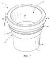
- FIG. 1is a top, perspective view of one illustrative embodiment of a decorative planter constructed in accordance with the present disclosure having a base and a collar;
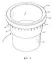
- FIG. 2is a top, perspective view of the decorative planter of FIG. 1 shown with parts separated;
- FIG. 3is a top, perspective view of the base portion showing a plurality of support struts disposed about the outer periphery thereof;
- FIG. 4is front, sectional view of the base showing a flange projecting outwardly therefrom;
- FIG. 5Ais front sectional view of the planter showing the collar engaged about the outer periphery of the base.
- FIG. 5Bis an enlarged, sectional view of the area of detail in FIG. 5A showing the collar engaged with the flange to form a decorative rim about the outer periphery of the planter.
- Planter 10includes a base 12 having a bottom portion 13 , upper and lower portions 14 and 16 , respectively, and a flange 20 disposed along the top edge of upper portion 14 .
- Planter 10also includes a selectively engageable collar 30 which engages the flange 20 such that, when assembled, the flange 20 and collar 30 form a decorative rim 40 disposed about the outer periphery of upper portion 14 of base 12 .
- base 10is generally annular in shape such that an inner periphery 18 thereof defines an annular opening 19 for receiving a plant, flower, vegetable or the like.
- other geometrical shapesare also within the scope of the present disclosure.
- flange 20has a generally inverted J-shaped cross section. More particularly, flange 20 includes a top surface 22 which projects generally radially from the upper portion 14 of base 12 and a side overhang 24 which depends downwardly from the outermost edge of top surface 22 .
- FIG. 5Bshows an enlarged view of the flange 20 and details a lip 28 which extends from side overhang 24 to define a groove 29 between the lip 28 and the flange 20 . As explained in more detail below, groove 29 engages a corresponding rib 36 which projects from collar 30 to secure the collar 30 to the base 12 .
- FIGS. 2 and 3illustrate one particular embodiment of the planter 10 which includes a plurality of support struts 26 which project outwardly from the base 12 between the overhang 24 and the flange 20 .
- support struts 26provide additional stability and strength to the decorative rim 40 when completely assembled as described below.
- collar 30is dimensioned to engage flange 20 to form decorative rim 40 disposed about the outer periphery of base 12 . More particularly, collar 30 includes an upwardly projecting rib 36 which is dimensioned to be received within groove 29 of flange 20 . Preferably, rib 36 and groove 29 engage one another in a snap-fit manner, however, it is contemplated that rib 36 and groove 29 can be engaged in a different mechanical fashion, e.g., adhesively, thermally, by synthetic hook and loop fibers which adhere when pressed together. An example of one such hook and loop fastener is commonly sold under the trademark Velcro®, locking tabs, etc.
- the collar 30includes a brace 38 which biases against the outer periphery of the upper portion 14 of the base 12 and locks the rib 36 within groove 29 .
- the upper portion 14 of base 12includes a chamfered or beveled section 17 which promotes friction-fit engagement of the brace 38 against base 12 , which, in turn, secures the rib 36 within groove 29 and prevents slippage of the collar 30 from base 12 .
- the present inventionalso relates to a method of manufacturing a planter 10 which includes the steps of:
- a collar 30dimensioned to encompass the upper portion 14 of the base 12 , the collar 30 having a mechanical interface, e.g., rib 36 , dimensioned to mechanically engage the flange 20 ;
- the collar 30can be separately molded in a variety of sophisticated and complex patterns and shapes by injection molding, extrusion, thermal molding or the like, and then attached to the base 12 during assembly of the planter 10 .
- Thiseliminates the step of rolling the upper portion 14 of the base 12 to form a decorative rim and/or eliminates subsequently forming, carving and/or cutting a decorative rim 40 in the upper portion 14 of the base 12 . It also eliminates the step of setting or securing the distal end of the collar against the base.
- At least one of the first and/or second forming stepsincludes a molding process, e.g., injection or thermal molding.
- the second step of forming the collar 30may include a molding process and the engaging step may be performed prior to the collar 30 being completely cured. It is contemplated that this may enhance the mechanical interface between the collar 30 and the base 12 .
- base 10 and collar 30are generally annular in shape
- base 12 and collar 30can be formed in other polygonal shapes depending upon a desired look or particular purpose, e.g., rectangular, oval, triangular.
- both the base 12 and the collar 30be similarly geometrically shaped so long as a portion of the collar 30 engages a portion of the base 12 in a relatively secure manner to form the decorative rim 40 .
- the outer periphery of the base 12includes a reduced diameter section 15 which highlights the transition from the upper portion 14 to the lower portion 16 and enhances the aesthetic appeal of the planter 10 .
- the collar 30can be selectively removable from the base 12 to enable a consumer to easily vary the style, appearance and/or shape of the decorative rim 40 depending upon a particular preference. For example, it is contemplated that different collars 30 having various contours, shapes and/or patterns can be easily and selectively removed and interchanged with the base 12 depending upon a particular season, holiday or consumer preference.
Landscapes
- Life Sciences & Earth Sciences (AREA)
- Environmental Sciences (AREA)
- Cultivation Receptacles Or Flower-Pots, Or Pots For Seedlings (AREA)
Abstract
Description
Claims (15)
Priority Applications (2)
| Application Number | Priority Date | Filing Date | Title |
|---|---|---|---|
| US09/567,781US6360484B1 (en) | 2000-05-09 | 2000-05-09 | Planter and method of manufacturing same |
| CA002346629ACA2346629C (en) | 2000-05-09 | 2001-05-08 | Planter and method of manufacturing same |
Applications Claiming Priority (1)
| Application Number | Priority Date | Filing Date | Title |
|---|---|---|---|
| US09/567,781US6360484B1 (en) | 2000-05-09 | 2000-05-09 | Planter and method of manufacturing same |
Publications (1)
| Publication Number | Publication Date |
|---|---|
| US6360484B1true US6360484B1 (en) | 2002-03-26 |
Family
ID=24268616
Family Applications (1)
| Application Number | Title | Priority Date | Filing Date |
|---|---|---|---|
| US09/567,781Expired - LifetimeUS6360484B1 (en) | 2000-05-09 | 2000-05-09 | Planter and method of manufacturing same |
Country Status (2)
| Country | Link |
|---|---|
| US (1) | US6360484B1 (en) |
| CA (1) | CA2346629C (en) |
Cited By (14)
| Publication number | Priority date | Publication date | Assignee | Title |
|---|---|---|---|---|
| USD483690S1 (en) | 2001-09-14 | 2003-12-16 | Gebr. Pöppelmann Kunststoffwerk-Werkzeugbau | Plant pot with faceted edge |
| US20040020111A1 (en)* | 2002-05-07 | 2004-02-05 | Ben Vandenbossche | Planter security barricade system (PSBS) |
| US20080272485A1 (en)* | 2007-05-03 | 2008-11-06 | Delphi Technologies, Inc. | Liquid cooled power electronic circuit comprising stacked direct die cooled packages |
| US7886484B1 (en)* | 2010-03-19 | 2011-02-15 | Robert Chen | Plant pot |
| US20110036000A1 (en)* | 2009-08-13 | 2011-02-17 | Carl Verdecia | Invertible Embedded Container System |
| US20110056130A1 (en)* | 2009-09-09 | 2011-03-10 | Jun Wang | Flower pot with double revers |
| US20110232187A1 (en)* | 2010-03-24 | 2011-09-29 | Quan Theresa Z | Nursery container |
| US20120279123A1 (en)* | 2011-05-05 | 2012-11-08 | Pride Garden Products | Decorative container |
| US20130133252A1 (en)* | 2011-05-24 | 2013-05-30 | Kenneth A. Harbaugh | Planter with snap-in rim insert |
| US8667735B2 (en) | 2010-08-30 | 2014-03-11 | Att Southern, Inc. | Molded planter with wide upper rim |
| US20160374274A1 (en)* | 2015-06-24 | 2016-12-29 | Ron Tyler Johnson | Apparatus and method for growing plants |
| US20170086385A1 (en)* | 2015-09-26 | 2017-03-30 | Donald Eugene Harris, Sr. | Bottomless In-Ground Water Conservation and Contamination Prevention Garden-Plant Watering-Well |
| US20170086387A1 (en)* | 2015-09-26 | 2017-03-30 | Donald Eugene Harris, Sr. | Bottomless In-Ground Garden-Plant Watering-Well with Removable Twist-Ring |
| USD995241S1 (en) | 2019-04-30 | 2023-08-15 | Colleen Marcella Talbert | Hillside planter dam |
Families Citing this family (2)
| Publication number | Priority date | Publication date | Assignee | Title |
|---|---|---|---|---|
| WO2025114942A1 (en)* | 2023-11-29 | 2025-06-05 | Kuma Ii B.V. | Plastic pot |
| NL2037182B1 (en)* | 2024-03-05 | 2025-09-15 | Kuma Ii B V | PLASTIC POT |
Citations (32)
| Publication number | Priority date | Publication date | Assignee | Title |
|---|---|---|---|---|
| US1557712A (en) | 1924-07-19 | 1925-10-20 | Wilber R Little | Flowerpot |
| US1778150A (en) | 1927-12-15 | 1930-10-14 | Freeburg Sture | Flowerpot |
| US2738621A (en) | 1950-06-12 | 1956-03-20 | Hermann R Abbrecht | Flower pot |
| US2785508A (en)* | 1954-06-22 | 1957-03-19 | Jr William R Coleman | Flower pot collar plant protector |
| US2790269A (en) | 1954-08-09 | 1957-04-30 | Jr William R Coleman | Flower pot collar plant protector |
| US3079037A (en) | 1960-06-27 | 1963-02-26 | Phillips Petroleum Co | Container provided with cover seal and tray-closure |
| US3415011A (en) | 1966-03-11 | 1968-12-10 | Beloit Corp | Flanged plant container |
| US3704545A (en)* | 1970-04-21 | 1972-12-05 | George Van Zonneveld | Plastic container for bulbous plants |
| US3961443A (en)* | 1975-05-05 | 1976-06-08 | Insalaco Charles J | Cover for nursery pots providing improved protection, support and feeding |
| US4070794A (en) | 1976-08-09 | 1978-01-31 | Gibbs Geraldine L | Plant water trough |
| DE2725446A1 (en)* | 1977-06-04 | 1978-12-21 | Hoechst Ag | Foam thermoplastic cup for drinks machines - preform has top bellows part which is ultrasonically welded into lip |
| US4145841A (en)* | 1976-11-05 | 1979-03-27 | Woolpert John C | Extendable planter |
| US4369598A (en)* | 1981-03-19 | 1983-01-25 | Beckwith Thomas F | Container element combination for seed sprouting or plant culture |
| US4706833A (en)* | 1986-09-22 | 1987-11-17 | Shell Oil Company | Thermoplastic container |
| US4791754A (en)* | 1987-07-13 | 1988-12-20 | Demars Jr George H | Plant assisting device |
| US4835834A (en) | 1986-06-20 | 1989-06-06 | Highland Supply Corporation | Method of shaping and holding a sheet of material about a flower pot with a collar |
| US4901423A (en) | 1988-08-11 | 1990-02-20 | Highland Supply Corporation | Method of shaping and holding a sheet of material about a flower pot with a collar |
| US4980209A (en)* | 1989-05-09 | 1990-12-25 | Aec Machinery Limited | Wrap for a flower pot |
| US4995192A (en)* | 1989-11-27 | 1991-02-26 | Dewid Richard | Soil cover for potted or in-ground plants |
| US5077937A (en) | 1986-06-20 | 1992-01-07 | Highland Supply Corporation | Apparatus for providing a decorative cover for a flower pot using a collar |
| US5105599A (en) | 1989-02-24 | 1992-04-21 | Highland Supply Corporation | Means for securing a decorative cover about a flower pot |
| US5184390A (en) | 1986-06-20 | 1993-02-09 | Highland Supply Corporation | Method of shaping and holding a sheet of material about a flower pot with a collar |
| US5353546A (en) | 1993-06-23 | 1994-10-11 | Bock Ronald F | Combination vase and air fragrance dispenser |
| US5477640A (en) | 1994-12-01 | 1995-12-26 | International Plant Breeding Ag | Fragrance emitting plant watering system |
| US5535548A (en) | 1986-06-20 | 1996-07-16 | The Family Trust U/T/A | Apparatus for providing a decorative cover for a flower pot using a collar |
| US5551140A (en) | 1984-05-22 | 1996-09-03 | Southpac Trust International, Inc. | Method of covering a flower pot with a pot cover having an elastic fastener incorporated therein |
| US5566439A (en) | 1988-09-26 | 1996-10-22 | Southpac Trust International, Inc. | Method for forming a decorative cover |
| US5782453A (en) | 1996-12-13 | 1998-07-21 | Tuzza; Lou Ann | Decorative tree planter stand |
| GB2349790A (en)* | 1999-03-16 | 2000-11-15 | Colin Peter Wanley | Varying height plant growing assembly |
| US6161332A (en)* | 1996-10-07 | 2000-12-19 | Avot Beheer B.V. | Protective container for a potlike or boxlike container |
| US6170144B1 (en)* | 1995-08-09 | 2001-01-09 | Enviroworks, Inc. | Method of making a decorative container |
| EP1110870A1 (en)* | 1999-12-15 | 2001-06-27 | Riviera | Pot with a single wall and with a strengthened holding rim |
- 2000
- 2000-05-09USUS09/567,781patent/US6360484B1/ennot_activeExpired - Lifetime
- 2001
- 2001-05-08CACA002346629Apatent/CA2346629C/ennot_activeExpired - Fee Related
Patent Citations (35)
| Publication number | Priority date | Publication date | Assignee | Title |
|---|---|---|---|---|
| US1557712A (en) | 1924-07-19 | 1925-10-20 | Wilber R Little | Flowerpot |
| US1778150A (en) | 1927-12-15 | 1930-10-14 | Freeburg Sture | Flowerpot |
| US2738621A (en) | 1950-06-12 | 1956-03-20 | Hermann R Abbrecht | Flower pot |
| US2785508A (en)* | 1954-06-22 | 1957-03-19 | Jr William R Coleman | Flower pot collar plant protector |
| US2790269A (en) | 1954-08-09 | 1957-04-30 | Jr William R Coleman | Flower pot collar plant protector |
| US3079037A (en) | 1960-06-27 | 1963-02-26 | Phillips Petroleum Co | Container provided with cover seal and tray-closure |
| US3415011A (en) | 1966-03-11 | 1968-12-10 | Beloit Corp | Flanged plant container |
| US3704545A (en)* | 1970-04-21 | 1972-12-05 | George Van Zonneveld | Plastic container for bulbous plants |
| US3961443A (en)* | 1975-05-05 | 1976-06-08 | Insalaco Charles J | Cover for nursery pots providing improved protection, support and feeding |
| US4070794A (en) | 1976-08-09 | 1978-01-31 | Gibbs Geraldine L | Plant water trough |
| US4145841A (en)* | 1976-11-05 | 1979-03-27 | Woolpert John C | Extendable planter |
| DE2725446A1 (en)* | 1977-06-04 | 1978-12-21 | Hoechst Ag | Foam thermoplastic cup for drinks machines - preform has top bellows part which is ultrasonically welded into lip |
| US4369598A (en)* | 1981-03-19 | 1983-01-25 | Beckwith Thomas F | Container element combination for seed sprouting or plant culture |
| US5781981A (en) | 1984-05-22 | 1998-07-21 | Southpac Trust International, Inc. | Method of covering a flower pot with a pot cover having an elastic fastener incorporated therein |
| US5551140A (en) | 1984-05-22 | 1996-09-03 | Southpac Trust International, Inc. | Method of covering a flower pot with a pot cover having an elastic fastener incorporated therein |
| US4835834A (en) | 1986-06-20 | 1989-06-06 | Highland Supply Corporation | Method of shaping and holding a sheet of material about a flower pot with a collar |
| US5535548A (en) | 1986-06-20 | 1996-07-16 | The Family Trust U/T/A | Apparatus for providing a decorative cover for a flower pot using a collar |
| US5561894A (en) | 1986-06-20 | 1996-10-08 | Southpac Trust International, Inc. | Method for providing a decorative cover for a flower pot using a collar |
| US5077937A (en) | 1986-06-20 | 1992-01-07 | Highland Supply Corporation | Apparatus for providing a decorative cover for a flower pot using a collar |
| US5184390A (en) | 1986-06-20 | 1993-02-09 | Highland Supply Corporation | Method of shaping and holding a sheet of material about a flower pot with a collar |
| US5274900A (en) | 1986-06-20 | 1994-01-04 | Highland Supply Corporation | Method of shaping and holding a sheet of material about a flower pot with a collar |
| US4706833A (en)* | 1986-09-22 | 1987-11-17 | Shell Oil Company | Thermoplastic container |
| US4791754A (en)* | 1987-07-13 | 1988-12-20 | Demars Jr George H | Plant assisting device |
| US4901423A (en) | 1988-08-11 | 1990-02-20 | Highland Supply Corporation | Method of shaping and holding a sheet of material about a flower pot with a collar |
| US5566439A (en) | 1988-09-26 | 1996-10-22 | Southpac Trust International, Inc. | Method for forming a decorative cover |
| US5105599A (en) | 1989-02-24 | 1992-04-21 | Highland Supply Corporation | Means for securing a decorative cover about a flower pot |
| US4980209A (en)* | 1989-05-09 | 1990-12-25 | Aec Machinery Limited | Wrap for a flower pot |
| US4995192A (en)* | 1989-11-27 | 1991-02-26 | Dewid Richard | Soil cover for potted or in-ground plants |
| US5353546A (en) | 1993-06-23 | 1994-10-11 | Bock Ronald F | Combination vase and air fragrance dispenser |
| US5477640A (en) | 1994-12-01 | 1995-12-26 | International Plant Breeding Ag | Fragrance emitting plant watering system |
| US6170144B1 (en)* | 1995-08-09 | 2001-01-09 | Enviroworks, Inc. | Method of making a decorative container |
| US6161332A (en)* | 1996-10-07 | 2000-12-19 | Avot Beheer B.V. | Protective container for a potlike or boxlike container |
| US5782453A (en) | 1996-12-13 | 1998-07-21 | Tuzza; Lou Ann | Decorative tree planter stand |
| GB2349790A (en)* | 1999-03-16 | 2000-11-15 | Colin Peter Wanley | Varying height plant growing assembly |
| EP1110870A1 (en)* | 1999-12-15 | 2001-06-27 | Riviera | Pot with a single wall and with a strengthened holding rim |
Cited By (20)
| Publication number | Priority date | Publication date | Assignee | Title |
|---|---|---|---|---|
| USD483690S1 (en) | 2001-09-14 | 2003-12-16 | Gebr. Pöppelmann Kunststoffwerk-Werkzeugbau | Plant pot with faceted edge |
| US20040020111A1 (en)* | 2002-05-07 | 2004-02-05 | Ben Vandenbossche | Planter security barricade system (PSBS) |
| US20080272485A1 (en)* | 2007-05-03 | 2008-11-06 | Delphi Technologies, Inc. | Liquid cooled power electronic circuit comprising stacked direct die cooled packages |
| US20110036000A1 (en)* | 2009-08-13 | 2011-02-17 | Carl Verdecia | Invertible Embedded Container System |
| US20110056130A1 (en)* | 2009-09-09 | 2011-03-10 | Jun Wang | Flower pot with double revers |
| US7886484B1 (en)* | 2010-03-19 | 2011-02-15 | Robert Chen | Plant pot |
| US20110232187A1 (en)* | 2010-03-24 | 2011-09-29 | Quan Theresa Z | Nursery container |
| US9226455B2 (en) | 2010-08-30 | 2016-01-05 | Att Southern Inc. | Molded planter with wide upper rim |
| US8667735B2 (en) | 2010-08-30 | 2014-03-11 | Att Southern, Inc. | Molded planter with wide upper rim |
| US10219444B2 (en) | 2010-08-30 | 2019-03-05 | Att Southern, Inc. | Molded planter with wide upper rim |
| US20190141907A1 (en)* | 2010-08-30 | 2019-05-16 | Att Southern, Inc. | Molded planter with wide upper rim |
| US20120279123A1 (en)* | 2011-05-05 | 2012-11-08 | Pride Garden Products | Decorative container |
| US20130133252A1 (en)* | 2011-05-24 | 2013-05-30 | Kenneth A. Harbaugh | Planter with snap-in rim insert |
| US9237692B2 (en)* | 2011-05-24 | 2016-01-19 | Att Southern Inc. | Planter with snap-in rim insert |
| US20160374274A1 (en)* | 2015-06-24 | 2016-12-29 | Ron Tyler Johnson | Apparatus and method for growing plants |
| US20170086385A1 (en)* | 2015-09-26 | 2017-03-30 | Donald Eugene Harris, Sr. | Bottomless In-Ground Water Conservation and Contamination Prevention Garden-Plant Watering-Well |
| US20170086387A1 (en)* | 2015-09-26 | 2017-03-30 | Donald Eugene Harris, Sr. | Bottomless In-Ground Garden-Plant Watering-Well with Removable Twist-Ring |
| US10123490B2 (en)* | 2015-09-26 | 2018-11-13 | Donald Eugene Harris, Sr. | Bottomless in-ground water conservation and contamination prevention garden-plant watering-well |
| US10314247B2 (en)* | 2015-09-26 | 2019-06-11 | Donald Eugene Harris, Sr. | Bottomless in-ground garden-plant watering-well with removable twist-ring |
| USD995241S1 (en) | 2019-04-30 | 2023-08-15 | Colleen Marcella Talbert | Hillside planter dam |
Also Published As
| Publication number | Publication date |
|---|---|
| CA2346629C (en) | 2006-11-21 |
| CA2346629A1 (en) | 2001-11-09 |
Similar Documents
| Publication | Publication Date | Title |
|---|---|---|
| US6360484B1 (en) | Planter and method of manufacturing same | |
| US5094032A (en) | Pot having root anchors | |
| US5711106A (en) | Landscape edging product | |
| KR20080048064A (en) | Containers for planting plants or plants and planar deployments thereof | |
| US4133922A (en) | Wreath device | |
| ZA200603222B (en) | Method of making a decorative arrangement | |
| US20070113473A1 (en) | Circular retaining device for landscaping | |
| US20080271370A1 (en) | Planter | |
| KR101558845B1 (en) | A planter of the method | |
| KR101140073B1 (en) | Flowerpot with disposable cups | |
| JP4701317B1 (en) | Rocky planting tools | |
| KR100463884B1 (en) | An element for accessary and manufacturing method therefor | |
| US20020059750A1 (en) | Flowerpot and flowerpot / support stick assembly | |
| KR102331272B1 (en) | Mushroom growth guide receptacle | |
| US20070006527A1 (en) | Flowerpot for growing flower | |
| US20250098878A1 (en) | Reinforced flowerpot cover | |
| KR950005161Y1 (en) | Device for decoration of flower-pots | |
| KR200317055Y1 (en) | Plate for a potted plant | |
| KR200174616Y1 (en) | A flowerpot | |
| KR200307387Y1 (en) | An element for accessary | |
| JP4784799B2 (en) | flower pot | |
| JPH0139168Y2 (en) | ||
| CA2449374A1 (en) | Production of flower pots | |
| US6482480B1 (en) | Ornamental accessory and method of making same | |
| KR200183627Y1 (en) | Flowerpot for road ornament |
Legal Events
| Date | Code | Title | Description |
|---|---|---|---|
| AS | Assignment | Owner name:DYNAMIC DESIGN, INC., NEW YORK Free format text:ASSIGNMENT OF ASSIGNORS INTEREST;ASSIGNOR:KREIZEL, JAMES;REEL/FRAME:010812/0685 Effective date:20000504 | |
| STCF | Information on status: patent grant | Free format text:PATENTED CASE | |
| AS | Assignment | Owner name:NATIONAL SALES COMPANY, LLC D/B/A DYNAMIC DESIGN, Free format text:ASSIGNMENT OF ASSIGNORS INTEREST;ASSIGNOR:DYNAMIC DESIGN, INC.;REEL/FRAME:013417/0675 Effective date:20021008 | |
| AS | Assignment | Owner name:AMES PLANTER, INC., PENNSYLVANIA Free format text:ASSIGNMENT OF ASSIGNORS INTEREST;ASSIGNOR:NATIONAL SALES COMPANY LLC D/B/A DYNAMIC DESIGN;REEL/FRAME:013570/0401 Effective date:20021115 Owner name:FOOTHILL CAPITAL CORPORATION, CALIFORNIA Free format text:SECURITY AGREEMENT;ASSIGNOR:AMES PLANTER, INC.;REEL/FRAME:013570/0404 Effective date:20021115 | |
| AS | Assignment | Owner name:WELLS FARGO FOOTHILL, INC., AS AGENT, MASSACHUSETT Free format text:AMENDMENT NO. 1 TO PATENT SECURITY AGREEMENT;ASSIGNOR:AMES TRUE TEMPER PROPERTIES, INC., A MICHIGAN CORPORATION;REEL/FRAME:014560/0252 Effective date:20030804 Owner name:AMES TRUE TEMPER, INC., A DELAWARE CORPORATION, PE Free format text:AMENDMENT NO. 1 TO PATENT SECURITY AGREEMENT;ASSIGNOR:AMES TRUE TEMPER PROPERTIES, INC., A MICHIGAN CORPORATION;REEL/FRAME:014560/0252 Effective date:20030804 | |
| AS | Assignment | Owner name:AMES TRUE TEMPER, INC., PENNSYLVANIA Free format text:MERGER;ASSIGNOR:AMES PLANTER, INC.;REEL/FRAME:014734/0745 Effective date:20030928 | |
| FEPP | Fee payment procedure | Free format text:PAYOR NUMBER ASSIGNED (ORIGINAL EVENT CODE: ASPN); ENTITY STATUS OF PATENT OWNER: LARGE ENTITY | |
| FEPP | Fee payment procedure | Free format text:PAT HOLDER NO LONGER CLAIMS SMALL ENTITY STATUS, ENTITY STATUS SET TO UNDISCOUNTED (ORIGINAL EVENT CODE: STOL); ENTITY STATUS OF PATENT OWNER: LARGE ENTITY | |
| FPAY | Fee payment | Year of fee payment:4 | |
| AS | Assignment | Owner name:AMES TRUE TEMPER, INC., PENNSYLVANIA Free format text:RELEASE OF SECURITY INTEREST IN PATENTS AND TRADEMARKS;ASSIGNOR:WELLS FARGO FOOTHILL, INC.;REEL/FRAME:016470/0669 Effective date:20040625 Owner name:IXL MANUFACTURING COMPANY, INC., PENNSYLVANIA Free format text:RELEASE OF SECURITY INTEREST IN PATENTS AND TRADEMARKS;ASSIGNOR:WELLS FARGO FOOTHILL, INC.;REEL/FRAME:016470/0669 Effective date:20040625 Owner name:AMES TRUE TEMPER PROPERTIES, INC., PENNSYLVANIA Free format text:RELEASE OF SECURITY INTEREST IN PATENTS AND TRADEMARKS;ASSIGNOR:WELLS FARGO FOOTHILL, INC.;REEL/FRAME:016470/0669 Effective date:20040625 Owner name:AMES PLANTER, INC., PENNSYLVANIA Free format text:RELEASE OF SECURITY INTEREST IN PATENTS AND TRADEMARKS;ASSIGNOR:WELLS FARGO FOOTHILL, INC.;REEL/FRAME:016470/0669 Effective date:20040625 | |
| AS | Assignment | Owner name:AMES PLANTER, INC., PENNSYLVANIA Free format text:RELEASE OF SECURITY INTEREST;ASSIGNOR:WELLS FARGO FOOTHILL, INC. (N/K/A WELLS FARGO FOOTHILL, INC.);REEL/FRAME:016489/0801 Effective date:20040625 Owner name:IXL MANUFACTURING COMPANY, INC., PENNSYLVANIA Free format text:RELEASE OF SECURITY INTEREST;ASSIGNOR:WELLS FARGO FOOTHILL, INC. (N/K/A WELLS FARGO FOOTHILL, INC.);REEL/FRAME:016489/0801 Effective date:20040625 Owner name:AMES TRUE TEMPER PROPERTIES, INC., PENNSYLVANIA Free format text:RELEASE OF SECURITY INTEREST;ASSIGNOR:WELLS FARGO FOOTHILL, INC. (N/K/A WELLS FARGO FOOTHILL, INC.);REEL/FRAME:016489/0801 Effective date:20040625 Owner name:AMES TRUE TEMPER, PENNSYLVANIA Free format text:RELEASE OF SECURITY INTEREST;ASSIGNOR:WELLS FARGO FOOTHILL, INC. (N/K/A WELLS FARGO FOOTHILL, INC.);REEL/FRAME:016489/0801 Effective date:20040625 | |
| AS | Assignment | Owner name:BANK OF AMERICA, N.A., NORTH CAROLINA Free format text:SECURITY INTEREST;ASSIGNORS:AMES TRUE TEMPER, INC.;ATT HOLDING CO.;AMES TRUE TEMPER PROPERTIES, INC.;REEL/FRAME:017006/0935 Effective date:20040628 | |
| FPAY | Fee payment | Year of fee payment:8 | |
| AS | Assignment | Owner name:JPMORGAN CHASE BANK, N.A., AS ADMINISTRATIVE AGENT Free format text:AMENDED AND RESTATED GRANT OF SECURITY INTEREST IN PATENT RIGHTS;ASSIGNOR:AMES TRUE TEMPER, INC.;REEL/FRAME:025126/0506 Effective date:20100930 | |
| AS | Assignment | Owner name:GOLDMAN SACHS LENDING PARTNERS, LLC AS COLLATERAL Free format text:SECURITY AGREEMENT;ASSIGNORS:CLOPAY BUILDING PRODUCTS COMPANY, INC.;CLOPAY PLASTIC PRODUCTS COMPANY, INC.;AMES TRUE TEMPER, INC.;REEL/FRAME:025324/0757 Effective date:20100930 | |
| AS | Assignment | Owner name:AMES TRUE TEMPER PROPERTIES,INC., PENNSYLVANIA Free format text:RELEASE BY SECURED PARTY;ASSIGNOR:BANK OF AMERICA N.A., AS ADMINISTRATIVE AGENT;REEL/FRAME:025406/0624 Effective date:20100930 Owner name:AMES TRUE TEMPER, INC., PENNSYLVANIA Free format text:RELEASE BY SECURED PARTY;ASSIGNOR:BANK OF AMERICA N.A., AS ADMINISTRATIVE AGENT;REEL/FRAME:025406/0624 Effective date:20100930 Owner name:ATT HOLDING COMPANY, PENNSYLVANIA Free format text:RELEASE BY SECURED PARTY;ASSIGNOR:BANK OF AMERICA N.A., AS ADMINISTRATIVE AGENT;REEL/FRAME:025406/0624 Effective date:20100930 | |
| AS | Assignment | Owner name:AMES TRUE TEMPER, INC., PENNSYLVANIA Free format text:RELEASE BY SECURED PARTY;ASSIGNOR:GOLDMAN SACHS LENDING PARTNERS LLC;REEL/FRAME:025990/0749 Effective date:20110317 | |
| AS | Assignment | Owner name:AMES TRUE TEMPER, INC., OHIO Free format text:TERMINATION AND RELEASE OF SECURITY INTEREST IN PATENT RIGHTS;ASSIGNOR:JPMORGAN CHASE BANK, N.A., AS ADMINISTRATIVE AGENT;REEL/FRAME:026159/0253 Effective date:20110318 | |
| AS | Assignment | Owner name:JPMORGAN CHASE BANK, N.A., AS ADMINISTRATIVE AGENT Free format text:SECURITY AGREEMENT;ASSIGNOR:AMES TRUE TEMPER, INC.;REEL/FRAME:026163/0645 Effective date:20110318 Owner name:JPMORGAN CHASE BANK, N.A., AS ADMINISTRATIVE AGENT, TEXAS Free format text:SECURITY AGREEMENT;ASSIGNOR:AMES TRUE TEMPER, INC.;REEL/FRAME:026163/0645 Effective date:20110318 | |
| FPAY | Fee payment | Year of fee payment:12 | |
| AS | Assignment | Owner name:THE AMES COMPANIES, INC., PENNSYLVANIA Free format text:CHANGE OF NAME;ASSIGNOR:AMES TRUE TEMPER, INC.;REEL/FRAME:032982/0963 Effective date:20140428 | |
| FEPP | Fee payment procedure | Free format text:PAYER NUMBER DE-ASSIGNED (ORIGINAL EVENT CODE: RMPN); ENTITY STATUS OF PATENT OWNER: LARGE ENTITY Free format text:PAYOR NUMBER ASSIGNED (ORIGINAL EVENT CODE: ASPN); ENTITY STATUS OF PATENT OWNER: LARGE ENTITY | |
| AS | Assignment | Owner name:BANK OF AMERICA, N.A., NORTH CAROLINA Free format text:NOTICE OF SUCCESSION OF AGENCY;ASSIGNOR:JPMORGAN CHASE BANK, N.A.;REEL/FRAME:048433/0051 Effective date:20190222 |