US6360115B1 - System for imaging mechanically stabilized tissue - Google Patents
System for imaging mechanically stabilized tissueDownload PDFInfo
- Publication number
- US6360115B1 US6360115B1US09/397,329US39732999AUS6360115B1US 6360115 B1US6360115 B1US 6360115B1US 39732999 AUS39732999 AUS 39732999AUS 6360115 B1US6360115 B1US 6360115B1
- Authority
- US
- United States
- Prior art keywords
- tissue
- clamping
- imaging system
- imaging
- clamped
- Prior art date
- Legal status (The legal status is an assumption and is not a legal conclusion. Google has not performed a legal analysis and makes no representation as to the accuracy of the status listed.)
- Expired - Lifetime
Links
Images


Classifications
- G—PHYSICS
- G02—OPTICS
- G02B—OPTICAL ELEMENTS, SYSTEMS OR APPARATUS
- G02B21/00—Microscopes
- G02B21/0004—Microscopes specially adapted for specific applications
- G02B21/0012—Surgical microscopes
- G—PHYSICS
- G02—OPTICS
- G02B—OPTICAL ELEMENTS, SYSTEMS OR APPARATUS
- G02B21/00—Microscopes
- G02B21/34—Microscope slides, e.g. mounting specimens on microscope slides
- A—HUMAN NECESSITIES
- A61—MEDICAL OR VETERINARY SCIENCE; HYGIENE
- A61B—DIAGNOSIS; SURGERY; IDENTIFICATION
- A61B10/00—Instruments for taking body samples for diagnostic purposes; Other methods or instruments for diagnosis, e.g. for vaccination diagnosis, sex determination or ovulation-period determination; Throat striking implements
- A61B10/02—Instruments for taking cell samples or for biopsy
- A61B10/0233—Pointed or sharp biopsy instruments
Definitions
- the present inventionrelates to an imaging system for in vivo examinations of tissues, and particularly to a confocal imaging system operative upon the tissue of a patient body part or animal subject which mechanically stabilizes the tissue to minimize instability in confocal images of the tissue.
- This inventionis especially suitable for providing an instrument or attachment for pathological applications.
- confocal images from such systemsmay appear unstable to the viewing physician, making it difficult for the physician to observe dermal structures of interest. Even slight motion of the patient's skin tissue, such as due to involuntary muscle movement in adjacent tissue or from a circulatory pulse, can cause dermal structures of a confocal image to appear to move in and out of the imaged tissue area.
- the confocal opticsmay also image other types of patient tissue in addition to dermal tissues, for example, oral tissue of the tongue or lip, but motion of such tissue can still cause instability in confocal images of tissue structures.
- the present inventionembodies a system having a clamping apparatus with first and second members, which are spaced apart from each other.
- An attachment mechanismis connected to the first member for attaching the apparatus to a confocal imaging system.
- the attachment mechanismhas a surface facing the tissue to be examined. Opposing this surface is a third member which is connected to the second member.
- a clamping mechanismincludes the first and second members for clamping the tissue between the surface of the attachment mechanism and the surface of the third member.
- a windowis provided in the surface of the attachment mechanism for presenting the clamped tissue to the confocal imaging system.
- the clamping mechanismmay include a turn screw threaded through the first and second members, or a pneumatic system, for clamping the apparatus to the tissue.
- An optional suction mechanismmay be used to assist in clamping the tissue to the attachment mechanism.
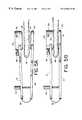
- FIG. 1is a side elevational view of the system of the present invention showing a clamping apparatus attached to a confocal imaging system;
- FIG. 2is a top view of the clamping apparatus of FIG. 1;
- FIG. 3is a perspective view from the bottom of the clamping apparatus of FIGS. 1 and 2;
- FIG. 4is a perspective view from the top of the clamping apparatus of FIGS. 1 and 2;
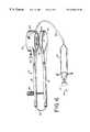
- FIGS. 5A and 5Bare side views of the clamping apparatus of FIG. 1 showing an example of the apparatus before and after being clamped to tissue, respectively;
- FIG. 6is a perspective view from the bottom of the clamping apparatus of FIGS. 1 and 2 showing an optional suction mechanism to assist in clamping tissue;
- FIGS. 7A and 7Bare side views of the clamping apparatus similar to FIG. 1 showing a clamping mechanism with a pneumatic system before and after the bladder of the pneumatic system is inflated, respectively, to clamp the apparatus to tissue;
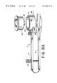
- FIGS. 8A, 8 B and 8 Care perspective views from the top of the clamping apparatus of FIG. 5B showing a biopsy device before, during and after taking a biopsy of the clamped tissue through the apparatus, respectively.
- a system 8includes a clamping apparatus 10 having a first member 12 and a second member 14 which is spaced apart from the first member.
- Member 12has a lower surface 16 opposing an upper surface 18 of member 14 .
- a mechanism 20 for attaching or coupling apparatus 10 to a confocal imaging system 22 of system 8At one end of member 12 is connected a mechanism 20 for attaching or coupling apparatus 10 to a confocal imaging system 22 of system 8 .
- confocal imaging system 22is represented by a cylinder 23 which contains confocal optics, such as an objective focusing lens. Confocal imaging system 22 is described in related U.S. application Ser. No. 08/683,607, filed on Jul. 15, 1996.
- system 22may also represent a system using other imaging modalities, such as optical coherence tomography, described for example in Schmitt et al., “Optical characterization of disease tissues using low-coherence interferometry,” Proc. of SPIE, Volume 1889 (1993), or two-photon microscopy, described for example in U.S. Pat. No. 5,034,613, to Denk et al., or deconvolution confocal microscopy, described for example in Kesterson, et al., “Confocal Microscope Capability with Desktop Affordability,” Advanced Images, Oct. 1991, pages 23-24, or fluorescent imaging.
- the objective focusing lens in system 22may be part of a fixed station or a portable confocal imaging system providing images of the tissue which are microscopic for pathological examination.
- Mechanism 20has an annular receptacle 24 , such as a ring, having a lower member or template 28 .
- Receptacle 24receives cylinder 23 , while pins 26 , for example three, are threaded into the sides of receptacle 24 , such that they can be extended into grooves or openings 27 in cylinder 23 , thereby fixing the position of the confocal imaging system 22 to apparatus 10 .
- Openings 27 and cylinder 23are shown in receptacle 24 of FIG. 1 as dashed lines.
- Mechanism 20is described, for example, in related Application No. 08/683,607, filed Jul. 15, 1996.
- Template 28has an aperture 30 through which the confocal imaging system, i.e., confocal optics, images the tissue.
- Aperture 30may, for example, be several millimeters in diameter.
- an annular recess 34 in the bottom surface 29 of template 28is in communication with aperture 30 , in other words, a bore of smaller to larger diameter from aperture 30 and recess 34 , respectively, widens to provide an annular recess 34 at surface 29 .
- a window 32 of a thin transparent material, such as plastic or glassis fitted in recess 34 .
- window 32may be a thin plate of glass, suitably about 0.1-0.2 mm thick.
- Window 32is sized such that it fits into annular recess 34 , however, window 32 may be square in shape, thus requiring grooves in recess 34 to receive the corners of the window.
- Window 32for example, may be a coverslip as conventionally used in preparation of slides for a typical optical microscope.
- Surface 29 of template 28has a textured surface, which is represented by raised ridges 36 .
- an opposing member 40has an upper surface 41 which opposes surface 29 of mechanism 20 .
- Opposing member 40is connected to an end 14 b of member 14 .
- Upper surface 41has a textured surface, which is represented by raised ridges 38 (see FIG. 4 ).
- Surface 41optionally may have a layer of deformable compliant material, such as urethane.
- Member 40may be a disk, as illustrated in the figures, however the shape of member 40 may depend on the patient body part having the tissue to be located between surfaces 29 and 41 .
- member 40may be split into two or more sections, like a fork, to avoid interfering with other tissue near the body part, such as when the tissue to be imaged is in the middle of the tongue.
- member 40may be any structure providing a surface 41 which opposes surface 29 and can provide pressure and traction against a patient body part clamped between surfaces 29 and 41 , as described below.
- Members 12 and 14 , receptacle 24 , and member 40may be made of stainless-steel or plastic.
- Receptacle 24may be a separate component that is joined (screwed or welded) to the assembly of member 12 .
- a clamping mechanism in apparatus 10clamps tissue in the space between surface 29 of mechanism 20 and surface 41 of member 40 .
- the clamping mechanismincludes a hinge provided by a spring 42 to members 12 and 14 at the ends thereof opposite mechanism 20 and member 40 , respectively, a turn screw 44 threaded in holes 12 a and 14 a through members 12 and 14 , respectively, and members 12 and 14 connected to mechanism 20 and member 40 , respectively.
- Spring 42is a flat strip of flexible material (steel, plastic or bronze), and applies a force on members 12 and 14 pushing the members apart from each other.
- Screw 44is rotatable to manually adjust the spacing between surfaces 29 and 41 , such that tissue can be clamped between surfaces 29 and 41 , and released therefrom.
- the clamping mechanismmay be provided by two or more screws, similar to screw 44 , threaded through members 12 and 14 for setting the space between surfaces 29 and 41 . These screws can be independently adjusted to provide angular adjustment of members 12 and 14 to each other to insure that surfaces 29 and 41 are parallel as they restrain the tissue. Other means for clamping may also be used which are similar to clamps of conventional surgical instruments.
- a tongue 46 having the tissue of a patient to be examinedis first inserted between members 12 and 14 .
- an operatorturns screw 44 until the space between surfaces 29 and 41 is wider than the thickness of the tongue.
- the tongueis clamped to apparatus 10 by the operator turning screw 44 until the tongue is immobilized with respect to surfaces 29 and 41 without damaging the tissue or causing unnecessary discomfort to the patient.
- the textured surfaces of surfaces 29 and 41provide traction against the surfaces of tongue 46 to maintain the tissue area under investigation stable for imaging.
- the confocal imaging system 22is attached into receptacle 24 of mechanism 20 using pins 26 , as shown in FIG. 1, to provide an integrated assembly of the imaging system 22 and apparatus 10 .
- the attachmentmay be done most conveniently after the tissue is clamped by apparatus 10 , however it may occur before tongue 46 is clamped.
- Window 32 in surface 29 of mechanism 20presents a tissue area of the clamped tongue to the confocal imaging optics in system 22 , thereby enabling confocal imaging of the tissue beneath the window.
- the tissue under the windowis thus mechanical stabilized to the confocal imaging system 22 , which minimize instability in confocal images by reducing the relative motion of tissue with respect to the confocal imaging optics of system 22 .
- Apparatus 10may also operate without window 32 , such that window 32 is removed from recess 34 prior to apparatus 10 being clamped to tissue.
- a suction mechanismmay assist in clamping apparatus 10 to tongue 46 , as shown in FIG. 6 .
- the suction mechanismincludes a syringe 50 connected through a hose 52 to receptacle 24 .
- An annular opening, or one or more holes, provided in surface 29 of receptacle 24is in communication with hose 52 , such that after apparatus 10 is clamped to tongue 46 , pulling plunger 51 of syringe 50 in the direction of arrow 53 suctions any air between surface 29 and the surface of tongue 46 facing surface 29 . This results in a vacuum adhering surface 29 and the clamped tissue together, thereby further stabilizing the tongue against window 32 .
- clamping apparatus 10is shown in which the clamping mechanism is provided by a pneumatic system instead of turn screw 44 (FIG. 1 ), and members 12 and 14 are part of a single C-shaped member 13 without hinge 42 .
- the pneumatic systemincludes a bladder 54 , which is attached to surface 41 , a syringe 58 , and a hose 56 connecting syringe 58 to bladder 54 .
- a fluid 57such as air, water, or the like, can pass through hose 56 between bladder 54 and a cavity 60 in syringe 58 .
- Cavity 60is defined by the interior of syringe 58 and the head 63 of a plunger 62 in syringe 58 .
- Plunger 62is slidable within syringe 58 to change the volume of fluid 57 in both cavity 60 and bladder 54 .
- bladder 54is deflated due to the lack of fluid 57 in bladder 54 .
- the tissuesuch as tongue 46 of FIG. 5A
- plunger 62is pushed by an operator to a second position, as shown in FIG. 7 B.
- Bladder 54is inflated to sufficiently clamp apparatus 10 to the tissue.
- Hose 56may be clamped if needed to prevent back flow of fluid 57 into cavity 60 of syringe 58 .
- single or multiple turn screws 44may be used in apparatus 10 in combination with the pneumatic system in which bladder 54 , when inflated, provides an additional clamping force upon the tissue.
- System 8is particularly useful for mechanically stabilizing the confocal imaging system 22 to oral tissue, such as the tongue or lip, which may have mucus on its surface.
- apparatus 10may be sized to accommodate clamping of other tissues of the patient to mechanism 20 , such as fingers, the palm of a hand, nails, ears, or male genitalia.
- the tissueis released from apparatus 10 by turning turn screw 44 (FIG. 1) in a direction which moves member 40 and mechanism 20 apart from each other, or if the pneumatic system of FIGS. 7A and 7B is used, the tissue is released by pulling plunger 62 back to its first position to deflate bladder 54 .
- a biopsy device 64can be inserted into receptacle 24 to take a biopsy 46 ( a ) of the tissue under window 32 , as shown in FIGS. 8A-8C.
- the biopsy device 64has a projection 66 which, when positioned in receptacle 24 (FIG. 8 B), cuts through window 32 and into the tissue under window 32 .
- window 32may be removed from recess 34 prior to the clamping of apparatus 10 to tissue, such that biopsy device 64 will not need to cut window 32 .
- Blade(s) (not shown) in projection 66are then extended to cut beneath the tissue surface.
- an excised biopsy 46 ( a )is provided as device 64 is removed from receptacle 24 (FIG. 8C) as device 64 is removed from receptacle 24 (FIG. 8C) as device 64 is removed from receptacle 24 (FIG. 8C) an excised biopsy 46 ( a ) is provided. This biopsy can then be examined by typical pathological techniques to confirm any tissue abnormalities found during imaging of the tissue.
- members 12 and 14 , tissue engaging parts 20 and 40 , and even spring 42may be an integrated body molded from plastic or stainless steel. Accordingly, the foregoing description should be taken as illustrative and not in a limiting sense.
Landscapes
- Physics & Mathematics (AREA)
- Chemical & Material Sciences (AREA)
- Analytical Chemistry (AREA)
- General Physics & Mathematics (AREA)
- Optics & Photonics (AREA)
- Health & Medical Sciences (AREA)
- General Health & Medical Sciences (AREA)
- Surgery (AREA)
- Microscoopes, Condenser (AREA)
Abstract
Description
Claims (8)
Priority Applications (1)
| Application Number | Priority Date | Filing Date | Title |
|---|---|---|---|
| US09/397,329US6360115B1 (en) | 1997-08-18 | 1999-09-16 | System for imaging mechanically stabilized tissue |
Applications Claiming Priority (2)
| Application Number | Priority Date | Filing Date | Title |
|---|---|---|---|
| US08/912,331US5978695A (en) | 1997-08-18 | 1997-08-18 | System for imaging mechanically stabilized tissue |
| US09/397,329US6360115B1 (en) | 1997-08-18 | 1999-09-16 | System for imaging mechanically stabilized tissue |
Related Parent Applications (1)
| Application Number | Title | Priority Date | Filing Date |
|---|---|---|---|
| US08/912,331ContinuationUS5978695A (en) | 1997-08-18 | 1997-08-18 | System for imaging mechanically stabilized tissue |
Publications (1)
| Publication Number | Publication Date |
|---|---|
| US6360115B1true US6360115B1 (en) | 2002-03-19 |
Family
ID=25431740
Family Applications (2)
| Application Number | Title | Priority Date | Filing Date |
|---|---|---|---|
| US08/912,331Expired - LifetimeUS5978695A (en) | 1997-08-18 | 1997-08-18 | System for imaging mechanically stabilized tissue |
| US09/397,329Expired - LifetimeUS6360115B1 (en) | 1997-08-18 | 1999-09-16 | System for imaging mechanically stabilized tissue |
Family Applications Before (1)
| Application Number | Title | Priority Date | Filing Date |
|---|---|---|---|
| US08/912,331Expired - LifetimeUS5978695A (en) | 1997-08-18 | 1997-08-18 | System for imaging mechanically stabilized tissue |
Country Status (4)
| Country | Link |
|---|---|
| US (2) | US5978695A (en) |
| EP (1) | EP1005288B1 (en) |
| AU (1) | AU8908798A (en) |
| WO (1) | WO1999008588A1 (en) |
Cited By (9)
| Publication number | Priority date | Publication date | Assignee | Title |
|---|---|---|---|---|
| US20050280892A1 (en)* | 2004-05-28 | 2005-12-22 | Nobuyuki Nagasawa | Examination method and examination apparatus |
| US20100004519A1 (en)* | 2008-07-03 | 2010-01-07 | Masimo Laboratories, Inc. | Noise shielding for a noninvasive device |
| US20100026995A1 (en)* | 2008-08-04 | 2010-02-04 | Masimo Laboratories, Inc. | Multi-stream sensor for noninvasive measurement of blood constituents |
| US20110054278A1 (en)* | 2009-09-03 | 2011-03-03 | Johannes Bruinsma | Emitter driver for noninvasive patient monitor |
| US8260401B2 (en) | 2006-07-26 | 2012-09-04 | University Of Rochester | Non-invasive in-vivo imaging of mechanoreceptors in skin using confocal microscopy |
| US9229210B2 (en) | 2012-02-26 | 2016-01-05 | Caliber Imaging And Diagnostics, Inc. | Tissue specimen stage for an optical sectioning microscope |
| US9677869B2 (en) | 2012-12-05 | 2017-06-13 | Perimeter Medical Imaging, Inc. | System and method for generating a wide-field OCT image of a portion of a sample |
| US10577573B2 (en) | 2017-07-18 | 2020-03-03 | Perimeter Medical Imaging, Inc. | Sample container for stabilizing and aligning excised biological tissue samples for ex vivo analysis |
| US11300774B2 (en) | 2016-02-11 | 2022-04-12 | Montana State University | Microscope lens with integrated wide-field camera and beam scanning device |
Families Citing this family (8)
| Publication number | Priority date | Publication date | Assignee | Title |
|---|---|---|---|---|
| US6745067B1 (en) | 1998-09-14 | 2004-06-01 | Lucid, Inc. | System for marking the locations of imaged tissue with respect to the surface of the tissue |
| US5978695A (en)* | 1997-08-18 | 1999-11-02 | Lucid Inc. | System for imaging mechanically stabilized tissue |
| JP2002524780A (en)* | 1998-09-14 | 2002-08-06 | ルーシド インコーポレーテッド | Surgical biopsy imaging method |
| US7227630B1 (en) | 1998-09-14 | 2007-06-05 | Lucid, Inc. | Imaging of surgical biopsies |
| US6663622B1 (en)* | 2000-02-11 | 2003-12-16 | Iotek, Inc. | Surgical devices and methods for use in tissue ablation procedures |
| US20130184555A1 (en)* | 2012-01-12 | 2013-07-18 | Nellcor Puritan Bennett Llc | Oral cavity mounted photoacoustic sensing unit |
| US9797816B2 (en)* | 2012-08-13 | 2017-10-24 | Memorial Sloan-Kettering Cancer Center | Devices applicable to tissue(s) which facilitates confocal microscopy, optical microscopy, spectroscopy and/or imaging |
| US9517038B2 (en)* | 2012-10-12 | 2016-12-13 | University Of Virginia Patent Foundation | Apparatus and method for breast immobilization |
Citations (21)
| Publication number | Priority date | Publication date | Assignee | Title |
|---|---|---|---|---|
| US4212306A (en) | 1978-05-18 | 1980-07-15 | Khalid Mahmud | Breast examination device and method |
| US4774961A (en) | 1985-11-07 | 1988-10-04 | M/A Com, Inc. | Multiple antennae breast screening system |
| US4829184A (en) | 1984-06-25 | 1989-05-09 | Nelson Robert S | Reflective, transmissive high resolution imaging apparatus |
| US5034613A (en) | 1989-11-14 | 1991-07-23 | Cornell Research Foundation, Inc. | Two-photon laser microscopy |
| US5056523A (en) | 1989-11-22 | 1991-10-15 | Board Of Regents, The University Of Texas System | Precision breast lesion localizer |
| US5064429A (en) | 1990-11-19 | 1991-11-12 | Diacor, Inc. | Skin gathering and holding device |
| US5349954A (en) | 1993-07-23 | 1994-09-27 | General Electric Company | Tumor tissue characterization apparatus and method |
| US5371368A (en) | 1992-07-23 | 1994-12-06 | Alfano; Robert R. | Ultrafast optical imaging of objects in a scattering medium |
| US5524636A (en) | 1992-12-21 | 1996-06-11 | Artann Corporation Dba Artann Laboratories | Method and apparatus for elasticity imaging |
| US5595177A (en) | 1994-06-03 | 1997-01-21 | Harbor-Ucla Research And Education Institute, Inc. | Scintigraphy guided stereotaxic localizations apparatus for breast carcinomas |
| US5730133A (en) | 1994-05-20 | 1998-03-24 | Dynamics Imaging, Inc. | Optical functional mamoscope |
| US5772597A (en) | 1992-09-14 | 1998-06-30 | Sextant Medical Corporation | Surgical tool end effector |
| US5788634A (en) | 1993-12-07 | 1998-08-04 | Nihon Kohden Corporation | Multi purpose sensor |
| US5820552A (en) | 1996-07-12 | 1998-10-13 | United States Surgical Corporation | Sonography and biopsy apparatus |
| US5833612A (en) | 1996-02-09 | 1998-11-10 | Esc Medical Systems, Ltd. | Method and apparatus for diagnosis skin lesions |
| US5833633A (en) | 1992-12-21 | 1998-11-10 | Artann Laboratories | Device for breast haptic examination |
| US5836877A (en) | 1997-02-24 | 1998-11-17 | Lucid Inc | System for facilitating pathological examination of a lesion in tissue |
| US5978695A (en)* | 1997-08-18 | 1999-11-02 | Lucid Inc. | System for imaging mechanically stabilized tissue |
| US5995283A (en)* | 1995-01-13 | 1999-11-30 | General Hospital Corporation | Three-dimensional scanning confocal laser microscope |
| US5999836A (en)* | 1995-06-06 | 1999-12-07 | Nelson; Robert S. | Enhanced high resolution breast imaging device and method utilizing non-ionizing radiation of narrow spectral bandwidth |
| US6243484B1 (en)* | 1997-03-21 | 2001-06-05 | Dobi Medical Systems, Llc | Dynamic-functional imaging of biological objects using a non-rigid object holder |
Family Cites Families (2)
| Publication number | Priority date | Publication date | Assignee | Title |
|---|---|---|---|---|
| FR2682490B1 (en)* | 1991-10-11 | 1993-12-17 | Oreal | APPARATUS FOR OBSERVING THE MICROSCOPIC STRUCTURE OF THE SKIN OR THE LIKE IN VIVO. |
| US5598842A (en)* | 1993-09-03 | 1997-02-04 | Toa Medical Electronics Co., Ltd. | Non-invasive blood analyzer and method using the same |
- 1997
- 1997-08-18USUS08/912,331patent/US5978695A/ennot_activeExpired - Lifetime
- 1998
- 1998-08-17WOPCT/US1998/016976patent/WO1999008588A1/enactiveApplication Filing
- 1998-08-17EPEP98940922.2Apatent/EP1005288B1/ennot_activeExpired - Lifetime
- 1998-08-17AUAU89087/98Apatent/AU8908798A/ennot_activeAbandoned
- 1999
- 1999-09-16USUS09/397,329patent/US6360115B1/ennot_activeExpired - Lifetime
Patent Citations (22)
| Publication number | Priority date | Publication date | Assignee | Title |
|---|---|---|---|---|
| US4212306A (en) | 1978-05-18 | 1980-07-15 | Khalid Mahmud | Breast examination device and method |
| US4829184A (en) | 1984-06-25 | 1989-05-09 | Nelson Robert S | Reflective, transmissive high resolution imaging apparatus |
| US4774961A (en) | 1985-11-07 | 1988-10-04 | M/A Com, Inc. | Multiple antennae breast screening system |
| US5034613A (en) | 1989-11-14 | 1991-07-23 | Cornell Research Foundation, Inc. | Two-photon laser microscopy |
| US5056523A (en) | 1989-11-22 | 1991-10-15 | Board Of Regents, The University Of Texas System | Precision breast lesion localizer |
| US5064429A (en) | 1990-11-19 | 1991-11-12 | Diacor, Inc. | Skin gathering and holding device |
| US5371368A (en) | 1992-07-23 | 1994-12-06 | Alfano; Robert R. | Ultrafast optical imaging of objects in a scattering medium |
| US5807261A (en) | 1992-09-14 | 1998-09-15 | Sextant Medical Corporation | Noninvasive system for characterizing tissue in vivo |
| US5772597A (en) | 1992-09-14 | 1998-06-30 | Sextant Medical Corporation | Surgical tool end effector |
| US5833633A (en) | 1992-12-21 | 1998-11-10 | Artann Laboratories | Device for breast haptic examination |
| US5524636A (en) | 1992-12-21 | 1996-06-11 | Artann Corporation Dba Artann Laboratories | Method and apparatus for elasticity imaging |
| US5349954A (en) | 1993-07-23 | 1994-09-27 | General Electric Company | Tumor tissue characterization apparatus and method |
| US5788634A (en) | 1993-12-07 | 1998-08-04 | Nihon Kohden Corporation | Multi purpose sensor |
| US5730133A (en) | 1994-05-20 | 1998-03-24 | Dynamics Imaging, Inc. | Optical functional mamoscope |
| US5595177A (en) | 1994-06-03 | 1997-01-21 | Harbor-Ucla Research And Education Institute, Inc. | Scintigraphy guided stereotaxic localizations apparatus for breast carcinomas |
| US5995283A (en)* | 1995-01-13 | 1999-11-30 | General Hospital Corporation | Three-dimensional scanning confocal laser microscope |
| US5999836A (en)* | 1995-06-06 | 1999-12-07 | Nelson; Robert S. | Enhanced high resolution breast imaging device and method utilizing non-ionizing radiation of narrow spectral bandwidth |
| US5833612A (en) | 1996-02-09 | 1998-11-10 | Esc Medical Systems, Ltd. | Method and apparatus for diagnosis skin lesions |
| US5820552A (en) | 1996-07-12 | 1998-10-13 | United States Surgical Corporation | Sonography and biopsy apparatus |
| US5836877A (en) | 1997-02-24 | 1998-11-17 | Lucid Inc | System for facilitating pathological examination of a lesion in tissue |
| US6243484B1 (en)* | 1997-03-21 | 2001-06-05 | Dobi Medical Systems, Llc | Dynamic-functional imaging of biological objects using a non-rigid object holder |
| US5978695A (en)* | 1997-08-18 | 1999-11-02 | Lucid Inc. | System for imaging mechanically stabilized tissue |
Non-Patent Citations (4)
| Title |
|---|
| Kesterson et al., "Confocal Microscope Capability with Desktop Affordability", Advanced Imaging, Oct. 1991 pp. 23-24. |
| Rajadhyaksha et al., "Confocal laser microscope images tissue in vivo", Laser Focus World, Feb. 1997, pp. 119-127. |
| Rajadhyaksha et al., "In Vivo Confocal Scanning Laser Microscopy of Human Skin: Melanin Provides Strong Contrast", The Journal of Investigative Dermatology, vol. 104, No. 6, Jun. 1995, pp. 1-7. |
| Schmitt et al., "Optical characterization of dense tissues using low-coherence interferometry", SPIE, vol. 1889, pp. 197-211 (1993). |
Cited By (67)
| Publication number | Priority date | Publication date | Assignee | Title |
|---|---|---|---|---|
| US20070115543A1 (en)* | 2004-05-28 | 2007-05-24 | Nobuyuki Nagasawa | Examination method and examination apparatus |
| US20080106786A1 (en)* | 2004-05-28 | 2008-05-08 | Nobuyuki Nagasawa | Examination method and examination apparatus |
| US20050280892A1 (en)* | 2004-05-28 | 2005-12-22 | Nobuyuki Nagasawa | Examination method and examination apparatus |
| US8260401B2 (en) | 2006-07-26 | 2012-09-04 | University Of Rochester | Non-invasive in-vivo imaging of mechanoreceptors in skin using confocal microscopy |
| US10743803B2 (en) | 2008-07-03 | 2020-08-18 | Masimo Corporation | Multi-stream data collection system for noninvasive measurement of blood constituents |
| US10912501B2 (en) | 2008-07-03 | 2021-02-09 | Masimo Corporation | User-worn device for noninvasively measuring a physiological parameter of a user |
| US12036009B1 (en) | 2008-07-03 | 2024-07-16 | Masimo Corporation | User-worn device for noninvasively measuring a physiological parameter of a user |
| US12023139B1 (en) | 2008-07-03 | 2024-07-02 | Masimo Corporation | User-worn device for noninvasively measuring a physiological parameter of a user |
| US11751773B2 (en) | 2008-07-03 | 2023-09-12 | Masimo Corporation | Emitter arrangement for physiological measurements |
| WO2010003134A3 (en)* | 2008-07-03 | 2010-02-25 | Masimo Laboratories, Inc. | Protrusion, heat sink, and shielding for improving spectroscopic measurement of blood constituents |
| US20110004082A1 (en)* | 2008-07-03 | 2011-01-06 | Jeroen Poeze | Multi-stream data collection system for noninvasive measurement of blood constituents |
| US11647914B2 (en) | 2008-07-03 | 2023-05-16 | Masimo Corporation | User-worn device for noninvasively measuring a physiological parameter of a user |
| US11642037B2 (en) | 2008-07-03 | 2023-05-09 | Masimo Corporation | User-worn device for noninvasively measuring a physiological parameter of a user |
| US20100010326A1 (en)* | 2008-07-03 | 2010-01-14 | Masimo Laboratories, Inc. | Contoured protrusion for improving spectroscopic measurement of blood constituents |
| US8437825B2 (en) | 2008-07-03 | 2013-05-07 | Cercacor Laboratories, Inc. | Contoured protrusion for improving spectroscopic measurement of blood constituents |
| US11642036B2 (en) | 2008-07-03 | 2023-05-09 | Masimo Corporation | User-worn device for noninvasively measuring a physiological parameter of a user |
| US11638532B2 (en) | 2008-07-03 | 2023-05-02 | Masimo Corporation | User-worn device for noninvasively measuring a physiological parameter of a user |
| US8577431B2 (en) | 2008-07-03 | 2013-11-05 | Cercacor Laboratories, Inc. | Noise shielding for a noninvasive device |
| US11484230B2 (en) | 2008-07-03 | 2022-11-01 | Masimo Corporation | User-worn device for noninvasively measuring a physiological parameter of a user |
| US11484229B2 (en) | 2008-07-03 | 2022-11-01 | Masimo Corporation | User-worn device for noninvasively measuring a physiological parameter of a user |
| US11426103B2 (en) | 2008-07-03 | 2022-08-30 | Masimo Corporation | Multi-stream data collection system for noninvasive measurement of blood constituents |
| US10945648B2 (en) | 2008-07-03 | 2021-03-16 | Masimo Corporation | User-worn device for noninvasively measuring a physiological parameter of a user |
| US10912502B2 (en) | 2008-07-03 | 2021-02-09 | Masimo Corporation | User-worn device for noninvasively measuring a physiological parameter of a user |
| US9277880B2 (en) | 2008-07-03 | 2016-03-08 | Masimo Corporation | Multi-stream data collection system for noninvasive measurement of blood constituents |
| US9591975B2 (en) | 2008-07-03 | 2017-03-14 | Masimo Corporation | Contoured protrusion for improving spectroscopic measurement of blood constituents |
| US10709366B1 (en) | 2008-07-03 | 2020-07-14 | Masimo Corporation | Multi-stream data collection system for noninvasive measurement of blood constituents |
| US10912500B2 (en) | 2008-07-03 | 2021-02-09 | Masimo Corporation | Multi-stream data collection system for noninvasive measurement of blood constituents |
| US9717425B2 (en) | 2008-07-03 | 2017-08-01 | Masimo Corporation | Noise shielding for a noninvaise device |
| US10258265B1 (en) | 2008-07-03 | 2019-04-16 | Masimo Corporation | Multi-stream data collection system for noninvasive measurement of blood constituents |
| US10258266B1 (en) | 2008-07-03 | 2019-04-16 | Masimo Corporation | Multi-stream data collection system for noninvasive measurement of blood constituents |
| US10292628B1 (en) | 2008-07-03 | 2019-05-21 | Masimo Corporation | Multi-stream data collection system for noninvasive measurement of blood constituents |
| US10299708B1 (en) | 2008-07-03 | 2019-05-28 | Masimo Corporation | Multi-stream data collection system for noninvasive measurement of blood constituents |
| US10335068B2 (en) | 2008-07-03 | 2019-07-02 | Masimo Corporation | Multi-stream data collection system for noninvasive measurement of blood constituents |
| US10758166B2 (en) | 2008-07-03 | 2020-09-01 | Masimo Corporation | Multi-stream data collection system for noninvasive measurement of blood constituents |
| US10376191B1 (en) | 2008-07-03 | 2019-08-13 | Masimo Corporation | Multi-stream data collection system for noninvasive measurement of blood constituents |
| US10588553B2 (en) | 2008-07-03 | 2020-03-17 | Masimo Corporation | Multi-stream data collection system for noninvasive measurement of blood constituents |
| US20100004519A1 (en)* | 2008-07-03 | 2010-01-07 | Masimo Laboratories, Inc. | Noise shielding for a noninvasive device |
| US10582886B2 (en) | 2008-07-03 | 2020-03-10 | Masimo Corporation | Multi-stream data collection system for noninvasive measurement of blood constituents |
| US10376190B1 (en) | 2008-07-03 | 2019-08-13 | Masimo Corporation | Multi-stream data collection system for noninvasive measurement of blood constituents |
| US10588554B2 (en) | 2008-07-03 | 2020-03-17 | Masimo Corporation | Multi-stream data collection system for noninvasive measurement of blood constituents |
| US10610138B2 (en) | 2008-07-03 | 2020-04-07 | Masimo Corporation | Multi-stream data collection system for noninvasive measurement of blood constituents |
| US10617338B2 (en) | 2008-07-03 | 2020-04-14 | Masimo Corporation | Multi-stream data collection system for noninvasive measurement of blood constituents |
| US10624563B2 (en) | 2008-07-03 | 2020-04-21 | Masimo Corporation | Multi-stream data collection system for noninvasive measurement of blood constituents |
| US10624564B1 (en) | 2008-07-03 | 2020-04-21 | Masimo Corporation | Multi-stream data collection system for noninvasive measurement of blood constituents |
| US10631765B1 (en) | 2008-07-03 | 2020-04-28 | Masimo Corporation | Multi-stream data collection system for noninvasive measurement of blood constituents |
| US10702195B1 (en) | 2008-07-03 | 2020-07-07 | Masimo Corporation | Multi-stream data collection system for noninvasive measurement of blood constituents |
| US10702194B1 (en) | 2008-07-03 | 2020-07-07 | Masimo Corporation | Multi-stream data collection system for noninvasive measurement of blood constituents |
| US20100026995A1 (en)* | 2008-08-04 | 2010-02-04 | Masimo Laboratories, Inc. | Multi-stream sensor for noninvasive measurement of blood constituents |
| US8515509B2 (en) | 2008-08-04 | 2013-08-20 | Cercacor Laboratories, Inc. | Multi-stream emitter for noninvasive measurement of blood constituents |
| US20100030039A1 (en)* | 2008-08-04 | 2010-02-04 | Masimo Laboratories, Inc. | Multi-stream sensor front ends for noninvasive measurement of blood constituents |
| US20100030041A1 (en)* | 2008-08-04 | 2010-02-04 | Masimo Laboratories, Inc. | Multi-stream emitter for noninvasive measurement of blood constituents |
| US20100030040A1 (en)* | 2008-08-04 | 2010-02-04 | Masimo Laboratories, Inc. | Multi-stream data collection system for noninvasive measurement of blood constituents |
| US8203704B2 (en) | 2008-08-04 | 2012-06-19 | Cercacor Laboratories, Inc. | Multi-stream sensor for noninvasive measurement of blood constituents |
| US8570503B2 (en) | 2008-08-04 | 2013-10-29 | Cercacor Laboratories, Inc. | Heat sink for noninvasive medical sensor |
| US8630691B2 (en) | 2008-08-04 | 2014-01-14 | Cercacor Laboratories, Inc. | Multi-stream sensor front ends for noninvasive measurement of blood constituents |
| US8909310B2 (en) | 2008-08-04 | 2014-12-09 | Cercacor Laboratories, Inc. | Multi-stream sensor front ends for noninvasive measurement of blood constituents |
| US9186102B2 (en) | 2009-09-03 | 2015-11-17 | Cercacor Laboratories, Inc. | Emitter driver for noninvasive patient monitor |
| US8688183B2 (en) | 2009-09-03 | 2014-04-01 | Ceracor Laboratories, Inc. | Emitter driver for noninvasive patient monitor |
| US9668680B2 (en) | 2009-09-03 | 2017-06-06 | Masimo Corporation | Emitter driver for noninvasive patient monitor |
| US20110054278A1 (en)* | 2009-09-03 | 2011-03-03 | Johannes Bruinsma | Emitter driver for noninvasive patient monitor |
| US9229210B2 (en) | 2012-02-26 | 2016-01-05 | Caliber Imaging And Diagnostics, Inc. | Tissue specimen stage for an optical sectioning microscope |
| US9677869B2 (en) | 2012-12-05 | 2017-06-13 | Perimeter Medical Imaging, Inc. | System and method for generating a wide-field OCT image of a portion of a sample |
| US10359271B2 (en) | 2012-12-05 | 2019-07-23 | Perimeter Medical Imaging, Inc. | System and method for tissue differentiation in imaging |
| US11300774B2 (en) | 2016-02-11 | 2022-04-12 | Montana State University | Microscope lens with integrated wide-field camera and beam scanning device |
| US12072481B2 (en) | 2016-02-11 | 2024-08-27 | Montana State University | Microscope lens with integrated wide-field camera and beam scanning device |
| US10577573B2 (en) | 2017-07-18 | 2020-03-03 | Perimeter Medical Imaging, Inc. | Sample container for stabilizing and aligning excised biological tissue samples for ex vivo analysis |
| US10894939B2 (en) | 2017-07-18 | 2021-01-19 | Perimeter Medical Imaging, Inc. | Sample container for stabilizing and aligning excised biological tissue samples for ex vivo analysis |
Also Published As
| Publication number | Publication date |
|---|---|
| WO1999008588A9 (en) | 1999-06-10 |
| EP1005288A1 (en) | 2000-06-07 |
| AU8908798A (en) | 1999-03-08 |
| EP1005288B1 (en) | 2017-08-09 |
| WO1999008588A1 (en) | 1999-02-25 |
| WO1999008588A8 (en) | 1999-05-06 |
| EP1005288A4 (en) | 2008-03-05 |
| US5978695A (en) | 1999-11-02 |
Similar Documents
| Publication | Publication Date | Title |
|---|---|---|
| US6360115B1 (en) | System for imaging mechanically stabilized tissue | |
| EP1011441B1 (en) | System for confocal imaging within dermal tissue | |
| US20070097494A1 (en) | Objective lens unit, objective lens insertion tool, microscope, objective optical system fixing device, and microscope system | |
| US10561394B2 (en) | Ultrasound scanning and ultrasound-assisted biopsy | |
| EP1769731B1 (en) | Vaginal speculum arrangement | |
| DE69839309T2 (en) | VIDEO RECTOSCOPE | |
| US7749162B2 (en) | Vaginal speculum arrangement | |
| AU2014211763B2 (en) | Method for identifying objects in a subject's ear | |
| Corcuff et al. | In vivo confocal microscopy of human skin: a new design for cosmetology and dermatology | |
| CA2682940A1 (en) | A supporting structure and a workstation incorporating the supporting structure for improving, objectifying and documenting in vivo examinations of the uterus | |
| EP2883031B1 (en) | Devices applicable to tissue(s) which facilitates confocal microscopy, optical microscopy, spectroscopy and/or imaging | |
| CN217360444U (en) | Focusable in-vivo tissue high-resolution optical scanning probe | |
| EP0835073B1 (en) | Method, device and system for positioning a probe on a target surface in an open cavity in a test object | |
| CN113679346A (en) | Adjustable working distance and can be used for assisting confocal microscope's skin mirror | |
| RU235168U1 (en) | Device for non-invasive analysis of microcirculation parameters of arbitrary areas of the skin | |
| RU2835353C1 (en) | Adapter for attaching smartphone to slit lamp and operating microscope | |
| CN113467071B (en) | In-vivo tissue high-resolution optical scanning probe capable of focusing | |
| EP4005464A1 (en) | Close-up photographic device | |
| US20240065557A1 (en) | Vascular imaging device | |
| CN114252999A (en) | Multi-functional auxiliary device of medical image diagnosis | |
| JPS627287Y2 (en) | ||
| KR101362973B1 (en) | Micro-imaging probe with autofocusing function based on location selection | |
| Hibbs | Medical Diagnosis Using Miniaturised Confocal Microscopes | |
| JPH0652807U (en) | Optical adapter for surgical microscope |
Legal Events
| Date | Code | Title | Description |
|---|---|---|---|
| AS | Assignment | Owner name:CEPHAS CAPITAL PARTNERS L.P., NEW YORK Free format text:SECURITY INTEREST;ASSIGNOR:LUCID, INC. (FORMERLY LUCID TECHNOLOGIES,INC);REEL/FRAME:011352/0755 Effective date:19980108 Owner name:MANUFACTURERS AND TRADERS TRUST COMPANY, NEW YORK Free format text:SECURITY AGREEMENT;ASSIGNOR:LUCID, INC. (FORMERLY LUCID TECHNOLOGIE, INC. );REEL/FRAME:011352/0797 Effective date:19960410 | |
| STCF | Information on status: patent grant | Free format text:PATENTED CASE | |
| REMI | Maintenance fee reminder mailed | ||
| FPAY | Fee payment | Year of fee payment:4 | |
| SULP | Surcharge for late payment | ||
| REMI | Maintenance fee reminder mailed | ||
| FPAY | Fee payment | Year of fee payment:8 | |
| SULP | Surcharge for late payment | Year of fee payment:7 | |
| AS | Assignment | Owner name:LUCID, INC., NEW YORK Free format text:RELEASE BY SECURED PARTY;ASSIGNOR:CEPHAS CAPITAL PARTNERS, L.P.;REEL/FRAME:026655/0449 Effective date:20110715 Owner name:LUCID, INC., NEW YORK Free format text:RELEASE BY SECURED PARTY;ASSIGNOR:MANUFACTURERS AND TRADERS TRUST COMPANY;REEL/FRAME:026655/0312 Effective date:20110713 | |
| AS | Assignment | Owner name:SQUARE 1 BANK, NORTH CAROLINA Free format text:SECURITY AGREEMENT;ASSIGNOR:LUCID, INC.;REEL/FRAME:026795/0600 Effective date:20110720 | |
| AS | Assignment | Owner name:LUCID, INC., NEW YORK Free format text:RELEASE BY SECURED PARTY;ASSIGNOR:SQUARE 1 BANK;REEL/FRAME:028207/0361 Effective date:20120511 | |
| AS | Assignment | Owner name:NORTHEAST LCD CAPITAL, LLC, MAINE Free format text:SECURITY AGREEMENT;ASSIGNOR:LUCID, INC.;REEL/FRAME:028533/0017 Effective date:20120705 | |
| FPAY | Fee payment | Year of fee payment:12 | |
| AS | Assignment | Owner name:LUCID TECHNOLOGIES, INC., NEW YORK Free format text:ASSIGNMENT OF ASSIGNORS INTEREST;ASSIGNOR:GREENWALD, ROGER J.;REEL/FRAME:037895/0380 Effective date:19970814 Owner name:THE GENERAL HOSPITAL CORPORATION, MASSACHUSETTS Free format text:ASSIGNMENT OF ASSIGNORS INTEREST;ASSIGNOR:RAJADHYAKSHA, MILIND;REEL/FRAME:037895/0655 Effective date:19970818 | |
| AS | Assignment | Owner name:LUCID, INC., NEW YORK Free format text:CHANGE OF NAME;ASSIGNOR:LUCID TECHNOLOGIES, INC.;REEL/FRAME:038051/0027 Effective date:19980518 | |
| AS | Assignment | Owner name:CALIBER IMAGING & DIAGNOSTICS, INC., NEW YORK Free format text:CHANGE OF NAME;ASSIGNOR:LUCID, INC.;REEL/FRAME:038226/0225 Effective date:20141120 | |
| AS | Assignment | Owner name:WESTERN ALLIANCE BANK, CALIFORNIA Free format text:SECURITY INTEREST;ASSIGNOR:CALIBER IMAGING & DIAGNOSTICS, INC.;REEL/FRAME:051094/0824 Effective date:20191120 |