US6359392B1 - High efficiency LED driver - Google Patents
High efficiency LED driverDownload PDFInfo
- Publication number
- US6359392B1 US6359392B1US09/754,485US75448501AUS6359392B1US 6359392 B1US6359392 B1US 6359392B1US 75448501 AUS75448501 AUS 75448501AUS 6359392 B1US6359392 B1US 6359392B1
- Authority
- US
- United States
- Prior art keywords
- led
- coupled
- leds
- capacitor
- circuit
- Prior art date
- Legal status (The legal status is an assumption and is not a legal conclusion. Google has not performed a legal analysis and makes no representation as to the accuracy of the status listed.)
- Expired - Lifetime
Links
Images


Classifications
- H—ELECTRICITY
- H05—ELECTRIC TECHNIQUES NOT OTHERWISE PROVIDED FOR
- H05B—ELECTRIC HEATING; ELECTRIC LIGHT SOURCES NOT OTHERWISE PROVIDED FOR; CIRCUIT ARRANGEMENTS FOR ELECTRIC LIGHT SOURCES, IN GENERAL
- H05B45/00—Circuit arrangements for operating light-emitting diodes [LED]
- H05B45/10—Controlling the intensity of the light
- H—ELECTRICITY
- H05—ELECTRIC TECHNIQUES NOT OTHERWISE PROVIDED FOR
- H05B—ELECTRIC HEATING; ELECTRIC LIGHT SOURCES NOT OTHERWISE PROVIDED FOR; CIRCUIT ARRANGEMENTS FOR ELECTRIC LIGHT SOURCES, IN GENERAL
- H05B45/00—Circuit arrangements for operating light-emitting diodes [LED]
- H05B45/30—Driver circuits
- H05B45/37—Converter circuits
- H05B45/3725—Switched mode power supply [SMPS]
Definitions
- This inventionrelates generally to light emitting diode (LED) circuits, and more particularly to driver circuits for driving LEDs.
- a radio communication devicesuch as a cellular phone, is typically powered from a battery, such as a lithium-ion battery, having a normal operating voltage of about 3.6 volts.
- the device circuitsare powered directly from the battery, however, some circuits such as light emitting diodes (LEDs) used in displays will not operate at this low voltage or provide deteriorated performance when the battery runs down, and it becomes necessary to add a DC-DC converter to step-up the voltage.
- the inductor type of DC-DC convertermay have a typical efficiency of 85%, while the charge pump type of DC-DC converter usually has efficiencies less than 50% when the battery internal resistance is considered.
- FIG. 1a prior art LED inductive boost driver circuit is illustrated as described in U.S. Pat. No. 4,673,865, including an inductive switching power supply 102 to perform a DC-DC conversion.
- An inductor 104is connected between a node 106 and a battery 108 .
- a transistor 110is connected to node 106 .
- the anode of a diode 112is also connected to node 106 and the cathode is connected to a node 114 .
- a filter capacitor 116is connected between node 114 and ground.
- a duty cycle modulator 118is connected between node 114 and the base of transistor 110 .
- duty cycle modulator 118periodically switches on and off transistor 110 .
- transistor 110When transistor 110 is switched on, current from battery 108 begins to flow through inductor 104 , building up the magnetic field in the inductor as the current increases.
- transistor 110When transistor 110 is switched off, the magnetic field collapses and a positive voltage pulse appears at node 106 . Because inductor 104 is in series with battery 108 , the voltage of the pulse at node 106 is greater than the battery voltage.
- the periodic switching of transistor 110causes a string of pulses to appear at node 106 . These voltage pulses are then rectified and filtered by diode 112 and filter capacitor 116 to produce a multiplied DC voltage at output node 114 .
- duty cycle modulator 118samples the output voltage at DC output node 114 and adjusts the duty cycle of transistor 110 so that the DC output voltage remains substantially constant.
- a current limiting resistor 124is coupled in series with the LED 122 along with a transistor 126 to control the activation of LED 122 via a control circuit (not shown).
- FIG. 2Illustrated in FIG. 2 is another prior art LED driver circuit that consumes less battery energy than the device of FIG. 1 .
- the driver circuituses switching power supply 102 , LED 122 and transistor 126 that were previously described in conjunction with FIG. 1 .
- LED 122 and transistor 126are mutually interconnected as in FIG. 1 and transistor 126 functions to control the activation of LED 122 as previously described.
- a capacitor 202is connected between the anode of LED 122 and the pulse output node 106 .
- a shunt diode 204is connected to the junction of capacitor 202 and LED 122 .
- capacitor plate 202 a of capacitor 202begins to charge negatively. Between voltage pulses, i.e. when transistor 110 conducts and momentarily grounds node 106 , capacitor plate 202 a goes below ground potential. When the negative potential on capacitor plate 202 a is sufficient to overcome the small (typically 0.6 Volts) forward voltage drop across diode 204 , the diode conducts, substantially discharging capacitor 202 . Thus, diode 204 provides a means for discharging capacitor 202 during a portion of each period of the voltage waveform at output node 106 .
- this deviceutilizes an inductor type boost converter to provide a high supply voltage, which increases cost and size of the circuit.
- FIGS. 1 and 2show schematic diagrams of a prior art LED driver circuits
- FIG. 3shows a schematic diagram of a first embodiment of a LED driver circuit, in accordance with the present invention
- FIG. 4shows a schematic diagram of a preferred embodiment of a LED driver circuit, in accordance with the present invention.
- FIG. 5shows a schematic diagram of a first alternate embodiment of a LED driver circuit, in accordance with the present invention.
- FIG. 6shows a schematic diagram of a second alternate embodiment of a LED driver circuit, in accordance with the present invention.
- the present inventionprovides a high efficiency LED driver with LED switching whereas prior art devices utilized diode or transistor switching.
- the present inventionprovides an improved driving circuit with more than 90 % power efficiency for LED lighting devices. This is accomplished with LEDs requiring a driving voltage greater than the available power supply voltage. This is also accomplished without the typical inductive boost circuits or current limiting resistors of the prior art, and is implemented in a simple circuit architecture.
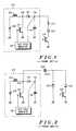
- FIG. 3shows a first embodiment of the light emitting diode (LED) driving circuit of the present invention.
- LEDlight emitting diode
- At least two LEDs 32 , 36are coupled between first and second nodes 38 , 37 .
- a first LED 32is coupled in a forward current path 30 between first and second nodes 38 , 37 .
- a second LED 36is coupled in a reverse current path 34 between the second and first nodes 37 , 38 .
- an anode of the first LED 32is coupled to a cathode of the second LED 36 at the first node 38 and a cathode of the first LED 32 is coupled to an anode of the second LED 36 at the second node 37 .
- the driving circuitalso includes a power supply (not shown) for producing a substantially periodic waveform.
- the waveformis substantially a square wave.
- the power supplyis typically derived from a battery and is coupled to drive the first node 38 with voltage pulses.
- a capacitor C with first and second terminalsis included. The first terminal is coupled to the second node 37 of the at least two LEDs 32 , 36 .
- the capacitorstores charge from the power supply while the power supply is driving the first LED 32 in the forward current path 30 during voltage pulses, i.e. when the voltage pulse is high.
- a discharge circuit 35is coupled between the second terminal of the capacitor and the first node 38 of the at least two LEDs 32 , 36 .
- the discharge circuit 35drains charge from the capacitor to drive the second LED 36 in the reverse current path 34 between voltage pulses, i.e. when the voltage pulse is low.
- the discharge circuitis an inverter with an input coupled to the first node 38 and an output coupled to the second terminal of the capacitor.
- the stored charge of the capacitorboosts the voltage available to the second LED 36 over a voltage available from the voltage pulses of the power supply. This provides an advantage where the second LED 36 requires a higher drive voltage than the first LED 32 . Is this case, the boosted voltage available during the discharge of the capacitor equalizes photonic output between the LEDs
- the power supplyis buffered by an inverter 42 driven by a square wave as seen in FIG. 4, wherein components common to FIG. 3 are numbered similarly.
- a current limiting inductor 40is coupled to the first node 38 to limit charge current to the capacitor. Because different charging and discharging current exist in the present invention it is beneficial to optimize the LEDs, capacitor, and a duty cycle of the power supply to provide uniform average photonic output from the LEDs
- I c[V 0 ⁇ V th ⁇ V c ( t )]/ R (1)
- V 0is the power supply or battery voltage
- V this the LED threshold voltage
- V c (t)is the voltage on the capacitor C
- Ris the total circuit resistance
- I 0( V 0 ⁇ V th ⁇ V c0 )/ R (5)
- I c — ave( V 0 ⁇ V th ⁇ V c0 ) C ⁇ 1 ⁇ exp( ⁇ [ T c /( RC )] ⁇ / T c (6)
- T cis the charging time
- I D[V 0 ⁇ V thw +V c ( t )] /R D (7)
- V c ( t )[ V 0 ⁇ V thw +V ch ]exp[ ⁇ t /( R D C )] +V thw ⁇ V 0 (10)
- V chis the voltage across the capacitor before discharging.
- the current during the discharge processcan be calculated with equation (7) and equation (10).
- I D[V 0 ⁇ V thw +V ch ] ⁇ 1 ⁇ exp[ ⁇ t /( R D C )] ⁇ /R D (11)
- the average discharging currentcan be computed from (11):
- I D — aveC[V 0 ⁇ V thw +V ch ]exp[ ⁇ T D /( R D C )]/ T D (12)
- the efficiencycan be further improved by adding an inductor in the circuit ( 40 of FIG. 4 ).
- an inductor in series with the capacitor in the discharging path to reduce the maximum discharging currentWith an inductor in series with the capacitor in the discharging path to reduce the maximum discharging current, the differential equation for the current becomes:
- a 1 and A 2are two constants to be determined by the initial conditions.
- the constant A and Bare given by the following expressions:
- I Lmax[( V 0 +V ch ⁇ V thw )/ R]e ⁇ 0.5 ⁇ (R/L) R ( C/L ) 1/2 (22)
- the maximum discharging currentcan be reduced by adding an inductor in series with the capacitor.
- Maximum currentcan also be reducing by limiting the discharging time, because the peak current does not happen at the beginning of the discharge cycle when there is inductance in the circuit.
- the efficiency of the driving circuit(with inductive current limitation) is determined by the ratio of the power consumed by the LED and the total power from the power source, which is described in the following equation
- Color LCDswill become very popular in the future hand held devices. Thus white LEDs will also become popular in these devices due to the backlighting requirements of the color LCD.
- white LED driversare available in the marketplace, none of the designs are high efficiency and require high driving voltages.
- the present inventioncan reduce the power consumption by more than 25%, which results in longer battery life. Further, LEDs have recently been incorporated into flashlights for their high photon efficiency. The present invention allows reduces the power consumption in these, so that the battery life can be 25% longer than a LED flashlight a using constant current driven method.
- LEDsalso have the same characteristics as a general purpose diode, thus they can be used as switch device such as that in a charge pump.
- the threshold voltage of green, yellow and red LEDsranges from 1.8V to 2.4V.
- a buck mode switch regulatorcan be used to increase the power efficiency, this results in cost increase.
- the threshold voltage of blue and white LEDsranges from 3.3V to 4.2V.
- a lithium ion battery voltagetypically ranges from 3.0V to 4.2V with 95% of capacity in the range from 3.4V to 4.2V.
- the present inventioncan have high power efficiency of 90% or more.
- Table 1compares the power consumption of the present invention compared to prior art light drivers.
- each green LEDis driven with a two-volt buck converter with 80% efficiency, resulting in an equivalent 3.5 mA current draw from a 3.6V battery.
- each white LEDis driven with a five-volt boost converter with 80% efficiency, resulting in an equivalent 35 mA current draw from a 3.6V battery.
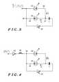
- FIG. 5shows a simplified schematic diagram for a green LED driver for monochromatic lighting, wherein the power supply charges capacitor C through parallel LEDs D 1 and D 2 . Then C discharges through green series LEDs D 3 and D 4 as more voltage is available in the discharge cycle to drive series connected LEDs. As a result, the LED brightness of four LEDs is obtained at the current drain of three LEDs. In practice, more parallel LEDs can be provided in the forward current path and parallel sets of two series LEDs can be provided in the reverse path to increment brightness as needed.
- FIG. 6shows a simplified schematic diagram for a RGB LED driver for color LCD lighting, wherein the power supply charges capacitor C through a red LED D 1 and a yellow LED D 2 . Then C discharges through parallel blue LEDs D 3 and D 4 as more voltage is available in the discharge cycle to drive the higher threshold blue (or white) LEDs. The reason to use blue LEDs in parallel is to lower the maximum current through the blue LED and improve photon efficiency.
- an inductor Lcan be put in the charge path to achieve zero current switching and maximize the electrical efficiency.
- Another inductor L in the discharge pathcan reduce peak discharge current and improve the photon efficiency.
- both charge peak current and discharge peak currentcan be reduced, and thus the highest photon efficiency can be achieved.
- a green and white LED driver for color LCD lightingcan be provided with green LEDs in the charge circuit path and white LEDs in the discharge current path.
- a comparator(not shown) can be used to monitor the charging voltage on C when the circuit is charging through the forward current path, such that once the voltage on C is greater than a charging threshold voltage, the comparator can direct C to start discharging through the discharge current path by having the threshold voltage of the comparator change to a higher discharge threshold voltage.
- the circuitstarts charging C and changes the comparator threshold to the charging threshold voltage from the discharging threshold voltage. This can be used advantageously as a brightness, contrast, or dimming control.
Landscapes
- Circuit Arrangement For Electric Light Sources In General (AREA)
- Control Of Indicators Other Than Cathode Ray Tubes (AREA)
- Dc-Dc Converters (AREA)
Abstract
Description
This invention relates generally to light emitting diode (LED) circuits, and more particularly to driver circuits for driving LEDs.
In portable radio communication devices it is desirable to prolong the operating time and battery life. To reduce the current drain from the battery it is desirable to develop circuits that achieve the lowest power consumption possible. Among those circuits, the display draws a disproportionate amount of current from the battery. The LED is widely used for back lighting in devices such as cellular phones due to its simpler driving circuit compared with the electroluminescent (EL) and fluorescent lighting its comparably lower cost and noise. However, the power consumption of LEDs is generally higher than the EL lights when multiple LEDs are used. In addition, the use of white LEDs, which is necessary for backlighting color liquid crystal displays (LCDs), incurs power considerations in that white LEDs have higher threshold voltages, which are often higher than the battery voltages. Thus DC-DC converter is required to boost the battery voltage and the overall power efficiency is reduced.
A radio communication device, such as a cellular phone, is typically powered from a battery, such as a lithium-ion battery, having a normal operating voltage of about 3.6 volts. Ideally, the device circuits are powered directly from the battery, however, some circuits such as light emitting diodes (LEDs) used in displays will not operate at this low voltage or provide deteriorated performance when the battery runs down, and it becomes necessary to add a DC-DC converter to step-up the voltage. However, the inductor type of DC-DC converter may have a typical efficiency of 85%, while the charge pump type of DC-DC converter usually has efficiencies less than 50% when the battery internal resistance is considered.
Referring to FIG. 1, a prior art LED inductive boost driver circuit is illustrated as described in U.S. Pat. No. 4,673,865, including an inductiveswitching power supply 102 to perform a DC-DC conversion. Aninductor 104 is connected between anode 106 and abattery 108. Atransistor 110 is connected tonode 106. The anode of adiode 112 is also connected tonode 106 and the cathode is connected to anode 114. Afilter capacitor 116 is connected betweennode 114 and ground. Aduty cycle modulator 118 is connected betweennode 114 and the base oftransistor 110.
In operation,duty cycle modulator 118 periodically switches on and offtransistor 110. Whentransistor 110 is switched on, current frombattery 108 begins to flow throughinductor 104, building up the magnetic field in the inductor as the current increases. Whentransistor 110 is switched off, the magnetic field collapses and a positive voltage pulse appears atnode 106. Becauseinductor 104 is in series withbattery 108, the voltage of the pulse atnode 106 is greater than the battery voltage.
Thus, the periodic switching oftransistor 110 causes a string of pulses to appear atnode 106. These voltage pulses are then rectified and filtered bydiode 112 andfilter capacitor 116 to produce a multiplied DC voltage atoutput node 114. To regulate the output voltage,duty cycle modulator 118 samples the output voltage atDC output node 114 and adjusts the duty cycle oftransistor 110 so that the DC output voltage remains substantially constant. A current limitingresistor 124 is coupled in series with theLED 122 along with atransistor 126 to control the activation ofLED 122 via a control circuit (not shown). Although an improvement in the art, there is voltage drop acrossdiode 112, and power consumed in current limitingresistor 124, which consumes battery power.
Illustrated in FIG. 2 is another prior art LED driver circuit that consumes less battery energy than the device of FIG.1. The driver circuit usesswitching power supply 102,LED 122 andtransistor 126 that were previously described in conjunction with FIG.1. Also,LED 122 andtransistor 126 are mutually interconnected as in FIG.1 andtransistor 126 functions to control the activation ofLED 122 as previously described. However, acapacitor 202 is connected between the anode ofLED 122 and thepulse output node 106. A shunt diode204 is connected to the junction ofcapacitor 202 andLED 122.
In operation, during a positive voltage pulse atoutput node 106, current flows throughLED 122 viacoupling capacitor 202. Thecapacitor plate 202aofcapacitor 202 begins to charge negatively. Between voltage pulses, i.e. whentransistor 110 conducts and momentarilygrounds node 106,capacitor plate 202agoes below ground potential. When the negative potential oncapacitor plate 202ais sufficient to overcome the small (typically 0.6 Volts) forward voltage drop across diode204, the diode conducts, substantially dischargingcapacitor 202. Thus, diode204 provides a means for dischargingcapacitor 202 during a portion of each period of the voltage waveform atoutput node 106.
Unfortunately, the discharge current is lost, lowering efficiency of the driver circuit. Moreover, this device, as well as that of FIG. 2, utilizes an inductor type boost converter to provide a high supply voltage, which increases cost and size of the circuit.
What is needed is a high efficiency LED driver circuit that can drive LEDs requiring higher voltage than available battery power. It would also be of benefit to eliminate the inductive type of boost circuits and the losses associated with current limiting resistors and switching circuits. It would also be advantageous to accomplish this in a low cost, simple circuit architecture.
FIGS. 1 and 2 show schematic diagrams of a prior art LED driver circuits;
FIG. 3 shows a schematic diagram of a first embodiment of a LED driver circuit, in accordance with the present invention;
FIG. 4 shows a schematic diagram of a preferred embodiment of a LED driver circuit, in accordance with the present invention;
FIG. 5 shows a schematic diagram of a first alternate embodiment of a LED driver circuit, in accordance with the present invention; and
FIG. 6 shows a schematic diagram of a second alternate embodiment of a LED driver circuit, in accordance with the present invention.
The present invention provides a high efficiency LED driver with LED switching whereas prior art devices utilized diode or transistor switching. In particular, the present invention provides an improved driving circuit with more than90% power efficiency for LED lighting devices. This is accomplished with LEDs requiring a driving voltage greater than the available power supply voltage. This is also accomplished without the typical inductive boost circuits or current limiting resistors of the prior art, and is implemented in a simple circuit architecture.
FIG. 3 shows a first embodiment of the light emitting diode (LED) driving circuit of the present invention. At least twoLEDs second nodes first LED 32 is coupled in a forwardcurrent path 30 between first andsecond nodes second LED 36 is coupled in a reversecurrent path 34 between the second andfirst nodes first LED 32 is coupled to a cathode of thesecond LED 36 at thefirst node 38 and a cathode of thefirst LED 32 is coupled to an anode of thesecond LED 36 at thesecond node 37. The driving circuit also includes a power supply (not shown) for producing a substantially periodic waveform. Preferably, the waveform is substantially a square wave. The power supply is typically derived from a battery and is coupled to drive thefirst node 38 with voltage pulses. A capacitor C with first and second terminals is included. The first terminal is coupled to thesecond node 37 of the at least twoLEDs first LED 32 in the forwardcurrent path 30 during voltage pulses, i.e. when the voltage pulse is high. Adischarge circuit 35 is coupled between the second terminal of the capacitor and thefirst node 38 of the at least twoLEDs discharge circuit 35 drains charge from the capacitor to drive thesecond LED 36 in the reversecurrent path 34 between voltage pulses, i.e. when the voltage pulse is low. Preferably, the discharge circuit is an inverter with an input coupled to thefirst node 38 and an output coupled to the second terminal of the capacitor. The stored charge of the capacitor boosts the voltage available to thesecond LED 36 over a voltage available from the voltage pulses of the power supply. This provides an advantage where thesecond LED 36 requires a higher drive voltage than thefirst LED 32. Is this case, the boosted voltage available during the discharge of the capacitor equalizes photonic output between the LEDs
In a preferred embodiment, the power supply is buffered by aninverter 42 driven by a square wave as seen in FIG. 4, wherein components common to FIG. 3 are numbered similarly. In addition, a current limitinginductor 40 is coupled to thefirst node 38 to limit charge current to the capacitor. Because different charging and discharging current exist in the present invention it is beneficial to optimize the LEDs, capacitor, and a duty cycle of the power supply to provide uniform average photonic output from the LEDs
In operation during charging, and referring back to FIG. 3, the current in the forwardcurrent path 30 going through theLED 32 is given by:
Where V0is the power supply or battery voltage, Vthis the LED threshold voltage, Vc(t) is the voltage on the capacitor C, and R is the total circuit resistance. From equation (1), one can get:
Because dVc(t)=∫Icdt/C, equation (2) becomes
The solution of equation (3) is:
Where
I0=(V0−Vth−Vc0)/R (5)
From equation (4), the average current for the charging process is given by:
where Tcis the charging time.
When discharging through the reversecurrent path 34, the capacitor C is in series with the power supply. Thus the total voltage is increased to the power supply voltage plus the voltage on the capacitor. The current during the discharging is given by the following equation:
From equation (7), one can get:
From dVc(t)=−∫IDdt/C, one can get:
where RDis the total resistance in the discharge circuit, and Vthwis thesecond LED 36 threshold voltage. The solution of equation (9) is given by:
where Vchis the voltage across the capacitor before discharging. The current during the discharge process can be calculated with equation (7) and equation (10).
ID=[V0−Vthw+Vch]{1−exp[−t/(RDC)]}/RD (11)
The average discharging current can be computed from (11):
The efficiency can be further improved by adding an inductor in the circuit (40 of FIG.4). With an inductor in series with the capacitor in the discharging path to reduce the maximum discharging current, the differential equation for the current becomes:
The solution is given by:
Where A1 and A2 are two constants to be determined by the initial conditions. The constant A and B are given by the following expressions:
It is known that the current is zero at the moment when the circuit is connected, then the current ramps up at a rate determined by the nature of the circuit. From this initial condition, one can find that:
At the moment when the circuit starts discharging, it cannot be determined if there is a capacitor in the circuit by monitoring the current. Thus, one can induce that the gradient of the current is the same as the circuit with the same initial voltage but without the capacitor at the moment when the circuit starts discharging. This gives another initial condition as follows:
From equations (14) through (18), one can get:
With this complete solution, the maximum discharging current can be found and compared with the maximum current in the circuit without inductance. By setting dI/dt=0, we have:
Where τ is the time when the discharging current reaches its maximum. By substituting equations (15) and (16) into equation (20), one obtains:
Substituting equation (21) into equation (19) gives the maximum discharging current:
For any given value of C, a value for L can be found to meet the requirement that:
In this way, the maximum discharging current can be reduced by adding an inductor in series with the capacitor. Maximum current can also be reducing by limiting the discharging time, because the peak current does not happen at the beginning of the discharge cycle when there is inductance in the circuit.
The efficiency of the driving circuit (with inductive current limitation) is determined by the ratio of the power consumed by the LED and the total power from the power source, which is described in the following equation
Given typical values of IC— ave=170 mA, ID— ave=500 mA, Vthw=3.8V for a white LED, Vth=1.8V for a green/red/yellow LED and Vin=3.6V, the efficiency of the present invention is η=0.91.
Color LCDs will become very popular in the future hand held devices. Thus white LEDs will also become popular in these devices due to the backlighting requirements of the color LCD. Although white LED drivers are available in the marketplace, none of the designs are high efficiency and require high driving voltages. The present invention can reduce the power consumption by more than 25%, which results in longer battery life. Further, LEDs have recently been incorporated into flashlights for their high photon efficiency. The present invention allows reduces the power consumption in these, so that the battery life can be 25% longer than a LED flashlight a using constant current driven method.
Many considerations must be made in optimizing a circuit for the various LEDs available in the marketplace, their applications and the availability of lithium ion batteries for power sources. For example, With exception of GaP red LEDs, blue LEDs and white LEDs, most of the modern ultra-bright LEDs have maximum efficiency at currents near or just below their maximum rated current. Also, with the exception of GaP red, blue LEDs and white LEDs, LED optical characteristics in the high-power zone are excellent, permitting effective pulse driving. In other words, for the same optical output the green, red and yellow LEDs can be driven with very high pulse current but lower average current. Blue and white LEDs have higher optical efficiency at lower current. LEDs also have the same characteristics as a general purpose diode, thus they can be used as switch device such as that in a charge pump. The threshold voltage of green, yellow and red LEDs ranges from 1.8V to 2.4V. Although, a buck mode switch regulator can be used to increase the power efficiency, this results in cost increase. In contrast, the threshold voltage of blue and white LEDs ranges from 3.3V to 4.2V. A lithium ion battery voltage typically ranges from 3.0V to 4.2V with 95% of capacity in the range from 3.4V to 4.2V.
With the combination of pulse driving, using red, green or yellow LEDs as switching diode in a charge pump, and using the charge pump output to drive blue or white LEDs, the present invention can have high power efficiency of 90% or more. Table 1 compares the power consumption of the present invention compared to prior art light drivers.
| TABLE 1 |
| Comparison of different lighting technologies |
| LED driver | ||||
| of present | Constant current | Compact | ||
| invention | LED driver | fluorescent | ||
| Lighting | 8 green LED | 8 green LED and 2 | 2 white CCFL |
| components | and 4 white | white LED | tube + 8 |
| LED | green LED | ||
| Battery voltage | 3.6 V | 3.6 V | 3.6 V |
| DC—DC converter | LED charge | Boost converter | Boost |
| pump | converter | ||
| Driving method | Pulsed | Constant current | High voltage |
| AC | |||
| Average current for | 4 mA | 5 mA | 5 mA |
| each green LED | |||
| Average current for | 10 mA | 20 mA | N/A |
| each white LED | |||
| Average FL current | N/A | N/A | 52 mA |
| drain from battery | |||
| Total average | 72 mA | 98 mA | 80 mA |
| current drain from | |||
| battery | |||
In the prior art drivers, it is assumed that each green LED is driven with a two-volt buck converter with 80% efficiency, resulting in an equivalent 3.5 mA current draw from a 3.6V battery. Similarly, each white LED is driven with a five-volt boost converter with 80% efficiency, resulting in an equivalent 35 mA current draw from a 3.6V battery.
In order to get high efficiency driving circuits, issues like the tolerance of the LED threshold voltage, the LED forward current—photon efficiency relation and dimming control need to be resolved. The following preferred embodiments provide high efficiency designs for practical applications.
FIG. 5 shows a simplified schematic diagram for a green LED driver for monochromatic lighting, wherein the power supply charges capacitor C through parallel LEDs D1 and D2. Then C discharges through green series LEDs D3 and D4 as more voltage is available in the discharge cycle to drive series connected LEDs. As a result, the LED brightness of four LEDs is obtained at the current drain of three LEDs. In practice, more parallel LEDs can be provided in the forward current path and parallel sets of two series LEDs can be provided in the reverse path to increment brightness as needed.
FIG. 6 shows a simplified schematic diagram for a RGB LED driver for color LCD lighting, wherein the power supply charges capacitor C through a red LED D1 and a yellow LED D2. Then C discharges through parallel blue LEDs D3 and D4 as more voltage is available in the discharge cycle to drive the higher threshold blue (or white) LEDs. The reason to use blue LEDs in parallel is to lower the maximum current through the blue LED and improve photon efficiency. In the case when the forward current charge path DC resistance is very small, an inductor L can be put in the charge path to achieve zero current switching and maximize the electrical efficiency. Another inductor L in the discharge path can reduce peak discharge current and improve the photon efficiency. If the inductor L is put in series with the capacitor, both charge peak current and discharge peak current can be reduced, and thus the highest photon efficiency can be achieved. Similarly, a green and white LED driver for color LCD lighting can be provided with green LEDs in the charge circuit path and white LEDs in the discharge current path.
It is also envisioned that a comparator (not shown) can be used to monitor the charging voltage on C when the circuit is charging through the forward current path, such that once the voltage on C is greater than a charging threshold voltage, the comparator can direct C to start discharging through the discharge current path by having the threshold voltage of the comparator change to a higher discharge threshold voltage. When the discharging voltage is lower than the discharge threshold voltage, the circuit starts charging C and changes the comparator threshold to the charging threshold voltage from the discharging threshold voltage. This can be used advantageously as a brightness, contrast, or dimming control.
While the invention has been described in the context of a preferred embodiment, it will be apparent to those skilled in the art that the present invention may be modified in numerous ways and may assume many embodiments other than that specifically set out and described above. Accordingly, it is intended by the appended claims to cover all modifications of the invention that fall within the broad scope of the invention.
Claims (20)
1. A light emitting diode (LED) driving circuit, comprising:
at least two LEDs coupled between first and second nodes, a first LED being coupled in a forward current path between first and second nodes and a second LED being coupled in a reverse current path between the second and first nodes, respectively;
a power supply for producing a substantially periodic waveform, the power supply being coupled to drive the first node with voltage pulses;
a capacitor with a first and a second terminal, the first terminal is coupled to the second node of the at least two LEDs, the capacitor stores charge from the power supply while the power supply is driving the first LED in the forward current path during voltage pulses; and
a discharge circuit coupled between the second terminal of the capacitor and the first node of the at least two LEDs, wherein the discharge circuit drains charge from the capacitor to drive the second LED in the reverse current path between voltage pulses.
2. The circuit ofclaim 1 , wherein the periodic waveform is substantially a square wave.
3. The circuit ofclaim 1 , wherein the discharge circuit is an inverter with an input coupled to the first node and an output coupled to the second terminal of the capacitor.
4. The circuit ofclaim 1 , wherein the power supply includes an inverter driven by a square wave.
5. The circuit ofclaim 1 , wherein the stored charge of the capacitor boosts the voltage available to the second LED over a voltage available from the voltage pulses of the power supply.
6. The circuit ofclaim 5 , wherein the second LED requires a higher drive voltage than the first LED such that the boosted voltage available during the discharge of the capacitor equalizes photonic output between the LEDs.
7. The circuit ofclaim 1 , wherein the LEDs, capacitor, and a duty cycle of the power supply are optimized to provide uniform average photonic output from the LEDs.
8. The circuit ofclaim 1 , wherein the at least two LEDs include a first and a second LED, an anode of the first LED being coupled to a cathode of the second LED at the first node and a cathode of the first LED being coupled to an anode of the second LED at the second node.
9. The circuit ofclaim 1 , further comprising an inductor coupled to the first node to limit charge current to the capacitor.
10. The circuit ofclaim 1 , wherein the at least two LEDs includes two LEDs coupled in the forward current path and two LEDs coupled in the reverse current path, the LEDs in each current path being coupled in one of the group of a parallel connection and a series connection.
11. The circuit ofclaim 10 , wherein the LEDs in the forward current path are further connected in series with a current limiting inductor.
12. The circuit ofclaim 10 , wherein the LEDs in the forward current path are connected in series and the LEDs in the reverse current path are connected in parallel.
13. A light emitting diode (LED) driving circuit, comprising:
at least two LEDs coupled between first and second nodes, a first LED being coupled in a forward current path between first and second nodes and a second LED being coupled in a reverse current path between the second and first nodes, respectively, an anode of the first LED being coupled to a cathode of the second LED at the first node and a cathode of the first LED being coupled to an anode of the second LED at the second node;
a power supply for driving the first node with voltage pulses having a substantially square waveform;
a capacitor with a first and a second terminal, the first terminal is coupled to the second node of the at least two LEDs, the capacitor stores charge from the power supply while the power supply is driving the first LED in the forward current path during voltage pulses; and
a discharge circuit coupled between the second terminal of the capacitor and the first node of the at least two LEDs, wherein the discharge circuit drains charge from the capacitor to drive the second LED in the reverse current path between voltage pulses, the stored charge of the capacitor boosts the voltage available to the second LED over a voltage available from the voltage pulses of the power supply.
14. The circuit ofclaim 13 , wherein the discharge circuit is an inverter with an input coupled to the first node and an output coupled to the second terminal of the capacitor.
15. The circuit ofclaim 13 , wherein the power supply includes an inverter driven by a square wave.
16. The circuit ofclaim 13 , wherein the second LED requires a higher drive voltage than the first LED such that the boosted voltage available during the discharge of the capacitor equalizes photonic output between the LEDs.
17. The circuit ofclaim 13 , wherein the LEDs, capacitor, and a duty cycle of the power supply are optimized to provide uniform average output from the LEDs.
18. The circuit ofclaim 13 , further comprising an inductor coupled to the first node to limit charge current to the capacitor.
19. The circuit ofclaim 13 , wherein the at least two LEDs includes two LEDs coupled in the forward current path and two LEDs coupled in the reverse current path, the LEDs in each current path being coupled in one of the group of a parallel connection and a series connection.
20. A light emitting diode (LED) driving circuit, comprising:
at least two LEDs coupled between first and second nodes, a first LED being coupled in a forward current path between first and second nodes and a second LED being coupled in a reverse current path between the second and first nodes, respectively, an anode of the first LED being coupled to a cathode of the second LED at the first node and a cathode of the first LED being coupled to an anode of the second LED at the second node;
a power supply for driving the first node with voltage pulses having a substantially square waveform;
a capacitor with a first and a second terminal, the first terminal is coupled to the second node of the at least two LEDs, the capacitor stores charge from the power supply while the power supply is driving the first LED in the forward current path during voltage pulses; and
a discharge circuit coupled between the second terminal of the capacitor and the first node of the at least two LEDs, wherein the discharge circuit drains charge from the capacitor to drive the second LED in the reverse current path between voltage pulses, the stored charge of the capacitor boosts the voltage available to the second LED over a voltage available from the voltage pulses of the power supply, the second LED requires a higher drive voltage than the first LED such that the boosted voltage available during the discharge of the capacitor equalizes photonic output between the LEDs.
Priority Applications (1)
| Application Number | Priority Date | Filing Date | Title |
|---|---|---|---|
| US09/754,485US6359392B1 (en) | 2001-01-04 | 2001-01-04 | High efficiency LED driver |
Applications Claiming Priority (1)
| Application Number | Priority Date | Filing Date | Title |
|---|---|---|---|
| US09/754,485US6359392B1 (en) | 2001-01-04 | 2001-01-04 | High efficiency LED driver |
Publications (1)
| Publication Number | Publication Date |
|---|---|
| US6359392B1true US6359392B1 (en) | 2002-03-19 |
Family
ID=25035001
Family Applications (1)
| Application Number | Title | Priority Date | Filing Date |
|---|---|---|---|
| US09/754,485Expired - LifetimeUS6359392B1 (en) | 2001-01-04 | 2001-01-04 | High efficiency LED driver |
Country Status (1)
| Country | Link |
|---|---|
| US (1) | US6359392B1 (en) |
Cited By (55)
| Publication number | Priority date | Publication date | Assignee | Title |
|---|---|---|---|---|
| US6486726B1 (en)* | 2001-05-18 | 2002-11-26 | Eugene Robert Worley, Sr. | LED driver circuit with a boosted voltage output |
| US20030112229A1 (en)* | 2001-12-14 | 2003-06-19 | Pong Man Hay | High efficiency driver for color light emitting diodes (LED) |
| US20030122502A1 (en)* | 2001-12-28 | 2003-07-03 | Bernd Clauberg | Light emitting diode driver |
| US6674269B1 (en)* | 2002-09-23 | 2004-01-06 | Xerox Corporation | Light emitting diode driver and image forming device including the same |
| US20040119679A1 (en)* | 2002-12-19 | 2004-06-24 | Garcia Marcella A. | Method and system for LCD panel light source selection |
| US20040170037A1 (en)* | 2001-07-19 | 2004-09-02 | Bucks Marcel Johannes Maria | Led switching arrangement |
| US20050053895A1 (en)* | 2003-09-09 | 2005-03-10 | The Procter & Gamble Company Attention: Chief Patent Counsel | Illuminated electric toothbrushes emitting high luminous intensity toothbrush |
| US20050091905A1 (en)* | 2003-10-31 | 2005-05-05 | Larson Robert A. | Lighted fish landing net |
| US20050212459A1 (en)* | 2004-03-26 | 2005-09-29 | Patel Sanmukh M | System and method for driving a plurality of loads |
| US20050243041A1 (en)* | 2004-04-29 | 2005-11-03 | Micrel, Incorporated | Light emitting diode driver circuit |
| US6980119B2 (en) | 2002-06-26 | 2005-12-27 | Sws Star Warning Systems Inc. | Solid-state warning light with environmental control |
| US20060033442A1 (en)* | 2004-08-11 | 2006-02-16 | D Angelo Kevin P | High efficiency LED driver |
| DE102004031689A1 (en)* | 2004-06-30 | 2006-02-16 | Osram Opto Semiconductors Gmbh | Light-emitting diode device, has e.g. pulse-width modulator for supplying current to two antiparallel-connected LEDs |
| US20070080652A1 (en)* | 2003-11-13 | 2007-04-12 | Koninklijke Philips Electronics N.V. | Resonant power led control circuit with brightness and color control |
| US20070115248A1 (en)* | 2005-11-18 | 2007-05-24 | Roberts John K | Solid state lighting panels with variable voltage boost current sources |
| WO2007061811A1 (en)* | 2005-11-18 | 2007-05-31 | Cree, Inc. | Solid state lighting panels with variable voltage boost current sources |
| US20070171145A1 (en)* | 2006-01-25 | 2007-07-26 | Led Lighting Fixtures, Inc. | Circuit for lighting device, and method of lighting |
| US20080088248A1 (en)* | 2006-09-13 | 2008-04-17 | Led Lighting Fixtures, Inc. | Circuitry for supplying electrical power to loads |
| US20080297644A1 (en)* | 2004-06-30 | 2008-12-04 | Nadir Farchtchian | Light-Emitting Diode Arrangement, Optical Recording Device and Method for the Pulsed Operation of at Least One Light-Emitting Diode |
| US7468723B1 (en) | 2005-03-04 | 2008-12-23 | National Semiconductor Corporation | Apparatus and method for creating large display back-lighting |
| US20100126286A1 (en)* | 2007-04-06 | 2010-05-27 | Brian Austin Self | Open platform automated sample processing system |
| EP2227068A1 (en)* | 2009-03-06 | 2010-09-08 | Siemens Aktiengesellschaft | Alternating transmission of electromagnetic radiation with two radiation sources |
| US7852010B2 (en) | 2006-05-31 | 2010-12-14 | Cree, Inc. | Lighting device and method of lighting |
| GB2474877A (en)* | 2009-10-29 | 2011-05-04 | Dalmatic Lystrup As | Adjustable safety barrier transmitter |
| US20110193489A1 (en)* | 2008-10-10 | 2011-08-11 | Koninklijke Philips Electronics N.V. | Methods and apparatus for controlling multiple light sources via a single regulator circuit to provide variable color and/or color temperature light |
| US8203281B2 (en) | 2008-04-29 | 2012-06-19 | Ivus Industries, Llc | Wide voltage, high efficiency LED driver circuit |
| US8373627B1 (en)* | 2003-07-31 | 2013-02-12 | Wavefront Research, Inc. | Low power optical interconnect driver circuit |
| US8476837B2 (en) | 2010-07-02 | 2013-07-02 | 3M Innovative Properties Company | Transistor ladder network for driving a light emitting diode series string |
| US8558482B2 (en) | 2011-02-22 | 2013-10-15 | GRE Alpha Electronics Ltd. Institute Company Limited | Programmable current PWM dimming controller |
| US20140021878A1 (en)* | 2012-07-23 | 2014-01-23 | Osram Gmbh | Buck Converter for Operating at Least One LED |
| US20140078755A1 (en)* | 2010-10-21 | 2014-03-20 | General Electric Company | Lighting system with thermal management system having point contact synthetic jets |
| US8858031B2 (en) | 2010-07-22 | 2014-10-14 | Independence Led Lighting, Llc | Light engine device with direct to linear system driver |
| US8993951B2 (en) | 1996-03-25 | 2015-03-31 | Magna Electronics Inc. | Driver assistance system for a vehicle |
| US9107256B2 (en) | 2011-09-22 | 2015-08-11 | Samsung Electronics Co., Ltd. | Light emitting diode lighting apparatus |
| US9171217B2 (en) | 2002-05-03 | 2015-10-27 | Magna Electronics Inc. | Vision system for vehicle |
| US9191634B2 (en) | 2004-04-15 | 2015-11-17 | Magna Electronics Inc. | Vision system for vehicle |
| US9254506B2 (en) | 2010-07-02 | 2016-02-09 | 3M Innovative Properties Company | Moisture resistant coating for barrier films |
| US9315151B2 (en) | 2000-03-02 | 2016-04-19 | Magna Electronics Inc. | Driver assist system for vehicle |
| US9436880B2 (en) | 1999-08-12 | 2016-09-06 | Magna Electronics Inc. | Vehicle vision system |
| US9440586B2 (en) | 2002-08-21 | 2016-09-13 | Magna Electronics Inc. | Multi-camera vision system for a vehicle |
| US9440535B2 (en) | 2006-08-11 | 2016-09-13 | Magna Electronics Inc. | Vision system for vehicle |
| US9508014B2 (en) | 2013-05-06 | 2016-11-29 | Magna Electronics Inc. | Vehicular multi-camera vision system |
| US9516723B2 (en) | 2010-07-14 | 2016-12-06 | General Electric Company | System and method for driving light emitting diodes |
| DE10356608B4 (en)* | 2002-12-03 | 2017-09-28 | Philips Lighting North America Corporation | Lighting arrangement and liquid crystal display |
| US9900522B2 (en) | 2010-12-01 | 2018-02-20 | Magna Electronics Inc. | System and method of establishing a multi-camera image using pixel remapping |
| CN108337776A (en)* | 2006-08-18 | 2018-07-27 | 晶元光电股份有限公司 | Lighting device |
| US10144353B2 (en) | 2002-08-21 | 2018-12-04 | Magna Electronics Inc. | Multi-camera vision system for a vehicle |
| US10187590B2 (en) | 2015-10-27 | 2019-01-22 | Magna Electronics Inc. | Multi-camera vehicle vision system with image gap fill |
| US10493916B2 (en) | 2012-02-22 | 2019-12-03 | Magna Electronics Inc. | Vehicle camera system with image manipulation |
| US10793067B2 (en) | 2011-07-26 | 2020-10-06 | Magna Electronics Inc. | Imaging system for vehicle |
| US10939525B2 (en) | 2019-04-18 | 2021-03-02 | Goodrich Lighting Systems, Inc. | Driving light emitting diodes and display apparatus |
| US11277558B2 (en) | 2016-02-01 | 2022-03-15 | Magna Electronics Inc. | Vehicle vision system with master-slave camera configuration |
| US11433809B2 (en) | 2016-02-02 | 2022-09-06 | Magna Electronics Inc. | Vehicle vision system with smart camera video output |
| US11617316B2 (en)* | 2017-11-10 | 2023-04-04 | James S. Ray | Apparatus and methods for a hydroponics system with enhanced heat transfer |
| US12349638B2 (en) | 2017-11-10 | 2025-07-08 | James S. RAY, JR. | Apparatus and methods for a hydroponics system with light control |
Citations (5)
| Publication number | Priority date | Publication date | Assignee | Title |
|---|---|---|---|---|
| US3869641A (en)* | 1972-06-21 | 1975-03-04 | Monsanto Co | AC Responsive led pilot light circuitry |
| US4673865A (en) | 1986-04-04 | 1987-06-16 | Motorola, Inc. | Charge coupled LED driver circuit |
| US4965561A (en) | 1986-01-08 | 1990-10-23 | Karel Havel | Continuously variable color optical device |
| US5575459A (en)* | 1995-04-27 | 1996-11-19 | Uniglo Canada Inc. | Light emitting diode lamp |
| US6285140B1 (en)* | 1999-04-21 | 2001-09-04 | Pharos Innovations Inc. | Variable-effect lighting system |
- 2001
- 2001-01-04USUS09/754,485patent/US6359392B1/ennot_activeExpired - Lifetime
Patent Citations (5)
| Publication number | Priority date | Publication date | Assignee | Title |
|---|---|---|---|---|
| US3869641A (en)* | 1972-06-21 | 1975-03-04 | Monsanto Co | AC Responsive led pilot light circuitry |
| US4965561A (en) | 1986-01-08 | 1990-10-23 | Karel Havel | Continuously variable color optical device |
| US4673865A (en) | 1986-04-04 | 1987-06-16 | Motorola, Inc. | Charge coupled LED driver circuit |
| US5575459A (en)* | 1995-04-27 | 1996-11-19 | Uniglo Canada Inc. | Light emitting diode lamp |
| US6285140B1 (en)* | 1999-04-21 | 2001-09-04 | Pharos Innovations Inc. | Variable-effect lighting system |
Cited By (128)
| Publication number | Priority date | Publication date | Assignee | Title |
|---|---|---|---|---|
| US8993951B2 (en) | 1996-03-25 | 2015-03-31 | Magna Electronics Inc. | Driver assistance system for a vehicle |
| US9436880B2 (en) | 1999-08-12 | 2016-09-06 | Magna Electronics Inc. | Vehicle vision system |
| US10179545B2 (en) | 2000-03-02 | 2019-01-15 | Magna Electronics Inc. | Park-aid system for vehicle |
| US9809168B2 (en) | 2000-03-02 | 2017-11-07 | Magna Electronics Inc. | Driver assist system for vehicle |
| US9315151B2 (en) | 2000-03-02 | 2016-04-19 | Magna Electronics Inc. | Driver assist system for vehicle |
| US6486726B1 (en)* | 2001-05-18 | 2002-11-26 | Eugene Robert Worley, Sr. | LED driver circuit with a boosted voltage output |
| US20040170037A1 (en)* | 2001-07-19 | 2004-09-02 | Bucks Marcel Johannes Maria | Led switching arrangement |
| US6972525B2 (en)* | 2001-07-19 | 2005-12-06 | Marcel Johannes Maria Bucks | Led switching arrangement |
| US7567040B2 (en) | 2001-12-14 | 2009-07-28 | The University Of Hong Kong | High efficiency driver for color light emitting diodes (LED) |
| US7178971B2 (en)* | 2001-12-14 | 2007-02-20 | The University Of Hong Kong | High efficiency driver for color light emitting diodes (LED) |
| US20030112229A1 (en)* | 2001-12-14 | 2003-06-19 | Pong Man Hay | High efficiency driver for color light emitting diodes (LED) |
| US6853150B2 (en)* | 2001-12-28 | 2005-02-08 | Koninklijke Philips Electronics N.V. | Light emitting diode driver |
| US20030122502A1 (en)* | 2001-12-28 | 2003-07-03 | Bernd Clauberg | Light emitting diode driver |
| US9555803B2 (en) | 2002-05-03 | 2017-01-31 | Magna Electronics Inc. | Driver assistance system for vehicle |
| US9643605B2 (en) | 2002-05-03 | 2017-05-09 | Magna Electronics Inc. | Vision system for vehicle |
| US9171217B2 (en) | 2002-05-03 | 2015-10-27 | Magna Electronics Inc. | Vision system for vehicle |
| US9834216B2 (en) | 2002-05-03 | 2017-12-05 | Magna Electronics Inc. | Vehicular control system using cameras and radar sensor |
| US10351135B2 (en) | 2002-05-03 | 2019-07-16 | Magna Electronics Inc. | Vehicular control system using cameras and radar sensor |
| US11203340B2 (en) | 2002-05-03 | 2021-12-21 | Magna Electronics Inc. | Vehicular vision system using side-viewing camera |
| US10118618B2 (en) | 2002-05-03 | 2018-11-06 | Magna Electronics Inc. | Vehicular control system using cameras and radar sensor |
| US10683008B2 (en) | 2002-05-03 | 2020-06-16 | Magna Electronics Inc. | Vehicular driving assist system using forward-viewing camera |
| US6980119B2 (en) | 2002-06-26 | 2005-12-27 | Sws Star Warning Systems Inc. | Solid-state warning light with environmental control |
| US20060114118A1 (en)* | 2002-06-26 | 2006-06-01 | Toulmin John W | Solid-state warning light with environmental control |
| US10144353B2 (en) | 2002-08-21 | 2018-12-04 | Magna Electronics Inc. | Multi-camera vision system for a vehicle |
| US9440586B2 (en) | 2002-08-21 | 2016-09-13 | Magna Electronics Inc. | Multi-camera vision system for a vehicle |
| US9796331B2 (en) | 2002-08-21 | 2017-10-24 | Magna Electronics Inc. | Multi-camera vision system for a vehicle |
| US6674269B1 (en)* | 2002-09-23 | 2004-01-06 | Xerox Corporation | Light emitting diode driver and image forming device including the same |
| DE10356608B4 (en)* | 2002-12-03 | 2017-09-28 | Philips Lighting North America Corporation | Lighting arrangement and liquid crystal display |
| US6943770B2 (en) | 2002-12-19 | 2005-09-13 | Dell Products L.P. | Method and system for LCD panel light source selection |
| US20040119679A1 (en)* | 2002-12-19 | 2004-06-24 | Garcia Marcella A. | Method and system for LCD panel light source selection |
| US8373627B1 (en)* | 2003-07-31 | 2013-02-12 | Wavefront Research, Inc. | Low power optical interconnect driver circuit |
| US20070298370A1 (en)* | 2003-09-09 | 2007-12-27 | The Procter & Gamble Company | Illuminated electric toothbrushes emitting high luminous intensity toothbrush |
| US20050053895A1 (en)* | 2003-09-09 | 2005-03-10 | The Procter & Gamble Company Attention: Chief Patent Counsel | Illuminated electric toothbrushes emitting high luminous intensity toothbrush |
| US20070298371A1 (en)* | 2003-09-09 | 2007-12-27 | The Procter & Gamble Company | Illuminated electric toothbrushes emitting high luminous intensity toothbrush |
| US20050091905A1 (en)* | 2003-10-31 | 2005-05-05 | Larson Robert A. | Lighted fish landing net |
| US7573729B2 (en)* | 2003-11-13 | 2009-08-11 | Koninklijke Philips Electronics N.V. | Resonant power LED control circuit with brightness and color control |
| US20070080652A1 (en)* | 2003-11-13 | 2007-04-12 | Koninklijke Philips Electronics N.V. | Resonant power led control circuit with brightness and color control |
| US7129652B2 (en) | 2004-03-26 | 2006-10-31 | Texas Instruments Incorporated | System and method for driving a plurality of loads |
| US20050212459A1 (en)* | 2004-03-26 | 2005-09-29 | Patel Sanmukh M | System and method for driving a plurality of loads |
| US9736435B2 (en) | 2004-04-15 | 2017-08-15 | Magna Electronics Inc. | Vision system for vehicle |
| US10015452B1 (en) | 2004-04-15 | 2018-07-03 | Magna Electronics Inc. | Vehicular control system |
| US11847836B2 (en) | 2004-04-15 | 2023-12-19 | Magna Electronics Inc. | Vehicular control system with road curvature determination |
| US9948904B2 (en) | 2004-04-15 | 2018-04-17 | Magna Electronics Inc. | Vision system for vehicle |
| US10306190B1 (en) | 2004-04-15 | 2019-05-28 | Magna Electronics Inc. | Vehicular control system |
| US10462426B2 (en) | 2004-04-15 | 2019-10-29 | Magna Electronics Inc. | Vehicular control system |
| US11503253B2 (en) | 2004-04-15 | 2022-11-15 | Magna Electronics Inc. | Vehicular control system with traffic lane detection |
| US9428192B2 (en) | 2004-04-15 | 2016-08-30 | Magna Electronics Inc. | Vision system for vehicle |
| US10110860B1 (en) | 2004-04-15 | 2018-10-23 | Magna Electronics Inc. | Vehicular control system |
| US9609289B2 (en) | 2004-04-15 | 2017-03-28 | Magna Electronics Inc. | Vision system for vehicle |
| US10735695B2 (en) | 2004-04-15 | 2020-08-04 | Magna Electronics Inc. | Vehicular control system with traffic lane detection |
| US9191634B2 (en) | 2004-04-15 | 2015-11-17 | Magna Electronics Inc. | Vision system for vehicle |
| US10187615B1 (en) | 2004-04-15 | 2019-01-22 | Magna Electronics Inc. | Vehicular control system |
| US7307614B2 (en) | 2004-04-29 | 2007-12-11 | Micrel Inc. | Light emitting diode driver circuit |
| US20050243041A1 (en)* | 2004-04-29 | 2005-11-03 | Micrel, Incorporated | Light emitting diode driver circuit |
| US8482663B2 (en) | 2004-06-30 | 2013-07-09 | Osram Opto Semiconductors Gmbh | Light-emitting diode arrangement, optical recording device and method for the pulsed operation of at least one light-emitting diode |
| DE102004031689A1 (en)* | 2004-06-30 | 2006-02-16 | Osram Opto Semiconductors Gmbh | Light-emitting diode device, has e.g. pulse-width modulator for supplying current to two antiparallel-connected LEDs |
| US20080297644A1 (en)* | 2004-06-30 | 2008-12-04 | Nadir Farchtchian | Light-Emitting Diode Arrangement, Optical Recording Device and Method for the Pulsed Operation of at Least One Light-Emitting Diode |
| US20060033442A1 (en)* | 2004-08-11 | 2006-02-16 | D Angelo Kevin P | High efficiency LED driver |
| US11577646B2 (en) | 2004-09-14 | 2023-02-14 | Magna Electronics Inc. | Vehicular trailer hitching assist system |
| US10703274B2 (en) | 2004-09-14 | 2020-07-07 | Magna Electronics Inc. | Vehicular multi-camera vision system including rear backup camera |
| US11813987B2 (en) | 2004-09-14 | 2023-11-14 | Magna Electronics Inc. | Vehicular trailer hitching assist system |
| US10800331B1 (en) | 2004-09-14 | 2020-10-13 | Magna Electronics Inc. | Vehicular vision system including rear backup camera |
| US10308180B2 (en) | 2004-09-14 | 2019-06-04 | Magna Electronics Inc. | Rear backup system for a vehicle |
| US11155210B2 (en) | 2004-09-14 | 2021-10-26 | Magna Electronics Inc. | Vehicular driving assist system including multiple cameras and radar sensor |
| US10556542B2 (en) | 2004-09-14 | 2020-02-11 | Magna Electronics Inc. | Rear backup system for a vehicle |
| US7468723B1 (en) | 2005-03-04 | 2008-12-23 | National Semiconductor Corporation | Apparatus and method for creating large display back-lighting |
| WO2007061811A1 (en)* | 2005-11-18 | 2007-05-31 | Cree, Inc. | Solid state lighting panels with variable voltage boost current sources |
| US8941331B2 (en) | 2005-11-18 | 2015-01-27 | Cree, Inc. | Solid state lighting panels with variable voltage boost current sources |
| US8461776B2 (en) | 2005-11-18 | 2013-06-11 | Cree, Inc. | Solid state lighting panels with variable voltage boost current sources |
| US8203286B2 (en) | 2005-11-18 | 2012-06-19 | Cree, Inc. | Solid state lighting panels with variable voltage boost current sources |
| US20070115248A1 (en)* | 2005-11-18 | 2007-05-24 | Roberts John K | Solid state lighting panels with variable voltage boost current sources |
| US7872430B2 (en) | 2005-11-18 | 2011-01-18 | Cree, Inc. | Solid state lighting panels with variable voltage boost current sources |
| US20070171145A1 (en)* | 2006-01-25 | 2007-07-26 | Led Lighting Fixtures, Inc. | Circuit for lighting device, and method of lighting |
| US7852009B2 (en) | 2006-01-25 | 2010-12-14 | Cree, Inc. | Lighting device circuit with series-connected solid state light emitters and current regulator |
| US7852010B2 (en) | 2006-05-31 | 2010-12-14 | Cree, Inc. | Lighting device and method of lighting |
| US11623559B2 (en) | 2006-08-11 | 2023-04-11 | Magna Electronics Inc. | Vehicular forward viewing image capture system |
| US11951900B2 (en) | 2006-08-11 | 2024-04-09 | Magna Electronics Inc. | Vehicular forward viewing image capture system |
| US11396257B2 (en) | 2006-08-11 | 2022-07-26 | Magna Electronics Inc. | Vehicular forward viewing image capture system |
| US10071676B2 (en) | 2006-08-11 | 2018-09-11 | Magna Electronics Inc. | Vision system for vehicle |
| US11148583B2 (en) | 2006-08-11 | 2021-10-19 | Magna Electronics Inc. | Vehicular forward viewing image capture system |
| US9440535B2 (en) | 2006-08-11 | 2016-09-13 | Magna Electronics Inc. | Vision system for vehicle |
| US10787116B2 (en) | 2006-08-11 | 2020-09-29 | Magna Electronics Inc. | Adaptive forward lighting system for vehicle comprising a control that adjusts the headlamp beam in response to processing of image data captured by a camera |
| CN108337776A (en)* | 2006-08-18 | 2018-07-27 | 晶元光电股份有限公司 | Lighting device |
| CN108337776B (en)* | 2006-08-18 | 2021-05-25 | 晶元光电股份有限公司 | lighting device |
| US8283904B2 (en) | 2006-09-13 | 2012-10-09 | Cree, Inc. | Circuitry for supplying electrical power to loads |
| US20080088248A1 (en)* | 2006-09-13 | 2008-04-17 | Led Lighting Fixtures, Inc. | Circuitry for supplying electrical power to loads |
| US20100126286A1 (en)* | 2007-04-06 | 2010-05-27 | Brian Austin Self | Open platform automated sample processing system |
| US8203281B2 (en) | 2008-04-29 | 2012-06-19 | Ivus Industries, Llc | Wide voltage, high efficiency LED driver circuit |
| US20110193489A1 (en)* | 2008-10-10 | 2011-08-11 | Koninklijke Philips Electronics N.V. | Methods and apparatus for controlling multiple light sources via a single regulator circuit to provide variable color and/or color temperature light |
| US8569969B2 (en) | 2008-10-10 | 2013-10-29 | Koninklijke Philips N.V. | Methods and apparatus for controlling multiple light sources via a single regulator circuit to provide variable color and/or color temperature light |
| EP2227068A1 (en)* | 2009-03-06 | 2010-09-08 | Siemens Aktiengesellschaft | Alternating transmission of electromagnetic radiation with two radiation sources |
| EP2317346A3 (en)* | 2009-10-29 | 2014-07-02 | Dalmatic Lystrup A/S | Safety edge and associated method |
| GB2474877A (en)* | 2009-10-29 | 2011-05-04 | Dalmatic Lystrup As | Adjustable safety barrier transmitter |
| US9254506B2 (en) | 2010-07-02 | 2016-02-09 | 3M Innovative Properties Company | Moisture resistant coating for barrier films |
| US11130849B2 (en) | 2010-07-02 | 2021-09-28 | 3M Innovative Properties Company | Moisture resistant coating for barrier films |
| US10227688B2 (en) | 2010-07-02 | 2019-03-12 | 3M Innovative Properties Company | Moisture resistant coating for barrier films |
| US8476837B2 (en) | 2010-07-02 | 2013-07-02 | 3M Innovative Properties Company | Transistor ladder network for driving a light emitting diode series string |
| US9516723B2 (en) | 2010-07-14 | 2016-12-06 | General Electric Company | System and method for driving light emitting diodes |
| US8858031B2 (en) | 2010-07-22 | 2014-10-14 | Independence Led Lighting, Llc | Light engine device with direct to linear system driver |
| US9423106B2 (en)* | 2010-10-21 | 2016-08-23 | General Electric Company | Lighting system with thermal management system having point contact synthetic jets |
| US20140078755A1 (en)* | 2010-10-21 | 2014-03-20 | General Electric Company | Lighting system with thermal management system having point contact synthetic jets |
| US12244957B2 (en) | 2010-12-01 | 2025-03-04 | Magna Electronics Inc. | Vehicular vision system with multiple cameras |
| US11553140B2 (en) | 2010-12-01 | 2023-01-10 | Magna Electronics Inc. | Vehicular vision system with multiple cameras |
| US10868974B2 (en) | 2010-12-01 | 2020-12-15 | Magna Electronics Inc. | Method for determining alignment of vehicular cameras |
| US9900522B2 (en) | 2010-12-01 | 2018-02-20 | Magna Electronics Inc. | System and method of establishing a multi-camera image using pixel remapping |
| US8558482B2 (en) | 2011-02-22 | 2013-10-15 | GRE Alpha Electronics Ltd. Institute Company Limited | Programmable current PWM dimming controller |
| US10793067B2 (en) | 2011-07-26 | 2020-10-06 | Magna Electronics Inc. | Imaging system for vehicle |
| US11285873B2 (en) | 2011-07-26 | 2022-03-29 | Magna Electronics Inc. | Method for generating surround view images derived from image data captured by cameras of a vehicular surround view vision system |
| US9107256B2 (en) | 2011-09-22 | 2015-08-11 | Samsung Electronics Co., Ltd. | Light emitting diode lighting apparatus |
| US10926702B2 (en) | 2012-02-22 | 2021-02-23 | Magna Electronics Inc. | Vehicle camera system with image manipulation |
| US11577645B2 (en) | 2012-02-22 | 2023-02-14 | Magna Electronics Inc. | Vehicular vision system with image manipulation |
| US10493916B2 (en) | 2012-02-22 | 2019-12-03 | Magna Electronics Inc. | Vehicle camera system with image manipulation |
| US20140021878A1 (en)* | 2012-07-23 | 2014-01-23 | Osram Gmbh | Buck Converter for Operating at Least One LED |
| US9131566B2 (en)* | 2012-07-23 | 2015-09-08 | Osram Gmbh | Buck converter for operating at least one LED |
| US11616910B2 (en) | 2013-05-06 | 2023-03-28 | Magna Electronics Inc. | Vehicular vision system with video display |
| US9769381B2 (en) | 2013-05-06 | 2017-09-19 | Magna Electronics Inc. | Vehicular multi-camera vision system |
| US9508014B2 (en) | 2013-05-06 | 2016-11-29 | Magna Electronics Inc. | Vehicular multi-camera vision system |
| US11050934B2 (en) | 2013-05-06 | 2021-06-29 | Magna Electronics Inc. | Method for displaying video images for a vehicular vision system |
| US10574885B2 (en) | 2013-05-06 | 2020-02-25 | Magna Electronics Inc. | Method for displaying video images for a vehicular vision system |
| US10057489B2 (en) | 2013-05-06 | 2018-08-21 | Magna Electronics Inc. | Vehicular multi-camera vision system |
| US11910123B2 (en) | 2015-10-27 | 2024-02-20 | Magna Electronics Inc. | System for processing image data for display using backward projection |
| US10187590B2 (en) | 2015-10-27 | 2019-01-22 | Magna Electronics Inc. | Multi-camera vehicle vision system with image gap fill |
| US11277558B2 (en) | 2016-02-01 | 2022-03-15 | Magna Electronics Inc. | Vehicle vision system with master-slave camera configuration |
| US11708025B2 (en) | 2016-02-02 | 2023-07-25 | Magna Electronics Inc. | Vehicle vision system with smart camera video output |
| US11433809B2 (en) | 2016-02-02 | 2022-09-06 | Magna Electronics Inc. | Vehicle vision system with smart camera video output |
| US11617316B2 (en)* | 2017-11-10 | 2023-04-04 | James S. Ray | Apparatus and methods for a hydroponics system with enhanced heat transfer |
| US12349638B2 (en) | 2017-11-10 | 2025-07-08 | James S. RAY, JR. | Apparatus and methods for a hydroponics system with light control |
| US10939525B2 (en) | 2019-04-18 | 2021-03-02 | Goodrich Lighting Systems, Inc. | Driving light emitting diodes and display apparatus |
Similar Documents
| Publication | Publication Date | Title |
|---|---|---|
| US6359392B1 (en) | High efficiency LED driver | |
| US6628252B2 (en) | LED drive circuit | |
| US20080001547A1 (en) | Driving parallel strings of series connected LEDs | |
| US6043610A (en) | Battery operated power supply including a low level boost and a high level boost | |
| US8373346B2 (en) | Solid state lighting system and a driver integrated circuit for driving light emitting semiconductor devices | |
| US7439945B1 (en) | Light emitting diode driver circuit with high-speed pulse width modulated current control | |
| FI106770B (en) | Illuminating electronic device and lighting method | |
| US8288955B2 (en) | Method and device for driving a circuit element | |
| EP2375554B1 (en) | Lighting device and illumination fixture using the same | |
| US9544956B2 (en) | Two-stage multichannel LED driver with CLL resonant circuit | |
| CN103547006B (en) | The ligthing paraphernalia of light-emitting component lamp device and this light-emitting component lamp device of use | |
| US4673865A (en) | Charge coupled LED driver circuit | |
| CN101169918B (en) | Drive circuit for driving light emitting diode and light emitting diode string | |
| US8847511B1 (en) | Light emitting diode driving circuit | |
| KR20060120508A (en) | LED driving circuit | |
| EP1649729A1 (en) | Method and device for supplying power to leds | |
| KR101490332B1 (en) | Driving Method and Apparatus for Direct AC LED | |
| US6580222B2 (en) | Inverter for driving EL lamp and light emitting diodes | |
| US20100103091A1 (en) | Light emitting diode array, driving system thereof and liquid crystal display using the same | |
| CN100489949C (en) | Driving device for light-emitting diode series | |
| US10446090B2 (en) | LED backlight driving circuit and liquid crystal display | |
| CN101562932A (en) | Colorless bleaching LED linearity light adjusting system based on PFM | |
| WO2018126493A1 (en) | Led backlight driving circuit and liquid crystal display | |
| CN214205909U (en) | CDR current-limiting constant current LED drive circuit | |
| CN210429267U (en) | LED backlight driving circuit |
Legal Events
| Date | Code | Title | Description |
|---|---|---|---|
| AS | Assignment | Owner name:MOTOROLA INC., ILLINOIS Free format text:ASSIGNMENT OF ASSIGNORS INTEREST;ASSIGNOR:HE, FAN;REEL/FRAME:011432/0723 Effective date:20010102 | |
| STCF | Information on status: patent grant | Free format text:PATENTED CASE | |
| FPAY | Fee payment | Year of fee payment:4 | |
| FPAY | Fee payment | Year of fee payment:8 | |
| AS | Assignment | Owner name:MOTOROLA MOBILITY, INC, ILLINOIS Free format text:ASSIGNMENT OF ASSIGNORS INTEREST;ASSIGNOR:MOTOROLA, INC;REEL/FRAME:025673/0558 Effective date:20100731 | |
| AS | Assignment | Owner name:MOTOROLA MOBILITY LLC, ILLINOIS Free format text:CHANGE OF NAME;ASSIGNOR:MOTOROLA MOBILITY, INC.;REEL/FRAME:029216/0282 Effective date:20120622 | |
| FPAY | Fee payment | Year of fee payment:12 | |
| AS | Assignment | Owner name:GOOGLE TECHNOLOGY HOLDINGS LLC, CALIFORNIA Free format text:ASSIGNMENT OF ASSIGNORS INTEREST;ASSIGNOR:MOTOROLA MOBILITY LLC;REEL/FRAME:034432/0001 Effective date:20141028 |