US6359373B1 - Actuator housing - Google Patents
Actuator housingDownload PDFInfo
- Publication number
- US6359373B1 US6359373B1US09/639,571US63957100AUS6359373B1US 6359373 B1US6359373 B1US 6359373B1US 63957100 AUS63957100 AUS 63957100AUS 6359373 B1US6359373 B1US 6359373B1
- Authority
- US
- United States
- Prior art keywords
- housing
- housing portion
- piezoelectric stack
- piezoelectric
- connecting leads
- Prior art date
- Legal status (The legal status is an assumption and is not a legal conclusion. Google has not performed a legal analysis and makes no representation as to the accuracy of the status listed.)
- Expired - Lifetime
Links
- 239000000446fuelSubstances0.000claimsdescription20
- 239000002861polymer materialSubstances0.000claimsdescription4
- 239000000463materialSubstances0.000abstractdescription4
- 230000004323axial lengthEffects0.000description3
- 230000000694effectsEffects0.000description3
- 239000012530fluidSubstances0.000description3
- 238000001746injection mouldingMethods0.000description2
- 238000004519manufacturing processMethods0.000description2
- 238000000034methodMethods0.000description2
- 229920000106Liquid crystal polymerPolymers0.000description1
- 239000004977Liquid-crystal polymers (LCPs)Substances0.000description1
- 239000004677NylonSubstances0.000description1
- 229910000831SteelInorganic materials0.000description1
- 238000002485combustion reactionMethods0.000description1
- 238000006073displacement reactionMethods0.000description1
- 238000002347injectionMethods0.000description1
- 239000007924injectionSubstances0.000description1
- 239000007788liquidSubstances0.000description1
- 238000000465mouldingMethods0.000description1
- 229920001778nylonPolymers0.000description1
- 229920000642polymerPolymers0.000description1
- 238000007789sealingMethods0.000description1
- 239000010959steelSubstances0.000description1
- 239000000126substanceSubstances0.000description1
Images


Classifications
- F—MECHANICAL ENGINEERING; LIGHTING; HEATING; WEAPONS; BLASTING
- F02—COMBUSTION ENGINES; HOT-GAS OR COMBUSTION-PRODUCT ENGINE PLANTS
- F02M—SUPPLYING COMBUSTION ENGINES IN GENERAL WITH COMBUSTIBLE MIXTURES OR CONSTITUENTS THEREOF
- F02M63/00—Other fuel-injection apparatus having pertinent characteristics not provided for in groups F02M39/00 - F02M57/00 or F02M67/00; Details, component parts, or accessories of fuel-injection apparatus, not provided for in, or of interest apart from, the apparatus of groups F02M39/00 - F02M61/00 or F02M67/00; Combination of fuel pump with other devices, e.g. lubricating oil pump
- F02M63/0012—Valves
- F02M63/0014—Valves characterised by the valve actuating means
- F02M63/0015—Valves characterised by the valve actuating means electrical, e.g. using solenoid
- F02M63/0026—Valves characterised by the valve actuating means electrical, e.g. using solenoid using piezoelectric or magnetostrictive actuators
- F—MECHANICAL ENGINEERING; LIGHTING; HEATING; WEAPONS; BLASTING
- F02—COMBUSTION ENGINES; HOT-GAS OR COMBUSTION-PRODUCT ENGINE PLANTS
- F02M—SUPPLYING COMBUSTION ENGINES IN GENERAL WITH COMBUSTIBLE MIXTURES OR CONSTITUENTS THEREOF
- F02M47/00—Fuel-injection apparatus operated cyclically with fuel-injection valves actuated by fluid pressure
- F02M47/02—Fuel-injection apparatus operated cyclically with fuel-injection valves actuated by fluid pressure of accumulator-injector type, i.e. having fuel pressure of accumulator tending to open, and fuel pressure in other chamber tending to close, injection valves and having means for periodically releasing that closing pressure
- F02M47/027—Electrically actuated valves draining the chamber to release the closing pressure
- H—ELECTRICITY
- H10—SEMICONDUCTOR DEVICES; ELECTRIC SOLID-STATE DEVICES NOT OTHERWISE PROVIDED FOR
- H10N—ELECTRIC SOLID-STATE DEVICES NOT OTHERWISE PROVIDED FOR
- H10N30/00—Piezoelectric or electrostrictive devices
- H10N30/50—Piezoelectric or electrostrictive devices having a stacked or multilayer structure
- H—ELECTRICITY
- H10—SEMICONDUCTOR DEVICES; ELECTRIC SOLID-STATE DEVICES NOT OTHERWISE PROVIDED FOR
- H10N—ELECTRIC SOLID-STATE DEVICES NOT OTHERWISE PROVIDED FOR
- H10N30/00—Piezoelectric or electrostrictive devices
- H10N30/80—Constructional details
- H10N30/87—Electrodes or interconnections, e.g. leads or terminals
- H10N30/875—Further connection or lead arrangements, e.g. flexible wiring boards, terminal pins
- H—ELECTRICITY
- H10—SEMICONDUCTOR DEVICES; ELECTRIC SOLID-STATE DEVICES NOT OTHERWISE PROVIDED FOR
- H10N—ELECTRIC SOLID-STATE DEVICES NOT OTHERWISE PROVIDED FOR
- H10N30/00—Piezoelectric or electrostrictive devices
- H10N30/80—Constructional details
- H10N30/88—Mounts; Supports; Enclosures; Casings
- F—MECHANICAL ENGINEERING; LIGHTING; HEATING; WEAPONS; BLASTING
- F02—COMBUSTION ENGINES; HOT-GAS OR COMBUSTION-PRODUCT ENGINE PLANTS
- F02M—SUPPLYING COMBUSTION ENGINES IN GENERAL WITH COMBUSTIBLE MIXTURES OR CONSTITUENTS THEREOF
- F02M51/00—Fuel-injection apparatus characterised by being operated electrically
- F02M51/005—Arrangement of electrical wires and connections, e.g. wire harness, sockets, plugs; Arrangement of electronic control circuits in or on fuel injection apparatus
Definitions
- the inventionrelates to a housing for a piezoelectric actuator arrangement.
- Piezoelectric actuatorsare commonly used in fuel injectors to control movement of a valve needle within a fuel injector nozzle body, movement of the valve needle being used to control the delivery of fuel into an engine cylinder or other combustion space.
- the distance through which the valve needle is movedis controlled by controlling the energization level, and hence the axial length, of a piezoelectric stack.
- the energization level of the piezoelectric stackis controlled by applying a voltage across the stack by means of an electrical connector which is connected to a voltage supply, and connecting leads which connect the piezoelectric stack to the electrical connector.
- the piezoelectric stackis mounted directly in the fuel injector housing.
- external loading of the injector bodycan result in vibration of the piezoelectric stack which can damage the connecting leads.
- wear of the end caps of the piezoelectric stack and thermal expansion effectscan cause axial movement of the piezoelectric stack within the injector body which can cause the connecting leads to vibrate and fray.
- the sliding contactsare prone to oxidisation which can degrade performance. It is further desirable to isolate the piezoelectric stack and its associated connecting leads from fuel or other liquids.
- a housing for a piezoelectric actuator arrangementincluding a piezoelectric stack, the housing comprising a first housing portion for connecting leads which are electrically connected to the piezoelectric stack and a second housing portion for the piezoelectric stack, the first and second housing portions being integrally moulded and being formed from material which permits flexing of the first housing portion and the connecting leads.
- the inventionprovides the advantage that, during assembly of a valve or fuel injector containing the actuator arrangement, a degree of flexing of the connecting leads is permitted which prevents damage being caused to the connecting leads when the housing, including the piezoelectric actuator arrangement, is clamped or secured in position.
- vibration and axial movement of the piezoelectric stack due to thermal expansion effects and wear of the piezoelectric stack end capsdoes not lead to damage of the connecting leads as the connecting leads are able to flex to absorb any such vibrations or movements.
- the housingmay be formed from a polymer material.
- the housingincludes a third housing portion housing an electrical connector, the third housing portion being integrally moulded with the first and second housing portions, the electrical connector being provided with electrical terminals for connection with the connecting leads.
- the third housing portion for the electrical connectoris integrally moulded with the first and second housing portions, the need for additional sealing of the electrical terminals is removed.
- the second housing portionmay be a sleeve member.
- the actuator housingmay include the piezoelectric stack.
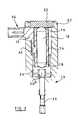
- FIG. 1is a schematic view of an actuator housing for a piezoelectric actuator in accordance with an embodiment of the present invention.
- FIG. 2is a schematic view of a fuel injector including a piezoelectric actuator arranged within the actuator housing shown in FIG. 1 .
- an actuator housingfor a piezoelectric actuator arrangement including a piezoelectric stack 12 , for use in controlling the operation of a valve of a fuel injector, referred to generally as 13 .
- the housing 10includes a sleeve portion 14 within which the piezoelectric stack 12 is located, the piezoelectric stack 12 engaging first and second end members 16 , 18 respectively, each end member 16 , 18 having an end surface projecting through the open ends of the sleeve portion 14 .
- the end members 16 , 18 of the piezoelectric stack 12are made of steel and have an exposed surface of part-spherical form.
- the first end member 16abuts an abutment member 20 which is rigidly fixed to the fuel injector body 22 .
- the second end member 18is engageable with a piston member 24 such that, in use, an increase in the axial length of the piezoelectric stack causes the end member 18 to impart movement to the piston member 24 , the piston member 24 controlling the fluid pressure within a control chamber 24 a which, in turn, controls movement of a spill valve member 26 to control fuel delivery from the fuel injector.
- the end members 16 , 18are of domed, or similar, form such that, during assembly, the stack 12 can adopt a position which need not be exactly parallel to the axis of the injector, thereby compensating for manufacturing tolerances.
- the piezoelectric stack 12is provided with connecting leads 28 , one end of each lead 28 being connected to the stack 12 and the other end of each lead 28 being connected to an electrical connector 30 at electrical terminals 32 .
- the connector 30 and the terminals 32are housed within a connector housing portion 34 which is integrally formed with a flexible neck portion 36 of the housing 10 and with the sleeve portion 14 .
- the connecting leads 28are arranged within the neck portion 36 such that, during assembly and use of the fuel injector 13 , a degree of flexing of the connecting leads 28 is permitted.
- the housing 10therefore forms a three-part housing for the piezoelectric stack 12 , the connecting leads 28 , and the electrical connector 30 comprising the sleeve portion 14 , the flexible neck portion 36 and the connector housing portion 34 .
- the housing 10may be formed from a polymer material using conventional injection moulding techniques, conveniently using a single shot technique. During manufacture of the housing 10 , the end cap members 16 , 18 may be supported in the injection moulding die such that they remain free from polymer material which may otherwise reduce axial stiffness of the piezoelectric stack 12 .
- the material from which the housing 10 is formedmay be a polymer having mechanical properties similar to those of Nylon at room temperature, but with better thermal and chemical resistances. For example, a liquid crystal polymer material may be used.
- the connecting portion 34 housing the electrical connectorcan be clamped robustly into the fuel injector body 22 without causing damage to the connecting leads 28 or the piezoelectric stack 12 during assembly of the fuel injector 13 , for example resulting from the stack lying not exactly parallel to the axis of the injector.
- any displacement of the piezoelectric stack 12 during its service life due to wear of the surfaces of the end cap members 16 , 18 , or due to thermal expansion effectsdoes not result in damage being caused to the connecting leads 28 or the electrical terminals 32 as the connecting leads 28 and the neck portion 36 are able to flex.
- the actuator housing 10also provides the advantage that the electrical terminals 32 are sealed within the connector housing part 34 during moulding of the housing 10 . Thus, additional seals at the electrical terminals need not be provided.
- the sleeve portion 14conveniently forms a substantially fluid tight seal with the end cap members 16 , 18 , thus isolating the stack 12 and the associated leads and electrical connections from fuel or other fluids.
- the connector housing portion 34need not form part of the housing 10 for the actuator, the connecting leads 28 , moulded within the flexible neck portion 36 , projecting from the housing 10 for connection with electrical terminals of an external electrical connector.
- the flexible neck portion 36may join the sleeve portion 14 close to the end of the sleeve portion 14 housing the end member 16 , the position of which is fixed, in use, thereby reducing the degree by which the neck portion 36 must flex in use.
Landscapes
- Engineering & Computer Science (AREA)
- Chemical & Material Sciences (AREA)
- Combustion & Propulsion (AREA)
- Mechanical Engineering (AREA)
- General Engineering & Computer Science (AREA)
- Physics & Mathematics (AREA)
- Fluid Mechanics (AREA)
- Fuel-Injection Apparatus (AREA)
- General Electrical Machinery Utilizing Piezoelectricity, Electrostriction Or Magnetostriction (AREA)
- Lens Barrels (AREA)
- Valve Device For Special Equipments (AREA)
- Input Circuits Of Receivers And Coupling Of Receivers And Audio Equipment (AREA)
Abstract
Description
Claims (7)
Applications Claiming Priority (2)
| Application Number | Priority Date | Filing Date | Title |
|---|---|---|---|
| GB9919661 | 1999-08-20 | ||
| GBGB9919661.0AGB9919661D0 (en) | 1999-08-20 | 1999-08-20 | Actuator housing |
Publications (1)
| Publication Number | Publication Date |
|---|---|
| US6359373B1true US6359373B1 (en) | 2002-03-19 |
Family
ID=10859451
Family Applications (1)
| Application Number | Title | Priority Date | Filing Date |
|---|---|---|---|
| US09/639,571Expired - LifetimeUS6359373B1 (en) | 1999-08-20 | 2000-08-14 | Actuator housing |
Country Status (5)
| Country | Link |
|---|---|
| US (1) | US6359373B1 (en) |
| EP (1) | EP1079097B1 (en) |
| AT (1) | ATE263922T1 (en) |
| DE (1) | DE60009613T2 (en) |
| GB (1) | GB9919661D0 (en) |
Cited By (12)
| Publication number | Priority date | Publication date | Assignee | Title |
|---|---|---|---|---|
| US6661159B2 (en)* | 2001-07-18 | 2003-12-09 | Denso Corporation | Construction for transmitting displacement of piezoelectric element |
| US20040084999A1 (en)* | 2002-01-23 | 2004-05-06 | Tdk Corporation | Piezoelectric sensor |
| US20050046310A1 (en)* | 2000-05-31 | 2005-03-03 | Denso Corporation | Piezoelectric device for injector |
| WO2007119174A3 (en)* | 2006-02-14 | 2008-01-17 | Delphi Tech Inc | Piezoelectric actuator |
| CN100376784C (en)* | 2003-01-24 | 2008-03-26 | 西门子Vdo汽车公司 | Metering device for the metered supply of a pressurized fluid |
| CN100459203C (en)* | 2003-10-14 | 2009-02-04 | 西门子公司 | Receiving sleeve for an actuator body |
| US20090199379A1 (en)* | 2006-06-06 | 2009-08-13 | Albano De Paoli | Arrangement with a coated piezoelectric actuator |
| US20100187329A1 (en)* | 2007-06-27 | 2010-07-29 | Renault S.A.S. | Fluid injection device |
| US20100308693A1 (en)* | 2009-06-04 | 2010-12-09 | Phillips James R | Piezoelectric Stack Actuator Assembly |
| CN1906388B (en)* | 2003-12-31 | 2011-04-06 | 安费诺有限公司 | Fuel injector connector |
| CN1867763B (en)* | 2003-10-14 | 2012-01-11 | 欧陆汽车有限责任公司 | Piezoelectric actuator and associated production method |
| CN102472213A (en)* | 2009-07-21 | 2012-05-23 | 埃普科斯股份有限公司 | Piezoelectric actuator with electrical contact |
Families Citing this family (4)
| Publication number | Priority date | Publication date | Assignee | Title |
|---|---|---|---|---|
| EP1445470A1 (en)* | 2003-01-24 | 2004-08-11 | Siemens VDO Automotive S.p.A. | Metering device with an electrical connector |
| DE102005016461A1 (en)* | 2005-04-11 | 2006-10-12 | Robert Bosch Gmbh | Fuel injection valve for internal combustion engine, has actuator electrically contacted by electrical conductors that are fixed at bearing points, where one electrical conductor provided between bearing points has cable cleat |
| EP1783842B1 (en) | 2005-11-04 | 2008-03-05 | Delphi Technologies, Inc. | Actuator arrangement |
| CN113315412B (en)* | 2021-06-01 | 2022-12-06 | 上海隐冠半导体技术有限公司 | Piezoelectric ceramic actuator |
Citations (3)
| Publication number | Priority date | Publication date | Assignee | Title |
|---|---|---|---|---|
| US4958101A (en)* | 1988-08-29 | 1990-09-18 | Toyota Jidosha Kabushiki Kaisha | Piezoelectric actuator |
| US5208506A (en)* | 1990-11-14 | 1993-05-04 | Nec Corporation | Laminated piezoelectric actuator |
| US6198206B1 (en)* | 1998-03-20 | 2001-03-06 | Active Control Experts, Inc. | Inertial/audio unit and construction |
Family Cites Families (3)
| Publication number | Priority date | Publication date | Assignee | Title |
|---|---|---|---|---|
| DE4003228A1 (en)* | 1990-02-03 | 1991-08-22 | Bosch Gmbh Robert | ELECTROMAGNETICALLY ACTUABLE VALVE |
| DE19715487C2 (en)* | 1997-04-14 | 2002-06-13 | Siemens Ag | Piezoelectric actuator with a hollow profile |
| JPH1187011A (en)* | 1997-09-03 | 1999-03-30 | Yazaki Corp | Connector molding method |
- 1999
- 1999-08-20GBGBGB9919661.0Apatent/GB9919661D0/ennot_activeCeased
- 2000
- 2000-08-09DEDE60009613Tpatent/DE60009613T2/ennot_activeExpired - Lifetime
- 2000-08-09EPEP00306809Apatent/EP1079097B1/ennot_activeExpired - Lifetime
- 2000-08-09ATAT00306809Tpatent/ATE263922T1/ennot_activeIP Right Cessation
- 2000-08-14USUS09/639,571patent/US6359373B1/ennot_activeExpired - Lifetime
Patent Citations (3)
| Publication number | Priority date | Publication date | Assignee | Title |
|---|---|---|---|---|
| US4958101A (en)* | 1988-08-29 | 1990-09-18 | Toyota Jidosha Kabushiki Kaisha | Piezoelectric actuator |
| US5208506A (en)* | 1990-11-14 | 1993-05-04 | Nec Corporation | Laminated piezoelectric actuator |
| US6198206B1 (en)* | 1998-03-20 | 2001-03-06 | Active Control Experts, Inc. | Inertial/audio unit and construction |
Cited By (18)
| Publication number | Priority date | Publication date | Assignee | Title |
|---|---|---|---|---|
| US20050046310A1 (en)* | 2000-05-31 | 2005-03-03 | Denso Corporation | Piezoelectric device for injector |
| US7067960B2 (en)* | 2000-05-31 | 2006-06-27 | Denso Corporation | Piezoelectric device for injector |
| US6661159B2 (en)* | 2001-07-18 | 2003-12-09 | Denso Corporation | Construction for transmitting displacement of piezoelectric element |
| US20040084999A1 (en)* | 2002-01-23 | 2004-05-06 | Tdk Corporation | Piezoelectric sensor |
| US6800986B2 (en)* | 2002-01-23 | 2004-10-05 | Tdk Corporation | Piezoelectric sensor |
| CN100376784C (en)* | 2003-01-24 | 2008-03-26 | 西门子Vdo汽车公司 | Metering device for the metered supply of a pressurized fluid |
| CN1867763B (en)* | 2003-10-14 | 2012-01-11 | 欧陆汽车有限责任公司 | Piezoelectric actuator and associated production method |
| CN100459203C (en)* | 2003-10-14 | 2009-02-04 | 西门子公司 | Receiving sleeve for an actuator body |
| CN1906388B (en)* | 2003-12-31 | 2011-04-06 | 安费诺有限公司 | Fuel injector connector |
| US20100264780A1 (en)* | 2006-02-14 | 2010-10-21 | Kiefer Joachim R | Piezoelectric Actuator |
| US8022603B2 (en)* | 2006-02-14 | 2011-09-20 | Delphi Technologies Holding S.Arl | Piezoelectric actuator |
| WO2007119174A3 (en)* | 2006-02-14 | 2008-01-17 | Delphi Tech Inc | Piezoelectric actuator |
| US20090199379A1 (en)* | 2006-06-06 | 2009-08-13 | Albano De Paoli | Arrangement with a coated piezoelectric actuator |
| US7990023B2 (en)* | 2006-06-06 | 2011-08-02 | Robert Bosch Gmbh | Arrangement with a coated piezoelectric actuator |
| US20100187329A1 (en)* | 2007-06-27 | 2010-07-29 | Renault S.A.S. | Fluid injection device |
| US20100308693A1 (en)* | 2009-06-04 | 2010-12-09 | Phillips James R | Piezoelectric Stack Actuator Assembly |
| CN102472213A (en)* | 2009-07-21 | 2012-05-23 | 埃普科斯股份有限公司 | Piezoelectric actuator with electrical contact |
| CN102472213B (en)* | 2009-07-21 | 2015-07-15 | 埃普科斯股份有限公司 | Piezo actuator with electrical contacts |
Also Published As
| Publication number | Publication date |
|---|---|
| EP1079097B1 (en) | 2004-04-07 |
| ATE263922T1 (en) | 2004-04-15 |
| EP1079097A2 (en) | 2001-02-28 |
| DE60009613D1 (en) | 2004-05-13 |
| DE60009613T2 (en) | 2005-03-17 |
| GB9919661D0 (en) | 1999-10-20 |
| EP1079097A3 (en) | 2003-01-08 |
Similar Documents
| Publication | Publication Date | Title |
|---|---|---|
| US6359373B1 (en) | Actuator housing | |
| US6274967B1 (en) | Piezoelectric actuator for a servo drive, servo drive with a piezoelectric actuator and method of producing a piezoelectric actuator | |
| US7097484B2 (en) | Sealing element for the piezo actuator of a fuel injection valve | |
| US7728489B2 (en) | Piezoelectric actuator with a sheath, for disposition in a piezoelectric injector | |
| CN1175179C (en) | fuel injection valve | |
| US6474565B1 (en) | Fuel injection valve | |
| US20050247803A1 (en) | Fuel injector | |
| US6814314B1 (en) | Fuel injection valve | |
| CN100508234C (en) | fuel injector with electrical connector | |
| JPH04279756A (en) | Contacting strip for electrically interconnecting touchably plurality of units being energized electrically in internal combustion engine | |
| US7032833B2 (en) | Fuel injection valve | |
| US20080202477A1 (en) | Fuel Injection Valve | |
| US6899284B1 (en) | Fuel-injection valve | |
| KR20050021538A (en) | Piezoelectirc actuator module and method for assembling a piezoelectric actuator module | |
| US20110006137A1 (en) | Sealed electric feedthrough | |
| US6543702B1 (en) | Fuel injection valve | |
| US6425376B1 (en) | Fuel injector | |
| US20090260598A1 (en) | Arrangement with a piezoelectric actuator around which fluid media flow | |
| US7422006B2 (en) | Fuel injector | |
| US8038079B2 (en) | Injection system and a method for producing an injection system | |
| JP2009506735A (en) | Assembly with piezo actuator | |
| US6517046B1 (en) | Fuel injection valve | |
| US7063278B2 (en) | Fuel injection valve | |
| KR20020061590A (en) | Valve for controlling liquids | |
| KR20040091753A (en) | Fuel injection valve |
Legal Events
| Date | Code | Title | Description |
|---|---|---|---|
| AS | Assignment | Owner name:DELPHI TECHNOLOGIES, INC., MICHIGAN Free format text:ASSIGNMENT OF ASSIGNORS INTEREST;ASSIGNORS:BUCKLEY, PAUL;COOKE, MICHAEL PETER;REEL/FRAME:011382/0157 Effective date:20000830 | |
| STCF | Information on status: patent grant | Free format text:PATENTED CASE | |
| AS | Assignment | Owner name:JPMORGAN CHASE BANK, N.A., TEXAS Free format text:SECURITY AGREEMENT;ASSIGNOR:DELPHI TECHNOLOGIES, INC.;REEL/FRAME:016237/0402 Effective date:20050614 | |
| FPAY | Fee payment | Year of fee payment:4 | |
| AS | Assignment | Owner name:DELPHI TECHNOLOGIES, INC., MICHIGAN Free format text:RELEASE OF SECURITY AGREEMENT;ASSIGNOR:JPMORGAN CHASE BANK, N.A.;REEL/FRAME:020808/0583 Effective date:20080225 | |
| FPAY | Fee payment | Year of fee payment:8 | |
| AS | Assignment | Owner name:DELPHI TECHNOLOGIES HOLDING S.ARL,LUXEMBOURG Free format text:ASSIGNMENT OF ASSIGNORS INTEREST;ASSIGNOR:DELPHI TECHNOLOGIES, INC.;REEL/FRAME:024233/0854 Effective date:20100406 Owner name:DELPHI TECHNOLOGIES HOLDING S.ARL, LUXEMBOURG Free format text:ASSIGNMENT OF ASSIGNORS INTEREST;ASSIGNOR:DELPHI TECHNOLOGIES, INC.;REEL/FRAME:024233/0854 Effective date:20100406 | |
| FPAY | Fee payment | Year of fee payment:12 | |
| AS | Assignment | Owner name:DELPHI INTERNATIONAL OPERATIONS LUXEMBOURG S.A.R.L Free format text:MERGER;ASSIGNOR:DELPHI TECHNOLOGIES HOLDING S.ARL;REEL/FRAME:032227/0343 Effective date:20140116 | |
| AS | Assignment | Owner name:DELPHI TECHNOLOGIES IP LIMITED, BARBADOS Free format text:ASSIGNMENT OF ASSIGNORS INTEREST;ASSIGNOR:DELPHI INTERNATIONAL OPERATIONS LUXEMBOURG S.A.R.L.;REEL/FRAME:045081/0502 Effective date:20171129 |