US6358271B1 - Fused loop of filamentous material and apparatus for making same - Google Patents
Fused loop of filamentous material and apparatus for making sameDownload PDFInfo
- Publication number
- US6358271B1 US6358271B1US09/486,760US48676000AUS6358271B1US 6358271 B1US6358271 B1US 6358271B1US 48676000 AUS48676000 AUS 48676000AUS 6358271 B1US6358271 B1US 6358271B1
- Authority
- US
- United States
- Prior art keywords
- fused
- loop
- portions
- elongated material
- joint region
- Prior art date
- Legal status (The legal status is an assumption and is not a legal conclusion. Google has not performed a legal analysis and makes no representation as to the accuracy of the status listed.)
- Expired - Lifetime
Links
- 239000000463materialSubstances0.000titleclaimsabstractdescription152
- 238000003466weldingMethods0.000claimsabstractdescription55
- 239000003356suture materialSubstances0.000claimsdescription13
- 230000000295complement effectEffects0.000claimsdescription9
- 230000008859changeEffects0.000claimsdescription6
- 230000000737periodic effectEffects0.000claimsdescription4
- 238000010891electric arcMethods0.000claimsdescription3
- 239000012815thermoplastic materialSubstances0.000claimsdescription2
- 238000000034methodMethods0.000abstractdescription22
- 230000008569processEffects0.000abstractdescription20
- 230000008878couplingEffects0.000description6
- 238000010168coupling processMethods0.000description6
- 238000005859coupling reactionMethods0.000description6
- 238000010438heat treatmentMethods0.000description4
- 239000004033plasticSubstances0.000description4
- 229920003023plasticPolymers0.000description4
- 230000035876healingEffects0.000description3
- 229920000642polymerPolymers0.000description3
- 229920000954PolyglycolidePolymers0.000description2
- 230000007423decreaseEffects0.000description2
- 230000004927fusionEffects0.000description2
- 238000011065in-situ storageMethods0.000description2
- 239000004633polyglycolic acidSubstances0.000description2
- -1polypropylenePolymers0.000description2
- 230000008439repair processEffects0.000description2
- 238000001356surgical procedureMethods0.000description2
- 229920004934Dacron®Polymers0.000description1
- 239000004677NylonSubstances0.000description1
- 239000004952PolyamideSubstances0.000description1
- 239000004743PolypropyleneSubstances0.000description1
- 230000009471actionEffects0.000description1
- 230000008901benefitEffects0.000description1
- 239000002131composite materialSubstances0.000description1
- 230000006835compressionEffects0.000description1
- 238000007906compressionMethods0.000description1
- 230000003247decreasing effectEffects0.000description1
- 230000000694effectsEffects0.000description1
- 238000001125extrusionMethods0.000description1
- 239000012530fluidSubstances0.000description1
- 230000007794irritationEffects0.000description1
- 238000002844meltingMethods0.000description1
- 230000008018meltingEffects0.000description1
- 229920001778nylonPolymers0.000description1
- 210000000056organAnatomy0.000description1
- 229920002463poly(p-dioxanone) polymerPolymers0.000description1
- 229920002647polyamidePolymers0.000description1
- 239000000622polydioxanoneSubstances0.000description1
- 229920000728polyesterPolymers0.000description1
- 229920001155polypropylenePolymers0.000description1
- 238000002360preparation methodMethods0.000description1
- 229920001169thermoplasticPolymers0.000description1
Images


Classifications
- B—PERFORMING OPERATIONS; TRANSPORTING
- B29—WORKING OF PLASTICS; WORKING OF SUBSTANCES IN A PLASTIC STATE IN GENERAL
- B29C—SHAPING OR JOINING OF PLASTICS; SHAPING OF MATERIAL IN A PLASTIC STATE, NOT OTHERWISE PROVIDED FOR; AFTER-TREATMENT OF THE SHAPED PRODUCTS, e.g. REPAIRING
- B29C65/00—Joining or sealing of preformed parts, e.g. welding of plastics materials; Apparatus therefor
- B29C65/02—Joining or sealing of preformed parts, e.g. welding of plastics materials; Apparatus therefor by heating, with or without pressure
- B29C65/08—Joining or sealing of preformed parts, e.g. welding of plastics materials; Apparatus therefor by heating, with or without pressure using ultrasonic vibrations
- A—HUMAN NECESSITIES
- A61—MEDICAL OR VETERINARY SCIENCE; HYGIENE
- A61B—DIAGNOSIS; SURGERY; IDENTIFICATION
- A61B17/00—Surgical instruments, devices or methods
- A61B17/04—Surgical instruments, devices or methods for suturing wounds; Holders or packages for needles or suture materials
- A61B17/0487—Suture clamps, clips or locks, e.g. for replacing suture knots; Instruments for applying or removing suture clamps, clips or locks
- A—HUMAN NECESSITIES
- A61—MEDICAL OR VETERINARY SCIENCE; HYGIENE
- A61B—DIAGNOSIS; SURGERY; IDENTIFICATION
- A61B17/00—Surgical instruments, devices or methods
- A61B17/04—Surgical instruments, devices or methods for suturing wounds; Holders or packages for needles or suture materials
- A61B17/06—Needles ; Sutures; Needle-suture combinations; Holders or packages for needles or suture materials
- A61B17/06166—Sutures
- A—HUMAN NECESSITIES
- A61—MEDICAL OR VETERINARY SCIENCE; HYGIENE
- A61L—METHODS OR APPARATUS FOR STERILISING MATERIALS OR OBJECTS IN GENERAL; DISINFECTION, STERILISATION OR DEODORISATION OF AIR; CHEMICAL ASPECTS OF BANDAGES, DRESSINGS, ABSORBENT PADS OR SURGICAL ARTICLES; MATERIALS FOR BANDAGES, DRESSINGS, ABSORBENT PADS OR SURGICAL ARTICLES
- A61L17/00—Materials for surgical sutures or for ligaturing blood vessels ; Materials for prostheses or catheters
- B—PERFORMING OPERATIONS; TRANSPORTING
- B29—WORKING OF PLASTICS; WORKING OF SUBSTANCES IN A PLASTIC STATE IN GENERAL
- B29C—SHAPING OR JOINING OF PLASTICS; SHAPING OF MATERIAL IN A PLASTIC STATE, NOT OTHERWISE PROVIDED FOR; AFTER-TREATMENT OF THE SHAPED PRODUCTS, e.g. REPAIRING
- B29C66/00—General aspects of processes or apparatus for joining preformed parts
- B29C66/01—General aspects dealing with the joint area or with the area to be joined
- B29C66/05—Particular design of joint configurations
- B29C66/10—Particular design of joint configurations particular design of the joint cross-sections
- B29C66/11—Joint cross-sections comprising a single joint-segment, i.e. one of the parts to be joined comprising a single joint-segment in the joint cross-section
- B29C66/112—Single lapped joints
- B29C66/1122—Single lap to lap joints, i.e. overlap joints
- B—PERFORMING OPERATIONS; TRANSPORTING
- B29—WORKING OF PLASTICS; WORKING OF SUBSTANCES IN A PLASTIC STATE IN GENERAL
- B29C—SHAPING OR JOINING OF PLASTICS; SHAPING OF MATERIAL IN A PLASTIC STATE, NOT OTHERWISE PROVIDED FOR; AFTER-TREATMENT OF THE SHAPED PRODUCTS, e.g. REPAIRING
- B29C66/00—General aspects of processes or apparatus for joining preformed parts
- B29C66/50—General aspects of joining tubular articles; General aspects of joining long products, i.e. bars or profiled elements; General aspects of joining single elements to tubular articles, hollow articles or bars; General aspects of joining several hollow-preforms to form hollow or tubular articles
- B29C66/51—Joining tubular articles, profiled elements or bars; Joining single elements to tubular articles, hollow articles or bars; Joining several hollow-preforms to form hollow or tubular articles
- B29C66/52—Joining tubular articles, bars or profiled elements
- B29C66/526—Joining bars
- B29C66/5261—Joining bars for forming coaxial connections, i.e. the bars to be joined forming a zero angle relative to each other
- B—PERFORMING OPERATIONS; TRANSPORTING
- B29—WORKING OF PLASTICS; WORKING OF SUBSTANCES IN A PLASTIC STATE IN GENERAL
- B29C—SHAPING OR JOINING OF PLASTICS; SHAPING OF MATERIAL IN A PLASTIC STATE, NOT OTHERWISE PROVIDED FOR; AFTER-TREATMENT OF THE SHAPED PRODUCTS, e.g. REPAIRING
- B29C66/00—General aspects of processes or apparatus for joining preformed parts
- B29C66/69—General aspects of joining filaments
- B—PERFORMING OPERATIONS; TRANSPORTING
- B29—WORKING OF PLASTICS; WORKING OF SUBSTANCES IN A PLASTIC STATE IN GENERAL
- B29C—SHAPING OR JOINING OF PLASTICS; SHAPING OF MATERIAL IN A PLASTIC STATE, NOT OTHERWISE PROVIDED FOR; AFTER-TREATMENT OF THE SHAPED PRODUCTS, e.g. REPAIRING
- B29C66/00—General aspects of processes or apparatus for joining preformed parts
- B29C66/80—General aspects of machine operations or constructions and parts thereof
- B29C66/81—General aspects of the pressing elements, i.e. the elements applying pressure on the parts to be joined in the area to be joined, e.g. the welding jaws or clamps
- B29C66/814—General aspects of the pressing elements, i.e. the elements applying pressure on the parts to be joined in the area to be joined, e.g. the welding jaws or clamps characterised by the design of the pressing elements, e.g. of the welding jaws or clamps
- B29C66/8141—General aspects of the pressing elements, i.e. the elements applying pressure on the parts to be joined in the area to be joined, e.g. the welding jaws or clamps characterised by the design of the pressing elements, e.g. of the welding jaws or clamps characterised by the surface geometry of the part of the pressing elements, e.g. welding jaws or clamps, coming into contact with the parts to be joined
- B29C66/81411—General aspects of the pressing elements, i.e. the elements applying pressure on the parts to be joined in the area to be joined, e.g. the welding jaws or clamps characterised by the design of the pressing elements, e.g. of the welding jaws or clamps characterised by the surface geometry of the part of the pressing elements, e.g. welding jaws or clamps, coming into contact with the parts to be joined characterised by its cross-section, e.g. transversal or longitudinal, being non-flat
- B29C66/81421—General aspects of the pressing elements, i.e. the elements applying pressure on the parts to be joined in the area to be joined, e.g. the welding jaws or clamps characterised by the design of the pressing elements, e.g. of the welding jaws or clamps characterised by the surface geometry of the part of the pressing elements, e.g. welding jaws or clamps, coming into contact with the parts to be joined characterised by its cross-section, e.g. transversal or longitudinal, being non-flat being convex or concave
- B29C66/81422—General aspects of the pressing elements, i.e. the elements applying pressure on the parts to be joined in the area to be joined, e.g. the welding jaws or clamps characterised by the design of the pressing elements, e.g. of the welding jaws or clamps characterised by the surface geometry of the part of the pressing elements, e.g. welding jaws or clamps, coming into contact with the parts to be joined characterised by its cross-section, e.g. transversal or longitudinal, being non-flat being convex or concave being convex
- B—PERFORMING OPERATIONS; TRANSPORTING
- B29—WORKING OF PLASTICS; WORKING OF SUBSTANCES IN A PLASTIC STATE IN GENERAL
- B29C—SHAPING OR JOINING OF PLASTICS; SHAPING OF MATERIAL IN A PLASTIC STATE, NOT OTHERWISE PROVIDED FOR; AFTER-TREATMENT OF THE SHAPED PRODUCTS, e.g. REPAIRING
- B29C66/00—General aspects of processes or apparatus for joining preformed parts
- B29C66/80—General aspects of machine operations or constructions and parts thereof
- B29C66/81—General aspects of the pressing elements, i.e. the elements applying pressure on the parts to be joined in the area to be joined, e.g. the welding jaws or clamps
- B29C66/814—General aspects of the pressing elements, i.e. the elements applying pressure on the parts to be joined in the area to be joined, e.g. the welding jaws or clamps characterised by the design of the pressing elements, e.g. of the welding jaws or clamps
- B29C66/8141—General aspects of the pressing elements, i.e. the elements applying pressure on the parts to be joined in the area to be joined, e.g. the welding jaws or clamps characterised by the design of the pressing elements, e.g. of the welding jaws or clamps characterised by the surface geometry of the part of the pressing elements, e.g. welding jaws or clamps, coming into contact with the parts to be joined
- B29C66/81411—General aspects of the pressing elements, i.e. the elements applying pressure on the parts to be joined in the area to be joined, e.g. the welding jaws or clamps characterised by the design of the pressing elements, e.g. of the welding jaws or clamps characterised by the surface geometry of the part of the pressing elements, e.g. welding jaws or clamps, coming into contact with the parts to be joined characterised by its cross-section, e.g. transversal or longitudinal, being non-flat
- B29C66/81421—General aspects of the pressing elements, i.e. the elements applying pressure on the parts to be joined in the area to be joined, e.g. the welding jaws or clamps characterised by the design of the pressing elements, e.g. of the welding jaws or clamps characterised by the surface geometry of the part of the pressing elements, e.g. welding jaws or clamps, coming into contact with the parts to be joined characterised by its cross-section, e.g. transversal or longitudinal, being non-flat being convex or concave
- B29C66/81423—General aspects of the pressing elements, i.e. the elements applying pressure on the parts to be joined in the area to be joined, e.g. the welding jaws or clamps characterised by the design of the pressing elements, e.g. of the welding jaws or clamps characterised by the surface geometry of the part of the pressing elements, e.g. welding jaws or clamps, coming into contact with the parts to be joined characterised by its cross-section, e.g. transversal or longitudinal, being non-flat being convex or concave being concave
- B—PERFORMING OPERATIONS; TRANSPORTING
- B29—WORKING OF PLASTICS; WORKING OF SUBSTANCES IN A PLASTIC STATE IN GENERAL
- B29C—SHAPING OR JOINING OF PLASTICS; SHAPING OF MATERIAL IN A PLASTIC STATE, NOT OTHERWISE PROVIDED FOR; AFTER-TREATMENT OF THE SHAPED PRODUCTS, e.g. REPAIRING
- B29C66/00—General aspects of processes or apparatus for joining preformed parts
- B29C66/80—General aspects of machine operations or constructions and parts thereof
- B29C66/81—General aspects of the pressing elements, i.e. the elements applying pressure on the parts to be joined in the area to be joined, e.g. the welding jaws or clamps
- B29C66/814—General aspects of the pressing elements, i.e. the elements applying pressure on the parts to be joined in the area to be joined, e.g. the welding jaws or clamps characterised by the design of the pressing elements, e.g. of the welding jaws or clamps
- B29C66/8141—General aspects of the pressing elements, i.e. the elements applying pressure on the parts to be joined in the area to be joined, e.g. the welding jaws or clamps characterised by the design of the pressing elements, e.g. of the welding jaws or clamps characterised by the surface geometry of the part of the pressing elements, e.g. welding jaws or clamps, coming into contact with the parts to be joined
- B29C66/81433—General aspects of the pressing elements, i.e. the elements applying pressure on the parts to be joined in the area to be joined, e.g. the welding jaws or clamps characterised by the design of the pressing elements, e.g. of the welding jaws or clamps characterised by the surface geometry of the part of the pressing elements, e.g. welding jaws or clamps, coming into contact with the parts to be joined being toothed, i.e. comprising several teeth or pins, or being patterned
- B—PERFORMING OPERATIONS; TRANSPORTING
- B29—WORKING OF PLASTICS; WORKING OF SUBSTANCES IN A PLASTIC STATE IN GENERAL
- B29C—SHAPING OR JOINING OF PLASTICS; SHAPING OF MATERIAL IN A PLASTIC STATE, NOT OTHERWISE PROVIDED FOR; AFTER-TREATMENT OF THE SHAPED PRODUCTS, e.g. REPAIRING
- B29C66/00—General aspects of processes or apparatus for joining preformed parts
- B29C66/80—General aspects of machine operations or constructions and parts thereof
- B29C66/83—General aspects of machine operations or constructions and parts thereof characterised by the movement of the joining or pressing tools
- B29C66/832—Reciprocating joining or pressing tools
- B29C66/8322—Joining or pressing tools reciprocating along one axis
- A—HUMAN NECESSITIES
- A61—MEDICAL OR VETERINARY SCIENCE; HYGIENE
- A61B—DIAGNOSIS; SURGERY; IDENTIFICATION
- A61B17/00—Surgical instruments, devices or methods
- A61B2017/00526—Methods of manufacturing
- A—HUMAN NECESSITIES
- A61—MEDICAL OR VETERINARY SCIENCE; HYGIENE
- A61B—DIAGNOSIS; SURGERY; IDENTIFICATION
- A61B17/00—Surgical instruments, devices or methods
- A61B17/04—Surgical instruments, devices or methods for suturing wounds; Holders or packages for needles or suture materials
- A61B17/0401—Suture anchors, buttons or pledgets, i.e. means for attaching sutures to bone, cartilage or soft tissue; Instruments for applying or removing suture anchors
- A61B2017/0446—Means for attaching and blocking the suture in the suture anchor
- A61B2017/0454—Means for attaching and blocking the suture in the suture anchor the anchor being crimped or clamped on the suture
- A—HUMAN NECESSITIES
- A61—MEDICAL OR VETERINARY SCIENCE; HYGIENE
- A61B—DIAGNOSIS; SURGERY; IDENTIFICATION
- A61B17/00—Surgical instruments, devices or methods
- A61B17/04—Surgical instruments, devices or methods for suturing wounds; Holders or packages for needles or suture materials
- A61B17/06—Needles ; Sutures; Needle-suture combinations; Holders or packages for needles or suture materials
- A61B17/06166—Sutures
- A61B2017/0619—Sutures thermoplastic, e.g. for bonding, welding, fusing or cutting the suture by melting it
- B—PERFORMING OPERATIONS; TRANSPORTING
- B29—WORKING OF PLASTICS; WORKING OF SUBSTANCES IN A PLASTIC STATE IN GENERAL
- B29C—SHAPING OR JOINING OF PLASTICS; SHAPING OF MATERIAL IN A PLASTIC STATE, NOT OTHERWISE PROVIDED FOR; AFTER-TREATMENT OF THE SHAPED PRODUCTS, e.g. REPAIRING
- B29C66/00—General aspects of processes or apparatus for joining preformed parts
- B29C66/70—General aspects of processes or apparatus for joining preformed parts characterised by the composition, physical properties or the structure of the material of the parts to be joined; Joining with non-plastics material
- B29C66/71—General aspects of processes or apparatus for joining preformed parts characterised by the composition, physical properties or the structure of the material of the parts to be joined; Joining with non-plastics material characterised by the composition of the plastics material of the parts to be joined
- B—PERFORMING OPERATIONS; TRANSPORTING
- B29—WORKING OF PLASTICS; WORKING OF SUBSTANCES IN A PLASTIC STATE IN GENERAL
- B29C—SHAPING OR JOINING OF PLASTICS; SHAPING OF MATERIAL IN A PLASTIC STATE, NOT OTHERWISE PROVIDED FOR; AFTER-TREATMENT OF THE SHAPED PRODUCTS, e.g. REPAIRING
- B29C66/00—General aspects of processes or apparatus for joining preformed parts
- B29C66/70—General aspects of processes or apparatus for joining preformed parts characterised by the composition, physical properties or the structure of the material of the parts to be joined; Joining with non-plastics material
- B29C66/73—General aspects of processes or apparatus for joining preformed parts characterised by the composition, physical properties or the structure of the material of the parts to be joined; Joining with non-plastics material characterised by the intensive physical properties of the material of the parts to be joined, by the optical properties of the material of the parts to be joined, by the extensive physical properties of the parts to be joined, by the state of the material of the parts to be joined or by the material of the parts to be joined being a thermoplastic or a thermoset
- B29C66/739—General aspects of processes or apparatus for joining preformed parts characterised by the composition, physical properties or the structure of the material of the parts to be joined; Joining with non-plastics material characterised by the intensive physical properties of the material of the parts to be joined, by the optical properties of the material of the parts to be joined, by the extensive physical properties of the parts to be joined, by the state of the material of the parts to be joined or by the material of the parts to be joined being a thermoplastic or a thermoset characterised by the material of the parts to be joined being a thermoplastic or a thermoset
- B29C66/7392—General aspects of processes or apparatus for joining preformed parts characterised by the composition, physical properties or the structure of the material of the parts to be joined; Joining with non-plastics material characterised by the intensive physical properties of the material of the parts to be joined, by the optical properties of the material of the parts to be joined, by the extensive physical properties of the parts to be joined, by the state of the material of the parts to be joined or by the material of the parts to be joined being a thermoplastic or a thermoset characterised by the material of the parts to be joined being a thermoplastic or a thermoset characterised by the material of at least one of the parts being a thermoplastic
- B29C66/73921—General aspects of processes or apparatus for joining preformed parts characterised by the composition, physical properties or the structure of the material of the parts to be joined; Joining with non-plastics material characterised by the intensive physical properties of the material of the parts to be joined, by the optical properties of the material of the parts to be joined, by the extensive physical properties of the parts to be joined, by the state of the material of the parts to be joined or by the material of the parts to be joined being a thermoplastic or a thermoset characterised by the material of the parts to be joined being a thermoplastic or a thermoset characterised by the material of at least one of the parts being a thermoplastic characterised by the materials of both parts being thermoplastics
- B—PERFORMING OPERATIONS; TRANSPORTING
- B29—WORKING OF PLASTICS; WORKING OF SUBSTANCES IN A PLASTIC STATE IN GENERAL
- B29C—SHAPING OR JOINING OF PLASTICS; SHAPING OF MATERIAL IN A PLASTIC STATE, NOT OTHERWISE PROVIDED FOR; AFTER-TREATMENT OF THE SHAPED PRODUCTS, e.g. REPAIRING
- B29C66/00—General aspects of processes or apparatus for joining preformed parts
- B29C66/80—General aspects of machine operations or constructions and parts thereof
- B29C66/81—General aspects of the pressing elements, i.e. the elements applying pressure on the parts to be joined in the area to be joined, e.g. the welding jaws or clamps
- B29C66/814—General aspects of the pressing elements, i.e. the elements applying pressure on the parts to be joined in the area to be joined, e.g. the welding jaws or clamps characterised by the design of the pressing elements, e.g. of the welding jaws or clamps
- B29C66/8145—General aspects of the pressing elements, i.e. the elements applying pressure on the parts to be joined in the area to be joined, e.g. the welding jaws or clamps characterised by the design of the pressing elements, e.g. of the welding jaws or clamps characterised by the constructional aspects of the pressing elements, e.g. of the welding jaws or clamps
- B29C66/81463—General aspects of the pressing elements, i.e. the elements applying pressure on the parts to be joined in the area to be joined, e.g. the welding jaws or clamps characterised by the design of the pressing elements, e.g. of the welding jaws or clamps characterised by the constructional aspects of the pressing elements, e.g. of the welding jaws or clamps comprising a plurality of single pressing elements, e.g. a plurality of sonotrodes, or comprising a plurality of single counter-pressing elements, e.g. a plurality of anvils, said plurality of said single elements being suitable for making a single joint
- B—PERFORMING OPERATIONS; TRANSPORTING
- B29—WORKING OF PLASTICS; WORKING OF SUBSTANCES IN A PLASTIC STATE IN GENERAL
- B29K—INDEXING SCHEME ASSOCIATED WITH SUBCLASSES B29B, B29C OR B29D, RELATING TO MOULDING MATERIALS OR TO MATERIALS FOR MOULDS, REINFORCEMENTS, FILLERS OR PREFORMED PARTS, e.g. INSERTS
- B29K2023/00—Use of polyalkenes or derivatives thereof as moulding material
- B29K2023/10—Polymers of propylene
- B29K2023/12—PP, i.e. polypropylene
- B—PERFORMING OPERATIONS; TRANSPORTING
- B29—WORKING OF PLASTICS; WORKING OF SUBSTANCES IN A PLASTIC STATE IN GENERAL
- B29K—INDEXING SCHEME ASSOCIATED WITH SUBCLASSES B29B, B29C OR B29D, RELATING TO MOULDING MATERIALS OR TO MATERIALS FOR MOULDS, REINFORCEMENTS, FILLERS OR PREFORMED PARTS, e.g. INSERTS
- B29K2067/00—Use of polyesters or derivatives thereof, as moulding material
- B29K2067/04—Polyesters derived from hydroxycarboxylic acids
- B29K2067/043—PGA, i.e. polyglycolic acid or polyglycolide
- B—PERFORMING OPERATIONS; TRANSPORTING
- B29—WORKING OF PLASTICS; WORKING OF SUBSTANCES IN A PLASTIC STATE IN GENERAL
- B29K—INDEXING SCHEME ASSOCIATED WITH SUBCLASSES B29B, B29C OR B29D, RELATING TO MOULDING MATERIALS OR TO MATERIALS FOR MOULDS, REINFORCEMENTS, FILLERS OR PREFORMED PARTS, e.g. INSERTS
- B29K2077/00—Use of PA, i.e. polyamides, e.g. polyesteramides or derivatives thereof, as moulding material
- B—PERFORMING OPERATIONS; TRANSPORTING
- B29—WORKING OF PLASTICS; WORKING OF SUBSTANCES IN A PLASTIC STATE IN GENERAL
- B29K—INDEXING SCHEME ASSOCIATED WITH SUBCLASSES B29B, B29C OR B29D, RELATING TO MOULDING MATERIALS OR TO MATERIALS FOR MOULDS, REINFORCEMENTS, FILLERS OR PREFORMED PARTS, e.g. INSERTS
- B29K2101/00—Use of unspecified macromolecular compounds as moulding material
- B29K2101/12—Thermoplastic materials
- B—PERFORMING OPERATIONS; TRANSPORTING
- B29—WORKING OF PLASTICS; WORKING OF SUBSTANCES IN A PLASTIC STATE IN GENERAL
- B29L—INDEXING SCHEME ASSOCIATED WITH SUBCLASS B29C, RELATING TO PARTICULAR ARTICLES
- B29L2031/00—Other particular articles
- B29L2031/709—Articles shaped in a closed loop, e.g. conveyor belts
- B29L2031/7096—Rings or ring-like articles
- B29L2031/7102—Toroidal articles
Definitions
- the inventionrelates to improvements in sutures and suturing techniques, and more particularly to materials and devices for making high-strength fused suture loops during surgical procedures.
- a monofilamentous sutureis typically used to stitch or secure the edges of tissue together to maintain them in proximity until healing is substantially completed.
- the sutureis generally directed through the portions of the tissue to be joined and formed into a single loop or stitch, which is then knotted or otherwise secured in order to maintain the wound edges in the appropriate relationship to each other for healing to occur.
- a series of stitches of substantially uniform tensioncan be made in tissue. Because the stitches are individual and separate, the removal of one stitch does not require removal of them all or cause the remaining stitches to loosen. However, each individual stitch requires an individual knot or some other stitch-closing device for securing the stitch around the wound.
- a fused suture loopmust provide the appropriate tension on the wound edges and the appropriate strength to maintain the wound edges in sufficient proximity for a sufficient time to allow healing to occur.
- Polymer suturesare particularly amenable to various fusing or joining processes, such as, for example, welding, whereby sections of the sutures can be fused together upon application of sufficient heat to the sections to cause partial melting and fusion of the sections.
- non-thermal energymay be effectively applied to sections of suture materials to induce frictional heating of the sections in order to fuse or weld them together.
- suture weldsWhile sutures typically fail under tensile loads applied along the principal axis of the suture, suture welds often fail in shear, i.e., in the plane of the fused region between the overlapped segments of suture material. It is desirable to have the failure strength of the suture joint be at least as great as the failure strength of the suture material away from the joint.
- U.S. Pat. No. 5,417,700 to Egan and U.S. Pat. No. 3,515,848 to Winston et al.disclose apparatus and methods for ultrasonic welding of sutures.
- the Winston et al. patentdiscloses, for example, the application of mechanical energy to a segment of material to be joined in either of two different directions. For joining plastic suture materials, mechanical energy is applied in a direction substantially parallel to the axis of the segments to be joined. For joining metallic suture materials, mechanical energy is applied in a direction substantially normal to this axis.
- the Winston et al. patentfurther discloses the use of a spherical welding tip for use in joining metallic suture materials.
- the present inventionprovides a fused loop of an elongated material, such as a polymeric or monofilamentous suture material, which has a strength in the joint region which is at least equal to, if not greater than, the strength of the parent material.
- the present inventionalso provides means for controlling the size and shape of the fused portion of the joint region in order to maximize joint strength.
- a fused loop of an elongated materialcomprising one or more segments of the material which extends along a principal axis. Portions of the segments are joined together to form a loop at a joint region which extends between first and second ends.
- the joint regionincludes a first portion of elongated material extending from the first end, a second portion of elongated material extending from the second end, and a fused portion or layer between and joining the first and second portions at points between the first and second ends of the joint region.
- the fused portionpreferably comprises a relatively thin layer of fused material from the first and second portions.
- fusedrefers to material which has been heated to a plastic or fluid state and subsequently allowed to cool, so that the relatively highly-oriented molecular structure of the parent material is transformed into a relatively randomly-oriented molecular structure characterizing the fused portion of the joint region.
- shear arearefers to the area of the fused portion between and substantially parallel to the segments of material joined in the joint region.
- cross-sectional area of the segments or the fused portionrefers to the area in a plane substantially transverse to the principal axis of the segments.
- the elongated material in the first and second portions of the joint regionis characterized by a relatively high degree of molecular orientation in the direction of the principal axis of the material, and thus relatively high strength in the direction of the principal axis.
- the fused material in the fused portion of the joint regionis characterized by a relatively random molecular orientation, and thus relatively low strength in the direction of the principal axis of the material.
- the cross-sectional area of the first and second portions of the segment at the first and second ends of the joint region, yet outside of (i.e., not abutting) the fused portionis greater than the cross-sectional area of the first and second portions of the joint region which abut the fused portion.
- the cross-sectional area of the first and second portions of the segment at the first and second ends of the joint region, yet outside of the fused portionis approximately equal to the cross-sectional area of a segment of the elongated material outside of the joint region.
- the total cross-sectional area of the first and second portions of the joint region which abut the fused portionis a minimum at approximately the midpoint of the fused portion.
- the total cross-sectional area of the first and second portions of the segment at the midpoint of the fused portionis approximately half the total cross-sectional area of the first and second portions at the first and second ends of the joint region and outside of, or not abutting, the fused portion.
- the change in cross-sectional area of the first and second portions of the segment, per unit length of those portionsis substantially constant over the length of the fused portion of the joint region.
- the elongated materialmay comprise a substantially monofilamentous material, such as, for example, a polymer.
- the elongated materialis a thermoplastic polymer, such as a surgical suture material.
- the segments of elongated materialare preferably joined in a weld at the joint region.
- the weldcan be effected with various types of energy, such as, for example, ultrasonic, laser, electrical arc discharge, and thermal energy.
- the loop of elongated materialcan be made by joining portions of a single segment of the elongated material.
- the loopcan be made by joining portions of multiple segments of the material.
- the elongated materialitself can comprise a single strand of a substantially monofilamentous material.
- the elongated materialcan comprise multiple strands of a substantially monofilamentous material which can be twisted, braided or otherwise interlinked.
- the first and second portions of the joint regionare loaded substantially in tension, and the fused portion of the joint region is loaded substantially in shear.
- a wis the shear area of the fused portion
- ⁇ fwis the shear stress to failure of the fused portion
- a uis the total cross-sectional area of the first and second portions near the first and second ends of the joint region and outside of (not abutting) the fused portion
- ⁇ fuis the tensile stress to failure of the first and second portions near the first and second ends and outside of (not abutting) the fused portion.
- an ultrasonic welding apparatuswhich includes a first member having a first suture-contacting surface, a second member having a second suture-contacting surface, and means for moving the first member relative to the second member to define a gap between the respective suture-contacting surfaces.
- the first memberis capable of vibrating and delivering mechanical energy at ultrasonic frequencies.
- the second memberis stationary relative to the first member.
- a fixture elementis adapted to receive and maintain two or more segments of a material to be welded in a predetermined alignment in the gap between the first and second surfaces of the first and second members during a welding operation.
- the contour of at least the first surfacesubstantially corresponds to the contour of a segment of the material to be welded so as to promote acoustic coupling therebetween and establish substantially continuous contact between the first surface and the segment over the length of the first surface.
- one of the first and second surfacesis substantially convex and the other of the surfaces is substantially concave. In another embodiment, one of the first and second surfaces is substantially convex or substantially concave, and the other of the surfaces is substantially flat. In yet another embodiment, both of the first and second surfaces are substantially convex. In still another embodiment, both of the surfaces are substantially flat.
- the radius of curvature of the convex suture-contacting surfaceis preferably not greater than the radius of curvature of the concave suture-contacting surface.
- the respective radii of curvature of the convex surfacescan be different, or they can be substantially identical.
- the second membercomprises a plurality of coupling portions which couple together to form the second surface during a welding process and separate after completion of the welding process to release the loop.
- an ultrasonic welding apparatusas described above includes first and second members with patterned first and second suture-contacting surfaces.
- the patterned surfacescan be complementary or non-complementary, and the surface patterns on each member may vary in either a periodic or an aperiodic manner.
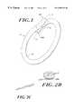
- FIG. 1is a perspective view of a fused loop of an elongated material
- FIG. 2Ais an axial view of the fused loop of FIG. 1;
- FIG. 2Bis an axial view of several fused loops formed by joining multiple segments of material together;
- FIG. 2Cis a simplified perspective view of a multiple-stranded segment of elongated material
- FIG. 3is a cross-sectional view of the joint region of the fused loop of FIG. 2A, taken along section lines A—A;
- FIG. 4is a cross-sectional view of the joint region of the fused loop of FIG. 2A, taken along section lines B—B;
- FIG. 5is a cross-sectional view of an end of the joint region of the fused loop of FIG. 2A, taken along section lines C—C;
- FIG. 6is a cross-sectional view of a segment of elongated material in the fused loop of FIG. 2A, taken along section lines D—D;
- FIG. 7Ais a side elevational view of a joint region of a fused loop made by ultrasonic welding
- FIG. 7Bis a series of sectional views of a portion of the joint region of the loop shown in FIG. 7A;
- FIG. 8Ais a side elevational view of a joint region of a different type of fused loop made by laser welding or controlled coupling ultrasonic welding;
- FIG. 8Bis a series of sectional views of a portion of the joint region of the loop shown in FIG. 8A;
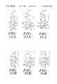
- FIG. 9Ais an axial view of a fused loop loaded in tension, in which the strength of the joint region exceeds the tensile failure strength of the elongated material;
- FIG. 9Bis an axial view of a fused loop loaded in tension, in which the strength of the joint region is less than the tensile failure strength of the elongated material;
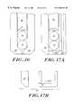
- FIGS. 10A, 11 A, 12 A, 13 A and 14 Aare exploded perspective views of ultrasonic welding members of various geometries, and segments of material to be welded in the gaps between their respective surfaces;
- FIGS. 10B, 11 B, 12 B, 13 B and 14 Bare exploded side elevational views corresponding to the views of FIGS. 10A, 11 A, 12 A, 13 A and 14 A;
- FIGS. 15A, 16 and 17 Aare side elevational views of ultrasonic welding members of various geometries engaged about a pair of segments of material to be welded;
- FIG. 15Bis a simplified side elevational view of the second welding member of FIG. 15A, uncoupled to show means for releasing the welded loop from the welding apparatus;
- FIG. 17Bis a side elevational view of the second welding member of FIG. 17A, uncoupled to show means for releasing the welded loop from the welding apparatus;
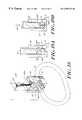
- FIG. 18is an exploded perspective view of a segment of an elongated material with its ends aligned within an ultrasonic welding apparatus designed to produce a contoured lap weld;
- FIG. 19Ais an axial view of the segments of material within the ultrasonic welding apparatus of FIG. 18, prior to welding;
- FIG. 19Bis an axial view of the segments of material within the ultrasonic welding apparatus of FIG. 18, immediately after the welding process and prior to release of the loop;
- FIG. 20is an enlarged perspective view of the fused suture sections of a fused loop, showing the effect of a textured or waffled suture-contacting surface on the welding horn;
- FIG. 21is a cross-sectional view of the fused region of FIG. 20;
- FIG. 22is a side view of a fused loop having a fused region characterized by a complementary waffled pattern on the suture-contacting surfaces of the welding horn and anvil;
- FIG. 23is a side view of a welding horn and anvil with complementary waffled or textured suture-contacting surfaces
- FIG. 24is a side view of the fused region of a portion of a fused loop, in which the loop and fused region are in a relatively relaxed state and the loop has a nominal diameter;
- FIG. 25is a side view of a fused region of a portion of a fused loop, in which the loop and fused region are under tension and the loop has an extended diameter as a result of the expansion of the waffled joint region.
- the present inventionprovides a fused loop of an elongated material, such as a surgical suture.
- the loophas at least comparable strength to knotted loops or loops closed by other means by virtue of the properties of the fused portion of the joint region of the loop, as detailed more fully below.
- the fused loop 10 of the present inventioncomprises one or more segments 12 of an elongated material, such as a surgical suture material or other substantially monofilamentous material, which is amenable to bonding through the application of heat or energy thereto.
- a elongated materialsuch as a surgical suture material or other substantially monofilamentous material, which is amenable to bonding through the application of heat or energy thereto.
- Suitable materials for the elongated materialinclude polymers, especially thermoplastic materials such as, for example, nylon (polyamide), polypropylene, Dacron® (polyester), polyglycolic acid (PGA), polyglyconate, and polydioxanone.
- the fused loop of the present inventionis preferably formed through a welding process, in which segments of the material to be joined are locally heated through the application of energy thereto until the segments fuse together.
- Various types of welded jointscan be formed by the application of, for example, ultrasonic, thermal, laser, electrical arc discharge, or thermal energy to the segments, which can be joined, for example, in an overlapped joint.
- FIG. 2Ais an axial view of the fused loop shown in FIG. 1 .
- the segment 12 of elongated materialextends along a principal axis X of the material, which can be straight or curved.
- One or more segments 12 of the materialare typically formed into a loop by, for example, overlapping portions of the respective ends 12 A, 12 B of the segment, as shown in FIGS. 1 and 2A, to form a joint region 14 .
- both terminal and nonterminal portions of the segments of the materialcan be overlapped to form several fused loops joined in a single joint region 14 .
- the segmentsmay already be knotted in preparation for fusion by welding, or they may simply be overlapped.
- the elongated materialcan be made of a single strand of a substantially monofilamentous material, or it can comprise multiple strands, as indicated in FIG. 2 C.
- the multi-stranded materialcan be twisted, braided or otherwise interlinked to increase the density, and thus the strength, of the composite strand.
- the joint region 14extends between first and second ends 14 A, 14 B and includes a first portion 16 of elongated material extending from the first end 14 A, and a second portion 18 extending from the second end 14 B.
- the joint region 14further includes a fused portion 20 which has a substantially uniform thickness and which is disposed between the first portion 16 and second portion 18 of the joint region.
- the fused portion 20is made of material from the first and second portions 16 , 18 which has been fused together. In a preferred embodiment, all of the fused material is disposed within a fused layer or portion 20 . However, some of the melted and fused material may be extruded outside of the fused portion 20 as a result of forces applied to the segments 16 , 18 to compress them together during the welding process.
- the elongated material of the type used in surgical suturesis substantially monofilamentous, and preferably polymeric. Because the molecular structure of monofilamentous materials is highly oriented along the principal axis of the material, the material exhibits relatively high strength in the direction of its principal axis.
- the elongated material in the loop segment outside the joint region 14 , as well as in the first and second portions 16 , 18 of the joint region,is characterized by a relatively high degree of molecular orientation in the direction of the principal axis X of the material.
- the strength of the elongated material outside the joint region, and in the first and second portions 16 , 18 of the joint region,is also relatively great in the direction of the principal axis X.
- the material which makes up the fused portion 20 of the joint region 14is characterized by a relatively random molecular orientation, by virtue of its having been heated locally to a plastic state by the application of energy, such as ultrasonic energy, to the segment portions 16 , 18 which make up the joint region 14 .
- the strength of the material in the fused portion 20 of the joint regionmay be relatively low in the direction of the principal axis.
- the shear area of the fused portion 20is approximately defined as the product of the length L and the width W of the fused portion 20 , as shown in FIG. 4 . As will be detailed more fully below, for maximum joint strength, it is desirable to have a relatively large shear area of the fused portion 20 of the joint region.
- FIG. 6indicates the cross-sectional area of a typical segment of elongated material outside the joint region.
- the elongated materialcan be a strand or filament having a substantially circular cross-section, the invention is not limited to such geometries and can include elongated materials having eccentric or other cross-sectional geometries, such as, for example, relatively flat ribbons having elliptical or rectangular cross-sections, or others.
- FIG. 5indicates the cross-sectional area of the elongated material at the ends of the joint region, outside of the fused portion 20 . As can be seen in FIGS.
- the total cross-sectional area of the portions 16 , 18 abutting the fused portion 20 of the joint region 14is somewhat less than the total cross-sectional area of the first and second portions 16 , 18 in the joint region but outside of, and not abutting, the fused portion 20 .
- some of the elongated material in portions 16 and 18 of the joint regionis transformed during the welding process from an elongated, relatively highly oriented material, to a fused, relatively randomly-oriented material in the fused portion 20 . Controlled compression of the portions 16 , 18 during the welding process ensures that the fused portion 20 has a relatively large shear area and a relatively small thickness.
- the change in cross-sectional area of the overlapping segments 16 , 18 in the joint regionis preferably uniform and gradual over the length of the fused portion 20 .
- FIGS. 7A, 7 B, 8 A and 8 Billustrate the change in cross-sectional area of the overlapping segments of elongated material in the joint region 14 throughout the length of the fused portion 20 for different types of welded joints.
- the cross-sectional area of the segment portions 16 , 18is a maximum value, as the segment portions have not been caused to deform plastically at these points.
- the cross-hatched areas 21 a - 21 e in the joint region 14indicate in FIG.
- the cross-sectional area of each of the overlapped segment portions 16 , 18decreases gradually from a maximum value at the ends of the fused portion 20 to a minimum value at or near the midpoint of the fused portion.
- the total cross-sectional area of the segments 16 , 18 not sacrificed to form the fused portionis approximately half the total cross-sectional area of the segments 16 , 18 at the first and second ends 14 A, 14 B of the joint region and beyond, or outside of, the fused portion 20 .
- the lap welded joint shown in FIG. 8Ais preferably characterized by a continuously varying cross-sectional area of the segments 16 and 18 in the region of the fused portion 20 .
- the cross-sectional area 21 a - 21 e of one segment 16continuously decreases from a maximum value at end 14 B to a minimum value at the opposite end 14 A, whereas the cross-sectional area of the other segment 18 continuously increases from a minimum value at end 14 B to a maximum value at the opposite end 14 A.
- the cross-sectional areas of the segment portions 16 , 18are preferably approximately equal to each other and are preferably equal to about half the total cross-sectional areas of the segment portions 16 , 18 at the first and second ends 14 A, 14 B of the joint region and outside the fused portion 20 .
- the shear area of the fused portion 20 of the joint regionis sufficiently large to ensure that the joint will not fail prematurely, i.e., before the parent elongated material fails.
- the jointpreferably has a failure strength at least as great as the strength of the parent material. Most preferably, the joint has a failure strength in shear which is greater than or equal to the failure strength in tension of the parent material.
- a wis the shear area of the fused portion 20 (i.e., the area of the layer of the fused portion which is between the first and second portions 16 , 18 , not the cross-sectional area of this layer), ⁇ fw is the shear stress to failure of the fused portion, A u is the total cross-sectional area of the first and second portions 16 , 18 near the first and second ends of the joint region 14 , outside of and not abutting the fused portion, and ⁇ fu is the tensile stress to failure of the first and second portions near the first and second ends, outside of and not abutting the fused portion.
- the strength of the fused portion 20may only be approximately equal to, and possibly less than, the strength of the parent material. It is of course preferred that the fused portion 20 be at least as strong as the unfused parent material. If it is stronger, when the joint is loaded in tension, as indicated by force arrows F in FIGS. 9A and 9B, the material will fail in tensile mode, and the loop will break at a point which is outside the fused portion, and possibly outside the joint region, as indicated in FIG. 9 A. If the fused portion 20 is weaker than the parent material, the fused material within the joint will fail in shear mode, and the loop will separate at the fused portion, as indicated in FIG. 9 B.
- FIGS. 10A-14Billustrate various geometries for ultrasonic welding apparatus, and more particularly for the vibratory and stationary members of an ultrasonic welding tip, which includes a first member 30 and a second member 32 .
- the first member 30is capable of vibrating and delivering mechanical energy at ultrasonic frequencies, as is known in the art.
- the first member 30is movable relative to the second member 32 , so that a gap or space can be defined between the first and second members.
- the gapis sufficiently large to accommodate two or more segments 16 , 18 of material to be joined together.
- the ultrasonic welding apparatusfurther includes a fixture element for aligning and maintaining the segments 16 , 18 in a predetermined alignment and orientation prior to and during the welding process.
- the first and second members 30 , 32each have respective suture-contacting surfaces 30 A, 32 A which are contoured to promote acoustic coupling between the first member 30 and the segment 16 of material to be joined, and to provide substantially continuous contact between at least the first suture-contacting surface 30 A and at least one of the segments to be welded.
- the size of the shear area of the fused portion 20is determined by the length and width of the suture-contacting surfaces 30 A, 32 A, the extent of contact between these surfaces and the segments 16 , 18 , and particularly between the first surface 30 A and the segment 16 closest to the first surface, and the pressure exerted on the segments by the first member 30 in the direction of arrow 35 during welding.
- the geometry of the material to be joinedmust be considered. Fused portions having the largest shear areas and the greatest joint strengths can be obtained by configuring the suture-contacting surfaces 30 A, 32 A of the first and second members to have contours which correspond to the contours of the segments to be joined so as to ensure maximum contact with the segment portions 16 , 18 .
- the materialis a filament having a substantially circular cross-section
- at least one of the suture-contacting surfacesshould preferably have a rounded contour to match the contour of the filament in contact with it.
- the materialis a substantially flat ribbon
- at least one of the suture-contacting surfacesshould preferably be substantially flat to ensure maximum contact with the segment.
- the contour of at least one of the surfacesshould preferably be grooved or channeled or otherwise shaped to correspond as closely as possible to the particular contour of the material.
- the ultrasonic welding tip members 30 , 32It is generally preferred to configure the ultrasonic welding tip members 30 , 32 so that their respective suture-contacting surfaces 30 A, 32 A engage the suture segment portions 16 , 18 so as to provide a maximum shear area for the fused portion 20 .
- Various geometries for the suture-contacting surfaces 30 A, 32 Aare illustrated in FIGS. 10A-14B.
- the suture-contacting surface 30 A of the first member 30is concave about the z and x axes
- the suture-contacting surface 32 A of the second member 32is convex about the z axis.
- the illustrated suture segments 16 , 18have a circular cross-section but need not be limited to a particular geometry. Contact between at least the first surface 30 A and the top segment 16 is substantially continuous over the entire length and width of the surface 30 A as a result of the contour of that surface.
- the shear area of the resulting fused portion 20is relatively large, and thus the strength of the fused portion can be expected to be relatively high.
- An advantage of incorporating a convex curvature to the second suture-contacting surface 32 Ais that the length of the joint region 14 in the direction of the principal axis of the material can be reduced, thereby decreasing the diameter of the resulting fused loop of suture material.
- the radius of curvature of the convex suture-contacting surface 32 Ais preferably equal to or smaller than the radius of curvature of the concave suture-contacting surface 30 A.
- the respective radii of curvature of the convex surfacescan be either different or substantially the same, depending on the desired area of the fused region.
- the suture-contacting surfaces 30 A, 32 A of the embodiment illustrated in FIGS. 14A and 14Bhave the same relationship to each other as in the embodiment of FIGS. 10A and 10B.
- the resulting fused portion 20is relatively large, with relatively high strength.
- the first suture-contacting surface 30 A of the first member 30can have a channeled or grooved geometry to increase the extent of contact between the first suture-contacting surface 30 A and the suture segment 16 .
- the second member 32may be comprised of multiple parts which act to confine and maintain the alignment of the suture segments 16 , 18 during the welding process. The coupling portions of the second member separate after the welding process to release the joined material from the confines of the welding apparatus without requiring the loop to be moved or otherwise manipulated.
- FIGS. 15A, 15 B and 16 Aillustrate one type of ultrasonic welding apparatus, in which the second member 32 couples together beneath the segments of material joined at the joint region. The coupled members remain engaged during the welding process, as shown in FIGS. 15A and 16A, and separate after the welding process by a hinging or pivoting action to release the loop, as shown in FIG. 15 B.
- FIGS. 17A and 17Billustrate another type of apparatus, in which the multiple parts of the second member 32 slide away from each other to release the joined loop.
- Other configurations for the second member 32 which permit the loop to be released after the welding operation is completedare considered to be within the scope of the invention.
- FIGS. 18, 19 A and 19 Billustrate still another configuration for the welding apparatus, in which the suture segments 16 , 18 to be welded are confined and aligned or oriented relative to each other within the walls of the second member 32 .
- This apparatusproduces welded joints having a fused portion 20 in a vertical orientation instead of a horizontal orientation.
- the first member 30is complementary with and fits inside two sections of the second member 32 , which extend vertically on either side of the first member.
- the surfaces 30 A, 32 A of the first and second membersare substantially flat, although they can be cambered and contoured otherwise, as previously discussed. As shown in FIG.
- the overlapping portions 16 , 18 of segment 12 of material to be joined togetherare oriented in a diagonal alignment within the multiple parts of the second member 32 .
- ultrasonic energyis delivered from a power supply and converted to mechanical energy to establish local frictional heating between the segments 16 , 18 .
- Pressureis exerted on the segments 16 , 18 in the direction of arrow 35 as the segments are heated to a plastic state, causing portions of the segments to flow and to fuse in a vertically oriented fused portion 20 .
- the joint region 14 and fused portion 20are relatively dense and compact, with little, if any, fused material disposed in regions outside of the fused portion 20 . It is desirable to minimize the extrusion of fused material beyond the fused portion 20 so as to maximize the strength of the loop joint region and to avoid interference with, or irritation of, the surrounding tissue.
- the coupling portions of the second member 32can be separated after the welding process to release the joined loop.
- FIGS. 20-25illustrate still other embodiments of the invention.
- a fused region 20 of a fused loopis shown with a textured or waffled surface 34 imparted to the suture sections in the joint region from corresponding textured or waffled suture-contacting surfaces on the horn 30 and anvil 32 .
- the waffled surface pattern on the suture-contacting surfaces of the horn and anvilimparts a corresponding waffled pattern on the respective suture sections when the horn and anvil compress the suture segments during a welding process.
- the waffled patternincreases the surface area of the suture sections in the joint region, which may contribute to improved suture weld strength, particularly when the suture loop is under tension.
- the surface patterns on the horn and anvilcan be essentially complementary, as shown in FIG. 23, or they can be non-complementary.
- the patterns in both types of surfacesmay be etched, machined or coined into the material of the horn and anvil and can vary in either a periodic or a non-periodic manner, to provide a desired pattern or texture on the suture sections in the joint region. For example, one might wish to emboss a company logo, serial number or other identifying symbol or code on the suture-contacting surfaces of the horn and anvil so that the resulting fused region of the suture sections includes that identifying mark.
- FIGS. 24 and 25the ability of the fused loop to stretch in tension may be improved by imparting a waffled or otherwise textured pattern to the suture sections in the joint region, thereby producing a joint region which can be expanded or compressed in an accordion fashion.
- FIG. 24illustrates a fused loop having such a joint region, in which the fused suture loop is in a relatively relaxed state and the joint region is not under significant tension.
- the loopwill stretch as the joint region expands in the direction of its principal axis.
- This designmay provide improved flexibility of the fused loop under tension and may contribute to improved strength of the loop. It also allows greater flexibility in the use of fused suture loops, as a certain amount of built-in stretch will allow the loops to expand if necessary rather than break if extended beyond a nominal loop diameter.
Landscapes
- Engineering & Computer Science (AREA)
- Mechanical Engineering (AREA)
- Health & Medical Sciences (AREA)
- Surgery (AREA)
- Life Sciences & Earth Sciences (AREA)
- Animal Behavior & Ethology (AREA)
- Veterinary Medicine (AREA)
- Public Health (AREA)
- General Health & Medical Sciences (AREA)
- Biomedical Technology (AREA)
- Molecular Biology (AREA)
- Medical Informatics (AREA)
- Heart & Thoracic Surgery (AREA)
- Nuclear Medicine, Radiotherapy & Molecular Imaging (AREA)
- Chemical & Material Sciences (AREA)
- Materials Engineering (AREA)
- Vascular Medicine (AREA)
- Epidemiology (AREA)
- Lining Or Joining Of Plastics Or The Like (AREA)
- Materials For Medical Uses (AREA)
Abstract
Description
Claims (25)
Priority Applications (5)
| Application Number | Priority Date | Filing Date | Title |
|---|---|---|---|
| US09/486,760US6358271B1 (en) | 1997-08-28 | 1998-08-27 | Fused loop of filamentous material and apparatus for making same |
| US10/100,213US7090111B2 (en) | 1997-08-28 | 2002-03-18 | Fused loop of filamentous material and apparatus for making same |
| US10/919,933US8197508B2 (en) | 1997-08-28 | 2004-08-17 | Fused loop of filamentous material and apparatus for making same |
| US11/087,995US20050165448A1 (en) | 1997-08-28 | 2005-03-23 | Fused loop of filamentous material and apparatus for making same |
| US11/349,851US20070021780A1 (en) | 1997-08-28 | 2006-06-05 | Multicomponent fused suture loop and apparatus for making same |
Applications Claiming Priority (4)
| Application Number | Priority Date | Filing Date | Title |
|---|---|---|---|
| US08/919,297US5893880A (en) | 1997-08-28 | 1997-08-28 | Fused loop filamentous material |
| US09/118,395US6286746B1 (en) | 1997-08-28 | 1998-07-17 | Fused loop of filamentous material and apparatus for making same |
| US09/486,760US6358271B1 (en) | 1997-08-28 | 1998-08-27 | Fused loop of filamentous material and apparatus for making same |
| PCT/US1998/017770WO1999009891A1 (en) | 1997-08-28 | 1998-08-27 | Fused loop of filamentous material and apparatus for making same |
Related Parent Applications (4)
| Application Number | Title | Priority Date | Filing Date |
|---|---|---|---|
| US08/919,297Continuation-In-PartUS5893880A (en) | 1997-08-28 | 1997-08-28 | Fused loop filamentous material |
| US09/118,395Continuation-In-PartUS6286746B1 (en) | 1997-08-28 | 1998-07-17 | Fused loop of filamentous material and apparatus for making same |
| US09/118,395DivisionUS6286746B1 (en) | 1997-08-28 | 1998-07-17 | Fused loop of filamentous material and apparatus for making same |
| PCT/US1998/017770A-371-Of-InternationalWO1999009891A1 (en) | 1997-08-28 | 1998-08-27 | Fused loop of filamentous material and apparatus for making same |
Related Child Applications (1)
| Application Number | Title | Priority Date | Filing Date |
|---|---|---|---|
| US10/100,213DivisionUS7090111B2 (en) | 1997-08-28 | 2002-03-18 | Fused loop of filamentous material and apparatus for making same |
Publications (1)
| Publication Number | Publication Date |
|---|---|
| US6358271B1true US6358271B1 (en) | 2002-03-19 |
Family
ID=26816303
Family Applications (5)
| Application Number | Title | Priority Date | Filing Date |
|---|---|---|---|
| US09/118,395Expired - LifetimeUS6286746B1 (en) | 1997-08-28 | 1998-07-17 | Fused loop of filamentous material and apparatus for making same |
| US09/486,760Expired - LifetimeUS6358271B1 (en) | 1997-08-28 | 1998-08-27 | Fused loop of filamentous material and apparatus for making same |
| US10/100,213Expired - LifetimeUS7090111B2 (en) | 1997-08-28 | 2002-03-18 | Fused loop of filamentous material and apparatus for making same |
| US10/919,933Expired - Fee RelatedUS8197508B2 (en) | 1997-08-28 | 2004-08-17 | Fused loop of filamentous material and apparatus for making same |
| US11/087,995AbandonedUS20050165448A1 (en) | 1997-08-28 | 2005-03-23 | Fused loop of filamentous material and apparatus for making same |
Family Applications Before (1)
| Application Number | Title | Priority Date | Filing Date |
|---|---|---|---|
| US09/118,395Expired - LifetimeUS6286746B1 (en) | 1997-08-28 | 1998-07-17 | Fused loop of filamentous material and apparatus for making same |
Family Applications After (3)
| Application Number | Title | Priority Date | Filing Date |
|---|---|---|---|
| US10/100,213Expired - LifetimeUS7090111B2 (en) | 1997-08-28 | 2002-03-18 | Fused loop of filamentous material and apparatus for making same |
| US10/919,933Expired - Fee RelatedUS8197508B2 (en) | 1997-08-28 | 2004-08-17 | Fused loop of filamentous material and apparatus for making same |
| US11/087,995AbandonedUS20050165448A1 (en) | 1997-08-28 | 2005-03-23 | Fused loop of filamentous material and apparatus for making same |
Country Status (6)
| Country | Link |
|---|---|
| US (5) | US6286746B1 (en) |
| EP (1) | EP1009288B1 (en) |
| JP (1) | JP4425459B2 (en) |
| AU (1) | AU737903B2 (en) |
| CA (1) | CA2302356C (en) |
| WO (1) | WO1999009891A1 (en) |
Cited By (62)
| Publication number | Priority date | Publication date | Assignee | Title |
|---|---|---|---|---|
| US20030009196A1 (en)* | 2001-06-08 | 2003-01-09 | James Peterson | Suture lock having non-through bore capture zone |
| US20030114864A1 (en)* | 2001-12-18 | 2003-06-19 | Mcrury Ian D. | Suture welding system and method |
| US20030130694A1 (en)* | 1999-12-02 | 2003-07-10 | Ray Bojarski | Soft tissue attachment and repair |
| US20030171763A1 (en)* | 1999-07-13 | 2003-09-11 | Loma Linda University Medical Center | Methods and apparatus for annealing sutures |
| US20030181800A1 (en)* | 2002-03-20 | 2003-09-25 | Bonutti Peter M. | Methods of securing body tissue |
| US20030225438A1 (en)* | 2000-03-13 | 2003-12-04 | Bonutti Peter M. | Method of using ultrasonic vibration to secure body tissue |
| WO2004014217A3 (en)* | 2002-08-09 | 2004-03-18 | Marchitto Kevin | Activated surgical fasteners, devices therefor and uses thereof |
| US20040153074A1 (en)* | 2003-02-05 | 2004-08-05 | Bojarski Raymond A. | Tissue anchor and insertion tool |
| US20040220616A1 (en)* | 2000-03-13 | 2004-11-04 | Bonutti Peter M. | Method and device for securing body tissue |
| US20050209639A1 (en)* | 2004-03-08 | 2005-09-22 | Boston Scientific Scimed, Inc. | Fused suture knot |
| US20050277984A1 (en)* | 2004-05-27 | 2005-12-15 | Long Gary L | Fusible suture and method for suturing therewith |
| US20050283192A1 (en)* | 1999-12-02 | 2005-12-22 | Torrie Paul A | Closure device and method for tissue repair |
| US20060206096A1 (en)* | 2005-03-11 | 2006-09-14 | Accisano Nicholas G Iii | Drainage catheter hub with welded suture and sidewall stylet |
| US20060217667A1 (en)* | 2005-03-11 | 2006-09-28 | Accisano Nicholas G Iii | Drainage catheter hub with locking cam |
| US20060293709A1 (en)* | 2005-06-24 | 2006-12-28 | Bojarski Raymond A | Tissue repair device |
| US20070078385A1 (en)* | 2005-08-17 | 2007-04-05 | Accisano Nicholas G Iii | Drainage catheter with locking hub |
| US20070083236A1 (en)* | 2005-06-24 | 2007-04-12 | Smith & Nephew, Inc. | Methods and devices for tissue repair |
| US20070083189A1 (en)* | 2005-03-16 | 2007-04-12 | Lampropoulos Fred P | Locking drainage catheter with rotatable lever handle and release tool |
| US20070270833A1 (en)* | 2006-02-07 | 2007-11-22 | Bonutti Peter M | Methods and devices for trauma welding |
| US20080039873A1 (en)* | 2004-03-09 | 2008-02-14 | Marctec, Llc. | Method and device for securing body tissue |
| US20080086854A1 (en)* | 2002-12-10 | 2008-04-17 | Boyd Robert R | Articulated Elements And Methods For Use |
| US20080097394A1 (en)* | 2006-08-22 | 2008-04-24 | Lampropoulos Fred P | Drainage catheter with pig-tail straightener |
| US20080140116A1 (en)* | 1999-08-09 | 2008-06-12 | Bonutti Peter M | Method and apparatus for securing tissue |
| US20080188936A1 (en)* | 2007-02-02 | 2008-08-07 | Tornier, Inc. | System and method for repairing tendons and ligaments |
| US20090138002A1 (en)* | 2007-06-25 | 2009-05-28 | Axya Medical, Inc. | Double row fixation system, medial row anchor placement system |
| US20090163938A1 (en)* | 2003-04-30 | 2009-06-25 | Bonutti Peter M | Tissue fastener and methods for using same |
| US20090259251A1 (en)* | 2008-04-11 | 2009-10-15 | Cohen Matthew D | Loop suture |
| US20090299407A1 (en)* | 2008-06-02 | 2009-12-03 | Jie Jenny Yuan | Methods For Using Looped Tissue-Grasping Devices |
| US20100063540A1 (en)* | 2008-09-11 | 2010-03-11 | Tyco Healthcare Group Lp | Tapered looped suture |
| US20100071833A1 (en)* | 2008-09-24 | 2010-03-25 | Tyco Healthcare Group Lp | System And Method Of Making Tapered Looped Suture |
| US20100101707A1 (en)* | 2008-10-27 | 2010-04-29 | Tyco Healthcare Group Lp | System, method and apparatus for making tapered looped suture |
| US20100204729A1 (en)* | 2008-09-11 | 2010-08-12 | Ahmad Robert Hadba | Tapered Looped Suture |
| US20100276062A1 (en)* | 2009-04-29 | 2010-11-04 | Nicholas Maiorino | System And Method For Making Tapered Looped Suture |
| US7854750B2 (en) | 2002-08-27 | 2010-12-21 | P Tech, Llc. | Apparatus and method for securing a suture |
| US20110015653A1 (en)* | 2009-07-16 | 2011-01-20 | Michael Bogart | Apparatus and Method for Joining Similar or Dissimilar Suture Products |
| US8323315B2 (en) | 1998-12-30 | 2012-12-04 | Depuy Mitek, Inc. | Suture locking device |
| US8496657B2 (en) | 2006-02-07 | 2013-07-30 | P Tech, Llc. | Methods for utilizing vibratory energy to weld, stake and/or remove implants |
| US8617185B2 (en) | 2007-02-13 | 2013-12-31 | P Tech, Llc. | Fixation device |
| US8808329B2 (en) | 1998-02-06 | 2014-08-19 | Bonutti Skeletal Innovations Llc | Apparatus and method for securing a portion of a body |
| US8814902B2 (en) | 2000-05-03 | 2014-08-26 | Bonutti Skeletal Innovations Llc | Method of securing body tissue |
| US8845699B2 (en) | 1999-08-09 | 2014-09-30 | Bonutti Skeletal Innovations Llc | Method of securing tissue |
| US8968362B2 (en) | 2010-04-08 | 2015-03-03 | Covidien Lp | Coated looped suture |
| US9038688B2 (en) | 2009-04-29 | 2015-05-26 | Covidien Lp | System and method for making tapered looped suture |
| US9089323B2 (en) | 2005-02-22 | 2015-07-28 | P Tech, Llc | Device and method for securing body tissue |
| US9138222B2 (en) | 2000-03-13 | 2015-09-22 | P Tech, Llc | Method and device for securing body tissue |
| US9173647B2 (en) | 2004-10-26 | 2015-11-03 | P Tech, Llc | Tissue fixation system |
| US9226828B2 (en) | 2004-10-26 | 2016-01-05 | P Tech, Llc | Devices and methods for stabilizing tissue and implants |
| US9271766B2 (en) | 2004-10-26 | 2016-03-01 | P Tech, Llc | Devices and methods for stabilizing tissue and implants |
| US9439642B2 (en) | 2006-02-07 | 2016-09-13 | P Tech, Llc | Methods and devices for utilizing bondable materials |
| US9463012B2 (en) | 2004-10-26 | 2016-10-11 | P Tech, Llc | Apparatus for guiding and positioning an implant |
| US9770238B2 (en) | 2001-12-03 | 2017-09-26 | P Tech, Llc | Magnetic positioning apparatus |
| US10058393B2 (en) | 2015-10-21 | 2018-08-28 | P Tech, Llc | Systems and methods for navigation and visualization |
| US10076377B2 (en) | 2013-01-05 | 2018-09-18 | P Tech, Llc | Fixation systems and methods |
| US10342650B2 (en) | 2013-09-27 | 2019-07-09 | Covidien Lp | Skirted hernia repair device |
| US10799233B2 (en) | 2012-05-01 | 2020-10-13 | Brigham And Women's Hospital, Inc. | Suturing device for laparoscopic procedures |
| US11246638B2 (en) | 2006-05-03 | 2022-02-15 | P Tech, Llc | Methods and devices for utilizing bondable materials |
| US11253296B2 (en) | 2006-02-07 | 2022-02-22 | P Tech, Llc | Methods and devices for intracorporeal bonding of implants with thermal energy |
| US11278331B2 (en) | 2006-02-07 | 2022-03-22 | P Tech Llc | Method and devices for intracorporeal bonding of implants with thermal energy |
| US11446021B2 (en) | 2017-11-14 | 2022-09-20 | Egan Design LLC | Electrically weldable suture material, and apparatus and method for forming welded suture loops and other welded structures |
| US12114853B2 (en) | 2017-11-14 | 2024-10-15 | Intuitive Surgical Operations, Inc. | Electrically weldable suture material, and apparatus and method for forming welded suture loops and other welded structures |
| US12213662B2 (en) | 2017-11-14 | 2025-02-04 | Intuitive Surgical Operations, Inc. | Electrically weldable suture material, and apparatus and method for forming welded suture loops and other welded structures |
| US12296121B2 (en) | 2016-11-03 | 2025-05-13 | Merit Medical Systems, Inc. | Drainage catheter |
Families Citing this family (42)
| Publication number | Priority date | Publication date | Assignee | Title |
|---|---|---|---|---|
| EP1094756B1 (en)* | 1998-07-08 | 2009-01-14 | Axya Medical Inc. | Devices for securing sutures and ligatures without knots |
| US6077277A (en)* | 1999-04-05 | 2000-06-20 | Starion Instruments, Inc. | Suture welding device |
| US6436099B1 (en) | 1999-04-23 | 2002-08-20 | Sdgi Holdings, Inc. | Adjustable spinal tether |
| US20050178491A1 (en)* | 2004-02-03 | 2005-08-18 | Interlab Incorporated | Method and apparatus for attaching article processing stem |
| US7582105B2 (en)* | 2004-06-30 | 2009-09-01 | Silhouette Lift Societad Limitada | Suture for wound closure, tissue approximation, tissue support, suspension and/or fixation |
| DE102004033575B3 (en)* | 2004-07-09 | 2006-04-13 | Schunk Ultraschalltechnik Gmbh | Arrangement for welding workpieces |
| DE102004035146A1 (en)* | 2004-07-15 | 2006-02-09 | Bielomatik Leuze Gmbh + Co Kg | Vibration welding machine |
| JP2009536044A (en)* | 2006-04-18 | 2009-10-08 | アクシーア メディカル インコーポレイテッド | Multi-material melted suture and apparatus for manufacturing the same |
| US8592730B2 (en)* | 2006-12-20 | 2013-11-26 | Tomier, Inc. | Heater assembly for suture welder |
| US20080161928A1 (en)* | 2006-12-27 | 2008-07-03 | Warsaw Orthopedic, Inc. | Compliant intervertebral prosthetic devices with motion constraining tethers |
| DE102007060442A1 (en)* | 2007-12-14 | 2009-06-18 | Herrmann Ultraschalltechnik Gmbh & Co. Kg | Sonotrode with U-slot |
| US8888810B2 (en) | 2008-02-20 | 2014-11-18 | Covidien Lp | Compound barb medical device and method |
| US8454653B2 (en) | 2008-02-20 | 2013-06-04 | Covidien Lp | Compound barb medical device and method |
| US8273105B2 (en) | 2008-02-20 | 2012-09-25 | Tyco Healthcare Group Lp | Compound barb medical device and method |
| US9034011B2 (en)* | 2008-04-01 | 2015-05-19 | Covidien Lp | Anchoring device |
| US8932327B2 (en)* | 2008-04-01 | 2015-01-13 | Covidien Lp | Anchoring device |
| US9358002B2 (en) | 2008-04-01 | 2016-06-07 | Covidien Lp | Anchoring device |
| US10376261B2 (en)* | 2008-04-01 | 2019-08-13 | Covidien Lp | Anchoring suture |
| US8025855B2 (en)* | 2008-07-25 | 2011-09-27 | Continental Plastic Corp. | Semen container with specialized tip |
| US8778016B2 (en)* | 2008-08-14 | 2014-07-15 | Edwards Lifesciences Corporation | Method and apparatus for repairing or replacing chordae tendinae |
| CN105598573B (en)* | 2009-02-06 | 2019-08-20 | 奥托戴尼电气公司 | Ribbon bonding and the method for using the tool |
| US10847491B2 (en) | 2009-02-06 | 2020-11-24 | Kulicke And Soffa Industries, Inc. | Ribbon bonding tools and methods of using the same |
| WO2010123835A1 (en)* | 2009-04-19 | 2010-10-28 | Slobodan Tepic | Suture attachment method and apparatus |
| FR2951348B1 (en)* | 2009-10-12 | 2012-02-03 | Tornier Sa | HEATING ELEMENT AND SURGICAL APPARATUS EMPLOYING THE SAME |
| US9044224B2 (en) | 2010-04-12 | 2015-06-02 | Covidien Lp | Barbed medical device and method |
| US9888920B2 (en) | 2010-09-21 | 2018-02-13 | Sportwelding Gmbh | Connecting a plurality of tissue parts |
| EP2699179B1 (en) | 2011-04-16 | 2023-06-07 | Kyon AG | Prosthetic system for orthopedic repair |
| WO2013112205A2 (en)* | 2011-09-20 | 2013-08-01 | Orthodyne Electronics Corporation | Wire bonding tool |
| EP2676760B1 (en)* | 2012-01-16 | 2015-05-20 | Toyota Jidosha Kabushiki Kaisha | Panel joint structure |
| EP3060167B1 (en) | 2013-10-25 | 2022-05-04 | Kyon AG | Holding and adjustment mechanism for surgical tether |
| US10575968B2 (en) | 2014-05-16 | 2020-03-03 | Howmedica Osteonics Corp. | Guides for fracture system |
| US9681960B2 (en) | 2014-05-16 | 2017-06-20 | Howmedica Osteonics Corp. | Guides for fracture system |
| US10792194B2 (en) | 2014-08-26 | 2020-10-06 | Curt G. Joa, Inc. | Apparatus and methods for securing elastic to a carrier web |
| US9517062B2 (en) | 2014-12-03 | 2016-12-13 | Smith & Nephew, Inc. | Closed loop suture for anchoring tissue grafts |
| US10925716B2 (en) | 2015-02-25 | 2021-02-23 | Smith & Nephew, Inc. | Closed loop suture for anchoring tissue grafts |
| CA3088550A1 (en) | 2018-01-29 | 2019-08-01 | Curt G. Joa, Inc. | Apparatus and method of manufacturing an elastic composite structure for an absorbent sanitary product |
| US11925538B2 (en) | 2019-01-07 | 2024-03-12 | Curt G. Joa, Inc. | Apparatus and method of manufacturing an elastic composite structure for an absorbent sanitary product |
| US12433797B2 (en) | 2019-09-04 | 2025-10-07 | Curt G. Joa, Inc. | Elastic entrapment with waist cap bonding |
| US11173072B2 (en) | 2019-09-05 | 2021-11-16 | Curt G. Joa, Inc. | Curved elastic with entrapment |
| US10981245B2 (en)* | 2019-09-24 | 2021-04-20 | GM Global Technology Operations LLC | Apparatus for ultrasonic welding of polymers and polymeric composites |
| EP4631482A2 (en) | 2020-02-17 | 2025-10-15 | Curt G. Joa, Inc. | Elastic composition structure and apparatus and method for making said structure |
| BR112023020342A2 (en)* | 2021-04-14 | 2023-11-21 | Bayer Oy | ULTRASONIC BEAD WELDING |
Citations (10)
| Publication number | Priority date | Publication date | Assignee | Title |
|---|---|---|---|---|
| US3513848A (en) | 1967-12-11 | 1970-05-26 | Ultrasonic Systems | Ultrasonic suturing |
| US3762418A (en) | 1972-05-17 | 1973-10-02 | W Wasson | Surgical suture |
| US4209563A (en) | 1975-06-06 | 1980-06-24 | The Procter & Gamble Company | Method for making random laid bonded continuous filament cloth |
| US4588408A (en) | 1979-03-29 | 1986-05-13 | Shiro Yamada | Treated hair for implantation |
| US5383883A (en) | 1992-06-07 | 1995-01-24 | Wilk; Peter J. | Method for ultrasonically applying a surgical device |
| US5417700A (en)* | 1992-03-30 | 1995-05-23 | Thomas D. Egan | Automatic suturing and ligating device |
| US5643289A (en) | 1994-02-24 | 1997-07-01 | Lasersurge, Inc. | Surgical crimping device and method of use |
| US5893880A (en)* | 1997-08-28 | 1999-04-13 | Axya Medical Inc. | Fused loop filamentous material |
| US6126676A (en)* | 1996-10-30 | 2000-10-03 | Ethicon, Inc. | Surgical tipping apparatus |
| US6174324B1 (en)* | 1998-07-13 | 2001-01-16 | Axya Medical, Inc. | Suture guide and fastener |
Family Cites Families (45)
| Publication number | Priority date | Publication date | Assignee | Title |
|---|---|---|---|---|
| US3224916A (en)* | 1963-12-06 | 1965-12-21 | Branson Instr | Sonic method of welding thermoplastic parts |
| US3386870A (en)* | 1965-07-02 | 1968-06-04 | Madeline F Mcgill | Method of ultrasonic bonding of overlying portions of a fishhook snell |
| US3657056A (en)* | 1967-12-11 | 1972-04-18 | Ultrasonic Systems | Ultrasonic suturing apparatus |
| US3842485A (en)* | 1972-11-01 | 1974-10-22 | Nasa | Method of making an explosively welded scarf joint |
| US3880194A (en)* | 1973-02-20 | 1975-04-29 | Gen Electric | Electrical insulators |
| US3879981A (en)* | 1973-05-23 | 1975-04-29 | Joseph E Richards | Fishline connector device |
| US3874963A (en)* | 1973-11-08 | 1975-04-01 | Kuss & Co R L | Sonic bonding process |
| US4591087A (en)* | 1984-03-07 | 1986-05-27 | Kulicke And Soffa Industries Inc. | Apparatus for making rolling spot bonds |
| US4572753A (en)* | 1984-07-12 | 1986-02-25 | The Coca-Cola Company | Method of ultrasonic welding and apparatus therefor |
| US4582555A (en)* | 1984-12-17 | 1986-04-15 | Crown Zellerbach Corporation | Heatseal die |
| JPS62188871A (en) | 1986-02-13 | 1987-08-18 | Matsushita Electric Ind Co Ltd | Thin check valve |
| US4937619A (en)* | 1986-08-08 | 1990-06-26 | Hitachi, Ltd. | Projection aligner and exposure method |
| US4826067A (en)* | 1987-04-22 | 1989-05-02 | Mechtrix Corporation | Sonic wire welders |
| CA1306173C (en)* | 1987-09-28 | 1992-08-11 | Costantino L. Divincenzo | Method of ultrasonic splicing tire tread strip edges |
| JPH03132334A (en)* | 1989-10-18 | 1991-06-05 | Fuji Densan Kk | Ultrasonic fusing device for filamentous synthetic resin |
| US5076040A (en)* | 1990-01-02 | 1991-12-31 | W.A. Lane, Inc. | Seal bars having asymmetric surface features |
| US5019027A (en)* | 1990-03-09 | 1991-05-28 | The Dow Chemical Company | Method and apparatus for sealing reclosable flexible containers without spot sealing |
| US5087320A (en)* | 1990-05-18 | 1992-02-11 | Kimberly-Clark Corporation | Ultrasonic rotary horn having improved end configuration |
| IL102556A (en)* | 1991-08-16 | 1998-02-08 | Johnson & Johnson Vision Prod | Apparatus and method for releasably fusing mold lens pieces |
| US5193732A (en)* | 1991-10-04 | 1993-03-16 | International Business Machines Corporation | Apparatus and methods for making simultaneous electrical connections |
| RU2095206C1 (en)* | 1992-01-17 | 1997-11-10 | С.Л.Т.Джапан Ко., Лтд. | Soldering method |
| US5797931A (en)* | 1992-06-04 | 1998-08-25 | Olympus Optical Co., Ltd. | Tissue-fixing surgical instrument, tissue-fixing device, and method of fixing tissues |
| US5335842A (en)* | 1993-03-19 | 1994-08-09 | National Semiconductor Corporation | Self-aligning single point bonding tool |
| US5303002A (en)* | 1993-03-31 | 1994-04-12 | Intel Corporation | Method and apparatus for enhancing the focus latitude in lithography |
| US5720747A (en)* | 1994-03-11 | 1998-02-24 | Burke; Dennis W. | Apparatus for crimping a surgical wire |
| US5660742A (en)* | 1995-03-31 | 1997-08-26 | Joyal Products, Inc. | Insulated wire termination, method, and machine |
| JPH0952185A (en)* | 1995-08-14 | 1997-02-25 | Yazaki Corp | Ultrasonic welding machine |
| US5733411A (en)* | 1995-12-21 | 1998-03-31 | Kimberly-Clark Corporation | Ultrasonic system |
| US5759318A (en)* | 1996-03-26 | 1998-06-02 | Johnson & Johnson Vision Products, Inc. | Apparatus and method for releasably fusing mold lens pieces |
| US5868901A (en)* | 1996-09-13 | 1999-02-09 | Lako Tool & Manufacturing, Inc. | Crimper assembly for sealing overlapping portions of a sheet of packaging material |
| JP3311621B2 (en)* | 1996-12-26 | 2002-08-05 | 矢崎総業株式会社 | Wire connection structure |
| US6010525A (en)* | 1997-08-01 | 2000-01-04 | Peter M. Bonutti | Method and apparatus for securing a suture |
| US6217591B1 (en)* | 1997-08-28 | 2001-04-17 | Axya Medical, Inc. | Suture fastening device |
| JP3813737B2 (en) | 1998-05-27 | 2006-08-23 | オリンパス株式会社 | Spherical surface generating device and spherical surface generating method |
| US6056420A (en)* | 1998-08-13 | 2000-05-02 | Oxygen Enterprises, Ltd. | Illuminator |
| US6283612B1 (en)* | 2000-03-13 | 2001-09-04 | Mark A. Hunter | Light emitting diode light strip |
| US6758573B1 (en)* | 2000-06-27 | 2004-07-06 | General Electric Company | Undercabinet lighting with light emitting diode source |
| US6648496B1 (en)* | 2000-06-27 | 2003-11-18 | General Electric Company | Nightlight with light emitting diode source |
| US6642666B1 (en)* | 2000-10-20 | 2003-11-04 | Gelcore Company | Method and device to emulate a railway searchlight signal with light emitting diodes |
| JP2002163907A (en)* | 2000-11-24 | 2002-06-07 | Moriyama Sangyo Kk | Lighting system and lighting unit |
| WO2002097884A1 (en)* | 2001-05-26 | 2002-12-05 | Gelcore, Llc | High power led module for spot illumination |
| US6485160B1 (en)* | 2001-06-25 | 2002-11-26 | Gelcore Llc | Led flashlight with lens |
| US6796698B2 (en)* | 2002-04-01 | 2004-09-28 | Gelcore, Llc | Light emitting diode-based signal light |
| US6641283B1 (en)* | 2002-04-12 | 2003-11-04 | Gelcore, Llc | LED puck light with detachable base |
| US6787999B2 (en)* | 2002-10-03 | 2004-09-07 | Gelcore, Llc | LED-based modular lamp |
- 1998
- 1998-07-17USUS09/118,395patent/US6286746B1/ennot_activeExpired - Lifetime
- 1998-08-27WOPCT/US1998/017770patent/WO1999009891A1/enactiveIP Right Grant
- 1998-08-27JPJP2000507288Apatent/JP4425459B2/ennot_activeExpired - Fee Related
- 1998-08-27EPEP98942274.6Apatent/EP1009288B1/ennot_activeExpired - Lifetime
- 1998-08-27AUAU90367/98Apatent/AU737903B2/ennot_activeCeased
- 1998-08-27USUS09/486,760patent/US6358271B1/ennot_activeExpired - Lifetime
- 1998-08-27CACA002302356Apatent/CA2302356C/ennot_activeExpired - Fee Related
- 2002
- 2002-03-18USUS10/100,213patent/US7090111B2/ennot_activeExpired - Lifetime
- 2004
- 2004-08-17USUS10/919,933patent/US8197508B2/ennot_activeExpired - Fee Related
- 2005
- 2005-03-23USUS11/087,995patent/US20050165448A1/ennot_activeAbandoned
Patent Citations (10)
| Publication number | Priority date | Publication date | Assignee | Title |
|---|---|---|---|---|
| US3513848A (en) | 1967-12-11 | 1970-05-26 | Ultrasonic Systems | Ultrasonic suturing |
| US3762418A (en) | 1972-05-17 | 1973-10-02 | W Wasson | Surgical suture |
| US4209563A (en) | 1975-06-06 | 1980-06-24 | The Procter & Gamble Company | Method for making random laid bonded continuous filament cloth |
| US4588408A (en) | 1979-03-29 | 1986-05-13 | Shiro Yamada | Treated hair for implantation |
| US5417700A (en)* | 1992-03-30 | 1995-05-23 | Thomas D. Egan | Automatic suturing and ligating device |
| US5383883A (en) | 1992-06-07 | 1995-01-24 | Wilk; Peter J. | Method for ultrasonically applying a surgical device |
| US5643289A (en) | 1994-02-24 | 1997-07-01 | Lasersurge, Inc. | Surgical crimping device and method of use |
| US6126676A (en)* | 1996-10-30 | 2000-10-03 | Ethicon, Inc. | Surgical tipping apparatus |
| US5893880A (en)* | 1997-08-28 | 1999-04-13 | Axya Medical Inc. | Fused loop filamentous material |
| US6174324B1 (en)* | 1998-07-13 | 2001-01-16 | Axya Medical, Inc. | Suture guide and fastener |
Cited By (177)
| Publication number | Priority date | Publication date | Assignee | Title |
|---|---|---|---|---|
| US8808329B2 (en) | 1998-02-06 | 2014-08-19 | Bonutti Skeletal Innovations Llc | Apparatus and method for securing a portion of a body |
| US8512374B2 (en) | 1998-12-30 | 2013-08-20 | Depuy Mitek, Llc | Soft tissue locking device |
| US8323315B2 (en) | 1998-12-30 | 2012-12-04 | Depuy Mitek, Inc. | Suture locking device |
| US20030171763A1 (en)* | 1999-07-13 | 2003-09-11 | Loma Linda University Medical Center | Methods and apparatus for annealing sutures |
| US8845699B2 (en) | 1999-08-09 | 2014-09-30 | Bonutti Skeletal Innovations Llc | Method of securing tissue |
| US20080140116A1 (en)* | 1999-08-09 | 2008-06-12 | Bonutti Peter M | Method and apparatus for securing tissue |
| US9295461B2 (en) | 1999-12-02 | 2016-03-29 | Smith & Nephew, Inc. | Methods for tissue repair |
| US20050283192A1 (en)* | 1999-12-02 | 2005-12-22 | Torrie Paul A | Closure device and method for tissue repair |
| US8512375B2 (en) | 1999-12-02 | 2013-08-20 | Smith & Nephew, Inc. | Closure device and method for tissue repair |
| US8366744B2 (en) | 1999-12-02 | 2013-02-05 | Smith & Nephew, Inc. | Apparatus for tissue repair |
| US20050033363A1 (en)* | 1999-12-02 | 2005-02-10 | Ray Bojarski | Methods and devices for tissue repair |
| US9220494B2 (en) | 1999-12-02 | 2015-12-29 | Smith & Nephew, Inc. | Methods for tissue repair |
| US7887551B2 (en) | 1999-12-02 | 2011-02-15 | Smith & Nephew, Inc. | Soft tissue attachment and repair |
| US20100114161A1 (en)* | 1999-12-02 | 2010-05-06 | Smith & Nephew, Inc. | Apparatus for Tissue Repair |
| US20030130694A1 (en)* | 1999-12-02 | 2003-07-10 | Ray Bojarski | Soft tissue attachment and repair |
| US9545251B2 (en) | 1999-12-02 | 2017-01-17 | Smith & Nephew, Inc. | Apparatus for tissue repair |
| US9492160B2 (en) | 1999-12-02 | 2016-11-15 | Smith & Nephew, Inc. | Closure device and method for tissue repair |
| US7651509B2 (en) | 1999-12-02 | 2010-01-26 | Smith & Nephew, Inc. | Methods and devices for tissue repair |
| US20100114162A1 (en)* | 1999-12-02 | 2010-05-06 | Smith & Nephew, Inc. | Methods for Tissue Repair |
| US9833231B2 (en) | 1999-12-02 | 2017-12-05 | Smith & Nephew, Inc. | Apparatus for tissue repair |
| US8747439B2 (en) | 2000-03-13 | 2014-06-10 | P Tech, Llc | Method of using ultrasonic vibration to secure body tissue with fastening element |
| US9138222B2 (en) | 2000-03-13 | 2015-09-22 | P Tech, Llc | Method and device for securing body tissue |
| US20060241695A1 (en)* | 2000-03-13 | 2006-10-26 | Bonutti Peter M | Method of using ultrasonic vibration to secure body tissue with fastening element |
| US20030225438A1 (en)* | 2000-03-13 | 2003-12-04 | Bonutti Peter M. | Method of using ultrasonic vibration to secure body tissue |
| US9986994B2 (en) | 2000-03-13 | 2018-06-05 | P Tech, Llc | Method and device for securing body tissue |
| US20060235470A1 (en)* | 2000-03-13 | 2006-10-19 | Bonutti Peter M | Method of using ultrasonic vibration to secure implantable member to body tissue |
| US9884451B2 (en) | 2000-03-13 | 2018-02-06 | P Tech, Llc | Method of using ultrasonic vibration to secure body tissue |
| US9067362B2 (en) | 2000-03-13 | 2015-06-30 | P Tech, Llc | Method of using ultrasonic vibration to secure body tissue with fastening element |
| US7429266B2 (en) | 2000-03-13 | 2008-09-30 | Marctec, Llc | Method of using ultrasonic vibration to secure body tissue |
| US20040220616A1 (en)* | 2000-03-13 | 2004-11-04 | Bonutti Peter M. | Method and device for securing body tissue |
| US8932330B2 (en) | 2000-03-13 | 2015-01-13 | P Tech, Llc | Method and device for securing body tissue |
| US8814902B2 (en) | 2000-05-03 | 2014-08-26 | Bonutti Skeletal Innovations Llc | Method of securing body tissue |
| US20030009196A1 (en)* | 2001-06-08 | 2003-01-09 | James Peterson | Suture lock having non-through bore capture zone |
| US7033379B2 (en) | 2001-06-08 | 2006-04-25 | Incisive Surgical, Inc. | Suture lock having non-through bore capture zone |
| US9770238B2 (en) | 2001-12-03 | 2017-09-26 | P Tech, Llc | Magnetic positioning apparatus |
| US7582097B2 (en)* | 2001-12-18 | 2009-09-01 | Ethicon, Inc. | Suture welding system and method |
| US20030114864A1 (en)* | 2001-12-18 | 2003-06-19 | Mcrury Ian D. | Suture welding system and method |
| US10932869B2 (en) | 2002-03-20 | 2021-03-02 | P Tech, Llc | Robotic surgery |
| US9877793B2 (en) | 2002-03-20 | 2018-01-30 | P Tech, Llc | Robotic arthroplasty system |
| US9486227B2 (en) | 2002-03-20 | 2016-11-08 | P Tech, Llc | Robotic retractor system |
| US10265128B2 (en) | 2002-03-20 | 2019-04-23 | P Tech, Llc | Methods of using a robotic spine system |
| US10959791B2 (en) | 2002-03-20 | 2021-03-30 | P Tech, Llc | Robotic surgery |
| US9149281B2 (en) | 2002-03-20 | 2015-10-06 | P Tech, Llc | Robotic system for engaging a fastener with body tissue |
| US9155544B2 (en)* | 2002-03-20 | 2015-10-13 | P Tech, Llc | Robotic systems and methods |
| US9629687B2 (en) | 2002-03-20 | 2017-04-25 | P Tech, Llc | Robotic arthroplasty system |
| US9271741B2 (en) | 2002-03-20 | 2016-03-01 | P Tech, Llc | Robotic ultrasonic energy system |
| US9271779B2 (en) | 2002-03-20 | 2016-03-01 | P Tech, Llc | Methods of using a robotic spine system |
| US10869728B2 (en) | 2002-03-20 | 2020-12-22 | P Tech, Llc | Robotic surgery |
| US20030181800A1 (en)* | 2002-03-20 | 2003-09-25 | Bonutti Peter M. | Methods of securing body tissue |
| US9585725B2 (en) | 2002-03-20 | 2017-03-07 | P Tech, Llc | Robotic arthroplasty system |
| US10368953B2 (en) | 2002-03-20 | 2019-08-06 | P Tech, Llc | Robotic system for fastening layers of body tissue together and method thereof |
| US9192395B2 (en) | 2002-03-20 | 2015-11-24 | P Tech, Llc | Robotic fastening system |
| US9808318B2 (en) | 2002-03-20 | 2017-11-07 | P Tech, Llc | Robotic arthroplasty system |
| US20040073256A1 (en)* | 2002-08-09 | 2004-04-15 | Kevin Marchitto | Activated surgical fasteners, devices therefor and uses thereof |
| WO2004014217A3 (en)* | 2002-08-09 | 2004-03-18 | Marchitto Kevin | Activated surgical fasteners, devices therefor and uses thereof |
| US8162977B2 (en) | 2002-08-27 | 2012-04-24 | P Tech, Llc. | Method for joining implants |
| US7854750B2 (en) | 2002-08-27 | 2010-12-21 | P Tech, Llc. | Apparatus and method for securing a suture |
| US9750496B2 (en) | 2002-08-27 | 2017-09-05 | P Tech, Llc | System for securing a portion of a body |
| US8133241B2 (en) | 2002-12-10 | 2012-03-13 | Battelle Memorial Institute | Articulated elements and methods for use |
| US20080086854A1 (en)* | 2002-12-10 | 2008-04-17 | Boyd Robert R | Articulated Elements And Methods For Use |
| US20040153074A1 (en)* | 2003-02-05 | 2004-08-05 | Bojarski Raymond A. | Tissue anchor and insertion tool |
| US9314235B2 (en) | 2003-02-05 | 2016-04-19 | Smith & Nephew, Inc. | Tissue anchor and insertion tool |
| US9962162B2 (en) | 2003-04-30 | 2018-05-08 | P Tech, Llc | Tissue fastener and methods for using same |
| US20090163938A1 (en)* | 2003-04-30 | 2009-06-25 | Bonutti Peter M | Tissue fastener and methods for using same |
| US9060767B2 (en) | 2003-04-30 | 2015-06-23 | P Tech, Llc | Tissue fastener and methods for using same |
| US20050209639A1 (en)* | 2004-03-08 | 2005-09-22 | Boston Scientific Scimed, Inc. | Fused suture knot |
| US20080039873A1 (en)* | 2004-03-09 | 2008-02-14 | Marctec, Llc. | Method and device for securing body tissue |
| US9888916B2 (en) | 2004-03-09 | 2018-02-13 | P Tech, Llc | Method and device for securing body tissue |
| US7862583B2 (en)* | 2004-05-27 | 2011-01-04 | Ethicon Endo-Surgery, Inc. | Fusible suture and method for suturing therewith |
| US20050277984A1 (en)* | 2004-05-27 | 2005-12-15 | Long Gary L | Fusible suture and method for suturing therewith |
| US9980761B2 (en) | 2004-10-26 | 2018-05-29 | P Tech, Llc | Tissue fixation system and method |
| US11013542B2 (en) | 2004-10-26 | 2021-05-25 | P Tech, Llc | Tissue fixation system and method |
| US9999449B2 (en) | 2004-10-26 | 2018-06-19 | P Tech, Llc | Devices and methods for stabilizing tissue and implants |
| US9271766B2 (en) | 2004-10-26 | 2016-03-01 | P Tech, Llc | Devices and methods for stabilizing tissue and implants |
| US10238378B2 (en) | 2004-10-26 | 2019-03-26 | P Tech, Llc | Tissue fixation system and method |
| US9814453B2 (en) | 2004-10-26 | 2017-11-14 | P Tech, Llc | Deformable fastener system |
| US9463012B2 (en) | 2004-10-26 | 2016-10-11 | P Tech, Llc | Apparatus for guiding and positioning an implant |
| US9226828B2 (en) | 2004-10-26 | 2016-01-05 | P Tech, Llc | Devices and methods for stabilizing tissue and implants |
| US10813764B2 (en) | 2004-10-26 | 2020-10-27 | P Tech, Llc | Expandable introducer system and methods |
| US9867706B2 (en) | 2004-10-26 | 2018-01-16 | P Tech, Llc | Tissue fastening system |
| US9545268B2 (en) | 2004-10-26 | 2017-01-17 | P Tech, Llc | Devices and methods for stabilizing tissue and implants |
| US9579129B2 (en) | 2004-10-26 | 2017-02-28 | P Tech, Llc | Devices and methods for stabilizing tissue and implants |
| US11457958B2 (en) | 2004-10-26 | 2022-10-04 | P Tech, Llc | Devices and methods for stabilizing tissue and implants |
| US11992205B2 (en) | 2004-10-26 | 2024-05-28 | P Tech, Llc | Devices and methods for stabilizing tissue and implants |
| US9173647B2 (en) | 2004-10-26 | 2015-11-03 | P Tech, Llc | Tissue fixation system |
| US9980717B2 (en) | 2005-02-22 | 2018-05-29 | P Tech, Llc | Device and method for securing body tissue |
| US9089323B2 (en) | 2005-02-22 | 2015-07-28 | P Tech, Llc | Device and method for securing body tissue |
| US20060217667A1 (en)* | 2005-03-11 | 2006-09-28 | Accisano Nicholas G Iii | Drainage catheter hub with locking cam |
| US20060206096A1 (en)* | 2005-03-11 | 2006-09-14 | Accisano Nicholas G Iii | Drainage catheter hub with welded suture and sidewall stylet |
| US7736331B2 (en) | 2005-03-11 | 2010-06-15 | Merit Medical Systems, Inc. | Drainage catheter hub with welded suture and sidewall stylet |
| US7641630B2 (en) | 2005-03-11 | 2010-01-05 | Merit Medical Systems, Inc. | Drainage catheter hub with locking cam |
| US7740608B2 (en) | 2005-03-16 | 2010-06-22 | Merit Medical Systems, Inc. | Locking drainage catheter with rotatable lever handle and release tool |
| US7909814B2 (en) | 2005-03-16 | 2011-03-22 | Merit Medical Systems, Inc. | Drainage catheter hub with rotatable lever handle |
| US20070083189A1 (en)* | 2005-03-16 | 2007-04-12 | Lampropoulos Fred P | Locking drainage catheter with rotatable lever handle and release tool |
| US20100004636A1 (en)* | 2005-03-16 | 2010-01-07 | Accisano Iii Nicholas Gerald | Drainage catheter hub with rotatable lever handle |
| US20060293709A1 (en)* | 2005-06-24 | 2006-12-28 | Bojarski Raymond A | Tissue repair device |
| US9173653B2 (en) | 2005-06-24 | 2015-11-03 | Smith & Nephew, Inc. | Tissue repair device |
| US20070083236A1 (en)* | 2005-06-24 | 2007-04-12 | Smith & Nephew, Inc. | Methods and devices for tissue repair |
| US8623051B2 (en) | 2005-06-24 | 2014-01-07 | Smith & Nephew, Inc. | Tissue repair device |
| US7824367B2 (en) | 2005-08-17 | 2010-11-02 | Merit Medical Systems, Inc. | Drainage catheter with locking hub |
| US20070078385A1 (en)* | 2005-08-17 | 2007-04-05 | Accisano Nicholas G Iii | Drainage catheter with locking hub |
| US10441269B1 (en) | 2005-10-05 | 2019-10-15 | P Tech, Llc | Deformable fastener system |
| US10376259B2 (en) | 2005-10-05 | 2019-08-13 | P Tech, Llc | Deformable fastener system |
| US11219446B2 (en) | 2005-10-05 | 2022-01-11 | P Tech, Llc | Deformable fastener system |
| US8496657B2 (en) | 2006-02-07 | 2013-07-30 | P Tech, Llc. | Methods for utilizing vibratory energy to weld, stake and/or remove implants |
| US10368924B2 (en) | 2006-02-07 | 2019-08-06 | P Tech, Llc | Methods and devices for trauma welding |
| US9610073B2 (en) | 2006-02-07 | 2017-04-04 | P Tech, Llc | Methods and devices for intracorporeal bonding of implants with thermal energy |
| US11253296B2 (en) | 2006-02-07 | 2022-02-22 | P Tech, Llc | Methods and devices for intracorporeal bonding of implants with thermal energy |
| US9421005B2 (en) | 2006-02-07 | 2016-08-23 | P Tech, Llc | Methods and devices for intracorporeal bonding of implants with thermal energy |
| US9743963B2 (en) | 2006-02-07 | 2017-08-29 | P Tech, Llc | Methods and devices for trauma welding |
| US11134995B2 (en) | 2006-02-07 | 2021-10-05 | P Tech, Llc | Method and devices for intracorporeal bonding of implants with thermal energy |
| US9439642B2 (en) | 2006-02-07 | 2016-09-13 | P Tech, Llc | Methods and devices for utilizing bondable materials |
| US11278331B2 (en) | 2006-02-07 | 2022-03-22 | P Tech Llc | Method and devices for intracorporeal bonding of implants with thermal energy |
| US11998251B2 (en) | 2006-02-07 | 2024-06-04 | P Tech, Llc | Methods and devices for intracorporeal bonding of implants with thermal energy |
| US20070270833A1 (en)* | 2006-02-07 | 2007-11-22 | Bonutti Peter M | Methods and devices for trauma welding |
| US7967820B2 (en) | 2006-02-07 | 2011-06-28 | P Tech, Llc. | Methods and devices for trauma welding |
| US9173650B2 (en) | 2006-02-07 | 2015-11-03 | P Tech, Llc | Methods and devices for trauma welding |
| US11129645B2 (en) | 2006-02-07 | 2021-09-28 | P Tech, Llc | Methods of securing a fastener |
| US12232789B2 (en) | 2006-05-03 | 2025-02-25 | P Tech, Llc | Methods and devices for utilizing bondable materials |
| US12402927B2 (en) | 2006-05-03 | 2025-09-02 | P Tech, Llc | Methods and devices for utilizing bondable materials |
| US11246638B2 (en) | 2006-05-03 | 2022-02-15 | P Tech, Llc | Methods and devices for utilizing bondable materials |
| US9233226B2 (en) | 2006-08-22 | 2016-01-12 | Merit Medical Systems, Inc. | Drainage catheter with pig-tail straightener |
| US20080097394A1 (en)* | 2006-08-22 | 2008-04-24 | Lampropoulos Fred P | Drainage catheter with pig-tail straightener |
| US20080188936A1 (en)* | 2007-02-02 | 2008-08-07 | Tornier, Inc. | System and method for repairing tendons and ligaments |
| US9402668B2 (en) | 2007-02-13 | 2016-08-02 | P Tech, Llc | Tissue fixation system and method |
| US8617185B2 (en) | 2007-02-13 | 2013-12-31 | P Tech, Llc. | Fixation device |
| US12137898B2 (en) | 2007-02-13 | 2024-11-12 | P Tech, Llc | Tissue fixation system and method |
| US10517584B1 (en) | 2007-02-13 | 2019-12-31 | P Tech, Llc | Tissue fixation system and method |
| US11801044B2 (en) | 2007-02-13 | 2023-10-31 | P Tech, Llc | Tissue fixation system and method |
| US10390817B2 (en) | 2007-02-13 | 2019-08-27 | P Tech, Llc | Tissue fixation system and method |
| US20090138002A1 (en)* | 2007-06-25 | 2009-05-28 | Axya Medical, Inc. | Double row fixation system, medial row anchor placement system |
| US8292902B2 (en) | 2007-06-25 | 2012-10-23 | Tornier, Inc. | Double row fixation system, medial row anchor placement system |
| US20090259251A1 (en)* | 2008-04-11 | 2009-10-15 | Cohen Matthew D | Loop suture |
| US20090299407A1 (en)* | 2008-06-02 | 2009-12-03 | Jie Jenny Yuan | Methods For Using Looped Tissue-Grasping Devices |
| US7967841B2 (en) | 2008-06-02 | 2011-06-28 | Ethicon, Inc. | Methods for using looped tissue-grasping devices |
| US11812950B2 (en) | 2008-09-11 | 2023-11-14 | Covidien Lp | Tapered looped suture |
| US20100204729A1 (en)* | 2008-09-11 | 2010-08-12 | Ahmad Robert Hadba | Tapered Looped Suture |
| US10016196B2 (en) | 2008-09-11 | 2018-07-10 | Covidien Lp | Tapered looped suture |
| US10912552B2 (en) | 2008-09-11 | 2021-02-09 | Covidien Lp | Tapered looped suture |
| US20100063540A1 (en)* | 2008-09-11 | 2010-03-11 | Tyco Healthcare Group Lp | Tapered looped suture |
| US8056599B2 (en) | 2008-09-24 | 2011-11-15 | Tyco Healthcare Group Lp | System and method of making tapered looped suture |
| US20100071833A1 (en)* | 2008-09-24 | 2010-03-25 | Tyco Healthcare Group Lp | System And Method Of Making Tapered Looped Suture |
| US8403017B2 (en) | 2008-10-27 | 2013-03-26 | Covidien Lp | System, method and apparatus for making tapered looped suture |
| US20100101707A1 (en)* | 2008-10-27 | 2010-04-29 | Tyco Healthcare Group Lp | System, method and apparatus for making tapered looped suture |
| US8590588B2 (en) | 2009-04-29 | 2013-11-26 | Covidien Lp | System and method for making tapered looped suture |
| US11224420B2 (en) | 2009-04-29 | 2022-01-18 | Covidien Lp | System and method for making tapered looped suture |
| US9775606B2 (en) | 2009-04-29 | 2017-10-03 | Covidien Lp | System and method for making tapered looped suture |
| US20100276062A1 (en)* | 2009-04-29 | 2010-11-04 | Nicholas Maiorino | System And Method For Making Tapered Looped Suture |
| US9038688B2 (en) | 2009-04-29 | 2015-05-26 | Covidien Lp | System and method for making tapered looped suture |
| US11653911B2 (en) | 2009-04-29 | 2023-05-23 | Covidien Lp | System and method for making tapered looped suture |
| US10531873B2 (en) | 2009-04-29 | 2020-01-14 | Covidien Lp | System and method for making tapered looped suture |
| US10314576B2 (en) | 2009-04-29 | 2019-06-11 | Covidien Lp | System and method for making tapered looped suture |
| US20110015653A1 (en)* | 2009-07-16 | 2011-01-20 | Michael Bogart | Apparatus and Method for Joining Similar or Dissimilar Suture Products |
| US8517073B2 (en) | 2009-07-16 | 2013-08-27 | Covidien Lp | Apparatus and method for joining similar or dissimilar suture products |
| US9095335B2 (en) | 2009-07-16 | 2015-08-04 | Covidien Lp | Apparatus and method for joining similar or dissimilar suture products |
| US8968362B2 (en) | 2010-04-08 | 2015-03-03 | Covidien Lp | Coated looped suture |
| US8979894B2 (en) | 2010-04-08 | 2015-03-17 | Covidien Lp | Coated looped suture |
| US9687228B2 (en) | 2010-04-08 | 2017-06-27 | Covidien Lp | Coated looped suture |
| US12089834B2 (en) | 2012-05-01 | 2024-09-17 | The Brigham And Women's Hospital, Inc. | Suturing device for laparoscopic procedures |
| US11717283B2 (en) | 2012-05-01 | 2023-08-08 | The Brigham And Women's Hospital, Inc. | Suturing device for laparoscopic procedures |
| US10799233B2 (en) | 2012-05-01 | 2020-10-13 | Brigham And Women's Hospital, Inc. | Suturing device for laparoscopic procedures |
| US10076377B2 (en) | 2013-01-05 | 2018-09-18 | P Tech, Llc | Fixation systems and methods |
| US11207168B2 (en) | 2013-09-27 | 2021-12-28 | Covidien Lp | Skirted hernia repair device |
| US10342650B2 (en) | 2013-09-27 | 2019-07-09 | Covidien Lp | Skirted hernia repair device |
| US11974908B2 (en) | 2013-09-27 | 2024-05-07 | Covidien Lp | Skirted hernia repair device |
| US11317974B2 (en) | 2015-10-21 | 2022-05-03 | P Tech, Llc | Systems and methods for navigation and visualization |
| US10058393B2 (en) | 2015-10-21 | 2018-08-28 | P Tech, Llc | Systems and methods for navigation and visualization |
| US12023111B2 (en) | 2015-10-21 | 2024-07-02 | P Tech, Llc | Systems and methods for navigation and visualization |
| US11684430B2 (en) | 2015-10-21 | 2023-06-27 | P Tech, Llc | Systems and methods for navigation and visualization |
| US12096995B2 (en) | 2015-10-21 | 2024-09-24 | P Tech, Llc | Systems and methods for navigation and visualization |
| US11744651B2 (en) | 2015-10-21 | 2023-09-05 | P Tech, Llc | Systems and methods for navigation and visualization |
| US12268455B2 (en) | 2015-10-21 | 2025-04-08 | P Tech, Llc | Systems and methods for navigation and visualization |
| US10765484B2 (en) | 2015-10-21 | 2020-09-08 | P Tech, Llc | Systems and methods for navigation and visualization |
| US12296121B2 (en) | 2016-11-03 | 2025-05-13 | Merit Medical Systems, Inc. | Drainage catheter |
| US12114853B2 (en) | 2017-11-14 | 2024-10-15 | Intuitive Surgical Operations, Inc. | Electrically weldable suture material, and apparatus and method for forming welded suture loops and other welded structures |
| US11446021B2 (en) | 2017-11-14 | 2022-09-20 | Egan Design LLC | Electrically weldable suture material, and apparatus and method for forming welded suture loops and other welded structures |
| US12213662B2 (en) | 2017-11-14 | 2025-02-04 | Intuitive Surgical Operations, Inc. | Electrically weldable suture material, and apparatus and method for forming welded suture loops and other welded structures |
Also Published As
| Publication number | Publication date |
|---|---|
| US20050165448A1 (en) | 2005-07-28 |
| US20050216058A1 (en) | 2005-09-29 |
| JP4425459B2 (en) | 2010-03-03 |
| US8197508B2 (en) | 2012-06-12 |
| WO1999009891A1 (en) | 1999-03-04 |
| EP1009288B1 (en) | 2015-07-08 |
| US20020116027A1 (en) | 2002-08-22 |
| EP1009288A4 (en) | 2009-08-26 |
| AU737903B2 (en) | 2001-09-06 |
| AU9036798A (en) | 1999-03-16 |
| US7090111B2 (en) | 2006-08-15 |
| EP1009288A1 (en) | 2000-06-21 |
| US6286746B1 (en) | 2001-09-11 |
| CA2302356A1 (en) | 1999-03-04 |
| JP2001513388A (en) | 2001-09-04 |
| CA2302356C (en) | 2007-04-24 |
Similar Documents
| Publication | Publication Date | Title |
|---|---|---|
| US6358271B1 (en) | Fused loop of filamentous material and apparatus for making same | |
| US5893880A (en) | Fused loop filamentous material | |
| US20070021780A1 (en) | Multicomponent fused suture loop and apparatus for making same | |
| US20090216269A1 (en) | Multicomponent fused suture loop and apparatus for making same | |
| US6669705B2 (en) | Apparatus and method for welding sutures | |
| EP2184157B1 (en) | System, method and apparatus for making tapered looped suture | |
| US20020011508A1 (en) | Fused constructs of filamentous material for surgical applications | |
| EP2168755A2 (en) | System and method of making tapered looped suture | |
| WO2005087113A1 (en) | Fused suture knot | |
| WO2002022025A1 (en) | Fused constructs of filamentous material for surgical applications | |
| AU740024B2 (en) | Suture fastening device | |
| AU760690B2 (en) | Fused loop of filamentous material and apparatus for making same |
Legal Events
| Date | Code | Title | Description |
|---|---|---|---|
| AS | Assignment | Owner name:AXYA MEDICAL, INC., MASSACHUSETTS Free format text:ASSIGNMENT OF ASSIGNORS INTEREST;ASSIGNORS:EGAN, THOMAS D.;FENTON, PAUL V., JR.;REEL/FRAME:011445/0853 Effective date:20001201 | |
| STCF | Information on status: patent grant | Free format text:PATENTED CASE | |
| AS | Assignment | Owner name:AXYA MEDICAL, INC., MASSACHUSETTS Free format text:ASSIGNMENT OF ASSIGNORS INTEREST;ASSIGNOR:AXYA LLC.;REEL/FRAME:013532/0646 Effective date:20021118 | |
| FEPP | Fee payment procedure | Free format text:PAT HOLDER CLAIMS SMALL ENTITY STATUS, ENTITY STATUS SET TO SMALL (ORIGINAL EVENT CODE: LTOS); ENTITY STATUS OF PATENT OWNER: LARGE ENTITY | |
| FEPP | Fee payment procedure | Free format text:PAYOR NUMBER ASSIGNED (ORIGINAL EVENT CODE: ASPN); ENTITY STATUS OF PATENT OWNER: LARGE ENTITY | |
| FPAY | Fee payment | Year of fee payment:4 | |
| REMI | Maintenance fee reminder mailed | ||
| FEPP | Fee payment procedure | Free format text:PAYER NUMBER DE-ASSIGNED (ORIGINAL EVENT CODE: RMPN); ENTITY STATUS OF PATENT OWNER: LARGE ENTITY Free format text:PAYOR NUMBER ASSIGNED (ORIGINAL EVENT CODE: ASPN); ENTITY STATUS OF PATENT OWNER: LARGE ENTITY | |
| FEPP | Fee payment procedure | Free format text:PAT HOLDER NO LONGER CLAIMS SMALL ENTITY STATUS, ENTITY STATUS SET TO UNDISCOUNTED (ORIGINAL EVENT CODE: STOL); ENTITY STATUS OF PATENT OWNER: LARGE ENTITY | |
| AS | Assignment | Owner name:TORNIER, INC., MINNESOTA Free format text:MERGER;ASSIGNOR:AXYA HOLDINGS, INC.;REEL/FRAME:023208/0915 Effective date:20080725 Owner name:AXYA HOLDINGS, INC., MINNESOTA Free format text:MERGER;ASSIGNOR:AXYA MEDICAL, INC.;REEL/FRAME:023208/0910 Effective date:20080725 | |
| FPAY | Fee payment | Year of fee payment:8 | |
| AS | Assignment | Owner name:BANK OF AMERICA, N.A., AS ADMINISTRATIVE AGENT, CA Free format text:PATENT SECURITY AGREEMENT;ASSIGNOR:TORNIER, INC.;REEL/FRAME:029076/0361 Effective date:20121004 | |
| FPAY | Fee payment | Year of fee payment:12 | |
| AS | Assignment | Owner name:TORNIER, INC., MINNESOTA Free format text:TERMINATION AND RELEASE OF SECURITY INTEREST IN PATENTS;ASSIGNOR:BANK OF AMERICA, N.A., AS ADMINISTRATIVE AGENT;REEL/FRAME:036900/0672 Effective date:20151001 | |
| AS | Assignment | Owner name:MIDCAP FINANCIAL TRUST, AS AGENT, MARYLAND Free format text:SECURITY INTEREST;ASSIGNOR:TORNIER, INC.;REEL/FRAME:041257/0162 Effective date:20161223 | |
| AS | Assignment | Owner name:WRIGHT MEDICAL GROUP, INC., TENNESSEE Free format text:RELEASE BY SECURED PARTY;ASSIGNOR:MIDCAP FUNDING IV TRUST;REEL/FRAME:054480/0001 Effective date:20201112 Owner name:TORNIER, INC., MINNESOTA Free format text:RELEASE BY SECURED PARTY;ASSIGNOR:MIDCAP FUNDING IV TRUST;REEL/FRAME:054480/0001 Effective date:20201112 Owner name:ORTHOHELIX SURGICAL DESIGNS, INC., MINNESOTA Free format text:RELEASE BY SECURED PARTY;ASSIGNOR:MIDCAP FUNDING IV TRUST;REEL/FRAME:054480/0001 Effective date:20201112 Owner name:BIOMIMETIC THERAPEUTICS USA, INC., TENNESSEE Free format text:RELEASE BY SECURED PARTY;ASSIGNOR:MIDCAP FUNDING IV TRUST;REEL/FRAME:054480/0001 Effective date:20201112 Owner name:BIOMIMETIC THERAPEUTICS, LLC, TENNESSEE Free format text:RELEASE BY SECURED PARTY;ASSIGNOR:MIDCAP FUNDING IV TRUST;REEL/FRAME:054480/0001 Effective date:20201112 Owner name:WHITE BOX ORTHOPEDICS, LLC, TENNESSEE Free format text:RELEASE BY SECURED PARTY;ASSIGNOR:MIDCAP FUNDING IV TRUST;REEL/FRAME:054480/0001 Effective date:20201112 Owner name:WRIGHT MEDICAL GROUP N.V., NETHERLANDS Free format text:RELEASE BY SECURED PARTY;ASSIGNOR:MIDCAP FUNDING IV TRUST;REEL/FRAME:054480/0001 Effective date:20201112 Owner name:WRIGHT MEDICAL CAPITAL, INC., TENNESSEE Free format text:RELEASE BY SECURED PARTY;ASSIGNOR:MIDCAP FUNDING IV TRUST;REEL/FRAME:054480/0001 Effective date:20201112 Owner name:SOLANA SURGICAL, LLC, TENNESSEE Free format text:RELEASE BY SECURED PARTY;ASSIGNOR:MIDCAP FUNDING IV TRUST;REEL/FRAME:054480/0001 Effective date:20201112 Owner name:ORTHOPRO, L.L.C., TENNESSEE Free format text:RELEASE BY SECURED PARTY;ASSIGNOR:MIDCAP FUNDING IV TRUST;REEL/FRAME:054480/0001 Effective date:20201112 Owner name:TROOPER HOLDINGS INC., MINNESOTA Free format text:RELEASE BY SECURED PARTY;ASSIGNOR:MIDCAP FUNDING IV TRUST;REEL/FRAME:054480/0001 Effective date:20201112 Owner name:INBONE TECHNOLOGIES, INC., TENNESSEE Free format text:RELEASE BY SECURED PARTY;ASSIGNOR:MIDCAP FUNDING IV TRUST;REEL/FRAME:054480/0001 Effective date:20201112 Owner name:WRIGHT MEDICAL TECHNOLOGY, INC., TENNESSEE Free format text:RELEASE BY SECURED PARTY;ASSIGNOR:MIDCAP FUNDING IV TRUST;REEL/FRAME:054480/0001 Effective date:20201112 Owner name:TORNIER US HOLDINGS, INC., MINNESOTA Free format text:RELEASE BY SECURED PARTY;ASSIGNOR:MIDCAP FUNDING IV TRUST;REEL/FRAME:054480/0001 Effective date:20201112 Owner name:BIOMIMETIC THERAPEUTICS CANADA, INC., TENNESSEE Free format text:RELEASE BY SECURED PARTY;ASSIGNOR:MIDCAP FUNDING IV TRUST;REEL/FRAME:054480/0001 Effective date:20201112 Owner name:WRIGHT MEDICAL GROUP INTELLECTUAL PROPERTY, INC., TENNESSEE Free format text:RELEASE BY SECURED PARTY;ASSIGNOR:MIDCAP FUNDING IV TRUST;REEL/FRAME:054480/0001 Effective date:20201112 |