US6358217B1 - Automatic and semi-automatic disposable biopsy needle device - Google Patents
Automatic and semi-automatic disposable biopsy needle deviceDownload PDFInfo
- Publication number
- US6358217B1 US6358217B1US09/494,895US49489500AUS6358217B1US 6358217 B1US6358217 B1US 6358217B1US 49489500 AUS49489500 AUS 49489500AUS 6358217 B1US6358217 B1US 6358217B1
- Authority
- US
- United States
- Prior art keywords
- stylet
- cannula
- base
- safety
- firing
- Prior art date
- Legal status (The legal status is an assumption and is not a legal conclusion. Google has not performed a legal analysis and makes no representation as to the accuracy of the status listed.)
- Expired - Lifetime
Links
- 238000001574biopsyMethods0.000titleclaimsabstractdescription33
- 238000010304firingMethods0.000claimsabstractdescription74
- 208000012287ProlapseDiseases0.000claimsabstractdescription4
- 238000000034methodMethods0.000claimsdescription4
- 230000035939shockEffects0.000claimsdescription4
- 238000012360testing methodMethods0.000claimsdescription2
- 230000007246mechanismEffects0.000abstractdescription15
- 210000001519tissueAnatomy0.000description28
- 238000003780insertionMethods0.000description6
- 230000037431insertionEffects0.000description6
- 230000008901benefitEffects0.000description4
- 210000004872soft tissueAnatomy0.000description3
- 230000000994depressogenic effectEffects0.000description2
- 238000007689inspectionMethods0.000description2
- 239000003550markerSubstances0.000description2
- 241001631457CannulaSpecies0.000description1
- 102000008186CollagenHuman genes0.000description1
- 108010035532CollagenProteins0.000description1
- 230000009471actionEffects0.000description1
- 230000023555blood coagulationEffects0.000description1
- 229920001436collagenPolymers0.000description1
- 238000010276constructionMethods0.000description1
- 230000002008hemorrhagic effectEffects0.000description1
- 230000002439hemostatic effectEffects0.000description1
- 230000006872improvementEffects0.000description1
- 238000012423maintenanceMethods0.000description1
- 230000008569processEffects0.000description1
- 230000001737promoting effectEffects0.000description1
- 239000012858resilient materialSubstances0.000description1
- 238000005070samplingMethods0.000description1
- 238000004804windingMethods0.000description1
Images


Classifications
- A—HUMAN NECESSITIES
- A61—MEDICAL OR VETERINARY SCIENCE; HYGIENE
- A61B—DIAGNOSIS; SURGERY; IDENTIFICATION
- A61B10/00—Instruments for taking body samples for diagnostic purposes; Other methods or instruments for diagnosis, e.g. for vaccination diagnosis, sex determination or ovulation-period determination; Throat striking implements
- A61B10/02—Instruments for taking cell samples or for biopsy
- A61B10/0233—Pointed or sharp biopsy instruments
- A61B10/0266—Pointed or sharp biopsy instruments means for severing sample
- A61B10/0275—Pointed or sharp biopsy instruments means for severing sample with sample notch, e.g. on the side of inner stylet
- A—HUMAN NECESSITIES
- A61—MEDICAL OR VETERINARY SCIENCE; HYGIENE
- A61B—DIAGNOSIS; SURGERY; IDENTIFICATION
- A61B10/00—Instruments for taking body samples for diagnostic purposes; Other methods or instruments for diagnosis, e.g. for vaccination diagnosis, sex determination or ovulation-period determination; Throat striking implements
- A61B10/02—Instruments for taking cell samples or for biopsy
- A61B2010/0208—Biopsy devices with actuators, e.g. with triggered spring mechanisms
- A—HUMAN NECESSITIES
- A61—MEDICAL OR VETERINARY SCIENCE; HYGIENE
- A61B—DIAGNOSIS; SURGERY; IDENTIFICATION
- A61B90/00—Instruments, implements or accessories specially adapted for surgery or diagnosis and not covered by any of the groups A61B1/00 - A61B50/00, e.g. for luxation treatment or for protecting wound edges
- A61B90/08—Accessories or related features not otherwise provided for
- A61B2090/0801—Prevention of accidental cutting or pricking
- A61B2090/08021—Prevention of accidental cutting or pricking of the patient or his organs
Definitions
- This inventionrelates generally to biopsy needle devices, and more particularly to a disposable biopsy needle device that includes a safety latch and can be used in either an automatic or semi-automatic firing mode, the biopsy needle device having a dampening system that operates to minimize recoil when the device is fired.
- a typical biopsy needle device known in the artuses a “stylet” in conjunction with a “cannula,” both described more fully, to cut a small tissue sample from a precise location within a patient.
- the stylet and cannulathen function to remove the sample from the body for analysis.
- the typical biopsy needle device of the typecomprising (a) an elongate housing, (b) a knob 104 at the first end of the housing, (c) first and second pistons extending from the second end of the housing, (d) connections on the extending ends of the pistons for connecting the stylet and cannula respectively, (e) first and second springs in the housing against which the first and second pistons, respectively, are cocked so that the springs apply a biasing force against the respective pistons, (f) a trigger successive movements wherein the first piston moves force of the first spring while the second piston remains in its cocked position, and after the first piston has moved to its fully extended position, the second piston moves to its fully extended position under the biasing force of the second spring.
- HaagaA state of the art stylet and cannula is described in Haaga, U.S. Pat. No. 5,718,237.
- Haagadescribes a biopsy needle having coaxial, telescopically inter-engaged stylet, inner and outer cannulas, which are axially and rotatably displaceable relative to one another.
- the stylethas a distal portion provided with a cutting recess for severing a biopsy specimen from a site in a patient, and the inner cannula has a distal portion for cutting and capturing the specimen in the recess for removal from the site upon withdrawal of the needle from the patient.
- the distal portion of the inner cannulais partially cut away to provide an insert recess which supports a semi-circular insert of hemostatic collagen which remains at the site upon removal of the needle to minimize hemorrhagic complications by promoting blood clotting.
- the insert and the distal portion of the inner cannulahave radially outer surfaces of corresponding radius whereby the distal portion of the inner cannula and the insert supported therein are received within the distal end of the outer cannula prior to use of the needle.
- BennettU.S. Pat. No. 5,335,672 describes an improvement in the cocking mechanism wherein the first and second pistons are moved to their cocked positions in separate distinct operations.
- the improved cocking mechanismcomprises an annular ring near the second end of the housing. As the annular ring is rotated, it moves the second piston into its cocked position. The knob on the first end of the housing is pulled in a direction away from the first end of the housing to move the first piston into its cocked position.
- U.S. Pat. No. 5,507,298describes an apparatus for the automated and facilitated handling and operation of a biopsy needle system, having a first needle component and a second needle component.
- the first and second needlesare provided with first and second handles, respectively, which are fitted into first and second yokes of the apparatus.
- the apparatusis configured to maintain the first and second needles in a first position, during insertion of the biopsy needle- point into the tissue being sampled.
- the apparatusis further configured to forwardly move the first and second needles into subsequent positions, respectively, in rapid, automated succession so as to segment and enclose a tissue sample, which may be tested after removal of the biopsy needle system from the tissue.
- a tissue sample inspection featurepermits facilitated repositioning and maintenance of the lo first needle relative to the second needle after retrieval of the tissue sample to enable inspection of the retrieved tissue sample without removal of either needle from the apparatus.
- the apparatusis further configured so as to be actuatable form position adjacent the front or the rear of the apparatus housing.
- U.S. Pat. No. 4,924,878describes a spring-powered actuating device for operating the obturator and the cannula of a biopsy needle, and a cocking device removably attachable to the actuating device.
- the actuating devicehas a manually operated trigger slide which controls separately the release of spring-powered slides for moving the obturator and the cannula so the surgeon determines the time interval between the release of the obturator and the later release of the cannula.
- the extent to which the trigger slide can be displaced manuallyis controlled by a manually adjustable safety slide which may be set in a first position to permit the trigger slide to release the slide for the obturator only and in a second position to permit the trigger slide to release the slide for the cannula.
- the cocking devicewhen attached to the actuating device by squeezing them together manually and when so moved it retracts the slides for the obturator and the cannula to stress their springs which power them.
- Akerfeldt U.S. Pat. No. 4,953,558describes an invention referring to a driving unit for advice for tissue sampling.
- the devicecomprises in addition to the driving unit a needle unit comprising a hollow outer needle and slidably disposed therein an inner needle, the driving unit being used to propel the needles.
- the driving unitcomprises a driving device for each mechanism adapted to be pretensioned.
- the driving unitin addition comprises an inner guide sleeve containing two successive needle holders adapted to be shifted in relation to each other in longitudinal direction of the sleeve and adapted to be pre-tensioned in the same direction for propelling the needles with the aid of one spring each and which are provided with releasable locking means.
- a manual triggering deviceis provided for releasing the one needle holder who in turn is adapted during the final phase of its propulsion to release the other needle holder.
- a tensioning sleeve which rotatable surrounds the guide sleeveis provided with cam surfaces cooperating with the needle holders to pre-tension them against he spring force.
- a shaft member for an inner needlewhich has an inner needle base at the front end to fix an inner needle
- a shaft member for an outer needlewhich has an outer needle base at the front end to fix an outer needle
- a gripping member for operationwhich fixes the shaft member for the inner needle and axially movable support the shaft for the outer needle
- a actuating memberwhich gives protrusion force to the shaft member for the outer needle
- a holding memberwhich holds the shaft member for the outer needle at the position before protrusion against the protrusion force of the actuating member and releases from holding the shaft member for the outer needle before protrusion by outside operation
- a rotation generating memberwhich gives rotation force to the shaft member for the outer needle when the shaft member for the outer needle moves axially.
- Taylor, U.S. Pat. No. 4,907,599describes the soft tissue core biopsy instrument comprising a proximal outer barrel member and a distal inner barrel member, which is slidably received within the outer barrel member.
- a cannula driveris slidably received within the distal inner barrel member and has a distally extending cannula fixed thereto.
- a styletextends distally from a stylet hub with a stylet hub being removably attached to the proximal outer barrel member.
- a springis positioned within the inner barrel member between a proximal wall thereof and a proximal wall of the cannula driver for biasing the cannula driver forwardly and a latching mechanism for latching the cannula driver in a proximally retracted position against the action of spring is also provided.
- a trigger for unlatching the latching mechanismmay be actuated to allow the spring to quickly return to its forwardly biased position, shooting or forcing the cannula driver to a distally extended position, projecting the cannula over the stylet.
- the soft tissue core biopsy instrumentcomprises a proximal outer barrel member having a distal end and a proximal end; a distal inner barrel member which is slidably received within the outer barrel member, which has a distal end and a proximal end and which has a stop in the inner barrel member; a cannula extending distally from the inner barrel member, being fixed to the cannula driver, and having a distal tip, the cannula driver being slidably received in and movable within the inner barrel member and the inner barrel member and the cannula extending a predetermined distance out of a distal end of the inner barrel member when the instrument is in an at-rest condition; a stylet having a distal end, a proximal end, and being removable received in the outer barrel, in the inner barrel, and in the cannula, the distal end having a biopsy sample receiving notch therein; a stylet hub mounted to
- U.S. Pat. No. 5,172,702describes a soft tissue biopsy apparatus for obtaining a tissue specimen.
- An elongate housinghas an opening at one end.
- a hollow cannulais positioned within the housing, is reciprocally movable there within, and one end of the needle extends through the opening for insertion into tissue from which a specimen is to be taken.
- a needleis positioned within the cannula, reciprocally movable there within, and also has an end extending through the opening for insertion into the tissue.
- This needlehas a recess adjacent its outer end in which a tissue specimen is captured. The needle is connected to a slide by which the needle is moved independently of the cannula.
- a sleeve installed over the housingis manually operable to move the slide to a selected and cocked position prior to insertion of the cannula/needle into the tissue. Movements of the slide moves the second needle form a first position to a second position while the cannula remains stationary.
- a release mechanism operable by the user after the insertion of the assembly into the tissueinitially returns the needle to its first position and then moves the cannula from a first position to a second position. Movement of the cannula to its second position causes the end of the cannula to cover the end of the needle to capture the tissues specimen within the recess.
- the prior artteaches biopsy devices that have the following features: (i) an adjustment mechanism that allows the stroke length of the device to be adjusted, (ii) safety latches to prevent accidental firing, (iii) two overlapping and coaxially aligned coil springs, (iv) a firing mechanism that can be fired in automatic mode or in semi-automatic mode.
- an adjustment mechanismthat allows the stroke length of the device to be adjusted
- safety latchesto prevent accidental firing
- two overlapping and coaxially aligned coil springsa firing mechanism that can be fired in automatic mode or in semi-automatic mode.
- a firing mechanismthat can be fired in automatic mode or in semi-automatic mode.
- the prior artdoes not teach a biopsy device that offers all of these features in a single compact housing.
- the prior artalso does not teach a shock dampening device to minimize the recoil of the device when fired.
- the present inventionfulfills these needs and provides further related advantages as described in the following summary.
- the present inventionteaches certain benefits in construction and use which give rise to the objectives described below.
- the present inventionprovides a biopsy needle device having an axially elongated stylet and a cannula coaxially disposed thereabout, the stylet and cannula being mounted on stylet and cannula bases that are slidably mounted within a cavity of an elongate housing.
- the cavityalso contains a spring-loaded firing mechanism for firing the stylet and cannula for taking a tissue sample from a patient.
- the stylet basecontains a safety stylet latch means and a firing stylet latch means for retaining the stylet in the first, retracted position until released.
- the cannula baseincludes a safety cannula latch means and a firing cannula latch means for retaining the cannula base in the first retracted position until released.
- the stylet baseadvances to contact a finger of the stop pad, thereby releasing the safety cannula latch lever.
- the tissue of the patientprolapses into a side-facing notch of the advancing stylet.
- the cannula baseadvances to contact the stop pad, thereby causing the cannula to advance to cover the side-facing notch, thereby severing and containing the tissue.
- the stop padtransmits the force of the impact of both the stylet and cannula bases, through a longitudinal adjustment means, to a resilient diaphragm of the housing, thereby dampening the force of the impacts.
- a primary objective of the present inventionis to provide a biopsy needle device having advantages not taught by the prior art.
- Another objectiveis to provide a single compact biopsy needle device that includes all of the following features: (i) an adjustment mechanism that allows the stroke length of the device to be adjusted, (ii) safety latches to prevent accidental firing, (iii) two overlapping and coaxially aligned coil springs, (iv) a firing mechanism that can be fired in automatic mode or in semi-automatic mode.
- a further objectiveis to provide a biopsy needle device that includes a shock dampening device to minimize the recoil of the device when fired.
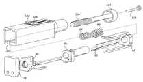
- FIG. 1is an exploded perspective view of the preferred embodiment of the present invention
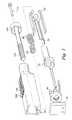
- FIG. 2is a perspective view of a stylet base
- FIG. 3is a perspective view of a cannula base
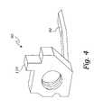
- FIG. 4is a perspective view of the stop pad
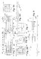
- FIG. 5is a side elevational cross section of the preferred embodiment of the invention.
- FIG. 5Ais a sectional view thereof taken along line A—A in FIG. 5;
- FIG. 5Bis a sectional view thereof taken along line B—B in FIG. 5;
- FIG. 5Cis a sectional view thereof taken along line C—C in FIG. 5;
- FIG. 5Dis a cut away view of the firing stylet latch lever
- FIG. 6is a top plan view of the invention.
- FIG. 7is a front elevational view thereof
- FIG. 8is a side elevational view thereof
- FIG. 9is a side elevational view of the retracting pin
- FIG. 10is a side elevational cross section of the invention, showing the stylet slide with a safety stylet latch lever engaged with a safety stylet housing notch and a firing stylet latch lever engaged with a firing stylet housing notch;
- FIG. 11is a side elevational cross sectional view thereof showing a resilient safety lever being used to disengage the safety stylet latch lever from the safety stylet housing notch;
- FIG. 12is a side elevational cross section thereof, showing the stop pad with a finger extending proximally, and also showing a locking cylinder and a cannula firing button;
- FIG. 13is a side elevational cross section thereof after the stylet base has advanced, showing the finger contacting a wedge portion of the stylet base and acting to disengage a safety cannula latch lever from a safety cannula notch;
- FIG. 14is a side elevational cross section thereof, showing a cannula firing button being depressed to move a locking cylinder off of a cylinder notch and into a bore, thereby allowing the cannula base to advance;
- FIG. 15is a side elevational cross section thereof, showing a retracting pin being used to push the cannula base to the first, retracted position, uncovering the tissue sample in the side-facing notch;
- FIG. 16is a side elevational cross section thereof, showing a knob being turned to rotate an adjusting screw, the adjusting screw retracting the stop pad to the first, retracted position;
- FIG. 17is a side elevational cross section thereof, showing the adjusting screw moving the stop pad to the distal end of the housing;
- FIG. 18is a side elevational cross section thereof, showing the stop pad being used to retract both the stylet and the cannula bases;
- FIG. 19is a side elevational cross section thereof, showing the knob being used to adjust the position of the stop pad, for adjusting the length of the stroke of the stylet and cannula.
- the biopsy needle device 10for taking tissue samples from a patient.
- the biopsy needle device 10includes an elongate housing 20 defining a cavity 22 .
- the housing 20is preferably constructed of lightweight plastic that is rigid but also fairly resilient.
- the cavity 22is shaped to contain the spring-loaded firing mechanism 48 described more fully below.
- Extending from the housing 20is an axially elongated stylet 30 having a distal end 32 and a proximal end 34 and defining a side-facing notch 36 adjacent the distal end 32 .
- a cannula 40coaxially disposed about the stylet 30 , the cannula 40 having a distal end 42 and a proximal end 44 .
- a typical stylet 30 and cannula 40is described in Haaga, U.S. Pat. No. 5,718,237, hereby incorporated by reference in full.
- the stylet 30is inserted into a section of tissue from which a sample is required, preferably by firing the stylet 30 into the tissue with the spring-loaded firing mechanism 48 .
- a portion of the tissueprolapses into the side-facing notch 36 adjacent the distal end 32 of the stylet 30 .
- the cannula 40is then spring fired over the side-facing notch 36 to sever the tissue sample and trap it in the side-facing notch 36 for subsequent removal from the patient.
- the housing 20 and the spring-loaded firing mechanism 48be as small and lightweight as possible so that the stylet 30 and cannula 40 can be positioned inside the patient's body in proximity to the tissue to be sampled without the weight of the device 10 causing excessive movement of the stylet 30 and cannula 40 inside the patient's body. Not only does movement of the stylet 30 and cannula 40 cause unnecessary damage to the patient's tissue, it also could cause the stylet 30 and cannula 40 , when fired, to miss the target tissue and cause the biopsy to give incorrect results.
- a stylet base 50is attached to the proximal end 34 of the stylet 30 and disposed in the cavity 22 . Both the stylet 30 and the stylet base 50 are mounted for axial movement relative to the housing 20 and relative to the cannula 40 between a first, retracted position and a second, extended position.
- the stylet base 50has a safety stylet latch means 52 for retaining the stylet 30 in the first, retracted position until released.
- the stylet base 50also has a firing stylet latch means 56 for retaining the stylet 30 in the first, retracted position after the safety stylet latch means 52 has been released.
- the stylet base 50also includes a wedge portion 60 described more fully below.
- the safety stylet latch means 52is preferably a safety stylet latch lever.
- the firing stylet latch means 56is preferably a firing stylet latch lever.
- the safety and firing stylet latch lever 52 and 56are biased towards a locking position. In their locking positions, the safety stylet latch lever 52 and the firing stylet latch lever interlock with a safety stylet housing notch 54 and a firing stylet housing notch 58 , respectively, to retain the stylet in the first, retracted position. As shown in FIG.
- the safety stylet latch lever 52preferably contacts the housing 20 at the safety stylet housing notch 54 ; and once the safety stylet latch lever 52 has been released, the stylet base 50 advances a small amount, thereby causing the firing stylet latch lever 56 to contact the firing stylet housing notch 58 . This small movement forward prevents the safety stylet latch lever 52 from re-engaging the housing 20 . Once the safety stylet latch lever 52 has been disengaged, only the firing stylet latch lever 56 restrains the stylet base 50 from moving forward.
- a cannula base 70is attached to the proximal end 44 of the cannula 40 and disposed in the cavity 22 .
- the stylet base 50is preferably coaxially disposed about and slidably engaging the cannula base 70 , and both the cannula 40 and the cannula base 70 are mounted for axial movement relative to the housing 20 , the stylet base 50 , and relative to the stylet 30 , between a first, retracted position and a second, extended position.
- the cannula base 70has a safety cannula latch means 72 for retaining the cannula base 70 in the first retracted position until released; and the cannula base 70 has a firing cannula latch means 76 for retaining the cannula base 70 in the first retracted position until released.
- the safety cannula latch means 72is preferably a safety cannula latch lever integral with the housing 20 .
- the safety cannula latch lever 72is preferably constructed with a resilient material, the lever 72 being biased towards a locked position in which the safety cannula latch lever 72 contacts a safety cannula notch 74 of the cannula base 70 to prevent the cannula base 70 from advancing from the first retracted position to the second extended position.
- the firing cannula latch means 76is preferably a locking cylinder that slidably engages a bore 78 in the side of the cannula base 70 .
- the locking cylinder 76slides between a retracted unlocking position and an extended locking position.
- a cylinder spring 80biases the locking cylinder 76 towards the extended locking position. While in the extended locking position, the locking cylinder 76 contacts a cylinder notch 82 of the housing 20 to keep the cannula base 70 in the first, retracted position.
- the device 10includes a means for biasing the stylet base distally 84 toward the second, extended position, and a means for biasing the cannula base distally 86 toward the second, extended position.
- the stylet biasing means 84is preferably disposed about and coaxially aligned with the cannula biasing means 86 .
- the cannula biasing means 86is preferably a cannula coil spring, preferably a smaller left-handed coil spring.
- the stylet biasing means 84is preferably a stylet coil spring, preferably a larger right-handed coil spring that is disposed about the cannula coil spring 86 , which is a smaller left-handed coil spring. The opposed windings of the coil springs prevent the two coil springs 84 and 86 from becoming tangled.
- the device 10includes a stop pad 90 .
- the stop pad 90operates to stop both the stylet base 50 and the cannula base 70 once they have moved, under the influence of the stylet and cannula coil springs 84 and 86 , from the first retracted position to the second extended position.
- the stop pad 90has a finger 92 extending from the stop pad 90 towards the stylet base 50 .
- the finger 92is biased towards a locked position, but movable to an unlocked position upon contact with the wedge portion 60 of the stylet base 50 .
- the finger 92contacts the wedge portion 60 of the stylet base 50 .
- the finger 92is bent to the unlocked position under the influence of the wedge portion 60 and operates to retract the safety cannula latch means 72 by pushing the safety cannula latch lever 72 into the unlocked position.
- the stop pad 90preferably includes a stop portion 94 that interacts with a stop finger 62 extending from the stylet base 50 to help stop the stylet base 50 , so that the resilient finger 92 does not have to bear the entire brunt of the impact when the stylet base 50 crashes into the stop pad 90 .
- the stop pad 90has a cannula base contacting portion 96 for stopping the cannula base 70 once it reaches its extended position.
- the device 10includes a means for adjusting the longitudinal position 100 of the stop pad 90 within the cavity 22 .
- the longitudinal adjusting means 100is preferably an externally threaded adjusting screw positioned longitudinally within the cavity 22 .
- a somewhat similar screwis described in Bennett, U.S. Pat. No. 5,335,672, hereby incorporated by reference in full.
- the stylet base 50 and the cannula base 70are coaxially disposed about the adjusting screw 100 , while the stop pad 90 is coaxially disposed about and threadedly engages the adjusting screw 100 .
- a proximal end 102 of the adjusting screw 100extends from a proximal end 24 of the housing 20 and terminates in a knob 104 .
- the stop pad 90preferably includes a stroke marker 110 that extends from the stop pad 90 and through a longitudinal slot 28 in the housing 20 .
- the usercan adjust the length of the stroke made by the stylet 30 and cannula by turning the knob 104 and adjusting the position of the stop pad 90 ; and the user can view the length of the stroke with visually confirming the location of the stroke marker 110 .
- indicia 29 etched into the face of the housing 20 adjacent to the longitudinal slot 28allow the precise adjustment of the stroke length of the stylet 30 and cannula 40 .
- the adjusting screw 100is preferably mounted against a resilient diaphragm 112 to dampen the impact of the stylet and cannula bases 50 and 70 against the stop pad 90 .
- the resilient diaphragm 112is amounted to cover an aperture in a distal end of the housing 20 , with a distal end of the adjusting screw 100 abutting the resilient diaphragm 112 .
- the shock of the stylet base 50 and the cannula base 70 hitting the stop pad 90is transmitted through the adjusting screw 100 and absorbed by the resilient diaphragm 112 .
- the device 10includes a means for retracting the stylet base 50 from the second extended position to the first, retracted position, for engagement of the safety stylet latch means 52 and the firing stylet latch means 56 , to retain the stylet 30 in the retracted position against the stylet coil spring 84 .
- the device 10also includes a means for retracting the cannula base 70 from the second, extended position to the first, retracted position for engagement of the safety cannula latch means 72 and the firing cannula latch means 76 , to retain the cannula base 70 in the retracted position against the cannula coil spring 86 .
- Various devicescan be devised by those skilled in the art for retracting the stylet and cannula bases 50 and 70 .
- the stylet and cannula retracting meansis a retracting pin 114 that fits through a stylet retracting hole 116 and a cannula retracting hole 118 , respectively, thereby allowing the user to manually push the stylet and cannula bases 50 and 70 to their first, retracted positions.
- the retracting pin 114is preferably stored in a pin storage chamber 106 located in the knob 104 .
- the usercan also retract the stylet and cannula bases 50 and 70 by turning the adjustment knob 104 until the stop pad 90 pushes the stylet and cannula bases 50 and 70 all the way to their first, retracted positions.
- the device 10includes a means for releasing 120 the safety stylet latch lever 52 , preferably a resilient safety lever integral 120 with the housing 20 .
- the resilient safety lever 120moves the safety stylet latch lever 52 off of the safety stylet housing notch 54 , allowing the stylet base 50 to advance distally.
- the firing stylet latch lever 52engages the firing stylet housing notch 58 , halting the further advance of the stylet base 50 .
- FIG. 1As shown in FIG.
- the device 10further includes a means for releasing 122 the firing stylet latch lever 56 , preferably a stylet firing button 122 mounted on a firing lever 124 integral with the housing 20 .
- a means for releasing 122 the firing stylet latch lever 56preferably a stylet firing button 122 mounted on a firing lever 124 integral with the housing 20 .
- the stylet firing button 122moves the firing lever 124 inwards, which moves the firing stylet latch lever 56 off of the firing stylet housing notch 58 , thereby allowing the stylet coil spring 84 to advance the stylet base 50 from the first, retracted position to the second, extended position.
- the wedge portion 60 of the stylet base 50contacts the finger 92 of the stop pad 90 , causing the finger 92 to move from the locked to the unlocked position and releasing the safety cannula latch lever 72 .
- the stop finger 62also preferably contacts the stop portion 94 of the stop pad 90 to assist in halting the moving stylet base 50 .
- the finger 92flexes and acts to disengage the safety cannula latch lever 72 from the safety cannula notch 74 .
- the cannula base 70can advance once the user activates a means for releasing the firing cannula latch means 126 , to allow the cannula base 70 to move from the first, retracted position to the second, extended position.
- the means for releasing the firing cannula latch means 126is preferably a cannula firing button. As shown in FIGS. 13 and 14, the cannula firing button 126 acts to depress the locking cylinder 76 into the bore 78 , disengaging the locking cylinder 76 from the cylinder notch 82 .
- the cannula firing button 126is preferably held in place, against the bias of the cylinder spring 80 , with a locking pin 130 .
- the cannula base 70will be released as soon as the stylet base 50 reaches the second extended position and releases the safety cannula latch lever 72 (automatic firing mode). If the user wishes, however, he can wait until later to press the cannula firing button 126 , and the cannula base 70 will not fire until this later time (semi-automatic firing mode).
- This configurationallows the user to fire both the stylet 30 and cannula 40 at precisely the desired time, without the danger of either the stylet 30 or the cannula 40 firing at the wrong time.
- the stylet 30 and cannula 40are removed from the patient's body.
- the cannula 40is then retracted by inserting the retracting pin 114 through the cannula retracting hole 118 and manually retracting the cannula base 70 to the first, retracted position.
- the cannula 40can be retracted with the adjusting screw 100 .
- the adjusting screw 100is used to fully retract the stylet and cannula bases 50 and 70 with the stop pad 90 .
- the stop pad 90is then moved distally while the safety stylet latch lever 52 and the firing stylet latch lever 56 are depressed, causing the stylet 30 to extend distally while the cannula 40 is held in the first, retracted position. Once the cannula 40 has been retracted, the tissue can be removed from the side-facing notch 36 for testing.
Landscapes
- Health & Medical Sciences (AREA)
- Life Sciences & Earth Sciences (AREA)
- Medical Informatics (AREA)
- Engineering & Computer Science (AREA)
- Biomedical Technology (AREA)
- Heart & Thoracic Surgery (AREA)
- Pathology (AREA)
- Molecular Biology (AREA)
- Surgery (AREA)
- Animal Behavior & Ethology (AREA)
- General Health & Medical Sciences (AREA)
- Public Health (AREA)
- Veterinary Medicine (AREA)
- Surgical Instruments (AREA)
Abstract
Description
1. Field of the Invention
This invention relates generally to biopsy needle devices, and more particularly to a disposable biopsy needle device that includes a safety latch and can be used in either an automatic or semi-automatic firing mode, the biopsy needle device having a dampening system that operates to minimize recoil when the device is fired.
2. Description of Related Art
Various biopsy needle devices are known in the art. A typical biopsy needle device known in the art uses a “stylet” in conjunction with a “cannula,” both described more fully, to cut a small tissue sample from a precise location within a patient. The stylet and cannula then function to remove the sample from the body for analysis. The typical biopsy needle device of the type comprising (a) an elongate housing, (b) aknob 104 at the first end of the housing, (c) first and second pistons extending from the second end of the housing, (d) connections on the extending ends of the pistons for connecting the stylet and cannula respectively, (e) first and second springs in the housing against which the first and second pistons, respectively, are cocked so that the springs apply a biasing force against the respective pistons, (f) a trigger successive movements wherein the first piston moves force of the first spring while the second piston remains in its cocked position, and after the first piston has moved to its fully extended position, the second piston moves to its fully extended position under the biasing force of the second spring.
A state of the art stylet and cannula is described in Haaga, U.S. Pat. No. 5,718,237. Haaga describes a biopsy needle having coaxial, telescopically inter-engaged stylet, inner and outer cannulas, which are axially and rotatably displaceable relative to one another. The stylet has a distal portion provided with a cutting recess for severing a biopsy specimen from a site in a patient, and the inner cannula has a distal portion for cutting and capturing the specimen in the recess for removal from the site upon withdrawal of the needle from the patient. The distal portion of the inner cannula is partially cut away to provide an insert recess which supports a semi-circular insert of hemostatic collagen which remains at the site upon removal of the needle to minimize hemorrhagic complications by promoting blood clotting. The insert and the distal portion of the inner cannula have radially outer surfaces of corresponding radius whereby the distal portion of the inner cannula and the insert supported therein are received within the distal end of the outer cannula prior to use of the needle.
Bennett, U.S. Pat. No. 5,335,672 describes an improvement in the cocking mechanism wherein the first and second pistons are moved to their cocked positions in separate distinct operations. The improved cocking mechanism comprises an annular ring near the second end of the housing. As the annular ring is rotated, it moves the second piston into its cocked position. The knob on the first end of the housing is pulled in a direction away from the first end of the housing to move the first piston into its cocked position.
Schramm et al. U.S. Pat. No. 5,507,298 describes an apparatus for the automated and facilitated handling and operation of a biopsy needle system, having a first needle component and a second needle component. The first and second needles are provided with first and second handles, respectively, which are fitted into first and second yokes of the apparatus. The apparatus is configured to maintain the first and second needles in a first position, during insertion of the biopsy needle- point into the tissue being sampled. The apparatus is further configured to forwardly move the first and second needles into subsequent positions, respectively, in rapid, automated succession so as to segment and enclose a tissue sample, which may be tested after removal of the biopsy needle system from the tissue. A tissue sample inspection feature permits facilitated repositioning and maintenance of the lo first needle relative to the second needle after retrieval of the tissue sample to enable inspection of the retrieved tissue sample without removal of either needle from the apparatus. The apparatus is further configured so as to be actuatable form position adjacent the front or the rear of the apparatus housing.
Nottke U.S. Pat. No. 4,924,878 describes a spring-powered actuating device for operating the obturator and the cannula of a biopsy needle, and a cocking device removably attachable to the actuating device. The actuating device has a manually operated trigger slide which controls separately the release of spring-powered slides for moving the obturator and the cannula so the surgeon determines the time interval between the release of the obturator and the later release of the cannula. The extent to which the trigger slide can be displaced manually is controlled by a manually adjustable safety slide which may be set in a first position to permit the trigger slide to release the slide for the obturator only and in a second position to permit the trigger slide to release the slide for the cannula. The cocking device, when attached to the actuating device by squeezing them together manually and when so moved it retracts the slides for the obturator and the cannula to stress their springs which power them.
Akerfeldt U.S. Pat. No. 4,953,558 describes an invention referring to a driving unit for advice for tissue sampling. The device comprises in addition to the driving unit a needle unit comprising a hollow outer needle and slidably disposed therein an inner needle, the driving unit being used to propel the needles. The driving unit comprises a driving device for each mechanism adapted to be pretensioned. The driving unit in addition comprises an inner guide sleeve containing two successive needle holders adapted to be shifted in relation to each other in longitudinal direction of the sleeve and adapted to be pre-tensioned in the same direction for propelling the needles with the aid of one spring each and which are provided with releasable locking means. A manual triggering device is provided for releasing the one needle holder who in turn is adapted during the final phase of its propulsion to release the other needle holder. A tensioning sleeve which rotatable surrounds the guide sleeve is provided with cam surfaces cooperating with the needle holders to pre-tension them against he spring force.
Ohto et al., U.S. Pat. No. 5,505,211 describes the set of biopsy needles of the invention is provided with a shaft member for an inner needle which has an inner needle base at the front end to fix an inner needle, a shaft member for an outer needle which has an outer needle base at the front end to fix an outer needle, a gripping member for operation which fixes the shaft member for the inner needle and axially movable support the shaft for the outer needle, a actuating member which gives protrusion force to the shaft member for the outer needle, a holding member which holds the shaft member for the outer needle at the position before protrusion against the protrusion force of the actuating member and releases from holding the shaft member for the outer needle before protrusion by outside operation, and a rotation generating member which gives rotation force to the shaft member for the outer needle when the shaft member for the outer needle moves axially.
Taylor, U.S. Pat. No. 4,907,599 describes the soft tissue core biopsy instrument comprising a proximal outer barrel member and a distal inner barrel member, which is slidably received within the outer barrel member. A cannula driver is slidably received within the distal inner barrel member and has a distally extending cannula fixed thereto. A stylet extends distally from a stylet hub with a stylet hub being removably attached to the proximal outer barrel member. A spring is positioned within the inner barrel member between a proximal wall thereof and a proximal wall of the cannula driver for biasing the cannula driver forwardly and a latching mechanism for latching the cannula driver in a proximally retracted position against the action of spring is also provided. A trigger for unlatching the latching mechanism may be actuated to allow the spring to quickly return to its forwardly biased position, shooting or forcing the cannula driver to a distally extended position, projecting the cannula over the stylet.
Taylor, U.S. Pat. No. 4,881,551 describes the soft tissue core biopsy instrument comprises a proximal outer barrel member having a distal end and a proximal end; a distal inner barrel member which is slidably received within the outer barrel member, which has a distal end and a proximal end and which has a stop in the inner barrel member; a cannula extending distally from the inner barrel member, being fixed to the cannula driver, and having a distal tip, the cannula driver being slidably received in and movable within the inner barrel member and the inner barrel member and the cannula extending a predetermined distance out of a distal end of the inner barrel member when the instrument is in an at-rest condition; a stylet having a distal end, a proximal end, and being removable received in the outer barrel, in the inner barrel, and in the cannula, the distal end having a biopsy sample receiving notch therein; a stylet hub mounted to the proximal end of the stylet; the stylet hub being removably attached to the proximal end of the proximal outer barrel member to enable multiple biopsies to be obtained with one insertion of the cannula, the stylet extending distally from the hub and within the cannula and having a distal tip portion positioned within the cannula when the instrument is in an at-rest position and extending distally of the distal tip of the cannula in position to capture a biopsy sample when the instrument is in a cocked condition; biasing means within the inner barrel member between the stop and the cannula driver for biasing the cannula driver as the inner barrel member for latching the cannula driver in a proximally retracted cocked position within the outer barrel member and the biasing means; and a trigger, associated with the latching means, for unlatching the latching means, the trigger, upon being actuated for unlatching of the latching means, allowing the biasing means to quickly return the cannula driver and the cannula to the distally extending position thereof and over the stylet distal tip portion.
Leigh et al., U.S. Pat. No. 5,172,702 describes a soft tissue biopsy apparatus for obtaining a tissue specimen. An elongate housing has an opening at one end. A hollow cannula is positioned within the housing, is reciprocally movable there within, and one end of the needle extends through the opening for insertion into tissue from which a specimen is to be taken. A needle is positioned within the cannula, reciprocally movable there within, and also has an end extending through the opening for insertion into the tissue. This needle has a recess adjacent its outer end in which a tissue specimen is captured. The needle is connected to a slide by which the needle is moved independently of the cannula. A sleeve installed over the housing is manually operable to move the slide to a selected and cocked position prior to insertion of the cannula/needle into the tissue. Movements of the slide moves the second needle form a first position to a second position while the cannula remains stationary. A release mechanism operable by the user after the insertion of the assembly into the tissue initially returns the needle to its first position and then moves the cannula from a first position to a second position. Movement of the cannula to its second position causes the end of the cannula to cover the end of the needle to capture the tissues specimen within the recess.
The prior art teaches biopsy devices that have the following features: (i) an adjustment mechanism that allows the stroke length of the device to be adjusted, (ii) safety latches to prevent accidental firing, (iii) two overlapping and coaxially aligned coil springs, (iv) a firing mechanism that can be fired in automatic mode or in semi-automatic mode. However, the prior art does not teach a biopsy device that offers all of these features in a single compact housing. The prior art also does not teach a shock dampening device to minimize the recoil of the device when fired. The present invention fulfills these needs and provides further related advantages as described in the following summary.
The present invention teaches certain benefits in construction and use which give rise to the objectives described below.
The present invention provides a biopsy needle device having an axially elongated stylet and a cannula coaxially disposed thereabout, the stylet and cannula being mounted on stylet and cannula bases that are slidably mounted within a cavity of an elongate housing. The cavity also contains a spring-loaded firing mechanism for firing the stylet and cannula for taking a tissue sample from a patient. The stylet base contains a safety stylet latch means and a firing stylet latch means for retaining the stylet in the first, retracted position until released. The cannula base includes a safety cannula latch means and a firing cannula latch means for retaining the cannula base in the first retracted position until released. Once the safety and firing stylet latch means have been released, the stylet base advances to contact a finger of the stop pad, thereby releasing the safety cannula latch lever. The tissue of the patient prolapses into a side-facing notch of the advancing stylet. Once the firing cannula latch lever has been released, the cannula base advances to contact the stop pad, thereby causing the cannula to advance to cover the side-facing notch, thereby severing and containing the tissue. In the preferred embodiment, the stop pad transmits the force of the impact of both the stylet and cannula bases, through a longitudinal adjustment means, to a resilient diaphragm of the housing, thereby dampening the force of the impacts.
A primary objective of the present invention is to provide a biopsy needle device having advantages not taught by the prior art.
Another objective is to provide a single compact biopsy needle device that includes all of the following features: (i) an adjustment mechanism that allows the stroke length of the device to be adjusted, (ii) safety latches to prevent accidental firing, (iii) two overlapping and coaxially aligned coil springs, (iv) a firing mechanism that can be fired in automatic mode or in semi-automatic mode.
A further objective is to provide a biopsy needle device that includes a shock dampening device to minimize the recoil of the device when fired.
Other features and advantages of the present invention will become apparent from the following more detailed description, taken in conjunction with the accompanying drawings, which illustrate, by way of example, the principles of the invention.
The accompanying drawings illustrate the present invention. In such drawings:
FIG. 1 is an exploded perspective view of the preferred embodiment of the present invention;
FIG. 2 is a perspective view of a stylet base;
FIG. 3 is a perspective view of a cannula base;
FIG. 4 is a perspective view of the stop pad;
FIG. 5 is a side elevational cross section of the preferred embodiment of the invention;
FIG. 5A is a sectional view thereof taken along line A—A in FIG. 5;
FIG. 5B is a sectional view thereof taken along line B—B in FIG. 5;
FIG. 5C is a sectional view thereof taken along line C—C in FIG. 5;
FIG. 5D is a cut away view of the firing stylet latch lever;
FIG. 6 is a top plan view of the invention;
FIG. 7 is a front elevational view thereof;
FIG. 8 is a side elevational view thereof;
FIG. 9 is a side elevational view of the retracting pin;
FIG. 10 is a side elevational cross section of the invention, showing the stylet slide with a safety stylet latch lever engaged with a safety stylet housing notch and a firing stylet latch lever engaged with a firing stylet housing notch;
FIG. 11 is a side elevational cross sectional view thereof showing a resilient safety lever being used to disengage the safety stylet latch lever from the safety stylet housing notch;
FIG. 12 is a side elevational cross section thereof, showing the stop pad with a finger extending proximally, and also showing a locking cylinder and a cannula firing button;
FIG. 13 is a side elevational cross section thereof after the stylet base has advanced, showing the finger contacting a wedge portion of the stylet base and acting to disengage a safety cannula latch lever from a safety cannula notch;
FIG. 14 is a side elevational cross section thereof, showing a cannula firing button being depressed to move a locking cylinder off of a cylinder notch and into a bore, thereby allowing the cannula base to advance;
FIG. 15 is a side elevational cross section thereof, showing a retracting pin being used to push the cannula base to the first, retracted position, uncovering the tissue sample in the side-facing notch;
FIG. 16 is a side elevational cross section thereof, showing a knob being turned to rotate an adjusting screw, the adjusting screw retracting the stop pad to the first, retracted position;
FIG. 17 is a side elevational cross section thereof, showing the adjusting screw moving the stop pad to the distal end of the housing;
FIG. 18 is a side elevational cross section thereof, showing the stop pad being used to retract both the stylet and the cannula bases; and
FIG. 19 is a side elevational cross section thereof, showing the knob being used to adjust the position of the stop pad, for adjusting the length of the stroke of the stylet and cannula.
The above described drawing figures illustrate the invention, a biopsy needle device10 for taking tissue samples from a patient. As shown in FIG. 5, the biopsy needle device10 includes anelongate housing 20 defining acavity 22. Thehousing 20 is preferably constructed of lightweight plastic that is rigid but also fairly resilient. Thecavity 22 is shaped to contain the spring-loaded firing mechanism48 described more fully below. Extending from thehousing 20 is an axiallyelongated stylet 30 having adistal end 32 and aproximal end 34 and defining a side-facingnotch 36 adjacent thedistal end 32. Acannula 40 coaxially disposed about thestylet 30, thecannula 40 having adistal end 42 and aproximal end 44. Atypical stylet 30 andcannula 40, well known in the art, is described in Haaga, U.S. Pat. No. 5,718,237, hereby incorporated by reference in full. In use thestylet 30 is inserted into a section of tissue from which a sample is required, preferably by firing thestylet 30 into the tissue with the spring-loaded firing mechanism48. A portion of the tissue prolapses into the side-facingnotch 36 adjacent thedistal end 32 of thestylet 30. Thecannula 40 is then spring fired over the side-facingnotch 36 to sever the tissue sample and trap it in the side-facingnotch 36 for subsequent removal from the patient. It is preferred that thehousing 20 and the spring-loaded firing mechanism48 be as small and lightweight as possible so that thestylet 30 andcannula 40 can be positioned inside the patient's body in proximity to the tissue to be sampled without the weight of the device10 causing excessive movement of thestylet 30 andcannula 40 inside the patient's body. Not only does movement of thestylet 30 andcannula 40 cause unnecessary damage to the patient's tissue, it also could cause thestylet 30 andcannula 40, when fired, to miss the target tissue and cause the biopsy to give incorrect results.
As shown in FIGS. 1 and 2, astylet base 50 is attached to theproximal end 34 of thestylet 30 and disposed in thecavity 22. Both thestylet 30 and thestylet base 50 are mounted for axial movement relative to thehousing 20 and relative to thecannula 40 between a first, retracted position and a second, extended position. Thestylet base 50 has a safety stylet latch means52 for retaining thestylet 30 in the first, retracted position until released. Thestylet base 50 also has a firing stylet latch means56 for retaining thestylet 30 in the first, retracted position after the safety stylet latch means52 has been released. Thestylet base 50 also includes awedge portion 60 described more fully below. The safety stylet latch means52 is preferably a safety stylet latch lever. The firing stylet latch means56 is preferably a firing stylet latch lever. The safety and firingstylet latch lever stylet latch lever 52 and the firing stylet latch lever interlock with a safetystylet housing notch 54 and a firingstylet housing notch 58, respectively, to retain the stylet in the first, retracted position. As shown in FIG. 10, the safetystylet latch lever 52 preferably contacts thehousing 20 at the safetystylet housing notch 54; and once the safetystylet latch lever 52 has been released, thestylet base 50 advances a small amount, thereby causing the firingstylet latch lever 56 to contact the firingstylet housing notch 58. This small movement forward prevents the safetystylet latch lever 52 from re-engaging thehousing 20. Once the safetystylet latch lever 52 has been disengaged, only the firingstylet latch lever 56 restrains thestylet base 50 from moving forward.
As shown in FIGS. 1 and 3, acannula base 70 is attached to theproximal end 44 of thecannula 40 and disposed in thecavity 22. Thestylet base 50 is preferably coaxially disposed about and slidably engaging thecannula base 70, and both thecannula 40 and thecannula base 70 are mounted for axial movement relative to thehousing 20, thestylet base 50, and relative to thestylet 30, between a first, retracted position and a second, extended position. Thecannula base 70 has a safety cannula latch means72 for retaining thecannula base 70 in the first retracted position until released; and thecannula base 70 has a firing cannula latch means76 for retaining thecannula base 70 in the first retracted position until released. The safety cannula latch means72 is preferably a safety cannula latch lever integral with thehousing 20. The safetycannula latch lever 72 is preferably constructed with a resilient material, thelever 72 being biased towards a locked position in which the safetycannula latch lever 72 contacts asafety cannula notch 74 of thecannula base 70 to prevent thecannula base 70 from advancing from the first retracted position to the second extended position. Only after thestylet base 50 has moved to the second extended position, in a process described below, is the safetycannula latch lever 72 disengaged from thesafety cannula notch 74. The firing cannula latch means76 is preferably a locking cylinder that slidably engages abore 78 in the side of thecannula base 70. The lockingcylinder 76 slides between a retracted unlocking position and an extended locking position. Acylinder spring 80 biases the lockingcylinder 76 towards the extended locking position. While in the extended locking position, the lockingcylinder 76 contacts a cylinder notch82 of thehousing 20 to keep thecannula base 70 in the first, retracted position.
As shown in FIG. 5, the device10 includes a means for biasing the stylet base distally84 toward the second, extended position, and a means for biasing the cannula base distally86 toward the second, extended position. The stylet biasing means84 is preferably disposed about and coaxially aligned with the cannula biasing means86. The cannula biasing means86 is preferably a cannula coil spring, preferably a smaller left-handed coil spring. The stylet biasing means84 is preferably a stylet coil spring, preferably a larger right-handed coil spring that is disposed about thecannula coil spring 86, which is a smaller left-handed coil spring. The opposed windings of the coil springs prevent the twocoil springs
As shown in FIGS. 1 and 4, the device10 includes astop pad 90. Thestop pad 90 operates to stop both thestylet base 50 and thecannula base 70 once they have moved, under the influence of the stylet and cannula coil springs84 and86, from the first retracted position to the second extended position. As shown in FIG. 4, thestop pad 90 has afinger 92 extending from thestop pad 90 towards thestylet base 50. Thefinger 92 is biased towards a locked position, but movable to an unlocked position upon contact with thewedge portion 60 of thestylet base 50. In use, when thestylet base 50 slides into thestop pad 90, thefinger 92 contacts thewedge portion 60 of thestylet base 50. As shown in FIG. 13, thefinger 92 is bent to the unlocked position under the influence of thewedge portion 60 and operates to retract the safety cannula latch means72 by pushing the safetycannula latch lever 72 into the unlocked position. Thestop pad 90 preferably includes a stop portion94 that interacts with astop finger 62 extending from thestylet base 50 to help stop thestylet base 50, so that theresilient finger 92 does not have to bear the entire brunt of the impact when thestylet base 50 crashes into thestop pad 90. Finally, thestop pad 90 has a cannulabase contacting portion 96 for stopping thecannula base 70 once it reaches its extended position.
As shown in FIGS. 1 and 5, the device10 includes a means for adjusting thelongitudinal position 100 of thestop pad 90 within thecavity 22. The longitudinal adjusting means100 is preferably an externally threaded adjusting screw positioned longitudinally within thecavity 22. A somewhat similar screw is described in Bennett, U.S. Pat. No. 5,335,672, hereby incorporated by reference in full. Thestylet base 50 and thecannula base 70 are coaxially disposed about the adjustingscrew 100, while thestop pad 90 is coaxially disposed about and threadedly engages the adjustingscrew 100. Aproximal end 102 of the adjustingscrew 100 extends from a proximal end24 of thehousing 20 and terminates in aknob 104. In use, the user turns theknob 104, rotating the adjustingscrew 100, and adjusting the position of thestop pad 90 within thecavity 22. Thestop pad 90 preferably includes astroke marker 110 that extends from thestop pad 90 and through alongitudinal slot 28 in thehousing 20. In use, the user can adjust the length of the stroke made by thestylet 30 and cannula by turning theknob 104 and adjusting the position of thestop pad 90; and the user can view the length of the stroke with visually confirming the location of thestroke marker 110. As shown in FIG. 6,indicia 29 etched into the face of thehousing 20 adjacent to thelongitudinal slot 28 allow the precise adjustment of the stroke length of thestylet 30 andcannula 40. The adjustingscrew 100 is preferably mounted against a resilient diaphragm112 to dampen the impact of the stylet andcannula bases stop pad 90. The resilient diaphragm112 is amounted to cover an aperture in a distal end of thehousing 20, with a distal end of the adjustingscrew 100 abutting the resilient diaphragm112. The shock of thestylet base 50 and thecannula base 70 hitting thestop pad 90 is transmitted through the adjustingscrew 100 and absorbed by the resilient diaphragm112.
The device10 includes a means for retracting thestylet base 50 from the second extended position to the first, retracted position, for engagement of the safety stylet latch means52 and the firing stylet latch means56, to retain thestylet 30 in the retracted position against thestylet coil spring 84. The device10 also includes a means for retracting thecannula base 70 from the second, extended position to the first, retracted position for engagement of the safety cannula latch means72 and the firing cannula latch means76, to retain thecannula base 70 in the retracted position against thecannula coil spring 86. Various devices can be devised by those skilled in the art for retracting the stylet andcannula bases pin 114 that fits through a stylet retracting hole116 and acannula retracting hole 118, respectively, thereby allowing the user to manually push the stylet andcannula bases pin 114 is preferably stored in a pin storage chamber106 located in theknob 104. In the preferred embodiment, as shown in FIGS. 16 and 17, the user can also retract the stylet andcannula bases adjustment knob 104 until thestop pad 90 pushes the stylet andcannula bases
As shown in FIGS. 8 and 10, the device10 includes a means for releasing120 the safetystylet latch lever 52, preferably a resilient safety lever integral120 with thehousing 20. When pressed inwards, theresilient safety lever 120 moves the safetystylet latch lever 52 off of the safetystylet housing notch 54, allowing thestylet base 50 to advance distally. Once thestylet base 50 advances a small amount, as described above and as shown in FIG. 11, the firingstylet latch lever 52 engages the firingstylet housing notch 58, halting the further advance of thestylet base 50. As shown in FIG. 6, the device10 further includes a means for releasing122 the firingstylet latch lever 56, preferably astylet firing button 122 mounted on a firing lever124 integral with thehousing 20. When pressed inwards, thestylet firing button 122 moves the firing lever124 inwards, which moves the firingstylet latch lever 56 off of the firingstylet housing notch 58, thereby allowing thestylet coil spring 84 to advance thestylet base 50 from the first, retracted position to the second, extended position. Once thestylet base 50 has advanced, as shown in FIG. 13, thewedge portion 60 of thestylet base 50 contacts thefinger 92 of thestop pad 90, causing thefinger 92 to move from the locked to the unlocked position and releasing the safetycannula latch lever 72. Thestop finger 62 also preferably contacts the stop portion94 of thestop pad 90 to assist in halting the movingstylet base 50. As described above, thefinger 92 flexes and acts to disengage the safetycannula latch lever 72 from thesafety cannula notch 74.
Once all of the above have occurred, thecannula base 70 can advance once the user activates a means for releasing the firing cannula latch means126, to allow thecannula base 70 to move from the first, retracted position to the second, extended position. The means for releasing the firing cannula latch means126 is preferably a cannula firing button. As shown in FIGS. 13 and 14, thecannula firing button 126 acts to depress thelocking cylinder 76 into thebore 78, disengaging the lockingcylinder 76 from the cylinder notch82. Thecannula firing button 126 is preferably held in place, against the bias of thecylinder spring 80, with alocking pin 130. In use, if the user presses thecannula firing button 126 at the same time he presses thestylet firing button 122, thecannula base 70 will be released as soon as thestylet base 50 reaches the second extended position and releases the safety cannula latch lever72 (automatic firing mode). If the user wishes, however, he can wait until later to press thecannula firing button 126, and thecannula base 70 will not fire until this later time (semi-automatic firing mode). This configuration allows the user to fire both thestylet 30 andcannula 40 at precisely the desired time, without the danger of either thestylet 30 or thecannula 40 firing at the wrong time.
Once the device10 has been fired, thestylet 30 andcannula 40 are removed from the patient's body. Thecannula 40 is then retracted by inserting the retractingpin 114 through thecannula retracting hole 118 and manually retracting thecannula base 70 to the first, retracted position. Alternatively, as shown in FIGS. 16 and 17, thecannula 40 can be retracted with the adjustingscrew 100. The adjustingscrew 100 is used to fully retract the stylet andcannula bases stop pad 90. Thestop pad 90 is then moved distally while the safetystylet latch lever 52 and the firingstylet latch lever 56 are depressed, causing thestylet 30 to extend distally while thecannula 40 is held in the first, retracted position. Once thecannula 40 has been retracted, the tissue can be removed from the side-facingnotch 36 for testing.
While the invention has been described with reference to at least one preferred embodiment, it is to be clearly understood by those skilled in the art that the invention is not limited thereto. Rather, the scope of the invention is to be interpreted only in conjunction with the appended claims.
Claims (8)
1. A biopsy needle device comprising:
a housing defining a cavity;
extending from the housing, an axially elongated stylet having a distal end and a proximal end and defining a side-facing notch adjacent the distal end;
a cannula coaxially disposed about the stylet, the cannula having a distal end and a proximal end;
a stylet base attached to the proximal end of the stylet and disposed in the cavity, the stylet and the stylet base being mounted for axial movement relative to the housing and relative to the cannula between a first, retracted position and a second, extended position, the stylet base having
a safety stylet latch means for retaining the stylet in the first, retracted position until released,
a firing stylet latch means for retaining the stylet in the first, retracted position after the safety stylet latch means has been released, and
a wedge portion;
a cannula base attached to the proximal end of the cannula and disposed in the cavity, the cannula and the cannula base being mounted for axial movement relative to the housing and relative to the stylet between a first, retracted position and a second, extended position, the cannula base having
a safety cannula latch means for retaining the cannula base in the first retracted position until released, and
a firing cannula latch means for retaining the cannula base in the first retracted position until released;
a means for biasing the stylet base distally toward the second, extended position;
a means for biasing the cannula base distally toward the second, extended position;
a stop pad having
a finger biased towards a locked position but movable to an unlocked position upon contact with the wedge portion of the stylet base, the finger operating to retract the safety cannula latch means when positioned in the unlocked position,
a cannula base contacting portion for contacting the cannula base once it reaches its extended position, and
a means for adjusting the longitudinal position of the stop pad within the cavity;
a means for retracting the stylet base from the second extended position to the first, retracted position for engagement of the safety stylet latch means and the firing stylet latch means, to retain the stylet in the retracted position against the means for biasing the stylet distally;
a means for retracting the cannula base from the second, extended position to the first, retracted position for engagement of the safety cannula latch means and the firing cannula latch means, to retain the cannula base in the retracted position against the means for biasing the cannula distally;
a means for releasing the safety stylet latch means;
a means for releasing the firing stylet latch means to allow the stylet base to move from the first, retracted position to the second, extended position, thereby causing the finger of the stop pad to contact the wedge portion, the finger moving from the locked to the unlocked position and releasing the safety cannula latch means; and
a means for releasing the firing cannula latch means to allow the cannula base to move from the first, retracted position to the second, extended position.
2. The device ofclaim 1 wherein the stylet base is coaxially disposed about and slidably engaging the cannula base.
3. The device ofclaim 1 wherein the stylet biasing means is disposed about and coaxially aligned with the cannula biasing means.
4. The device ofclaim 3 wherein the cannula biasing means is a smaller left-handed coil spring, and the stylet biasing means is a larger right-handed coil spring disposed about the smaller left-handed coil spring.
5. The device ofclaim 1 wherein the longitudinal adjusting means is an externally threaded adjusting screw positioned longitudinally within the cavity, the stylet base and the cannula base being coaxially disposed about and the stop pad threadedly engaging the adjusting screw.
6. The device ofclaim 5 wherein an aperture in a distal end of the housing is covered by a resilient diaphragm; a proximal end of the adjusting screw extends from a proximal end of the housing and terminates in a knob; and a distal end of the adjusting screw abuts the resilient diaphragm, whereby turning the knob adjusts the longitudinal position of the stop pad, and the shock of the stylet base and the cannula base hitting the stop pad is transmitted through the adjusting screw and absorbed by the resilient diaphragm.
7. A method of taking a tissue sample, the method comprising the steps of:
a) providing a biopsy needle device comprising:
a housing defining a cavity, the housing having a safety stylet housing notch, a firing stylet housing notch, a safety cannula notch, and a cylinder notch;
extending from the housing, an axially elongated stylet having a distal end and a proximal end and defining a side-facing notch adjacent the distal end;
a cannula coaxially disposed about the stylet, the cannula having a distal end and a proximal end;
a stylet base attached to the proximal end of the stylet and disposed in the cavity, the stylet and the stylet base being mounted for axial movement relative to the housing and relative to the cannula between a first, retracted position and a second, extended position, the stylet base having
a safety stylet latch means for retaining the stylet in the first, retracted position until released,
a firing stylet latch means for retaining the stylet in the first, retracted position after the safety stylet latch means has been released, and
a wedge portion;
a cannula base attached to the proximal end of the cannula and disposed in the cavity, the cannula and the cannula base being mounted for axial movement relative to the housing and relative to the stylet between a first, retracted position and a second, extended position, the cannula base having
a safety cannula latch means for retaining the cannula base in the first retracted position until released, and, adjacent thereto, a means for releasing the safety cannula latch means, and
a firing cannula latch means for retaining the cannula base in the first retracted position until released, and, adjacent thereto, a means for releasing the firing cannula latch means;
a means for biasing the stylet base distally toward the second, extended position;
a means for biasing the cannula base distally toward the second, extended position; and
a stop pad having
a finger biased towards a locked position but movable to an unlocked position upon contact with the wedge portion of the stylet base, the finger operating to retract the safety cannula latch means when positioned in the unlocked position,
a cannula base contacting portion for contacting the cannula base once it reaches its extended position, and
a means for adjusting the longitudinal position of the stop pad within the cavity;
b) moving the stop pad proximally, with the means for adjusting the longitudinal position of the stop pad, until the safety stylet latch means engages the safety stylet housing notch, the firing stylet latch means engages the firing stylet housing notch, the safety cannula latch means engages the safety cannula notch, and the firing cannula latch means engages the cylinder notch;
c) moving the stop pad distally, with the means for adjusting the longitudinal position of the stop pad, until the desired stroke length is achieved;
d) pressing the means for releasing the safety stylet latch means;
e) inserting the stylet into a patient such that the side-facing notch is adjacent to the tissue from which a biopsy is desired;
f) pressing the means for releasing the firing stylet latch means to allow the stylet base to move distally from the first, retracted position, causing the stylet to move distally and penetrate the patient's tissue, which prolapses into the side-facing notch, also causing the finger of the stop pad to contact the wedge portion once the stylet base reaches the second, extended position, contact with the wedge portion biasing the finger from the locked to the unlocked position, thereby triggering the means for releasing the safety cannula latch means, which disengages the safety cannula latch means from the safety cannula notch;
g) pressing the means for releasing the firing cannula latch means to allow the cannula to move from the first, retracted position to the second, extended position, thereby severing and capturing the tissue in the side-facing notch;
h) removing the stylet and cannula from the patient's body; and
i) retracting the cannula, thereby releasing the severed tissue for testing.
8. The method ofclaim 7 further comprising the step of:
a′) providing a resilient diaphragm mounted at the distal end of the housing; and
a″) mounting a distal end of the longitudinal adjusting means against the resilient diaphragm.
Priority Applications (3)
| Application Number | Priority Date | Filing Date | Title |
|---|---|---|---|
| US09/494,895US6358217B1 (en) | 2000-01-31 | 2000-01-31 | Automatic and semi-automatic disposable biopsy needle device |
| AU2001233216AAU2001233216A1 (en) | 2000-01-31 | 2001-01-31 | Biopsy needle device |
| PCT/US2001/003291WO2001054574A1 (en) | 2000-01-31 | 2001-01-31 | Biopsy needle device |
Applications Claiming Priority (1)
| Application Number | Priority Date | Filing Date | Title |
|---|---|---|---|
| US09/494,895US6358217B1 (en) | 2000-01-31 | 2000-01-31 | Automatic and semi-automatic disposable biopsy needle device |
Publications (1)
| Publication Number | Publication Date |
|---|---|
| US6358217B1true US6358217B1 (en) | 2002-03-19 |
Family
ID=23966404
Family Applications (1)
| Application Number | Title | Priority Date | Filing Date |
|---|---|---|---|
| US09/494,895Expired - LifetimeUS6358217B1 (en) | 2000-01-31 | 2000-01-31 | Automatic and semi-automatic disposable biopsy needle device |
Country Status (3)
| Country | Link |
|---|---|
| US (1) | US6358217B1 (en) |
| AU (1) | AU2001233216A1 (en) |
| WO (1) | WO2001054574A1 (en) |
Cited By (109)
| Publication number | Priority date | Publication date | Assignee | Title |
|---|---|---|---|---|
| US20040153002A1 (en)* | 2003-01-31 | 2004-08-05 | Schramm John B. | Integrated biopsy needle assembly |
| US20040186393A1 (en)* | 2003-03-19 | 2004-09-23 | Leigh Harold G. | Soft tissue biopsy instrument |
| EP1417932A3 (en)* | 2002-11-07 | 2004-12-22 | Aurelio Gironi | Device for needle-biopsy |
| US20050165328A1 (en)* | 2002-03-19 | 2005-07-28 | Norbert Heske | Biopsy device and biopsy needle module that can be inserted into the biopsy device |
| US20050277845A1 (en)* | 2004-05-27 | 2005-12-15 | David Cooke | Medical instrument |
| WO2006005342A1 (en)* | 2004-07-09 | 2006-01-19 | Sonion Roskilde A/S | Firing system for biopsy device |
| US20060036271A1 (en)* | 2004-07-29 | 2006-02-16 | X-Sten, Inc. | Spinal ligament modification devices |
| US20060089565A1 (en)* | 2004-10-21 | 2006-04-27 | Inter-V Manan | Forward-fired automatic tissue sampling apparatus with safety lock |
| US20060116604A1 (en)* | 2002-11-20 | 2006-06-01 | Adams Leland R | Medical instrument |
| US20060116573A1 (en)* | 2003-11-17 | 2006-06-01 | Inrad, Inc. | Self Contained, Self Piercing, Side-Expelling Marking Apparatus |
| US20070106176A1 (en)* | 2003-10-14 | 2007-05-10 | Mark Joseph L | Vacuum assisted biopsy needle set |
| US20070123890A1 (en)* | 2005-11-04 | 2007-05-31 | X-Sten, Corp. | Tissue retrieval devices and methods |
| US20070167869A1 (en)* | 2005-03-02 | 2007-07-19 | Roe Steven N | System and method for breaking a sterility seal to engage a lancet |
| US20070299459A1 (en)* | 2006-06-26 | 2007-12-27 | X-Sten Corp. | Percutaneous Tissue Access Device |
| US20080200833A1 (en)* | 2003-10-14 | 2008-08-21 | Hardin Terry D | Vacuum assisted biopsy device |
| US20080221481A1 (en)* | 2003-10-14 | 2008-09-11 | Mark Joseph L | Vacuum assisted biopsy needle set |
| US20080221383A1 (en)* | 2007-02-12 | 2008-09-11 | Vertos Medical, Inc. | Tissue excision devices and methods |
| US20080281226A1 (en)* | 2004-05-11 | 2008-11-13 | Inrad, Inc. | Core Biopsy Device with Specimen Length Adjustment |
| US20080287825A1 (en)* | 2007-05-14 | 2008-11-20 | Boston Scientific Scimed, Inc. | Biopsy Device |
| US20090036936A1 (en)* | 2006-05-09 | 2009-02-05 | Vertos Medical, Inc. | Translaminar approach to minimally invasive ligament decompression procedure |
| US20090082696A1 (en)* | 2003-10-14 | 2009-03-26 | Nicoson Zachary R | Vacuum assisted biopsy device |
| US20090118709A1 (en)* | 2007-11-06 | 2009-05-07 | Vertos Medical, Inc. A Delaware Corporation | Tissue Excision Tool, Kits and Methods of Using the Same |
| USD598549S1 (en) | 2008-09-16 | 2009-08-18 | Vertos Medical, Inc. | Surgical trocar |
| US20090270761A1 (en)* | 2002-11-20 | 2009-10-29 | Boston Scientific Scimed, Inc. | Medical Instrument |
| US20090299220A1 (en)* | 2008-05-30 | 2009-12-03 | Inrad, Inc. | Biopsy Device Having Specimen Length Adjustment |
| USD606654S1 (en) | 2006-07-31 | 2009-12-22 | Vertos Medical, Inc. | Tissue excision device |
| USD610259S1 (en) | 2008-10-23 | 2010-02-16 | Vertos Medical, Inc. | Tissue modification device |
| USD611146S1 (en) | 2008-10-23 | 2010-03-02 | Vertos Medical, Inc. | Tissue modification device |
| USD619252S1 (en) | 2008-10-23 | 2010-07-06 | Vertos Medical, Inc. | Tissue modification device |
| USD619253S1 (en) | 2008-10-23 | 2010-07-06 | Vertos Medical, Inc. | Tissue modification device |
| USD620593S1 (en) | 2006-07-31 | 2010-07-27 | Vertos Medical, Inc. | Tissue excision device |
| USD621939S1 (en) | 2008-10-23 | 2010-08-17 | Vertos Medical, Inc. | Tissue modification device |
| US20110054349A1 (en)* | 2007-12-27 | 2011-03-03 | Devicor Medical Products, Inc. | Clutch and valving system for tetherless biopsy device |
| USD635671S1 (en) | 2008-10-23 | 2011-04-05 | Vertos Medical, Inc. | Tissue modification device |
| USD640977S1 (en) | 2009-09-25 | 2011-07-05 | C. R. Bard, Inc. | Charging station for a battery operated biopsy device |
| US8012102B2 (en) | 2005-01-31 | 2011-09-06 | C. R. Bard, Inc. | Quick cycle biopsy system |
| US8016772B2 (en) | 2002-03-19 | 2011-09-13 | C. R. Bard, Inc. | Biopsy device for removing tissue specimens using a vacuum |
| US8052708B2 (en) | 1999-06-17 | 2011-11-08 | Bard Peripheral Vascular, Inc. | Apparatus for the percutaneous marking of a lesion |
| US8064987B2 (en) | 2006-10-23 | 2011-11-22 | C. R. Bard, Inc. | Breast marker |
| US8137288B2 (en) | 2002-11-20 | 2012-03-20 | Boston Scientific Scimed, Inc. | Medical instrument |
| US8157862B2 (en) | 1997-10-10 | 2012-04-17 | Senorx, Inc. | Tissue marking implant |
| US8162851B2 (en) | 2003-03-29 | 2012-04-24 | C. R. Bard, Inc. | Biopsy needle system having a pressure generating unit |
| US8177792B2 (en) | 2002-06-17 | 2012-05-15 | Senorx, Inc. | Plugged tip delivery tube for marker placement |
| US8219182B2 (en) | 1999-02-02 | 2012-07-10 | Senorx, Inc. | Cavity-filling biopsy site markers |
| US8224424B2 (en) | 1999-02-02 | 2012-07-17 | Senorx, Inc. | Tissue site markers for in vivo imaging |
| US8251917B2 (en) | 2006-08-21 | 2012-08-28 | C. R. Bard, Inc. | Self-contained handheld biopsy needle |
| US8262586B2 (en) | 2006-10-24 | 2012-09-11 | C. R. Bard, Inc. | Large sample low aspect ratio biopsy needle |
| US8262585B2 (en) | 2005-08-10 | 2012-09-11 | C. R. Bard, Inc. | Single-insertion, multiple sampling biopsy device with linear drive |
| US8267868B2 (en) | 2005-08-10 | 2012-09-18 | C. R. Bard, Inc. | Single-insertion, multiple sample biopsy device with integrated markers |
| US8282574B2 (en) | 2005-08-10 | 2012-10-09 | C. R. Bard, Inc. | Single-insertion, multiple sampling biopsy device usable with various transport systems and integrated markers |
| US8311610B2 (en) | 2008-01-31 | 2012-11-13 | C. R. Bard, Inc. | Biopsy tissue marker |
| US8361082B2 (en) | 1999-02-02 | 2013-01-29 | Senorx, Inc. | Marker delivery device with releasable plug |
| US20130053727A1 (en)* | 2003-05-30 | 2013-02-28 | Boston Scientific Scimed, Inc. | Transbronchial Needle Aspiration Device |
| US20130053726A1 (en)* | 2007-10-01 | 2013-02-28 | Suros Surgical Systems, Inc. | Surgical device and method of using same |
| US8401622B2 (en) | 2006-12-18 | 2013-03-19 | C. R. Bard, Inc. | Biopsy marker with in situ-generated imaging properties |
| US8419656B2 (en) | 2004-11-22 | 2013-04-16 | Bard Peripheral Vascular, Inc. | Post decompression marker introducer system |
| US8430824B2 (en) | 2009-10-29 | 2013-04-30 | Bard Peripheral Vascular, Inc. | Biopsy driver assembly having a control circuit for conserving battery power |
| US8447386B2 (en) | 2003-05-23 | 2013-05-21 | Senorx, Inc. | Marker or filler forming fluid |
| WO2013096833A1 (en)* | 2011-12-23 | 2013-06-27 | Medical Components, Inc. | Insertion device for providing fine needle aspiration and core biopsy |
| US8485989B2 (en) | 2009-09-01 | 2013-07-16 | Bard Peripheral Vascular, Inc. | Biopsy apparatus having a tissue sample retrieval mechanism |
| US8485987B2 (en) | 2006-10-06 | 2013-07-16 | Bard Peripheral Vascular, Inc. | Tissue handling system with reduced operator exposure |
| US8486028B2 (en) | 2005-10-07 | 2013-07-16 | Bard Peripheral Vascular, Inc. | Tissue marking apparatus having drug-eluting tissue marker |
| US8498693B2 (en) | 1999-02-02 | 2013-07-30 | Senorx, Inc. | Intracorporeal marker and marker delivery device |
| US8597206B2 (en) | 2009-10-12 | 2013-12-03 | Bard Peripheral Vascular, Inc. | Biopsy probe assembly having a mechanism to prevent misalignment of components prior to installation |
| US8597205B2 (en) | 2007-12-20 | 2013-12-03 | C. R. Bard, Inc. | Biopsy device |
| US8626269B2 (en) | 2003-05-23 | 2014-01-07 | Senorx, Inc. | Fibrous marker and intracorporeal delivery thereof |
| US8634899B2 (en) | 2003-11-17 | 2014-01-21 | Bard Peripheral Vascular, Inc. | Multi mode imaging marker |
| US8670818B2 (en) | 2008-12-30 | 2014-03-11 | C. R. Bard, Inc. | Marker delivery device for tissue marker placement |
| US8668737B2 (en) | 1997-10-10 | 2014-03-11 | Senorx, Inc. | Tissue marking implant |
| US8690793B2 (en) | 2009-03-16 | 2014-04-08 | C. R. Bard, Inc. | Biopsy device having rotational cutting |
| US8696671B2 (en) | 2005-07-29 | 2014-04-15 | Vertos Medical Inc. | Percutaneous tissue excision devices |
| US8708930B2 (en) | 2009-04-15 | 2014-04-29 | Bard Peripheral Vascular, Inc. | Biopsy apparatus having integrated fluid management |
| US8718745B2 (en) | 2000-11-20 | 2014-05-06 | Senorx, Inc. | Tissue site markers for in vivo imaging |
| WO2014081812A1 (en)* | 2012-11-21 | 2014-05-30 | C.R. Bard, Inc. | Core needle biopsy device |
| US8845548B2 (en) | 2009-06-12 | 2014-09-30 | Devicor Medical Products, Inc. | Cutter drive assembly for biopsy device |
| USD715442S1 (en) | 2013-09-24 | 2014-10-14 | C. R. Bard, Inc. | Tissue marker for intracorporeal site identification |
| USD715942S1 (en) | 2013-09-24 | 2014-10-21 | C. R. Bard, Inc. | Tissue marker for intracorporeal site identification |
| USD716451S1 (en) | 2013-09-24 | 2014-10-28 | C. R. Bard, Inc. | Tissue marker for intracorporeal site identification |
| USD716450S1 (en) | 2013-09-24 | 2014-10-28 | C. R. Bard, Inc. | Tissue marker for intracorporeal site identification |
| US20150073300A1 (en)* | 2012-04-11 | 2015-03-12 | The Regents Of The University Of Michigan | Skin tissue biopsy device |
| US20150148704A1 (en)* | 2013-11-26 | 2015-05-28 | Hologic, Inc. | Biopsy device arming mechanism |
| USD735333S1 (en) | 2013-06-26 | 2015-07-28 | C. R. Bard, Inc. | Biopsy device |
| USD735332S1 (en) | 2013-03-06 | 2015-07-28 | C. R. Bard, Inc. | Biopsy device |
| USD737440S1 (en) | 2013-03-07 | 2015-08-25 | C. R. Bard, Inc. | Biopsy device |
| US9149341B2 (en) | 1999-02-02 | 2015-10-06 | Senorx, Inc | Deployment of polysaccharide markers for treating a site within a patient |
| US9173641B2 (en) | 2009-08-12 | 2015-11-03 | C. R. Bard, Inc. | Biopsy apparatus having integrated thumbwheel mechanism for manual rotation of biopsy cannula |
| US9327061B2 (en) | 2008-09-23 | 2016-05-03 | Senorx, Inc. | Porous bioabsorbable implant |
| WO2016140937A1 (en) | 2015-03-04 | 2016-09-09 | Merit Medical Systems, Inc. | Dampened biopsy device and method of use |
| US9579077B2 (en) | 2006-12-12 | 2017-02-28 | C.R. Bard, Inc. | Multiple imaging mode tissue marker |
| US9820824B2 (en) | 1999-02-02 | 2017-11-21 | Senorx, Inc. | Deployment of polysaccharide markers for treating a site within a patent |
| US20180153527A1 (en)* | 2014-09-05 | 2018-06-07 | Pave, Llc | Improvements for a full core biopsy device |
| US10285673B2 (en) | 2013-03-20 | 2019-05-14 | Bard Peripheral Vascular, Inc. | Biopsy device |
| US10342635B2 (en) | 2005-04-20 | 2019-07-09 | Bard Peripheral Vascular, Inc. | Marking device with retractable cannula |
| US10456120B2 (en) | 2013-11-05 | 2019-10-29 | C. R. Bard, Inc. | Biopsy device having integrated vacuum |
| US10463350B2 (en) | 2015-05-01 | 2019-11-05 | C. R. Bard, Inc. | Biopsy device |
| US10709429B2 (en) | 2016-12-05 | 2020-07-14 | Argon Medical Devices Inc. | Biopsy device handle |
| US11116483B2 (en) | 2017-05-19 | 2021-09-14 | Merit Medical Systems, Inc. | Rotating biopsy needle |
| CN113768550A (en)* | 2021-09-18 | 2021-12-10 | 施康培医药科技(武汉)有限公司 | Biopsy needle device and single loading firing mechanism thereof |
| US11202621B2 (en)* | 2017-11-22 | 2021-12-21 | Devicor Medical Products | Adjustable targeting set for MRI guided biopsy procedure |
| US11523806B2 (en) | 2013-01-18 | 2022-12-13 | Merit Medical Systems, Inc. | Impact biopsy device and method of use |
| US11793498B2 (en) | 2017-05-19 | 2023-10-24 | Merit Medical Systems, Inc. | Biopsy needle devices and methods of use |
| US11844500B2 (en) | 2017-05-19 | 2023-12-19 | Merit Medical Systems, Inc. | Semi-automatic biopsy needle device and methods of use |
| US20240148370A1 (en)* | 2010-02-25 | 2024-05-09 | Pave, Llc | Full Core Biopsy Device |
| US12102348B2 (en) | 2016-09-07 | 2024-10-01 | Vertos Medical, Inc. | Percutaneous lateral recess resection methods and instruments |
| US12150627B2 (en) | 2019-12-11 | 2024-11-26 | Merit Medical Systems, Inc. | Bone biopsy device and related methods |
| US12295556B2 (en) | 2019-09-27 | 2025-05-13 | Merit Medical Systems, Inc. | Rotation biopsy system and handle |
| US12324572B2 (en) | 2022-06-16 | 2025-06-10 | Vertos Medical, Inc. | Integrated instrument assembly |
| EP4603029A1 (en) | 2024-02-19 | 2025-08-20 | Uro-1, Inc. | Biopsy needle set with reduced deflection and improved targeting |
| US12419620B2 (en) | 2019-08-22 | 2025-09-23 | Argon Medical Devices, Inc. | Core-severing cannula for biopsy devices |
Families Citing this family (4)
| Publication number | Priority date | Publication date | Assignee | Title |
|---|---|---|---|---|
| DE102005062740B3 (en) | 2005-12-22 | 2007-07-19 | INSTITUT FüR MIKROTECHNIK MAINZ GMBH | Biopsy needle set, gun and biopsy device for the minimally invasive removal of tissue samples |
| EP2804537B1 (en)* | 2012-01-16 | 2020-05-06 | Coloplast A/S | Device for taking at least one sample of tissue |
| EP4146085B1 (en)* | 2020-05-04 | 2024-10-09 | Bard Peripheral Vascular, Inc. | Biopsy apparatus |
| CN116327600A (en)* | 2023-04-20 | 2023-06-27 | 广东省新黄埔中医药联合创新研究院 | Manual ejection box and acupuncture needle inserting device |
Citations (10)
| Publication number | Priority date | Publication date | Assignee | Title |
|---|---|---|---|---|
| US4881551A (en) | 1988-02-01 | 1989-11-21 | Hart Enterprises, Inc. | Soft tissue core biopsy instrument |
| US4907599A (en) | 1988-02-01 | 1990-03-13 | Hart Enterprises, Inc. | Soft tissue core biopsy instrument |
| US4924878A (en) | 1988-11-07 | 1990-05-15 | Nottke James E | Actuating mechanism for biopsy needle |
| US4953558A (en) | 1987-11-19 | 1990-09-04 | C. R. Bard, Inc. | Tissue sampling device |
| US4958625A (en) | 1989-07-18 | 1990-09-25 | Boston Scientific Corporation | Biopsy needle instrument |
| US5172702A (en) | 1989-11-24 | 1992-12-22 | Medical Device Technologies, Inc. | Disposable spring-loaded soft tissue biopsy apparatus |
| US5335672A (en) | 1993-11-24 | 1994-08-09 | Bennett Lavon L | Dual action cocking mechanism for adjustable biopsy device |
| US5505211A (en) | 1994-05-16 | 1996-04-09 | Hakko Electric Machine Works Co., Ltd. | Biopsy needles |
| US5507298A (en) | 1994-09-23 | 1996-04-16 | M3 Systems, Inc., D/B/A/ Manan Medical Products, Inc. | Forward-fired automatic tissue sampling apparatus |
| US5718237A (en) | 1993-11-15 | 1998-02-17 | Haaga; John R. | Biopsy needle |
- 2000
- 2000-01-31USUS09/494,895patent/US6358217B1/ennot_activeExpired - Lifetime
- 2001
- 2001-01-31AUAU2001233216Apatent/AU2001233216A1/ennot_activeAbandoned
- 2001-01-31WOPCT/US2001/003291patent/WO2001054574A1/enactiveApplication Filing
Patent Citations (10)
| Publication number | Priority date | Publication date | Assignee | Title |
|---|---|---|---|---|
| US4953558A (en) | 1987-11-19 | 1990-09-04 | C. R. Bard, Inc. | Tissue sampling device |
| US4881551A (en) | 1988-02-01 | 1989-11-21 | Hart Enterprises, Inc. | Soft tissue core biopsy instrument |
| US4907599A (en) | 1988-02-01 | 1990-03-13 | Hart Enterprises, Inc. | Soft tissue core biopsy instrument |
| US4924878A (en) | 1988-11-07 | 1990-05-15 | Nottke James E | Actuating mechanism for biopsy needle |
| US4958625A (en) | 1989-07-18 | 1990-09-25 | Boston Scientific Corporation | Biopsy needle instrument |
| US5172702A (en) | 1989-11-24 | 1992-12-22 | Medical Device Technologies, Inc. | Disposable spring-loaded soft tissue biopsy apparatus |
| US5718237A (en) | 1993-11-15 | 1998-02-17 | Haaga; John R. | Biopsy needle |
| US5335672A (en) | 1993-11-24 | 1994-08-09 | Bennett Lavon L | Dual action cocking mechanism for adjustable biopsy device |
| US5505211A (en) | 1994-05-16 | 1996-04-09 | Hakko Electric Machine Works Co., Ltd. | Biopsy needles |
| US5507298A (en) | 1994-09-23 | 1996-04-16 | M3 Systems, Inc., D/B/A/ Manan Medical Products, Inc. | Forward-fired automatic tissue sampling apparatus |
Cited By (265)
| Publication number | Priority date | Publication date | Assignee | Title |
|---|---|---|---|---|
| US9039763B2 (en) | 1997-10-10 | 2015-05-26 | Senorx, Inc. | Tissue marking implant |
| US8668737B2 (en) | 1997-10-10 | 2014-03-11 | Senorx, Inc. | Tissue marking implant |
| US8157862B2 (en) | 1997-10-10 | 2012-04-17 | Senorx, Inc. | Tissue marking implant |
| US9044162B2 (en) | 1999-02-02 | 2015-06-02 | Senorx, Inc. | Marker delivery device with releasable plug |
| US8626270B2 (en) | 1999-02-02 | 2014-01-07 | Senorx, Inc. | Cavity-filling biopsy site markers |
| US9861294B2 (en) | 1999-02-02 | 2018-01-09 | Senorx, Inc. | Marker delivery device with releasable plug |
| US10172674B2 (en) | 1999-02-02 | 2019-01-08 | Senorx, Inc. | Intracorporeal marker and marker delivery device |
| US8361082B2 (en) | 1999-02-02 | 2013-01-29 | Senorx, Inc. | Marker delivery device with releasable plug |
| US9649093B2 (en) | 1999-02-02 | 2017-05-16 | Senorx, Inc. | Cavity-filling biopsy site markers |
| US8965486B2 (en) | 1999-02-02 | 2015-02-24 | Senorx, Inc. | Cavity filling biopsy site markers |
| US8224424B2 (en) | 1999-02-02 | 2012-07-17 | Senorx, Inc. | Tissue site markers for in vivo imaging |
| US8219182B2 (en) | 1999-02-02 | 2012-07-10 | Senorx, Inc. | Cavity-filling biopsy site markers |
| US8498693B2 (en) | 1999-02-02 | 2013-07-30 | Senorx, Inc. | Intracorporeal marker and marker delivery device |
| US9149341B2 (en) | 1999-02-02 | 2015-10-06 | Senorx, Inc | Deployment of polysaccharide markers for treating a site within a patient |
| US9237937B2 (en) | 1999-02-02 | 2016-01-19 | Senorx, Inc. | Cavity-filling biopsy site markers |
| US9820824B2 (en) | 1999-02-02 | 2017-11-21 | Senorx, Inc. | Deployment of polysaccharide markers for treating a site within a patent |
| US8052708B2 (en) | 1999-06-17 | 2011-11-08 | Bard Peripheral Vascular, Inc. | Apparatus for the percutaneous marking of a lesion |
| US9579159B2 (en) | 1999-06-17 | 2017-02-28 | Bard Peripheral Vascular, Inc. | Apparatus for the percutaneous marking of a lesion |
| US10463446B2 (en) | 1999-06-17 | 2019-11-05 | Bard Peripheral Vascular, Inc. | Apparatus for the percutaneous marking of a lesion |
| US8579931B2 (en) | 1999-06-17 | 2013-11-12 | Bard Peripheral Vascular, Inc. | Apparatus for the percutaneous marking of a lesion |
| US8718745B2 (en) | 2000-11-20 | 2014-05-06 | Senorx, Inc. | Tissue site markers for in vivo imaging |
| US8002713B2 (en) | 2002-03-19 | 2011-08-23 | C. R. Bard, Inc. | Biopsy device and insertable biopsy needle module |
| US8172773B2 (en) | 2002-03-19 | 2012-05-08 | C. R. Bard, Inc. | Biopsy device and biopsy needle module that can be inserted into the biopsy device |
| US11382608B2 (en) | 2002-03-19 | 2022-07-12 | C. R. Bard, Inc. | Disposable biopsy unit |
| US20050165328A1 (en)* | 2002-03-19 | 2005-07-28 | Norbert Heske | Biopsy device and biopsy needle module that can be inserted into the biopsy device |
| US9439631B2 (en) | 2002-03-19 | 2016-09-13 | C. R. Bard, Inc. | Biopsy device and insertable biopsy needle module |
| US8951209B2 (en) | 2002-03-19 | 2015-02-10 | C. R. Bard, Inc. | Biopsy device and insertable biopsy needle module |
| US9072502B2 (en) | 2002-03-19 | 2015-07-07 | C. R. Bard, Inc. | Disposable biopsy unit |
| US10335128B2 (en) | 2002-03-19 | 2019-07-02 | C. R. Bard, Inc. | Biopsy device and insertable biopsy needle module |
| US9421002B2 (en) | 2002-03-19 | 2016-08-23 | C. R. Bard, Inc. | Disposable biopsy unit |
| US8016772B2 (en) | 2002-03-19 | 2011-09-13 | C. R. Bard, Inc. | Biopsy device for removing tissue specimens using a vacuum |
| US8109885B2 (en) | 2002-03-19 | 2012-02-07 | C. R. Bard, Inc. | Biopsy device for removing tissue specimens using a vacuum |
| US10271827B2 (en) | 2002-03-19 | 2019-04-30 | C. R. Bard, Inc. | Disposable biopsy unit |
| US8052614B2 (en) | 2002-03-19 | 2011-11-08 | C. R. Bard, Inc. | Biopsy device having a vacuum pump |
| US8177792B2 (en) | 2002-06-17 | 2012-05-15 | Senorx, Inc. | Plugged tip delivery tube for marker placement |
| US8784433B2 (en) | 2002-06-17 | 2014-07-22 | Senorx, Inc. | Plugged tip delivery tube for marker placement |
| EP1417932A3 (en)* | 2002-11-07 | 2004-12-22 | Aurelio Gironi | Device for needle-biopsy |
| US10813716B2 (en) | 2002-11-18 | 2020-10-27 | Bard Peripheral Vascular, Inc. | Self-contained, self-piercing, side-expelling marking apparatus |
| US9848956B2 (en) | 2002-11-18 | 2017-12-26 | Bard Peripheral Vascular, Inc. | Self-contained, self-piercing, side-expelling marking apparatus |
| US8088080B2 (en) | 2002-11-20 | 2012-01-03 | Boston Scientific Scimed, Inc. | Medical instrument |
| US8043228B2 (en) | 2002-11-20 | 2011-10-25 | Boston Scientific Scimed, Inc. | Medical instrument |
| US20060116604A1 (en)* | 2002-11-20 | 2006-06-01 | Adams Leland R | Medical instrument |
| US7449000B2 (en) | 2002-11-20 | 2008-11-11 | Boston Scientific Scimed, Inc. | Medical instrument |
| US8523783B2 (en) | 2002-11-20 | 2013-09-03 | Boston Scientific Scimed, Inc. | Medical instrument |
| US20090270761A1 (en)* | 2002-11-20 | 2009-10-29 | Boston Scientific Scimed, Inc. | Medical Instrument |
| US20090069713A1 (en)* | 2002-11-20 | 2009-03-12 | Boston Scientific Scimed, Inc. | Medical Instrument |
| US8562543B2 (en) | 2002-11-20 | 2013-10-22 | Boston Scientific Scimed, Inc. | Medical instrument |
| US8137288B2 (en) | 2002-11-20 | 2012-03-20 | Boston Scientific Scimed, Inc. | Medical instrument |
| US7063672B2 (en) | 2003-01-31 | 2006-06-20 | Inter-V Manan | Integrated biopsy needle assembly |
| US20040153002A1 (en)* | 2003-01-31 | 2004-08-05 | Schramm John B. | Integrated biopsy needle assembly |
| US7156815B2 (en) | 2003-03-19 | 2007-01-02 | Biomedical Resources, Inc. | Soft tissue biopsy instrument |
| US20040186393A1 (en)* | 2003-03-19 | 2004-09-23 | Leigh Harold G. | Soft tissue biopsy instrument |
| US8162851B2 (en) | 2003-03-29 | 2012-04-24 | C. R. Bard, Inc. | Biopsy needle system having a pressure generating unit |
| US8728004B2 (en) | 2003-03-29 | 2014-05-20 | C.R. Bard, Inc. | Biopsy needle system having a pressure generating unit |
| US8639315B2 (en) | 2003-05-23 | 2014-01-28 | Senorx, Inc. | Marker or filler forming fluid |
| US10045832B2 (en) | 2003-05-23 | 2018-08-14 | Senorx, Inc. | Marker or filler forming fluid |
| US8447386B2 (en) | 2003-05-23 | 2013-05-21 | Senorx, Inc. | Marker or filler forming fluid |
| US9801688B2 (en) | 2003-05-23 | 2017-10-31 | Senorx, Inc. | Fibrous marker and intracorporeal delivery thereof |
| US8880154B2 (en) | 2003-05-23 | 2014-11-04 | Senorx, Inc. | Fibrous marker and intracorporeal delivery thereof |
| US10299881B2 (en) | 2003-05-23 | 2019-05-28 | Senorx, Inc. | Marker or filler forming fluid |
| US8626269B2 (en) | 2003-05-23 | 2014-01-07 | Senorx, Inc. | Fibrous marker and intracorporeal delivery thereof |
| US20130053727A1 (en)* | 2003-05-30 | 2013-02-28 | Boston Scientific Scimed, Inc. | Transbronchial Needle Aspiration Device |
| US7988642B2 (en)* | 2003-10-14 | 2011-08-02 | Suros Surgical Systems, Inc. | Vacuum assisted biopsy device |
| US8048003B2 (en)* | 2003-10-14 | 2011-11-01 | Suros Surgical Systems, Inc. | Vacuum assisted biopsy device |
| US20120078133A1 (en)* | 2003-10-14 | 2012-03-29 | Nicoson Zachary R | Vacuum assisted biopsy device |
| US8357103B2 (en) | 2003-10-14 | 2013-01-22 | Suros Surgical Systems, Inc. | Vacuum assisted biopsy needle set |
| US20090082696A1 (en)* | 2003-10-14 | 2009-03-26 | Nicoson Zachary R | Vacuum assisted biopsy device |
| US20080200833A1 (en)* | 2003-10-14 | 2008-08-21 | Hardin Terry D | Vacuum assisted biopsy device |
| US20070106176A1 (en)* | 2003-10-14 | 2007-05-10 | Mark Joseph L | Vacuum assisted biopsy needle set |
| US20080221481A1 (en)* | 2003-10-14 | 2008-09-11 | Mark Joseph L | Vacuum assisted biopsy needle set |
| US8430827B2 (en)* | 2003-10-14 | 2013-04-30 | Suros Surgical Sysytems, Inc. | Vacuum assisted biopsy device |
| US8679032B2 (en) | 2003-10-14 | 2014-03-25 | Suros Surgical Systems, Inc. | Vacuum assisted biopsy needle set |
| US8231544B2 (en) | 2003-10-14 | 2012-07-31 | Suros Surgical Systems, Inc. | Vacuum assisted biopsy needle set |
| US20060116573A1 (en)* | 2003-11-17 | 2006-06-01 | Inrad, Inc. | Self Contained, Self Piercing, Side-Expelling Marking Apparatus |
| US7819820B2 (en) | 2003-11-17 | 2010-10-26 | Bard Peripheral Vascular, Inc. | Self contained, self piercing, side-expelling marking apparatus |
| US8634899B2 (en) | 2003-11-17 | 2014-01-21 | Bard Peripheral Vascular, Inc. | Multi mode imaging marker |
| US20080281226A1 (en)* | 2004-05-11 | 2008-11-13 | Inrad, Inc. | Core Biopsy Device with Specimen Length Adjustment |
| US20050277845A1 (en)* | 2004-05-27 | 2005-12-15 | David Cooke | Medical instrument |
| WO2005117683A1 (en)* | 2004-05-27 | 2005-12-15 | Boston Scientific Limited | Biopsy needle instrument |
| US10499888B2 (en) | 2004-07-09 | 2019-12-10 | Bard Peripheral Vascular, Inc. | Tissue sample flushing system for biopsy device |
| US8992440B2 (en) | 2004-07-09 | 2015-03-31 | Bard Peripheral Vascular, Inc. | Length detection system for biopsy device |
| US8157744B2 (en) | 2004-07-09 | 2012-04-17 | Bard Peripheral Vascular, Inc. | Tissue sample flushing system for biopsy device |
| WO2006005342A1 (en)* | 2004-07-09 | 2006-01-19 | Sonion Roskilde A/S | Firing system for biopsy device |
| US8366636B2 (en) | 2004-07-09 | 2013-02-05 | Bard Peripheral Vascular, Inc. | Firing system for biopsy device |
| US8864680B2 (en) | 2004-07-09 | 2014-10-21 | Bard Peripheral Vascular, Inc. | Transport system for biopsy device |
| US9456809B2 (en) | 2004-07-09 | 2016-10-04 | Bard Peripheral Vascular, Inc. | Tissue sample flushing system for biopsy device |
| US10166011B2 (en) | 2004-07-09 | 2019-01-01 | Bard Peripheral Vascular, Inc. | Transport system for biopsy device |
| US9345458B2 (en) | 2004-07-09 | 2016-05-24 | Bard Peripheral Vascular, Inc. | Transport system for biopsy device |
| US8926527B2 (en) | 2004-07-09 | 2015-01-06 | Bard Peripheral Vascular, Inc. | Tissue sample flushing system for biopsy device |
| US8052615B2 (en) | 2004-07-09 | 2011-11-08 | Bard Peripheral Vascular, Inc. | Length detection system for biopsy device |
| US9872672B2 (en) | 2004-07-09 | 2018-01-23 | Bard Peripheral Vascular, Inc. | Length detection system for biopsy device |
| US20070198019A1 (en)* | 2004-07-29 | 2007-08-23 | X-Sten Corp. | Spinal ligament modification devices |
| US20060235452A1 (en)* | 2004-07-29 | 2006-10-19 | X-Sten | Ligament Decompression Tool with Tissue Removal Device |
| US20060036271A1 (en)* | 2004-07-29 | 2006-02-16 | X-Sten, Inc. | Spinal ligament modification devices |
| US20060206115A1 (en)* | 2004-07-29 | 2006-09-14 | X-Sten | Ligament decompression kit with contrast |
| US20060184175A1 (en)* | 2004-07-29 | 2006-08-17 | X-Sten, Inc. | Spinal ligament modification devices |
| US7896879B2 (en) | 2004-07-29 | 2011-03-01 | Vertos Medical, Inc. | Spinal ligament modification |
| US20060036211A1 (en)* | 2004-07-29 | 2006-02-16 | X-Sten, Inc. | Spinal ligament modification kit |
| US7329227B2 (en)* | 2004-10-21 | 2008-02-12 | Inter-V-Manan | Forward-fired automatic tissue sampling apparatus with safety lock |
| US20060089565A1 (en)* | 2004-10-21 | 2006-04-27 | Inter-V Manan | Forward-fired automatic tissue sampling apparatus with safety lock |
| US8419656B2 (en) | 2004-11-22 | 2013-04-16 | Bard Peripheral Vascular, Inc. | Post decompression marker introducer system |
| US10058308B2 (en) | 2005-01-31 | 2018-08-28 | C. R. Bard, Inc. | Method for operating a biopsy apparatus |
| US9161743B2 (en) | 2005-01-31 | 2015-10-20 | C. R. Bard, Inc. | Quick cycle biopsy system |
| US8012102B2 (en) | 2005-01-31 | 2011-09-06 | C. R. Bard, Inc. | Quick cycle biopsy system |
| US8702622B2 (en) | 2005-01-31 | 2014-04-22 | C.R. Bard, Inc. | Quick cycle biopsy system |
| US11166702B2 (en) | 2005-01-31 | 2021-11-09 | C.R. Bard, Inc. | Quick cycle biopsy system |
| US8702621B2 (en) | 2005-01-31 | 2014-04-22 | C.R. Bard, Inc. | Quick cycle biopsy system |
| US20110178435A1 (en)* | 2005-03-02 | 2011-07-21 | Roe Steven N | System and method for breaking a sterility seal to engage a lancet |
| US20070167869A1 (en)* | 2005-03-02 | 2007-07-19 | Roe Steven N | System and method for breaking a sterility seal to engage a lancet |
| US11278370B2 (en) | 2005-04-20 | 2022-03-22 | Bard Peripheral Vascular, Inc. | Marking device with retractable cannula |
| US10357328B2 (en) | 2005-04-20 | 2019-07-23 | Bard Peripheral Vascular, Inc. and Bard Shannon Limited | Marking device with retractable cannula |
| US10342635B2 (en) | 2005-04-20 | 2019-07-09 | Bard Peripheral Vascular, Inc. | Marking device with retractable cannula |
| US8882772B2 (en) | 2005-07-29 | 2014-11-11 | Vertos Medical, Inc. | Percutaneous tissue excision devices and methods |
| US8894653B2 (en) | 2005-07-29 | 2014-11-25 | Vertos Medical, Inc. | Percutaneous tissue excision devices and methods |
| US8696671B2 (en) | 2005-07-29 | 2014-04-15 | Vertos Medical Inc. | Percutaneous tissue excision devices |
| US10368849B2 (en) | 2005-08-10 | 2019-08-06 | C. R. Bard, Inc. | Single-insertion, multiple sampling biopsy device usable with various transport systems and integrated markers |
| US8262585B2 (en) | 2005-08-10 | 2012-09-11 | C. R. Bard, Inc. | Single-insertion, multiple sampling biopsy device with linear drive |
| US8961430B2 (en) | 2005-08-10 | 2015-02-24 | C.R. Bard, Inc. | Single-insertion, multiple sampling biopsy device usable with various transport systems and integrated markers |
| US10010307B2 (en) | 2005-08-10 | 2018-07-03 | C. R. Bard, Inc. | Single-insertion, multiple sampling biopsy device with linear drive |
| US8282574B2 (en) | 2005-08-10 | 2012-10-09 | C. R. Bard, Inc. | Single-insertion, multiple sampling biopsy device usable with various transport systems and integrated markers |
| US8267868B2 (en) | 2005-08-10 | 2012-09-18 | C. R. Bard, Inc. | Single-insertion, multiple sample biopsy device with integrated markers |
| US8721563B2 (en) | 2005-08-10 | 2014-05-13 | C. R. Bard, Inc. | Single-insertion, multiple sample biopsy device with integrated markers |
| US11849928B2 (en) | 2005-08-10 | 2023-12-26 | C. R. Bard, Inc. | Single-insertion, multiple sampling biopsy device usable with various transport systems and integrated markers |
| US8728003B2 (en) | 2005-08-10 | 2014-05-20 | C.R. Bard Inc. | Single insertion, multiple sample biopsy device with integrated markers |
| US11219431B2 (en) | 2005-08-10 | 2022-01-11 | C.R. Bard, Inc. | Single-insertion, multiple sampling biopsy device with linear drive |
| US8771200B2 (en) | 2005-08-10 | 2014-07-08 | C.R. Bard, Inc. | Single insertion, multiple sampling biopsy device with linear drive |
| US8486028B2 (en) | 2005-10-07 | 2013-07-16 | Bard Peripheral Vascular, Inc. | Tissue marking apparatus having drug-eluting tissue marker |
| US20070123890A1 (en)* | 2005-11-04 | 2007-05-31 | X-Sten, Corp. | Tissue retrieval devices and methods |
| US20090036936A1 (en)* | 2006-05-09 | 2009-02-05 | Vertos Medical, Inc. | Translaminar approach to minimally invasive ligament decompression procedure |
| US7942830B2 (en) | 2006-05-09 | 2011-05-17 | Vertos Medical, Inc. | Ipsilateral approach to minimally invasive ligament decompression procedure |
| US8608762B2 (en) | 2006-05-09 | 2013-12-17 | Vertos Medical, Inc. | Translaminar approach to minimally invasive ligament decompression procedure |
| US8734477B2 (en) | 2006-05-09 | 2014-05-27 | Vertos Medical, Inc. | Translaminar approach to minimally invasive ligament decompression procedure |
| US20070299459A1 (en)* | 2006-06-26 | 2007-12-27 | X-Sten Corp. | Percutaneous Tissue Access Device |
| USD606654S1 (en) | 2006-07-31 | 2009-12-22 | Vertos Medical, Inc. | Tissue excision device |
| USD620593S1 (en) | 2006-07-31 | 2010-07-27 | Vertos Medical, Inc. | Tissue excision device |
| US10617399B2 (en) | 2006-08-21 | 2020-04-14 | C.R. Bard, Inc. | Self-contained handheld biopsy needle |
| US8251917B2 (en) | 2006-08-21 | 2012-08-28 | C. R. Bard, Inc. | Self-contained handheld biopsy needle |
| US8951208B2 (en) | 2006-08-21 | 2015-02-10 | C. R. Bard, Inc. | Self-contained handheld biopsy needle |
| US9439632B2 (en) | 2006-08-21 | 2016-09-13 | C. R. Bard, Inc. | Self-contained handheld biopsy needle |
| US8485987B2 (en) | 2006-10-06 | 2013-07-16 | Bard Peripheral Vascular, Inc. | Tissue handling system with reduced operator exposure |
| US10172594B2 (en) | 2006-10-06 | 2019-01-08 | Bard Peripheral Vascular, Inc. | Tissue handling system with reduced operator exposure |
| US11559289B2 (en) | 2006-10-06 | 2023-01-24 | Bard Peripheral Vascular, Inc. | Tissue handling system with reduced operator exposure |
| US9566045B2 (en) | 2006-10-06 | 2017-02-14 | Bard Peripheral Vascular, Inc. | Tissue handling system with reduced operator exposure |
| US8064987B2 (en) | 2006-10-23 | 2011-11-22 | C. R. Bard, Inc. | Breast marker |
| US8437834B2 (en) | 2006-10-23 | 2013-05-07 | C. R. Bard, Inc. | Breast marker |
| US8262586B2 (en) | 2006-10-24 | 2012-09-11 | C. R. Bard, Inc. | Large sample low aspect ratio biopsy needle |
| US10149664B2 (en) | 2006-10-24 | 2018-12-11 | C. R. Bard, Inc. | Large sample low aspect ratio biopsy needle |
| US11583261B2 (en) | 2006-10-24 | 2023-02-21 | C. R. Bard, Inc. | Large sample low aspect ratio biopsy needle |
| US11471244B2 (en) | 2006-12-12 | 2022-10-18 | C.R. Bard, Inc. | Multiple imaging mode tissue marker |
| US9579077B2 (en) | 2006-12-12 | 2017-02-28 | C.R. Bard, Inc. | Multiple imaging mode tissue marker |
| US10682200B2 (en) | 2006-12-12 | 2020-06-16 | C. R. Bard, Inc. | Multiple imaging mode tissue marker |
| US9901415B2 (en) | 2006-12-12 | 2018-02-27 | C. R. Bard, Inc. | Multiple imaging mode tissue marker |
| US8401622B2 (en) | 2006-12-18 | 2013-03-19 | C. R. Bard, Inc. | Biopsy marker with in situ-generated imaging properties |
| US9042965B2 (en) | 2006-12-18 | 2015-05-26 | C. R. Bard, Inc. | Biopsy marker with in situ-generated imaging properties |
| US20080221383A1 (en)* | 2007-02-12 | 2008-09-11 | Vertos Medical, Inc. | Tissue excision devices and methods |
| US8137287B2 (en)* | 2007-05-14 | 2012-03-20 | Boston Scientific Scimed, Inc. | Biopsy device |
| US20080287825A1 (en)* | 2007-05-14 | 2008-11-20 | Boston Scientific Scimed, Inc. | Biopsy Device |
| US20130053726A1 (en)* | 2007-10-01 | 2013-02-28 | Suros Surgical Systems, Inc. | Surgical device and method of using same |
| US8808200B2 (en)* | 2007-10-01 | 2014-08-19 | Suros Surgical Systems, Inc. | Surgical device and method of using same |
| US20090118709A1 (en)* | 2007-11-06 | 2009-05-07 | Vertos Medical, Inc. A Delaware Corporation | Tissue Excision Tool, Kits and Methods of Using the Same |
| US10687791B2 (en) | 2007-12-20 | 2020-06-23 | C. R. Bard, Inc. | Biopsy device |
| US8858463B2 (en) | 2007-12-20 | 2014-10-14 | C. R. Bard, Inc. | Biopsy device |
| US8597205B2 (en) | 2007-12-20 | 2013-12-03 | C. R. Bard, Inc. | Biopsy device |
| US9775588B2 (en) | 2007-12-20 | 2017-10-03 | C. R. Bard, Inc. | Biopsy device |
| US20110054349A1 (en)* | 2007-12-27 | 2011-03-03 | Devicor Medical Products, Inc. | Clutch and valving system for tetherless biopsy device |
| US8454532B2 (en) | 2007-12-27 | 2013-06-04 | Devicor Medical Products, Inc. | Clutch and valving system for tetherless biopsy device |
| US8864682B2 (en) | 2007-12-27 | 2014-10-21 | Devicor Medical Products, Inc. | Clutch and valving system for tetherless biopsy device |
| US8311610B2 (en) | 2008-01-31 | 2012-11-13 | C. R. Bard, Inc. | Biopsy tissue marker |
| US8506504B2 (en) | 2008-05-30 | 2013-08-13 | Inrad, Inc. | Biopsy device having specimen length adjustment assembly including throw stop adjustable by rotation of distal nose on housing |
| US20090299220A1 (en)* | 2008-05-30 | 2009-12-03 | Inrad, Inc. | Biopsy Device Having Specimen Length Adjustment |
| US8197419B2 (en) | 2008-05-30 | 2012-06-12 | Inrad, Inc. | Biopsy device having specimen length adjustment |
| USD598549S1 (en) | 2008-09-16 | 2009-08-18 | Vertos Medical, Inc. | Surgical trocar |
| US11833275B2 (en) | 2008-09-23 | 2023-12-05 | Senorx, Inc. | Porous bioabsorbable implant |
| US9327061B2 (en) | 2008-09-23 | 2016-05-03 | Senorx, Inc. | Porous bioabsorbable implant |
| US10786604B2 (en) | 2008-09-23 | 2020-09-29 | Senorx, Inc. | Porous bioabsorbable implant |
| USD610259S1 (en) | 2008-10-23 | 2010-02-16 | Vertos Medical, Inc. | Tissue modification device |
| USD676964S1 (en) | 2008-10-23 | 2013-02-26 | Vertos Medical, Inc. | Tissue modification device |
| USD635671S1 (en) | 2008-10-23 | 2011-04-05 | Vertos Medical, Inc. | Tissue modification device |
| USD619253S1 (en) | 2008-10-23 | 2010-07-06 | Vertos Medical, Inc. | Tissue modification device |
| USD611146S1 (en) | 2008-10-23 | 2010-03-02 | Vertos Medical, Inc. | Tissue modification device |
| USD619252S1 (en) | 2008-10-23 | 2010-07-06 | Vertos Medical, Inc. | Tissue modification device |
| USD621939S1 (en) | 2008-10-23 | 2010-08-17 | Vertos Medical, Inc. | Tissue modification device |
| US10258428B2 (en) | 2008-12-30 | 2019-04-16 | C. R. Bard, Inc. | Marker delivery device for tissue marker placement |
| US8670818B2 (en) | 2008-12-30 | 2014-03-11 | C. R. Bard, Inc. | Marker delivery device for tissue marker placement |
| US11779431B2 (en) | 2008-12-30 | 2023-10-10 | C. R. Bard, Inc. | Marker delivery device for tissue marker placement |
| US8690793B2 (en) | 2009-03-16 | 2014-04-08 | C. R. Bard, Inc. | Biopsy device having rotational cutting |
| US8708929B2 (en) | 2009-04-15 | 2014-04-29 | Bard Peripheral Vascular, Inc. | Biopsy apparatus having integrated fluid management |
| US8708928B2 (en) | 2009-04-15 | 2014-04-29 | Bard Peripheral Vascular, Inc. | Biopsy apparatus having integrated fluid management |
| US8708930B2 (en) | 2009-04-15 | 2014-04-29 | Bard Peripheral Vascular, Inc. | Biopsy apparatus having integrated fluid management |
| US8845548B2 (en) | 2009-06-12 | 2014-09-30 | Devicor Medical Products, Inc. | Cutter drive assembly for biopsy device |
| US9468424B2 (en) | 2009-06-12 | 2016-10-18 | Devicor Medical Products, Inc. | Cutter drive assembly for biopsy device |
| US10575833B2 (en) | 2009-08-12 | 2020-03-03 | C. R. Bard, Inc. | Biopsy apparatus having integrated thumbwheel mechanism for manual rotation of biopsy cannula |
| US9173641B2 (en) | 2009-08-12 | 2015-11-03 | C. R. Bard, Inc. | Biopsy apparatus having integrated thumbwheel mechanism for manual rotation of biopsy cannula |
| US9655599B2 (en) | 2009-08-12 | 2017-05-23 | C. R. Bard, Inc. | Biopsy apparatus having integrated thumbwheel mechanism for manual rotation of biopsy cannula |
| US9949726B2 (en) | 2009-09-01 | 2018-04-24 | Bard Peripheral Vscular, Inc. | Biopsy driver assembly having a control circuit for conserving battery power |
| US9282949B2 (en) | 2009-09-01 | 2016-03-15 | Bard Peripheral Vascular, Inc. | Charging station for battery powered biopsy apparatus |
| US8485989B2 (en) | 2009-09-01 | 2013-07-16 | Bard Peripheral Vascular, Inc. | Biopsy apparatus having a tissue sample retrieval mechanism |
| US8283890B2 (en) | 2009-09-25 | 2012-10-09 | Bard Peripheral Vascular, Inc. | Charging station for battery powered biopsy apparatus |
| USD640977S1 (en) | 2009-09-25 | 2011-07-05 | C. R. Bard, Inc. | Charging station for a battery operated biopsy device |
| US8597206B2 (en) | 2009-10-12 | 2013-12-03 | Bard Peripheral Vascular, Inc. | Biopsy probe assembly having a mechanism to prevent misalignment of components prior to installation |
| US8808197B2 (en) | 2009-10-29 | 2014-08-19 | Bard Peripheral Vascular, Inc. | Biopsy driver assembly having a control circuit for conserving battery power |
| US8430824B2 (en) | 2009-10-29 | 2013-04-30 | Bard Peripheral Vascular, Inc. | Biopsy driver assembly having a control circuit for conserving battery power |
| US20240148370A1 (en)* | 2010-02-25 | 2024-05-09 | Pave, Llc | Full Core Biopsy Device |
| WO2013096833A1 (en)* | 2011-12-23 | 2013-06-27 | Medical Components, Inc. | Insertion device for providing fine needle aspiration and core biopsy |
| US9445790B2 (en) | 2011-12-23 | 2016-09-20 | Medical Components, Inc. | Insertion device for providing fine needle aspiration and core biopsy |
| US20150073300A1 (en)* | 2012-04-11 | 2015-03-12 | The Regents Of The University Of Michigan | Skin tissue biopsy device |
| US9861345B2 (en)* | 2012-04-11 | 2018-01-09 | The Regents Of The University Of Michigan | Skin tissue biopsy device |
| US20210236098A1 (en)* | 2012-11-21 | 2021-08-05 | C. R. Bard, Inc. | Core needle biopsy device |
| US9968338B2 (en)* | 2012-11-21 | 2018-05-15 | C. R. Bard, Inc. | Core needle biopsy device |
| KR20150087230A (en)* | 2012-11-21 | 2015-07-29 | 씨. 알. 바드, 인크. | Core needle biopsy device |
| US20150238171A1 (en)* | 2012-11-21 | 2015-08-27 | C.R. Bard, Inc. | Core needle biopsy device |
| KR102283240B1 (en) | 2012-11-21 | 2021-07-30 | 씨. 알. 바드, 인크. | Core needle biopsy device |
| US11013499B2 (en)* | 2012-11-21 | 2021-05-25 | C. R. Bard, Inc. | Core needle biopsy device |
| US20180168560A1 (en)* | 2012-11-21 | 2018-06-21 | C. R. Bard, Inc. | Core needle biopsy device |
| EP3669789A1 (en)* | 2012-11-21 | 2020-06-24 | C. R. Bard, Inc. | Core needle biopsy device |
| KR20200110471A (en)* | 2012-11-21 | 2020-09-23 | 씨. 알. 바드, 인크. | Core needle biopsy device |
| CN108433754A (en)* | 2012-11-21 | 2018-08-24 | C·R·巴德公司 | Core needle biopsy device |
| WO2014081812A1 (en)* | 2012-11-21 | 2014-05-30 | C.R. Bard, Inc. | Core needle biopsy device |
| KR102158322B1 (en) | 2012-11-21 | 2020-09-22 | 씨. 알. 바드, 인크. | Core needle biopsy device |
| AU2013348103B2 (en)* | 2012-11-21 | 2018-02-22 | C.R. Bard, Inc. | Core needle biopsy device |
| US11793497B2 (en)* | 2012-11-21 | 2023-10-24 | C.R. Bard, Inc. | Core needle biopsy device |
| US11523806B2 (en) | 2013-01-18 | 2022-12-13 | Merit Medical Systems, Inc. | Impact biopsy device and method of use |
| USD735332S1 (en) | 2013-03-06 | 2015-07-28 | C. R. Bard, Inc. | Biopsy device |
| USD751199S1 (en) | 2013-03-06 | 2016-03-08 | C. R. Bard, Inc. | Biopsy device |
| USD737440S1 (en) | 2013-03-07 | 2015-08-25 | C. R. Bard, Inc. | Biopsy device |
| US10285673B2 (en) | 2013-03-20 | 2019-05-14 | Bard Peripheral Vascular, Inc. | Biopsy device |
| US11779316B2 (en) | 2013-03-20 | 2023-10-10 | Bard Peripheral Vascular, Inc. | Biopsy device |
| USD735333S1 (en) | 2013-06-26 | 2015-07-28 | C. R. Bard, Inc. | Biopsy device |
| USD736922S1 (en) | 2013-06-26 | 2015-08-18 | C. R. Bard, Inc. | Biopsy device |
| USD759246S1 (en) | 2013-06-26 | 2016-06-14 | C. R. Bard, Inc. | Biopsy device |
| USD752747S1 (en) | 2013-06-26 | 2016-03-29 | C. R. Bard, Inc. | Biopsy device |
| USD716450S1 (en) | 2013-09-24 | 2014-10-28 | C. R. Bard, Inc. | Tissue marker for intracorporeal site identification |
| USD715442S1 (en) | 2013-09-24 | 2014-10-14 | C. R. Bard, Inc. | Tissue marker for intracorporeal site identification |
| USD715942S1 (en) | 2013-09-24 | 2014-10-21 | C. R. Bard, Inc. | Tissue marker for intracorporeal site identification |
| USD716451S1 (en) | 2013-09-24 | 2014-10-28 | C. R. Bard, Inc. | Tissue marker for intracorporeal site identification |
| US10456120B2 (en) | 2013-11-05 | 2019-10-29 | C. R. Bard, Inc. | Biopsy device having integrated vacuum |
| US11534148B2 (en) | 2013-11-05 | 2022-12-27 | C. R. Bard, Inc. | Biopsy device having integrated vacuum |
| US20170128054A1 (en)* | 2013-11-26 | 2017-05-11 | Hologic, Inc. | Biopsy device arming mechanism |
| US10537311B2 (en)* | 2013-11-26 | 2020-01-21 | Hologic, Inc. | Biopsy device arming mechanism |
| US20150148704A1 (en)* | 2013-11-26 | 2015-05-28 | Hologic, Inc. | Biopsy device arming mechanism |
| US12342997B2 (en) | 2013-11-26 | 2025-07-01 | Hologic, Inc. | Biopsy device arming mechanism |
| US11832802B2 (en) | 2013-11-26 | 2023-12-05 | Hologic, Inc. | Biopsy device arming mechanism |
| US9585639B2 (en)* | 2013-11-26 | 2017-03-07 | Hologic, Inc. | Biopsy device arming mechanism |
| AU2014354670B2 (en)* | 2013-11-26 | 2018-11-01 | Hologic, Inc. | Biopsy device arming mechanism |
| US11045173B2 (en)* | 2014-09-05 | 2021-06-29 | Pave. Llc | Full core biopsy device |
| US20180153527A1 (en)* | 2014-09-05 | 2018-06-07 | Pave, Llc | Improvements for a full core biopsy device |
| US10682125B2 (en) | 2015-03-04 | 2020-06-16 | Merit Medical Systems, Inc. | Dampened biopsy device and methods of use |
| EP3264991A4 (en)* | 2015-03-04 | 2018-10-03 | Merit Medical Systems, Inc. | Dampened biopsy device and method of use |
| WO2016140937A1 (en) | 2015-03-04 | 2016-09-09 | Merit Medical Systems, Inc. | Dampened biopsy device and method of use |
| US10463350B2 (en) | 2015-05-01 | 2019-11-05 | C. R. Bard, Inc. | Biopsy device |
| US11179142B2 (en) | 2015-05-01 | 2021-11-23 | C.R. Bard, Inc. | Biopsy device |
| US12102348B2 (en) | 2016-09-07 | 2024-10-01 | Vertos Medical, Inc. | Percutaneous lateral recess resection methods and instruments |
| US10709429B2 (en) | 2016-12-05 | 2020-07-14 | Argon Medical Devices Inc. | Biopsy device handle |
| US11793498B2 (en) | 2017-05-19 | 2023-10-24 | Merit Medical Systems, Inc. | Biopsy needle devices and methods of use |
| US11844500B2 (en) | 2017-05-19 | 2023-12-19 | Merit Medical Systems, Inc. | Semi-automatic biopsy needle device and methods of use |
| US11116483B2 (en) | 2017-05-19 | 2021-09-14 | Merit Medical Systems, Inc. | Rotating biopsy needle |
| US11202621B2 (en)* | 2017-11-22 | 2021-12-21 | Devicor Medical Products | Adjustable targeting set for MRI guided biopsy procedure |
| US12419620B2 (en) | 2019-08-22 | 2025-09-23 | Argon Medical Devices, Inc. | Core-severing cannula for biopsy devices |
| US12295556B2 (en) | 2019-09-27 | 2025-05-13 | Merit Medical Systems, Inc. | Rotation biopsy system and handle |
| US12150627B2 (en) | 2019-12-11 | 2024-11-26 | Merit Medical Systems, Inc. | Bone biopsy device and related methods |
| CN113768550A (en)* | 2021-09-18 | 2021-12-10 | 施康培医药科技(武汉)有限公司 | Biopsy needle device and single loading firing mechanism thereof |
| CN113768550B (en)* | 2021-09-18 | 2023-09-15 | 德林医疗科技(武汉)有限公司 | Biopsy needle device and single-time loading firing mechanism thereof |
| US12324572B2 (en) | 2022-06-16 | 2025-06-10 | Vertos Medical, Inc. | Integrated instrument assembly |
| US12342999B2 (en) | 2022-06-16 | 2025-07-01 | Vertos Medical, Inc. | Integrated instrument assembly |
| EP4603029A1 (en) | 2024-02-19 | 2025-08-20 | Uro-1, Inc. | Biopsy needle set with reduced deflection and improved targeting |
Also Published As
| Publication number | Publication date |
|---|---|
| AU2001233216A1 (en) | 2001-08-07 |
| WO2001054574A1 (en) | 2001-08-02 |
Similar Documents
| Publication | Publication Date | Title |
|---|---|---|
| US6358217B1 (en) | Automatic and semi-automatic disposable biopsy needle device | |
| US11793497B2 (en) | Core needle biopsy device | |
| US4907599A (en) | Soft tissue core biopsy instrument | |
| US5156160A (en) | Adjustable biopsy device capable of controlling tissue sample size collected thereby | |
| US4881551A (en) | Soft tissue core biopsy instrument | |
| US5025797A (en) | Automated biopsy instrument | |
| US6083176A (en) | Automated biopsy needle handle | |
| US6106484A (en) | Reusable automated biopsy needle handle | |
| US5400798A (en) | Automated biopsy instrument | |
| US7329227B2 (en) | Forward-fired automatic tissue sampling apparatus with safety lock | |
| US6558402B1 (en) | Lancer | |
| US7513877B2 (en) | Tissue sampling and removal apparatus and method | |
| US8506504B2 (en) | Biopsy device having specimen length adjustment assembly including throw stop adjustable by rotation of distal nose on housing | |
| US8192369B2 (en) | Apparatus for cocking a biopsy device | |
| WO1995028876A1 (en) | Controlled surgical core biopsy system | |
| US20050075580A1 (en) | Soft tissue biopsy instrument | |
| EP4146085B1 (en) | Biopsy apparatus | |
| WO2006022699A1 (en) | Soft tissue biopsy instrument | |
| US20220330927A1 (en) | Disposable Multiple Needle Biopsy Instrument and Needle Guide |
Legal Events
| Date | Code | Title | Description |
|---|---|---|---|
| STCF | Information on status: patent grant | Free format text:PATENTED CASE | |
| FPAY | Fee payment | Year of fee payment:4 | |
| REMI | Maintenance fee reminder mailed | ||
| FPAY | Fee payment | Year of fee payment:8 | |
| SULP | Surcharge for late payment | Year of fee payment:7 | |
| AS | Assignment | Owner name:BOURASSA, PATRICIA, CALIFORNIA Free format text:ASSIGNMENT OF ASSIGNORS INTEREST;ASSIGNOR:BOURASSA, HUGH;REEL/FRAME:028113/0314 Effective date:20120410 | |
| AS | Assignment | Owner name:BOURASSA, PATRICIA, CALIFORNIA Free format text:ASSIGNMENT OF ASSIGNORS INTEREST;ASSIGNOR:BOURASSA, HUGH;REEL/FRAME:028251/0640 Effective date:20120410 | |
| AS | Assignment | Owner name:SCION MEDICAL LIMITED, HONG KONG Free format text:ASSIGNMENT OF ASSIGNORS INTEREST;ASSIGNOR:BOURASSA, PATRICIA;REEL/FRAME:030804/0686 Effective date:20120605 | |
| FPAY | Fee payment | Year of fee payment:12 |