US6358200B1 - Continuous flow resectoscope with single tube sheath assembly and rotatable connection - Google Patents
Continuous flow resectoscope with single tube sheath assembly and rotatable connectionDownload PDFInfo
- Publication number
- US6358200B1 US6358200B1US09/387,993US38799399AUS6358200B1US 6358200 B1US6358200 B1US 6358200B1US 38799399 AUS38799399 AUS 38799399AUS 6358200 B1US6358200 B1US 6358200B1
- Authority
- US
- United States
- Prior art keywords
- guide tube
- telescope
- tube
- endoscope
- sheath assembly
- Prior art date
- Legal status (The legal status is an assumption and is not a legal conclusion. Google has not performed a legal analysis and makes no representation as to the accuracy of the status listed.)
- Expired - Lifetime
Links
Images


Classifications
- A—HUMAN NECESSITIES
- A61—MEDICAL OR VETERINARY SCIENCE; HYGIENE
- A61B—DIAGNOSIS; SURGERY; IDENTIFICATION
- A61B18/00—Surgical instruments, devices or methods for transferring non-mechanical forms of energy to or from the body
- A61B18/04—Surgical instruments, devices or methods for transferring non-mechanical forms of energy to or from the body by heating
- A61B18/12—Surgical instruments, devices or methods for transferring non-mechanical forms of energy to or from the body by heating by passing a current through the tissue to be heated, e.g. high-frequency current
- A61B18/14—Probes or electrodes therefor
- A61B18/149—Probes or electrodes therefor bow shaped or with rotatable body at cantilever end, e.g. for resectoscopes, or coagulating rollers
- A—HUMAN NECESSITIES
- A61—MEDICAL OR VETERINARY SCIENCE; HYGIENE
- A61B—DIAGNOSIS; SURGERY; IDENTIFICATION
- A61B1/00—Instruments for performing medical examinations of the interior of cavities or tubes of the body by visual or photographical inspection, e.g. endoscopes; Illuminating arrangements therefor
- A61B1/12—Instruments for performing medical examinations of the interior of cavities or tubes of the body by visual or photographical inspection, e.g. endoscopes; Illuminating arrangements therefor with cooling or rinsing arrangements
- A—HUMAN NECESSITIES
- A61—MEDICAL OR VETERINARY SCIENCE; HYGIENE
- A61B—DIAGNOSIS; SURGERY; IDENTIFICATION
- A61B18/00—Surgical instruments, devices or methods for transferring non-mechanical forms of energy to or from the body
- A61B18/18—Surgical instruments, devices or methods for transferring non-mechanical forms of energy to or from the body by applying electromagnetic radiation, e.g. microwaves
- A61B18/20—Surgical instruments, devices or methods for transferring non-mechanical forms of energy to or from the body by applying electromagnetic radiation, e.g. microwaves using laser
- A61B18/22—Surgical instruments, devices or methods for transferring non-mechanical forms of energy to or from the body by applying electromagnetic radiation, e.g. microwaves using laser the beam being directed along or through a flexible conduit, e.g. an optical fibre; Couplings or hand-pieces therefor
- A61B18/24—Surgical instruments, devices or methods for transferring non-mechanical forms of energy to or from the body by applying electromagnetic radiation, e.g. microwaves using laser the beam being directed along or through a flexible conduit, e.g. an optical fibre; Couplings or hand-pieces therefor with a catheter
- A—HUMAN NECESSITIES
- A61—MEDICAL OR VETERINARY SCIENCE; HYGIENE
- A61B—DIAGNOSIS; SURGERY; IDENTIFICATION
- A61B2218/00—Details of surgical instruments, devices or methods for transferring non-mechanical forms of energy to or from the body
- A61B2218/001—Details of surgical instruments, devices or methods for transferring non-mechanical forms of energy to or from the body having means for irrigation and/or aspiration of substances to and/or from the surgical site
- A61B2218/002—Irrigation
Definitions
- the present inventionrelates to medical instruments and, more particularly, to an endoscope.
- U.S. Pat. No. 5,807,240discloses a continuous flow resectoscope with a sheath assembly having two tubes; an inner tube and an outer tube.
- U.S. Pat. No. 5,486,155discloses a rotatable endoscope sheath.
- U.S. Pat. No. 5,857,962discloses a resectoscope with a movable actuator assembly.
- a problem with prior art continuous flow endoscopesis that smaller diameter shafts are desirable, but reducing the diameter of a shaft causes problems regarding sufficient flow of fluid into and out of the patient through the shaft. Another problem is that it is desirable to use existing telescopes, thus, making a reduction in shaft diameter cause fluid flow problems.
- a continuous flow endoscopecomprising a working element and an outer sheath assembly.
- the working elementcomprises a frame including a telescope guide tube and a fluid passage through the frame and into the telescope guide tube.
- the outer sheath assemblyis connected to the frame.
- the outer sheath assemblycomprises an outer tube located around a portion of the telescope guide tube. The outer tube and the telescope guide tube form a fluid outflow conduit therebetween along a majority of the length of the outer tube.
- an endoscope working elementcomprising a frame and a movable portion.
- the frameincludes a telescope guide tube.
- the movable portionis movably mounted to the frame.
- the telescope guide tubehas a first cross-sectional shape along a majority of a length of the guide tube and a second different cross-sectional shape along a front end section of the guide tube.
- a continuous flow or non-continuous flow endoscope outer sheath assemblycomprising a tube, a connector and an insulating tip.
- the connectoris located at a rear end of the tube.
- the connectorcomprises a first mount for attaching a first fluid conduit to the connector.
- the insulating tipis directly connected to the front end of the tube.
- a continuous flow endoscopecomprising a working element and a sheath assembly.
- the working elementcomprises a frame and a rotatable sheath connector connected directly to the frame.
- the sheath assemblyis connected to the working element.
- the sheath assemblycomprises a rear end connector directly connected to the rotatable sheath connector.
- the rear end connectorcomprises two fluid conduit mounts for attaching two fluid conduits to the outer sheath assembly.
- the working element and the sheath assemblyare directly rotatably connected to each other by the rotatable sheath connector.
- a non-continuous flow endoscopecomprising a working element comprising a frame and a rotatable sheath connector connected directly to the frame, the frame comprising an inner tube; and a sheath assembly connected to the working element.
- the sheath assemblycomprises an outer tube and a rear end connector directly connected to the rotatable sheath connector.
- the rear end connectorcomprises a fluid conduit mount for attaching a fluid conduit to the outer sheath assembly.
- the fluid conduit mounthas a fluid flow passage which communicates with fluid flow passages along both the inner tube and the outer tube to a distal end of the endoscope.
- the working element and the sheath assemblyare directly rotatably connected to each other by the rotatable sheath connector.
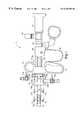
- FIG. 1is an elevational side view of a resectoscope incorporating features of the present invention
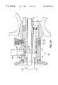
- FIG. 1Ais an enlarged partial cross-sectional view of a portion of the resectoscope shown in FIG. 1;
- FIG. 1Bis an enlarged partial cross-sectional view of a portion of an alternate embodiment of the resectoscope as shown in FIG. 1A;
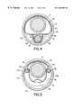
- FIG. 2is a cross-sectional view of the resectoscope shown in FIG. 1A taken along line 2 — 2 ;
- FIG. 3is a cross-sectional view of the resectoscope shown in FIG. 1A taken along line 3 — 3 ;
- FIG. 4is a cross-sectional view of the resectoscope shown in FIG. 1 taken along line 4 — 4 ;
- FIG. 5is a cross-sectional view of the resectoscope shown in FIG. 1 taken along line 5 — 5 ;
- FIG. 6is a cross-sectional view of an alternate embodiment of the front end of the outer sheath assembly.
- FIG. 1there is shown an elevational side view of a resectoscope 10 incorporating features of the present invention.
- a resectoscope 10incorporating features of the present invention.
- the present inventionwill be described with reference to the embodiments shown in the drawings, it should be understood that the present invention can be embodied in many alternate forms of embodiments.
- any suitable size, shape or type of elements or materialscould be used.
- the present inventionis being described with reference to a resectoscope, features of the present invention could be used with any suitable type of endoscope.
- the resectoscope 10generally comprises a working element 12 , a telescope 14 , a sheath assembly 16 and a throughput device 18 .
- the throughput deviceis a tool, such as an electrode or a fiber optic laser guide.
- the telescope 14in the embodiment shown is a U.S.A. ELITE SYSTEM telescope.
- U.S.A. ELITE SYSTEMis a trademark of Circon Corporation of Goleta, California.
- the telescope 14is removably mounted to the working element 12 , and has a connector 20 for connecting fiber optics in the telescope with a light source by means of a flexible light transmitting cable (not shown).
- the telescope 14is well known in the art. In alternate embodiments, any suitable type of telescope and/or throughput device could be used.
- the working element 12generally comprises a frame 22 , a movable portion 26 , and a latch assembly 28 .
- the frame 22generally comprises a front handle 24 , a rear section 30 , a guide bar 32 , a telescope guide tube 34 and a front section 36 .
- the front and rear sections 36 , 30are connected to each other by the guide bar 32 and the telescope guide tube 34 .
- the movable portion 26is slidingly mounted on the guide bar 32 and the telescope guide tube 34 between the rear position shown in FIG. 1 and a forward position against the rear end of the front handle 24 .
- a spring 38biases the movable portion 26 in the rear position. Any suitable movable portion could be provided, such as described in U.S. Pat. No.
- the telescope guide tube 34extends through the front section 36 to a front end of the resectoscope.
- the guide tube 34includes three fluid entry holes 40 at the front section 36 .
- any suitable fluid entrycould be provided in the tube 34 at the front section 36 .
- the rear end of the tube 34is open for introduction and removal of the telescope 14 .
- the rear section 30preferably comprises a seal (not shown) to seal the rear end of the tube 34 with the telescope 14 .
- the telescope guide tube 34is provided with a non-uniform cross-sectional shape along its length.
- the tube 34has a front section 42 and a section 44 .
- the section 44preferably extends at least from the fluid entry holes 40 to the front section 42 .
- the section 44also extends to the rear section 30 .
- the tube 34could have a different cross-sectional shape rearward from the front section 36 .
- the section 44has a general D-shaped cross-section as best seen in FIG. 4 .
- any suitable shapecould be provided.
- the front section 42as best seen in FIG.
- the front section 42could be provided with any suitable cross-sectional shape.
- the cross-sectional area 52 defined within the section 44is larger than the cross-sectional area 54 defined within the front section 42 .
- the elongate shaft of the telescopefits snuggly against the interior side walls of the tube 34 at the front section 42 proximate the concave recesses 46 , 48 and the top side of the tube 34 .
- the concave recesses 46 , 48form guide stabilizers for slidingly capturing arms 56 , 58 of the electrode 18 at the front end of the electrode.
- the electrode 18does not need its own separate stabilizer as in the prior art.
- the stabilization functionis integrated into the front section 42 .
- the bottom recess 50also functions as a guide stabilizer for the main shaft 60 of the electrode 18 as the electrode is longitudinally extended and retracted when the movable portion 26 is moved.
- the tube 34is preferably a one-piece metal member, there is preferably a smooth transition between the two sections 42 , 44 .
- the frame 22also preferably comprises an elongate electrode guide member 62 .
- the guide member 62is fixedly attached directly to the bottom flat side 36 of the telescope guide tube section 44 along a majority of the length of the tube section 44 between the front section 36 and the front section 42 .
- the guide member 62preferably has a general U-shaped cross-section with its ends 64 attached to the side 35 .
- the guide member 62 and side 35 of the tube 34thus, form an electrode passage 66 for a portion of the main shaft 60 of the electrode 18 .
- the electrode passage 66 and area 52share a common wall at side 35 .
- This common wall configurationhelps to reduce the cross-sectional size of the instrument because it is smaller than a double wall.
- any suitable type or shape of guide member or memberscould be provided.
- the front section 36comprises an electrode guide channel 68 .
- An annular bearing channel 70fluid conduits 72 with an annular groove 74 and seals 76 , such as O-rings.
- An O-ring seal 78is located in the electrode guide channel 68 for sealing off the rear end of the channel 68 with the electrode 18 .
- Ball bearings 80are located in the annular bearing channel 70 to rotatably mount the connector 28 to the front section 36 .
- the fluid conduits 72are aligned with the holes 40 in the telescope guide tube 34 .
- the seals 76make a sealing engagement between the front section 36 and the connector 28 around the annular groove 74 into the conduits 72 .
- the connector 28generally comprises a first ring-shaped member 82 , a second ring shaped member 84 , a plunger 86 , a spring 88 , and two guides 90 , 92 .
- the two guides 90 , 92are fixedly attached to the inner member 82 .
- the inner member 82is rotatably connected to the front section 36 of the frame 22 by the bearings 80 .
- the interaction of the bearings 80 with the bearing channel 70 and the bearing seating holes 94 in the inner member 82prevents the inner member 82 from longitudinally moving along the length of the front section 36 .
- the seals 76make a sealing engagement with the underside of the inner member 82 .
- the inner member 82also comprises a front cone shaped section 96 with a fluid hole 98 therethrough.
- the fluid hole 98is aligned with the annular groove 74 in the front section 36 .
- the outer member 84is located around the rear end of the inner member 82 .
- the plunger 86is attached to the outer member 84 .
- the outer member 84has holes through it with the two guides 90 , 92 located in the holes.
- the spring 88is located between the guide 90 and the plunger 86 to bias the outer member 84 in an upward direction relative to the inner member 82 as shown in FIG. 2 .
- the area 100 inside the outer member 84is larger than the inner member 82 such that the outer member can be moved relative to the inner member 82 , as indicated by arrow A, with the spring 88 being compressed and the outer member 84 sliding on the guides 90 , 92 .
- the outer member 84comprises two forward extending lateral side arms 102 with outwardly extending latch pins 104 (see FIG. 1) on opposite sides of the outer member 84 .
- the pins 104are moved up and down.
- the spring 88returns the outer member 84 and pins 104 to an upward position when the plunger 86 is released by the user.
- the outer sheath assembly 16generally comprises a single tube 106 , a single connector 108 at the rear end of the tube 106 , and an insulating tip 110 at the front end of the tube 106 .
- the tube 106forms an outer tube for the shaft.
- the tube 106is preferably comprised of metal with a general circular ring shaped cross-section.
- the front end 112 of the tube 106is slightly enlarged with holes 114 through the side wall of the tube.
- the insulating tip 110is preferably comprised of dielectric material such as ceramic.
- the insulating tip 110is generally ring shaped and extends into the front end of the tube 106 .
- the tip 110is preferably glued or bonded and also mechanically retained to the tube 106 by dimples 116 .
- the connector 108generally comprises a frame 118 and two fluid conduit mounts 120 , 122 .
- the frame 118includes a cone shaped receiving area 124 extending into its rear end, two areas 126 , 128 for mounting the fluid mounts 120 , 122 for access into the receiving area 124 , and two side latch areas 130 , 132 for receiving the arms 102 and pins 104 of the connector 28 .
- the two fluid mounts 120 , 122each include a stopcock 134 .
- the area 53 between the outside surface of the telescope guide tube 34 and the inside of the outer sheath tube 106forms a fluid outflow channel or passage.
- a continuous flow resectoscopeis provided without the sheath assembly having two tubes; an inner tube and an outer tube.
- the sheath assembly 16only comprises the outer tube 106 and the telescope guide tube 34 of the frame 22 is used to perform the function of the prior art sheath assembly inner tube. This allows the cross-sectional area of the resectoscope shaft to be reduced because of the elimination of the sheath assembly inner tube.
- the distance D between the front end of the front section 36 of the frame 22 and the rear end of the outer sheath tube 106is smaller than in the prior art because of the elimination of the prior art inner sheath assembly and its rear connector.
- the outer sheath assembly connector 108is directly connected to the connector 28 on the frame 22 without an intermediate connector therebetween. This allows the sheath assembly 16 to be longer than in the prior art while still allowing same length electrodes 18 to be used as in the prior art resectoscopes; the electrodes merely being manufactured without the prior art stabilizer being attached.
- the extra working length of the resectoscopes, from the washer 25 to the distal tip 27could be increased by about 0.75 inch while using the same length telescope and electrodes as in the prior art.
- a longer length resectoscope shaftcan be easier to use; especially with obese patients.
- the most expensive part of the resectoscopeis the telescope 14 . Therefore, in designing a new resectoscope it is desirable to have the new resectoscope be able to use a current telescope that the user already owns.
- Two sizes of telescopesinclude 4 mm and 3 mm sizes.,the 4 mm size telescope is presently used in a continuous flow resectoscope having resectoscope sheath outer diameters of about 25 French and 27 French.
- Such prior art resectoscopesuse sheath assemblies that have an inner tube and an outer tube. With the present invention, the prior art 4 mm telescope can be used with the sheath assembly 16 having an outer diameter of only about 22 French.
- the flow of fluid through the areas 52 , 53 , 54will be about 90% or higher as provided in the prior art 25 / 27 French design which should be sufficient to provide good removal of blood and debris from the field of view of the user.
- the relative percentagewould be much lower if the prior art inner sheath tube was still present.
- the outer diameter of resectoscope shaftcould be reduced to about 20 French while retaining about 90% of the flow rate Q as in the prior art.
- the smaller outer diameter of the resectoscope shaftcan be easier for the user to insert and less painful to the patient.
- the reduced cross-sectional flow area 54 at the front end of the telescope guide tube 34causes an increase in velocity of the inflowing fluid as the fluid is discharged from the front end of the resectoscope.
- This increased velocity fluid at the distal tip of the telescope 14clears away blood and debris from the user's field of view more quickly than in the prior art even with the 10% reduction in the incoming fluid flow rate.
- the present inventionalso moves the inflow closer to the end of the telescope than in the prior art to increase the cleaning of the field of view.
- the present inventionalso overcomes a problem in the prior art in regard to the insulating tip.
- an insulting tip made of ceramic materialwas provided at the distal end of the inner sheath.
- torque applied to the inner sheathresulted in the insulating tip cracking.
- Pieces of the tipcould break off inside the patient.
- the insulating tipcan be mounted directly to the outer sheath. Therefore, this eliminates torque forces on the insulating tip, and resultant cracking, that existed in the inner/outer sheath assembly in the prior art.
- the tube 106 ′includes the holes 114 and additional holes 114 ′.
- the holes 114 ′include indented sections 115 ′.
- the insulating tip 110 ′includes holes 111 ′.
- the indented sections 115 ′project into the holes 111 ′ to mechanically attach the tube 106 ′ to the tip 110 ′ and, the holes 114 ′ and 111 ′ also function, similar to holes 114 , as outlets through the side of the outer sheath for the outflow of fluid and debris from inside the patient.
- the resectoscopecan have a larger combined area of outflow side openings at its distal end than in the prior art.
- the connection of the tip 110 ′ to the tube 106 ′also preferably comprises a bonding or adhesive attachment.
- the present inventioncould also include an outflow channel through the insulated tip as disclosed in U.S. Pat. No. 5,807,240 which is hereby incorporated by reference in its entirety.
- the present inventionalso provides another advantage.
- the sheath assemblycomprises a movable latch as well as the working element having a movable latch.
- the continuous flow resectoscopecomprises only one movable latch 28 ; not two as in the prior art continuous flow resectoscopes. Therefore, the continuous flow resectoscope of the present invention is less expensive to manufacture than the prior art and is also less complicated to clean.
- the present inventionalso provides another advantage. Even though the outside diameter of the outer sheath 16 is being reduced to about 22 French along most of its length, the resectoscope 10 is still able to use electrodes (less an electrode stabilizer) which were originally designed for the 25 French instrument. These 25 French electrodes have a working end at their distal tips that are larger than electrodes designed for a 22 French instrument having an inner/outer sheath design. The 25 French electrode can remove more tissue in a single swipe then a 22 French electrode having a smaller working end. Therefore, the present invention also allows the user to remove tissue faster than use of a conventional design. Features of the present invention could also be used with a non-continuous flow outer sheath with a single fluid mount feeding fluid into both areas 52 , 53 .
- FIG. 1Bshows an alternate embodiment of the present invention.
- the endoscope 200comprises the working element 12 , the telescope 14 (not shown in this view for the sake of clarity), and a single sheath assembly 202 .
- the sheath assembly 202is substantially similar to the sheath assembly 16 , but comprises a single fluid conduit mount 204 rather than two fluid conduit mounts.
- the fluid flow passages 206 , 208 through the respective mount 204 and the rear end connector frame 210extend into areas 98 and 124 .
- fluid from the mount 204can flow into areas 98 and 124 .
- fluid from the mount 204can flow into both tubes 34 , 106 as indicated by arrows Y 1 and Y 2 to the distal end of the endoscope.
- This type of embodimentcan be used for a non-continuous flow resectoscope.
Landscapes
- Health & Medical Sciences (AREA)
- Life Sciences & Earth Sciences (AREA)
- Surgery (AREA)
- Engineering & Computer Science (AREA)
- Physics & Mathematics (AREA)
- Veterinary Medicine (AREA)
- Public Health (AREA)
- Nuclear Medicine, Radiotherapy & Molecular Imaging (AREA)
- Biomedical Technology (AREA)
- Heart & Thoracic Surgery (AREA)
- Medical Informatics (AREA)
- Molecular Biology (AREA)
- Animal Behavior & Ethology (AREA)
- General Health & Medical Sciences (AREA)
- Otolaryngology (AREA)
- Optics & Photonics (AREA)
- Plasma & Fusion (AREA)
- Electromagnetism (AREA)
- Biophysics (AREA)
- Pathology (AREA)
- Radiology & Medical Imaging (AREA)
- Surgical Instruments (AREA)
- Endoscopes (AREA)
Abstract
Description
Claims (11)
Priority Applications (1)
| Application Number | Priority Date | Filing Date | Title |
|---|---|---|---|
| US09/387,993US6358200B1 (en) | 1999-09-01 | 1999-09-01 | Continuous flow resectoscope with single tube sheath assembly and rotatable connection |
Applications Claiming Priority (1)
| Application Number | Priority Date | Filing Date | Title |
|---|---|---|---|
| US09/387,993US6358200B1 (en) | 1999-09-01 | 1999-09-01 | Continuous flow resectoscope with single tube sheath assembly and rotatable connection |
Publications (1)
| Publication Number | Publication Date |
|---|---|
| US6358200B1true US6358200B1 (en) | 2002-03-19 |
Family
ID=23532179
Family Applications (1)
| Application Number | Title | Priority Date | Filing Date |
|---|---|---|---|
| US09/387,993Expired - LifetimeUS6358200B1 (en) | 1999-09-01 | 1999-09-01 | Continuous flow resectoscope with single tube sheath assembly and rotatable connection |
Country Status (1)
| Country | Link |
|---|---|
| US (1) | US6358200B1 (en) |
Cited By (82)
| Publication number | Priority date | Publication date | Assignee | Title |
|---|---|---|---|---|
| US20020183589A1 (en)* | 2000-08-26 | 2002-12-05 | Pieter Brommersma | Urological resectoscope comprising a contacting device |
| US6527707B1 (en)* | 1999-06-22 | 2003-03-04 | Olympus Winter & Ibe Gmbh | Endoscope with a working passage |
| US20030125607A1 (en)* | 2001-12-28 | 2003-07-03 | Richard Wolf Gmbh | Hysteroscope with a shank exchange system |
| WO2003057020A1 (en)* | 2002-01-07 | 2003-07-17 | Acmi Corporation | Outflow system for an endoscope |
| US6645140B2 (en)* | 2000-11-15 | 2003-11-11 | Olympus Winter & Ibe Gmbh | Continuously rinsing double-sheath endoscope |
| US6682477B2 (en)* | 2000-02-25 | 2004-01-27 | Richard Wolf Gmbh | Hysteroscope |
| WO2004032732A1 (en)* | 2002-09-12 | 2004-04-22 | Olympus Winter & Ibe Gmbh | Removable resectoscope provided with an external shaft |
| US20050021010A1 (en)* | 2002-11-20 | 2005-01-27 | Aesculap Ag & Co. Kg | Endoscope |
| US20050038323A1 (en)* | 2003-08-11 | 2005-02-17 | Knit Ventures, Llc | Tear duct endoscope for medication and sampling |
| US20050049459A1 (en)* | 2003-06-20 | 2005-03-03 | Soren Hern | Endoscopic attachment device |
| WO2005016181A3 (en)* | 2003-08-04 | 2005-04-14 | Vision Sciences Inc | Sheath with channel for endoscope |
| EP1523932A1 (en)* | 2003-10-17 | 2005-04-20 | Henke-Sass, Wolf GmbH | Endoscope |
| US20050253692A1 (en)* | 2004-05-13 | 2005-11-17 | Nadine Lukes-Dyer | Baby in Car Alert |
| US20060047185A1 (en)* | 2004-08-27 | 2006-03-02 | Cemal Shener | Tissue resecting system |
| EP1637065A1 (en)* | 2004-09-21 | 2006-03-22 | Richard Wolf GmbH | Endoscopic instrument |
| US20060206004A1 (en)* | 2004-09-06 | 2006-09-14 | Olympus Winter & Ibe Gmbh | Ureteroscope having a stem |
| EP1752107A1 (en)* | 2005-08-12 | 2007-02-14 | Karl Storz GmbH & Co. KG | Medical instrument |
| JP2007506463A (en)* | 2003-06-20 | 2007-03-22 | コンチュラ ソシエテ アノニム | Endoscope mounting device |
| US20070185383A1 (en)* | 2006-02-08 | 2007-08-09 | Vision-Sciences, Inc. | Tapered endoscopic protective sheath |
| US20070250038A1 (en)* | 2006-04-20 | 2007-10-25 | Boston Scientific Scimed, Inc. | Multiple lumen assembly for use in endoscopes or other medical devices |
| US20080015621A1 (en)* | 1997-09-04 | 2008-01-17 | Smith & Nephew, Inc. | Surgical endoscopic cutting device and method for its use |
| WO2009065564A3 (en)* | 2007-11-20 | 2009-08-20 | Winter & Ibe Olympus | Urological resectoscope comprising holes |
| US20090295129A1 (en)* | 2008-05-22 | 2009-12-03 | Cosco Management, Inc. | Folding stroller with roller element-assisted folding |
| US20100145142A1 (en)* | 2008-10-07 | 2010-06-10 | Neurendo B.V. | Minimal invasive neurosurgery assembly as well as a method for neurosurgery using such a neurosurgery assembly |
| US20110144429A1 (en)* | 2009-12-14 | 2011-06-16 | C2Cure Inc. | Endoscope with an improved working channel |
| WO2011150111A1 (en)* | 2010-05-28 | 2011-12-01 | Gyrus Acmi, Inc. | Continuous flow endoscope system |
| US20130267780A1 (en)* | 2007-02-19 | 2013-10-10 | Ingoscope Systems Gmbh | Tube assembly for an endoscope |
| WO2014026028A1 (en)* | 2012-08-10 | 2014-02-13 | Attenuex Technologies, Inc. | Systems for performing a medical procedure |
| US20140352483A1 (en)* | 2013-06-04 | 2014-12-04 | General Electric Company | Remote alignment tool |
| DE102013022121A1 (en) | 2013-12-18 | 2015-06-18 | Olympus Winter & Ibe Gmbh | Transporter for controlling the longitudinal displacement of an electrode |
| US9060800B1 (en) | 2001-10-26 | 2015-06-23 | Smith & Nephew, Inc. | Reciprocating rotary arthroscopic surgical instrument |
| US9155454B2 (en) | 2010-09-28 | 2015-10-13 | Smith & Nephew, Inc. | Hysteroscopic system |
| WO2016185102A1 (en) | 2015-05-20 | 2016-11-24 | Ab Medica | Device for resecting an organ in a cavity of a body |
| US20170100016A1 (en)* | 2015-10-12 | 2017-04-13 | Covidien Lp | Continuous flow scope configuration with optional tool usage |
| US9820719B2 (en) | 2008-06-19 | 2017-11-21 | Cogentix Medical, Inc. | Method and system for intrabody imaging |
| US20170340192A1 (en)* | 2016-05-26 | 2017-11-30 | Covidien Lp | Continuous flow endoscope |
| US20180078125A1 (en)* | 2015-06-22 | 2018-03-22 | Olympus Winter & Ibe Gmbh | Surgical instrument, in particular ureteroscope |
| US10244928B2 (en) | 2007-09-05 | 2019-04-02 | Cogentix Medical, Inc. | Compact endoscope tip and method for constructing same |
| CN109620394A (en)* | 2018-12-29 | 2019-04-16 | 广东德弘医疗设备有限公司 | A kind of electric prostate-cutting mirror |
| US10299819B2 (en) | 2016-07-28 | 2019-05-28 | Covidien Lp | Reciprocating rotary surgical cutting device and system for tissue resecting, and method for its use |
| US10299803B2 (en) | 2016-08-04 | 2019-05-28 | Covidien Lp | Self-aligning drive coupler |
| US10327880B2 (en) | 2000-04-14 | 2019-06-25 | Attenuex Technologies, Inc. | Attenuation device for use in an anatomical structure |
| US10383510B2 (en) | 2000-04-14 | 2019-08-20 | Solace Therapeutics, Inc. | Implant with high vapor pressure medium |
| US10631889B2 (en) | 2014-12-16 | 2020-04-28 | Covidien Lp | Surgical device with incorporated tissue extraction |
| DE102018129904A1 (en)* | 2018-11-27 | 2020-05-28 | Olympus Winter & Ibe Gmbh | Resectoscope with an electrode instrument in the outer shaft |
| US10750931B2 (en) | 2015-05-26 | 2020-08-25 | Covidien Lp | Systems and methods for generating a fluid bearing for an operative procedure |
| US10772654B2 (en) | 2017-03-02 | 2020-09-15 | Covidien Lp | Fluid-driven tissue resecting instruments, systems, and methods |
| US10772652B2 (en) | 2015-01-28 | 2020-09-15 | Covidien Lp | Tissue resection system |
| US10799264B2 (en) | 2015-06-18 | 2020-10-13 | Covidien Lp | Surgical instrument with suction control |
| US10804769B2 (en) | 2015-06-17 | 2020-10-13 | Covidien Lp | Surgical instrument with phase change cooling |
| US10842350B2 (en) | 2015-06-17 | 2020-11-24 | Covidien Lp | Endoscopic device with drip flange and methods of use thereof for an operative procedure |
| US10869684B2 (en) | 2018-02-13 | 2020-12-22 | Covidien Lp | Powered tissue resecting device |
| US10898218B2 (en) | 2019-02-25 | 2021-01-26 | Covidien Lp | Tissue resecting device including a motor cooling assembly |
| EP3772318A1 (en)* | 2019-08-06 | 2021-02-10 | Delmont Imaging SAS | Hysteroscope |
| US10945752B2 (en) | 2019-03-20 | 2021-03-16 | Covidien Lp | Tissue resecting instrument including a rotation lock feature |
| EP3827775A1 (en) | 2019-11-29 | 2021-06-02 | Olympus Winter & Ibe GmbH | Transporter with locking device |
| CN112998843A (en)* | 2019-12-20 | 2021-06-22 | 奥林匹斯冬季和Ibe有限公司 | Resectoscope with distal electrode guidance |
| US11065147B2 (en) | 2018-10-18 | 2021-07-20 | Covidien Lp | Devices, systems, and methods for pre-heating fluid to be introduced into a patient during a surgical procedure |
| US11083481B2 (en) | 2019-02-22 | 2021-08-10 | Covidien Lp | Tissue resecting instrument including an outflow control seal |
| US11154318B2 (en) | 2019-02-22 | 2021-10-26 | Covidien Lp | Tissue resecting instrument including an outflow control seal |
| US11179172B2 (en) | 2019-12-05 | 2021-11-23 | Covidien Lp | Tissue resecting instrument |
| US11197710B2 (en) | 2018-10-26 | 2021-12-14 | Covidien Lp | Tissue resecting device including a blade lock and release mechanism |
| US11197981B2 (en) | 2019-02-07 | 2021-12-14 | Solace Therapeutics, Inc. | Pressure attenuation device |
| CN113940749A (en)* | 2020-07-17 | 2022-01-18 | 奥林匹斯冬季和Ibe有限公司 | Surgical hand-held instrument, insulating insert therefor and method of operating a surgical hand-held instrument |
| US11317947B2 (en) | 2020-02-18 | 2022-05-03 | Covidien Lp | Tissue resecting instrument |
| US11324526B2 (en) | 2018-02-02 | 2022-05-10 | Calyxo, Inc. | Devices and methods for minimally invasive kidney stone removal by combined aspiration and irrigation |
| US11376032B2 (en) | 2019-12-05 | 2022-07-05 | Covidien Lp | Tissue resecting instrument |
| US11452806B2 (en) | 2019-10-04 | 2022-09-27 | Covidien Lp | Outflow collection vessels, systems, and components thereof for hysteroscopic surgical procedures |
| US11547815B2 (en) | 2018-05-30 | 2023-01-10 | Covidien Lp | Systems and methods for measuring and controlling pressure within an internal body cavity |
| US11547782B2 (en) | 2020-01-31 | 2023-01-10 | Covidien Lp | Fluid collecting sheaths for endoscopic devices and systems |
| US11553977B2 (en) | 2019-05-29 | 2023-01-17 | Covidien Lp | Hysteroscopy systems and methods for managing patient fluid |
| US20230026445A1 (en)* | 2015-02-27 | 2023-01-26 | Covidien Lp | Oblique tip endoscope with zero degree field angle |
| US11571233B2 (en) | 2020-11-19 | 2023-02-07 | Covidien Lp | Tissue removal handpiece with integrated suction |
| US11596429B2 (en) | 2020-04-20 | 2023-03-07 | Covidien Lp | Tissue resecting instrument |
| US11737777B2 (en) | 2020-02-05 | 2023-08-29 | Covidien Lp | Tissue resecting instruments |
| US11883058B2 (en) | 2019-03-26 | 2024-01-30 | Covidien Lp | Jaw members, end effector assemblies, and ultrasonic surgical instruments including the same |
| US11890237B2 (en) | 2019-10-04 | 2024-02-06 | Covidien Lp | Outflow collection vessels, systems, and components thereof for hysteroscopic surgical procedures |
| US12156673B2 (en) | 2020-10-07 | 2024-12-03 | Covidien Lp | Temperature measurement device for a handpiece of a surgical instrument |
| US12256989B2 (en) | 2022-09-29 | 2025-03-25 | Calyxo, Inc. | Tool guiding device for kidney stone treatment apparatus |
| US12303109B2 (en) | 2021-12-22 | 2025-05-20 | Covidien Lp | Surgical systems and methods for component cooling while warming fluid to be introduced during a surgical procedure |
| US12329396B2 (en) | 2022-03-02 | 2025-06-17 | Calyxo, Inc. | Kidney stone treatment system |
| US12364500B2 (en) | 2021-05-26 | 2025-07-22 | Covidien Lp | Tissue resecting instrument |
Citations (10)
| Publication number | Priority date | Publication date | Assignee | Title |
|---|---|---|---|---|
| US3835842A (en)* | 1972-07-03 | 1974-09-17 | J Iglesias | Endoscope with continuous irrigation |
| US3850175A (en)* | 1972-07-03 | 1974-11-26 | J Lglesias | Resectoscope with continuous irrigation |
| US3850162A (en)* | 1972-07-03 | 1974-11-26 | J Iglesias | Endoscope with continuous irrigation |
| US4423727A (en)* | 1981-04-10 | 1984-01-03 | Jerrold Widran | Continuous flow urological endoscopic apparatus and method of using same |
| US4726370A (en)* | 1985-02-09 | 1988-02-23 | Olympus Optical Co., Ltd. | Resectoscope device |
| US4920961A (en) | 1988-06-02 | 1990-05-01 | Circon Corporation | System for disconnetably mounting an endoscope sheath with an endoscope tool |
| US5131382A (en)* | 1989-03-27 | 1992-07-21 | Meyer William F | Endoscopic percutaneous discectomy device |
| US5486155A (en)* | 1994-07-15 | 1996-01-23 | Circon Corporation | Rotatable endoscope sheath |
| US5807240A (en)* | 1996-09-24 | 1998-09-15 | Circon Corporation | Continuous flow endoscope with enlarged outflow channel |
| US5857962A (en) | 1997-03-13 | 1999-01-12 | Circon Corporation | Resectoscope with curved electrode channel and resiliently deflectable electrode section |
- 1999
- 1999-09-01USUS09/387,993patent/US6358200B1/ennot_activeExpired - Lifetime
Patent Citations (10)
| Publication number | Priority date | Publication date | Assignee | Title |
|---|---|---|---|---|
| US3835842A (en)* | 1972-07-03 | 1974-09-17 | J Iglesias | Endoscope with continuous irrigation |
| US3850175A (en)* | 1972-07-03 | 1974-11-26 | J Lglesias | Resectoscope with continuous irrigation |
| US3850162A (en)* | 1972-07-03 | 1974-11-26 | J Iglesias | Endoscope with continuous irrigation |
| US4423727A (en)* | 1981-04-10 | 1984-01-03 | Jerrold Widran | Continuous flow urological endoscopic apparatus and method of using same |
| US4726370A (en)* | 1985-02-09 | 1988-02-23 | Olympus Optical Co., Ltd. | Resectoscope device |
| US4920961A (en) | 1988-06-02 | 1990-05-01 | Circon Corporation | System for disconnetably mounting an endoscope sheath with an endoscope tool |
| US5131382A (en)* | 1989-03-27 | 1992-07-21 | Meyer William F | Endoscopic percutaneous discectomy device |
| US5486155A (en)* | 1994-07-15 | 1996-01-23 | Circon Corporation | Rotatable endoscope sheath |
| US5807240A (en)* | 1996-09-24 | 1998-09-15 | Circon Corporation | Continuous flow endoscope with enlarged outflow channel |
| US5857962A (en) | 1997-03-13 | 1999-01-12 | Circon Corporation | Resectoscope with curved electrode channel and resiliently deflectable electrode section |
Cited By (183)
| Publication number | Priority date | Publication date | Assignee | Title |
|---|---|---|---|---|
| US9226650B2 (en) | 1997-09-04 | 2016-01-05 | Smith & Nephew, Inc. | Surgical cutting device and method for its use |
| US20080058842A1 (en)* | 1997-09-04 | 2008-03-06 | Smith & Nephew, Inc. | Surgical endoscopic cutting device and method for its use |
| US9427247B2 (en) | 1997-09-04 | 2016-08-30 | Smith & Nephew, Inc. | Surgical cutting device and method for its use |
| US9226765B2 (en) | 1997-09-04 | 2016-01-05 | Smith & Nephew, Inc. | Surgical cutting device and method for its use |
| US9089358B2 (en) | 1997-09-04 | 2015-07-28 | Smith & Nephew, Inc. | Surgical cutting device and method for its use |
| US8061359B2 (en) | 1997-09-04 | 2011-11-22 | Smith & Nephew, Inc. | Surgical endoscopic cutting device and method for its use |
| US20080015621A1 (en)* | 1997-09-04 | 2008-01-17 | Smith & Nephew, Inc. | Surgical endoscopic cutting device and method for its use |
| US20080058588A1 (en)* | 1997-09-04 | 2008-03-06 | Smith & Nephew, Inc. | Surgical endoscopic cutting device and method for its use |
| US9750520B2 (en) | 1997-09-04 | 2017-09-05 | Covidien Lp | Surgical endoscopic cutting device and method for its use |
| US8893722B2 (en) | 1997-09-04 | 2014-11-25 | Smith & Nephew, Inc. | Surgical endoscopic cutting device and method for its use |
| US6527707B1 (en)* | 1999-06-22 | 2003-03-04 | Olympus Winter & Ibe Gmbh | Endoscope with a working passage |
| US6682477B2 (en)* | 2000-02-25 | 2004-01-27 | Richard Wolf Gmbh | Hysteroscope |
| US10383510B2 (en) | 2000-04-14 | 2019-08-20 | Solace Therapeutics, Inc. | Implant with high vapor pressure medium |
| US10327880B2 (en) | 2000-04-14 | 2019-06-25 | Attenuex Technologies, Inc. | Attenuation device for use in an anatomical structure |
| US20020183589A1 (en)* | 2000-08-26 | 2002-12-05 | Pieter Brommersma | Urological resectoscope comprising a contacting device |
| US6746395B2 (en)* | 2000-08-26 | 2004-06-08 | Olympus Winter & Ibe Gmbh | Urological resectoscope comprising a contacting device |
| US6645140B2 (en)* | 2000-11-15 | 2003-11-11 | Olympus Winter & Ibe Gmbh | Continuously rinsing double-sheath endoscope |
| US9066745B2 (en) | 2001-10-26 | 2015-06-30 | Smith & Nephew, Inc. | Reciprocating rotary arthroscopic surgical instrument |
| US9060801B1 (en) | 2001-10-26 | 2015-06-23 | Smith & Nephew, Inc. | Reciprocating rotary arthroscopic surgical instrument |
| US9060800B1 (en) | 2001-10-26 | 2015-06-23 | Smith & Nephew, Inc. | Reciprocating rotary arthroscopic surgical instrument |
| US9636130B2 (en) | 2001-10-26 | 2017-05-02 | Covidien Lp | Reciprocating rotary arthroscopic surgical instrument |
| US10441306B2 (en) | 2001-10-26 | 2019-10-15 | Covidien Lp | Reciprocating rotary arthroscopic surgical instrument |
| US7025720B2 (en)* | 2001-12-28 | 2006-04-11 | Richard Wolf Gmbh | Hysteroscope with a shank exchange system |
| US20030125607A1 (en)* | 2001-12-28 | 2003-07-03 | Richard Wolf Gmbh | Hysteroscope with a shank exchange system |
| US6712759B2 (en)* | 2002-01-07 | 2004-03-30 | Acmi Corporation | Outflow system for an endoscope |
| WO2003057020A1 (en)* | 2002-01-07 | 2003-07-17 | Acmi Corporation | Outflow system for an endoscope |
| WO2004032732A1 (en)* | 2002-09-12 | 2004-04-22 | Olympus Winter & Ibe Gmbh | Removable resectoscope provided with an external shaft |
| GB2408942B (en)* | 2002-09-12 | 2006-05-24 | Winter & Ibe Olympus | Resectoscope provided with a removable external shaft |
| GB2408942A (en)* | 2002-09-12 | 2005-06-15 | Winter & Ibe Olympus | Removable resectoscope provided with an external shaft |
| US20050021010A1 (en)* | 2002-11-20 | 2005-01-27 | Aesculap Ag & Co. Kg | Endoscope |
| US7615002B2 (en)* | 2002-11-20 | 2009-11-10 | Aesculap Ag | Endoscope |
| JP2007506463A (en)* | 2003-06-20 | 2007-03-22 | コンチュラ ソシエテ アノニム | Endoscope mounting device |
| US20050049459A1 (en)* | 2003-06-20 | 2005-03-03 | Soren Hern | Endoscopic attachment device |
| US7758497B2 (en)* | 2003-06-20 | 2010-07-20 | Contura A/S | Endoscopic attachment device |
| US20070142709A1 (en)* | 2003-08-04 | 2007-06-21 | Vision-Sciences, Inc. | Sheath with channel for endoscope |
| WO2005016181A3 (en)* | 2003-08-04 | 2005-04-14 | Vision Sciences Inc | Sheath with channel for endoscope |
| US20050038323A1 (en)* | 2003-08-11 | 2005-02-17 | Knit Ventures, Llc | Tear duct endoscope for medication and sampling |
| US20050085692A1 (en)* | 2003-10-17 | 2005-04-21 | Ralf Kiehn | Endoscope |
| EP1523932A1 (en)* | 2003-10-17 | 2005-04-20 | Henke-Sass, Wolf GmbH | Endoscope |
| US20050253692A1 (en)* | 2004-05-13 | 2005-11-17 | Nadine Lukes-Dyer | Baby in Car Alert |
| US20060047185A1 (en)* | 2004-08-27 | 2006-03-02 | Cemal Shener | Tissue resecting system |
| WO2006026236A3 (en)* | 2004-08-27 | 2006-09-14 | Smith & Nephew Inc | Tissue resecting system |
| US8062214B2 (en) | 2004-08-27 | 2011-11-22 | Smith & Nephew, Inc. | Tissue resecting system |
| US8419626B2 (en) | 2004-08-27 | 2013-04-16 | Smith & Nephew, Inc. | Tissue resecting system |
| US9936861B2 (en) | 2004-08-27 | 2018-04-10 | Covidien Lp | Tissue resecting system |
| US10939810B2 (en) | 2004-08-27 | 2021-03-09 | Covidien Lp | Tissue resecting system |
| JP2012213639A (en)* | 2004-08-27 | 2012-11-08 | Smith & Nephew Inc | Tissue resecting system |
| JP2008511397A (en)* | 2004-08-27 | 2008-04-17 | スミス アンド ネフュー インコーポレーテッド | Tissue resection system |
| US9125550B2 (en) | 2004-08-27 | 2015-09-08 | Smith & Nephew, Inc. | Tissue resecting system |
| US10076237B2 (en) | 2004-08-27 | 2018-09-18 | Covidien Lp | Tissue resecting system |
| US8852085B2 (en) | 2004-08-27 | 2014-10-07 | Smith & Nephew, Inc. | Tissue resecting system |
| US20060206004A1 (en)* | 2004-09-06 | 2006-09-14 | Olympus Winter & Ibe Gmbh | Ureteroscope having a stem |
| EP1637065A1 (en)* | 2004-09-21 | 2006-03-22 | Richard Wolf GmbH | Endoscopic instrument |
| US20060063975A1 (en)* | 2004-09-21 | 2006-03-23 | Richard Wolf Gmbh | Endoscopic instrument |
| US8118729B2 (en)* | 2004-09-21 | 2012-02-21 | Richard Wolf Gmbh | Endoscopic instrument having a rotatably mounted and detachable coupling part |
| US20070038215A1 (en)* | 2005-08-12 | 2007-02-15 | Martin Hahn | Medical instrument |
| US8702699B2 (en) | 2005-08-12 | 2014-04-22 | Karl Storz Gmbh & Co. Kg | Medical instrument |
| EP1752107A1 (en)* | 2005-08-12 | 2007-02-14 | Karl Storz GmbH & Co. KG | Medical instrument |
| US20070185383A1 (en)* | 2006-02-08 | 2007-08-09 | Vision-Sciences, Inc. | Tapered endoscopic protective sheath |
| US8202265B2 (en)* | 2006-04-20 | 2012-06-19 | Boston Scientific Scimed, Inc. | Multiple lumen assembly for use in endoscopes or other medical devices |
| US9358363B2 (en) | 2006-04-20 | 2016-06-07 | Boston Scientific Scimed, Inc. | Multiple lumen assembly for use in endoscopes or other medical devices |
| US20070250038A1 (en)* | 2006-04-20 | 2007-10-25 | Boston Scientific Scimed, Inc. | Multiple lumen assembly for use in endoscopes or other medical devices |
| US20130267780A1 (en)* | 2007-02-19 | 2013-10-10 | Ingoscope Systems Gmbh | Tube assembly for an endoscope |
| US9931019B2 (en)* | 2007-02-19 | 2018-04-03 | Ingoscope Systems Gmbh | Tube assembly for an endoscope |
| US10244928B2 (en) | 2007-09-05 | 2019-04-02 | Cogentix Medical, Inc. | Compact endoscope tip and method for constructing same |
| US10588497B2 (en) | 2007-09-05 | 2020-03-17 | Cogentix Medical, Inc. | Compact endoscope tip and method for constructing same |
| US11426061B2 (en) | 2007-09-05 | 2022-08-30 | Cogentix Medical, Inc. | Compact endoscope tip and method for constructing same |
| WO2009065564A3 (en)* | 2007-11-20 | 2009-08-20 | Winter & Ibe Olympus | Urological resectoscope comprising holes |
| US20100280314A1 (en)* | 2007-11-20 | 2010-11-04 | Pieter Brommersma | Urological resectoscope comprising holes |
| US20090295129A1 (en)* | 2008-05-22 | 2009-12-03 | Cosco Management, Inc. | Folding stroller with roller element-assisted folding |
| US9820719B2 (en) | 2008-06-19 | 2017-11-21 | Cogentix Medical, Inc. | Method and system for intrabody imaging |
| US11583245B2 (en) | 2008-06-19 | 2023-02-21 | Cogentix Medical, Inc. | Method and system for intrabody imaging |
| US20100145142A1 (en)* | 2008-10-07 | 2010-06-10 | Neurendo B.V. | Minimal invasive neurosurgery assembly as well as a method for neurosurgery using such a neurosurgery assembly |
| US8690761B2 (en)* | 2008-10-07 | 2014-04-08 | Neurendo B.V. | Minimal invasive neurosurgery assembly as well as a method for neurosurgery using such a neurosurgery assembly |
| US9138134B2 (en) | 2009-12-14 | 2015-09-22 | Gyrus Acmi, Inc. | Endoscope with an improved working channel |
| US20110144429A1 (en)* | 2009-12-14 | 2011-06-16 | C2Cure Inc. | Endoscope with an improved working channel |
| US8465421B2 (en) | 2009-12-14 | 2013-06-18 | C2Cure Inc. | Endoscope with an improved working channel |
| CN102905635B (en)* | 2010-05-28 | 2015-09-09 | 捷锐士阿希迈公司 | Continuous Flow Endoscopy System |
| US20110295066A1 (en)* | 2010-05-28 | 2011-12-01 | Gyrus Acmi, Inc. | Continuous flow endoscope systems |
| US9474438B2 (en)* | 2010-05-28 | 2016-10-25 | Gyrus Acmi, Inc. | Continuous flow endoscope systems |
| JP2013528073A (en)* | 2010-05-28 | 2013-07-08 | ジャイラス・エーシーエムアイ・インコーポレーテッド | Continuous flow endoscope system |
| WO2011150111A1 (en)* | 2010-05-28 | 2011-12-01 | Gyrus Acmi, Inc. | Continuous flow endoscope system |
| CN102905635A (en)* | 2010-05-28 | 2013-01-30 | 捷锐士阿希迈公司 | Continuous flow endoscope system |
| US12369788B2 (en) | 2010-09-28 | 2025-07-29 | Covidien Lp | Hysteroscopic system |
| US10251539B2 (en) | 2010-09-28 | 2019-04-09 | Covidien Lp | Hysteroscopic system |
| US11229354B2 (en) | 2010-09-28 | 2022-01-25 | Covidien Lp | Hysteroscopic system |
| US9155454B2 (en) | 2010-09-28 | 2015-10-13 | Smith & Nephew, Inc. | Hysteroscopic system |
| US11889993B2 (en) | 2010-09-28 | 2024-02-06 | Covidien Lp | Hysteroscopic system |
| WO2014026028A1 (en)* | 2012-08-10 | 2014-02-13 | Attenuex Technologies, Inc. | Systems for performing a medical procedure |
| US10531894B2 (en) | 2012-08-10 | 2020-01-14 | Solace Therapeutics, Inc. | Methods and systems for performing a medical procedure |
| US8864649B2 (en) | 2012-08-10 | 2014-10-21 | Attenuex Technologies, Inc. | Methods and systems for performing a medical procedure |
| US8882653B2 (en) | 2012-08-10 | 2014-11-11 | Attenuex Technologies, Inc. | Methods and systems for performing a medical procedure |
| US10799268B2 (en) | 2012-08-10 | 2020-10-13 | Solace Therapeutics, Inc. | Methods and systems for performing a medical procedure |
| US9801658B2 (en) | 2012-08-10 | 2017-10-31 | Attenuex Technologies, Inc. | Removal device |
| US10543071B2 (en) | 2012-08-10 | 2020-01-28 | Solace Therapeutics, Inc. | Methods and systems for performing a medical procedure |
| US8894563B2 (en) | 2012-08-10 | 2014-11-25 | Attenuex Technologies, Inc. | Methods and systems for performing a medical procedure |
| US8992412B2 (en) | 2012-08-10 | 2015-03-31 | Attenuex Technologies, Inc. | Removal device |
| US20140352483A1 (en)* | 2013-06-04 | 2014-12-04 | General Electric Company | Remote alignment tool |
| DE102013022121A1 (en) | 2013-12-18 | 2015-06-18 | Olympus Winter & Ibe Gmbh | Transporter for controlling the longitudinal displacement of an electrode |
| US10314637B2 (en) | 2013-12-18 | 2019-06-11 | Olympus Winter & Ibe Gmbh | Transporter for controlling the longitudinal movement of an electrode |
| US10631889B2 (en) | 2014-12-16 | 2020-04-28 | Covidien Lp | Surgical device with incorporated tissue extraction |
| US11871952B2 (en) | 2014-12-16 | 2024-01-16 | Covidien Lp | Surgical device with incorporated tissue extraction |
| US11666354B2 (en) | 2015-01-28 | 2023-06-06 | Covidien Lp | Tissue resection system |
| US10772652B2 (en) | 2015-01-28 | 2020-09-15 | Covidien Lp | Tissue resection system |
| US12096913B2 (en)* | 2015-02-27 | 2024-09-24 | Covidien Lp | Oblique tip endoscope with zero degree field angle |
| US20230026445A1 (en)* | 2015-02-27 | 2023-01-26 | Covidien Lp | Oblique tip endoscope with zero degree field angle |
| JP2018519875A (en)* | 2015-05-20 | 2018-07-26 | アーベー メディカ | Device for excising tissue in the body cavity of the body |
| FR3036278A1 (en)* | 2015-05-20 | 2016-11-25 | Ab Medica | DEVICE FOR REALIZING THE RESECTION OF AN ORGAN IN A CAVITY OF A LIVING BODY |
| WO2016185102A1 (en) | 2015-05-20 | 2016-11-24 | Ab Medica | Device for resecting an organ in a cavity of a body |
| US20180140351A1 (en)* | 2015-05-20 | 2018-05-24 | Ab Medica | Device for resecting an organ in a cavity of a body |
| AU2016265602B2 (en)* | 2015-05-20 | 2019-11-21 | Ab Medica | Device for resecting an organ in a cavity of a body |
| RU2714819C2 (en)* | 2015-05-20 | 2020-02-19 | Аб Медика | Device for performing organ resection in body cavity |
| US10682174B2 (en)* | 2015-05-20 | 2020-06-16 | Ab Medica | Device for resecting an organ in a cavity of a body |
| US10750931B2 (en) | 2015-05-26 | 2020-08-25 | Covidien Lp | Systems and methods for generating a fluid bearing for an operative procedure |
| US10804769B2 (en) | 2015-06-17 | 2020-10-13 | Covidien Lp | Surgical instrument with phase change cooling |
| US11659977B2 (en) | 2015-06-17 | 2023-05-30 | Covidien Lp | Endoscopic device with drip flange and methods of use thereof for an operative procedure |
| US10842350B2 (en) | 2015-06-17 | 2020-11-24 | Covidien Lp | Endoscopic device with drip flange and methods of use thereof for an operative procedure |
| US10799264B2 (en) | 2015-06-18 | 2020-10-13 | Covidien Lp | Surgical instrument with suction control |
| US11712262B2 (en) | 2015-06-18 | 2023-08-01 | Covidien Lp | Surgical instrument with suction control |
| US12268412B2 (en) | 2015-06-18 | 2025-04-08 | Covidien Lp | Surgical instrument with suction control |
| US20180078125A1 (en)* | 2015-06-22 | 2018-03-22 | Olympus Winter & Ibe Gmbh | Surgical instrument, in particular ureteroscope |
| US10786142B2 (en)* | 2015-06-22 | 2020-09-29 | Olympus Winter & Ibe Gmbh | Surgical instrument having working channels, each having a profile edge |
| US20170100016A1 (en)* | 2015-10-12 | 2017-04-13 | Covidien Lp | Continuous flow scope configuration with optional tool usage |
| US20170340192A1 (en)* | 2016-05-26 | 2017-11-30 | Covidien Lp | Continuous flow endoscope |
| US11864735B2 (en)* | 2016-05-26 | 2024-01-09 | Covidien Lp | Continuous flow endoscope |
| US11172954B2 (en) | 2016-07-28 | 2021-11-16 | Covidien Lp | Reciprocating rotary surgical cutting device and system for tissue resecting, and method for its use |
| US12076041B2 (en) | 2016-07-28 | 2024-09-03 | Covidien Lp | Reciprocating rotary surgical cutting device and system for tissue resecting, and method for its use |
| US10299819B2 (en) | 2016-07-28 | 2019-05-28 | Covidien Lp | Reciprocating rotary surgical cutting device and system for tissue resecting, and method for its use |
| US10299803B2 (en) | 2016-08-04 | 2019-05-28 | Covidien Lp | Self-aligning drive coupler |
| US10772654B2 (en) | 2017-03-02 | 2020-09-15 | Covidien Lp | Fluid-driven tissue resecting instruments, systems, and methods |
| US11622787B2 (en) | 2017-03-02 | 2023-04-11 | Covidien Lp | Fluid-driven tissue resecting instruments, systems, and methods |
| US12023059B2 (en) | 2018-02-02 | 2024-07-02 | Calyxo, Inc. | Devices and methods for minimally invasive kidney stone removal by combined aspiration and irrigation |
| US12318099B2 (en) | 2018-02-02 | 2025-06-03 | Calyxo, Inc. | Devices and methods for minimally invasive kidney stone removal by combined aspiration and irrigation |
| US11324526B2 (en) | 2018-02-02 | 2022-05-10 | Calyxo, Inc. | Devices and methods for minimally invasive kidney stone removal by combined aspiration and irrigation |
| US11806036B2 (en) | 2018-02-13 | 2023-11-07 | Covidien Lp | Powered tissue resecting device |
| US10869684B2 (en) | 2018-02-13 | 2020-12-22 | Covidien Lp | Powered tissue resecting device |
| US11547815B2 (en) | 2018-05-30 | 2023-01-10 | Covidien Lp | Systems and methods for measuring and controlling pressure within an internal body cavity |
| US12370329B2 (en) | 2018-05-30 | 2025-07-29 | Covidien Lp | Systems and methods for measuring and controlling pressure within an internal body cavity |
| US11065147B2 (en) | 2018-10-18 | 2021-07-20 | Covidien Lp | Devices, systems, and methods for pre-heating fluid to be introduced into a patient during a surgical procedure |
| US12324768B2 (en) | 2018-10-18 | 2025-06-10 | Covidien Lp | Devices, systems, and methods for pre-heating fluid to be introduced into a patient during a surgical procedure |
| US11197710B2 (en) | 2018-10-26 | 2021-12-14 | Covidien Lp | Tissue resecting device including a blade lock and release mechanism |
| US12376899B2 (en) | 2018-10-26 | 2025-08-05 | Covidien Lp | Tissue resecting device including a blade lock and release mechanism |
| DE102018129904A1 (en)* | 2018-11-27 | 2020-05-28 | Olympus Winter & Ibe Gmbh | Resectoscope with an electrode instrument in the outer shaft |
| US12096975B2 (en) | 2018-11-27 | 2024-09-24 | Olympus Winter & Ibe Gmbh | Resectoscope having an electrode instrument in the outer shaft |
| CN109620394A (en)* | 2018-12-29 | 2019-04-16 | 广东德弘医疗设备有限公司 | A kind of electric prostate-cutting mirror |
| US11197981B2 (en) | 2019-02-07 | 2021-12-14 | Solace Therapeutics, Inc. | Pressure attenuation device |
| US11744606B2 (en) | 2019-02-22 | 2023-09-05 | Covidien Lp | Tissue resecting instrument including an outflow control seal |
| US11083481B2 (en) | 2019-02-22 | 2021-08-10 | Covidien Lp | Tissue resecting instrument including an outflow control seal |
| US11154318B2 (en) | 2019-02-22 | 2021-10-26 | Covidien Lp | Tissue resecting instrument including an outflow control seal |
| US10898218B2 (en) | 2019-02-25 | 2021-01-26 | Covidien Lp | Tissue resecting device including a motor cooling assembly |
| US11871950B2 (en) | 2019-02-25 | 2024-01-16 | Covidien Lp | Tissue resecting device including a motor cooling assembly |
| US12285186B2 (en) | 2019-03-20 | 2025-04-29 | Covidien Lp | Tissue resecting instrument including a rotation lock feature |
| US10945752B2 (en) | 2019-03-20 | 2021-03-16 | Covidien Lp | Tissue resecting instrument including a rotation lock feature |
| US11819234B2 (en) | 2019-03-20 | 2023-11-21 | Covidien Lp | Tissue resecting instrument including a rotation lock feature |
| US11883058B2 (en) | 2019-03-26 | 2024-01-30 | Covidien Lp | Jaw members, end effector assemblies, and ultrasonic surgical instruments including the same |
| US11553977B2 (en) | 2019-05-29 | 2023-01-17 | Covidien Lp | Hysteroscopy systems and methods for managing patient fluid |
| EP3772318A1 (en)* | 2019-08-06 | 2021-02-10 | Delmont Imaging SAS | Hysteroscope |
| US11452806B2 (en) | 2019-10-04 | 2022-09-27 | Covidien Lp | Outflow collection vessels, systems, and components thereof for hysteroscopic surgical procedures |
| US11890237B2 (en) | 2019-10-04 | 2024-02-06 | Covidien Lp | Outflow collection vessels, systems, and components thereof for hysteroscopic surgical procedures |
| EP3827775A1 (en) | 2019-11-29 | 2021-06-02 | Olympus Winter & Ibe GmbH | Transporter with locking device |
| US12193696B2 (en) | 2019-11-29 | 2025-01-14 | Olympus Winter & Ibe Gmbh | Transporter with locking device |
| US11376032B2 (en) | 2019-12-05 | 2022-07-05 | Covidien Lp | Tissue resecting instrument |
| US11980382B2 (en) | 2019-12-05 | 2024-05-14 | Covidien Lp | Tissue resecting instrument |
| US11179172B2 (en) | 2019-12-05 | 2021-11-23 | Covidien Lp | Tissue resecting instrument |
| US12023089B2 (en)* | 2019-12-20 | 2024-07-02 | Olympus Winter & Ibe Gmbh | Resectoscope with distal electrode guide |
| CN112998843A (en)* | 2019-12-20 | 2021-06-22 | 奥林匹斯冬季和Ibe有限公司 | Resectoscope with distal electrode guidance |
| US20210186595A1 (en)* | 2019-12-20 | 2021-06-24 | Olympus Winter & Ibe Gmbh | Resectoscope with distal electrode guide |
| US11547782B2 (en) | 2020-01-31 | 2023-01-10 | Covidien Lp | Fluid collecting sheaths for endoscopic devices and systems |
| US11737777B2 (en) | 2020-02-05 | 2023-08-29 | Covidien Lp | Tissue resecting instruments |
| US12076049B2 (en) | 2020-02-18 | 2024-09-03 | Covidien Lp | Tissue resecting instrument |
| US11317947B2 (en) | 2020-02-18 | 2022-05-03 | Covidien Lp | Tissue resecting instrument |
| US11596429B2 (en) | 2020-04-20 | 2023-03-07 | Covidien Lp | Tissue resecting instrument |
| US12226115B2 (en) | 2020-04-20 | 2025-02-18 | Covidien Lp | Tissue resecting instrument |
| JP2022019693A (en)* | 2020-07-17 | 2022-01-27 | オリンパス・ウィンター・アンド・イベ・ゲゼルシャフト・ミット・ベシュレンクテル・ハフツング | Handheld surgical instrument, insulating insert for handheld surgical instrument and operation method of handheld surgical instrument |
| CN113940749A (en)* | 2020-07-17 | 2022-01-18 | 奥林匹斯冬季和Ibe有限公司 | Surgical hand-held instrument, insulating insert therefor and method of operating a surgical hand-held instrument |
| EP3939530A1 (en)* | 2020-07-17 | 2022-01-19 | Olympus Winter & Ibe GmbH | Surgical hand-held device, insulating insert for a surgical hand-held device and method of handling a surgical hand-held device |
| US12156673B2 (en) | 2020-10-07 | 2024-12-03 | Covidien Lp | Temperature measurement device for a handpiece of a surgical instrument |
| US11571233B2 (en) | 2020-11-19 | 2023-02-07 | Covidien Lp | Tissue removal handpiece with integrated suction |
| US12364500B2 (en) | 2021-05-26 | 2025-07-22 | Covidien Lp | Tissue resecting instrument |
| US12303109B2 (en) | 2021-12-22 | 2025-05-20 | Covidien Lp | Surgical systems and methods for component cooling while warming fluid to be introduced during a surgical procedure |
| US12329396B2 (en) | 2022-03-02 | 2025-06-17 | Calyxo, Inc. | Kidney stone treatment system |
| US12329399B2 (en) | 2022-03-02 | 2025-06-17 | Calyxo, Inc. | Kidney stone treatment system |
| US12256989B2 (en) | 2022-09-29 | 2025-03-25 | Calyxo, Inc. | Tool guiding device for kidney stone treatment apparatus |
Similar Documents
| Publication | Publication Date | Title |
|---|---|---|
| US6358200B1 (en) | Continuous flow resectoscope with single tube sheath assembly and rotatable connection | |
| US5807240A (en) | Continuous flow endoscope with enlarged outflow channel | |
| CN112969400B (en) | Endoscopic instrument | |
| EP1532999B1 (en) | Bidirectional steerable catheter with slidable mated puller wires | |
| US5486155A (en) | Rotatable endoscope sheath | |
| EP1161174B1 (en) | Controllable endoscopic sheath | |
| US7674272B2 (en) | Bearing system to support a rotatable operating head in an intracorporeal device | |
| EP1723899B1 (en) | Liner for endoscope working channel | |
| US8221311B2 (en) | Face tip assembly for an endoscope | |
| EP0904002B1 (en) | Surgical instrument including viewing optics and an atraumatic probe | |
| US20050261705A1 (en) | Device to remove kidney stones | |
| WO2010150666A1 (en) | Endoscope flushing sheath | |
| EP3200673B1 (en) | Ureteroscope and attachment device therefor | |
| US20130035553A1 (en) | Endoscope with multiple working channel ports | |
| JP3651329B2 (en) | Angle section of endoscope | |
| JP3070032B2 (en) | Endoscope hand operation structure | |
| WO2004098654A3 (en) | Body-space drainage-tube debris removal | |
| WO2019075708A1 (en) | Multi-section bending tube having graduated rigidity, and insertion tube and endoscope using same | |
| US10864008B2 (en) | Curved resectoscope | |
| JP2007301083A (en) | Endoscope | |
| US4807596A (en) | Guiding probe | |
| US11234579B2 (en) | Resectoscope and electrode assembly therefor | |
| CN219720627U (en) | Treatment equipment with endoscope | |
| JPH0894941A (en) | Curved part of the endoscope | |
| JP3347358B2 (en) | High-frequency incision instrument for endoscope |
Legal Events
| Date | Code | Title | Description |
|---|---|---|---|
| AS | Assignment | Owner name:CIRCON CORPORATION, CALIFORNIA Free format text:ASSIGNMENT OF ASSIGNORS INTEREST;ASSIGNOR:GROSSI, BENEDETTO;REEL/FRAME:010222/0575 Effective date:19990831 | |
| STCF | Information on status: patent grant | Free format text:PATENTED CASE | |
| AS | Assignment | Owner name:ACMI CORPORATION, MASSACHUSETTS Free format text:CHANGE OF NAME;ASSIGNOR:CIRCON CORPORATION;REEL/FRAME:013295/0416 Effective date:20011227 | |
| AS | Assignment | Owner name:JPMORGAN CHASE BANK, AS COLLATERAL AGENT, NEW YORK Free format text:SUPPLEMENT;ASSIGNOR:ACMI CORPORATION;REEL/FRAME:013653/0347 Effective date:20030110 | |
| AS | Assignment | Owner name:ANTARES CAPITAL CORPORATION, AS AGENT, ILLINOIS Free format text:SECURITY INTEREST;ASSIGNOR:ACMI CORPORATION;REEL/FRAME:014815/0179 Effective date:20031219 | |
| AS | Assignment | Owner name:CIRCON CORPORATION, MASSACHUSETTS Free format text:RELEASE AND REASSIGNMENT;ASSIGNOR:JPMORGAN CHASE BANK, AS COLLATERAL AGENT;REEL/FRAME:015703/0832 Effective date:20031219 | |
| AS | Assignment | Owner name:ACMI CORPORATION, MASSACHUSETTS Free format text:RELASE OF SECURITY AGREEMENT;ASSIGNOR:ANTARES CAPITAL CORPORATION;REEL/FRAME:016309/0574 Effective date:20050721 | |
| AS | Assignment | Owner name:THE GOVERNOR AND COMPANY OF THE BANK OF SCOTLAND, Free format text:SECURITY AGREEMENT;ASSIGNOR:ACMI CORPORATION;REEL/FRAME:016418/0218 Effective date:20050804 | |
| FPAY | Fee payment | Year of fee payment:4 | |
| FPAY | Fee payment | Year of fee payment:8 | |
| AS | Assignment | Owner name:GYRUS ACMI, INC., MASSACHUSETTS Free format text:CHANGE OF NAME;ASSIGNOR:ACMI CORPORATION;REEL/FRAME:024776/0975 Effective date:20070110 | |
| AS | Assignment | Owner name:GYRUS ACMI, INC., MASSACHUSETTS Free format text:ASSIGNMENT OF ASSIGNORS INTEREST;ASSIGNOR:BANK OF SCOTLAND;REEL/FRAME:030422/0113 Effective date:20130419 | |
| FPAY | Fee payment | Year of fee payment:12 |