US6357852B1 - Method and apparatus for restoring an ink jet printhead - Google Patents
Method and apparatus for restoring an ink jet printheadDownload PDFInfo
- Publication number
- US6357852B1 US6357852B1US09/098,313US9831398AUS6357852B1US 6357852 B1US6357852 B1US 6357852B1US 9831398 AUS9831398 AUS 9831398AUS 6357852 B1US6357852 B1US 6357852B1
- Authority
- US
- United States
- Prior art keywords
- ink
- printhead
- nozzles
- time period
- ejecting nozzles
- Prior art date
- Legal status (The legal status is an assumption and is not a legal conclusion. Google has not performed a legal analysis and makes no representation as to the accuracy of the status listed.)
- Expired - Lifetime
Links
Images


Classifications
- B—PERFORMING OPERATIONS; TRANSPORTING
- B41—PRINTING; LINING MACHINES; TYPEWRITERS; STAMPS
- B41J—TYPEWRITERS; SELECTIVE PRINTING MECHANISMS, i.e. MECHANISMS PRINTING OTHERWISE THAN FROM A FORME; CORRECTION OF TYPOGRAPHICAL ERRORS
- B41J2/00—Typewriters or selective printing mechanisms characterised by the printing or marking process for which they are designed
- B41J2/005—Typewriters or selective printing mechanisms characterised by the printing or marking process for which they are designed characterised by bringing liquid or particles selectively into contact with a printing material
- B41J2/01—Ink jet
- B41J2/135—Nozzles
- B41J2/165—Prevention or detection of nozzle clogging, e.g. cleaning, capping or moistening for nozzles
- B41J2/16517—Cleaning of print head nozzles
- B41J2/1652—Cleaning of print head nozzles by driving a fluid through the nozzles to the outside thereof, e.g. by applying pressure to the inside or vacuum at the outside of the print head
Definitions
- the inventionrelates to a method and apparatus for restoring ink jet printhead performance following a period in which the printhead has been capped. More particularly, the invention is directed to a method and apparatus for printhead the printhead, while in a capped position, by applying at least a first full tone firing pattern to the printhead followed by a second, partial tone, firing pattern.
- An ink jet printer of the so-called “drop-on-demand” typehas at least one printhead from which droplets of ink are directed towards a recording medium.
- the inkmay be contained in a plurality of channels where power pulses are used to cause the droplets of ink to be expelled, as required, from orifices or nozzles at the ends of the channels.
- the power pulses that result in a rapidly expanding gas bubble to eject the ink from the nozzleare usually produced by resistors, each located in a respective one of the channels, which are individually addressable by voltage pulses (firing) to heat and vaporize ink in the channels.
- resistorseach located in a respective one of the channels, which are individually addressable by voltage pulses (firing) to heat and vaporize ink in the channels.
- voltage pulsesfiring
- thermal ink jet printeris described in U.S. Pat. No. 4,638,337. That printer is of the carriage type and has a plurality of printheads, each with its own ink supply cartridge, mounted on a reciprocating carriage. The nozzles in each printhead are aligned perpendicular to the line of movement of the carriage and a swath of information is printed on the stationary recording medium as the carriage is moved in one direction. The recording medium is then stepped, perpendicularly to the line of carriage movement, by a distance equal to the width of the printed swath. The carriage is then moved in the reverse direction to print another swath of information.
- One priming method for removing dried contaminantsis to utilize a full tone firing in which all of the resistor heaters of a printhead are sequentially addressed (fired) once, or a number of times.
- the first resistor in a rowis pulsed with each adjacent resistor being pulsed until all the resistors in a row have been pulsed, the complete row pulsing is referred to as a stroke.
- the printheadmay be addressed by a plurality of full tone firings or strokes.
- U.S. Pat. No. 4,970,527discloses such a system in which full tone priming is accomplished after a predetermined amount of time has elapsed since the last printing command.
- a problem with this type of prior art full tone priming methodis that because of the high frequency firing, the temperature of the printhead substrate heats up very quickly creating two undesirable phenomena. One is an increase in the number of air bubbles formed in the printhead ink reservoir. These air bubbles, if not removed, can create undesirable defects in the output prints. A second is that the printhead, if rapidly returned to the print mode, begins print operation at an undesirably high temperature, resulting in stress to the printhead substrate.
- an object of the inventionto restore an ink jet printhead to an optimum print state by an improved priming operation which results in elimination of contaminants at the printhead nozzles while suppressing the formation of air bubbles in the printhead reservoir.
- a full tone firing patternis then followed by a fractional tone firing pattern.
- a fractional, or partial tone firingthe first resistor in a row is pulsed, followed by pulsing of non-adjacent resistors in a specified sequence. The first stroke, thus, fires only some of the resistors in the row.
- the second and subsequent firingsare directed to resistors previously not fired, again in a preset sequence.
- the present inventionrelates to a method of restoring a printer, the printer including a printhead with a plurality of transducers and associated channels and ink ejecting nozzles, comprising the steps of:
- FIG. 1is a schematic perspective view of a thermal ink jet printhead.
- FIG. 2is a side view of the printhead of FIG. 1 in a capped position.
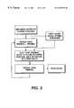
- FIG. 3shows one embodiment of the invention in a flow chart format
- FIG. 4is a representation of a full tone and a ⁇ fraction (1/16) ⁇ tone density pattern created by ink ejection onto a record medium.
- FIG. 5shows another embodiment of the invention in a flow chart format.
- the printer 2 shown in FIG. 1has a printhead 3 mounted on a carriage 4 connected to receive ink from a supply container 6 .
- the printhead 2contains a plurality of ink channels (not shown in FIG. 1) which carry ink from the supply container 6 to respective ink ejecting orifices or nozzles 42 (FIG. 2 ).
- the carriage 4reciprocates back and forth across the page as indicated by the arrow 4 A. Droplets of ink are expelled from selected ones of the printhead nozzles by firing of selected resistors 40 (FIG. 2) in the printhead as described below and are directed towards a recording medium 8 which can be a cut sheet of paper, a web of paper, or other material.
- the priming maintenance station 10includes a capping member 12 which is coupled to an ink trap 14 through a first line 16 .
- the ink trap 14is coupled to a suction pump 18 through a second line 20 .
- the suction pump 18applies a negative pressure or a vacuum to the capping member 12 through the lines 20 , 16 and also through the ink trap 14 .
- the ink trap 14traps any ink or other debris which is drawn by the capping member 12 during a priming or maintenance operation.
- the capping member 12When the carriage 4 is parked within the priming/maintenance station 10 , the capping member 12 is moved towards the printhead 3 until the priming element 22 , which is coupled to the capping member 12 , contacts the printhead 2 . Once in contact, the priming element 22 is sealed against the front face of the printhead 2 , thereby surrounding the ink ejecting nozzles.
- Controller 30controls the movement of carriage 4 , the firing of the resistors, the movement of the capping member 12 and operation of the suction pump 18 .
- Controller 32also contains a timer 32 for purposes described below.
- FIG. 2shows a partial side view of the maintenance station showing capping member 12 following movement into a coupling (capped) position with respect to printhead 3 .
- the member 12can be moved by a drive motor 25 controlled by signals from controller 30 .
- Initiation of capping motionis conventionally created by the printhead 3 activating a switch during movement into the maintenance station.
- printhead 3has a single row of 128 resistors 40 , each resistor with an associated channel 42 and nozzle 44 .
- the signal to start motor 25is accompanied by a signal generated internally of the controller which is sent to timer 32 activating a timing circuit.
- a timing algorithmcontrols the priming operation from this point.
- signals from timer 32 to controller 30causes the printhead to be primed by application of a partial tone firing controlled by controller 30 .
- a partial tone firingcontrolled by controller 30 .
- a ⁇ fraction (1/16) ⁇ tone firingis created in which every fifth resistor is fired during a first stroke time period.
- stroke periodselapse followed by a second stroke in which the second resistor in the row is fired followed by firing of every fifth resistor.
- Full tone primingmay be initiated also in the case where a print mode signal is received less than one hour after entering the capped position. Once the full tone priming is completed, a partial tone priming is implemented. In the absence of a print signal, the routine is continued.
- the result of the full tone/partial tone firing sequenceis that any contaminant buildup either in the channels or nozzles is removed by the full tone firing, and air bubbles are reduced by the partial tone firing. Further, if the printhead is returned to a print mode soon after the full tone firing, the partial tone firing will allow the printhead to begin operation at a cooler, less stressful state.
- FIG. 4is a representation of the full tone and partial tone firings when accomplished onto a recording medium rather than into the capping member.
- the printhead firing sequenceprogresses from a solid tone pattern at the left to a partial tone ( ⁇ fraction (1/16) ⁇ pattern) on the right. It will be apparent that the full tone firing produces a high frequency firing creating a high density ink output pattern.
- the partial tone patternforms a dot pattern which is effectively a low frequency firing creating a low density ink output pattern.
- the above description of the firing algorithm shown in FIG. 3assumed that the printhead was placed into the capping position following completion of a print mode.
- the printheadcan also be placed into the capping position following a partial, or soft, printer shutdown in which power is reduced to a standby status. Power is maintained, however, to perform the firing sequence shown in FIG. 3 .
- the inventionalso contemplates a complete power shutdown of a printer either purposefully or catastrophically. This may result in the printhead being stranded at a location outside the maintenance station. Referring to FIG. 5, a complete powering off of the printer is followed at some power of time by power restoration (printer powered on). Controller 30 initiates an algorithm which determines the current location of the printhead and, if not within the capping position, moves it there.
- a vacuumis applied to the printhead nozzles followed by full tone priming and a partial tone priming.
- the printheadremains capped, and the FIG. 2 routine commences. If a print signal is received, the printhead returns to a print mode of operation.
- the printheadis maintained in a condition to begin an optimum print operation (at a reduced temperature and with reduced bubbles in the ink reservoir) by providing, at least a full tone priming followed by a partial tone priming While a full tone and a ⁇ fraction (1/16) ⁇ tone firing has been specified, other tone firing ratios may be used consistent with the principles of the invention as long as the firing which creates the high density pattern accomplishes the task of removing most of the contaminant buildup and the firing which creates the low density pattern clears air bubbles and allows the printhead to cool down.
- the priming methodhas been disclosed in the context of a thermal ink jet printhead where the transducers are resistors, it will be appreciated that the method is applicable to other types of printheads such as piezoelectric printheads.
- the controllercontrols operation of the transducers associated with the piezoelectric transducers associated with the nozzle ejection.
- the printhead disclosed aboveis of the “side shooter” type where ink is ejected from the sides of a channel.
- the inventionis equally applicable to a roofshooter type of printhead.
Landscapes
- Ink Jet (AREA)
Abstract
Description
Claims (16)
Priority Applications (2)
| Application Number | Priority Date | Filing Date | Title |
|---|---|---|---|
| US09/098,313US6357852B1 (en) | 1998-06-16 | 1998-06-16 | Method and apparatus for restoring an ink jet printhead |
| BR9902267-2ABR9902267A (en) | 1998-06-16 | 1999-06-15 | Method and apparatus for restoring an inkjet printhead. |
Applications Claiming Priority (1)
| Application Number | Priority Date | Filing Date | Title |
|---|---|---|---|
| US09/098,313US6357852B1 (en) | 1998-06-16 | 1998-06-16 | Method and apparatus for restoring an ink jet printhead |
Publications (1)
| Publication Number | Publication Date |
|---|---|
| US6357852B1true US6357852B1 (en) | 2002-03-19 |
Family
ID=22268739
Family Applications (1)
| Application Number | Title | Priority Date | Filing Date |
|---|---|---|---|
| US09/098,313Expired - LifetimeUS6357852B1 (en) | 1998-06-16 | 1998-06-16 | Method and apparatus for restoring an ink jet printhead |
Country Status (2)
| Country | Link |
|---|---|
| US (1) | US6357852B1 (en) |
| BR (1) | BR9902267A (en) |
Cited By (7)
| Publication number | Priority date | Publication date | Assignee | Title |
|---|---|---|---|---|
| US20050062817A1 (en)* | 2003-09-18 | 2005-03-24 | Mike Steed | Managing contaminants in a fluid-delivery device |
| US20050062816A1 (en)* | 2003-09-18 | 2005-03-24 | Ozgur Yildirim | Managing bubbles in a fluid-delivery device |
| US20050264620A1 (en)* | 2004-05-28 | 2005-12-01 | Videojet Technologies Inc. | Autopurge printing system |
| US20060284925A1 (en)* | 2005-06-15 | 2006-12-21 | Lexmark International, Inc. | Bubble purging system and method |
| US7347529B2 (en) | 2003-08-26 | 2008-03-25 | Industrial Technology Research Institute | Compound inkjet print head printer |
| US20120127222A1 (en)* | 2010-11-22 | 2012-05-24 | Chambers Mark A | Inkjet printer maintenance system |
| US11020982B2 (en) | 2016-06-27 | 2021-06-01 | Hewlett-Packard Development Company, L.P. | Printhead recirculation |
Citations (14)
| Publication number | Priority date | Publication date | Assignee | Title |
|---|---|---|---|---|
| US4571599A (en) | 1984-12-03 | 1986-02-18 | Xerox Corporation | Ink cartridge for an ink jet printer |
| US4638337A (en) | 1985-08-02 | 1987-01-20 | Xerox Corporation | Thermal ink jet printhead |
| US4679059A (en) | 1983-07-20 | 1987-07-07 | Ing. C. Olivetti & C., S.P.A. | High speed ink jet printer with improved electrical connection to the nozzles |
| USRE32572E (en) | 1985-04-03 | 1988-01-05 | Xerox Corporation | Thermal ink jet printhead and process therefor |
| US4746938A (en) | 1985-07-11 | 1988-05-24 | Matsushita Electric Industrial Co. Ltd. | Ink jet recording apparatus with head washing device |
| US4849774A (en) | 1977-10-03 | 1989-07-18 | Canon Kabushiki Kaisha | Bubble jet recording apparatus which projects droplets of liquid through generation of bubbles in a liquid flow path by using heating means responsive to recording signals |
| US4853717A (en) | 1987-10-23 | 1989-08-01 | Hewlett-Packard Company | Service station for ink-jet printer |
| US4855764A (en) | 1986-02-25 | 1989-08-08 | Siemens Aktiengesellschaft | Apparatus for sealing and cleaning the ink discharge openings at an ink printing head |
| US4970527A (en) | 1988-12-02 | 1990-11-13 | Spectra-Physics, Incorporated | Priming method for inkjet printers |
| US5182580A (en)* | 1990-02-26 | 1993-01-26 | Canon Kabushiki Kaisha | Ink jet recording apparatus with abnormal state detection |
| US5353051A (en)* | 1990-02-02 | 1994-10-04 | Canon Kabushiki Kaisha | Recording apparatus having a plurality of recording elements divided into blocks |
| US5530462A (en)* | 1989-01-24 | 1996-06-25 | Canon Kabushiki Kaisha | Recovery technique for ink jet recording apparatus |
| US5805182A (en)* | 1995-03-04 | 1998-09-08 | Samsung Electronics Co., Ltd. | Method and apparatus for cleaning nozzles in an ink jet printer |
| US6024432A (en)* | 1996-10-21 | 2000-02-15 | Seiko Epson Corporation | Ink-jet recording apparatus |
- 1998
- 1998-06-16USUS09/098,313patent/US6357852B1/ennot_activeExpired - Lifetime
- 1999
- 1999-06-15BRBR9902267-2Apatent/BR9902267A/ennot_activeIP Right Cessation
Patent Citations (14)
| Publication number | Priority date | Publication date | Assignee | Title |
|---|---|---|---|---|
| US4849774A (en) | 1977-10-03 | 1989-07-18 | Canon Kabushiki Kaisha | Bubble jet recording apparatus which projects droplets of liquid through generation of bubbles in a liquid flow path by using heating means responsive to recording signals |
| US4679059A (en) | 1983-07-20 | 1987-07-07 | Ing. C. Olivetti & C., S.P.A. | High speed ink jet printer with improved electrical connection to the nozzles |
| US4571599A (en) | 1984-12-03 | 1986-02-18 | Xerox Corporation | Ink cartridge for an ink jet printer |
| USRE32572E (en) | 1985-04-03 | 1988-01-05 | Xerox Corporation | Thermal ink jet printhead and process therefor |
| US4746938A (en) | 1985-07-11 | 1988-05-24 | Matsushita Electric Industrial Co. Ltd. | Ink jet recording apparatus with head washing device |
| US4638337A (en) | 1985-08-02 | 1987-01-20 | Xerox Corporation | Thermal ink jet printhead |
| US4855764A (en) | 1986-02-25 | 1989-08-08 | Siemens Aktiengesellschaft | Apparatus for sealing and cleaning the ink discharge openings at an ink printing head |
| US4853717A (en) | 1987-10-23 | 1989-08-01 | Hewlett-Packard Company | Service station for ink-jet printer |
| US4970527A (en) | 1988-12-02 | 1990-11-13 | Spectra-Physics, Incorporated | Priming method for inkjet printers |
| US5530462A (en)* | 1989-01-24 | 1996-06-25 | Canon Kabushiki Kaisha | Recovery technique for ink jet recording apparatus |
| US5353051A (en)* | 1990-02-02 | 1994-10-04 | Canon Kabushiki Kaisha | Recording apparatus having a plurality of recording elements divided into blocks |
| US5182580A (en)* | 1990-02-26 | 1993-01-26 | Canon Kabushiki Kaisha | Ink jet recording apparatus with abnormal state detection |
| US5805182A (en)* | 1995-03-04 | 1998-09-08 | Samsung Electronics Co., Ltd. | Method and apparatus for cleaning nozzles in an ink jet printer |
| US6024432A (en)* | 1996-10-21 | 2000-02-15 | Seiko Epson Corporation | Ink-jet recording apparatus |
Cited By (12)
| Publication number | Priority date | Publication date | Assignee | Title |
|---|---|---|---|---|
| US7347529B2 (en) | 2003-08-26 | 2008-03-25 | Industrial Technology Research Institute | Compound inkjet print head printer |
| US20050062817A1 (en)* | 2003-09-18 | 2005-03-24 | Mike Steed | Managing contaminants in a fluid-delivery device |
| US20050062816A1 (en)* | 2003-09-18 | 2005-03-24 | Ozgur Yildirim | Managing bubbles in a fluid-delivery device |
| US7093930B2 (en) | 2003-09-18 | 2006-08-22 | Hewlett-Packard Development Company, L.P. | Managing bubbles in a fluid-delivery device |
| US7111932B2 (en) | 2003-09-18 | 2006-09-26 | Hewlett-Packard Development Company | Managing contaminants in a fluid-delivery device |
| US20050264620A1 (en)* | 2004-05-28 | 2005-12-01 | Videojet Technologies Inc. | Autopurge printing system |
| US7118189B2 (en) | 2004-05-28 | 2006-10-10 | Videojet Technologies Inc. | Autopurge printing system |
| US20060284925A1 (en)* | 2005-06-15 | 2006-12-21 | Lexmark International, Inc. | Bubble purging system and method |
| US7591549B2 (en) | 2005-06-15 | 2009-09-22 | Lexmark International, Inc. | Bubble purging system and method |
| US20120127222A1 (en)* | 2010-11-22 | 2012-05-24 | Chambers Mark A | Inkjet printer maintenance system |
| US8944545B2 (en)* | 2010-11-22 | 2015-02-03 | Funai Electric Co., Ltd | Imaging device including a printhead controlled to eject fluid |
| US11020982B2 (en) | 2016-06-27 | 2021-06-01 | Hewlett-Packard Development Company, L.P. | Printhead recirculation |
Also Published As
| Publication number | Publication date |
|---|---|
| BR9902267A (en) | 2000-02-22 |
Similar Documents
| Publication | Publication Date | Title |
|---|---|---|
| EP1270234B1 (en) | Ink jet recording apparatus and recovery method thereof | |
| US4668965A (en) | Method of purging impurities from a printing head | |
| US5530463A (en) | Integral seal for ink jet printheads | |
| US6033050A (en) | Liquid ejection printing apparatus with varying frequency preliminary ejection | |
| JPH0519468B2 (en) | ||
| JPH07205434A (en) | Fixed wiper blade assembly | |
| JPH0557913B2 (en) | ||
| US5138334A (en) | Pneumatic surface cleaning method and apparatus for ink jet printheads | |
| WO1997003835A1 (en) | Method and apparatus for ink jet recording | |
| JP3679865B2 (en) | Inkjet recording device | |
| JP3587111B2 (en) | Ink jet recording device | |
| US6357852B1 (en) | Method and apparatus for restoring an ink jet printhead | |
| US20020093547A1 (en) | Inkjet printhead with high nozzle to pressure activator ratio | |
| JP3671998B2 (en) | Inkjet recording device | |
| JPH11192723A (en) | Image forming apparatus | |
| US5483266A (en) | Ink jet recording apparatus with two storage modes | |
| JPH11334106A (en) | Inkjet method and apparatus | |
| JPH0592579A (en) | Inkjet recording device | |
| JPS63260451A (en) | Inkjet recording device and cleaning method for the device | |
| US5440330A (en) | Method and apparatus for kogation removal from a heater element of a thermal ink jet printer | |
| US6398337B1 (en) | Ink jet printhead scrubbing and priming apparatus and method | |
| JP2804613B2 (en) | Ink jet recording method and apparatus | |
| US5710581A (en) | Inkjet printhead having intermittent nozzle clearing | |
| US6450609B1 (en) | Methods for charging and priming fluid ejector heads | |
| JP2740228B2 (en) | Liquid jet recording apparatus and recovery method for liquid jet recording apparatus |
Legal Events
| Date | Code | Title | Description |
|---|---|---|---|
| AS | Assignment | Owner name:XEROX CORPORATION, CONNECTICUT Free format text:ASSIGNMENT OF ASSIGNORS INTEREST;ASSIGNORS:PREMNATH, KARAI P.;DABROWNY, STANLEY;KING, WILLIAM L.;REEL/FRAME:009258/0617 Effective date:19980612 | |
| STCF | Information on status: patent grant | Free format text:PATENTED CASE | |
| AS | Assignment | Owner name:BANK ONE, NA, AS ADMINISTRATIVE AGENT, ILLINOIS Free format text:SECURITY INTEREST;ASSIGNOR:XEROX CORPORATION;REEL/FRAME:013153/0001 Effective date:20020621 Owner name:BANK ONE, NA, AS ADMINISTRATIVE AGENT, ILLINOIS Free format text:SECURITY INTEREST;ASSIGNOR:XEROX CORPORATION;REEL/FRAME:013153/0001D Effective date:20020621 | |
| AS | Assignment | Owner name:JPMORGAN CHASE BANK, AS COLLATERAL AGENT, TEXAS Free format text:SECURITY AGREEMENT;ASSIGNOR:XEROX CORPORATION;REEL/FRAME:015134/0476 Effective date:20030625 Owner name:JPMORGAN CHASE BANK, AS COLLATERAL AGENT,TEXAS Free format text:SECURITY AGREEMENT;ASSIGNOR:XEROX CORPORATION;REEL/FRAME:015134/0476 Effective date:20030625 | |
| FEPP | Fee payment procedure | Free format text:PAYOR NUMBER ASSIGNED (ORIGINAL EVENT CODE: ASPN); ENTITY STATUS OF PATENT OWNER: LARGE ENTITY | |
| AS | Assignment | Owner name:SAMSUNG ELECTRONICS CO., LTD., KOREA, REPUBLIC OF Free format text:ASSIGNMENT OF ASSIGNORS INTEREST;ASSIGNOR:XEROX CORPORATION;REEL/FRAME:015687/0884 Effective date:20050113 | |
| AS | Assignment | Owner name:XEROX CORPORATION, CONNECTICUT Free format text:RELEASE OF PATENTS;ASSIGNOR:JP MORGAN CHASE BANK, N.A.;REEL/FRAME:016408/0016 Effective date:20050330 | |
| FPAY | Fee payment | Year of fee payment:4 | |
| FPAY | Fee payment | Year of fee payment:8 | |
| FEPP | Fee payment procedure | Free format text:PAYOR NUMBER ASSIGNED (ORIGINAL EVENT CODE: ASPN); ENTITY STATUS OF PATENT OWNER: LARGE ENTITY Free format text:PAYER NUMBER DE-ASSIGNED (ORIGINAL EVENT CODE: RMPN); ENTITY STATUS OF PATENT OWNER: LARGE ENTITY | |
| FPAY | Fee payment | Year of fee payment:12 | |
| AS | Assignment | Owner name:XEROX CORPORATION, NEW YORK Free format text:RELEASE OF SECURITY INTEREST;ASSIGNOR:BANK ONE, NA;REEL/FRAME:033255/0545 Effective date:20030625 | |
| AS | Assignment | Owner name:XEROX CORPORATION, NEW YORK Free format text:RELEASE BY SECURED PARTY;ASSIGNOR:JPMORGAN CHASE BANK, N.A.;REEL/FRAME:034500/0564 Effective date:20061204 | |
| AS | Assignment | Owner name:S-PRINTING SOLUTION CO., LTD., KOREA, REPUBLIC OF Free format text:ASSIGNMENT OF ASSIGNORS INTEREST;ASSIGNOR:SAMSUNG ELECTRONICS CO., LTD;REEL/FRAME:041852/0125 Effective date:20161104 | |
| AS | Assignment | Owner name:HP PRINTING KOREA CO., LTD., KOREA, REPUBLIC OF Free format text:CHANGE OF NAME;ASSIGNOR:S-PRINTING SOLUTION CO., LTD.;REEL/FRAME:047370/0405 Effective date:20180316 | |
| AS | Assignment | Owner name:HP PRINTING KOREA CO., LTD., KOREA, REPUBLIC OF Free format text:CORRECTIVE ASSIGNMENT TO CORRECT THE DOCUMENTATION EVIDENCING THE CHANGE OF NAME PREVIOUSLY RECORDED ON REEL 047370 FRAME 0405. ASSIGNOR(S) HEREBY CONFIRMS THE CHANGE OF NAME;ASSIGNOR:S-PRINTING SOLUTION CO., LTD.;REEL/FRAME:047769/0001 Effective date:20180316 | |
| AS | Assignment | Owner name:HP PRINTING KOREA CO., LTD., KOREA, REPUBLIC OF Free format text:CHANGE OF LEGAL ENTITY EFFECTIVE AUG. 31, 2018;ASSIGNOR:HP PRINTING KOREA CO., LTD.;REEL/FRAME:050938/0139 Effective date:20190611 | |
| AS | Assignment | Owner name:HEWLETT-PACKARD DEVELOPMENT COMPANY, L.P., TEXAS Free format text:CONFIRMATORY ASSIGNMENT EFFECTIVE NOVEMBER 1, 2018;ASSIGNOR:HP PRINTING KOREA CO., LTD.;REEL/FRAME:050747/0080 Effective date:20190826 | |
| AS | Assignment | Owner name:XEROX CORPORATION, CONNECTICUT Free format text:RELEASE BY SECURED PARTY;ASSIGNOR:JPMORGAN CHASE BANK, N.A. AS SUCCESSOR-IN-INTEREST ADMINISTRATIVE AGENT AND COLLATERAL AGENT TO JPMORGAN CHASE BANK;REEL/FRAME:066728/0193 Effective date:20220822 |