US6357709B1 - Bracket assembly with split clamp member - Google Patents
Bracket assembly with split clamp memberDownload PDFInfo
- Publication number
- US6357709B1 US6357709B1US09/338,910US33891099AUS6357709B1US 6357709 B1US6357709 B1US 6357709B1US 33891099 AUS33891099 AUS 33891099AUS 6357709 B1US6357709 B1US 6357709B1
- Authority
- US
- United States
- Prior art keywords
- bracket assembly
- tubular portion
- connector
- cable
- assembly
- Prior art date
- Legal status (The legal status is an assumption and is not a legal conclusion. Google has not performed a legal analysis and makes no representation as to the accuracy of the status listed.)
- Expired - Lifetime
Links
- 230000008878couplingEffects0.000claimsdescription25
- 238000010168coupling processMethods0.000claimsdescription25
- 238000005859coupling reactionMethods0.000claimsdescription25
- 230000013011matingEffects0.000claimsdescription13
- 238000004519manufacturing processMethods0.000abstractdescription6
- 229910000831SteelInorganic materials0.000abstractdescription5
- 239000010959steelSubstances0.000abstractdescription5
- 238000009434installationMethods0.000abstractdescription4
- 230000000712assemblyEffects0.000description3
- 238000000429assemblyMethods0.000description3
- 238000004026adhesive bondingMethods0.000description1
- 238000006073displacement reactionMethods0.000description1
- 210000005069earsAnatomy0.000description1
- 238000000034methodMethods0.000description1
- 238000003466weldingMethods0.000description1
Images
Classifications
- F—MECHANICAL ENGINEERING; LIGHTING; HEATING; WEAPONS; BLASTING
- F21—LIGHTING
- F21V—FUNCTIONAL FEATURES OR DETAILS OF LIGHTING DEVICES OR SYSTEMS THEREOF; STRUCTURAL COMBINATIONS OF LIGHTING DEVICES WITH OTHER ARTICLES, NOT OTHERWISE PROVIDED FOR
- F21V21/00—Supporting, suspending, or attaching arrangements for lighting devices; Hand grips
- F21V21/10—Pendants, arms, or standards; Fixing lighting devices to pendants, arms, or standards
- F21V21/116—Fixing lighting devices to arms or standards
- G—PHYSICS
- G09—EDUCATION; CRYPTOGRAPHY; DISPLAY; ADVERTISING; SEALS
- G09F—DISPLAYING; ADVERTISING; SIGNS; LABELS OR NAME-PLATES; SEALS
- G09F7/00—Signs, name or number plates, letters, numerals, or symbols; Panels or boards
- G09F7/18—Means for attaching signs, plates, panels, or boards to a supporting structure
- F—MECHANICAL ENGINEERING; LIGHTING; HEATING; WEAPONS; BLASTING
- F21—LIGHTING
- F21W—INDEXING SCHEME ASSOCIATED WITH SUBCLASSES F21K, F21L, F21S and F21V, RELATING TO USES OR APPLICATIONS OF LIGHTING DEVICES OR SYSTEMS
- F21W2111/00—Use or application of lighting devices or systems for signalling, marking or indicating, not provided for in codes F21W2102/00 – F21W2107/00
- F21W2111/02—Use or application of lighting devices or systems for signalling, marking or indicating, not provided for in codes F21W2102/00 – F21W2107/00 for roads, paths or the like
Definitions
- the present inventionrelates to brackets for mounting traffic control devices and other objects to mast arms and other support members.
- Traffic lights and other traffic control devicesare mounted on a variety of supports, including mast arms, of varying diameters and orientations.
- Mounting brackets for traffic control devicesshould be sturdy, adjustable and simple to install.
- One such bracketis the ASTRO-BRAC brand described in U.S. Pat. No. 4,659,046, which is incorporated herein by reference.
- the ASTRO-BRAC® bracket(Pelco Products, Inc. of Edmond, Okla. comprises a male tubular member telescopically received within a female tubular member and secured therein by a snap ring.
- the bracketis attached to the mast arm by an anchor plate and steel bands or cable.
- the bracketis attached to the traffic control device by a clamp plate and U-bolts. While the ASTRO-BRAC® bracket provides strength and versatility, there remains a need for improvements to reduce the cost of manufacturing, to simplify installation and to increase stability of the installed bracket assembly.
- the present inventionis directed to a bracket assembly for supporting a traffic control device on a support member.
- the bracket assemblycomprises a male member having a tubular portion and a connecting portion.
- the connecting portionis connectable to either the traffic control device or the support member.
- the male memberdefines a throughbore extending through the tubular portion and the connecting portion.
- the bracket assemblyfurther includes a female member having a tubular portion and a connecting portion.
- the connecting portionis connectable to the other one of the traffic control device or the support member.
- the female memberdefines a throughbore extending through the connecting portion and the tubular portion.
- the female memberis divided longitudinally to form a pair of mating halves connectable to each other.
- the tubular portions of the mating halvesare sized to clamp around the tubular portion of the male member.
- the bracket assembly of the present inventioncomprises a first member having a tubular portion defining a throughbore.
- Means, having a throughboreis included in the bracket assembly for removably and adjustably connecting the bracket assembly to the traffic control device.
- a second memberhaving a tubular portion defining a throughbore. The second member is divided longitudinally to form a pair of mating halves connectable to each other, and the tubular portions of the mating halves are sized to clamp around the tubular portion of the first member.
- means, having a throughborefor removably and adjustably connecting the bracket assembly to the support member. The throughbores of the tubular portions of the first and second members are aligned with the throughbores of the support member connecting means and the traffic control device connecting means.
- the present inventioncomprises a bracket assembly for supporting a traffic control device on a mast arm.
- the bracket assemblyincludes a male member comprising a tubular portion with a front end and rear end and defining a throughbore.
- a female memberis included, and it has a tubular portion with a rear end and also defines a throughbore.
- the female memberis divided longitudinally to form a pair of mating halves connectable to each other.
- the tubular portions of the mating halvesare sized to clamp around the tubular portion of the male member.
- the bracket assemblyfurther comprises a clamp plate having a throughbore, and a connector assembly for removably and adjustably connecting the clamp plate to the traffic control device.
- the bracket assemblyalso is provided with an anchor plate having a throughbore, and a connector assembly for removably and adjustably connecting the anchor plate to the mast arm.
- the throughbores of the male and female members, the clamp plate and the anchor plateall are coaxially aligned when assembled.
- the present inventionincludes a bracket assembly for supporting a traffic control device on a support member, wherein the bracket assembly comprises first and second members each having a coupling portion defining a wiring passageway therethrough.
- the coupling portion of the second memberis divided longitudinally to form at least two sections connectable to each other, wherein the at least two sections of the coupling portion are sized to clamp around the coupling portion of the first member.
- the bracket assemblyalso includes first and second connectors, each having a wiring passageway therethrough.
- the first connectorconnects the bracket assembly to the support member.
- the second connectorconnects the bracket assembly to the traffic control device.
- the wiring passageways of the coupling portions of the first and second memberscommunicate with the wiring passageways of the first and second connectors to form a continuous wiring path through the bracket assembly.
- the inventionis directed to a bracket assembly for supporting an object on a support member.
- the bracket assemblycomprises a first member having a coupling portion defining a passageway extending therethrough, and a second member having a coupling portion defining a passageway therethrough.
- the coupling portion of the second memberis divided longitudinally to form at least two sections connectable to each other, these two sections being sized to clamp around the coupling portion of the first member.
- a first connector, having a passageway therethrough,is included for connecting the bracket assembly to the support member.
- a second connector, having a passageway therethrough,is provided for connecting the bracket assembly to the object.
- the passageways of the coupling portions of the first and second memberscommunicate with the passageways of the first and second connectors to form a continuous passageway through the bracket assembly.
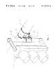
- FIG. 1is a right frontal perspective view of the bracket assembly of the present invention shown attached to a mast arm and supporting a three light traffic signal.
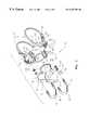
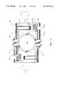
- FIG. 2is a right frontal perspective, partially exploded view of the bracket assembly shown in FIG 1 .
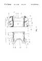
- FIG. 3is a side elevational, exploded view of the male and female members of the assembly.
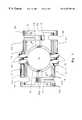
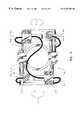
- FIG. 4is a front elevational view of the split clamp member of the bracket assembly with the bands and screw assemblies removed to illustrate the identical configuration of the two halves.
- FIG. 5is a front elevational view of the split clamp member of the bracket assembly showing attachment of the anchor plate by steel bands.
- FIG. 6is a front elevational view of the split clamp member showing attachment of the anchor plate by a cable.
- bracket assemblyconstructed in accordance with the present invention and designated generally by the reference numeral 10 .
- the bracket assembly 10is shown in FIG. 1 attached to a mast arm 12 and supporting a three light vertical traffic signal 14 .
- this bracket assemblycan be used to support a wide variety of traffic control devices and other objects, and can be attached to support members other than mast arms, both horizontal and vertical.
- traffic control devicerefers to any signal, sign or device supported by or over or near a roadway for affecting vehicular or pedestrian traffic, or both. This includes traffic signals and signs for controlling the direction and flow of automotive and railroad vehicles and pedestrian traffic, as well as warning devices, such as lights, signs and horns for all forms of vehicular and pedestrian traffic, such as railroad crossing signals.
- the bracket assembly 10comprises a first male member 16 and a second female member 18 .
- the male member 16comprises a coupling portion such as the tubular portion 20 with a front end 22 and a rear end 24 .
- the tubular portion 20defines a passageway therethrough for containing the wiring associated with the traffic control device, such as the throughbore 26 .
- the male memberfurther comprises a connecting portion for connecting the bracket assembly to either a support member, such as a mast arm, or to an object such a traffic control device or traffic signal 14 (FIG. 1 ).
- this connectionis removable or adjustable, and more preferably this connection is both removable and adjustable.
- a preferred connecting portiontakes the form of a clamp plate 30 for connecting the bracket assembly to the traffic signal 14 .
- the connecting portioncould take other forms.
- the connecting portioncould be configured to telescopically, slidably, hingedly, or threadedly engage the object or support member.
- the clamp plate 30is provided with an arcuate channel 32 transverse to the longitudinal axis of the throughbore 26 , and the throughbore extends through the clamp plate 30 . While in the preferred embodiment, the arcuate channel 32 is transverse to the throughbore 26 , the arcuate channel can be oriented other than transversely.
- the arcuate channel 32is shaped to receive the elongate member 34 of the traffic signal 14 (FIG. 1 ). However, the size and configuration of the clamp plate 30 will be modified depending on the size and shape of the member to which it is to be attached. On either side of the arcuate channel 32 , flanges 35 extend laterally.
- the flanges 35have at least one and preferably two bolt holes 36 which receive the ends of U-bolts 38 , or other connector assembly for removably and adjustably connecting the clamp plate 30 to the traffic signal 14 .
- the preferred U-bolt 38has a V-shaped back portion 40 , as this enhances the fit of the bolt on different diameter structures.
- connecting portioncan vary depending on the means by which it is affixed to the traffic control device or support member.
- the clamp platecould be attached by steel straps or cables instead of bolts, or it could be affixed directly by bolts, welding, gluing or the like.
- the connecting portionneed not be plate-like in configuration, but could take other forms.
- the connecting portioncould be configured to telescopically, slidably, hingedly, or threadedly engage the object or support member.
- the front end 22 of the tubular portion 20 of the male member 16is provided with an annular flange 44 , for a purpose yet to be described.
- the female member 18 of the bracket assembly 10comprises a coupling portion such as the tubular portion 45 that defines a wiring passageway therethrough, such as the throughbore 46 .
- the tubular portionhas a front end 48 and a rear end 50 .
- An annular shoulder 51(FIG. 3) is formed inside the tubular portion at the rear end 50 , for a purpose that will become apparent.
- the female member 18is divided longitudinally to form a pair of mating halves connectable to each other.
- the halves 45 A and 45 Btogether define the tubular portion 45 and the connecting portion, described hereafter.
- the tubular portions 45 A and 45 Bare sized to clamp around the tubular portion 20 of the male member 16 .
- male and female membershave been described herein as being tubular and as having throughbores. These terms should not be construed as limiting the members to any specific shape such as round. Rather, the male and female members could have other shapes such as square, hexagonal, octagonal and the like, so long as the male member is receivable in the female member.
- the halves 45 A and 45 Bmay be provided with flanges 60 with aligned bolt holes 62 therein for receiving at least one and preferably two bolts 64 .
- the throughbores 26 and 46 of the male and female members 16 and 18 and the throughbores of their respective connecting portionsare all coaxially aligned, which is preferable. It will be appreciated, though, that depending on the shape of the bracket the wiring passageways need not be linearly arranged, so long as the wiring passageways of the coupling portions and connecting portions form a continuous wiring path through the bracket assembly.
- the bracket assembly 10comprises an axial stop for retaining the tubular portion 20 of the male member 16 inside the tubular portion 45 of the female member 18 when the tubular portion of the female member is clamped around the tubular portion of the male member.
- annular flange 44 on the front end 22 of the male member tubular portion 20 and the annular shoulder 51 on the rear end 50 of the female member tubular portion 45serve this purpose. More specifically, and as best seen in FIG. 3, the annular flange 44 will engage the annular shoulder 51 when the bracket assembly is assembled, so that displacement of the male member 16 from the female member 18 is prevented. It may also be desirable to form ears 66 on the male member tubular portion 20 to limit axial movement of the female member 18 on the end opposite the flange 44 and shoulder 51 .
- the cooperating flange and shoulder integrally formed on the inside of the bracket assemblyis a preferred type of axial stop as it simplifies both manufacture of the assembly and installation by the customer.
- a circumferential groovemay be substituted for the flange on the front end of the male tubular portion.
- a snap ringsized to fit in the groove and to engage the annular shoulder when the female tubular member is clamped around the tubular portion of the male member.
- the snap ringsecures the axial position of the male and female members.
- one or more stop screwsmay be employed. This is accomplished by forming screw holes through the front end of the male tubular member for receiving stop screws. In this way, the expanded heads of the stop screws engage the annular shoulder of the rear end of the female tubular member to prevent axial dislodgement.
- This stop screw arrangementis described in detail in U.S. Pat. No. 5,340,069, entitled “Bracket for Traffic Control Device,” issued Aug. 23, 1994, the content of which is incorporated herein by reference.
- the female member 18 of the bracket assembly 10further comprises a connecting portion that is divided longitudinally into halves corresponding to the halves 45 A and 45 B of the tubular portion 45 .
- the connection portionis connectable to either a support member, such as the mast arm 12 , or a traffic control device, such as the traffic signal 14 (See FIG. 1 ).
- this connectionis removable or adjustable, and more preferably this connection is both removable and adjustable.
- the connecting portion of the female membershould be adapted to connect to the traffic control device if the male member connects to the mast arm, and to the mast arm if the male member connects to the traffic control device.
- the connecting portion of the female member 18preferably takes the form of an anchor plate 70 formed by the two halves 70 A and 70 B which are connectable to the mast arm 12 (See FIG. 1 ).
- the anchor plates 70 A and 70 Bare provided with a channel 72 (FIG. 3) sized to receive the mast arm 12 (or other structure).
- the anchor plate 70can be replaced with any other sort of connecting portion.
- the connecting portioncould be configured to telescopically, slidably, hingedly, or threadedly engage the object or support member.
- the preferred anchor plate 70 in this inventionis adapted for use with elongate connectors, such as flexible steel bands 74 .
- the anchor plate 70may be adapted for use with a cable type connector, most likely a single length of cable 75 , as shown in FIG. 6 .
- the anchor plate 70is adapted for connection to a band and alternately to a cable. This allows manufacture of only one style anchor plate, which then can be assembled for shipment with either a cable mounting assembly or a band mounting assembly, depending on the customer's request.
- the two halves of the split female member 18preferably are identically formed. Because the halves 70 A and 70 B of the anchor plate 70 are identically formed, only the half 70 B will be described in detail.
- the anchor plate 70 Bis characterized by at least a first track 76 sized to receive and align a portion of the band 74 , which is disposable in the track.
- the track 76preferably begins at a blind end 78 near the middle of the anchor plate 70 B and extends over the top edge 80 thereof.
- One end of the band 74is looped and attached at the blind end 78 of the track 76 with a pin 82 (FIG. 2 ).
- the other end of the band 74is left free until the bracket assembly is installed.
- the free endis attached to the anchor plate 70 B by means of a connector attachment/adjustment assembly, such as the screw assembly 84 (FIGS. 2 and 5 ).
- the preferred screw assembly 84includes a nut 86 which pulls the threaded end of the screw 87 up through through an aperture, such as the notch or pawl 88 in the bottom edge 90 of the anchor plate 70 B.
- the free end of the band 74is attached to the lower end of the screw assembly 84 by some means such as a band buckle 92 , for example.
- the nut 86is threaded further, pulling the screw 87 up through the pawl 88 until the band 84 is tightened sufficiently around the mast arm 12 (FIG. 1 ).
- the band on the other side of the anchor plate 70 Ais similarly assembled and tightened.
- the anchor plates 70 A and 70 Balternately can be secured to the mast arm 12 (FIG. 1) by means of a cable using a screw assembly similar to that described for use with the bands 74 .
- the anchor plate 70 A(and, of course, the anchor plate 70 B, although it will not be described in detail) preferably is modified to include a second track comprising a small, radiused groove 94 shaped to receive and align a portion of the cable 75 , which is disposable therein.
- a screw assembly 100is provided for each end 96 and 98 of the cable 75 .
- the ends 96 and 98 of the cable 75are attached to the screw assembly 100 in some suitable manner (not shown). Then the screws are placed in the pawl 88 and the nuts are tightened to secure the anchor plate 70 on the mast arm 12 in a manner similar to that described above.
- the elongate connectoris a cable, such as the cable 75
- Screw holes 104can be provided in the anchor plate 70 A for connecting the plates and screws 102 .
- the anchor plates 70 A and 70 Bcan be provided with a pawl 88 sized to engage either the screw assembly 84 with for a band mount, or the screw assembly 100 for a cable mount.
- the cable-shaped groove 94can be aligned longitudinally within the track 76 .
- the halves of the anchor plateare formed with a first track for a first type of elongate connector, such a flat band, and a second track for a second type of connector having a shape different from the shape of the first type of elongate connector, such as a cable.
- the anchor platecan be provided with pinholes for connecting the ends of the bands at the blind end of each band track, as well as screw holes for the plates used to secure the cable in the second tracks.
- the cable and the bandsare attachable by means screw assemblies having the same size screws, a single pawl can be provided in the anchor plate for use with either screw assembly.
Landscapes
- Engineering & Computer Science (AREA)
- General Engineering & Computer Science (AREA)
- Physics & Mathematics (AREA)
- General Physics & Mathematics (AREA)
- Theoretical Computer Science (AREA)
- Clamps And Clips (AREA)
Abstract
Description
The present invention relates to brackets for mounting traffic control devices and other objects to mast arms and other support members.
Traffic lights and other traffic control devices are mounted on a variety of supports, including mast arms, of varying diameters and orientations. Mounting brackets for traffic control devices should be sturdy, adjustable and simple to install. One such bracket is the ASTRO-BRAC brand described in U.S. Pat. No. 4,659,046, which is incorporated herein by reference. The ASTRO-BRAC® bracket (Pelco Products, Inc. of Edmond, Okla. comprises a male tubular member telescopically received within a female tubular member and secured therein by a snap ring. The bracket is attached to the mast arm by an anchor plate and steel bands or cable. The bracket is attached to the traffic control device by a clamp plate and U-bolts. While the ASTRO-BRAC® bracket provides strength and versatility, there remains a need for improvements to reduce the cost of manufacturing, to simplify installation and to increase stability of the installed bracket assembly.
The present invention is directed to a bracket assembly for supporting a traffic control device on a support member. The bracket assembly comprises a male member having a tubular portion and a connecting portion. The connecting portion is connectable to either the traffic control device or the support member. The male member defines a throughbore extending through the tubular portion and the connecting portion. The bracket assembly further includes a female member having a tubular portion and a connecting portion. The connecting portion is connectable to the other one of the traffic control device or the support member. The female member defines a throughbore extending through the connecting portion and the tubular portion. Further, the female member is divided longitudinally to form a pair of mating halves connectable to each other. The tubular portions of the mating halves are sized to clamp around the tubular portion of the male member.
In another aspect, the bracket assembly of the present invention comprises a first member having a tubular portion defining a throughbore. Means, having a throughbore, is included in the bracket assembly for removably and adjustably connecting the bracket assembly to the traffic control device. Also included is a second member having a tubular portion defining a throughbore. The second member is divided longitudinally to form a pair of mating halves connectable to each other, and the tubular portions of the mating halves are sized to clamp around the tubular portion of the first member. Also included is means, having a throughbore, for removably and adjustably connecting the bracket assembly to the support member. The throughbores of the tubular portions of the first and second members are aligned with the throughbores of the support member connecting means and the traffic control device connecting means.
In yet another aspect, the present invention comprises a bracket assembly for supporting a traffic control device on a mast arm. The bracket assembly includes a male member comprising a tubular portion with a front end and rear end and defining a throughbore. A female member is included, and it has a tubular portion with a rear end and also defines a throughbore. The female member is divided longitudinally to form a pair of mating halves connectable to each other. The tubular portions of the mating halves are sized to clamp around the tubular portion of the male member. The bracket assembly further comprises a clamp plate having a throughbore, and a connector assembly for removably and adjustably connecting the clamp plate to the traffic control device. The bracket assembly also is provided with an anchor plate having a throughbore, and a connector assembly for removably and adjustably connecting the anchor plate to the mast arm. The throughbores of the male and female members, the clamp plate and the anchor plate all are coaxially aligned when assembled.
Still further, the present invention includes a bracket assembly for supporting a traffic control device on a support member, wherein the bracket assembly comprises first and second members each having a coupling portion defining a wiring passageway therethrough. The coupling portion of the second member is divided longitudinally to form at least two sections connectable to each other, wherein the at least two sections of the coupling portion are sized to clamp around the coupling portion of the first member. The bracket assembly also includes first and second connectors, each having a wiring passageway therethrough. The first connector connects the bracket assembly to the support member. The second connector connects the bracket assembly to the traffic control device. The wiring passageways of the coupling portions of the first and second members communicate with the wiring passageways of the first and second connectors to form a continuous wiring path through the bracket assembly.
In yet another aspect, the invention is directed to a bracket assembly for supporting an object on a support member. The bracket assembly comprises a first member having a coupling portion defining a passageway extending therethrough, and a second member having a coupling portion defining a passageway therethrough. The coupling portion of the second member is divided longitudinally to form at least two sections connectable to each other, these two sections being sized to clamp around the coupling portion of the first member. A first connector, having a passageway therethrough, is included for connecting the bracket assembly to the support member. A second connector, having a passageway therethrough, is provided for connecting the bracket assembly to the object. The passageways of the coupling portions of the first and second members communicate with the passageways of the first and second connectors to form a continuous passageway through the bracket assembly.
FIG. 1 is a right frontal perspective view of the bracket assembly of the present invention shown attached to a mast arm and supporting a three light traffic signal.
FIG. 2 is a right frontal perspective, partially exploded view of the bracket assembly shown in FIG1.
FIG. 3 is a side elevational, exploded view of the male and female members of the assembly.
FIG. 4 is a front elevational view of the split clamp member of the bracket assembly with the bands and screw assemblies removed to illustrate the identical configuration of the two halves.
FIG. 5 is a front elevational view of the split clamp member of the bracket assembly showing attachment of the anchor plate by steel bands.
FIG. 6 is a front elevational view of the split clamp member showing attachment of the anchor plate by a cable.
Turning now to the drawings in general and to FIG. 1 in particular, there is shown therein a bracket assembly constructed in accordance with the present invention and designated generally by thereference numeral 10. Thebracket assembly 10 is shown in FIG. 1 attached to amast arm 12 and supporting a three lightvertical traffic signal 14. However, this bracket assembly can be used to support a wide variety of traffic control devices and other objects, and can be attached to support members other than mast arms, both horizontal and vertical. As used herein, “traffic control device” refers to any signal, sign or device supported by or over or near a roadway for affecting vehicular or pedestrian traffic, or both. This includes traffic signals and signs for controlling the direction and flow of automotive and railroad vehicles and pedestrian traffic, as well as warning devices, such as lights, signs and horns for all forms of vehicular and pedestrian traffic, such as railroad crossing signals.
Referring now also to FIGS. 2 and 3, thebracket assembly 10 comprises afirst male member 16 and a secondfemale member 18. Themale member 16 comprises a coupling portion such as thetubular portion 20 with afront end 22 and arear end 24. Thetubular portion 20 defines a passageway therethrough for containing the wiring associated with the traffic control device, such as thethroughbore 26. The male member further comprises a connecting portion for connecting the bracket assembly to either a support member, such as a mast arm, or to an object such a traffic control device or traffic signal14 (FIG.1). Preferably, this connection is removable or adjustable, and more preferably this connection is both removable and adjustable. A preferred connecting portion takes the form of aclamp plate 30 for connecting the bracket assembly to thetraffic signal 14. However the connecting portion could take other forms. For example, the connecting portion could be configured to telescopically, slidably, hingedly, or threadedly engage the object or support member.
As best seen in FIGS. 2 and 3, theclamp plate 30 is provided with anarcuate channel 32 transverse to the longitudinal axis of thethroughbore 26, and the throughbore extends through theclamp plate 30. While in the preferred embodiment, thearcuate channel 32 is transverse to thethroughbore 26, the arcuate channel can be oriented other than transversely. Thearcuate channel 32 is shaped to receive theelongate member 34 of the traffic signal14 (FIG.1). However, the size and configuration of theclamp plate 30 will be modified depending on the size and shape of the member to which it is to be attached. On either side of thearcuate channel 32,flanges 35 extend laterally. Theflanges 35 have at least one and preferably twobolt holes 36 which receive the ends ofU-bolts 38, or other connector assembly for removably and adjustably connecting theclamp plate 30 to thetraffic signal 14. As shown in the drawings, the preferredU-bolt 38 has a V-shapedback portion 40, as this enhances the fit of the bolt on different diameter structures. Thus, by means of theclamp plate 30 and the cooperating U-bolts38, thebracket assembly 10 can be removably and adjustably connected to thetraffic signal 14.
Now it will be understood that while a clamp plate and bolts have been used in the preferred embodiment of this invention, other connecting portions and connecting assemblies may be substituted for these. For example, the configuration of the connecting portion can vary depending on the means by which it is affixed to the traffic control device or support member. The clamp plate could be attached by steel straps or cables instead of bolts, or it could be affixed directly by bolts, welding, gluing or the like. Similarly, the connecting portion need not be plate-like in configuration, but could take other forms. For example, the connecting portion could be configured to telescopically, slidably, hingedly, or threadedly engage the object or support member.
Referring still to FIGS. 2 and 3, thefront end 22 of thetubular portion 20 of themale member 16 is provided with anannular flange 44, for a purpose yet to be described.
Thefemale member 18 of thebracket assembly 10 comprises a coupling portion such as thetubular portion 45 that defines a wiring passageway therethrough, such as thethroughbore 46. The tubular portion has afront end 48 and arear end 50. An annular shoulder51 (FIG. 3) is formed inside the tubular portion at therear end 50, for a purpose that will become apparent.
Thefemale member 18 is divided longitudinally to form a pair of mating halves connectable to each other. Thus, thehalves tubular portion 45 and the connecting portion, described hereafter. Thetubular portions tubular portion 20 of themale member 16.
The male and female members have been described herein as being tubular and as having throughbores. These terms should not be construed as limiting the members to any specific shape such as round. Rather, the male and female members could have other shapes such as square, hexagonal, octagonal and the like, so long as the male member is receivable in the female member.
Neither is it essential that the wiring passageways be axially aligned or transversely centered. Rather, any passageway that extends end to end and will house the wiring for the traffic devices involved will suffice.
To connect thehalves flanges 60 with aligned bolt holes62 therein for receiving at least one and preferably twobolts 64. In this way, thethroughbores female members
In the preferred embodiment, thebracket assembly 10 comprises an axial stop for retaining thetubular portion 20 of themale member 16 inside thetubular portion 45 of thefemale member 18 when the tubular portion of the female member is clamped around the tubular portion of the male member. Now it will be appreciated that the previously describedannular flange 44 on thefront end 22 of the malemember tubular portion 20 and theannular shoulder 51 on therear end 50 of the femalemember tubular portion 45 serve this purpose. More specifically, and as best seen in FIG. 3, theannular flange 44 will engage theannular shoulder 51 when the bracket assembly is assembled, so that displacement of themale member 16 from thefemale member 18 is prevented. It may also be desirable to formears 66 on the malemember tubular portion 20 to limit axial movement of thefemale member 18 on the end opposite theflange 44 andshoulder 51.
The cooperating flange and shoulder integrally formed on the inside of the bracket assembly is a preferred type of axial stop as it simplifies both manufacture of the assembly and installation by the customer. Nevertheless, there exist various other ways of securing the male member axially relative to the female member when the female member clamped around the male member. For example, a circumferential groove may be substituted for the flange on the front end of the male tubular portion. In this embodiment of the bracket assembly, then, there is included a snap ring sized to fit in the groove and to engage the annular shoulder when the female tubular member is clamped around the tubular portion of the male member. Thus, the snap ring secures the axial position of the male and female members. This arrangement is described in detail in my earlier patent, U.S. Pat. No. 4,659,046, entitled “Traffic Control Device Mast Arm Bracket,” issued Apr. 21, 1987, the content of which is incorporated herein by reference.
Still further, one or more stop screws may be employed. This is accomplished by forming screw holes through the front end of the male tubular member for receiving stop screws. In this way, the expanded heads of the stop screws engage the annular shoulder of the rear end of the female tubular member to prevent axial dislodgement. This stop screw arrangement is described in detail in U.S. Pat. No. 5,340,069, entitled “Bracket for Traffic Control Device,” issued Aug. 23, 1994, the content of which is incorporated herein by reference.
Thefemale member 18 of thebracket assembly 10 further comprises a connecting portion that is divided longitudinally into halves corresponding to thehalves tubular portion 45. The connection portion is connectable to either a support member, such as themast arm 12, or a traffic control device, such as the traffic signal14 (See FIG.1). Preferably, this connection is removable or adjustable, and more preferably this connection is both removable and adjustable. It will be apparent that the connecting portion of the female member should be adapted to connect to the traffic control device if the male member connects to the mast arm, and to the mast arm if the male member connects to the traffic control device.
As illustrated in FIG. 2, and also in FIGS. 4,5 and6, the connecting portion of thefemale member 18 preferably takes the form of ananchor plate 70 formed by the twohalves anchor plates clamp plate 30, theanchor plate 70 can be replaced with any other sort of connecting portion. For example, the connecting portion could be configured to telescopically, slidably, hingedly, or threadedly engage the object or support member.
Turning briefly to FIGS. 1 and 5, thepreferred anchor plate 70 in this invention is adapted for use with elongate connectors, such asflexible steel bands 74. Alternately, theanchor plate 70 may be adapted for use with a cable type connector, most likely a single length ofcable 75, as shown in FIG.6. Even more preferably, theanchor plate 70 is adapted for connection to a band and alternately to a cable. This allows manufacture of only one style anchor plate, which then can be assembled for shipment with either a cable mounting assembly or a band mounting assembly, depending on the customer's request.
As best seen in FIGS. 4 and 5, the two halves of the splitfemale member 18 preferably are identically formed. Because thehalves anchor plate 70 are identically formed, only the half70B will be described in detail.
Theanchor plate 70B is characterized by at least afirst track 76 sized to receive and align a portion of theband 74, which is disposable in the track. Thetrack 76 preferably begins at ablind end 78 near the middle of theanchor plate 70B and extends over thetop edge 80 thereof. One end of theband 74 is looped and attached at theblind end 78 of thetrack 76 with a pin82 (FIG.2). The other end of theband 74 is left free until the bracket assembly is installed. At the time of installation, the free end is attached to theanchor plate 70B by means of a connector attachment/adjustment assembly, such as the screw assembly84 (FIGS.2 and5).
Referring still to FIGS. 2 and 5, thepreferred screw assembly 84 includes anut 86 which pulls the threaded end of thescrew 87 up through through an aperture, such as the notch orpawl 88 in thebottom edge 90 of theanchor plate 70B. The free end of theband 74 is attached to the lower end of thescrew assembly 84 by some means such as aband buckle 92, for example. Then, thenut 86 is threaded further, pulling thescrew 87 up through thepawl 88 until theband 84 is tightened sufficiently around the mast arm12 (FIG.1). The band on the other side of theanchor plate 70A is similarly assembled and tightened.
Now a particularly advantageous feature of this embodiment of the invention will be appreciated. Because the twohalves anchor plate 70B, while it is being tightened on themast arm 12, is in a direction opposite to the tension or torque of theanchor plate 70A, while it is being tightened. The directions of tension are illustrated by the arrows “T” in FIG.5. This provides a sturdy and durable connection.
As illustrated in FIG. 6, to which attention now is directed, theanchor plates bands 74. Returning to FIG. 4, theanchor plate 70A (and, of course, theanchor plate 70B, although it will not be described in detail) preferably is modified to include a second track comprising a small,radiused groove 94 shaped to receive and align a portion of thecable 75, which is disposable therein.
While it is not essential to the invention, it is most desirable to utilize a cable which is long enough to have oneend 96 attached to one half of theanchor plate 70A and the other end98 attached to the other half of theanchor plate 70B. In this arrangement, ascrew assembly 100 is provided for eachend 96 and98 of thecable 75. The ends96 and98 of thecable 75 are attached to thescrew assembly 100 in some suitable manner (not shown). Then the screws are placed in thepawl 88 and the nuts are tightened to secure theanchor plate 70 on themast arm 12 in a manner similar to that described above.
When the elongate connector is a cable, such as thecable 75, it is advantageous to include in the assembly a set of plates and screws, designated generally by the numeral102 for securing the cable in thegroove 94. Screw holes104 can be provided in theanchor plate 70A for connecting the plates and screws102. Thus, when thecable 75 is secured, the tension exerted on oneend 96 of the cable is opposite to the tension on the other end98, as illustrated by the arrows “T” in FIG.6.
Returning once again to FIG. 4, it will now be apparent that theanchor plates pawl 88 sized to engage either thescrew assembly 84 with for a band mount, or thescrew assembly 100 for a cable mount. To do this, the cable-shapedgroove 94 can be aligned longitudinally within thetrack 76.
Thus, for efficient production of thebracket assembly 10, the halves of the anchor plate are formed with a first track for a first type of elongate connector, such a flat band, and a second track for a second type of connector having a shape different from the shape of the first type of elongate connector, such as a cable. The anchor plate can be provided with pinholes for connecting the ends of the bands at the blind end of each band track, as well as screw holes for the plates used to secure the cable in the second tracks. Where, as described here, the cable and the bands are attachable by means screw assemblies having the same size screws, a single pawl can be provided in the anchor plate for use with either screw assembly. Thus, a single mold can be used and all anchor plate halves can be machined identically to produce split clamp (female) members with anchor plates attachable alternately by either bands or cables. This not only reduces the cost of manufacturing, but simplifies parts identification and inventory management as well. When a customer order is received, the two identical female members are combined with a male member and the requested type of mast arm connector assembly.
Changes may be made in the combination and arrangement of the various parts, elements steps and procedures described herein without departing from the spirit and scope of the invention as defined in the following claims.
Claims (65)
1. A bracket assembly for supporting a traffic control device on a support member, the bracket assembly comprising:
a male member having a tubular portion and a connecting portion, wherein the connecting portion is connectable to one of the traffic control device and the support member, and wherein the male member defines a throughbore extending through the tubular portion and the connecting portion; and
a female member having a tubular portion and a connecting portion, wherein the connecting portion is connectable to the other one of the traffic control device and the support member, wherein the female member defines a throughbore extending through the connecting portion and the tubular portion, wherein the female member is divided longitudinally to form a pair of mating separate halves connectable to each other, and wherein the tubular portions of the mating halves are sized to clamp around the tubular portion of the male member.
2. The bracket assembly ofclaim 1 wherein the halves of the female member are provided with flanges having aligned bolt holes therein, and wherein the bracket assembly includes at least one bolt receivable in the bolt holes.
3. The bracket assembly ofclaim 2 wherein the connecting portion connectable to the traffic control device has an arcuate channel transverse to the longitudinal axis of the throughbore, wherein the traffic control device connecting portion further has flanges extending lateral to the arcuate channel, wherein each of the flanges has at least one bolt hole, and wherein the bracket assembly further comprises at least one U-bolt receivable in the bolt holes in the flanges of the traffic control device connecting portion.
4. The bracket assembly ofclaim 3 wherein the curved portion of the U-bolt is V-shaped.
5. The bracket assembly ofclaim 1 wherein the support member connecting portion has a channel sized to receive the support member.
6. The bracket assembly ofclaim 5 wherein the support member connecting portion comprises an anchor plate that defines the channel.
7. The bracket assembly ofclaim 6 further comprising at least one band attachable to the anchor plate.
8. The bracket assembly ofclaim 6 further comprising at least one cable attachable to the anchor plate.
9. The bracket assembly ofclaim 6 wherein the anchor plate is adapted for connection to a band and alternately to a cable.
10. The bracket assembly ofclaim 1 comprising an axial stop for retaining the tubular portion of the male member inside the tubular portion of the female member when the tubular portion of the female member is clamped around the tubular portion of the male member.
11. The bracket assembly ofclaim 10 wherein the tubular portion of the female member has a rear end, wherein the rear end of the tubular portion is provided with an annular shoulder, wherein the tubular portion of the male member has a front end, and wherein the axial stop comprises an annular flange on the front end shaped to engage the annular shoulder when the tubular portion of the female member is clamped around the tubular portion of the male member.
12. The bracket assembly ofclaim 10 wherein the tubular portion of the female member has a rear end, wherein the rear end of the tubular portion is provided with an annular shoulder, wherein the tubular portion of the male member has a front end, wherein the front end of the male member tubular portion has at least one screw hole, and wherein the axial stop comprises at least one screw in the screw hole long enough to engage the annular shoulder when the tubular portion of the female member is clamped around the tubular portion of the male member.
13. The bracket assembly ofclaim 10 wherein the tubular portion of the female member has a rear end, wherein the rear end of the tubular portion is provided with an annular shoulder, wherein the tubular portion of the male member has a front end, wherein the front end of the female member tubular portion has a circumferential groove, and wherein the axial stop comprises a snap ring sized to fit in the groove and to engage the annular shoulder when the tubular portion of the female member is clamped around the tubular portion of the male member.
14. The bracket assembly ofclaim 1 wherein the halves of the split female member are identically formed.
15. The bracket assembly ofclaim 14 wherein the connector portion of each half comprises a plate and wherein the plate is characterized by:
at least a first track sized to receive and align a portion of at least a first type of elongate connector; and
an aperture sized to receive a connector attachment/adjustment assembly.
16. The bracket assembly ofclaim 15 further comprising a first type of elongate connector and a connector attachment/adjustment assembly.
17. The bracket assembly ofclaim 16 wherein the first type of elongate connector is a band, wherein one end of the band is attachable to the plate, wherein a portion of the band is disposable in the first track, wherein the connector attachment/adjustment assembly comprises a screw receivable in the aperture whereby the band can be tightened around the support member, whereby in the assembled bracket assembly tension on one band is in a direction opposite to the tension on the other band.
18. The bracket assembly ofclaim 16 wherein the first type of elongate connector is a cable, wherein a portion of the cable is disposable in the first track, wherein the connector attachment/adjustment assembly comprises a screw receivable in the aperture whereby the cable can be tightened around the support member, and whereby in the assembled bracket assembly tension on the cable on one half of the female member is in a direction opposite to the tension on the other half.
19. The bracket assembly ofclaim 18 wherein the cable is long enough to have one end attached to the screw in the aperture of each plate of the two halves of the female member, whereby in the assembled bracket assembly tension on one end of the cable is in a direction opposite to the tension on the other end of the cable, and wherein the bracket assembly further comprises means for securing a portion of the cable in the first track on each plate.
20. The bracket assembly ofclaim 15 wherein the plate is further characterized by a second track sized to receive and align a second type of elongate connector having a shape different from the shape of the first type of elongate connector.
21. The bracket assembly ofclaim 20 wherein the first track is sized to receive and align a band type connector and wherein the second track is sized to receive a cable type connector.
22. A bracket assembly for supporting a traffic control device on a support member, the bracket assembly comprising:
a first member having a tubular portion defining a throughbore;
means, having a throughbore, for removably and adjustably connecting the bracket assembly to the traffic control device;
a second member having a tubular portion defining a throughbore, and wherein the second member is divided longitudinally to form a pair of mating separate halves connectable to each other, and wherein the tubular portions of the mating halves are sized to clamp around the tubular portion of the first member;
means, having a throughbore, for removably and adjustably connecting the bracket assembly to the support member; and
wherein the throughbores of the tubular portions of the first and second members are aligned with the throughbores of the support member connecting means and the traffic control device connecting means.
23. The bracket assembly ofclaim 22 wherein the halves of the second member are provided with flanges having aligned bolt holes therein, and wherein the assembly includes at least one bolt receivable in the bolt holes.
24. The bracket assembly ofclaim 23 wherein the traffic control device connecting means comprises an arcuate channel transverse to the longitudinal axis of the throughbores and flanges extending lateral to the arcuate channel, wherein each of the flanges has at least one bolt hole, and wherein the traffic control device connecting means further comprises at least one U-bolt receivable in the bolt holes in the flanges.
25. The bracket assembly ofclaim 24 wherein the curved portion of the U-bolt is V-shaped.
26. The bracket assembly ofclaim 22 wherein the support member connecting means comprises a channel sized to receive the support member.
27. The bracket assembly ofclaim 26 wherein the support member connecting means comprises an anchor plate that defines the channel.
28. The bracket assembly ofclaim 27 wherein the support member connecting means further comprises at least one band attachable to the anchor plate.
29. The bracket assembly ofclaim 27 wherein the support member connecting means further comprises at least one cable attachable to the anchor plate.
30. The bracket assembly ofclaim 27 wherein the anchor plate is adapted for connection to a band and alternately to a cable.
31. The bracket assembly ofclaim 22 further comprising means for securing the first member axially relative to the second member when the second member tubular portion is clamped around the tubular portion of the female member.
32. The bracket assembly ofclaim 31 wherein the tubular portion of the second member has a rear end, and wherein axial securing means comprises an axial shoulder formed in the rear end of the second member tubular portion and an axial flange on the front end of the tubular portion of the first member, the axial flange shaped to engage the annular shoulder when the tubular portion of the second member is clamped around the tubular portion of the first member.
33. The bracket assembly ofclaim 31 wherein the tubular portion of the second member has a rear end, wherein the tubular portion of the first member has a front end; and wherein axial securing means comprises an axial shoulder formed at the rear end of the second member tubular portion, at least one screw hole in front end of the first member tubular portion, and at least one screw receivable in the screw hole long enough to engage the annular shoulder when the tubular portion of the second member is clamped around the tubular portion of the first member.
34. The bracket assembly ofclaim 31 wherein the tubular portion of the second member has a rear end; wherein the tubular portion of the first member has a front end; and wherein the axial securing means includes an annular shoulder at the rear end of the second member tubular portion, a circumferential groove in the front end of the first member tubular portion, and a snap ring sized to fit in the groove and to engage the annular shoulder when the tubular portion of the second member is clamped around the tubular portion of the first member.
35. The bracket assembly ofclaim 22 wherein the halves of the second member are identically formed.
36. The bracket assembly ofclaim 35 wherein the support member connector means is attached to the second member and is likewise divided and identically formed, wherein each support member connecting means comprises a plate and at least a first elongate connector and a connector attachment/adjustment assembly, and wherein each plate is characterized by:
at least a first track sized to receive and align a portion of the first elongate connector; and
an aperture sized to receive the connector attachment/adjustment assembly.
37. The bracket assembly ofclaim 36 wherein the first elongate connector is a band, wherein one end of the band is attachable to the plate, wherein a portion of the band is disposable in the first track, wherein the connector attachment/adjustment assembly comprises a screw receivable in the aperture whereby the band can be tightened around the support member, whereby in the assembled bracket assembly tension on one band is in a direction opposite to the tension on the other band.
38. The bracket assembly ofclaim 36 wherein the first elongate connector is a cable, wherein a portion of the cable is disposable in the first track, wherein the connector attachment/adjustment assembly comprises a screw receivable in the aperture whereby the cable can be tightened around the support member, wherein the assembled bracket assembly tension on the cable on one half of the second member is in a direction opposite to the tension on the cable on the other half.
39. The bracket assembly ofclaim 38 wherein the cable is long enough to have one end attached to the screw in the aperture of each plate of the two halves of the second member, whereby in the assembled bracket assembly tension on one end of the cable is in a direction opposite to the tension on the other end of the cable, and wherein the bracket assembly further comprises means for securing a portion of the cable in the track on each plate.
40. The bracket assembly ofclaim 36 wherein the plate is characterized by:
a first track sized to receive and align an elongate connector of a first type;
a second track sized to receive and align an elongate connector of a second type having a shape different from the shape of the first type of elongate connector; and
an aperture sized to receive a connector attachment/adjustment assembly.
41. The bracket assembly ofclaim 40 wherein the first type of elongate connector is a band type connector and wherein the second type of connector is a cable type connector.
42. A bracket assembly for supporting a traffic control device on a mast arm, the bracket assembly comprising:
a male member comprising a tubular portion with a front end and rear end and defining a throughbore;
a female member comprising a tubular portion having a rear end and defining a throughbore;
wherein the female member is divided longitudinally to form a pair of mating separate halves connectable to each other, and wherein the tubular portions of the mating halves are sized to clamp around the tubular portion of the male
member; a clamp plate having a throughbore;
a connector assembly for removably and adjustably connecting the clamp plate to the traffic control device;
an anchor plate having a throughbore; a connector assembly for removably and adjustably connecting the anchor plate to the mast arm; and
wherein the throughbores of the male and female members, the clamp plate and the anchor plate all are coaxially aligned.
43. The bracket assembly ofclaim 42 wherein the halves of the female member are provided with flanges having aligned bolt holes therein, and wherein the bracket assembly includes at least one bolt receivable in the bolt holes.
44. The bracket assembly ofclaim 43 wherein the clamp plate comprises an arcuate channel flanked by laterally extending flanges with bolt holes therein, and wherein clamp plate connector assembly comprises at least one U-bolt receivable in the bolt holes in the flanges of the clamp plate.
45. The bracket assembly ofclaim 44 wherein the curved portion of the U-bolt is V-shaped.
46. The bracket assembly ofclaim 42 wherein the anchor plate defines a channel sized to receive the mast arm.
47. The bracket assembly ofclaim 42 wherein the anchor plate connector assembly comprises at least one band attachable to the anchor plate.
48. The bracket assembly ofclaim 42 wherein the anchor plate connector assembly comprises at least one cable attachable to the anchor plate.
49. The bracket assembly ofclaim 42 wherein the anchor plate is adapted for connection to a band and alternately to a cable.
50. The bracket assembly ofclaim 42 further comprising means for securing the male member axially relative to the female member when the female member tubular portion is clamped around the tubular portion of the male member.
51. The bracket assembly ofclaim 50 wherein axial securing means comprises an axial shoulder formed in the rear end of the female member tubular portion and an axial flange on the front end of the male member tubular portion, the axial flange being shaped to engage the annular shoulder when the tubular portion of the female member is clamped around the tubular portion of the male member.
52. The bracket assembly ofclaim 50 wherein axial securing means comprises an axial shoulder formed at the rear end of the female member tubular portion, at least one screw hole in the front end of the male member tubular portion, and at least one screw receivable in the screw hole long enough to engage the annular shoulder when the female member is clamped around the male member.
53. The bracket assembly ofclaim 50 wherein the axial securing means includes an annular shoulder at the rear end of the female member tubular portion, a circumferential groove in the front end of the male member tubular portion, and a snap ring sized to fit in the groove and to engage the annular shoulder when the tubular portion of the female member is clamped around the tubular portion of the male member.
54. The bracket assembly ofclaim 42 wherein the clamp plate is attached to the male member and the anchor plate is attached to the female member.
55. The bracket assembly ofclaim 54 wherein the clamp plate is integrally formed with the male member and the anchor plate is integrally formed with the female member.
56. The bracket assembly ofclaim 42 wherein anchor plate is attached to the female member and is likewise divided, and wherein the halves of the female member/anchor plate are identically formed.
57. The bracket assembly ofclaim 56 wherein the mast arm connector assembly comprises an elongate connector of a first type, and wherein the anchor plate is characterized by:
at least a first track sized to receive and align a portion of the first type elongate connector; and
an aperture sized to receive a connector attachment/adjustment assembly.
58. The bracket assembly ofclaim 57 wherein the elongate connector of the first type is a band type connector, wherein one end of the band is attachable to the plate, wherein a portion of the band is disposable in the first track, wherein the connector attachment/adjustment assembly comprises a screw receivable in the aperture whereby the band can be tightened around the mast arm, and whereby in the assembled bracket assembly tension on one band on one half of the anchor plate is in a direction opposite to the tension on the other half.
59. The bracket assembly ofclaim 57 wherein the first type of elongate connector is a cable type connector, wherein a portion of the cable is disposable in the first track, wherein the connector attachment/adjustment assembly comprises a screw receivable in the aperture whereby the cable can be tightened around the mast arm, and whereby in the assembled bracket assembly tension on the cable on one half of the anchor plate is in a direction opposite to the tension on the other half.
60. The bracket assembly ofclaim 59 wherein the cable is long enough to have one end attached to the screw in the aperture of each plate of the two halves of the female member whereby in the assembled bracket assembly tension on one end of the cable is in a direction opposite to the tension on the other end of the cable, and wherein the bracket assembly further comprises means for securing a portion of the cable in the track on each plate.
61. The bracket assembly ofclaim 57 wherein the anchor plate is further characterized by a second track sized to receive and align an elongate connector of a second type and having a shape different from the first type of elongate connector.
62. The bracket assembly ofclaim 56 wherein the mast arm connector assembly comprises an elongate connector of either a first type or a second type, and wherein the anchor plate is characterized by:
a first track sized to receive and align a portion of the first type elongate connector;
a second track sized to receive and align a portion of the second type elongate connector; and
an aperture sized to receive a connector attachment/adjustment assembly.
63. The bracket assembly ofclaim 62 wherein the first type of elongate connector is a band type connector and the second type of elongate connector is a cable type connector.
64. A bracket assembly for supporting a traffic control device on a support member, the bracket assembly comprising:
a first member having a coupling portion defining a wiring passageway therethrough;
a second member having a coupling portion defining a wiring passageway therethrough, the coupling portion being divided longitudinally to form at least two separate sections connectable to each other, wherein the at least two sections of the coupling portion are sized to clamp around the coupling portion of the first member;
a first connector, having a wiring passageway therethrough, for connecting the bracket assembly to the support member;
a second connector, having a wiring passageway therethrough, for connecting the bracket assembly to the traffic control device; and
wherein the wiring passageways of the coupling portions of the first and second members communicate with the wiring passageways of the first and second connectors to form a continuous wiring path through the bracket assembly.
65. A bracket assembly for supporting an object on a support member, the bracket assembly comprising:
a first member having a coupling portion defining a passageway extending therethrough;
a second member having a coupling portion defining a passageway therethrough, the coupling portion being divided longitudinally to form two sections connectable to each other, wherein the two separate sections of the coupling portion are sized to clamp around the coupling portion of the first member;
a first connector, having a passageway therethrough, for connecting the bracket assembly to the support member;
a second connector, having a passageway therethrough, for connecting the bracket assembly to the object; and
wherein the passageways of the coupling portions of the first and second members communicate with the passageways of the first and second connectors to form a continuous passageway through the bracket assembly.
Priority Applications (2)
| Application Number | Priority Date | Filing Date | Title |
|---|---|---|---|
| US09/338,910US6357709B1 (en) | 1999-06-23 | 1999-06-23 | Bracket assembly with split clamp member |
| CA002310862ACA2310862A1 (en) | 1999-06-23 | 2000-06-02 | Bracket assembly with split clamp member |
Applications Claiming Priority (1)
| Application Number | Priority Date | Filing Date | Title |
|---|---|---|---|
| US09/338,910US6357709B1 (en) | 1999-06-23 | 1999-06-23 | Bracket assembly with split clamp member |
Publications (1)
| Publication Number | Publication Date |
|---|---|
| US6357709B1true US6357709B1 (en) | 2002-03-19 |
Family
ID=23326658
Family Applications (1)
| Application Number | Title | Priority Date | Filing Date |
|---|---|---|---|
| US09/338,910Expired - LifetimeUS6357709B1 (en) | 1999-06-23 | 1999-06-23 | Bracket assembly with split clamp member |
Country Status (2)
| Country | Link |
|---|---|
| US (1) | US6357709B1 (en) |
| CA (1) | CA2310862A1 (en) |
Cited By (184)
| Publication number | Priority date | Publication date | Assignee | Title |
|---|---|---|---|---|
| US6527236B1 (en)* | 2002-07-19 | 2003-03-04 | Yuan Rui Situ | Corner bracket |
| US20030190187A1 (en)* | 2002-04-08 | 2003-10-09 | Richard Lanka | Clamp and method for using |
| EP1457954A3 (en)* | 2003-03-12 | 2005-04-13 | Ioannis Palaiohorinos | Method of producing and mounting a support for decorations |
| US20050287901A1 (en)* | 2004-03-26 | 2005-12-29 | Arndt James D Iii | Thigh-supported game call holder apparatus |
| US20060180723A1 (en)* | 2005-02-01 | 2006-08-17 | The Southern Company | Temporary arm gain and saddle |
| US20060180724A1 (en)* | 2005-02-14 | 2006-08-17 | Bernard Beaudry | Device for use to hang an article onto a vertical structure |
| US20070090241A1 (en)* | 2005-10-25 | 2007-04-26 | Kevin Risse | Mountable Cradling Apparatus for a Hand-Held Media Player |
| US7258314B1 (en) | 2005-06-10 | 2007-08-21 | Pelco Products, Inc. | Span wire assembly for traffic control device |
| US20070278376A1 (en)* | 2006-08-30 | 2007-12-06 | Townsend Robert E Jr | Devices, systems, and methods for reinforcing a traffic control assembly |
| US7523912B1 (en) | 2004-12-17 | 2009-04-28 | Pelco Products, Inc. | Pivot base assembly for traffic pole |
| US7601928B1 (en) | 2007-05-07 | 2009-10-13 | Pelco Products, Inc. | Pedestrian push button |
| CN101900307A (en)* | 2010-06-29 | 2010-12-01 | 海洋王照明科技股份有限公司 | Column installation device for lamp |
| US20110062300A1 (en)* | 2009-09-11 | 2011-03-17 | Rocky Mounts | Adjustable mount assembly for a carrier system |
| US20110155872A1 (en)* | 2006-08-30 | 2011-06-30 | Townsend Jr Robert E | Devices, Systems, and Methods for Reinforcing a Traffic Control Assembly |
| US7997546B1 (en) | 2007-05-07 | 2011-08-16 | Pelco Products, Inc. | Mounting assembly for traffic cameras and other traffic control devices |
| US8659445B2 (en) | 2006-08-30 | 2014-02-25 | Robert E. Townsend, Jr. | Devices, systems and methods for reinforcing a traffic control assembly |
| US20140202446A1 (en)* | 2013-01-23 | 2014-07-24 | Electrolux Do Brasil S.A. | Traction bearing and rod joint from the sliding shelf set |
| US20140218944A1 (en)* | 2012-04-13 | 2014-08-07 | Cree, Inc. | Mounting Assembly for Light Fixture |
| US8810432B2 (en) | 2011-10-16 | 2014-08-19 | Robert E. Townsend, Jr. | Devices and systems for improved traffic control signal assembly |
| US8985535B1 (en) | 2014-06-08 | 2015-03-24 | Robert E. Townsend, Jr. | Wind resilient mast arm mounting assembly |
| US9051947B2 (en) | 2006-08-30 | 2015-06-09 | Robert E. Townsend, Jr. | Devices, systems, and methods for reinforcing a traffic control assembly |
| US9200654B1 (en)* | 2008-01-28 | 2015-12-01 | Pelco Products, Inc. | Mounting bracket for traffic control device |
| WO2015191364A1 (en)* | 2014-06-08 | 2015-12-17 | Townsend Robert E Jr | A flexible moment connection device for mast arm signal mounting |
| US9316349B1 (en) | 2013-03-15 | 2016-04-19 | Pelco Products, Inc. | Large capacity articulating clamp assembly |
| US9322536B1 (en) | 2013-03-15 | 2016-04-26 | Pelco Products, Inc. | Large capacity gusseted tube and traffic control assembly comprising same |
| US20160131347A1 (en)* | 2014-11-07 | 2016-05-12 | Traffic Hardware + Design Inc. | Traffic Signal Mounting Bracket |
| US20160312951A1 (en)* | 2013-12-16 | 2016-10-27 | Zte Corporation | Mounting Device |
| US9599275B1 (en) | 2013-03-15 | 2017-03-21 | Pelco Products, Inc. | Security light or other traffic control device with articulating bracket |
| US9608740B2 (en) | 2015-07-15 | 2017-03-28 | At&T Intellectual Property I, L.P. | Method and apparatus for launching a wave mode that mitigates interference |
| US9640850B2 (en) | 2015-06-25 | 2017-05-02 | At&T Intellectual Property I, L.P. | Methods and apparatus for inducing a non-fundamental wave mode on a transmission medium |
| US9667317B2 (en) | 2015-06-15 | 2017-05-30 | At&T Intellectual Property I, L.P. | Method and apparatus for providing security using network traffic adjustments |
| US9674711B2 (en) | 2013-11-06 | 2017-06-06 | At&T Intellectual Property I, L.P. | Surface-wave communications and methods thereof |
| US9685992B2 (en) | 2014-10-03 | 2017-06-20 | At&T Intellectual Property I, L.P. | Circuit panel network and methods thereof |
| US9689122B2 (en)* | 2006-08-30 | 2017-06-27 | Robert E. Townsend, Jr. | Devices, systems and methods for reinforcing a traffic control assembly |
| US9705610B2 (en) | 2014-10-21 | 2017-07-11 | At&T Intellectual Property I, L.P. | Transmission device with impairment compensation and methods for use therewith |
| US9705561B2 (en) | 2015-04-24 | 2017-07-11 | At&T Intellectual Property I, L.P. | Directional coupling device and methods for use therewith |
| US9722318B2 (en) | 2015-07-14 | 2017-08-01 | At&T Intellectual Property I, L.P. | Method and apparatus for coupling an antenna to a device |
| US9729197B2 (en) | 2015-10-01 | 2017-08-08 | At&T Intellectual Property I, L.P. | Method and apparatus for communicating network management traffic over a network |
| US9735833B2 (en) | 2015-07-31 | 2017-08-15 | At&T Intellectual Property I, L.P. | Method and apparatus for communications management in a neighborhood network |
| US9742521B2 (en) | 2014-11-20 | 2017-08-22 | At&T Intellectual Property I, L.P. | Transmission device with mode division multiplexing and methods for use therewith |
| US9742462B2 (en) | 2014-12-04 | 2017-08-22 | At&T Intellectual Property I, L.P. | Transmission medium and communication interfaces and methods for use therewith |
| US9748626B2 (en) | 2015-05-14 | 2017-08-29 | At&T Intellectual Property I, L.P. | Plurality of cables having different cross-sectional shapes which are bundled together to form a transmission medium |
| US9749013B2 (en) | 2015-03-17 | 2017-08-29 | At&T Intellectual Property I, L.P. | Method and apparatus for reducing attenuation of electromagnetic waves guided by a transmission medium |
| US9749053B2 (en) | 2015-07-23 | 2017-08-29 | At&T Intellectual Property I, L.P. | Node device, repeater and methods for use therewith |
| US9762289B2 (en) | 2014-10-14 | 2017-09-12 | At&T Intellectual Property I, L.P. | Method and apparatus for transmitting or receiving signals in a transportation system |
| US9769128B2 (en) | 2015-09-28 | 2017-09-19 | At&T Intellectual Property I, L.P. | Method and apparatus for encryption of communications over a network |
| US9768833B2 (en) | 2014-09-15 | 2017-09-19 | At&T Intellectual Property I, L.P. | Method and apparatus for sensing a condition in a transmission medium of electromagnetic waves |
| US9769020B2 (en) | 2014-10-21 | 2017-09-19 | At&T Intellectual Property I, L.P. | Method and apparatus for responding to events affecting communications in a communication network |
| US9780834B2 (en) | 2014-10-21 | 2017-10-03 | At&T Intellectual Property I, L.P. | Method and apparatus for transmitting electromagnetic waves |
| US9788326B2 (en) | 2012-12-05 | 2017-10-10 | At&T Intellectual Property I, L.P. | Backhaul link for distributed antenna system |
| US9787412B2 (en) | 2015-06-25 | 2017-10-10 | At&T Intellectual Property I, L.P. | Methods and apparatus for inducing a fundamental wave mode on a transmission medium |
| US9793955B2 (en) | 2015-04-24 | 2017-10-17 | At&T Intellectual Property I, Lp | Passive electrical coupling device and methods for use therewith |
| US9793951B2 (en) | 2015-07-15 | 2017-10-17 | At&T Intellectual Property I, L.P. | Method and apparatus for launching a wave mode that mitigates interference |
| US9793954B2 (en) | 2015-04-28 | 2017-10-17 | At&T Intellectual Property I, L.P. | Magnetic coupling device and methods for use therewith |
| US9800327B2 (en) | 2014-11-20 | 2017-10-24 | At&T Intellectual Property I, L.P. | Apparatus for controlling operations of a communication device and methods thereof |
| US9820146B2 (en) | 2015-06-12 | 2017-11-14 | At&T Intellectual Property I, L.P. | Method and apparatus for authentication and identity management of communicating devices |
| US9838078B2 (en) | 2015-07-31 | 2017-12-05 | At&T Intellectual Property I, L.P. | Method and apparatus for exchanging communication signals |
| US9838896B1 (en) | 2016-12-09 | 2017-12-05 | At&T Intellectual Property I, L.P. | Method and apparatus for assessing network coverage |
| US9847850B2 (en) | 2014-10-14 | 2017-12-19 | At&T Intellectual Property I, L.P. | Method and apparatus for adjusting a mode of communication in a communication network |
| US9847566B2 (en) | 2015-07-14 | 2017-12-19 | At&T Intellectual Property I, L.P. | Method and apparatus for adjusting a field of a signal to mitigate interference |
| US9853342B2 (en) | 2015-07-14 | 2017-12-26 | At&T Intellectual Property I, L.P. | Dielectric transmission medium connector and methods for use therewith |
| US9860075B1 (en) | 2016-08-26 | 2018-01-02 | At&T Intellectual Property I, L.P. | Method and communication node for broadband distribution |
| US9865911B2 (en) | 2015-06-25 | 2018-01-09 | At&T Intellectual Property I, L.P. | Waveguide system for slot radiating first electromagnetic waves that are combined into a non-fundamental wave mode second electromagnetic wave on a transmission medium |
| US9866309B2 (en) | 2015-06-03 | 2018-01-09 | At&T Intellectual Property I, Lp | Host node device and methods for use therewith |
| US9866276B2 (en) | 2014-10-10 | 2018-01-09 | At&T Intellectual Property I, L.P. | Method and apparatus for arranging communication sessions in a communication system |
| US9871282B2 (en) | 2015-05-14 | 2018-01-16 | At&T Intellectual Property I, L.P. | At least one transmission medium having a dielectric surface that is covered at least in part by a second dielectric |
| US9871283B2 (en) | 2015-07-23 | 2018-01-16 | At&T Intellectual Property I, Lp | Transmission medium having a dielectric core comprised of plural members connected by a ball and socket configuration |
| US9871558B2 (en) | 2014-10-21 | 2018-01-16 | At&T Intellectual Property I, L.P. | Guided-wave transmission device and methods for use therewith |
| US9876570B2 (en) | 2015-02-20 | 2018-01-23 | At&T Intellectual Property I, Lp | Guided-wave transmission device with non-fundamental mode propagation and methods for use therewith |
| US9876605B1 (en) | 2016-10-21 | 2018-01-23 | At&T Intellectual Property I, L.P. | Launcher and coupling system to support desired guided wave mode |
| US9876264B2 (en) | 2015-10-02 | 2018-01-23 | At&T Intellectual Property I, Lp | Communication system, guided wave switch and methods for use therewith |
| US9882257B2 (en) | 2015-07-14 | 2018-01-30 | At&T Intellectual Property I, L.P. | Method and apparatus for launching a wave mode that mitigates interference |
| CN107642763A (en)* | 2016-07-20 | 2018-01-30 | 海洋王(东莞)照明科技有限公司 | Fixing device and mobile luminaire with the fixing device |
| US9887447B2 (en) | 2015-05-14 | 2018-02-06 | At&T Intellectual Property I, L.P. | Transmission medium having multiple cores and methods for use therewith |
| US9893795B1 (en) | 2016-12-07 | 2018-02-13 | At&T Intellectual Property I, Lp | Method and repeater for broadband distribution |
| US9906269B2 (en) | 2014-09-17 | 2018-02-27 | At&T Intellectual Property I, L.P. | Monitoring and mitigating conditions in a communication network |
| US9913139B2 (en) | 2015-06-09 | 2018-03-06 | At&T Intellectual Property I, L.P. | Signal fingerprinting for authentication of communicating devices |
| US9912033B2 (en) | 2014-10-21 | 2018-03-06 | At&T Intellectual Property I, Lp | Guided wave coupler, coupling module and methods for use therewith |
| US9912419B1 (en) | 2016-08-24 | 2018-03-06 | At&T Intellectual Property I, L.P. | Method and apparatus for managing a fault in a distributed antenna system |
| US9911020B1 (en) | 2016-12-08 | 2018-03-06 | At&T Intellectual Property I, L.P. | Method and apparatus for tracking via a radio frequency identification device |
| US9912382B2 (en) | 2015-06-03 | 2018-03-06 | At&T Intellectual Property I, Lp | Network termination and methods for use therewith |
| US9912027B2 (en) | 2015-07-23 | 2018-03-06 | At&T Intellectual Property I, L.P. | Method and apparatus for exchanging communication signals |
| US9917341B2 (en) | 2015-05-27 | 2018-03-13 | At&T Intellectual Property I, L.P. | Apparatus and method for launching electromagnetic waves and for modifying radial dimensions of the propagating electromagnetic waves |
| US9927517B1 (en) | 2016-12-06 | 2018-03-27 | At&T Intellectual Property I, L.P. | Apparatus and methods for sensing rainfall |
| US9930668B2 (en) | 2013-05-31 | 2018-03-27 | At&T Intellectual Property I, L.P. | Remote distributed antenna system |
| US9929755B2 (en) | 2015-07-14 | 2018-03-27 | At&T Intellectual Property I, L.P. | Method and apparatus for coupling an antenna to a device |
| US9933037B1 (en) | 2014-07-11 | 2018-04-03 | Pelco Products, Inc. | Cable dampening system and traffic control assembly comprising same |
| US9948354B2 (en) | 2015-04-28 | 2018-04-17 | At&T Intellectual Property I, L.P. | Magnetic coupling device with reflective plate and methods for use therewith |
| US9948333B2 (en) | 2015-07-23 | 2018-04-17 | At&T Intellectual Property I, L.P. | Method and apparatus for wireless communications to mitigate interference |
| US9948355B2 (en) | 2014-10-21 | 2018-04-17 | At&T Intellectual Property I, L.P. | Apparatus for providing communication services and methods thereof |
| US9954287B2 (en) | 2014-11-20 | 2018-04-24 | At&T Intellectual Property I, L.P. | Apparatus for converting wireless signals and electromagnetic waves and methods thereof |
| US9954286B2 (en) | 2014-10-21 | 2018-04-24 | At&T Intellectual Property I, L.P. | Guided-wave transmission device with non-fundamental mode propagation and methods for use therewith |
| US9967173B2 (en) | 2015-07-31 | 2018-05-08 | At&T Intellectual Property I, L.P. | Method and apparatus for authentication and identity management of communicating devices |
| US9973940B1 (en) | 2017-02-27 | 2018-05-15 | At&T Intellectual Property I, L.P. | Apparatus and methods for dynamic impedance matching of a guided wave launcher |
| US9973416B2 (en) | 2014-10-02 | 2018-05-15 | At&T Intellectual Property I, L.P. | Method and apparatus that provides fault tolerance in a communication network |
| US9991580B2 (en) | 2016-10-21 | 2018-06-05 | At&T Intellectual Property I, L.P. | Launcher and coupling system for guided wave mode cancellation |
| US9998870B1 (en) | 2016-12-08 | 2018-06-12 | At&T Intellectual Property I, L.P. | Method and apparatus for proximity sensing |
| US9997819B2 (en) | 2015-06-09 | 2018-06-12 | At&T Intellectual Property I, L.P. | Transmission medium and method for facilitating propagation of electromagnetic waves via a core |
| US9999038B2 (en) | 2013-05-31 | 2018-06-12 | At&T Intellectual Property I, L.P. | Remote distributed antenna system |
| US10009067B2 (en) | 2014-12-04 | 2018-06-26 | At&T Intellectual Property I, L.P. | Method and apparatus for configuring a communication interface |
| US10009063B2 (en) | 2015-09-16 | 2018-06-26 | At&T Intellectual Property I, L.P. | Method and apparatus for use with a radio distributed antenna system having an out-of-band reference signal |
| US10020844B2 (en) | 2016-12-06 | 2018-07-10 | T&T Intellectual Property I, L.P. | Method and apparatus for broadcast communication via guided waves |
| US10026312B1 (en) | 2012-03-22 | 2018-07-17 | Pelco Products, Inc. | Pedestrian pushbutton |
| US10024492B1 (en)* | 2016-04-07 | 2018-07-17 | Pelco Products, Inc. | Cable-mounted traffic control device support bracket with strut member adapter |
| US10027398B2 (en) | 2015-06-11 | 2018-07-17 | At&T Intellectual Property I, Lp | Repeater and methods for use therewith |
| US10027397B2 (en) | 2016-12-07 | 2018-07-17 | At&T Intellectual Property I, L.P. | Distributed antenna system and methods for use therewith |
| US10033108B2 (en) | 2015-07-14 | 2018-07-24 | At&T Intellectual Property I, L.P. | Apparatus and methods for generating an electromagnetic wave having a wave mode that mitigates interference |
| US10044409B2 (en) | 2015-07-14 | 2018-08-07 | At&T Intellectual Property I, L.P. | Transmission medium and methods for use therewith |
| US10069535B2 (en) | 2016-12-08 | 2018-09-04 | At&T Intellectual Property I, L.P. | Apparatus and methods for launching electromagnetic waves having a certain electric field structure |
| US10079661B2 (en) | 2015-09-16 | 2018-09-18 | At&T Intellectual Property I, L.P. | Method and apparatus for use with a radio distributed antenna system having a clock reference |
| US10090594B2 (en) | 2016-11-23 | 2018-10-02 | At&T Intellectual Property I, L.P. | Antenna system having structural configurations for assembly |
| US10090606B2 (en) | 2015-07-15 | 2018-10-02 | At&T Intellectual Property I, L.P. | Antenna system with dielectric array and methods for use therewith |
| US10096239B2 (en) | 2014-12-31 | 2018-10-09 | Pelco Products, Inc. | Accessible pedestrian pushbutton station |
| US10103801B2 (en) | 2015-06-03 | 2018-10-16 | At&T Intellectual Property I, L.P. | Host node device and methods for use therewith |
| US10103422B2 (en) | 2016-12-08 | 2018-10-16 | At&T Intellectual Property I, L.P. | Method and apparatus for mounting network devices |
| US10135146B2 (en) | 2016-10-18 | 2018-11-20 | At&T Intellectual Property I, L.P. | Apparatus and methods for launching guided waves via circuits |
| US10135147B2 (en) | 2016-10-18 | 2018-11-20 | At&T Intellectual Property I, L.P. | Apparatus and methods for launching guided waves via an antenna |
| US10136434B2 (en) | 2015-09-16 | 2018-11-20 | At&T Intellectual Property I, L.P. | Method and apparatus for use with a radio distributed antenna system having an ultra-wideband control channel |
| US10135145B2 (en) | 2016-12-06 | 2018-11-20 | At&T Intellectual Property I, L.P. | Apparatus and methods for generating an electromagnetic wave along a transmission medium |
| US10139820B2 (en) | 2016-12-07 | 2018-11-27 | At&T Intellectual Property I, L.P. | Method and apparatus for deploying equipment of a communication system |
| US10148016B2 (en) | 2015-07-14 | 2018-12-04 | At&T Intellectual Property I, L.P. | Apparatus and methods for communicating utilizing an antenna array |
| US10144036B2 (en) | 2015-01-30 | 2018-12-04 | At&T Intellectual Property I, L.P. | Method and apparatus for mitigating interference affecting a propagation of electromagnetic waves guided by a transmission medium |
| US10168695B2 (en) | 2016-12-07 | 2019-01-01 | At&T Intellectual Property I, L.P. | Method and apparatus for controlling an unmanned aircraft |
| US10170840B2 (en) | 2015-07-14 | 2019-01-01 | At&T Intellectual Property I, L.P. | Apparatus and methods for sending or receiving electromagnetic signals |
| US10178445B2 (en) | 2016-11-23 | 2019-01-08 | At&T Intellectual Property I, L.P. | Methods, devices, and systems for load balancing between a plurality of waveguides |
| JP2019007593A (en)* | 2017-06-28 | 2019-01-17 | 三和鋼器株式会社 | Fixing bracket |
| US10193320B1 (en) | 2016-10-10 | 2019-01-29 | Pelco Products, Inc. | Integral terminal compartment with deployable terminal block |
| US10205655B2 (en) | 2015-07-14 | 2019-02-12 | At&T Intellectual Property I, L.P. | Apparatus and methods for communicating utilizing an antenna array and multiple communication paths |
| CN109340708A (en)* | 2018-10-18 | 2019-02-15 | 厉鼎 | Electronic light box mounting bracket |
| US10225025B2 (en) | 2016-11-03 | 2019-03-05 | At&T Intellectual Property I, L.P. | Method and apparatus for detecting a fault in a communication system |
| US10224634B2 (en) | 2016-11-03 | 2019-03-05 | At&T Intellectual Property I, L.P. | Methods and apparatus for adjusting an operational characteristic of an antenna |
| US10243784B2 (en) | 2014-11-20 | 2019-03-26 | At&T Intellectual Property I, L.P. | System for generating topology information and methods thereof |
| US10243270B2 (en) | 2016-12-07 | 2019-03-26 | At&T Intellectual Property I, L.P. | Beam adaptive multi-feed dielectric antenna system and methods for use therewith |
| US10264586B2 (en) | 2016-12-09 | 2019-04-16 | At&T Mobility Ii Llc | Cloud-based packet controller and methods for use therewith |
| US10291334B2 (en) | 2016-11-03 | 2019-05-14 | At&T Intellectual Property I, L.P. | System for detecting a fault in a communication system |
| US10291311B2 (en) | 2016-09-09 | 2019-05-14 | At&T Intellectual Property I, L.P. | Method and apparatus for mitigating a fault in a distributed antenna system |
| US10298293B2 (en) | 2017-03-13 | 2019-05-21 | At&T Intellectual Property I, L.P. | Apparatus of communication utilizing wireless network devices |
| US10305190B2 (en) | 2016-12-01 | 2019-05-28 | At&T Intellectual Property I, L.P. | Reflecting dielectric antenna system and methods for use therewith |
| US10312567B2 (en) | 2016-10-26 | 2019-06-04 | At&T Intellectual Property I, L.P. | Launcher with planar strip antenna and methods for use therewith |
| US10320586B2 (en) | 2015-07-14 | 2019-06-11 | At&T Intellectual Property I, L.P. | Apparatus and methods for generating non-interfering electromagnetic waves on an insulated transmission medium |
| US10326689B2 (en) | 2016-12-08 | 2019-06-18 | At&T Intellectual Property I, L.P. | Method and system for providing alternative communication paths |
| US10326494B2 (en) | 2016-12-06 | 2019-06-18 | At&T Intellectual Property I, L.P. | Apparatus for measurement de-embedding and methods for use therewith |
| US10340573B2 (en) | 2016-10-26 | 2019-07-02 | At&T Intellectual Property I, L.P. | Launcher with cylindrical coupling device and methods for use therewith |
| US10341142B2 (en) | 2015-07-14 | 2019-07-02 | At&T Intellectual Property I, L.P. | Apparatus and methods for generating non-interfering electromagnetic waves on an uninsulated conductor |
| US10340600B2 (en) | 2016-10-18 | 2019-07-02 | At&T Intellectual Property I, L.P. | Apparatus and methods for launching guided waves via plural waveguide systems |
| US10340601B2 (en) | 2016-11-23 | 2019-07-02 | At&T Intellectual Property I, L.P. | Multi-antenna system and methods for use therewith |
| US10340983B2 (en) | 2016-12-09 | 2019-07-02 | At&T Intellectual Property I, L.P. | Method and apparatus for surveying remote sites via guided wave communications |
| US10340603B2 (en) | 2016-11-23 | 2019-07-02 | At&T Intellectual Property I, L.P. | Antenna system having shielded structural configurations for assembly |
| US10355367B2 (en) | 2015-10-16 | 2019-07-16 | At&T Intellectual Property I, L.P. | Antenna structure for exchanging wireless signals |
| US10359749B2 (en) | 2016-12-07 | 2019-07-23 | At&T Intellectual Property I, L.P. | Method and apparatus for utilities management via guided wave communication |
| US10361489B2 (en) | 2016-12-01 | 2019-07-23 | At&T Intellectual Property I, L.P. | Dielectric dish antenna system and methods for use therewith |
| US10374316B2 (en) | 2016-10-21 | 2019-08-06 | At&T Intellectual Property I, L.P. | System and dielectric antenna with non-uniform dielectric |
| US10382976B2 (en) | 2016-12-06 | 2019-08-13 | At&T Intellectual Property I, L.P. | Method and apparatus for managing wireless communications based on communication paths and network device positions |
| US10389029B2 (en) | 2016-12-07 | 2019-08-20 | At&T Intellectual Property I, L.P. | Multi-feed dielectric antenna system with core selection and methods for use therewith |
| US10389037B2 (en) | 2016-12-08 | 2019-08-20 | At&T Intellectual Property I, L.P. | Apparatus and methods for selecting sections of an antenna array and use therewith |
| US10401000B1 (en) | 2017-03-01 | 2019-09-03 | Pelco Products, Inc. | Traffic control device with wind dampening backplate assembly |
| US10411356B2 (en) | 2016-12-08 | 2019-09-10 | At&T Intellectual Property I, L.P. | Apparatus and methods for selectively targeting communication devices with an antenna array |
| US10439675B2 (en) | 2016-12-06 | 2019-10-08 | At&T Intellectual Property I, L.P. | Method and apparatus for repeating guided wave communication signals |
| US10446936B2 (en) | 2016-12-07 | 2019-10-15 | At&T Intellectual Property I, L.P. | Multi-feed dielectric antenna system and methods for use therewith |
| US10498044B2 (en) | 2016-11-03 | 2019-12-03 | At&T Intellectual Property I, L.P. | Apparatus for configuring a surface of an antenna |
| US10530505B2 (en) | 2016-12-08 | 2020-01-07 | At&T Intellectual Property I, L.P. | Apparatus and methods for launching electromagnetic waves along a transmission medium |
| US10535928B2 (en) | 2016-11-23 | 2020-01-14 | At&T Intellectual Property I, L.P. | Antenna system and methods for use therewith |
| US10547348B2 (en) | 2016-12-07 | 2020-01-28 | At&T Intellectual Property I, L.P. | Method and apparatus for switching transmission mediums in a communication system |
| US10601494B2 (en) | 2016-12-08 | 2020-03-24 | At&T Intellectual Property I, L.P. | Dual-band communication device and method for use therewith |
| US10637149B2 (en) | 2016-12-06 | 2020-04-28 | At&T Intellectual Property I, L.P. | Injection molded dielectric antenna and methods for use therewith |
| US10650940B2 (en) | 2015-05-15 | 2020-05-12 | At&T Intellectual Property I, L.P. | Transmission medium having a conductive material and methods for use therewith |
| US20200157804A1 (en)* | 2015-03-11 | 2020-05-21 | Stonelake Pty. Ltd. | Elongate Structural Element, a Bracket and an Elongate Structural Section |
| US10694379B2 (en) | 2016-12-06 | 2020-06-23 | At&T Intellectual Property I, L.P. | Waveguide system with device-based authentication and methods for use therewith |
| US10727599B2 (en) | 2016-12-06 | 2020-07-28 | At&T Intellectual Property I, L.P. | Launcher with slot antenna and methods for use therewith |
| US10755542B2 (en) | 2016-12-06 | 2020-08-25 | At&T Intellectual Property I, L.P. | Method and apparatus for surveillance via guided wave communication |
| US10777873B2 (en) | 2016-12-08 | 2020-09-15 | At&T Intellectual Property I, L.P. | Method and apparatus for mounting network devices |
| US10797781B2 (en) | 2015-06-03 | 2020-10-06 | At&T Intellectual Property I, L.P. | Client node device and methods for use therewith |
| US10811767B2 (en) | 2016-10-21 | 2020-10-20 | At&T Intellectual Property I, L.P. | System and dielectric antenna with convex dielectric radome |
| US10819035B2 (en) | 2016-12-06 | 2020-10-27 | At&T Intellectual Property I, L.P. | Launcher with helical antenna and methods for use therewith |
| US20200338694A1 (en)* | 2019-04-26 | 2020-10-29 | Westek Electronics, Inc. | Fosc fixturing strap |
| US10830378B2 (en)* | 2016-06-21 | 2020-11-10 | Advanced Insulation Limited | Mounting arrangement |
| US10916969B2 (en) | 2016-12-08 | 2021-02-09 | At&T Intellectual Property I, L.P. | Method and apparatus for providing power using an inductive coupling |
| CN112361254A (en)* | 2020-11-19 | 2021-02-12 | 浙江阳光城市照明工程有限公司 | Bridge cable lighting system |
| US10938108B2 (en) | 2016-12-08 | 2021-03-02 | At&T Intellectual Property I, L.P. | Frequency selective multi-feed dielectric antenna system and methods for use therewith |
| US11032819B2 (en) | 2016-09-15 | 2021-06-08 | At&T Intellectual Property I, L.P. | Method and apparatus for use with a radio distributed antenna system having a control channel reference signal |
| GB2589923A (en)* | 2019-12-13 | 2021-06-16 | Three Smith Group Ltd | Strapping apparatus |
| US20220044894A1 (en)* | 2019-04-26 | 2022-02-10 | G & W Electric Company | Integrated Switchgear Assembly |
| CN114811382A (en)* | 2022-04-27 | 2022-07-29 | 重庆攸亮科技股份有限公司 | Mounting method of suspension equipment |
| US11425828B2 (en)* | 2018-04-06 | 2022-08-23 | Dehn Se + Co Kg | Multi-part universal housing having mounting device for fastening the housing |
Families Citing this family (1)
| Publication number | Priority date | Publication date | Assignee | Title |
|---|---|---|---|---|
| CN112593500B (en)* | 2020-12-10 | 2022-05-24 | 江西瑞斯科救援科技有限公司 | Emergency rescue equipment convenient to use for highway |
Citations (28)
| Publication number | Priority date | Publication date | Assignee | Title |
|---|---|---|---|---|
| US1682693A (en) | 1921-10-17 | 1928-08-28 | Gen Railway Signal Co | Support for light signals |
| US1985951A (en) | 1932-05-23 | 1935-01-01 | Frank H Richterkessing | Lamp bracket |
| US2038117A (en) | 1933-12-23 | 1936-04-21 | Gen Railway Signal Co | Light signal mounting means |
| US2124006A (en) | 1934-10-18 | 1938-07-19 | Brown & Sharpe Mfg | Dial test indicator |
| US2498590A (en) | 1946-04-12 | 1950-02-21 | Straus Nathan | Curtain rod bracket |
| US2942366A (en) | 1958-04-25 | 1960-06-28 | Traffic And Street Sign Compan | Increment assembly sheet sign |
| US3142501A (en) | 1959-07-28 | 1964-07-28 | Mc Graw Edison Co | Adjustable side mount for a light |
| US3586280A (en) | 1970-07-13 | 1971-06-22 | Parduhn Alfred D | Signal mastarm bracket |
| US3764099A (en) | 1972-03-02 | 1973-10-09 | A Parduhn | Signal mastarm bracket |
| US3854685A (en) | 1972-03-02 | 1974-12-17 | A Parduhn | Signal mastarm bracket assembly |
| US3888446A (en) | 1974-04-02 | 1975-06-10 | Valmont Industries | Pole mounting bracket attachment |
| US3917205A (en) | 1974-04-08 | 1975-11-04 | Southwestern Electric Company | Connector for traffic signal lights |
| US4101191A (en) | 1977-03-16 | 1978-07-18 | Indicator Controls Corporation | Mounting bracket assembly for pedestrian traffic signal |
| US4142173A (en) | 1977-02-07 | 1979-02-27 | Indicator Controls Corporation | Mounting bracket assembly for traffic signals and pedestrian signal units |
| US4148456A (en) | 1977-06-15 | 1979-04-10 | Gar Design Research, Inc. | Adjustable articulated pole mount assembly |
| US4167033A (en) | 1977-10-06 | 1979-09-04 | General Electric Company | Luminaire mounting device |
| US4447750A (en) | 1982-06-23 | 1984-05-08 | International Scientific Industries, Inc. | Electromagnetic device construction |
| US4460142A (en) | 1982-02-04 | 1984-07-17 | Rorke Blondale O | Bracket for supporting a sign to a cylindrical post |
| US4489910A (en) | 1982-05-24 | 1984-12-25 | Ferguson Joseph D | Mounting bracket for traffic signal installation |
| US4659046A (en) | 1986-02-24 | 1987-04-21 | Parduhn A Philip | Traffic control device mast arm bracket |
| US4860985A (en) | 1988-09-14 | 1989-08-29 | Olson Pattern & Foundry Works, Inc. | Bracket assembly for supporting a traffic sign |
| US4917338A (en) | 1988-09-14 | 1990-04-17 | Olson Pattern And Foundry Works, Inc. | Bracket assembly for supporting a traffic sign |
| US5069416A (en) | 1990-12-17 | 1991-12-03 | Ennco Display Systems, Inc. | Display fixture for spectacles |
| US5105350A (en) | 1991-06-14 | 1992-04-14 | Tolman Deloy E | Bracket arms for traffic light assemblies |
| US5299773A (en) | 1992-07-16 | 1994-04-05 | Ruston Bertrand | Mounting assembly for a pole |
| US5340069A (en) | 1992-10-02 | 1994-08-23 | Nelok, Inc. | Bracket for traffic control device |
| US5645255A (en) | 1995-05-31 | 1997-07-08 | Pelco Products, Inc. | Articulating clamp assembly for traffic control device |
| US5865406A (en)* | 1997-05-15 | 1999-02-02 | Teeple; Garry L. | Low level tripod configuration |
- 1999
- 1999-06-23USUS09/338,910patent/US6357709B1/ennot_activeExpired - Lifetime
- 2000
- 2000-06-02CACA002310862Apatent/CA2310862A1/ennot_activeAbandoned
Patent Citations (28)
| Publication number | Priority date | Publication date | Assignee | Title |
|---|---|---|---|---|
| US1682693A (en) | 1921-10-17 | 1928-08-28 | Gen Railway Signal Co | Support for light signals |
| US1985951A (en) | 1932-05-23 | 1935-01-01 | Frank H Richterkessing | Lamp bracket |
| US2038117A (en) | 1933-12-23 | 1936-04-21 | Gen Railway Signal Co | Light signal mounting means |
| US2124006A (en) | 1934-10-18 | 1938-07-19 | Brown & Sharpe Mfg | Dial test indicator |
| US2498590A (en) | 1946-04-12 | 1950-02-21 | Straus Nathan | Curtain rod bracket |
| US2942366A (en) | 1958-04-25 | 1960-06-28 | Traffic And Street Sign Compan | Increment assembly sheet sign |
| US3142501A (en) | 1959-07-28 | 1964-07-28 | Mc Graw Edison Co | Adjustable side mount for a light |
| US3586280A (en) | 1970-07-13 | 1971-06-22 | Parduhn Alfred D | Signal mastarm bracket |
| US3764099A (en) | 1972-03-02 | 1973-10-09 | A Parduhn | Signal mastarm bracket |
| US3854685A (en) | 1972-03-02 | 1974-12-17 | A Parduhn | Signal mastarm bracket assembly |
| US3888446A (en) | 1974-04-02 | 1975-06-10 | Valmont Industries | Pole mounting bracket attachment |
| US3917205A (en) | 1974-04-08 | 1975-11-04 | Southwestern Electric Company | Connector for traffic signal lights |
| US4142173A (en) | 1977-02-07 | 1979-02-27 | Indicator Controls Corporation | Mounting bracket assembly for traffic signals and pedestrian signal units |
| US4101191A (en) | 1977-03-16 | 1978-07-18 | Indicator Controls Corporation | Mounting bracket assembly for pedestrian traffic signal |
| US4148456A (en) | 1977-06-15 | 1979-04-10 | Gar Design Research, Inc. | Adjustable articulated pole mount assembly |
| US4167033A (en) | 1977-10-06 | 1979-09-04 | General Electric Company | Luminaire mounting device |
| US4460142A (en) | 1982-02-04 | 1984-07-17 | Rorke Blondale O | Bracket for supporting a sign to a cylindrical post |
| US4489910A (en) | 1982-05-24 | 1984-12-25 | Ferguson Joseph D | Mounting bracket for traffic signal installation |
| US4447750A (en) | 1982-06-23 | 1984-05-08 | International Scientific Industries, Inc. | Electromagnetic device construction |
| US4659046A (en) | 1986-02-24 | 1987-04-21 | Parduhn A Philip | Traffic control device mast arm bracket |
| US4917338A (en) | 1988-09-14 | 1990-04-17 | Olson Pattern And Foundry Works, Inc. | Bracket assembly for supporting a traffic sign |
| US4860985A (en) | 1988-09-14 | 1989-08-29 | Olson Pattern & Foundry Works, Inc. | Bracket assembly for supporting a traffic sign |
| US5069416A (en) | 1990-12-17 | 1991-12-03 | Ennco Display Systems, Inc. | Display fixture for spectacles |
| US5105350A (en) | 1991-06-14 | 1992-04-14 | Tolman Deloy E | Bracket arms for traffic light assemblies |
| US5299773A (en) | 1992-07-16 | 1994-04-05 | Ruston Bertrand | Mounting assembly for a pole |
| US5340069A (en) | 1992-10-02 | 1994-08-23 | Nelok, Inc. | Bracket for traffic control device |
| US5645255A (en) | 1995-05-31 | 1997-07-08 | Pelco Products, Inc. | Articulating clamp assembly for traffic control device |
| US5865406A (en)* | 1997-05-15 | 1999-02-02 | Teeple; Garry L. | Low level tripod configuration |
Non-Patent Citations (1)
| Title |
|---|
| "Adjustable Mast Arm Hanger," (1 page) published in the U.S. by Kentron, Inc. of Huntsville (and Houston), Texas, prior to Jun. 23, 1999. |
Cited By (226)
| Publication number | Priority date | Publication date | Assignee | Title |
|---|---|---|---|---|
| US20030190187A1 (en)* | 2002-04-08 | 2003-10-09 | Richard Lanka | Clamp and method for using |
| US6527236B1 (en)* | 2002-07-19 | 2003-03-04 | Yuan Rui Situ | Corner bracket |
| EP1457954A3 (en)* | 2003-03-12 | 2005-04-13 | Ioannis Palaiohorinos | Method of producing and mounting a support for decorations |
| US20050287901A1 (en)* | 2004-03-26 | 2005-12-29 | Arndt James D Iii | Thigh-supported game call holder apparatus |
| US7353974B2 (en)* | 2004-03-26 | 2008-04-08 | Arndt Iii James D | Thigh-supported game call holder apparatus |
| US7523912B1 (en) | 2004-12-17 | 2009-04-28 | Pelco Products, Inc. | Pivot base assembly for traffic pole |
| US20090308021A1 (en)* | 2005-02-01 | 2009-12-17 | The Southern Company | Temporary Arm Gain and Saddle |
| US20060180723A1 (en)* | 2005-02-01 | 2006-08-17 | The Southern Company | Temporary arm gain and saddle |
| US7578488B2 (en)* | 2005-02-01 | 2009-08-25 | The Southern Company | Temporary arm gain and saddle |
| US7341230B2 (en)* | 2005-02-14 | 2008-03-11 | Bernard Beaudry | Device for use to hang an article onto a vertical structure |
| US20060180724A1 (en)* | 2005-02-14 | 2006-08-17 | Bernard Beaudry | Device for use to hang an article onto a vertical structure |
| US7258314B1 (en) | 2005-06-10 | 2007-08-21 | Pelco Products, Inc. | Span wire assembly for traffic control device |
| US20070090241A1 (en)* | 2005-10-25 | 2007-04-26 | Kevin Risse | Mountable Cradling Apparatus for a Hand-Held Media Player |
| US7876236B2 (en) | 2006-08-30 | 2011-01-25 | Signal Safe, Inc. | Devices, systems, and methods for reinforcing a traffic control assembly |
| US8395531B2 (en) | 2006-08-30 | 2013-03-12 | Robert E. Townsend, Jr. | Devices, systems, and methods for reinforcing a traffic control assembly |
| US9041555B2 (en)* | 2006-08-30 | 2015-05-26 | Robert E. Townsend, Jr. | Devices, systems and methods for reinforcing a traffic control assembly |
| US9051947B2 (en) | 2006-08-30 | 2015-06-09 | Robert E. Townsend, Jr. | Devices, systems, and methods for reinforcing a traffic control assembly |
| US20140252190A1 (en)* | 2006-08-30 | 2014-09-11 | Robert E. Townsend, Jr. | Devices, Systems and Methods for Reinforcing a Traffic Control Assembly |
| US20110089301A1 (en)* | 2006-08-30 | 2011-04-21 | Townsend Jr Robert E | Devices, systems and methods for reinforcing a traffic control assembly |
| US20110155872A1 (en)* | 2006-08-30 | 2011-06-30 | Townsend Jr Robert E | Devices, Systems, and Methods for Reinforcing a Traffic Control Assembly |
| US9347188B2 (en)* | 2006-08-30 | 2016-05-24 | Robert E. Townsend, Jr. | Devices, systems and methods for reinforcing a traffic control assembly |
| US8018350B2 (en)* | 2006-08-30 | 2011-09-13 | Townsend Jr Robert E | Devices, systems and methods for reinforcing a traffic control assembly |
| US8154425B2 (en) | 2006-08-30 | 2012-04-10 | Townsend Jr Robert E | Devices, systems and methods for reinforcing a traffic control assembly |
| US9689122B2 (en)* | 2006-08-30 | 2017-06-27 | Robert E. Townsend, Jr. | Devices, systems and methods for reinforcing a traffic control assembly |
| US20070278376A1 (en)* | 2006-08-30 | 2007-12-06 | Townsend Robert E Jr | Devices, systems, and methods for reinforcing a traffic control assembly |
| US8749402B2 (en)* | 2006-08-30 | 2014-06-10 | Robert E. Townsend, Jr. | Devices, systems and methods for reinforcing a traffic control assembly |
| US8659445B2 (en) | 2006-08-30 | 2014-02-25 | Robert E. Townsend, Jr. | Devices, systems and methods for reinforcing a traffic control assembly |
| US7601928B1 (en) | 2007-05-07 | 2009-10-13 | Pelco Products, Inc. | Pedestrian push button |
| US7997546B1 (en) | 2007-05-07 | 2011-08-16 | Pelco Products, Inc. | Mounting assembly for traffic cameras and other traffic control devices |
| US9200654B1 (en)* | 2008-01-28 | 2015-12-01 | Pelco Products, Inc. | Mounting bracket for traffic control device |
| US8297570B2 (en)* | 2009-09-11 | 2012-10-30 | Rocky Mounts | Adjustable mount assembly for a carrier system |
| US20110062300A1 (en)* | 2009-09-11 | 2011-03-17 | Rocky Mounts | Adjustable mount assembly for a carrier system |
| CN101900307B (en)* | 2010-06-29 | 2013-03-27 | 海洋王照明科技股份有限公司 | Column installation device for lamp |
| CN101900307A (en)* | 2010-06-29 | 2010-12-01 | 海洋王照明科技股份有限公司 | Column installation device for lamp |
| US8810432B2 (en) | 2011-10-16 | 2014-08-19 | Robert E. Townsend, Jr. | Devices and systems for improved traffic control signal assembly |
| US10026312B1 (en) | 2012-03-22 | 2018-07-17 | Pelco Products, Inc. | Pedestrian pushbutton |
| US20140218944A1 (en)* | 2012-04-13 | 2014-08-07 | Cree, Inc. | Mounting Assembly for Light Fixture |
| US10527265B2 (en)* | 2012-04-13 | 2020-01-07 | Ideal Industries Lighting Llc | Mounting assembly for light fixture |
| US9788326B2 (en) | 2012-12-05 | 2017-10-10 | At&T Intellectual Property I, L.P. | Backhaul link for distributed antenna system |
| US20140202446A1 (en)* | 2013-01-23 | 2014-07-24 | Electrolux Do Brasil S.A. | Traction bearing and rod joint from the sliding shelf set |
| US9803874B2 (en)* | 2013-01-23 | 2017-10-31 | Electrolux Do Brasil S.A. | Traction bearing and rod joint from the sliding shelf set |
| US9322536B1 (en) | 2013-03-15 | 2016-04-26 | Pelco Products, Inc. | Large capacity gusseted tube and traffic control assembly comprising same |
| US9599275B1 (en) | 2013-03-15 | 2017-03-21 | Pelco Products, Inc. | Security light or other traffic control device with articulating bracket |
| US9316349B1 (en) | 2013-03-15 | 2016-04-19 | Pelco Products, Inc. | Large capacity articulating clamp assembly |
| US10051630B2 (en) | 2013-05-31 | 2018-08-14 | At&T Intellectual Property I, L.P. | Remote distributed antenna system |
| US10091787B2 (en) | 2013-05-31 | 2018-10-02 | At&T Intellectual Property I, L.P. | Remote distributed antenna system |
| US9930668B2 (en) | 2013-05-31 | 2018-03-27 | At&T Intellectual Property I, L.P. | Remote distributed antenna system |
| US9999038B2 (en) | 2013-05-31 | 2018-06-12 | At&T Intellectual Property I, L.P. | Remote distributed antenna system |
| US9674711B2 (en) | 2013-11-06 | 2017-06-06 | At&T Intellectual Property I, L.P. | Surface-wave communications and methods thereof |
| US20160312951A1 (en)* | 2013-12-16 | 2016-10-27 | Zte Corporation | Mounting Device |
| US9657896B2 (en)* | 2013-12-16 | 2017-05-23 | Zte Corporation | Mounting device |
| US9458974B2 (en) | 2014-06-08 | 2016-10-04 | Robert E. Townsend, Jr. | Flexible moment connection device for mast arm signal mounting |
| US8985535B1 (en) | 2014-06-08 | 2015-03-24 | Robert E. Townsend, Jr. | Wind resilient mast arm mounting assembly |
| WO2015191364A1 (en)* | 2014-06-08 | 2015-12-17 | Townsend Robert E Jr | A flexible moment connection device for mast arm signal mounting |
| US9933037B1 (en) | 2014-07-11 | 2018-04-03 | Pelco Products, Inc. | Cable dampening system and traffic control assembly comprising same |
| US9768833B2 (en) | 2014-09-15 | 2017-09-19 | At&T Intellectual Property I, L.P. | Method and apparatus for sensing a condition in a transmission medium of electromagnetic waves |
| US9906269B2 (en) | 2014-09-17 | 2018-02-27 | At&T Intellectual Property I, L.P. | Monitoring and mitigating conditions in a communication network |
| US10063280B2 (en) | 2014-09-17 | 2018-08-28 | At&T Intellectual Property I, L.P. | Monitoring and mitigating conditions in a communication network |
| US9973416B2 (en) | 2014-10-02 | 2018-05-15 | At&T Intellectual Property I, L.P. | Method and apparatus that provides fault tolerance in a communication network |
| US9685992B2 (en) | 2014-10-03 | 2017-06-20 | At&T Intellectual Property I, L.P. | Circuit panel network and methods thereof |
| US9866276B2 (en) | 2014-10-10 | 2018-01-09 | At&T Intellectual Property I, L.P. | Method and apparatus for arranging communication sessions in a communication system |
| US9847850B2 (en) | 2014-10-14 | 2017-12-19 | At&T Intellectual Property I, L.P. | Method and apparatus for adjusting a mode of communication in a communication network |
| US9762289B2 (en) | 2014-10-14 | 2017-09-12 | At&T Intellectual Property I, L.P. | Method and apparatus for transmitting or receiving signals in a transportation system |
| US9780834B2 (en) | 2014-10-21 | 2017-10-03 | At&T Intellectual Property I, L.P. | Method and apparatus for transmitting electromagnetic waves |
| US9876587B2 (en) | 2014-10-21 | 2018-01-23 | At&T Intellectual Property I, L.P. | Transmission device with impairment compensation and methods for use therewith |
| US9769020B2 (en) | 2014-10-21 | 2017-09-19 | At&T Intellectual Property I, L.P. | Method and apparatus for responding to events affecting communications in a communication network |
| US9705610B2 (en) | 2014-10-21 | 2017-07-11 | At&T Intellectual Property I, L.P. | Transmission device with impairment compensation and methods for use therewith |
| US9960808B2 (en) | 2014-10-21 | 2018-05-01 | At&T Intellectual Property I, L.P. | Guided-wave transmission device and methods for use therewith |
| US9912033B2 (en) | 2014-10-21 | 2018-03-06 | At&T Intellectual Property I, Lp | Guided wave coupler, coupling module and methods for use therewith |
| US9948355B2 (en) | 2014-10-21 | 2018-04-17 | At&T Intellectual Property I, L.P. | Apparatus for providing communication services and methods thereof |
| US9871558B2 (en) | 2014-10-21 | 2018-01-16 | At&T Intellectual Property I, L.P. | Guided-wave transmission device and methods for use therewith |
| US9954286B2 (en) | 2014-10-21 | 2018-04-24 | At&T Intellectual Property I, L.P. | Guided-wave transmission device with non-fundamental mode propagation and methods for use therewith |
| US20160131347A1 (en)* | 2014-11-07 | 2016-05-12 | Traffic Hardware + Design Inc. | Traffic Signal Mounting Bracket |
| US9695976B2 (en)* | 2014-11-07 | 2017-07-04 | Traffic Hardware + Design Inc. | Traffic signal mounting bracket |
| US10243784B2 (en) | 2014-11-20 | 2019-03-26 | At&T Intellectual Property I, L.P. | System for generating topology information and methods thereof |
| US9800327B2 (en) | 2014-11-20 | 2017-10-24 | At&T Intellectual Property I, L.P. | Apparatus for controlling operations of a communication device and methods thereof |
| US9954287B2 (en) | 2014-11-20 | 2018-04-24 | At&T Intellectual Property I, L.P. | Apparatus for converting wireless signals and electromagnetic waves and methods thereof |
| US9749083B2 (en) | 2014-11-20 | 2017-08-29 | At&T Intellectual Property I, L.P. | Transmission device with mode division multiplexing and methods for use therewith |
| US9742521B2 (en) | 2014-11-20 | 2017-08-22 | At&T Intellectual Property I, L.P. | Transmission device with mode division multiplexing and methods for use therewith |
| US10009067B2 (en) | 2014-12-04 | 2018-06-26 | At&T Intellectual Property I, L.P. | Method and apparatus for configuring a communication interface |
| US9742462B2 (en) | 2014-12-04 | 2017-08-22 | At&T Intellectual Property I, L.P. | Transmission medium and communication interfaces and methods for use therewith |
| US10096239B2 (en) | 2014-12-31 | 2018-10-09 | Pelco Products, Inc. | Accessible pedestrian pushbutton station |
| US10144036B2 (en) | 2015-01-30 | 2018-12-04 | At&T Intellectual Property I, L.P. | Method and apparatus for mitigating interference affecting a propagation of electromagnetic waves guided by a transmission medium |
| US9876570B2 (en) | 2015-02-20 | 2018-01-23 | At&T Intellectual Property I, Lp | Guided-wave transmission device with non-fundamental mode propagation and methods for use therewith |
| US9876571B2 (en) | 2015-02-20 | 2018-01-23 | At&T Intellectual Property I, Lp | Guided-wave transmission device with non-fundamental mode propagation and methods for use therewith |
| US20200157804A1 (en)* | 2015-03-11 | 2020-05-21 | Stonelake Pty. Ltd. | Elongate Structural Element, a Bracket and an Elongate Structural Section |
| US11111667B2 (en)* | 2015-03-11 | 2021-09-07 | Stonelake Pty. Ltd. | Elongate structural element, a bracket and an elongate structural section |
| US9749013B2 (en) | 2015-03-17 | 2017-08-29 | At&T Intellectual Property I, L.P. | Method and apparatus for reducing attenuation of electromagnetic waves guided by a transmission medium |
| US9793955B2 (en) | 2015-04-24 | 2017-10-17 | At&T Intellectual Property I, Lp | Passive electrical coupling device and methods for use therewith |
| US9831912B2 (en) | 2015-04-24 | 2017-11-28 | At&T Intellectual Property I, Lp | Directional coupling device and methods for use therewith |
| US10224981B2 (en) | 2015-04-24 | 2019-03-05 | At&T Intellectual Property I, Lp | Passive electrical coupling device and methods for use therewith |
| US9705561B2 (en) | 2015-04-24 | 2017-07-11 | At&T Intellectual Property I, L.P. | Directional coupling device and methods for use therewith |
| US9793954B2 (en) | 2015-04-28 | 2017-10-17 | At&T Intellectual Property I, L.P. | Magnetic coupling device and methods for use therewith |
| US9948354B2 (en) | 2015-04-28 | 2018-04-17 | At&T Intellectual Property I, L.P. | Magnetic coupling device with reflective plate and methods for use therewith |
| US9748626B2 (en) | 2015-05-14 | 2017-08-29 | At&T Intellectual Property I, L.P. | Plurality of cables having different cross-sectional shapes which are bundled together to form a transmission medium |
| US9871282B2 (en) | 2015-05-14 | 2018-01-16 | At&T Intellectual Property I, L.P. | At least one transmission medium having a dielectric surface that is covered at least in part by a second dielectric |
| US9887447B2 (en) | 2015-05-14 | 2018-02-06 | At&T Intellectual Property I, L.P. | Transmission medium having multiple cores and methods for use therewith |
| US10650940B2 (en) | 2015-05-15 | 2020-05-12 | At&T Intellectual Property I, L.P. | Transmission medium having a conductive material and methods for use therewith |
| US9917341B2 (en) | 2015-05-27 | 2018-03-13 | At&T Intellectual Property I, L.P. | Apparatus and method for launching electromagnetic waves and for modifying radial dimensions of the propagating electromagnetic waves |
| US10050697B2 (en) | 2015-06-03 | 2018-08-14 | At&T Intellectual Property I, L.P. | Host node device and methods for use therewith |
| US10812174B2 (en) | 2015-06-03 | 2020-10-20 | At&T Intellectual Property I, L.P. | Client node device and methods for use therewith |
| US10103801B2 (en) | 2015-06-03 | 2018-10-16 | At&T Intellectual Property I, L.P. | Host node device and methods for use therewith |
| US9866309B2 (en) | 2015-06-03 | 2018-01-09 | At&T Intellectual Property I, Lp | Host node device and methods for use therewith |
| US9967002B2 (en) | 2015-06-03 | 2018-05-08 | At&T Intellectual I, Lp | Network termination and methods for use therewith |
| US9912382B2 (en) | 2015-06-03 | 2018-03-06 | At&T Intellectual Property I, Lp | Network termination and methods for use therewith |
| US9912381B2 (en) | 2015-06-03 | 2018-03-06 | At&T Intellectual Property I, Lp | Network termination and methods for use therewith |
| US9935703B2 (en) | 2015-06-03 | 2018-04-03 | At&T Intellectual Property I, L.P. | Host node device and methods for use therewith |
| US10797781B2 (en) | 2015-06-03 | 2020-10-06 | At&T Intellectual Property I, L.P. | Client node device and methods for use therewith |
| US9913139B2 (en) | 2015-06-09 | 2018-03-06 | At&T Intellectual Property I, L.P. | Signal fingerprinting for authentication of communicating devices |
| US9997819B2 (en) | 2015-06-09 | 2018-06-12 | At&T Intellectual Property I, L.P. | Transmission medium and method for facilitating propagation of electromagnetic waves via a core |
| US10142010B2 (en) | 2015-06-11 | 2018-11-27 | At&T Intellectual Property I, L.P. | Repeater and methods for use therewith |
| US10027398B2 (en) | 2015-06-11 | 2018-07-17 | At&T Intellectual Property I, Lp | Repeater and methods for use therewith |
| US9820146B2 (en) | 2015-06-12 | 2017-11-14 | At&T Intellectual Property I, L.P. | Method and apparatus for authentication and identity management of communicating devices |
| US9667317B2 (en) | 2015-06-15 | 2017-05-30 | At&T Intellectual Property I, L.P. | Method and apparatus for providing security using network traffic adjustments |
| US9640850B2 (en) | 2015-06-25 | 2017-05-02 | At&T Intellectual Property I, L.P. | Methods and apparatus for inducing a non-fundamental wave mode on a transmission medium |
| US9865911B2 (en) | 2015-06-25 | 2018-01-09 | At&T Intellectual Property I, L.P. | Waveguide system for slot radiating first electromagnetic waves that are combined into a non-fundamental wave mode second electromagnetic wave on a transmission medium |
| US9787412B2 (en) | 2015-06-25 | 2017-10-10 | At&T Intellectual Property I, L.P. | Methods and apparatus for inducing a fundamental wave mode on a transmission medium |
| US10069185B2 (en) | 2015-06-25 | 2018-09-04 | At&T Intellectual Property I, L.P. | Methods and apparatus for inducing a non-fundamental wave mode on a transmission medium |
| US10205655B2 (en) | 2015-07-14 | 2019-02-12 | At&T Intellectual Property I, L.P. | Apparatus and methods for communicating utilizing an antenna array and multiple communication paths |
| US10320586B2 (en) | 2015-07-14 | 2019-06-11 | At&T Intellectual Property I, L.P. | Apparatus and methods for generating non-interfering electromagnetic waves on an insulated transmission medium |
| US9853342B2 (en) | 2015-07-14 | 2017-12-26 | At&T Intellectual Property I, L.P. | Dielectric transmission medium connector and methods for use therewith |
| US10148016B2 (en) | 2015-07-14 | 2018-12-04 | At&T Intellectual Property I, L.P. | Apparatus and methods for communicating utilizing an antenna array |
| US9847566B2 (en) | 2015-07-14 | 2017-12-19 | At&T Intellectual Property I, L.P. | Method and apparatus for adjusting a field of a signal to mitigate interference |
| US9882257B2 (en) | 2015-07-14 | 2018-01-30 | At&T Intellectual Property I, L.P. | Method and apparatus for launching a wave mode that mitigates interference |
| US9722318B2 (en) | 2015-07-14 | 2017-08-01 | At&T Intellectual Property I, L.P. | Method and apparatus for coupling an antenna to a device |
| US10341142B2 (en) | 2015-07-14 | 2019-07-02 | At&T Intellectual Property I, L.P. | Apparatus and methods for generating non-interfering electromagnetic waves on an uninsulated conductor |
| US10044409B2 (en) | 2015-07-14 | 2018-08-07 | At&T Intellectual Property I, L.P. | Transmission medium and methods for use therewith |
| US10033108B2 (en) | 2015-07-14 | 2018-07-24 | At&T Intellectual Property I, L.P. | Apparatus and methods for generating an electromagnetic wave having a wave mode that mitigates interference |
| US9929755B2 (en) | 2015-07-14 | 2018-03-27 | At&T Intellectual Property I, L.P. | Method and apparatus for coupling an antenna to a device |
| US10170840B2 (en) | 2015-07-14 | 2019-01-01 | At&T Intellectual Property I, L.P. | Apparatus and methods for sending or receiving electromagnetic signals |
| US10090606B2 (en) | 2015-07-15 | 2018-10-02 | At&T Intellectual Property I, L.P. | Antenna system with dielectric array and methods for use therewith |
| US9608740B2 (en) | 2015-07-15 | 2017-03-28 | At&T Intellectual Property I, L.P. | Method and apparatus for launching a wave mode that mitigates interference |
| US9793951B2 (en) | 2015-07-15 | 2017-10-17 | At&T Intellectual Property I, L.P. | Method and apparatus for launching a wave mode that mitigates interference |
| US9948333B2 (en) | 2015-07-23 | 2018-04-17 | At&T Intellectual Property I, L.P. | Method and apparatus for wireless communications to mitigate interference |
| US9806818B2 (en) | 2015-07-23 | 2017-10-31 | At&T Intellectual Property I, Lp | Node device, repeater and methods for use therewith |
| US9912027B2 (en) | 2015-07-23 | 2018-03-06 | At&T Intellectual Property I, L.P. | Method and apparatus for exchanging communication signals |
| US9871283B2 (en) | 2015-07-23 | 2018-01-16 | At&T Intellectual Property I, Lp | Transmission medium having a dielectric core comprised of plural members connected by a ball and socket configuration |
| US9749053B2 (en) | 2015-07-23 | 2017-08-29 | At&T Intellectual Property I, L.P. | Node device, repeater and methods for use therewith |
| US9735833B2 (en) | 2015-07-31 | 2017-08-15 | At&T Intellectual Property I, L.P. | Method and apparatus for communications management in a neighborhood network |
| US9967173B2 (en) | 2015-07-31 | 2018-05-08 | At&T Intellectual Property I, L.P. | Method and apparatus for authentication and identity management of communicating devices |
| US9838078B2 (en) | 2015-07-31 | 2017-12-05 | At&T Intellectual Property I, L.P. | Method and apparatus for exchanging communication signals |
| US10136434B2 (en) | 2015-09-16 | 2018-11-20 | At&T Intellectual Property I, L.P. | Method and apparatus for use with a radio distributed antenna system having an ultra-wideband control channel |
| US10079661B2 (en) | 2015-09-16 | 2018-09-18 | At&T Intellectual Property I, L.P. | Method and apparatus for use with a radio distributed antenna system having a clock reference |
| US10009063B2 (en) | 2015-09-16 | 2018-06-26 | At&T Intellectual Property I, L.P. | Method and apparatus for use with a radio distributed antenna system having an out-of-band reference signal |
| US9769128B2 (en) | 2015-09-28 | 2017-09-19 | At&T Intellectual Property I, L.P. | Method and apparatus for encryption of communications over a network |
| US9729197B2 (en) | 2015-10-01 | 2017-08-08 | At&T Intellectual Property I, L.P. | Method and apparatus for communicating network management traffic over a network |
| US9876264B2 (en) | 2015-10-02 | 2018-01-23 | At&T Intellectual Property I, Lp | Communication system, guided wave switch and methods for use therewith |
| US10355367B2 (en) | 2015-10-16 | 2019-07-16 | At&T Intellectual Property I, L.P. | Antenna structure for exchanging wireless signals |
| US10024492B1 (en)* | 2016-04-07 | 2018-07-17 | Pelco Products, Inc. | Cable-mounted traffic control device support bracket with strut member adapter |
| US10830378B2 (en)* | 2016-06-21 | 2020-11-10 | Advanced Insulation Limited | Mounting arrangement |
| CN107642763A (en)* | 2016-07-20 | 2018-01-30 | 海洋王(东莞)照明科技有限公司 | Fixing device and mobile luminaire with the fixing device |
| CN107642763B (en)* | 2016-07-20 | 2020-03-27 | 海洋王(东莞)照明科技有限公司 | Fixing device and movable lamp with same |
| US9912419B1 (en) | 2016-08-24 | 2018-03-06 | At&T Intellectual Property I, L.P. | Method and apparatus for managing a fault in a distributed antenna system |
| US9860075B1 (en) | 2016-08-26 | 2018-01-02 | At&T Intellectual Property I, L.P. | Method and communication node for broadband distribution |
| US10291311B2 (en) | 2016-09-09 | 2019-05-14 | At&T Intellectual Property I, L.P. | Method and apparatus for mitigating a fault in a distributed antenna system |
| US11032819B2 (en) | 2016-09-15 | 2021-06-08 | At&T Intellectual Property I, L.P. | Method and apparatus for use with a radio distributed antenna system having a control channel reference signal |
| US10193320B1 (en) | 2016-10-10 | 2019-01-29 | Pelco Products, Inc. | Integral terminal compartment with deployable terminal block |
| US10135146B2 (en) | 2016-10-18 | 2018-11-20 | At&T Intellectual Property I, L.P. | Apparatus and methods for launching guided waves via circuits |
| US10340600B2 (en) | 2016-10-18 | 2019-07-02 | At&T Intellectual Property I, L.P. | Apparatus and methods for launching guided waves via plural waveguide systems |
| US10135147B2 (en) | 2016-10-18 | 2018-11-20 | At&T Intellectual Property I, L.P. | Apparatus and methods for launching guided waves via an antenna |
| US10811767B2 (en) | 2016-10-21 | 2020-10-20 | At&T Intellectual Property I, L.P. | System and dielectric antenna with convex dielectric radome |
| US9876605B1 (en) | 2016-10-21 | 2018-01-23 | At&T Intellectual Property I, L.P. | Launcher and coupling system to support desired guided wave mode |
| US10374316B2 (en) | 2016-10-21 | 2019-08-06 | At&T Intellectual Property I, L.P. | System and dielectric antenna with non-uniform dielectric |
| US9991580B2 (en) | 2016-10-21 | 2018-06-05 | At&T Intellectual Property I, L.P. | Launcher and coupling system for guided wave mode cancellation |
| US10340573B2 (en) | 2016-10-26 | 2019-07-02 | At&T Intellectual Property I, L.P. | Launcher with cylindrical coupling device and methods for use therewith |
| US10312567B2 (en) | 2016-10-26 | 2019-06-04 | At&T Intellectual Property I, L.P. | Launcher with planar strip antenna and methods for use therewith |
| US10498044B2 (en) | 2016-11-03 | 2019-12-03 | At&T Intellectual Property I, L.P. | Apparatus for configuring a surface of an antenna |
| US10224634B2 (en) | 2016-11-03 | 2019-03-05 | At&T Intellectual Property I, L.P. | Methods and apparatus for adjusting an operational characteristic of an antenna |
| US10225025B2 (en) | 2016-11-03 | 2019-03-05 | At&T Intellectual Property I, L.P. | Method and apparatus for detecting a fault in a communication system |
| US10291334B2 (en) | 2016-11-03 | 2019-05-14 | At&T Intellectual Property I, L.P. | System for detecting a fault in a communication system |
| US10535928B2 (en) | 2016-11-23 | 2020-01-14 | At&T Intellectual Property I, L.P. | Antenna system and methods for use therewith |
| US10340601B2 (en) | 2016-11-23 | 2019-07-02 | At&T Intellectual Property I, L.P. | Multi-antenna system and methods for use therewith |
| US10340603B2 (en) | 2016-11-23 | 2019-07-02 | At&T Intellectual Property I, L.P. | Antenna system having shielded structural configurations for assembly |
| US10178445B2 (en) | 2016-11-23 | 2019-01-08 | At&T Intellectual Property I, L.P. | Methods, devices, and systems for load balancing between a plurality of waveguides |
| US10090594B2 (en) | 2016-11-23 | 2018-10-02 | At&T Intellectual Property I, L.P. | Antenna system having structural configurations for assembly |
| US10305190B2 (en) | 2016-12-01 | 2019-05-28 | At&T Intellectual Property I, L.P. | Reflecting dielectric antenna system and methods for use therewith |
| US10361489B2 (en) | 2016-12-01 | 2019-07-23 | At&T Intellectual Property I, L.P. | Dielectric dish antenna system and methods for use therewith |
| US10637149B2 (en) | 2016-12-06 | 2020-04-28 | At&T Intellectual Property I, L.P. | Injection molded dielectric antenna and methods for use therewith |
| US10326494B2 (en) | 2016-12-06 | 2019-06-18 | At&T Intellectual Property I, L.P. | Apparatus for measurement de-embedding and methods for use therewith |
| US10135145B2 (en) | 2016-12-06 | 2018-11-20 | At&T Intellectual Property I, L.P. | Apparatus and methods for generating an electromagnetic wave along a transmission medium |
| US10755542B2 (en) | 2016-12-06 | 2020-08-25 | At&T Intellectual Property I, L.P. | Method and apparatus for surveillance via guided wave communication |
| US10727599B2 (en) | 2016-12-06 | 2020-07-28 | At&T Intellectual Property I, L.P. | Launcher with slot antenna and methods for use therewith |
| US10694379B2 (en) | 2016-12-06 | 2020-06-23 | At&T Intellectual Property I, L.P. | Waveguide system with device-based authentication and methods for use therewith |
| US10819035B2 (en) | 2016-12-06 | 2020-10-27 | At&T Intellectual Property I, L.P. | Launcher with helical antenna and methods for use therewith |
| US9927517B1 (en) | 2016-12-06 | 2018-03-27 | At&T Intellectual Property I, L.P. | Apparatus and methods for sensing rainfall |
| US10439675B2 (en) | 2016-12-06 | 2019-10-08 | At&T Intellectual Property I, L.P. | Method and apparatus for repeating guided wave communication signals |
| US10020844B2 (en) | 2016-12-06 | 2018-07-10 | T&T Intellectual Property I, L.P. | Method and apparatus for broadcast communication via guided waves |
| US10382976B2 (en) | 2016-12-06 | 2019-08-13 | At&T Intellectual Property I, L.P. | Method and apparatus for managing wireless communications based on communication paths and network device positions |
| US10359749B2 (en) | 2016-12-07 | 2019-07-23 | At&T Intellectual Property I, L.P. | Method and apparatus for utilities management via guided wave communication |
| US10139820B2 (en) | 2016-12-07 | 2018-11-27 | At&T Intellectual Property I, L.P. | Method and apparatus for deploying equipment of a communication system |
| US10027397B2 (en) | 2016-12-07 | 2018-07-17 | At&T Intellectual Property I, L.P. | Distributed antenna system and methods for use therewith |
| US10243270B2 (en) | 2016-12-07 | 2019-03-26 | At&T Intellectual Property I, L.P. | Beam adaptive multi-feed dielectric antenna system and methods for use therewith |
| US9893795B1 (en) | 2016-12-07 | 2018-02-13 | At&T Intellectual Property I, Lp | Method and repeater for broadband distribution |
| US10446936B2 (en) | 2016-12-07 | 2019-10-15 | At&T Intellectual Property I, L.P. | Multi-feed dielectric antenna system and methods for use therewith |
| US10389029B2 (en) | 2016-12-07 | 2019-08-20 | At&T Intellectual Property I, L.P. | Multi-feed dielectric antenna system with core selection and methods for use therewith |
| US10168695B2 (en) | 2016-12-07 | 2019-01-01 | At&T Intellectual Property I, L.P. | Method and apparatus for controlling an unmanned aircraft |
| US10547348B2 (en) | 2016-12-07 | 2020-01-28 | At&T Intellectual Property I, L.P. | Method and apparatus for switching transmission mediums in a communication system |
| US9911020B1 (en) | 2016-12-08 | 2018-03-06 | At&T Intellectual Property I, L.P. | Method and apparatus for tracking via a radio frequency identification device |
| US9998870B1 (en) | 2016-12-08 | 2018-06-12 | At&T Intellectual Property I, L.P. | Method and apparatus for proximity sensing |
| US10601494B2 (en) | 2016-12-08 | 2020-03-24 | At&T Intellectual Property I, L.P. | Dual-band communication device and method for use therewith |
| US10530505B2 (en) | 2016-12-08 | 2020-01-07 | At&T Intellectual Property I, L.P. | Apparatus and methods for launching electromagnetic waves along a transmission medium |
| US10069535B2 (en) | 2016-12-08 | 2018-09-04 | At&T Intellectual Property I, L.P. | Apparatus and methods for launching electromagnetic waves having a certain electric field structure |
| US10411356B2 (en) | 2016-12-08 | 2019-09-10 | At&T Intellectual Property I, L.P. | Apparatus and methods for selectively targeting communication devices with an antenna array |
| US10103422B2 (en) | 2016-12-08 | 2018-10-16 | At&T Intellectual Property I, L.P. | Method and apparatus for mounting network devices |
| US10916969B2 (en) | 2016-12-08 | 2021-02-09 | At&T Intellectual Property I, L.P. | Method and apparatus for providing power using an inductive coupling |
| US10326689B2 (en) | 2016-12-08 | 2019-06-18 | At&T Intellectual Property I, L.P. | Method and system for providing alternative communication paths |
| US10389037B2 (en) | 2016-12-08 | 2019-08-20 | At&T Intellectual Property I, L.P. | Apparatus and methods for selecting sections of an antenna array and use therewith |
| US10938108B2 (en) | 2016-12-08 | 2021-03-02 | At&T Intellectual Property I, L.P. | Frequency selective multi-feed dielectric antenna system and methods for use therewith |
| US10777873B2 (en) | 2016-12-08 | 2020-09-15 | At&T Intellectual Property I, L.P. | Method and apparatus for mounting network devices |
| US10340983B2 (en) | 2016-12-09 | 2019-07-02 | At&T Intellectual Property I, L.P. | Method and apparatus for surveying remote sites via guided wave communications |
| US10264586B2 (en) | 2016-12-09 | 2019-04-16 | At&T Mobility Ii Llc | Cloud-based packet controller and methods for use therewith |
| US9838896B1 (en) | 2016-12-09 | 2017-12-05 | At&T Intellectual Property I, L.P. | Method and apparatus for assessing network coverage |
| US9973940B1 (en) | 2017-02-27 | 2018-05-15 | At&T Intellectual Property I, L.P. | Apparatus and methods for dynamic impedance matching of a guided wave launcher |
| US10401000B1 (en) | 2017-03-01 | 2019-09-03 | Pelco Products, Inc. | Traffic control device with wind dampening backplate assembly |
| US10298293B2 (en) | 2017-03-13 | 2019-05-21 | At&T Intellectual Property I, L.P. | Apparatus of communication utilizing wireless network devices |
| JP2019007593A (en)* | 2017-06-28 | 2019-01-17 | 三和鋼器株式会社 | Fixing bracket |
| US11425828B2 (en)* | 2018-04-06 | 2022-08-23 | Dehn Se + Co Kg | Multi-part universal housing having mounting device for fastening the housing |
| CN109340708B (en)* | 2018-10-18 | 2020-05-22 | 浙江智信电器科技有限公司 | Mounting bracket for electronic lamp box |
| CN109340708A (en)* | 2018-10-18 | 2019-02-15 | 厉鼎 | Electronic light box mounting bracket |
| US20220044894A1 (en)* | 2019-04-26 | 2022-02-10 | G & W Electric Company | Integrated Switchgear Assembly |
| US12112906B2 (en)* | 2019-04-26 | 2024-10-08 | G & W Electric Company | Integrated switchgear assembly |
| US20200338694A1 (en)* | 2019-04-26 | 2020-10-29 | Westek Electronics, Inc. | Fosc fixturing strap |
| GB2589923A (en)* | 2019-12-13 | 2021-06-16 | Three Smith Group Ltd | Strapping apparatus |
| GB2589923B (en)* | 2019-12-13 | 2021-12-08 | Three Smith Group Ltd | Strapping apparatus |
| CN112361254A (en)* | 2020-11-19 | 2021-02-12 | 浙江阳光城市照明工程有限公司 | Bridge cable lighting system |
| CN114811382A (en)* | 2022-04-27 | 2022-07-29 | 重庆攸亮科技股份有限公司 | Mounting method of suspension equipment |
Also Published As
| Publication number | Publication date |
|---|---|
| CA2310862A1 (en) | 2000-12-23 |
Similar Documents
| Publication | Publication Date | Title |
|---|---|---|
| US6357709B1 (en) | Bracket assembly with split clamp member | |
| US5645255A (en) | Articulating clamp assembly for traffic control device | |
| US4659046A (en) | Traffic control device mast arm bracket | |
| US7997546B1 (en) | Mounting assembly for traffic cameras and other traffic control devices | |
| US4935638A (en) | Side bar assembly for vehicles such as pick-up trucks, off-road vehicles and the like | |
| US5149122A (en) | Adjustable hitch assembly | |
| US5219105A (en) | Vehicle mountable carrier | |
| US7086659B2 (en) | Trailer line routing | |
| US5713592A (en) | Apparatus for supporting vehicle conduit | |
| CA2144137A1 (en) | Adjustable Width Trailer Hitch | |
| US9828007B2 (en) | Air hose hanger for a rail way vehicle | |
| US9599275B1 (en) | Security light or other traffic control device with articulating bracket | |
| US9868326B2 (en) | Assemblies for towing | |
| US9365220B2 (en) | Air hose hanger for a rail way vehicle | |
| CA2300598A1 (en) | Bicycle seat with telescopic support bar | |
| US5481244A (en) | Load extension signaling device | |
| US5775714A (en) | Tow bar | |
| CA1067053A (en) | Adjustable fitting for rigid attachment of traffic signals to mounting members | |
| US3995250A (en) | Portable traffic signal light | |
| US9809070B1 (en) | Drop hitch apparatus and method for using same | |
| US4022489A (en) | Universal curved towbar | |
| US6290247B1 (en) | Bicycle trailer hitch | |
| US6144317A (en) | Traffic signal with visible indication in a direction other than direct line of sight | |
| US4307893A (en) | Trailer hitch | |
| US6416073B1 (en) | Camper trailer hitch conversion system |
Legal Events
| Date | Code | Title | Description |
|---|---|---|---|
| STCF | Information on status: patent grant | Free format text:PATENTED CASE | |
| FPAY | Fee payment | Year of fee payment:4 | |
| FPAY | Fee payment | Year of fee payment:8 | |
| FPAY | Fee payment | Year of fee payment:12 |