US6357472B1 - Self-tapping tee - Google Patents
Self-tapping teeDownload PDFInfo
- Publication number
- US6357472B1 US6357472B1US09/809,947US80994701AUS6357472B1US 6357472 B1US6357472 B1US 6357472B1US 80994701 AUS80994701 AUS 80994701AUS 6357472 B1US6357472 B1US 6357472B1
- Authority
- US
- United States
- Prior art keywords
- saddle
- line
- stem
- coupling tap
- mandrel
- Prior art date
- Legal status (The legal status is an assumption and is not a legal conclusion. Google has not performed a legal analysis and makes no representation as to the accuracy of the status listed.)
- Expired - Lifetime
Links
Images


Classifications
- F—MECHANICAL ENGINEERING; LIGHTING; HEATING; WEAPONS; BLASTING
- F16—ENGINEERING ELEMENTS AND UNITS; GENERAL MEASURES FOR PRODUCING AND MAINTAINING EFFECTIVE FUNCTIONING OF MACHINES OR INSTALLATIONS; THERMAL INSULATION IN GENERAL
- F16L—PIPES; JOINTS OR FITTINGS FOR PIPES; SUPPORTS FOR PIPES, CABLES OR PROTECTIVE TUBING; MEANS FOR THERMAL INSULATION IN GENERAL
- F16L47/00—Connecting arrangements or other fittings specially adapted to be made of plastics or to be used with pipes made of plastics
- F16L47/26—Connecting arrangements or other fittings specially adapted to be made of plastics or to be used with pipes made of plastics for branching pipes; for joining pipes to walls; Adaptors therefor
- F16L47/34—Tapping pipes, i.e. making connections through walls of pipes while carrying fluids; Fittings therefor
- Y—GENERAL TAGGING OF NEW TECHNOLOGICAL DEVELOPMENTS; GENERAL TAGGING OF CROSS-SECTIONAL TECHNOLOGIES SPANNING OVER SEVERAL SECTIONS OF THE IPC; TECHNICAL SUBJECTS COVERED BY FORMER USPC CROSS-REFERENCE ART COLLECTIONS [XRACs] AND DIGESTS
- Y10—TECHNICAL SUBJECTS COVERED BY FORMER USPC
- Y10T—TECHNICAL SUBJECTS COVERED BY FORMER US CLASSIFICATION
- Y10T137/00—Fluid handling
- Y10T137/598—With repair, tapping, assembly, or disassembly means
- Y10T137/612—Tapping a pipe, keg, or apertured tank under pressure
- Y10T137/6123—With aperture forming means
- Y—GENERAL TAGGING OF NEW TECHNOLOGICAL DEVELOPMENTS; GENERAL TAGGING OF CROSS-SECTIONAL TECHNOLOGIES SPANNING OVER SEVERAL SECTIONS OF THE IPC; TECHNICAL SUBJECTS COVERED BY FORMER USPC CROSS-REFERENCE ART COLLECTIONS [XRACs] AND DIGESTS
- Y10—TECHNICAL SUBJECTS COVERED BY FORMER USPC
- Y10T—TECHNICAL SUBJECTS COVERED BY FORMER US CLASSIFICATION
- Y10T408/00—Cutting by use of rotating axially moving tool
- Y10T408/55—Cutting by use of rotating axially moving tool with work-engaging structure other than Tool or tool-support
- Y10T408/561—Having tool-opposing, work-engaging surface
- Y10T408/5628—Tool having screw-thread engaging frame to cause infeed
- Y—GENERAL TAGGING OF NEW TECHNOLOGICAL DEVELOPMENTS; GENERAL TAGGING OF CROSS-SECTIONAL TECHNOLOGIES SPANNING OVER SEVERAL SECTIONS OF THE IPC; TECHNICAL SUBJECTS COVERED BY FORMER USPC CROSS-REFERENCE ART COLLECTIONS [XRACs] AND DIGESTS
- Y10—TECHNICAL SUBJECTS COVERED BY FORMER USPC
- Y10T—TECHNICAL SUBJECTS COVERED BY FORMER US CLASSIFICATION
- Y10T408/00—Cutting by use of rotating axially moving tool
- Y10T408/65—Means to drive tool
- Y10T408/675—Means to drive tool including means to move Tool along tool-axis
- Y10T408/6793—Screw coaxial with Tool
Definitions
- the present inventionrelates to a self-tapping tee with a coupling tap having a removable mandrel for use on heavy walled plastic pipe, such as polyvinyl chloride (PVC) pipe or thick walled polyethylene tubing, said self-tapping tee being useful without the mandrel on light walled plastic pipe or tubing.
- heavy walled plastic pipesuch as polyvinyl chloride (PVC) pipe or thick walled polyethylene tubing
- Plastic pipeis in common use in underground irrigation systems. Both light walled plastic pipe, such as polyethylene, and heavy walled plastic pipe, such as PVC and thick walled polyethylene tubing, are used. Heavy walled polyethylene tubing and PVC pipe have also been approved by various governmental agencies for natural gas.
- tapping tools for metal pipeare generally considered much too expensive for use with plastic pipe.
- Such tools for metal pipeare generally manufactured from high priced steel which is carefully machined and heat treated.
- various tool designs of less expensive constructionhave been proposed.
- a self-tapping tee for a tubular lineincludes a saddle, coupling tap and mandrel as more particularly described below.
- the saddlehas a centrally bored housing mounted on a clamp for gripping the line being tapped, said housing having internal threads.
- the coupling taphas a stem attached to a hollow fitting, said stem being hollow and having at least one opening in the stem.
- the fittingis externally threaded and cooperatively received in the internal threads of the housing and the coupling tap has a length greater than the length of the housing.
- the mandrelis received in the hollow of the stem and removably attached to the coupling tap.
- the mandreladvances with the coupling tap as it is threaded into the housing of the saddle.
- the mandrelreinforces the stem of the coupling tap as it is pressed against the line being tapped and pokes a hole in the sidewall of the line, said mandrel thereafter being removed from the coupling tap.
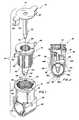
- FIG. 1is an exploded perspective view showing a self-tapping tee in accordance with the present invention, said self-tapping tee including a mandrel, coupling tap and saddle;
- FIG. 2is a side elevation, partly in section, showing the mandrel, coupling tap and saddle installed on a line;
- FIG. 3is a side elevation showing the mandrel being withdrawn from the coupling tap after the coupling tap and saddle have been installed on the line;
- FIG. 4is a side elevation showing the coupling tap and saddle installed on a smaller line
- FIG. 5 ais a detail on an enlarged scale taken along line 5 a - 5 a in FIG. 3 showing how the sidewall of the line about the hole poked by the coupling tap is stretched around the stem of the tap forming a seal;
- FIG. 5 bshows a seal with the addition of an o-ring
- FIG. 5 cshows a seal with the addition of glue
- FIG. 6is an exploded perspective view showing a driver for the mandrel with the same coupling tap as shown in the previous drawings but with a different saddle;
- FIG. 7is an exploded view of a driver-mandrel combination illustrated in use with a coupling tap having a truncated stem;
- FIG. 8is a perspective view on an enlarged scale of one of two identical halves of the saddle shown in FIG. 6;
- FIG. 9is an exploded side elevation of another self-tapping tee with a different mandrel, coupling tap and saddle than shown in the other figures;
- FIG. 10is a side elevation of a further coupling tap.
- FIG. 11is a cross-section taken along line 11 — 11 in FIG. 9 .
- reference numeral 10refers to a self-tapping tee for use in tapping heavy walled plastic pipe such as PVC and thick walled polyethylene tubing.
- heavy walledrefers to plastic pipe or tubing that is difficult to penetrate because of the material of which it is made (e.g., PVC) or because of wall thickness (e.g., thick walled polyethylene, polypropylene, polybutylene or the like).
- Light walled pipe or tubingrefers to polyethylene tubing having a wall thickness up to about 0.100 inch, as well as other materials having a similar resistance to puncture.
- heavy walled pipeincludes Class 160 and 200 PVC pipe and polyethylene tubing having a wall thickness between about 0.135 and 0.200 inch.
- Self-tapping tee 10in major part includes a saddle 12 , a plastic coupling tap 14 and a mandrel 16 .
- Saddle 12has a housing 18 mounted on a clamp 20 for gripping a line 22 being tapped.
- clamp 20preferably closes around line 22 but may grip the line sufficiently without encircling it if the clamp is glued to the line.
- Housing 18has a central bore 24 and internal threads 26 .
- Three illustrative saddles 12(FIGS. 1 - 4 ), 12 ′ (FIG. 6) and 12 ′′ (FIG. 9) are shown in the drawings, the invention, however, is not limited to the particular saddles shown as will become more apparent.
- Saddle 12as shown in FIGS. 1-4, and saddle 12 ′′ as shown in FIG. 9 are described in U.S. Pat. No. 5,694,972 to King.
- Clamp 20has a pair of opposing, arcuate clamp segments 28 having upper, lower and intermediate portions 28 U, 28 L, and 28 I, respectively.
- Clamp segments 28are attached on opposite sides of housing 18 .
- Each segment 28 as shown in FIGS. 1-4, or at least one segment, of clampis hinged at 30 along its intermediate portion 28 I, opposite the clamp segment which it opposes, to an arm 32 which depends from housing 18 .
- hinge 30is closer to upper portion 28 U than lower portion 28 L, facilitating entry of line 22 through the gap between the open segments.
- the pipe or tubingmakes contact with upper portions 28 U, causing lower portions 28 L to pivot about 30 , closing the clamp.
- Each of segments 28has a locking part 34 at the free end of its lower portion 28 L, cooperating with the locking part at the free end of the lower end portion 28 L of the other clamp segment.
- Both locking parts 34are of a substantially hook-like configuration, one curved inwardly and the other curved outwardly for interengagement.
- Locking parts 34provide locking means for interconnecting the clamp segments without tools when the clamp is pressed onto line 22 and may have several locking positions for use with different diameter pipe or tubing, over a selected range.
- Saddle 12 ′′shown in FIG. 9, is like saddle 12 except that arms 32 ′′ are elongated, for use as described below, and clamp segments 28 ′′ ( 28 ′′U, 28 ′′I and 28 ′′L) are smaller to accommodate smaller diameter pipe. Saddle 12 ′′ is particularly designed for use with smaller diameter pipe or the like.
- Saddle 12 ′is formed of two identical sections 12 a ′ and 12 b ′, one of which ( 12 a ′) is shown in FIG. 8 . Coupled together, sections 12 a ′ and 12 b ′ form a cylindrical housing 18 ′ divided into two identical housing sections 36 ′, 38 ′ and a clamp 20 ′ divided into two identical clamp sections 40 ′, 42 ′. Like saddle 20 , housing 18 ′ has a central bore 24 ′ with internal threads 26 ′ and is mounted on clamp 20 ′. At the parting line between housing sections 36 ′, 38 ′, one side is outfitted with a female latch member 53 ′, while the other side is outfitted with a male latch member 55 ′.
- Female latch member 53 ′has a pair of spaced sidewalls 57 ′ and male latch member 55 ′ has a resilient tongue 59 ′ and a head 61 ′ designed to latch between sidewalls 57 ′.
- one sideis provisioned with a radially, outwardly extending rib 44 ′, while the other side is provided with a second radially, outwardly extending rib 46 ′, a free end of which is hooked over to form a groove 48 ′.
- saddle 12 ′unlike saddle 12 , cannot be used on a range of different diameter lines 22 .
- Coupling tap 14may be made of metal but plastic is preferred and includes a hollow fitting 50 attached to a stem 52 .
- Stem 52is hollow and has at least one opening 54 in the stem.
- Fitting 50is externally threaded 56 and is cooperatively received in internal threads 26 of housing 24 , 24 ′ or the like.
- fitting 50has internal threads 58 , it may be used for coupling a branch line, riser or the like.
- a branch linecan be slip fitted into hollow fitting 50 and glued.
- Stem 52is conically tapered towards a first end 60 and attached to fitting 50 at a second end. When stem 52 comes to a point 62 , the point is preferably closed, with opening 54 located above.
- a transverse reinforcing web 64may be provided in point 62 .
- the tip of stem 52may be truncated for use as described hereinafter.
- fitting 50is a cylinder, larger in diameter than stem 52 , forming an abutment shoulder 66 at the junction therebetween.
- Fitting 50is preferably provided with one or more wing grips 68 located on its periphery to aid a user in twisting it into saddle 12 , saddle 12 ′ or the like.
- coupling tap 14 ′ as shown in FIG. 10may be a hollow fitting 50 ′ with barbs 51 ′.
- a further variation on coupling tapis shown in FIG.
- coupling tap 14 ′′has an abutment shoulder 67 ′′ on stem 52 ′′ and an annular seal 69 ′′ such as an o-ring or step grommet.
- Abutment shoulder 67 ′′spaces annular seal 69 ′′ (e.g., step grommet) a selected distance from fitting 50 ′′ for better sealing around the hole punched in the sidewall of line 22 .
- Abutment shoulder 67 ′′also works in concert with upper portions 28 ′′U of clamp 20 ′′ as a lock to prevent coupling tap 14 ′′ from laterally wobbling in saddle 12 ′′ and possibly breaking the seal.
- Mandrel 16has a shaft 70 that is received in hollow stem 52 of coupling tap 14 for reinforcement of the stem while coupling tap 14 is poking a hole 72 in line 22 .
- Shaft 70is sized for close fit in stem 52 and the tip of shaft 70 may be slotted 74 for receipt over web 64 (if present).
- Mandrel 16may be slipped or threaded into stem 52 and is removably attached to coupling tap 14 .
- shaft 70is attached to a cap 76 with a pair of downwardly depending arms 78 which push on grips 68 as coupling tap 14 is screwed into housing 18 . As seen in FIGS.
- each of arms 78includes a horizontally extending finger 80 , pointing in a direction for embracing the underside of grips 68 as coupling tap 14 is screwed into housing 18 .
- the force applied to grips 68may be increased when arms 78 extend beyond the ends of grips 68 , thus increasing the applied torque.
- a second mandrel 16 ′′is shown, which may be molded entirely of plastic.
- shaft 70 ′′is formed from two intersecting blades 71 ′′, mandrel 16 ′′ being otherwise similar to mandrel 16 .
- Coupling taps 14 , 14 ′ and 14 ′′are preferably made of a hard plastic such as ABS, nylon, PVC or the like, while saddles 12 , 12 ′ and 12 ′′ may be formed of a less rigid material such as polyethylene. It will be understood, however, that coupling taps 14 , 14 ′ and 14 ′′ and saddles 12 , 12 ′ and 12 ′′ may be formed of other functionally suitable materials not previously mentioned such as metal.
- Mandrel 16may be formed entirely of metal or partly of metal, for example with shaft 70 formed of a hard plastic such as used for coupling tap 14 . Suitable mandrels are also illustrated by mandrel 16 ′′ formed entirely of plastic.
- saddle 12is attached to heavy walled line 22 where a tee joint is desired.
- Coupling tap 14is threaded into housing 18 until grips 68 are stopped by barbs 96 on housing 18 .
- point 62 of stem 52 or shaft 70contacts a sidewall of line 22 and pokes through, the sidewall of the pipe or tubing around the hole stretched about the point, forming a seal 82 , best seen in detail FIG. 5 a .
- mandrel 16may be withdrawn from coupling tap 14 and a branch line or the like threaded into fitting 50 .
- Coupling tap 14 ′′, saddle 12 ′′ and mandrel 16 ′′ as shown in FIG. 9are used in a similar manner to their counterparts described above except that seal 82 is augmented by step grommet 69 ′′ or an o-ring 69 as shown in FIG. 5 b .
- Glue 73may be also be used, as shown in FIG. 5 c , with any of the coupling taps ( 14 , 14 ′, 14 ′′ or the like).
- Saddle 12 ′′which is spaced below housing 18 ′′ by arms 32 ′′ permits the use of the same length coupling tap 14 ′′ for a range of different sized lines 22 . This is advantageous when line 22 is made of stiff walled material such as PVC.
- clamp 20may pinch the line into an oval shape in cross-section, thereby facilitating the use of coupling tap 14 which would otherwise be too long and pierce both sides of the line.
- a driver 84may be used for reaching mandrel 16 when self-tapping tee 10 is installed on a line 22 , for example, deep within a hole.
- Driver 84includes a long handled shaft 86 with a t-bar 88 attached at a first end and with a head 90 at its second end. Head 90 may be slotted at 92 such that it straddles grips 68 and arms 78 . It will be understood that t-bar 88 increases the length of the lever arm, thus amplifying the force applied to coupling tap 14 .
- FIG. 7Another variation is shown in FIG. 7 . In this instance shaft 70 of mandrel 16 is integrally formed with a shaft 86 ′ of a second driver 84 ′.
- legs 94 ′can be used to push grips 68 in the same manner as arms 78 with t-bar 88 ′ amplifying the applied force.
- withdrawal of mandrel 16 ′increases the flow of water through stem 52 and line 22 as compared to a coupling tap with a closed point.
Landscapes
- Engineering & Computer Science (AREA)
- General Engineering & Computer Science (AREA)
- Mechanical Engineering (AREA)
- Branch Pipes, Bends, And The Like (AREA)
Abstract
Description
Claims (2)
Priority Applications (1)
| Application Number | Priority Date | Filing Date | Title |
|---|---|---|---|
| US09/809,947US6357472B1 (en) | 1999-11-05 | 2001-03-16 | Self-tapping tee |
Applications Claiming Priority (2)
| Application Number | Priority Date | Filing Date | Title |
|---|---|---|---|
| US09/434,729US6216723B1 (en) | 1999-11-05 | 1999-11-05 | Self-tapping tee |
| US09/809,947US6357472B1 (en) | 1999-11-05 | 2001-03-16 | Self-tapping tee |
Related Parent Applications (1)
| Application Number | Title | Priority Date | Filing Date |
|---|---|---|---|
| US09/434,729DivisionUS6216723B1 (en) | 1999-11-05 | 1999-11-05 | Self-tapping tee |
Publications (1)
| Publication Number | Publication Date |
|---|---|
| US6357472B1true US6357472B1 (en) | 2002-03-19 |
Family
ID=23725427
Family Applications (2)
| Application Number | Title | Priority Date | Filing Date |
|---|---|---|---|
| US09/434,729Expired - LifetimeUS6216723B1 (en) | 1999-11-05 | 1999-11-05 | Self-tapping tee |
| US09/809,947Expired - LifetimeUS6357472B1 (en) | 1999-11-05 | 2001-03-16 | Self-tapping tee |
Family Applications Before (1)
| Application Number | Title | Priority Date | Filing Date |
|---|---|---|---|
| US09/434,729Expired - LifetimeUS6216723B1 (en) | 1999-11-05 | 1999-11-05 | Self-tapping tee |
Country Status (1)
| Country | Link |
|---|---|
| US (2) | US6216723B1 (en) |
Cited By (18)
| Publication number | Priority date | Publication date | Assignee | Title |
|---|---|---|---|---|
| US6601605B2 (en)* | 2000-02-18 | 2003-08-05 | King Technology Of Missouri Inc. | Locking end cap |
| US6986532B1 (en)* | 2002-05-03 | 2006-01-17 | Tom King Harmony Products, Inc. | Saddle tee and tap for irrigation lines |
| US20060065306A1 (en)* | 2004-09-27 | 2006-03-30 | Mortensen Mark A | Removable, snap-on saddle and tap for irrigation pipes |
| ES2255357A1 (en)* | 2003-08-07 | 2006-06-16 | Francisco J. Villar Cloquell | Branching for fluid distribution network, has two guillotine structures for cutting section of each plastic tube |
| US20060169805A1 (en)* | 2005-01-28 | 2006-08-03 | Rajiv Dabir | Saddle tee and tool for irrigation lines |
| US20090140516A1 (en)* | 2007-11-29 | 2009-06-04 | King Jr L Herbert | Pipe saddle |
| US7832420B2 (en) | 2007-12-07 | 2010-11-16 | Orbit Irrigation Products, Inc. | Saddle tee |
| US8172276B1 (en) | 2006-10-06 | 2012-05-08 | Blazing Products, Inc. | Fittings connectable to end portions of pipes and related methods |
| US20120199318A1 (en)* | 2011-02-03 | 2012-08-09 | Delphi Technologies, Inc. | Assembly for fastening a fitting to a manifold |
| US8662541B2 (en) | 2009-04-01 | 2014-03-04 | Blazing Products, Inc. | Fittings for sealed retention to end portions of pipes and related methods |
| USD704302S1 (en)* | 2011-07-20 | 2014-05-06 | Richard Anderson | Piercing valve stem assembly |
| US9297486B2 (en) | 2006-10-06 | 2016-03-29 | Blazing Products, Inc. | Pipe fittings with insert retaining seals and related methods |
| US9593789B2 (en) | 2006-10-06 | 2017-03-14 | Blazing Products, Inc. | Pipe-fitting with adaptor assembly and related methods |
| US9661807B2 (en) | 2012-05-24 | 2017-05-30 | Rain Bird Corporation | Conduit with connector and assembly thereof |
| US9668431B2 (en) | 2013-11-22 | 2017-06-06 | Rain Bird Corporation | Conduit with connector and assembly thereof |
| CN110005894A (en)* | 2019-04-23 | 2019-07-12 | 孙华定 | A kind of circumscribed pipe fitting and its installation method |
| US10537073B2 (en) | 2012-05-24 | 2020-01-21 | Rain Bird Corporation | Conduit with connector and assembly thereof |
| US10801654B2 (en) | 2006-10-06 | 2020-10-13 | King Technology Of Missouri, Llc | Tubular pipe fitting insert with interior reinforcement ribs |
Families Citing this family (16)
| Publication number | Priority date | Publication date | Assignee | Title |
|---|---|---|---|---|
| US6681796B2 (en) | 2000-02-18 | 2004-01-27 | Lloyd Herbert King, Jr. | Drainage valve pipe tap assembly |
| US6510865B2 (en) | 2000-02-18 | 2003-01-28 | Lloyd Herbert King, Jr. | Tap and saddle for forming a hinged coupon |
| US6343616B1 (en)* | 2000-12-15 | 2002-02-05 | Charles R. Houtchens | Drip emitter attaching apparatus |
| US7150476B2 (en)* | 2002-05-03 | 2006-12-19 | Blazing Products, Inc. | Saddle tee and tap for irrigation lines |
| US6886585B1 (en)* | 2004-06-25 | 2005-05-03 | The Patent Store Llc | Soft grip drain |
| USD646950S1 (en)* | 2010-09-29 | 2011-10-18 | Colorado Great Grips, Inc. | Knob and handle gripping device |
| US9587778B2 (en)* | 2011-03-01 | 2017-03-07 | National Diversified Sales, Inc. | Clamp and spike for flexible conduit |
| AU2014362212A1 (en)* | 2013-12-13 | 2016-06-30 | Thomas A. King | Fittings for pipes, and presses for installing the fittings to pipes |
| EP3224526A1 (en) | 2014-11-21 | 2017-10-04 | Duane K. Smith | Fittings for irrigation systems |
| USD778410S1 (en)* | 2014-11-21 | 2017-02-07 | Duane K. Smith | Fenestrated tip for a spike tap of an irrigation fitting |
| GB2536960B (en)* | 2015-04-02 | 2021-02-24 | Exel Industries Sa | Irrigation connectors |
| USD783132S1 (en)* | 2015-11-20 | 2017-04-04 | Duane K. Smith | Fenestrated tip for a spike tap of an irrigation fitting |
| US10955074B2 (en)* | 2017-04-28 | 2021-03-23 | Nibco Inc. | Threaded pipe connections and sockets for making the same in situ |
| NO20170884A1 (en) | 2017-05-30 | 2018-06-25 | Talgoe Teknologi As | Apparatus for piercing an elongate tubular body and method of use of the apparatus |
| US11266336B2 (en) | 2018-06-11 | 2022-03-08 | Edwards Lifesciences Corporation | Attachment mechanism to attach a component to a particular location on a tube in a blood sampling-blood pressure monitoring system |
| IL290680A (en)* | 2022-02-17 | 2023-09-01 | Bekesher Letipul Ltd | Irrigation device |
Citations (5)
| Publication number | Priority date | Publication date | Assignee | Title |
|---|---|---|---|---|
| US607517A (en)* | 1898-07-19 | Pipe-coupling and patch | ||
| US635534A (en)* | 1899-05-31 | 1899-10-24 | Albert Florin | Device for connecting tubes. |
| US4239265A (en)* | 1978-09-15 | 1980-12-16 | King Lloyd H Sr | Attachments for pipes |
| US5105844A (en)* | 1990-09-24 | 1992-04-21 | King Lloyd H Sr | Two step branch forming attachment |
| US5694972A (en)* | 1996-06-27 | 1997-12-09 | Tom King Harmony Products, Inc. | Saddle tee for irrigation lines |
Family Cites Families (23)
| Publication number | Priority date | Publication date | Assignee | Title |
|---|---|---|---|---|
| US2344163A (en) | 1941-07-02 | 1944-03-14 | M B Skinner Company | Service connector |
| US3240434A (en) | 1964-01-13 | 1966-03-15 | Ralph F Bradley | Irrigation nozzle |
| US3349792A (en) | 1965-02-24 | 1967-10-31 | Phillips Petroleum Co | Tapping t and valve |
| US3448758A (en) | 1966-11-04 | 1969-06-10 | John W Mullins | Refrigerant service valve |
| US3756261A (en)* | 1971-11-16 | 1973-09-04 | Amp Inc | Method and apparatus for connecting a tap to a pipeline |
| US3973732A (en) | 1971-12-30 | 1976-08-10 | Diggs Richard E | Quick-connect fittings for a trickle type irrigation system |
| US3834628A (en) | 1972-04-25 | 1974-09-10 | H Selman | Trickle irrigation device |
| US3806031A (en) | 1973-07-05 | 1974-04-23 | D Olson | Snap-on emitter |
| US3920037A (en) | 1974-04-29 | 1975-11-18 | Int Ag | Drip irrigation tap and system |
| CA1037512A (en) | 1974-08-12 | 1978-08-29 | Thomas Pessia | Tapping t for plastic pipe |
| US3978881A (en) | 1975-06-05 | 1976-09-07 | The Westward Company | Gas line pierce valve |
| US4029118A (en)* | 1975-07-03 | 1977-06-14 | Phillips Petroleum Company | Tapping apparatus and method |
| US3995655A (en)* | 1975-10-07 | 1976-12-07 | Mueller Co. | Apparatus for and method of making a service line connection through a fitting |
| US4112944A (en) | 1976-12-13 | 1978-09-12 | Williams Gayland M | Tube clamp and piercing device |
| US4121771A (en) | 1977-01-17 | 1978-10-24 | Hendrickson Ralph L | Drip irrigation emitter |
| US4294470A (en) | 1978-12-11 | 1981-10-13 | Reed Irrigation Systems Pty Ltd. | In-line tube junctions |
| US4522339A (en) | 1983-06-03 | 1985-06-11 | Ris Irrigation Systems | Irrigation fitting with installation barb and associated barb installation tool |
| CA1321806C (en) | 1989-09-27 | 1993-08-31 | Dominique Lesquir | Connector for sap collecting system |
| US5169177A (en) | 1991-01-18 | 1992-12-08 | Victaulic Company Of America | Quick connect branch connector |
| US5123627A (en) | 1991-03-20 | 1992-06-23 | Hodges B Eugene | Condensate drain fitting with check valve and stepped diameters to fit different pipe sizes |
| US5095564A (en) | 1991-06-27 | 1992-03-17 | Kruger Jay C | Saddle tee for irrigation pipe |
| US5322083A (en) | 1993-09-13 | 1994-06-21 | Olivier Rick A | Refrigerant pipe piercing valve apparatus |
| US5425395A (en)* | 1994-09-13 | 1995-06-20 | Perfection Corporation | Tapping tee assembly |
- 1999
- 1999-11-05USUS09/434,729patent/US6216723B1/ennot_activeExpired - Lifetime
- 2001
- 2001-03-16USUS09/809,947patent/US6357472B1/ennot_activeExpired - Lifetime
Patent Citations (5)
| Publication number | Priority date | Publication date | Assignee | Title |
|---|---|---|---|---|
| US607517A (en)* | 1898-07-19 | Pipe-coupling and patch | ||
| US635534A (en)* | 1899-05-31 | 1899-10-24 | Albert Florin | Device for connecting tubes. |
| US4239265A (en)* | 1978-09-15 | 1980-12-16 | King Lloyd H Sr | Attachments for pipes |
| US5105844A (en)* | 1990-09-24 | 1992-04-21 | King Lloyd H Sr | Two step branch forming attachment |
| US5694972A (en)* | 1996-06-27 | 1997-12-09 | Tom King Harmony Products, Inc. | Saddle tee for irrigation lines |
Cited By (27)
| Publication number | Priority date | Publication date | Assignee | Title |
|---|---|---|---|---|
| US6601605B2 (en)* | 2000-02-18 | 2003-08-05 | King Technology Of Missouri Inc. | Locking end cap |
| US6986532B1 (en)* | 2002-05-03 | 2006-01-17 | Tom King Harmony Products, Inc. | Saddle tee and tap for irrigation lines |
| ES2255357B1 (en)* | 2003-08-07 | 2007-09-16 | Francisco J. Villar Cloquell | DERIVATION FOR FLUID DISTRIBUTION NETWORKS IN LOAD IN PLASTIC MATERIAL PIPES. |
| ES2255357A1 (en)* | 2003-08-07 | 2006-06-16 | Francisco J. Villar Cloquell | Branching for fluid distribution network, has two guillotine structures for cutting section of each plastic tube |
| US20060065306A1 (en)* | 2004-09-27 | 2006-03-30 | Mortensen Mark A | Removable, snap-on saddle and tap for irrigation pipes |
| US7150289B2 (en) | 2004-09-27 | 2006-12-19 | Duane D. Robertson | Removable, snap-on saddle and tap for irrigation pipes |
| US7219684B2 (en) | 2005-01-28 | 2007-05-22 | Rain Bird Corporation | Saddle tee and tool for irrigation lines |
| US20060169805A1 (en)* | 2005-01-28 | 2006-08-03 | Rajiv Dabir | Saddle tee and tool for irrigation lines |
| US10801654B2 (en) | 2006-10-06 | 2020-10-13 | King Technology Of Missouri, Llc | Tubular pipe fitting insert with interior reinforcement ribs |
| US9593789B2 (en) | 2006-10-06 | 2017-03-14 | Blazing Products, Inc. | Pipe-fitting with adaptor assembly and related methods |
| US8172276B1 (en) | 2006-10-06 | 2012-05-08 | Blazing Products, Inc. | Fittings connectable to end portions of pipes and related methods |
| US9297486B2 (en) | 2006-10-06 | 2016-03-29 | Blazing Products, Inc. | Pipe fittings with insert retaining seals and related methods |
| US8596691B2 (en) | 2006-10-06 | 2013-12-03 | Blazing Products, Inc. | Fittings connectable to end portions of pipes and related methods |
| USD709994S1 (en) | 2007-10-05 | 2014-07-29 | Blazing Products, Inc. | Insert portion of a pipe fitting |
| US20090140516A1 (en)* | 2007-11-29 | 2009-06-04 | King Jr L Herbert | Pipe saddle |
| US8196599B2 (en) | 2007-12-07 | 2012-06-12 | Orbit Irrigation Products, Inc. | Saddle tee |
| US20110127764A1 (en)* | 2007-12-07 | 2011-06-02 | Scot Hoskisson | Saddle tee |
| US7832420B2 (en) | 2007-12-07 | 2010-11-16 | Orbit Irrigation Products, Inc. | Saddle tee |
| US8662541B2 (en) | 2009-04-01 | 2014-03-04 | Blazing Products, Inc. | Fittings for sealed retention to end portions of pipes and related methods |
| US8882155B2 (en)* | 2011-02-03 | 2014-11-11 | Delphi Technologies, Inc. | Assembly for fastening a fitting to a manifold |
| US20120199318A1 (en)* | 2011-02-03 | 2012-08-09 | Delphi Technologies, Inc. | Assembly for fastening a fitting to a manifold |
| USD704302S1 (en)* | 2011-07-20 | 2014-05-06 | Richard Anderson | Piercing valve stem assembly |
| US9661807B2 (en) | 2012-05-24 | 2017-05-30 | Rain Bird Corporation | Conduit with connector and assembly thereof |
| US10537073B2 (en) | 2012-05-24 | 2020-01-21 | Rain Bird Corporation | Conduit with connector and assembly thereof |
| US9668431B2 (en) | 2013-11-22 | 2017-06-06 | Rain Bird Corporation | Conduit with connector and assembly thereof |
| CN110005894A (en)* | 2019-04-23 | 2019-07-12 | 孙华定 | A kind of circumscribed pipe fitting and its installation method |
| CN110005894B (en)* | 2019-04-23 | 2021-11-05 | 浙江晨馨阀门有限公司 | External pipe joint and mounting method thereof |
Also Published As
| Publication number | Publication date |
|---|---|
| US6216723B1 (en) | 2001-04-17 |
Similar Documents
| Publication | Publication Date | Title |
|---|---|---|
| US6357472B1 (en) | Self-tapping tee | |
| US5694972A (en) | Saddle tee for irrigation lines | |
| US5577529A (en) | Tapping fittings | |
| US6672628B2 (en) | Quick connect hose coupling | |
| US8196599B2 (en) | Saddle tee | |
| US2641489A (en) | Coupling construction | |
| US5934817A (en) | Coupling arrangement for a vehicle door lock assembly | |
| US20040113425A1 (en) | Saddle tee and tap for irrigation lines | |
| US6416085B1 (en) | Pressurized hose coupling | |
| US239827A (en) | Hose-coupling | |
| CA2449857A1 (en) | Wear sleeve | |
| US6601605B2 (en) | Locking end cap | |
| WO2004092630A3 (en) | Non-damming coupler | |
| US4922951A (en) | Service tee for connection to a gas or water main | |
| AU691922B2 (en) | A pipe coupling | |
| EP0957234A3 (en) | Circulating nipple and method for setting well casing | |
| JPH10328919A (en) | Boring cutter | |
| KR200220906Y1 (en) | The branch connecting tool of water pipe in soft-vinyl class | |
| US2926026A (en) | Conduit connector | |
| JP2546408Y2 (en) | Cock for plumbing | |
| JP2799188B2 (en) | How to repair plastic pipes | |
| EP4502446A1 (en) | Hose connection adaptor | |
| KR960018318A (en) | Flow restrictor for hose fitting | |
| KR940004630Y1 (en) | Pipe connector | |
| KR200280020Y1 (en) | Nipple for a nylon and urethane hosepipe |
Legal Events
| Date | Code | Title | Description |
|---|---|---|---|
| STCF | Information on status: patent grant | Free format text:PATENTED CASE | |
| FEPP | Fee payment procedure | Free format text:PAYOR NUMBER ASSIGNED (ORIGINAL EVENT CODE: ASPN); ENTITY STATUS OF PATENT OWNER: SMALL ENTITY | |
| FPAY | Fee payment | Year of fee payment:4 | |
| FPAY | Fee payment | Year of fee payment:8 | |
| FPAY | Fee payment | Year of fee payment:12 | |
| AS | Assignment | Owner name:BLAZING PRODUCTS, INC., MISSOURI Free format text:CHANGE OF NAME;ASSIGNOR:TOM KING HARMONY PRODUCTS, INC.;REEL/FRAME:045841/0013 Effective date:20031007 Owner name:KING TECHNOLOGY OF MISSOURI, INC., MISSOURI Free format text:ASSIGNMENT OF ASSIGNORS INTEREST;ASSIGNOR:BLAZING PRODUCTS, INC.;REEL/FRAME:045841/0098 Effective date:20171120 | |
| AS | Assignment | Owner name:ROYAL BANK OF CANADA, AS ADMINISTRATIVE AGENT, CANADA Free format text:FIRST LIEN INTELLECTUAL PROPERTY SECURITY AGREEMENT;ASSIGNOR:KING TECHNOLOGY OF MISSOURI, LLC;REEL/FRAME:046216/0193 Effective date:20180522 Owner name:ROYAL BANK OF CANADA, AS ADMINISTRATIVE AGENT, CAN Free format text:FIRST LIEN INTELLECTUAL PROPERTY SECURITY AGREEMENT;ASSIGNOR:KING TECHNOLOGY OF MISSOURI, LLC;REEL/FRAME:046216/0193 Effective date:20180522 | |
| AS | Assignment | Owner name:WILMINGTON TRUST, NATIONAL ASSOCIATION, AS ADMINISTRATIVE AGENT, DELAWARE Free format text:SECURITY INTEREST;ASSIGNOR:KING TECHNOLOGY OF MISSOURI, LLC;REEL/FRAME:045897/0977 Effective date:20180522 Owner name:WILMINGTON TRUST, NATIONAL ASSOCIATION, AS ADMINIS Free format text:SECURITY INTEREST;ASSIGNOR:KING TECHNOLOGY OF MISSOURI, LLC;REEL/FRAME:045897/0977 Effective date:20180522 | |
| AS | Assignment | Owner name:KING TECHNOLOGY OF MISSOURI, LLC, MISSOURI Free format text:TERMINATION AND RELEASE OF SECURITY INTEREST IN INTELLECTUAL PROPERTY;ASSIGNOR:ROYAL BANK OF CANADA;REEL/FRAME:046761/0595 Effective date:20180809 Owner name:KING TECHNOLOGY OF MISSOURI, LLC, MISSOURI Free format text:TERMINATION AND RELEASE OF SECURITY INTEREST IN SECOND LIEN INTELLECTUAL PROPERTY COLLATERAL;ASSIGNOR:WILMINGTON TRUST, NATIONAL ASSOCIATION, AS ADMINISTRATIVE AGENT;REEL/FRAME:046762/0718 Effective date:20180809 | |
| AS | Assignment | Owner name:KING TECHNOLOGY OF MISSOURI, LLC, MISSOURI Free format text:CHANGE OF NAME;ASSIGNOR:KING TECHNOLOGY OF MISSOURI, INC.;REEL/FRAME:048039/0597 Effective date:20180518 | |
| AS | Assignment | Owner name:TOM KING HARMONY PRODUCTS, INC., MISSOURI Free format text:ASSIGNMENT OF ASSIGNORS INTEREST;ASSIGNOR:KING, THOMAS A.;REEL/FRAME:049984/0917 Effective date:20010111 | |
| AS | Assignment | Owner name:ANTARES CAPITAL LP, AS AGENT, ILLINOIS Free format text:SECURITY INTEREST;ASSIGNORS:ECM INDUSTRIES, LLC;KING TECHNOLOGY OF MISSOURI, LLC;THE PATENT STORE, LLC;REEL/FRAME:051404/0833 Effective date:20191223 | |
| AS | Assignment | Owner name:ANTARES CAPITAL LP, AS AGENT, ILLINOIS Free format text:RELEASE BY SECURED PARTY;ASSIGNORS:ECM INDUSTRIES, LLC;KING TECHNOLOGY OF MISSOURI, LLC;THE PATENT STORE, LLC;REEL/FRAME:064501/0438 Effective date:20230518 | |
| AS | Assignment | Owner name:THE PATENT STORE, LLC, MISSOURI Free format text:CORRECTIVE ASSIGNMENT TO CORRECT THE CONVEY PARTY TO ANTARES CAPITAL LP AND RECEIVE PARTY TO ECM INDUSTRIES, LLC, KING TECHNOLOGY OF MISSOURI, LLC, THE PATENT STORE, LLC PREVIOUSLY RECORDED ON REEL 064501 FRAME 0438. ASSIGNOR(S) HEREBY CONFIRMS THE RELEASE OF SECURITY INTEREST;ASSIGNOR:ANTARES CAPITAL LP, AS AGENT;REEL/FRAME:064718/0894 Effective date:20230518 Owner name:KING TECHNOLOGY OF MISSOURI, LLC, MISSOURI Free format text:CORRECTIVE ASSIGNMENT TO CORRECT THE CONVEY PARTY TO ANTARES CAPITAL LP AND RECEIVE PARTY TO ECM INDUSTRIES, LLC, KING TECHNOLOGY OF MISSOURI, LLC, THE PATENT STORE, LLC PREVIOUSLY RECORDED ON REEL 064501 FRAME 0438. ASSIGNOR(S) HEREBY CONFIRMS THE RELEASE OF SECURITY INTEREST;ASSIGNOR:ANTARES CAPITAL LP, AS AGENT;REEL/FRAME:064718/0894 Effective date:20230518 Owner name:ECM INDUSTRIES, LLC, WISCONSIN Free format text:CORRECTIVE ASSIGNMENT TO CORRECT THE CONVEY PARTY TO ANTARES CAPITAL LP AND RECEIVE PARTY TO ECM INDUSTRIES, LLC, KING TECHNOLOGY OF MISSOURI, LLC, THE PATENT STORE, LLC PREVIOUSLY RECORDED ON REEL 064501 FRAME 0438. ASSIGNOR(S) HEREBY CONFIRMS THE RELEASE OF SECURITY INTEREST;ASSIGNOR:ANTARES CAPITAL LP, AS AGENT;REEL/FRAME:064718/0894 Effective date:20230518 |