US6357025B1 - Testing and burn-in of IC chips using radio frequency transmission - Google Patents
Testing and burn-in of IC chips using radio frequency transmissionDownload PDFInfo
- Publication number
- US6357025B1 US6357025B1US09/675,452US67545200AUS6357025B1US 6357025 B1US6357025 B1US 6357025B1US 67545200 AUS67545200 AUS 67545200AUS 6357025 B1US6357025 B1US 6357025B1
- Authority
- US
- United States
- Prior art keywords
- circuitry
- integrated circuit
- interrogator unit
- test
- radio communication
- Prior art date
- Legal status (The legal status is an assumption and is not a legal conclusion. Google has not performed a legal analysis and makes no representation as to the accuracy of the status listed.)
- Expired - Lifetime
Links
Images


Classifications
- G—PHYSICS
- G01—MEASURING; TESTING
- G01R—MEASURING ELECTRIC VARIABLES; MEASURING MAGNETIC VARIABLES
- G01R31/00—Arrangements for testing electric properties; Arrangements for locating electric faults; Arrangements for electrical testing characterised by what is being tested not provided for elsewhere
- G01R31/28—Testing of electronic circuits, e.g. by signal tracer
- G01R31/302—Contactless testing
- G01R31/303—Contactless testing of integrated circuits
- G—PHYSICS
- G01—MEASURING; TESTING
- G01R—MEASURING ELECTRIC VARIABLES; MEASURING MAGNETIC VARIABLES
- G01R31/00—Arrangements for testing electric properties; Arrangements for locating electric faults; Arrangements for electrical testing characterised by what is being tested not provided for elsewhere
- G01R31/01—Subjecting similar articles in turn to test, e.g. "go/no-go" tests in mass production; Testing objects at points as they pass through a testing station
- G—PHYSICS
- G01—MEASURING; TESTING
- G01R—MEASURING ELECTRIC VARIABLES; MEASURING MAGNETIC VARIABLES
- G01R31/00—Arrangements for testing electric properties; Arrangements for locating electric faults; Arrangements for electrical testing characterised by what is being tested not provided for elsewhere
- G01R31/28—Testing of electronic circuits, e.g. by signal tracer
- G01R31/282—Testing of electronic circuits specially adapted for particular applications not provided for elsewhere
- G01R31/2822—Testing of electronic circuits specially adapted for particular applications not provided for elsewhere of microwave or radiofrequency circuits
- G—PHYSICS
- G01—MEASURING; TESTING
- G01R—MEASURING ELECTRIC VARIABLES; MEASURING MAGNETIC VARIABLES
- G01R31/00—Arrangements for testing electric properties; Arrangements for locating electric faults; Arrangements for electrical testing characterised by what is being tested not provided for elsewhere
- G01R31/28—Testing of electronic circuits, e.g. by signal tracer
- G01R31/302—Contactless testing
- G01R31/3025—Wireless interface with the DUT
- G—PHYSICS
- G06—COMPUTING OR CALCULATING; COUNTING
- G06K—GRAPHICAL DATA READING; PRESENTATION OF DATA; RECORD CARRIERS; HANDLING RECORD CARRIERS
- G06K19/00—Record carriers for use with machines and with at least a part designed to carry digital markings
- G06K19/06—Record carriers for use with machines and with at least a part designed to carry digital markings characterised by the kind of the digital marking, e.g. shape, nature, code
- G06K19/067—Record carriers with conductive marks, printed circuits or semiconductor circuit elements, e.g. credit or identity cards also with resonating or responding marks without active components
- G06K19/07—Record carriers with conductive marks, printed circuits or semiconductor circuit elements, e.g. credit or identity cards also with resonating or responding marks without active components with integrated circuit chips
- G06K19/0701—Record carriers with conductive marks, printed circuits or semiconductor circuit elements, e.g. credit or identity cards also with resonating or responding marks without active components with integrated circuit chips at least one of the integrated circuit chips comprising an arrangement for power management
- G—PHYSICS
- G06—COMPUTING OR CALCULATING; COUNTING
- G06K—GRAPHICAL DATA READING; PRESENTATION OF DATA; RECORD CARRIERS; HANDLING RECORD CARRIERS
- G06K7/00—Methods or arrangements for sensing record carriers, e.g. for reading patterns
- G06K7/0095—Testing the sensing arrangement, e.g. testing if a magnetic card reader, bar code reader, RFID interrogator or smart card reader functions properly
Definitions
- This inventionrelates to systems for testing integrated circuit chips. This invention also relates to methods for conducting such tests.
- Processed semiconductor waferstypically comprise an array of substantially isolated integrated circuitry which are individually referred to as “die”.
- the “die”are also commonly referred to as “chips” and comprise the finished circuitry components of, for example, processors and memory circuits.
- Common types of memory circuitsinclude DRAM and SRAM chips.
- the typical test procedure for DRAM or SRAM circuitryis to first etch the upper protective passivation layer to expose desired bonding pads on the individual die. Thereafter, the wafer is subjected to test probing whereby the individual die are tested for satisfactory operation. Inoperable die are typically marked by an ink mark. After testing, the wafer is severed between individual chips. The operable, non-marked die are collected.
- the operable individual dieare then assembled in final packages of either ceramic or plastic.
- the dieare loaded into burn-in boards which comprise printed circuit boards having individual sockets.
- the burn-in boardsare placed into a bum-in oven, and the parts are subjected to burn-in testing during which the die are operated for a period of time at different temperature cycles, including high temperatures.
- the dieare stressed to accelerate their lives in an effort to identify the weak die which are likely to fail. Manufacturers predict early failures, known as “infant mortalities”, to occur within a predetermined period of time of the burn-in cycle. Burn-in testing is conducted for a period of time sufficient to reveal these infant mortalities.
- the dieare subjected to a preliminary wafer-level test before severing, and a burn-in test after severing and packaging of the individual dies
- a preliminary wafer-level test before severingand a burn-in test after severing and packaging of the individual dies
- Each of these two separate testsrequire some physical connection with testing apparatus.
- the wafer-level testbefore severing individual die
- portions of the wafer passivationare removed to expose test bonding pads, and then test probes are employed to directly contact these test bonding pads.
- test probesare employed to directly contact these test bonding pads.
- each individual chipmust be inserted into burn-in boards for the test.
- This inventionprovides a system and method for preliminary wafer-level testing and burn-in testing without physically contacting the semiconductor wafer or individual die.
- FIG. 1is a diagrammatic illustration of a testing system according to one aspect of the present invention.
- FIG. 2is a diagrammatic illustration of a testing system according to another aspect of this invention.
- FIG. 3is a block diagram illustrating the radio frequency communication system according to the present invention.
- a testing system for evaluating an integrated circuit chipcomprises.
- interrogator unithaving a radio communication range, the interrogator unit comprising data evaluation means for transmitting interrogating information via radio communication and for receiving test data via radio communication;
- test interface circuitryelectrically coupled to the operational circuitry and including means for receiving the interrogating information from the data evaluation means of the interrogator unit, the test interface circuitry test cycling the operational a circuitry according to the interrogating information, the test interface circuitry including means for transmitting via radio communication test data output by the operational circuitry in response to the interrogating information back to the data evaluation means of the interrogator unit;
- the data evaluation meansincluding means for examining the test data to determine whether the integrated circuit chip has a defect.
- the testing systemfurther comprises:
- an RF isolating housingfor holding the interrogator unit and the integrated circuit chip, the housing defining a chamber which allows radio communication between the interrogator unit and the integrated circuit chip while blocking RF signals exterior to the housing from entering the chamber.
- the data evaluation means of the interrogator unitincludes a means for providing an identification code as part of the interrogating information, an integrated circuit chip further comprises:
- tag meansfor storing an ID label identifying the integrated circuit chip
- test interface meansincluding discriminating means for comparing the identification code sent by the data evaluation means with the ID label stored by the tag means, the test interface means test cycling the operational circuitry when the identification code matches the ID label.
- a testing system for evaluating integrated circuit chipscomprises:
- power transfer meansfor transmitting via radio communication a power signal having a power inducing frequency and amplitude
- data evaluation meansfor transmitting interrogating information via radio communication and for receiving test data via radio communication
- power circuitryelectrically coupled to the operational circuitry and including means for receiving the power signal from the power transfer means of the interrogator unit, the power circuitry generating power from the power signal and supplying the power to the operational circuitry;
- test interface circuitryelectrically coupled to the operational circuitry and including means for receiving the interrogating information from the data evaluation means of the interrogator unit, the test interface circuitry test cycling the operational a circuitry according to the interrogating information, the test interface circuitry including means for transmitting via radio communication test data output by the operational circuitry in response to the interrogating information back to the data evaluation means of the interrogator unit;
- the data evaluation meansincluding means for examining the test data to determine whether the integrated circuit chip has a defect.
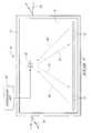
- FIG. 1diagrammatically illustrates a testing system according to one embodiment of this invention.
- the testing system of this inventionis designed to test multiple die or integrated circuit (IC) chips at is different phases of the manufacturing process. For example, the IC chips can be evaluated at the semiconductor wafer level, or after separation into individual die, or after packaging of the individual die.
- This testing systemevaluates individual integrated circuits in a contactless manner without the use of probes or burn-in test boards. Instead, this testing system employs radio communication to interrogate individual IC chips without physically contacting them.
- Testing system 10is shown as simultaneously evaluating multiple integrated circuit chips 12 .
- System 10includes radio frequency (RF) isolated housing 14 , such as a grounded conductive shielding, which is impervious to interfering RF signals.
- Housing 14defines a chamber 16 which holds IC chips 12 .
- RF isolated housing 14prevents RF signals 18 , which originate external to housing 14 , from entering into chamber 16 . In this manner, the radio-based testing is conducted free of external interference or other unwanted noise.
- RFradio frequency
- Testing system 10has an interrogator unit 20 (described below in more detail) provided outside housing 14 and a transmitting device 22 provided within housing 14 .
- Transmitting device 22is preferably an omni-directional antenna of sufficient dimensions to emit RF signals 24 to IC chips 12 .
- the strength of the RE signal and the proximity of the IC chips to antenna 22are such that all IC chips 12 are in radio communication with interrogator unit 20 .
- RF isolated housing 14facilitates radio communication within chamber 16 while blocking external RF signals 18 from entering the chamber.
- Individual IC chipscontain RF receiving and transmitting circuitry which allows the IC chips to receive RF signals 24 from interrogator unit 20 and to transmit RE signals 26 back to interrogator unit 20 via antenna 22 .
- the RF circuitryconsumes very little space on each IC circuit.
- Interrogator unit 20transmits both power signals to energize the IC chips 12 and data information to test the IC chips 12 . In this manner, the testing system can evaluate IC chips positioned remotely from interrogator unit 20 , but within the radio communication range.
- Such contactless testingis suitable at many different manufacturing stages, thereby eliminating mechanical probes or other test equipment which require physically contacting the individual IC chips.
- Interrogator unit 20is preferably positioned outside of RF isolated housing 14 and electrically coupled to antenna 22 which remains within chamber 16 .
- Interrogator unit 20may comprise, for example, a computer (such as a work station or PC) which is adapted with an RF communication circuit board and programmed to conduct the various tests on IC chips 12 .
- interrogator unit 20may be positioned inside housing 14 , such as a specially designed electronic component which can be mounted therein.
- testing system 10simultaneously evaluates numerous IC chips 12 , individual IC chips are provided with an identification scheme which permits interrogator unit 20 to identify and discriminate against certain IC chips.
- Various available protocolsmay be used to eliminate simultaneous identification among two or more IC chips.
- One known methodis the Computer Network Communications Protocol which sequentially eliminates IC chips until the desired chip is discovered.
- One preferred identification schemeis discussed below in more detail.
- FIG. 2illustrates a testing system 30 according to a second embodiment of this invention.
- Testing system 30includes an interrogator unit 20 coupled to a directional antenna 32 .
- Testing system 30further includes a support chuck or platform 34 , which preferably comprises a positionally controllable platform that moves IC chips 12 at a selected pace beneath directional antenna 32 .
- interrogator unit 20evaluates individual IC chips in an individually selectable manner.
- Directional antenna 32transmits and receives RF signals 36 from a single IC chip 12 .
- antenna 32can be designed to be moved physically or electronically relative to stationary IC chips 12 .
- Evaluating IC chips using radio frequency transmissionprovides a number of advantages.
- a second advantageis that more chips can be evaluated at a higher rate. During burn-in testing, for example, substantially more IC chips can be placed in an oven for burn-in because the testing system no longer needs to contact each individual chip. This improves testing efficiency.
- a third advantageis that precise electrical connection to tiny contacts on every IC chip is not required for testing.
- a fourth advantageis that parametric and/or live circuit information which is being generated under harsh environmental conditions can be monitored in real time without using IC contacts.
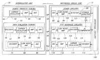
- FIG. 3is a block diagram of an interrogator unit 20 and an integrated circuit chip 12 constructed according to one embodiment of this invention.
- Interrogator unit 20includes a power transfer subunit 40 and a data evaluation subunit 50 .
- Integrated circuit chip 12includes power circuitry 80 which interacts with power transfer subunit 40 of interrogator unit 20 , and test interface circuitry 100 which interacts with data evaluation subunit 50 of interrogator unit 20 .
- IC chip 12further includes operational circuitry 130 which consists of the components and elements for which the IC chip 12 is designed.
- operational circuitry 130represents the memory cells and peripheral cells of a RAM or ROM chip. Operational circuitry 130 may also represent the control logic of a microcontroller or other intelligent IC chip.
- Power transfer subunit 40includes carrier oscillator circuitry 42 which generates an RF “power” signal of a selected frequency, an amplifier 44 which amplifies the power signal and an antenna 46 to transmit the power signal (represented by arrow 48 ) to IC chip 12 .
- Carrier oscillator 42 , amplifier 44 , and antenna 46provide a power transfer means for transmitting via radio communication a power signal having a power inducing frequency and amplitude.
- Data evaluation subunit 50includes a data transmission component 52 which is responsible for transmitting test data to test interface circuitry 100 of IC chip 12 and a data reception component 54 which is dedicated to receiving information indicative of the test results from test interface circuitry 100 .
- Data transmission component 52includes an encoder 56 , a carrier oscillator 58 , an amplifier 60 , and an antenna 62 .
- Encoder 56converts the desired testing instructions into a compatible data format of serial bits which are then applied to a carrier frequency and transmitted as an interrogating information signal (represented as arrow 64 ) to IC chip 12 .
- the information provided by encoder 56may also contain an identification code for selecting a specific IC chip 12 or a specific class of chips.
- Data reception component 54has an antenna 66 , a low-noise amplifier 68 , and a decoder 70 .
- data evaluation subunit 50provides a means for transmitting interrogating information via radio communication to IC chip 12 and for receiving test data via radio communication from IC chip 12 .
- Power circuitry 80 of IC chip 12has an antenna 82 , a low-noise amplifier 84 , a detector 86 , and a storage capacitor 88 .
- the power signal 48 transmitted by power transfer subunit 40is received by antenna 82 and amplified. Energy is captured from the oscillating signal and stored by capacitor 88 . This energy is then supplied to operational circuitry 130 to provide power during the testing procedures.
- the IC chipmay be powered independently of the power signal transmitted by power transfer subunit 40 .
- powermay be supplied directly to the IC chip via some external socket or probe.
- interrogator unit 20can be constructed without power transfer subunit 40 .
- Test interface circuitry 100includes a data reception component 102 which receives the interrogating information 64 from data evaluation subunit 50 and data transmission component 104 which transmits test results back to data evaluation subunit 50 .
- Data reception component 102has an antenna 106 , a low-noise amplifier 108 , and a decoder 110 .
- the interrogating information 64is received via antenna 106 , amplified, and then decoded in decoder 110 . This information is then passed to operational circuitry 130 to test cycle the circuitry.
- Results from the test cycling indicative of normal operation or of a potential defectare returned from operation circuitry 130 to data transmission component 104 .
- component 104includes an encoder 112 which encodes the test data results in a compatible format, a carrier oscillator 114 , an amplifier 116 , and an antenna 118 .
- a test data signal(represented by arrow 120 ) is transmitted back to data evaluation subunit 50 via radio communication.
- the test result informationis then examined at the interrogator unit to determine whether the integrated circuit chip has a defect, or operates properly.
- Interrogator unit 20can be equipped with special logic circuitry to evaluate the test results. Alternatively, the interrogator unit can be connected to a data processing computer which examines the test results.
- an identification tag systemcan also be formed on IC chip 12 to discriminate against incoming interrogating information.
- a systemincludes an identification tag 122 which contains a unique identification label which is set during manufacturing by electrical fuses, laser fuses, masked programming, or the like.
- ID tag 122can be assigned an identification label during initial testing if non-volatile devices (i.e., PROM, EPROM, EEPROM, etc.) are provided on the chips.
- An identification comparator 124would be positioned between decoder 110 and operational circuitry 130 to determine whether the interrogating information transmitted by interrogator unit 20 is directed to the specific IC chip 12 .
- the interrogating information transmitted via signal 64preferably contains an identification code which is compared to the ID label contained in ID tag 122 . If the identification code matches the label, ID comparator 124 passes the test information to operational circuitry for test cycling procedures. On the other hand, if the identification code does not match the ID label, comparator 124 blocks the interrogating information from entering operational circuitry 130 . In this manner, interrogator unit 20 can discriminate among numerous IC chips to thereby conduct specific test procedures on identifiable individual or classes of chips.
- FIG. 3illustrates basic well known components for description purposes. Some of these depicted components or circuits can easily be combined as one component. For example, in practice, only a single antenna is employed in interrogator unit 20 and only one antenna is used in IC chip 12 . Encoding and decoding functions may also be accomplished using an integrated component.
- Various known spread spectrum techniquesmay be used to facilitate RF communication, including: (1) direct sequence, (2) frequency hopping, (3) pulsed FM or chirped modulation, and (4) time hopping or time-frequency hopping used with pulse amplitude modulation, simple pulse amplitude modulation, or binary phase shift keying.
- the various signalsi.e., power signal 48 , interrogating information 64 , and test data signal 120 ) may be transmitted at three different frequencies.
- the power circuitry and test interface circuitry formed on integrated circuit chip 12consumes a comparatively small area of the entire IC chip.
- a current ULSI circuithas approximately 8 million circuit elements.
- the RF power and test interface circuitry of this inventionconsumes only approximately 30,000 elements.
- the on-chip antenna and storage capacitoris preferably formed relatively small since most of the testing is intended to be conducted in close proximity to the interrogating unit.
- a method for testing an integrated circuit chip having operational circuitry formed thereoncomprises the following steps:
- test interface circuitryon the integrated circuit chip, the test interface circuitry being electrically coupled to the operational circuitry;
- this inventionprovides a method for testing one or more integrated circuit chips in a contactless manner, A power signal is transmitted from interrogator unit 20 to remotely located IC chip 12 . The received power signal is amplified and stored by capacitor 88 . The energy is then supplied to operational circuitry 130 as long as the tests are being conducted.
- Interrogator unit 20also transmits interrogating information to IC chip 12 to test cycle operational circuitry 130 .
- Interrogating informationmay include an identification code which is compared to an ID label previously marked on IC chip 12 . This ID label provides levels of discrimination among multiple IC chips. If the code matches the label, the test interrogating information is sent to operational circuitry 130 .
- Operational circuitryis then subjected to various tests which are designed to determine whether the IC chip has a defect.
- the test resultsare transmitted from IC chip 12 back to interrogator unit 20 and examined. If the IC chip has a defect, it is marked and removed from tile remaining operable chips.
Landscapes
- Engineering & Computer Science (AREA)
- Physics & Mathematics (AREA)
- General Physics & Mathematics (AREA)
- Computer Hardware Design (AREA)
- Microelectronics & Electronic Packaging (AREA)
- General Engineering & Computer Science (AREA)
- Theoretical Computer Science (AREA)
- Computer Networks & Wireless Communication (AREA)
- Artificial Intelligence (AREA)
- Computer Vision & Pattern Recognition (AREA)
- Tests Of Electronic Circuits (AREA)
Abstract
Description
Claims (27)
Priority Applications (1)
| Application Number | Priority Date | Filing Date | Title |
|---|---|---|---|
| US09/675,452US6357025B1 (en) | 1992-11-20 | 2000-09-28 | Testing and burn-in of IC chips using radio frequency transmission |
Applications Claiming Priority (3)
| Application Number | Priority Date | Filing Date | Title |
|---|---|---|---|
| US07/979,607US6058497A (en) | 1992-11-20 | 1992-11-20 | Testing and burn-in of IC chips using radio frequency transmission |
| US09/193,002US6161205A (en) | 1992-11-20 | 1998-11-16 | Testing and burn-in of IC chips using radio frequency transmission |
| US09/675,452US6357025B1 (en) | 1992-11-20 | 2000-09-28 | Testing and burn-in of IC chips using radio frequency transmission |
Related Parent Applications (1)
| Application Number | Title | Priority Date | Filing Date |
|---|---|---|---|
| US09/193,002ContinuationUS6161205A (en) | 1992-11-20 | 1998-11-16 | Testing and burn-in of IC chips using radio frequency transmission |
Publications (1)
| Publication Number | Publication Date |
|---|---|
| US6357025B1true US6357025B1 (en) | 2002-03-12 |
Family
ID=25527008
Family Applications (3)
| Application Number | Title | Priority Date | Filing Date |
|---|---|---|---|
| US07/979,607Expired - LifetimeUS6058497A (en) | 1992-11-20 | 1992-11-20 | Testing and burn-in of IC chips using radio frequency transmission |
| US09/193,002Expired - LifetimeUS6161205A (en) | 1992-11-20 | 1998-11-16 | Testing and burn-in of IC chips using radio frequency transmission |
| US09/675,452Expired - LifetimeUS6357025B1 (en) | 1992-11-20 | 2000-09-28 | Testing and burn-in of IC chips using radio frequency transmission |
Family Applications Before (2)
| Application Number | Title | Priority Date | Filing Date |
|---|---|---|---|
| US07/979,607Expired - LifetimeUS6058497A (en) | 1992-11-20 | 1992-11-20 | Testing and burn-in of IC chips using radio frequency transmission |
| US09/193,002Expired - LifetimeUS6161205A (en) | 1992-11-20 | 1998-11-16 | Testing and burn-in of IC chips using radio frequency transmission |
Country Status (1)
| Country | Link |
|---|---|
| US (3) | US6058497A (en) |
Cited By (52)
| Publication number | Priority date | Publication date | Assignee | Title |
|---|---|---|---|---|
| US6647525B1 (en)* | 1999-12-16 | 2003-11-11 | Texas Instruments Incorporated | Electronics testing circuit and method |
| US20040104740A1 (en)* | 2002-12-02 | 2004-06-03 | Broadcom Corporation | Process monitor for monitoring an integrated circuit chip |
| US20040105033A1 (en)* | 2002-12-02 | 2004-06-03 | Broadcom Corporation | Amplifier assembly including variable gain amplifier, parallel programmable amplifiers, and AGC |
| US20040113809A1 (en)* | 2002-12-24 | 2004-06-17 | George Harper | Method and apparatus for telemetered probing of integrated circuit operation |
| US20040235265A1 (en)* | 2003-05-20 | 2004-11-25 | Philip Neaves | System and method for balancing capacitively coupled signal lines |
| US20050040839A1 (en)* | 2003-08-21 | 2005-02-24 | Philip Neaves | System and method for testing devices utilizing capacitively coupled signaling |
| US20050058292A1 (en)* | 2003-09-11 | 2005-03-17 | Impinj, Inc., A Delaware Corporation | Secure two-way RFID communications |
| US20050077546A1 (en)* | 2003-10-13 | 2005-04-14 | Philip Neaves | Structure and method for forming a capacitively coupled chip-to-chip signaling interface |
| US20050108491A1 (en)* | 2003-11-17 | 2005-05-19 | Micron Technology, Inc. | Method for testing flash memory power loss recovery |
| US20050208910A1 (en)* | 2002-12-02 | 2005-09-22 | Broadcom Corporation | Variable-gain low noise amplifier for digital terrestrial applications |
| US20050212674A1 (en)* | 2004-03-29 | 2005-09-29 | Impinj, Inc., A Delaware Corporation | RFID tag uncoupling one of its antenna ports and methods |
| US20050225435A1 (en)* | 2004-04-13 | 2005-10-13 | Impinj, Inc. | Adaptable bandwidth RFID tags |
| US20050225447A1 (en)* | 2004-04-13 | 2005-10-13 | Impinj, Inc., A Delaware Corporation | RFID readers transmitting preambles denoting communication parameters and RFID tags interpreting the same and methods |
| US20050240739A1 (en)* | 2004-04-27 | 2005-10-27 | Impinj. Inc., A Delaware Corporation | Memory devices signaling task completion and interfaces and software and methods for controlling the same |
| US20050237162A1 (en)* | 2004-04-13 | 2005-10-27 | Impinj, Inc., A Delaware Corporation | RFID readers transmitting preambles denoting data rate and methods |
| US20050270185A1 (en)* | 2004-06-04 | 2005-12-08 | Impinj, Inc. | Decoding with memory in RFID system |
| US20060013590A1 (en)* | 2004-07-14 | 2006-01-19 | Hueda Mario R | Adaptive equalization in coherent fiber optic communication |
| US20060033622A1 (en)* | 2004-08-10 | 2006-02-16 | Impinj, Inc., A Delaware Corporation | RFID readers and tags transmitting and receiving waveform segment with ending-triggering transition |
| US20060055620A1 (en)* | 2004-03-29 | 2006-03-16 | Impinj, Inc. | Circuits for RFID tags with multiple non-independently driven RF ports |
| US20060082442A1 (en)* | 2004-10-18 | 2006-04-20 | Impinj, Inc., A Delaware Corporation | Preambles with relatively unambiguous autocorrelation peak in RFID systems |
| US20060125506A1 (en)* | 2004-12-15 | 2006-06-15 | Hara Dennis K | RFID tag with bist circuits |
| US20060125505A1 (en)* | 2004-12-15 | 2006-06-15 | Glidden Robert M | RFID tag design with circuitry for wafer level testing |
| US20060125507A1 (en)* | 2004-12-15 | 2006-06-15 | Hyde John D | Wafer level testing for RFID tags |
| US20060125508A1 (en)* | 2004-12-15 | 2006-06-15 | Impinj, Inc. | On wafer testing of RFID tag circuit with pseudo antenna signal |
| US20060206277A1 (en)* | 2005-02-28 | 2006-09-14 | Horch Andrew E | Wireless functional testing of RFID tag |
| US20060202831A1 (en)* | 2005-02-28 | 2006-09-14 | Horch Andrew E | On die RFID tag antenna |
| US20060226864A1 (en)* | 2005-04-06 | 2006-10-12 | Kramer Bradley A | Expeditious and low cost testing of RFID ICs |
| US20060236203A1 (en)* | 2005-03-24 | 2006-10-19 | Diorio Christopher J | Error recovery in RFID reader systems |
| US20060252375A1 (en)* | 2005-05-04 | 2006-11-09 | National Tsing Hua University | Probing system for integrated circuit devices |
| US20070011518A1 (en)* | 2005-07-07 | 2007-01-11 | Rath Ung | Method and apparatus for selectively accessing and configuring individual chips of a semi-conductor wafer |
| US20070126584A1 (en)* | 2004-04-13 | 2007-06-07 | Impimj, Inc. | Adaptable Detection Threshold for RFID Tags and Chips |
| US20070159244A1 (en)* | 2002-12-02 | 2007-07-12 | Broadcom Corporation | Gain control methods and systems in an amplifier assembly |
| USD546820S1 (en) | 2006-02-17 | 2007-07-17 | Impinj, Inc. | Radio frequency identification tag antenna assembly |
| USD546819S1 (en) | 2006-02-17 | 2007-07-17 | Impinj, Inc. | Radio frequency identification tag antenna assembly |
| USD546821S1 (en) | 2006-02-17 | 2007-07-17 | Impinj, Inc. | Radio frequency identification tag antenna assembly |
| USD546822S1 (en) | 2006-02-17 | 2007-07-17 | Impinj, Inc. | Radio frequency identification tag antenna assembly |
| USD547754S1 (en) | 2006-02-17 | 2007-07-31 | Impinj, Inc. | Radio frequency identification tag antenna assembly |
| USD548225S1 (en) | 2006-02-17 | 2007-08-07 | Impinj, Inc. | Radio frequency identification tag antenna assembly |
| USD562810S1 (en) | 2004-03-29 | 2008-02-26 | Impinj, Inc. | Radio frequency identification tag antenna assembly |
| US20080094091A1 (en)* | 2006-10-18 | 2008-04-24 | Dongming Wang | Dynamic Burn-in Systems and Apparatuses |
| US20080209293A1 (en)* | 2005-05-04 | 2008-08-28 | National Tsing Hua University | Probing system for integrated circuit devices |
| US7423539B2 (en) | 2004-03-31 | 2008-09-09 | Impinj, Inc. | RFID tags combining signals received from multiple RF ports |
| USD586336S1 (en) | 2004-12-30 | 2009-02-10 | Impinj, Inc. | Radio frequency identification tag antenna assembly |
| USD587691S1 (en) | 2004-03-29 | 2009-03-03 | Impinj, Inc. | Radio frequency identification tag antenna assembly |
| US20090112635A1 (en)* | 2007-10-30 | 2009-04-30 | Kenneth Rubinstein | Foreign Non-Qualified Deferred Compensation Hybrid Trust Strategy |
| US7587643B1 (en)* | 2005-08-25 | 2009-09-08 | T-Ram Semiconductor, Inc. | System and method of integrated circuit testing |
| US7808367B2 (en) | 1999-08-09 | 2010-10-05 | Round Rock Research, Llc | RFID material tracking method and apparatus |
| US7868639B1 (en)* | 2005-07-05 | 2011-01-11 | Marvell International Ltd. | Methods and apparatus for integrated circuit loopback testing |
| CN1954227B (en)* | 2004-02-05 | 2011-06-29 | 佛姆法克特股份有限公司 | Contactless interface of test signals with a device under test |
| EP1836504A4 (en)* | 2004-12-21 | 2011-12-07 | Formfactor Inc | Remote test facility with wireless interface to local test facilities |
| US8437720B2 (en) | 2002-12-02 | 2013-05-07 | Broadcom Corporation | Variable-gain low noise amplifier for digital terrestrial applications |
| CN105654148A (en)* | 2014-11-21 | 2016-06-08 | 王安松 | Roller chip programming equipment |
Families Citing this family (54)
| Publication number | Priority date | Publication date | Assignee | Title |
|---|---|---|---|---|
| US5983363A (en) | 1992-11-20 | 1999-11-09 | Micron Communications, Inc. | In-sheet transceiver testing |
| US6058497A (en)* | 1992-11-20 | 2000-05-02 | Micron Technology, Inc. | Testing and burn-in of IC chips using radio frequency transmission |
| US6119255A (en) | 1998-01-21 | 2000-09-12 | Micron Technology, Inc. | Testing system for evaluating integrated circuits, a burn-in testing system, and a method for testing an integrated circuit |
| US6331782B1 (en)* | 1998-03-23 | 2001-12-18 | Conexant Systems, Inc. | Method and apparatus for wireless testing of integrated circuits |
| US6373447B1 (en) | 1998-12-28 | 2002-04-16 | Kawasaki Steel Corporation | On-chip antenna, and systems utilizing same |
| DE10016996C1 (en)* | 2000-04-05 | 2002-02-07 | Infineon Technologies Ag | Test arrangement for functional testing of a semiconductor chip |
| CA2308820A1 (en)* | 2000-05-15 | 2001-11-15 | The Governors Of The University Of Alberta | Wireless radio frequency technique design and method for testing of integrated circuits and wafers |
| US6812048B1 (en)* | 2000-07-31 | 2004-11-02 | Eaglestone Partners I, Llc | Method for manufacturing a wafer-interposer assembly |
| KR100344964B1 (en)* | 2000-08-24 | 2002-07-20 | 미래산업 주식회사 | Wireless data input/output interface apparatus |
| US6686657B1 (en) | 2000-11-07 | 2004-02-03 | Eaglestone Partners I, Llc | Interposer for improved handling of semiconductor wafers and method of use of same |
| US6524885B2 (en)* | 2000-12-15 | 2003-02-25 | Eaglestone Partners I, Llc | Method, apparatus and system for building an interposer onto a semiconductor wafer using laser techniques |
| US6529022B2 (en) | 2000-12-15 | 2003-03-04 | Eaglestone Pareners I, Llc | Wafer testing interposer for a conventional package |
| SG117406A1 (en)* | 2001-03-19 | 2005-12-29 | Miconductor Energy Lab Co Ltd | Method of manufacturing a semiconductor device |
| US7057518B2 (en)* | 2001-06-22 | 2006-06-06 | Schmidt Dominik J | Systems and methods for testing wireless devices |
| US6980016B2 (en)* | 2001-07-02 | 2005-12-27 | Intel Corporation | Integrated circuit burn-in systems |
| US6850081B1 (en)* | 2001-07-26 | 2005-02-01 | Advanced Micro Devices, Inc. | Semiconductor die analysis via fiber optic communication |
| US6731122B2 (en)* | 2001-08-14 | 2004-05-04 | International Business Machines Corporation | Wafer test apparatus including optical elements and method of using the test apparatus |
| US7317310B2 (en)* | 2001-09-11 | 2008-01-08 | Intel Corporation | Embedded PCB identification |
| US7003167B2 (en)* | 2001-11-01 | 2006-02-21 | Hewlett-Packard Development Company, L.P. | Single-pass guaranteed-fit data compression using rate feedback |
| US6970089B2 (en) | 2002-07-03 | 2005-11-29 | Battelle Memorial Institute K1-53 | Full-spectrum passive communication system and method |
| CA2404183C (en) | 2002-09-19 | 2008-09-02 | Scanimetrics Inc. | Non-contact tester for integrated circuits |
| US7030977B2 (en)* | 2003-05-06 | 2006-04-18 | Visteon Global Technologies, Inc. | Non-contact optical system for production testing of electronic assemblies |
| WO2005020297A2 (en)* | 2003-08-25 | 2005-03-03 | Tau-Metrix, Inc. | Technique for evaluating a fabrication of a semiconductor component and wafer |
| CN101556930B (en) | 2003-08-25 | 2013-04-10 | 陶-梅特里克斯公司 | Technique for evaluating a fabrication of a semiconductor component and wafer |
| JP2005098981A (en)* | 2003-08-27 | 2005-04-14 | Nec Corp | Semiconductor integrated circuit device, measurement result management system, and management server |
| US7325180B2 (en)* | 2003-11-26 | 2008-01-29 | Carnegie Mellon University | System and method to test integrated circuits on a wafer |
| GB0329516D0 (en)* | 2003-12-19 | 2004-01-28 | Univ Kent Canterbury | Integrated circuit with debug support interface |
| US20050176376A1 (en)* | 2004-02-11 | 2005-08-11 | Accton Technology Corporation | Batch testing system and method for wireless communication devices |
| US7202687B2 (en)* | 2004-04-08 | 2007-04-10 | Formfactor, Inc. | Systems and methods for wireless semiconductor device testing |
| US7151442B1 (en)* | 2004-06-03 | 2006-12-19 | National Semiconductor Corporation | System, apparatus, and method for testing identification tags |
| US20060012387A1 (en)* | 2004-06-29 | 2006-01-19 | Symbol Technologies, Inc. | Systems and methods for testing radio frequency identification tags |
| US7164353B2 (en)* | 2004-12-22 | 2007-01-16 | Avery Dennison Corporation | Method and system for testing RFID devices |
| US20060132167A1 (en)* | 2004-12-22 | 2006-06-22 | Jian Chen | Contactless wafer level burn-in |
| US7523368B2 (en)* | 2006-01-26 | 2009-04-21 | Honeywell International Inc. | Diagnostics unit using boundary scan techniques for vehicles |
| US7478298B2 (en)* | 2006-01-26 | 2009-01-13 | Honeywell International Inc. | Method and system for backplane testing using generic boundary-scan units |
| US7511525B2 (en)* | 2006-01-26 | 2009-03-31 | Honeywell International Inc. | Boundary-scan system architecture for remote environmental testing |
| US8373429B2 (en)* | 2006-03-07 | 2013-02-12 | Steven Slupsky | Method and apparatus for interrogating an electronic component |
| EP1996955A4 (en)* | 2006-03-07 | 2011-10-19 | Scanimetrics Inc | Method and apparatus for interrogating an electronic component |
| US20070218571A1 (en)* | 2006-03-17 | 2007-09-20 | Impinj, Inc. | Disabling poorly testing RFID ICs |
| US20070220737A1 (en)* | 2006-03-17 | 2007-09-27 | Anthony Stoughton | Integrated circuit test result communication |
| JP2008161045A (en)* | 2006-11-28 | 2008-07-10 | Semiconductor Energy Lab Co Ltd | Semiconductor device, method for charging semiconductor device, and communication system using the semiconductor device |
| ITMI20070386A1 (en)* | 2007-02-28 | 2008-09-01 | St Microelectronics Srl | INTERFERENCE SUPPRESSION IN TEST WITHOUT WIRES OF SEMICONDUCTOR DEVICES |
| US8928343B2 (en)* | 2007-04-03 | 2015-01-06 | Scanimetrics Inc. | Testing of electronic circuits using an active probe integrated circuit |
| CA2687120A1 (en)* | 2007-05-08 | 2008-11-13 | Scanimetrics Inc. | Ultra high speed signal transmission/reception |
| US8362481B2 (en) | 2007-05-08 | 2013-01-29 | Scanimetrics Inc. | Ultra high speed signal transmission/reception |
| CA2623257A1 (en)* | 2008-02-29 | 2009-08-29 | Scanimetrics Inc. | Method and apparatus for interrogating an electronic component |
| CN103389458A (en)* | 2012-05-11 | 2013-11-13 | 四川优的科技有限公司 | Testing system for fuel switch |
| CN104885216B (en)* | 2012-07-13 | 2017-04-12 | 天工方案公司 | Racetrack design in radio frequency shielding applications |
| US9459312B2 (en)* | 2013-04-10 | 2016-10-04 | Teradyne, Inc. | Electronic assembly test system |
| US10114040B1 (en) | 2013-12-20 | 2018-10-30 | The United States Of America As Represented By The Administrator Of National Aeronautics And Space Administration | High/low temperature contactless radio frequency probes |
| US10571487B2 (en)* | 2016-11-30 | 2020-02-25 | Formfactor Beaverton, Inc. | Contact engines, probe head assemblies, probe systems, and associated methods for on-wafer testing of the wireless operation of a device under test |
| US12306243B2 (en) | 2023-06-12 | 2025-05-20 | Formfactor, Inc. | Space transformers configured to be utilized in a probe system, probe systems that include the space transformers, and related methods |
| CN116953297B (en)* | 2023-07-26 | 2024-02-20 | 中国计量科学研究院 | Antenna back feed measuring device on millimeter wave plate |
| CN117368688B (en)* | 2023-09-22 | 2024-07-23 | 北京信诺达泰思特科技股份有限公司 | Aging detection system and method for radio frequency chip |
Citations (27)
| Publication number | Priority date | Publication date | Assignee | Title |
|---|---|---|---|---|
| US3689885A (en) | 1970-09-15 | 1972-09-05 | Transitag Corp | Inductively coupled passive responder and interrogator unit having multidimension electromagnetic field capabilities |
| US4833402A (en) | 1984-06-13 | 1989-05-23 | Boegh Petersen Allan | Connector assembly for a circuit board testing machine, a circuit board testing machine, and a method of testing a circuit board by means of a circuit board testing machine |
| US4930129A (en) | 1987-03-13 | 1990-05-29 | Mitsubishi Denki Kabushiki Kaisha | IC card having internal error checking capability |
| US4962485A (en) | 1988-02-16 | 1990-10-09 | Citizen Watch Co., Ltd. | Noncontacting IC card supplied with power from an outside source |
| US5068521A (en) | 1989-05-18 | 1991-11-26 | Mitsubishi Denki Kabushiki Kaisha | Non-contact ic card |
| US5113184A (en) | 1987-09-22 | 1992-05-12 | Hitachi Maxell, Ltd. | Method and system of communication for a non-contact ic card |
| US5148103A (en) | 1990-10-31 | 1992-09-15 | Hughes Aircraft Company | Apparatus for testing integrated circuits |
| US5164665A (en) | 1990-08-21 | 1992-11-17 | Mitsubishi Denki Kabushiki Kaisha | IC tester |
| US5182442A (en) | 1990-03-13 | 1993-01-26 | Mitsubishi Denki Kabushiki Kaisha | Low power consumption non-contact integrated circuit card |
| US5198647A (en) | 1989-11-28 | 1993-03-30 | Mitsubishi Denki Kabushiki Kaisha | Plural-coil non-contact ic card having pot cores and shielding walls |
| US5202838A (en) | 1990-04-19 | 1993-04-13 | Mitsubishi Denki Kabushiki Kaisha | Non-contact ic card |
| US5212373A (en) | 1990-07-03 | 1993-05-18 | Mitsubishi Denki Kabushiki Kaisha | Non-contact ic card |
| US5220158A (en) | 1990-09-19 | 1993-06-15 | Mitsubishi Denki Kabushiki Kaisha | Non-contact ic card and method of using the same |
| US5219765A (en) | 1990-09-12 | 1993-06-15 | Hitachi, Ltd. | Method for manufacturing a semiconductor device including wafer aging, probe inspection, and feeding back the results of the inspection to the device fabrication process |
| US5226167A (en) | 1989-12-21 | 1993-07-06 | Mitsubishi Denki Kabushiki Kaisha | Microcomputer circuit for attenuating oscillations in a resonant circuit by reversing phase and feeding back resonant circuit output oscillation voltage |
| US5252914A (en) | 1990-08-06 | 1993-10-12 | Ericsson Ge Mobile Communications Inc. | Method of constructing and testing a circuit board designed for early diagnostics |
| US5274221A (en) | 1990-06-22 | 1993-12-28 | Mitsubishi Denki Kabushiki Kaisha | Non-contact integrated circuit card |
| US5303199A (en) | 1990-02-19 | 1994-04-12 | Sharp Kabushiki Kaisha | Redundant memory device having a memory cell and electrically breakable circuit having the same dielectric film |
| US5317255A (en) | 1989-09-29 | 1994-05-31 | Soken International Consultants Co., Ltd. | Electric inspection unit using anisotropically electroconductive sheet |
| US5343478A (en) | 1991-11-27 | 1994-08-30 | Ncr Corporation | Computer system configuration via test bus |
| US5448110A (en) | 1992-06-17 | 1995-09-05 | Micron Communications, Inc. | Enclosed transceiver |
| US5672981A (en) | 1994-09-16 | 1997-09-30 | At&T Global Information Solutions Company | Universal power interface adapter for burn-in board |
| US5764655A (en) | 1997-07-02 | 1998-06-09 | International Business Machines Corporation | Built in self test with memory |
| US5801432A (en) | 1992-06-04 | 1998-09-01 | Lsi Logic Corporation | Electronic system using multi-layer tab tape semiconductor device having distinct signal, power and ground planes |
| US5945834A (en) | 1993-12-16 | 1999-08-31 | Matsushita Electric Industrial Co., Ltd. | Semiconductor wafer package, method and apparatus for connecting testing IC terminals of semiconductor wafer and probe terminals, testing method of a semiconductor integrated circuit, probe card and its manufacturing method |
| US5949246A (en) | 1997-01-28 | 1999-09-07 | International Business Machines | Test head for applying signals in a burn-in test of an integrated circuit |
| US6058497A (en) | 1992-11-20 | 2000-05-02 | Micron Technology, Inc. | Testing and burn-in of IC chips using radio frequency transmission |
- 1992
- 1992-11-20USUS07/979,607patent/US6058497A/ennot_activeExpired - Lifetime
- 1998
- 1998-11-16USUS09/193,002patent/US6161205A/ennot_activeExpired - Lifetime
- 2000
- 2000-09-28USUS09/675,452patent/US6357025B1/ennot_activeExpired - Lifetime
Patent Citations (27)
| Publication number | Priority date | Publication date | Assignee | Title |
|---|---|---|---|---|
| US3689885A (en) | 1970-09-15 | 1972-09-05 | Transitag Corp | Inductively coupled passive responder and interrogator unit having multidimension electromagnetic field capabilities |
| US4833402A (en) | 1984-06-13 | 1989-05-23 | Boegh Petersen Allan | Connector assembly for a circuit board testing machine, a circuit board testing machine, and a method of testing a circuit board by means of a circuit board testing machine |
| US4930129A (en) | 1987-03-13 | 1990-05-29 | Mitsubishi Denki Kabushiki Kaisha | IC card having internal error checking capability |
| US5113184A (en) | 1987-09-22 | 1992-05-12 | Hitachi Maxell, Ltd. | Method and system of communication for a non-contact ic card |
| US4962485A (en) | 1988-02-16 | 1990-10-09 | Citizen Watch Co., Ltd. | Noncontacting IC card supplied with power from an outside source |
| US5068521A (en) | 1989-05-18 | 1991-11-26 | Mitsubishi Denki Kabushiki Kaisha | Non-contact ic card |
| US5317255A (en) | 1989-09-29 | 1994-05-31 | Soken International Consultants Co., Ltd. | Electric inspection unit using anisotropically electroconductive sheet |
| US5198647A (en) | 1989-11-28 | 1993-03-30 | Mitsubishi Denki Kabushiki Kaisha | Plural-coil non-contact ic card having pot cores and shielding walls |
| US5226167A (en) | 1989-12-21 | 1993-07-06 | Mitsubishi Denki Kabushiki Kaisha | Microcomputer circuit for attenuating oscillations in a resonant circuit by reversing phase and feeding back resonant circuit output oscillation voltage |
| US5303199A (en) | 1990-02-19 | 1994-04-12 | Sharp Kabushiki Kaisha | Redundant memory device having a memory cell and electrically breakable circuit having the same dielectric film |
| US5182442A (en) | 1990-03-13 | 1993-01-26 | Mitsubishi Denki Kabushiki Kaisha | Low power consumption non-contact integrated circuit card |
| US5202838A (en) | 1990-04-19 | 1993-04-13 | Mitsubishi Denki Kabushiki Kaisha | Non-contact ic card |
| US5274221A (en) | 1990-06-22 | 1993-12-28 | Mitsubishi Denki Kabushiki Kaisha | Non-contact integrated circuit card |
| US5212373A (en) | 1990-07-03 | 1993-05-18 | Mitsubishi Denki Kabushiki Kaisha | Non-contact ic card |
| US5252914A (en) | 1990-08-06 | 1993-10-12 | Ericsson Ge Mobile Communications Inc. | Method of constructing and testing a circuit board designed for early diagnostics |
| US5164665A (en) | 1990-08-21 | 1992-11-17 | Mitsubishi Denki Kabushiki Kaisha | IC tester |
| US5219765A (en) | 1990-09-12 | 1993-06-15 | Hitachi, Ltd. | Method for manufacturing a semiconductor device including wafer aging, probe inspection, and feeding back the results of the inspection to the device fabrication process |
| US5220158A (en) | 1990-09-19 | 1993-06-15 | Mitsubishi Denki Kabushiki Kaisha | Non-contact ic card and method of using the same |
| US5148103A (en) | 1990-10-31 | 1992-09-15 | Hughes Aircraft Company | Apparatus for testing integrated circuits |
| US5343478A (en) | 1991-11-27 | 1994-08-30 | Ncr Corporation | Computer system configuration via test bus |
| US5801432A (en) | 1992-06-04 | 1998-09-01 | Lsi Logic Corporation | Electronic system using multi-layer tab tape semiconductor device having distinct signal, power and ground planes |
| US5448110A (en) | 1992-06-17 | 1995-09-05 | Micron Communications, Inc. | Enclosed transceiver |
| US6058497A (en) | 1992-11-20 | 2000-05-02 | Micron Technology, Inc. | Testing and burn-in of IC chips using radio frequency transmission |
| US5945834A (en) | 1993-12-16 | 1999-08-31 | Matsushita Electric Industrial Co., Ltd. | Semiconductor wafer package, method and apparatus for connecting testing IC terminals of semiconductor wafer and probe terminals, testing method of a semiconductor integrated circuit, probe card and its manufacturing method |
| US5672981A (en) | 1994-09-16 | 1997-09-30 | At&T Global Information Solutions Company | Universal power interface adapter for burn-in board |
| US5949246A (en) | 1997-01-28 | 1999-09-07 | International Business Machines | Test head for applying signals in a burn-in test of an integrated circuit |
| US5764655A (en) | 1997-07-02 | 1998-06-09 | International Business Machines Corporation | Built in self test with memory |
Non-Patent Citations (4)
| Title |
|---|
| A non-contacting probe for measurements on high frequency planar circuits, Osofsky et al., Microwave Symposium Digest, 1989, IEEE, pp. 823-825. |
| A Study on Accelerated Preconditioning Test, Yesbeng Sun et al., 1997 IEEE, pp. 98-101. |
| On Wafer Burn-In Strategies For MCM DIE1, Adit D. Singh, MCM '94 Proceedings, pp. 255-260. |
| Relative Effectiveness of Thermal Cycling Versus Burn-In: A Case Study, F. LoVasco & K. Lo, Electronic Components and Technology Conference, 1992 Proceedings., 42nd, 7 pages. |
Cited By (121)
| Publication number | Priority date | Publication date | Assignee | Title |
|---|---|---|---|---|
| US7808367B2 (en) | 1999-08-09 | 2010-10-05 | Round Rock Research, Llc | RFID material tracking method and apparatus |
| US8378789B2 (en) | 1999-08-09 | 2013-02-19 | Round Rock Research, Llc | RFID material tracking method and apparatus |
| US8269605B2 (en) | 1999-08-09 | 2012-09-18 | Round Rock Research, Llc | RFID material tracking method and apparatus |
| US8125316B2 (en) | 1999-08-09 | 2012-02-28 | Round Rock Research, Llc | RFID material tracking method and apparatus |
| US6647525B1 (en)* | 1999-12-16 | 2003-11-11 | Texas Instruments Incorporated | Electronics testing circuit and method |
| US7309998B2 (en)* | 2002-12-02 | 2007-12-18 | Burns Lawrence M | Process monitor for monitoring an integrated circuit chip |
| US7501888B2 (en) | 2002-12-02 | 2009-03-10 | Broadcom Corporation | Gain control methods and systems in an amplifier assembly |
| US20040104740A1 (en)* | 2002-12-02 | 2004-06-03 | Broadcom Corporation | Process monitor for monitoring an integrated circuit chip |
| US20040105033A1 (en)* | 2002-12-02 | 2004-06-03 | Broadcom Corporation | Amplifier assembly including variable gain amplifier, parallel programmable amplifiers, and AGC |
| US20050062491A1 (en)* | 2002-12-02 | 2005-03-24 | Broadcom Corporation | Process monitor for monitoring and compensating circuit performance |
| US7821280B2 (en) | 2002-12-02 | 2010-10-26 | Broadcom Corporation | Process monitor for monitoring and compensating circuit performance |
| US20100277235A1 (en)* | 2002-12-02 | 2010-11-04 | Broadcom Corporation | Gain Control Methods and Systems in an Amplifier Assembly |
| US20090066414A1 (en)* | 2002-12-02 | 2009-03-12 | Broadcom Corporation | Gain control methods and systems in an amplifier assembly |
| US20050208910A1 (en)* | 2002-12-02 | 2005-09-22 | Broadcom Corporation | Variable-gain low noise amplifier for digital terrestrial applications |
| US7375540B2 (en) | 2002-12-02 | 2008-05-20 | Broadcom Corporation | Process monitor for monitoring and compensating circuit performance |
| US7471941B2 (en) | 2002-12-02 | 2008-12-30 | Broadcom Corporation | Amplifier assembly including variable gain amplifier, parallel programmable amplifiers, and AGC |
| US8437720B2 (en) | 2002-12-02 | 2013-05-07 | Broadcom Corporation | Variable-gain low noise amplifier for digital terrestrial applications |
| US20090040059A1 (en)* | 2002-12-02 | 2009-02-12 | Broadcom Corporation | Apparatus to Monitor Process-Based Parameters of an Integrated Circuit (IC) Substrate |
| US7843205B2 (en) | 2002-12-02 | 2010-11-30 | Broadcom Corporation | Process monitor for monitoring an integrated circuit chip |
| US7449908B2 (en)* | 2002-12-02 | 2008-11-11 | Broadcom Corporation | Process monitor for monitoring an integrated circuit chip |
| US7634244B2 (en) | 2002-12-02 | 2009-12-15 | Broadcom Corporation | Variable-gain low noise amplifier for digital terrestrial applications |
| US20040108866A1 (en)* | 2002-12-02 | 2004-06-10 | Broadcom Corporation | Process monitor for monitoring an integrated circuit chip |
| US7969241B2 (en) | 2002-12-02 | 2011-06-28 | Broadcom Corporation | Gain control methods and systems in an amplifier assembly |
| US20070159244A1 (en)* | 2002-12-02 | 2007-07-12 | Broadcom Corporation | Gain control methods and systems in an amplifier assembly |
| US20080265929A1 (en)* | 2002-12-02 | 2008-10-30 | Broadcom Corporation | Process Monitor for Monitoring and Compensating Circuit Performance |
| US8094033B2 (en) | 2002-12-02 | 2012-01-10 | Broadcom Corporation | Apparatus to monitor process-based parameters of an integrated circuit (IC) substrate |
| US7791412B2 (en) | 2002-12-02 | 2010-09-07 | Broadcom Corporation | Gain control methods and systems in an amplifier assembly |
| US20040113809A1 (en)* | 2002-12-24 | 2004-06-17 | George Harper | Method and apparatus for telemetered probing of integrated circuit operation |
| US6865503B2 (en)* | 2002-12-24 | 2005-03-08 | Conexant Systems, Inc. | Method and apparatus for telemetered probing of integrated circuit operation |
| US20050280444A1 (en)* | 2003-05-20 | 2005-12-22 | Philip Neaves | System and method for balancing capacitively coupled signal lines |
| US6937067B2 (en) | 2003-05-20 | 2005-08-30 | Micron Technology, Inc. | System and method for balancing capacitively coupled signal lines |
| US20040235265A1 (en)* | 2003-05-20 | 2004-11-25 | Philip Neaves | System and method for balancing capacitively coupled signal lines |
| US7075330B2 (en) | 2003-05-20 | 2006-07-11 | Micron Technology, Inc. | System and method for balancing capacitively coupled signal lines |
| US7274204B2 (en) | 2003-08-21 | 2007-09-25 | Micron Technology, Inc. | System and method for testing devices utilizing capacitively coupled signaling |
| US7183790B2 (en) | 2003-08-21 | 2007-02-27 | Micron Technology, Inc. | System and method for testing devices utilizing capacitively coupled signaling |
| US20060181301A1 (en)* | 2003-08-21 | 2006-08-17 | Philip Neaves | System and method for testing devices utilizing capacitively coupled signaling |
| US20060152243A1 (en)* | 2003-08-21 | 2006-07-13 | Philip Neaves | System and method for testing devices utilizing capacitively coupled signaling |
| US20060152244A1 (en)* | 2003-08-21 | 2006-07-13 | School Juridical Person, Kinki University | System and method for testing devices utilizing capacitively coupled signaling |
| US7112980B2 (en) | 2003-08-21 | 2006-09-26 | Micron Technology, Inc. | System and method for testing devices utilizing capacitively coupled signaling |
| US20050040839A1 (en)* | 2003-08-21 | 2005-02-24 | Philip Neaves | System and method for testing devices utilizing capacitively coupled signaling |
| US20060170446A1 (en)* | 2003-08-21 | 2006-08-03 | Philip Neaves | System and method for testing devices utilizing capacitively coupled signaling |
| US7274205B2 (en) | 2003-08-21 | 2007-09-25 | Micron Technology, Inc. | System and method for testing devices utilizing capacitively coupled signaling |
| US20050206403A1 (en)* | 2003-08-21 | 2005-09-22 | Philip Neaves | System and method for testing devices utilizing capacitively coupled signaling |
| US7352201B2 (en) | 2003-08-21 | 2008-04-01 | Micron Technology, Inc. | System and method for testing devices utilizing capacitively coupled signaling |
| US7276928B2 (en) | 2003-08-21 | 2007-10-02 | Micron Technology, Inc. | System and method for testing devices utilizing capacitively coupled signaling |
| US20070177738A1 (en)* | 2003-09-11 | 2007-08-02 | Impinj, Inc., A Delaware Corporation | Secure two-way RFID communications |
| US20050058292A1 (en)* | 2003-09-11 | 2005-03-17 | Impinj, Inc., A Delaware Corporation | Secure two-way RFID communications |
| US20050077546A1 (en)* | 2003-10-13 | 2005-04-14 | Philip Neaves | Structure and method for forming a capacitively coupled chip-to-chip signaling interface |
| US20100283158A1 (en)* | 2003-10-13 | 2010-11-11 | Micron Technology, Inc. | Structure and method for forming a capacitively coupled chip-to-chip signaling interface |
| US7462935B2 (en) | 2003-10-13 | 2008-12-09 | Micron Technology, Inc. | Structure and method for forming a capacitively coupled chip-to-chip signaling interface |
| US8049331B2 (en) | 2003-10-13 | 2011-11-01 | Micron Technology, Inc. | Structure and method for forming a capacitively coupled chip-to-chip signaling interface |
| US20090072389A1 (en)* | 2003-10-13 | 2009-03-19 | Micron Technology, Inc. | Structure and method for forming a capacitively coupled chip-to-chip signaling interface |
| US7763497B2 (en) | 2003-10-13 | 2010-07-27 | Micron Technology, Inc. | Structure and method for forming a capacitively coupled chip-to-chip signaling interface |
| US7321951B2 (en) | 2003-11-17 | 2008-01-22 | Micron Technology, Inc. | Method for testing flash memory power loss recovery |
| US20050108491A1 (en)* | 2003-11-17 | 2005-05-19 | Micron Technology, Inc. | Method for testing flash memory power loss recovery |
| CN1954227B (en)* | 2004-02-05 | 2011-06-29 | 佛姆法克特股份有限公司 | Contactless interface of test signals with a device under test |
| EP1754074A4 (en)* | 2004-02-05 | 2011-10-19 | Formfactor Inc | Contactless interfacing of test signals with a device under test |
| US20060055620A1 (en)* | 2004-03-29 | 2006-03-16 | Impinj, Inc. | Circuits for RFID tags with multiple non-independently driven RF ports |
| US7667589B2 (en) | 2004-03-29 | 2010-02-23 | Impinj, Inc. | RFID tag uncoupling one of its antenna ports and methods |
| USD578114S1 (en) | 2004-03-29 | 2008-10-07 | Impinj, Inc. | Radio frequency indentification tag antenna assembly |
| USD587691S1 (en) | 2004-03-29 | 2009-03-03 | Impinj, Inc. | Radio frequency identification tag antenna assembly |
| US20050212674A1 (en)* | 2004-03-29 | 2005-09-29 | Impinj, Inc., A Delaware Corporation | RFID tag uncoupling one of its antenna ports and methods |
| US7528728B2 (en) | 2004-03-29 | 2009-05-05 | Impinj Inc. | Circuits for RFID tags with multiple non-independently driven RF ports |
| USD562810S1 (en) | 2004-03-29 | 2008-02-26 | Impinj, Inc. | Radio frequency identification tag antenna assembly |
| USD563397S1 (en) | 2004-03-29 | 2008-03-04 | Impinj, Inc. | Radio frequency identification tag antenna assembly |
| US7423539B2 (en) | 2004-03-31 | 2008-09-09 | Impinj, Inc. | RFID tags combining signals received from multiple RF ports |
| US7525438B2 (en) | 2004-03-31 | 2009-04-28 | Impinj, Inc. | RFID tags combining signals received from multiple RF ports |
| US20050225435A1 (en)* | 2004-04-13 | 2005-10-13 | Impinj, Inc. | Adaptable bandwidth RFID tags |
| US20070126584A1 (en)* | 2004-04-13 | 2007-06-07 | Impimj, Inc. | Adaptable Detection Threshold for RFID Tags and Chips |
| US20050237162A1 (en)* | 2004-04-13 | 2005-10-27 | Impinj, Inc., A Delaware Corporation | RFID readers transmitting preambles denoting data rate and methods |
| US7183926B2 (en) | 2004-04-13 | 2007-02-27 | Impinj, Inc. | Adaptable bandwidth RFID tags |
| US7973643B2 (en) | 2004-04-13 | 2011-07-05 | Impinj, Inc. | RFID readers transmitting preambles denoting data rate and methods |
| US20050225447A1 (en)* | 2004-04-13 | 2005-10-13 | Impinj, Inc., A Delaware Corporation | RFID readers transmitting preambles denoting communication parameters and RFID tags interpreting the same and methods |
| US8258955B1 (en) | 2004-04-13 | 2012-09-04 | Impinj, Inc. | Adaptable detection threshold for RFID tags and chips |
| US7917088B2 (en) | 2004-04-13 | 2011-03-29 | Impinj, Inc. | Adaptable detection threshold for RFID tags and chips |
| US7501953B2 (en) | 2004-04-13 | 2009-03-10 | Impinj Inc | RFID readers transmitting preambles denoting communication parameters and RFID tags interpreting the same and methods |
| US20050240739A1 (en)* | 2004-04-27 | 2005-10-27 | Impinj. Inc., A Delaware Corporation | Memory devices signaling task completion and interfaces and software and methods for controlling the same |
| US20070152073A1 (en)* | 2004-06-04 | 2007-07-05 | Impinj, Inc. | Decoding with memory in RFID system |
| US7510117B2 (en) | 2004-06-04 | 2009-03-31 | Impinj Inc | Decoding with memory in RFID system |
| US20050270185A1 (en)* | 2004-06-04 | 2005-12-08 | Impinj, Inc. | Decoding with memory in RFID system |
| US7448547B2 (en) | 2004-06-04 | 2008-11-11 | Impinj, Inc. | Decoding with memory in RFID system |
| US20060013590A1 (en)* | 2004-07-14 | 2006-01-19 | Hueda Mario R | Adaptive equalization in coherent fiber optic communication |
| US20060033622A1 (en)* | 2004-08-10 | 2006-02-16 | Impinj, Inc., A Delaware Corporation | RFID readers and tags transmitting and receiving waveform segment with ending-triggering transition |
| US7187290B2 (en) | 2004-08-10 | 2007-03-06 | Impinj, Inc. | RFID readers and tags transmitting and receiving waveform segment with ending-triggering transition |
| US7049964B2 (en) | 2004-08-10 | 2006-05-23 | Impinj, Inc. | RFID readers and tags transmitting and receiving waveform segment with ending-triggering transition |
| US20060082442A1 (en)* | 2004-10-18 | 2006-04-20 | Impinj, Inc., A Delaware Corporation | Preambles with relatively unambiguous autocorrelation peak in RFID systems |
| US7307528B2 (en) | 2004-12-15 | 2007-12-11 | Impinj, Inc. | RFID tag design with circuitry for wafer level testing |
| US20060125505A1 (en)* | 2004-12-15 | 2006-06-15 | Glidden Robert M | RFID tag design with circuitry for wafer level testing |
| US20060125507A1 (en)* | 2004-12-15 | 2006-06-15 | Hyde John D | Wafer level testing for RFID tags |
| US20060125506A1 (en)* | 2004-12-15 | 2006-06-15 | Hara Dennis K | RFID tag with bist circuits |
| US20060125508A1 (en)* | 2004-12-15 | 2006-06-15 | Impinj, Inc. | On wafer testing of RFID tag circuit with pseudo antenna signal |
| US7312622B2 (en) | 2004-12-15 | 2007-12-25 | Impinj, Inc. | Wafer level testing for RFID tags |
| US7380190B2 (en) | 2004-12-15 | 2008-05-27 | Impinj, Inc. | RFID tag with bist circuits |
| EP1836504A4 (en)* | 2004-12-21 | 2011-12-07 | Formfactor Inc | Remote test facility with wireless interface to local test facilities |
| USD586336S1 (en) | 2004-12-30 | 2009-02-10 | Impinj, Inc. | Radio frequency identification tag antenna assembly |
| US7528724B2 (en) | 2005-02-28 | 2009-05-05 | Impinj, Inc. | On die RFID tag antenna |
| US20060206277A1 (en)* | 2005-02-28 | 2006-09-14 | Horch Andrew E | Wireless functional testing of RFID tag |
| US7400255B2 (en) | 2005-02-28 | 2008-07-15 | Impinj, Inc. | Wireless functional testing of RFID tag |
| US20060202831A1 (en)* | 2005-02-28 | 2006-09-14 | Horch Andrew E | On die RFID tag antenna |
| US7405660B2 (en) | 2005-03-24 | 2008-07-29 | Impinj, Inc. | Error recovery in RFID reader systems |
| US20060236203A1 (en)* | 2005-03-24 | 2006-10-19 | Diorio Christopher J | Error recovery in RFID reader systems |
| US20060226864A1 (en)* | 2005-04-06 | 2006-10-12 | Kramer Bradley A | Expeditious and low cost testing of RFID ICs |
| US7279920B2 (en)* | 2005-04-06 | 2007-10-09 | Texas Instruments Incoporated | Expeditious and low cost testing of RFID ICs |
| US20060252375A1 (en)* | 2005-05-04 | 2006-11-09 | National Tsing Hua University | Probing system for integrated circuit devices |
| US20080209293A1 (en)* | 2005-05-04 | 2008-08-28 | National Tsing Hua University | Probing system for integrated circuit devices |
| US7904768B2 (en)* | 2005-05-04 | 2011-03-08 | National Tsing Hua University | Probing system for integrated circuit devices |
| US7868639B1 (en)* | 2005-07-05 | 2011-01-11 | Marvell International Ltd. | Methods and apparatus for integrated circuit loopback testing |
| US7299388B2 (en)* | 2005-07-07 | 2007-11-20 | Infineon Technologies, Ag | Method and apparatus for selectively accessing and configuring individual chips of a semi-conductor wafer |
| US20070011518A1 (en)* | 2005-07-07 | 2007-01-11 | Rath Ung | Method and apparatus for selectively accessing and configuring individual chips of a semi-conductor wafer |
| US7587643B1 (en)* | 2005-08-25 | 2009-09-08 | T-Ram Semiconductor, Inc. | System and method of integrated circuit testing |
| USD548225S1 (en) | 2006-02-17 | 2007-08-07 | Impinj, Inc. | Radio frequency identification tag antenna assembly |
| USD546819S1 (en) | 2006-02-17 | 2007-07-17 | Impinj, Inc. | Radio frequency identification tag antenna assembly |
| USD546820S1 (en) | 2006-02-17 | 2007-07-17 | Impinj, Inc. | Radio frequency identification tag antenna assembly |
| USD546821S1 (en) | 2006-02-17 | 2007-07-17 | Impinj, Inc. | Radio frequency identification tag antenna assembly |
| USD547754S1 (en) | 2006-02-17 | 2007-07-31 | Impinj, Inc. | Radio frequency identification tag antenna assembly |
| USD546822S1 (en) | 2006-02-17 | 2007-07-17 | Impinj, Inc. | Radio frequency identification tag antenna assembly |
| US7915902B2 (en)* | 2006-10-18 | 2011-03-29 | Mongtage Technology Group Limited | Dynamic burn-in systems and apparatuses |
| US20080094091A1 (en)* | 2006-10-18 | 2008-04-24 | Dongming Wang | Dynamic Burn-in Systems and Apparatuses |
| US20090112635A1 (en)* | 2007-10-30 | 2009-04-30 | Kenneth Rubinstein | Foreign Non-Qualified Deferred Compensation Hybrid Trust Strategy |
| CN105654148A (en)* | 2014-11-21 | 2016-06-08 | 王安松 | Roller chip programming equipment |
| CN105654148B (en)* | 2014-11-21 | 2018-06-22 | 王安松 | Drum-type chip burning equipment |
Also Published As
| Publication number | Publication date |
|---|---|
| US6161205A (en) | 2000-12-12 |
| US6058497A (en) | 2000-05-02 |
Similar Documents
| Publication | Publication Date | Title |
|---|---|---|
| US6357025B1 (en) | Testing and burn-in of IC chips using radio frequency transmission | |
| US6349396B2 (en) | Testing system for evaluating integrated circuits, a burn-in testing system, and a method for testing an integrated circuit | |
| US11733283B2 (en) | Method and apparatus for detection and identification of counterfeit and substandard electronics | |
| US6331782B1 (en) | Method and apparatus for wireless testing of integrated circuits | |
| US20070232240A1 (en) | Probing system for integrated circuit devices | |
| US6236223B1 (en) | Method and apparatus for wireless radio frequency testing of RFID integrated circuits | |
| US6412086B1 (en) | Radio frequency identification transponder integrated circuit having a serially loaded test mode register | |
| US7667603B2 (en) | Embedding items with RFID tags for tracking and calibration | |
| US8125235B2 (en) | Apparatus for mass die testing | |
| US7675309B2 (en) | Probing system for integrated circuit device | |
| JP2005030877A (en) | Semiconductor integrated circuit device with wireless control test function | |
| US6368901B2 (en) | Integrated circuit wireless tagging | |
| US6717430B2 (en) | Integrated circuit testing with a visual indicator | |
| JP2009289334A (en) | Semiconductor device and test method | |
| CN108573179A (en) | Transponder, inquisitor, control method and recording medium | |
| EP1188062B1 (en) | System for wireless testing of integrated circuits | |
| US20080209293A1 (en) | Probing system for integrated circuit devices | |
| WO1999032893A1 (en) | Wireless test apparatus for integrated circuit die | |
| Wu et al. | The HOY tester-Can IC testing go wireless? | |
| US6865503B2 (en) | Method and apparatus for telemetered probing of integrated circuit operation | |
| JP3464168B2 (en) | Spherical connector | |
| JP4488997B2 (en) | Work inspection system | |
| US20080150548A1 (en) | Test cartridge with internal generation of the test signals | |
| EP3252487A1 (en) | Wafer-level programming and testing of electronic devices | |
| Markley | BEAM LEAD DEVICES AND THE HMC MANUFACTURER. |
Legal Events
| Date | Code | Title | Description |
|---|---|---|---|
| FEPP | Fee payment procedure | Free format text:PAYOR NUMBER ASSIGNED (ORIGINAL EVENT CODE: ASPN); ENTITY STATUS OF PATENT OWNER: LARGE ENTITY | |
| STCF | Information on status: patent grant | Free format text:PATENTED CASE | |
| CC | Certificate of correction | ||
| FPAY | Fee payment | Year of fee payment:4 | |
| AS | Assignment | Owner name:KEYSTONE TECHNOLOGY SOLUTIONS, LLC, IDAHO Free format text:ASSIGNMENT OF ASSIGNORS INTEREST;ASSIGNOR:MICRON TECHNOLOGY, INC.;REEL/FRAME:019825/0542 Effective date:20070628 Owner name:KEYSTONE TECHNOLOGY SOLUTIONS, LLC,IDAHO Free format text:ASSIGNMENT OF ASSIGNORS INTEREST;ASSIGNOR:MICRON TECHNOLOGY, INC.;REEL/FRAME:019825/0542 Effective date:20070628 | |
| FPAY | Fee payment | Year of fee payment:8 | |
| AS | Assignment | Owner name:ROUND ROCK RESEARCH, LLC,NEW YORK Free format text:ASSIGNMENT OF ASSIGNORS INTEREST;ASSIGNOR:MICRON TECHNOLOGY, INC.;REEL/FRAME:023786/0416 Effective date:20091223 Owner name:ROUND ROCK RESEARCH, LLC, NEW YORK Free format text:ASSIGNMENT OF ASSIGNORS INTEREST;ASSIGNOR:MICRON TECHNOLOGY, INC.;REEL/FRAME:023786/0416 Effective date:20091223 | |
| AS | Assignment | Owner name:MICRON TECHNOLOGY, INC., IDAHO Free format text:ASSIGNMENT OF ASSIGNORS INTEREST;ASSIGNOR:KEYSTONE TECHNOLOGY SOLUTIONS, LLC;REEL/FRAME:023839/0881 Effective date:20091222 Owner name:MICRON TECHNOLOGY, INC.,IDAHO Free format text:ASSIGNMENT OF ASSIGNORS INTEREST;ASSIGNOR:KEYSTONE TECHNOLOGY SOLUTIONS, LLC;REEL/FRAME:023839/0881 Effective date:20091222 | |
| FPAY | Fee payment | Year of fee payment:12 |