US6357018B1 - Method and apparatus for determining continuity and integrity of a RAMBUS channel in a computer system - Google Patents
Method and apparatus for determining continuity and integrity of a RAMBUS channel in a computer systemDownload PDFInfo
- Publication number
- US6357018B1 US6357018B1US09/237,704US23770499AUS6357018B1US 6357018 B1US6357018 B1US 6357018B1US 23770499 AUS23770499 AUS 23770499AUS 6357018 B1US6357018 B1US 6357018B1
- Authority
- US
- United States
- Prior art keywords
- memory bus
- bus channel
- clock
- memory
- channel
- Prior art date
- Legal status (The legal status is an assumption and is not a legal conclusion. Google has not performed a legal analysis and makes no representation as to the accuracy of the status listed.)
- Expired - Lifetime
Links
Images

Classifications
- G—PHYSICS
- G06—COMPUTING OR CALCULATING; COUNTING
- G06F—ELECTRIC DIGITAL DATA PROCESSING
- G06F11/00—Error detection; Error correction; Monitoring
- G06F11/22—Detection or location of defective computer hardware by testing during standby operation or during idle time, e.g. start-up testing
- G06F11/2284—Detection or location of defective computer hardware by testing during standby operation or during idle time, e.g. start-up testing by power-on test, e.g. power-on self test [POST]
Definitions
- the disclosures hereinrelate generally to computer systems, and more particularly, to determining continuity and integrity of a RAMBUS channel of a computer system workstation.
- the subsystem 10includes a controller 12 , sockets 14 , and modules 16 connected in parallel via data, address, control, and clock lines, collectively indicated by reference numeral 18 .
- the pin count for each DIMMmay include 72 or 168 , for example. Any contamination on the contact pins and/or sockets of any one module renders an affected module unusable and/or unreliable.
- the subsystemmay still be operable with the use of the remaining modules. Failure of the subsystem may not be completely catastrophic. Diagnosis of which module is faulty and replacement of the faulty module (or cleaning of the module's contacts) is fairly easy to accomplish.
- a RAMBUS memory channel subsystemuses a series topology that is routed through several connectors and modules. Each module may contain at least one, and up to sixteen memory devices per module.
- Currently available RAMBUS subsystemscontain three RAMBUS in-line memory modules (RIMMs). If any module or signal connector of the subsystem is not connected properly, then the RAMBUS subsystem will fail (i.e., not operate). In addition, if an improper connection occurs in either a clock line, a control line, or a data line, then the RAMBUS channel will also fail. Furthermore, in the event of the occurrence of an improper connection, the RAMBUS channel loses its integrity. A computer system having a faulty RAMBUS channel will not be able to boot-up or recognize any memory.
- Memory module contact/seating issuesare a leading cause of memory channel subsystem factory failures. There is no known way to test the memory module contact/seating of a RAMBUS subsystem other than with the use of standard memory tests. Standard memory module contact/seating testing currently includes visual inspection and memory pattern/functionality testing. Such standard testing methods have proved to be non-efficient for use in a high volume computer manufacturing environment.
- a computer systemincludes at least one processor, at least one memory, and a device for performing a prescribed continuity and integrity check of a memory bus channel having a serial topology.
- BIOSbasic input output system
- firmwareis stored in memory and includes instructions for causing the processor to perform the prescribed continuity and integrity check of the memory bus channel having a serial topology.
- the embodiments of the present disclosureprovide a technical advantage of an improved method and apparatus for determining a continuity and integrity of a RAMBUS channel in a computer system.
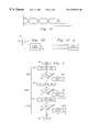
- FIG. 1illustrates a known memory bus channel having a parallel topology
- FIG. 2illustrates a block diagram of a computer system having means for implementing a continuity and integrity check of a memory bus channel having a serial topology according to one embodiment of the present disclosure
- FIG. 3illustrates a memory bus channel having a serial topology of the computer system of FIG. 1;
- FIGS. 4A, 4 B, and 4 Cillustrate an exemplary differential clock waveform, clock receiver, and clock generator for use with the computer system of FIG. 1, and
- FIG. 5is a flow diagram of the an exemplary continuity and integrity check of a memory bus channel having a serial topology according to one embodiment of the present disclosure.
- the computer system 20includes a central processing unit (CPU) 22 , input/output (I/O) devices, such as a display, a keyboard, a mouse, and associated controllers, collectively designated by a reference numeral 24 , a hard disk drive 26 , and other storage devices, such as a may include a floppy disk drive, CD-rom drive, and the like, collectively designated by a reference numeral 28 , various other subsystems, collectively designated by a reference numeral 30 , and a memory bus subsystem 50 having a serial topology, all interconnected via one or more buses, shown collectively in FIG. 2 as a bus 32 .
- Computer system 20further includes basic input output system (BIOS) 34 stored in memory, for example, a non-volatile flash memory that is a separate subsystem than the memory bus subsystem being tested, further as discussed herein.
- BIOSbasic input output system
- memory bus subsystem 50 of FIG. 1includes a RAMBUS channel.
- the present embodimentsmake use of sensing a source end 52 of the RAMBUS channel 50 to determine a continuity of the respective RAMBUS channel, i.e., to determine if the channel is contiguous.
- the RAMBUS specificationcalls out for termination pull-up resistors 54 on each signal line at a far or termination end 56 of the RAMBUS channel 50 , distal from a RAMBUS memory controller 58 .
- the present embodimentsinclude the use of weak pull-down resistors 60 on select signal lines at the source end 52 of the RAMBUS channel 50 , proximate the memory controller 58 .
- the voltage of a signal line at the source end 52will be pulled high.
- the voltage on the signal line at the source end 52will be low, which is indicative of a continuity failure.
- the voltage on each signal linecan be sensed and a failure reported if any low voltages are detected during a continuity and integrity check.
- the RAMBUS protocolincludes eighteen (18) data bits on data lines 64 .
- the eighteen data bits on data lines 64can be sensed directly from the RAMBUS memory controller.
- external latchesare included for use in sensing the voltage on the control lines 66 during a continuity and integrity check.
- the protocolincludes control lines 66 made up of five (5) column and three (3) row address strobes.
- EEPROM and CMOS configuration signals (not shown) of the RAMBUS channel subsystemare not sensed by the present embodiments, as corresponding signal connections for the same are made in parallel and thus not subject to being checked by the embodiments of the present disclosure.
- a clock generator 68provides a RAMBUS clock which starts at the termination end 56 of the channel 50 , goes to the source end 52 of the channel through the RAMBUS memory controller 58 , and then back out to the termination end 56 of the RAMBUS channel 50 .
- the memory controller 58is used with respect to the forward clock signal (ClockTM) on clock signal line 70 and a receiver 72 , placed on the returning clock signal line 74 at the termination end 56 of the channel, is used with respect to the returning clock signal (ClockFM).
- the forward clock signalClockTM
- a receiver 72placed on the returning clock signal line 74 at the termination end 56 of the channel
- Testing for continuity and integrity of a RAMBUS channelpreferably occurs each time the computer system is powered on.
- the RAMBUS in-line memory modules (RIMM) 76are disposed upon a motherboard (not shown) in suitable sockets and/or connectors 78 .
- RIMMRAMBUS in-line memory modules
- Testing of the integrity of the RAMBUS memory channel subsystem 50provides an indication of the computer system's operability.
- a computer systemmay be upgraded and/or be moved to different physical locations. In either case, it is also important to verify an integrity of the RAMBUS channel during the computer's product lifetime. It is highly likely that a computer user may perform an upgrade in the field. The computer user may also move the computer system from one physical location to another physical location.
- the computer systemis thus subject to becoming impaired through a failure in the RAMBUS channel (i.e., such as by contamination and/or faulty or loose socket connections).
- the present continuity and integrity check embodimentsare preferably initiated (implemented) when the computer system is powered on and there is an initialization of all the system memory.
- the RAMBUS channelPrior to initializing the memory, the RAMBUS channel is checked to verify that the RAMBUS channel is in tact (i.e., the channel has integrity).
- An error message appropriate for a given type of detected memory failurecould then be issued to a computer user. That is, there are different types of memory failures.
- a suitable error messagemay be issued upon detection of a given error condition. For instance, if it is determined that a RAMBUS channel does not exist where one should appear, then a message could be issued to the computer user indicating that a memory module may not be plugged in correctly.
- An error messagemight also indicate a specific line and potential remedy, for example, address bit four of the RAMBUS channel is not connected, please clean the contacts.
- the present embodimentsare particularly useful with respect to socket based RAMBUS channels.
- the present embodiments of checking an integrity and continuity of a RAMBUS channelare preferably incorporated into a computer system having a socket based RAMBUS channel subsystem.
- the RAMBUS channelmay also include an upgradeable channel and/or modular channel.
- the present embodimentsfurthermore detect a validity of input and output connections for each RIMM, along with respective conductive traces which connect the RIMMs together to form the RAMBUS channel.
- the main groups of signalsinclude data signals 64 , control signals 66 , and clock signals ( 70 , 74 ).
- Another group of signals of the RAMBUS channelincludes CMOS signals, which make up a small subset of the total RAMBUS channel signals and are routed in parallel. The CMOS signals are thus not subject to being verified with the embodiments of the present disclosure.
- the RAMBUS memory channel subsystemincludes a RAMBUS memory controller, socket/connector interfaces to each module, conductive traces on each module, a termination voltage, and a clock.
- a maximum level of integrity checkwould include an integrity check of all data, control, and clock lines.
- a reduced level of integrity checkcan include checking an integrity of any subset or combination of the data, control, and clock lines, less than all the data, control, and clock lines.
- a reduced level of integrity checkmay include checking an integrity of at least one of the following selected from the group consisting of a data line, a control line, and a clock line.
- the present embodimentsmay be characterized as including three levels of difficulty, each level of difficulty having corresponding implementation costs, to verify a continuity and integrity of the three different groups of data lines, control lines, and clock lines, respectively. Verifying a continuity of a data line is more readily accomplished than verifying a continuity and integrity of a clock line. Verification of continuity and integrity of a control line is intermediate the data line verification and the clock line verification.
- the voltage level of a data linecan be read by the RAMBUS memory controller.
- the channelincludes pull-up resistors coupled to a termination voltage.
- a weak pull-down resistoris placed in the RAMBUS channel at the source end proximate the controller.
- the voltage level at the weak pull-down resistorwill be read by the memory controller as a high level. If a high level is not detected by the memory controller, then the channel is determined to be non-contiguous for the data line, i.e., the channel lacks integrity.
- pull-down resistorsone each on a respective data line, the data lines of the RAMBUS channel can be sensed and an integrity thereof readily checked.
- the RAMBUS channelincludes eighteen data lines. During a continuity and integrity check, the data lines are readable by the RAMBUS memory controller.
- the RAMBUS memory controllercan operate in a prescribed manner for carrying out the reading of a level of any desired data line.
- the weak pull-down resistor (Rpull-down) 60preferably includes a resistor having a very high resistance, for example, in a range on the order of from 1 kOhms to 50 kOhms (or even 100 kOhms).
- the resistance of Rpull-downis high, so as to minimize any disturbance or adverse effects on the channel during a normal usage of the RAMBUS channel.
- the pull-up resistor 54can include a resistor (Rpull-up) having a low resistance, for example, on the order of 25 ohms to 50 ohms.
- the pull-up resistor, Rpull-upis on the order of 27 ohms.
- Rpull-updominates and pulls the respective line high at the source end of the channel. If the channel is not contiguous, then the line goes low at the source end of the channel with the use of the weak pull-down resistor.
- the Rpull-up resistance valueis preferably much less that the Rpull-down resistance value, for example, at least one order of magnitude less.
- each control line 66includes a pull-up resistor 54 , Rpull-up, coupled between a distal end of a control line and a termination voltage.
- Weak pull-down resistors 60are coupled between each control line 66 and ground potential at the source end 52 of the RAMBUS channel, proximate the memory controller 58 .
- the pull-up resistors 54 and weak pull-down resistors 60can include resistance values similar to those resistors associated with the data lines 64 .
- the memory controller 58can not read a state of the control lines 66 .
- the memory controllercan only write data out to the control lines.
- any suitable buffer, latch, or high input impedance device 80(hereafter referred to only as a buffer, for simplicity) is included or coupled to a respective control line, proximate the weak pull-down resistor 60 and the memory controller. Buffers, latches, and high input impedance devices are known in the art and thus not discussed in detail herein.
- the buffer 80enables the level present on a respective control line to be detected during a continuity and integrity check without causing any adverse loading of a respective control line during a normal usage of the channel.
- the bufferenables a signal on a respective control line to the detected and/or made readable by the computer system outside the RAMBUS controller.
- the RAMBUS channelincludes eight control lines, including, for example, address lines.
- Eight weak pull-down resistors and eight buffers (latches, or high input impedance devices)are used in the determining of a continuity and integrity of the RAMBUS channel control lines.
- Checking a continuity and integrity of the control linescan be carried out in a similar manner as that discussed above with respect to checking the continuity and integrity of the data lines, with the exception of reading the level or state of the control lines via a respective buffer.
- Any suitable device 82may be used for enabling a reading of the level information of a desired control line.
- a general purpose input output (GPIO) device 82may be used.
- the clock linesinclude a clock TM line 70 and a clock FM line 74 .
- the clock TM (clock to master) line 70is a clock line disposed between a clock generator 68 , through the RIMM modules 76 , and onto the RAMBUS memory controller 58 .
- the clock TM lineis further routed into and through the RAMBUS controller and exits as the clock FM (clock from master) line 74 .
- the clock FM line 74is disposed between the RAMBUS controller 58 , the RIMM modules 76 , and a pull-up resistor 54 coupled to a termination voltage 62 .
- the clock signalis used for providing prescribed clocking of the RIMM modules 76 .
- the clock generator 68provides a clock to master clock signal (ClockTM) through the RIMM modules to the RAMBUS memory controller.
- the clockis further routed from the RAMBUS memory controller, through the RIMM modules, to a pull-up resistor and termination voltage at the termination end of the RAMBUS channel as a clock from master clock signal (ClockFM).
- the RAMBUS memory controlleris controlled in a prescribed manner for detecting a validity of the ClockTM signal. In other words, the RAMBUS memory controller can be used for detecting a presence or absence of the ClockTM signal. In a preferred embodiment, no external level sensing means is included for sensing a level of the ClockTM line.
- the clock generatorincludes any clock generator known in the art for providing suitable clock signals for use with the RAMBUS memory channel subsystem.
- the clock generatormay include a differential clock, having positive and negative clock signals.
- FIG. 4Aillustrates exemplary differential clock signals, including positive and negative clock signals.
- the clock receiverincludes positive and negative ClockFM signal inputs and the clock generator of FIG. 4C provides positive and negative ClockTM signals.
- the clock receiver 72preferably includes a suitable high input impedance buffer and circuitry for detecting a presence or absence of the ClockFM signal.
- the clock receiverfurther includes any suitable detection circuitry which does not adversely affect the positive and negative clock lines, (e.g., skew) and which isolates the positive and negative clocks for further usage in the determination of a continuity and integrity of the RAMBUS channel ClockFM clock line.
- Each positive clock line and negative clock linehave a pull-up resistor attached thereto (only one shown in FIG. 3 for simplicity), the pull-up resistors further being coupled to a termination voltage.
- the clock receivermay include, for example, a buffered resistive-capacitive (RC) integrator having an output which is a function of a differential input, the output providing an indication of a presence or absence of the differential clock signal ClockFM.
- a GPIO portmay be provided for sensing the clock receiver output at the termination end of the RAMBUS channel.
- the RAMBUS memory channel subsystemcan be fully checked for continuity and integrity. Potential contamination may be isolated to one or two fingers of a RIMM socket or connector and the occurrence thereof can be readily determined with the present embodiments. If a clock line does not have continuity or integrity throughout the RAMBUS memory channel subsystem, the RAMBUS memory channel subsystem will not function.
- the present embodimentsprovide an efficient method for determining the continuity and integrity of the clock line.
- the present embodimentsovercome the visual inspection deficiencies of prior methods.
- the present embodimentsenable the detection and determination of which signal lines (data, control, or clock) of the RAMBUS memory channel subsystem are faulty and/or in need of correction.
- the present embodimentsfurthermore enable the detection of a fault in the memory subsystem to be readily detected, diagnosed, and provide guidance for its remedy.
- the present embodimentsthus enable the continuity and integrity checking of three independent sets of signal lines (data, control, and clock) in any given combination as desired for a particular RAMBUS channel application.
- Suitable program code stored in memorysuch as ROM, can be implemented via the computer system basic input output system (BIOS) firmware and the processor for carrying out a prescribed continuity and integrity check of the RAMBUS memory channel subsystem.
- BIOSbasic input output system
- the continuity and integrity check of the RAMBUS channelcan include checking of the data lines, control lines, and clock lines.
- the computer systemis powered on.
- step 92the data lines are tested.
- step 94an inquiry is made as to whether or not the data lines tested okay. If the data lines tested okay, then the process proceeds to step 96 .
- step 96the control lines are tested.
- step 98an inquiry is made as to whether or not the control lines tested okay. If the control lines tested okay, then the process proceeds to step 100 .
- the clock linesare tested.
- step 102an inquiry is made as to whether or not the clock lines tested okay. If the clock lines tested okay, then the continuity and integrity check of the RAMBUS channel is completed at step 104 . Returning to step 94 , if the data lines did not all test okay, then the process continues with step 106 . In step 106 , an appropriate notification is issued for signaling that the continuity and integrity check of the data lines failed. Subsequent to step 106 , the process ends at step 104 . Returning to step 98 , if the control lines did not all test okay, then the process continues with step 108 . In step 108 , an appropriate notification is issued for signaling that the continuity and integrity check of the control lines failed.
- step 108the process ends at step 104 .
- step 110an appropriate notification is issued for signaling that the continuity and integrity check of the clock lines failed.
- step 110the process ends at step 104 .
- the BIOSexecutes a boot-up routine.
- the boot-up routineis typically stored in ROM (as opposed to the memory subsystem).
- the boot-up routineincludes initializing the memory subsystem to insure that none of the memory chips are driving data (i.e., to insure that the memory chips are idle).
- the boot-up routinethen reads the data lines via the memory controller to insure that nothing is being read back from the memory subsystem.
- the data linesare all in a high state (i.e., logical “1”), then it indicates that all of the data lines are being pulled high on the RAMBUS channel by the respective pull-up resistors. The data line continuity and integrity is thus confirmed. In this instance, the weak pull-down resistors at the beginning of the channel were not needed. However, if seventeen “1's” are detected and one “0”, then it indicates that one of the data lines is not continuous all the way to the termination voltage. In addition, if all “0's” were detected, then none of the data lines is continuous all the way to the termination voltage.
- RIMM modulemay not be plugged in at all, since the probability of having all “0's” is typically very low.
- Different error reportsmay be issued depending upon a total number of “0's” (i.e., opens) detected. If the data line continuity and integrity test okay, then the process continues with a testing of a next set or sets of signal lines (e.g., control and/or clock). If a problem during data line continuity and integrity check was discovered, then the testing is stopped and an appropriate error signal and/or report is generated or issued.
- An error reportmay include a beep code, the illumination of an LED on a system board, or any other suitable visual or audio indication as may be desired for a particular RAMBUS channel continuity and integrity check application. Such an error report provides notification to a computer system operator or user that a problem exists in the data lines of the RAMBUS channel.
- control and clock linesare tested in a manner similar to that discussed above with respect to testing a continuity and integrity of the data lines.
- reading a state on a respective lineis accomplished with the use of a prescribed GPIO port, latch, buffer, or via the controller, whatever the case may be for the given control or clock line.
- the RAMBUS memory controllerhas an ability to read and write onto the data lines.
- the RAMBUS memory controllercan only write to the control lines, thus suitable buffers and GPIO ports are used for reading of the control lines.
- the presence or absence of the ClockFM clockcould be indicated by a high or low (e.g., “1” or “0”) at an output of the clock receiver.
- the presence or absence of the ClockTM clockcan be detected by the memory controller.
- the BIOS boot-up routineincludes suitable instructions for causing the processor to interact with and/or control the RAMBUS memory controller, in addition to the reading of select GPIO ports, latches, and buffers in a manner for carrying out a prescribed continuity and integrity check of the RAMBUS channel. Reading of any given RAMBUS channel signal line depends upon how the detection of a respective signal line is implemented.
- a continuity and integrity check routinemay further be included as part of a power on self test (POST) of the given computer system. Implementations other than those specifically discussed herein are possible.
- a continuity and integrity checkmay include only the data and control lines, but not the clock lines. Any combination and order of the data, control, and clock lines may be tested as desired for a particular continuity and integrity check.
Landscapes
- Engineering & Computer Science (AREA)
- General Engineering & Computer Science (AREA)
- Theoretical Computer Science (AREA)
- Computer Hardware Design (AREA)
- Quality & Reliability (AREA)
- Physics & Mathematics (AREA)
- General Physics & Mathematics (AREA)
- Techniques For Improving Reliability Of Storages (AREA)
Abstract
Description
Claims (23)
Priority Applications (1)
| Application Number | Priority Date | Filing Date | Title |
|---|---|---|---|
| US09/237,704US6357018B1 (en) | 1999-01-26 | 1999-01-26 | Method and apparatus for determining continuity and integrity of a RAMBUS channel in a computer system |
Applications Claiming Priority (1)
| Application Number | Priority Date | Filing Date | Title |
|---|---|---|---|
| US09/237,704US6357018B1 (en) | 1999-01-26 | 1999-01-26 | Method and apparatus for determining continuity and integrity of a RAMBUS channel in a computer system |
Publications (1)
| Publication Number | Publication Date |
|---|---|
| US6357018B1true US6357018B1 (en) | 2002-03-12 |
Family
ID=22894809
Family Applications (1)
| Application Number | Title | Priority Date | Filing Date |
|---|---|---|---|
| US09/237,704Expired - LifetimeUS6357018B1 (en) | 1999-01-26 | 1999-01-26 | Method and apparatus for determining continuity and integrity of a RAMBUS channel in a computer system |
Country Status (1)
| Country | Link |
|---|---|
| US (1) | US6357018B1 (en) |
Cited By (42)
| Publication number | Priority date | Publication date | Assignee | Title |
|---|---|---|---|---|
| US20030038639A1 (en)* | 1999-12-23 | 2003-02-27 | Dell Products L.P. | Data processing systems having mismatched impedance components |
| US6593801B1 (en) | 2002-06-07 | 2003-07-15 | Pericom Semiconductor Corp. | Power down mode signaled by differential transmitter's high-Z state detected by receiver sensing same voltage on differential lines |
| US6636943B1 (en)* | 1999-07-30 | 2003-10-21 | Hewlett-Packard Development Company, L.P. | Method for detecting continuity modules in a direct Rambus DRAM subsystem |
| US6690612B2 (en)* | 2000-10-30 | 2004-02-10 | Infineon Technologies Ag | Voltage supply for semiconductor memory |
| US6715014B1 (en)* | 2000-05-25 | 2004-03-30 | Hewlett-Packard Development Company, L.P. | Module array |
| US20050086420A1 (en)* | 2002-04-25 | 2005-04-21 | Wilcox Jeffrey R. | Low latency buffer control system and method |
| US20050254221A1 (en)* | 2000-05-10 | 2005-11-17 | Rambus Inc. | Clock routing in multiple channel modules and bus systems |
| US20060036826A1 (en)* | 2004-07-30 | 2006-02-16 | International Business Machines Corporation | System, method and storage medium for providing a bus speed multiplier |
| US20060095620A1 (en)* | 2004-10-29 | 2006-05-04 | International Business Machines Corporation | System, method and storage medium for merging bus data in a memory subsystem |
| US20060168422A1 (en)* | 2005-01-24 | 2006-07-27 | International Business Machines Corporation | System for indicating a plug position for a memory module in a memory system |
| US20060181942A1 (en)* | 2005-02-11 | 2006-08-17 | Cordero Edgar R | Switching a defective signal line with a spare signal line without shutting down the computer system |
| US20070276977A1 (en)* | 2006-05-24 | 2007-11-29 | International Business Machines Corporation | Systems and methods for providing memory modules with multiple hub devices |
| US20070286078A1 (en)* | 2005-11-28 | 2007-12-13 | International Business Machines Corporation | Method and system for providing frame start indication in a memory system having indeterminate read data latency |
| US20080016280A1 (en)* | 2004-10-29 | 2008-01-17 | International Business Machines Corporation | System, method and storage medium for providing data caching and data compression in a memory subsystem |
| US20080034148A1 (en)* | 2006-08-01 | 2008-02-07 | International Business Machines Corporation | Systems and methods for providing performance monitoring in a memory system |
| US20080040571A1 (en)* | 2004-10-29 | 2008-02-14 | International Business Machines Corporation | System, method and storage medium for bus calibration in a memory subsystem |
| US20080040562A1 (en)* | 2006-08-09 | 2008-02-14 | International Business Machines Corporation | Systems and methods for providing distributed autonomous power management in a memory system |
| US20080046795A1 (en)* | 2004-10-29 | 2008-02-21 | International Business Machines Corporation | System, method and storage medium for providing fault detection and correction in a memory subsystem |
| US20080065938A1 (en)* | 2004-10-29 | 2008-03-13 | International Business Machines Corporation | System, method and storage medium for testing a memory module |
| US20080133797A1 (en)* | 2004-07-30 | 2008-06-05 | International Business Machines Corporation | System, method and storage medium for a multi-mode memory buffer device |
| US20080177929A1 (en)* | 2004-10-29 | 2008-07-24 | International Business Machines Corporation | System, method and storage medium for a memory subsystem command interface |
| US20080183977A1 (en)* | 2007-01-29 | 2008-07-31 | International Business Machines Corporation | Systems and methods for providing a dynamic memory bank page policy |
| US7441060B2 (en) | 2004-10-29 | 2008-10-21 | International Business Machines Corporation | System, method and storage medium for providing a service interface to a memory system |
| US7475316B2 (en) | 2004-10-29 | 2009-01-06 | International Business Machines Corporation | System, method and storage medium for providing a high speed test interface to a memory subsystem |
| US7478259B2 (en) | 2005-10-31 | 2009-01-13 | International Business Machines Corporation | System, method and storage medium for deriving clocks in a memory system |
| US7477522B2 (en) | 2006-10-23 | 2009-01-13 | International Business Machines Corporation | High density high reliability memory module with a fault tolerant address and command bus |
| US7490217B2 (en) | 2006-08-15 | 2009-02-10 | International Business Machines Corporation | Design structure for selecting memory busses according to physical memory organization information stored in virtual address translation tables |
| US7512762B2 (en) | 2004-10-29 | 2009-03-31 | International Business Machines Corporation | System, method and storage medium for a memory subsystem with positional read data latency |
| US20090121743A1 (en)* | 2003-03-06 | 2009-05-14 | Zxtalk Assets, Llc | Digital Method and Device for Transmission with Reduced Crosstalk |
| US7539842B2 (en) | 2006-08-15 | 2009-05-26 | International Business Machines Corporation | Computer memory system for selecting memory buses according to physical memory organization information stored in virtual address translation tables |
| US7539800B2 (en) | 2004-07-30 | 2009-05-26 | International Business Machines Corporation | System, method and storage medium for providing segment level sparing |
| US7584336B2 (en) | 2006-06-08 | 2009-09-01 | International Business Machines Corporation | Systems and methods for providing data modification operations in memory subsystems |
| US7587559B2 (en) | 2006-08-10 | 2009-09-08 | International Business Machines Corporation | Systems and methods for memory module power management |
| US7594055B2 (en) | 2006-05-24 | 2009-09-22 | International Business Machines Corporation | Systems and methods for providing distributed technology independent memory controllers |
| US7603526B2 (en) | 2007-01-29 | 2009-10-13 | International Business Machines Corporation | Systems and methods for providing dynamic memory pre-fetch |
| US7636813B2 (en) | 2006-05-22 | 2009-12-22 | International Business Machines Corporation | Systems and methods for providing remote pre-fetch buffers |
| US7669086B2 (en) | 2006-08-02 | 2010-02-23 | International Business Machines Corporation | Systems and methods for providing collision detection in a memory system |
| US7721140B2 (en) | 2007-01-02 | 2010-05-18 | International Business Machines Corporation | Systems and methods for improving serviceability of a memory system |
| US7765368B2 (en) | 2004-07-30 | 2010-07-27 | International Business Machines Corporation | System, method and storage medium for providing a serialized memory interface with a bus repeater |
| US7788421B1 (en)* | 2008-01-24 | 2010-08-31 | Google Inc. | Detectable null memory for airflow baffling |
| US20100269012A1 (en)* | 2006-10-23 | 2010-10-21 | International Business Machines Corporation | High Density High Reliability Memory Module with Power Gating and a Fault Tolerant Address and Command Bus |
| US11422955B2 (en)* | 2016-07-04 | 2022-08-23 | Hewlett-Packard Development Company, L.P. | Electronic device |
Citations (18)
| Publication number | Priority date | Publication date | Assignee | Title |
|---|---|---|---|---|
| US5241643A (en) | 1990-06-19 | 1993-08-31 | Dell Usa, L.P. | Memory system and associated method for disabling address buffers connected to unused simm slots |
| US5254883A (en)* | 1992-04-22 | 1993-10-19 | Rambus, Inc. | Electrical current source circuitry for a bus |
| US5276895A (en) | 1986-09-18 | 1994-01-04 | Digital Equipment Corporation | Massively parallel array processing system |
| US5446696A (en)* | 1993-05-28 | 1995-08-29 | Rambus, Inc. | Method and apparatus for implementing refresh in a synchronous DRAM system |
| US5528553A (en) | 1993-10-01 | 1996-06-18 | Hal Computer Systems, Inc. | Method and apparatus for testing random access memory |
| US5537355A (en) | 1994-11-30 | 1996-07-16 | Sony Corporation Of Japan | Scheme to test/repair multiple large RAM blocks |
| US5578940A (en)* | 1995-04-04 | 1996-11-26 | Rambus, Inc. | Modular bus with single or double parallel termination |
| US5623620A (en) | 1993-06-30 | 1997-04-22 | Intel Corporation | Special test modes for a page buffer shared resource in a memory device |
| US5720031A (en) | 1995-12-04 | 1998-02-17 | Micron Technology, Inc. | Method and apparatus for testing memory devices and displaying results of such tests |
| US5794175A (en)* | 1997-09-09 | 1998-08-11 | Teradyne, Inc. | Low cost, highly parallel memory tester |
| US5818772A (en)* | 1996-11-26 | 1998-10-06 | Mitsubishi Denki Kabushiki Kaisha | Semiconductor memory devices having a built-in test function |
| US5862320A (en)* | 1995-12-22 | 1999-01-19 | Cirrus Logic, Inc. | SDRAM DIMM presence detect interface |
| US6003121A (en)* | 1998-05-18 | 1999-12-14 | Intel Corporation | Single and multiple channel memory detection and sizing |
| US6009541A (en)* | 1997-10-01 | 1999-12-28 | Micron Electronics, Inc. | Apparatus for performing an extensive diagnostic test in conjunction with a bios test routine |
| US6067594A (en)* | 1997-09-26 | 2000-05-23 | Rambus, Inc. | High frequency bus system |
| US6178532B1 (en)* | 1998-06-11 | 2001-01-23 | Micron Technology, Inc. | On-chip circuit and method for testing memory devices |
| US6198307B1 (en)* | 1998-10-26 | 2001-03-06 | Rambus Inc. | Output driver circuit with well-controlled output impedance |
| US6226729B1 (en)* | 1998-11-03 | 2001-05-01 | Intel Corporation | Method and apparatus for configuring and initializing a memory device and a memory channel |
- 1999
- 1999-01-26USUS09/237,704patent/US6357018B1/ennot_activeExpired - Lifetime
Patent Citations (18)
| Publication number | Priority date | Publication date | Assignee | Title |
|---|---|---|---|---|
| US5276895A (en) | 1986-09-18 | 1994-01-04 | Digital Equipment Corporation | Massively parallel array processing system |
| US5241643A (en) | 1990-06-19 | 1993-08-31 | Dell Usa, L.P. | Memory system and associated method for disabling address buffers connected to unused simm slots |
| US5254883A (en)* | 1992-04-22 | 1993-10-19 | Rambus, Inc. | Electrical current source circuitry for a bus |
| US5446696A (en)* | 1993-05-28 | 1995-08-29 | Rambus, Inc. | Method and apparatus for implementing refresh in a synchronous DRAM system |
| US5623620A (en) | 1993-06-30 | 1997-04-22 | Intel Corporation | Special test modes for a page buffer shared resource in a memory device |
| US5528553A (en) | 1993-10-01 | 1996-06-18 | Hal Computer Systems, Inc. | Method and apparatus for testing random access memory |
| US5537355A (en) | 1994-11-30 | 1996-07-16 | Sony Corporation Of Japan | Scheme to test/repair multiple large RAM blocks |
| US5578940A (en)* | 1995-04-04 | 1996-11-26 | Rambus, Inc. | Modular bus with single or double parallel termination |
| US5720031A (en) | 1995-12-04 | 1998-02-17 | Micron Technology, Inc. | Method and apparatus for testing memory devices and displaying results of such tests |
| US5862320A (en)* | 1995-12-22 | 1999-01-19 | Cirrus Logic, Inc. | SDRAM DIMM presence detect interface |
| US5818772A (en)* | 1996-11-26 | 1998-10-06 | Mitsubishi Denki Kabushiki Kaisha | Semiconductor memory devices having a built-in test function |
| US5794175A (en)* | 1997-09-09 | 1998-08-11 | Teradyne, Inc. | Low cost, highly parallel memory tester |
| US6067594A (en)* | 1997-09-26 | 2000-05-23 | Rambus, Inc. | High frequency bus system |
| US6009541A (en)* | 1997-10-01 | 1999-12-28 | Micron Electronics, Inc. | Apparatus for performing an extensive diagnostic test in conjunction with a bios test routine |
| US6003121A (en)* | 1998-05-18 | 1999-12-14 | Intel Corporation | Single and multiple channel memory detection and sizing |
| US6178532B1 (en)* | 1998-06-11 | 2001-01-23 | Micron Technology, Inc. | On-chip circuit and method for testing memory devices |
| US6198307B1 (en)* | 1998-10-26 | 2001-03-06 | Rambus Inc. | Output driver circuit with well-controlled output impedance |
| US6226729B1 (en)* | 1998-11-03 | 2001-05-01 | Intel Corporation | Method and apparatus for configuring and initializing a memory device and a memory channel |
Non-Patent Citations (3)
| Title |
|---|
| "Direct Rambus" Technology Disclosure, Oct. 15, 1997, 16 pages. |
| "Memory Latency Comparison" Rambus Inc., Sep. 6, 1996, 8 pages. |
| "Rambus Memory: Multi-Gigabytes/Second And Minimum System Cost" 4 pages. |
Cited By (81)
| Publication number | Priority date | Publication date | Assignee | Title |
|---|---|---|---|---|
| US6636943B1 (en)* | 1999-07-30 | 2003-10-21 | Hewlett-Packard Development Company, L.P. | Method for detecting continuity modules in a direct Rambus DRAM subsystem |
| US20030038639A1 (en)* | 1999-12-23 | 2003-02-27 | Dell Products L.P. | Data processing systems having mismatched impedance components |
| US6788073B2 (en) | 1999-12-23 | 2004-09-07 | Dell Products L.P. | Data processing systems having mismatched impedance components |
| US20050254221A1 (en)* | 2000-05-10 | 2005-11-17 | Rambus Inc. | Clock routing in multiple channel modules and bus systems |
| US8050042B2 (en)* | 2000-05-10 | 2011-11-01 | Rambus Inc. | Clock routing in multiple channel modules and bus systems and method for routing the same |
| US20070120575A1 (en)* | 2000-05-10 | 2007-05-31 | Rambus Inc. | Multiple Channel Modules and Bus Systems Using Same |
| US6715014B1 (en)* | 2000-05-25 | 2004-03-30 | Hewlett-Packard Development Company, L.P. | Module array |
| US6690612B2 (en)* | 2000-10-30 | 2004-02-10 | Infineon Technologies Ag | Voltage supply for semiconductor memory |
| US20050086420A1 (en)* | 2002-04-25 | 2005-04-21 | Wilcox Jeffrey R. | Low latency buffer control system and method |
| US6674319B1 (en) | 2002-06-07 | 2004-01-06 | Pericom Semiconductor Corp. | Power down mode signaled by differential transmitter's high-Z state detected by receiver sensing same voltage on differential lines |
| US6593801B1 (en) | 2002-06-07 | 2003-07-15 | Pericom Semiconductor Corp. | Power down mode signaled by differential transmitter's high-Z state detected by receiver sensing same voltage on differential lines |
| US7764083B2 (en)* | 2003-03-06 | 2010-07-27 | Frederic Broyde | Digital method and device for transmission with reduced crosstalk |
| US20090121743A1 (en)* | 2003-03-06 | 2009-05-14 | Zxtalk Assets, Llc | Digital Method and Device for Transmission with Reduced Crosstalk |
| US20060036826A1 (en)* | 2004-07-30 | 2006-02-16 | International Business Machines Corporation | System, method and storage medium for providing a bus speed multiplier |
| US20080133797A1 (en)* | 2004-07-30 | 2008-06-05 | International Business Machines Corporation | System, method and storage medium for a multi-mode memory buffer device |
| US7765368B2 (en) | 2004-07-30 | 2010-07-27 | International Business Machines Corporation | System, method and storage medium for providing a serialized memory interface with a bus repeater |
| US7539800B2 (en) | 2004-07-30 | 2009-05-26 | International Business Machines Corporation | System, method and storage medium for providing segment level sparing |
| US7539810B2 (en) | 2004-07-30 | 2009-05-26 | International Business Machines Corporation | System, method and storage medium for a multi-mode memory buffer device |
| US8296541B2 (en) | 2004-10-29 | 2012-10-23 | International Business Machines Corporation | Memory subsystem with positional read data latency |
| US8589769B2 (en) | 2004-10-29 | 2013-11-19 | International Business Machines Corporation | System, method and storage medium for providing fault detection and correction in a memory subsystem |
| US20060095620A1 (en)* | 2004-10-29 | 2006-05-04 | International Business Machines Corporation | System, method and storage medium for merging bus data in a memory subsystem |
| US7610423B2 (en) | 2004-10-29 | 2009-10-27 | International Business Machines Corporation | Service interface to a memory system |
| US20080046795A1 (en)* | 2004-10-29 | 2008-02-21 | International Business Machines Corporation | System, method and storage medium for providing fault detection and correction in a memory subsystem |
| US20080046796A1 (en)* | 2004-10-29 | 2008-02-21 | International Business Machines Corporation | System, method and storage medium for providing fault detection and correction in a memory subsystem |
| US20080065938A1 (en)* | 2004-10-29 | 2008-03-13 | International Business Machines Corporation | System, method and storage medium for testing a memory module |
| US7590882B2 (en) | 2004-10-29 | 2009-09-15 | International Business Machines Corporation | System, method and storage medium for bus calibration in a memory subsystem |
| US7844771B2 (en) | 2004-10-29 | 2010-11-30 | International Business Machines Corporation | System, method and storage medium for a memory subsystem command interface |
| US20080177929A1 (en)* | 2004-10-29 | 2008-07-24 | International Business Machines Corporation | System, method and storage medium for a memory subsystem command interface |
| US20090150636A1 (en)* | 2004-10-29 | 2009-06-11 | International Business Machines Corporation | Memory subsystem with positional read data latency |
| US8140942B2 (en) | 2004-10-29 | 2012-03-20 | International Business Machines Corporation | System, method and storage medium for providing fault detection and correction in a memory subsystem |
| US20080040571A1 (en)* | 2004-10-29 | 2008-02-14 | International Business Machines Corporation | System, method and storage medium for bus calibration in a memory subsystem |
| US7441060B2 (en) | 2004-10-29 | 2008-10-21 | International Business Machines Corporation | System, method and storage medium for providing a service interface to a memory system |
| US7451273B2 (en) | 2004-10-29 | 2008-11-11 | International Business Machines Corporation | System, method and storage medium for providing data caching and data compression in a memory subsystem |
| US20080313374A1 (en)* | 2004-10-29 | 2008-12-18 | International Business Machines Corporation | Service interface to a memory system |
| US7475316B2 (en) | 2004-10-29 | 2009-01-06 | International Business Machines Corporation | System, method and storage medium for providing a high speed test interface to a memory subsystem |
| US20080016280A1 (en)* | 2004-10-29 | 2008-01-17 | International Business Machines Corporation | System, method and storage medium for providing data caching and data compression in a memory subsystem |
| US7512762B2 (en) | 2004-10-29 | 2009-03-31 | International Business Machines Corporation | System, method and storage medium for a memory subsystem with positional read data latency |
| US7480759B2 (en) | 2004-10-29 | 2009-01-20 | International Business Machines Corporation | System, method and storage medium for providing data caching and data compression in a memory subsystem |
| US7480830B2 (en) | 2004-10-29 | 2009-01-20 | International Business Machines Corporation | System, method and storage medium for testing a memory module |
| US7484161B2 (en) | 2004-10-29 | 2009-01-27 | International Business Machines Corporation | System, method and storage medium for providing fault detection and correction in a memory subsystem |
| US7308527B2 (en)* | 2005-01-24 | 2007-12-11 | International Business Machines Corporation | System for indicating a plug position for a memory module in a memory system |
| US20080046650A1 (en)* | 2005-01-24 | 2008-02-21 | International Business Machines Corporation | System for indicating a plug position for a memory module in a memory system |
| US20060168422A1 (en)* | 2005-01-24 | 2006-07-27 | International Business Machines Corporation | System for indicating a plug position for a memory module in a memory system |
| US7441073B2 (en) | 2005-01-24 | 2008-10-21 | International Business Machines Corporation | System for indicating a plug position for a memory module in a memory system |
| US7793143B2 (en) | 2005-02-11 | 2010-09-07 | International Business Machines Corporation | Switching a defective signal line with a spare signal line without shutting down the computer system |
| US20060181942A1 (en)* | 2005-02-11 | 2006-08-17 | Cordero Edgar R | Switching a defective signal line with a spare signal line without shutting down the computer system |
| US7380161B2 (en)* | 2005-02-11 | 2008-05-27 | International Business Machines Corporation | Switching a defective signal line with a spare signal line without shutting down the computer system |
| US20080215929A1 (en)* | 2005-02-11 | 2008-09-04 | International Business Machines Corporation | Switching a defective signal line with a spare signal line without shutting down the computer system |
| US7934115B2 (en) | 2005-10-31 | 2011-04-26 | International Business Machines Corporation | Deriving clocks in a memory system |
| US7478259B2 (en) | 2005-10-31 | 2009-01-13 | International Business Machines Corporation | System, method and storage medium for deriving clocks in a memory system |
| US20090094476A1 (en)* | 2005-10-31 | 2009-04-09 | International Business Machines Corporation | Deriving clocks in a memory system |
| US8145868B2 (en) | 2005-11-28 | 2012-03-27 | International Business Machines Corporation | Method and system for providing frame start indication in a memory system having indeterminate read data latency |
| US8495328B2 (en) | 2005-11-28 | 2013-07-23 | International Business Machines Corporation | Providing frame start indication in a memory system having indeterminate read data latency |
| US20070286078A1 (en)* | 2005-11-28 | 2007-12-13 | International Business Machines Corporation | Method and system for providing frame start indication in a memory system having indeterminate read data latency |
| US7685392B2 (en) | 2005-11-28 | 2010-03-23 | International Business Machines Corporation | Providing indeterminate read data latency in a memory system |
| US8151042B2 (en) | 2005-11-28 | 2012-04-03 | International Business Machines Corporation | Method and system for providing identification tags in a memory system having indeterminate data response times |
| US8327105B2 (en) | 2005-11-28 | 2012-12-04 | International Business Machines Corporation | Providing frame start indication in a memory system having indeterminate read data latency |
| US7636813B2 (en) | 2006-05-22 | 2009-12-22 | International Business Machines Corporation | Systems and methods for providing remote pre-fetch buffers |
| US7640386B2 (en) | 2006-05-24 | 2009-12-29 | International Business Machines Corporation | Systems and methods for providing memory modules with multiple hub devices |
| US20070276977A1 (en)* | 2006-05-24 | 2007-11-29 | International Business Machines Corporation | Systems and methods for providing memory modules with multiple hub devices |
| US7594055B2 (en) | 2006-05-24 | 2009-09-22 | International Business Machines Corporation | Systems and methods for providing distributed technology independent memory controllers |
| US7584336B2 (en) | 2006-06-08 | 2009-09-01 | International Business Machines Corporation | Systems and methods for providing data modification operations in memory subsystems |
| US20080034148A1 (en)* | 2006-08-01 | 2008-02-07 | International Business Machines Corporation | Systems and methods for providing performance monitoring in a memory system |
| US7493439B2 (en) | 2006-08-01 | 2009-02-17 | International Business Machines Corporation | Systems and methods for providing performance monitoring in a memory system |
| US7669086B2 (en) | 2006-08-02 | 2010-02-23 | International Business Machines Corporation | Systems and methods for providing collision detection in a memory system |
| US20080040562A1 (en)* | 2006-08-09 | 2008-02-14 | International Business Machines Corporation | Systems and methods for providing distributed autonomous power management in a memory system |
| US7581073B2 (en) | 2006-08-09 | 2009-08-25 | International Business Machines Corporation | Systems and methods for providing distributed autonomous power management in a memory system |
| US7587559B2 (en) | 2006-08-10 | 2009-09-08 | International Business Machines Corporation | Systems and methods for memory module power management |
| US7539842B2 (en) | 2006-08-15 | 2009-05-26 | International Business Machines Corporation | Computer memory system for selecting memory buses according to physical memory organization information stored in virtual address translation tables |
| US7490217B2 (en) | 2006-08-15 | 2009-02-10 | International Business Machines Corporation | Design structure for selecting memory busses according to physical memory organization information stored in virtual address translation tables |
| US7636833B2 (en) | 2006-08-15 | 2009-12-22 | International Business Machines Corporation | Method for selecting memory busses according to physical memory organization information associated with virtual address translation tables |
| US7870459B2 (en) | 2006-10-23 | 2011-01-11 | International Business Machines Corporation | High density high reliability memory module with power gating and a fault tolerant address and command bus |
| US20100269012A1 (en)* | 2006-10-23 | 2010-10-21 | International Business Machines Corporation | High Density High Reliability Memory Module with Power Gating and a Fault Tolerant Address and Command Bus |
| US7477522B2 (en) | 2006-10-23 | 2009-01-13 | International Business Machines Corporation | High density high reliability memory module with a fault tolerant address and command bus |
| US8381064B2 (en) | 2006-10-23 | 2013-02-19 | International Business Machines Corporation | High density high reliability memory module with power gating and a fault tolerant address and command bus |
| US7721140B2 (en) | 2007-01-02 | 2010-05-18 | International Business Machines Corporation | Systems and methods for improving serviceability of a memory system |
| US20080183977A1 (en)* | 2007-01-29 | 2008-07-31 | International Business Machines Corporation | Systems and methods for providing a dynamic memory bank page policy |
| US7603526B2 (en) | 2007-01-29 | 2009-10-13 | International Business Machines Corporation | Systems and methods for providing dynamic memory pre-fetch |
| US7606988B2 (en) | 2007-01-29 | 2009-10-20 | International Business Machines Corporation | Systems and methods for providing a dynamic memory bank page policy |
| US7788421B1 (en)* | 2008-01-24 | 2010-08-31 | Google Inc. | Detectable null memory for airflow baffling |
| US11422955B2 (en)* | 2016-07-04 | 2022-08-23 | Hewlett-Packard Development Company, L.P. | Electronic device |
Similar Documents
| Publication | Publication Date | Title |
|---|---|---|
| US6357018B1 (en) | Method and apparatus for determining continuity and integrity of a RAMBUS channel in a computer system | |
| US6886116B1 (en) | Data storage system adapted to validate error detection logic used in such system | |
| US5959914A (en) | Memory controller with error correction memory test application | |
| US6055653A (en) | Method and apparatus for testing gang memory modules | |
| US6715101B2 (en) | Redundant controller data storage system having an on-line controller removal system and method | |
| US6708285B2 (en) | Redundant controller data storage system having system and method for handling controller resets | |
| US8074159B2 (en) | Method and apparatus for detecting communication errors on a bus | |
| US6223309B1 (en) | Method and apparatus for ECC logic test | |
| US20020133743A1 (en) | Redundant controller data storage system having hot insertion system and method | |
| US20030088805A1 (en) | Error indication in a raid memory system | |
| CN103531247B (en) | test device | |
| WO1997005539A2 (en) | Host adapter providing automatic terminator configuration | |
| JPS6321154B2 (en) | ||
| WO2014082275A1 (en) | Method and apparatus for detecting cable connection condition | |
| CN216748731U (en) | Detection circuit, interface link tooling plate and detection system | |
| CN107688521A (en) | A kind of server power supply detects circuit and detection method in place | |
| US20200132768A1 (en) | SAS Connector Conduction Detecting System And Method Thereof | |
| CN111176913A (en) | A circuit and method for detecting Cable Port in a server | |
| CN210666750U (en) | Memory fault alarm device | |
| US5436856A (en) | Self testing computer system with circuits including test registers | |
| US5881072A (en) | Method of detecting error correction devices on plug-compatible memory modules | |
| US11609832B2 (en) | System and method for hardware component connectivity verification | |
| CN112596983A (en) | A monitoring method for a connector in a server | |
| US20230333951A1 (en) | Hard disk indicator circuit and hard disk backplane | |
| US20090079456A1 (en) | Apparatus, system, and method for integrated component testing |
Legal Events
| Date | Code | Title | Description |
|---|---|---|---|
| AS | Assignment | Owner name:DELL USA, L.P., TEXAS Free format text:ASSIGNMENT OF ASSIGNORS INTEREST;ASSIGNORS:NELSON, AMY C.;STUEWE, JOHN;REEL/FRAME:009894/0957;SIGNING DATES FROM 19990412 TO 19990413 | |
| STCF | Information on status: patent grant | Free format text:PATENTED CASE | |
| FEPP | Fee payment procedure | Free format text:PAYOR NUMBER ASSIGNED (ORIGINAL EVENT CODE: ASPN); ENTITY STATUS OF PATENT OWNER: LARGE ENTITY | |
| FPAY | Fee payment | Year of fee payment:4 | |
| FPAY | Fee payment | Year of fee payment:8 | |
| FPAY | Fee payment | Year of fee payment:12 | |
| AS | Assignment | Owner name:BANK OF AMERICA, N.A., AS ADMINISTRATIVE AGENT, TE Free format text:PATENT SECURITY AGREEMENT (ABL);ASSIGNORS:DELL INC.;APPASSURE SOFTWARE, INC.;ASAP SOFTWARE EXPRESS, INC.;AND OTHERS;REEL/FRAME:031898/0001 Effective date:20131029 Owner name:BANK OF NEW YORK MELLON TRUST COMPANY, N.A., AS FIRST LIEN COLLATERAL AGENT, TEXAS Free format text:PATENT SECURITY AGREEMENT (NOTES);ASSIGNORS:APPASSURE SOFTWARE, INC.;ASAP SOFTWARE EXPRESS, INC.;BOOMI, INC.;AND OTHERS;REEL/FRAME:031897/0348 Effective date:20131029 Owner name:BANK OF AMERICA, N.A., AS COLLATERAL AGENT, NORTH CAROLINA Free format text:PATENT SECURITY AGREEMENT (TERM LOAN);ASSIGNORS:DELL INC.;APPASSURE SOFTWARE, INC.;ASAP SOFTWARE EXPRESS, INC.;AND OTHERS;REEL/FRAME:031899/0261 Effective date:20131029 Owner name:BANK OF AMERICA, N.A., AS ADMINISTRATIVE AGENT, TEXAS Free format text:PATENT SECURITY AGREEMENT (ABL);ASSIGNORS:DELL INC.;APPASSURE SOFTWARE, INC.;ASAP SOFTWARE EXPRESS, INC.;AND OTHERS;REEL/FRAME:031898/0001 Effective date:20131029 Owner name:BANK OF NEW YORK MELLON TRUST COMPANY, N.A., AS FI Free format text:PATENT SECURITY AGREEMENT (NOTES);ASSIGNORS:APPASSURE SOFTWARE, INC.;ASAP SOFTWARE EXPRESS, INC.;BOOMI, INC.;AND OTHERS;REEL/FRAME:031897/0348 Effective date:20131029 Owner name:BANK OF AMERICA, N.A., AS COLLATERAL AGENT, NORTH Free format text:PATENT SECURITY AGREEMENT (TERM LOAN);ASSIGNORS:DELL INC.;APPASSURE SOFTWARE, INC.;ASAP SOFTWARE EXPRESS, INC.;AND OTHERS;REEL/FRAME:031899/0261 Effective date:20131029 | |
| AS | Assignment | Owner name:DELL INC., TEXAS Free format text:RELEASE BY SECURED PARTY;ASSIGNOR:BANK OF AMERICA, N.A., AS ADMINISTRATIVE AGENT;REEL/FRAME:040065/0216 Effective date:20160907 Owner name:DELL MARKETING L.P., TEXAS Free format text:RELEASE BY SECURED PARTY;ASSIGNOR:BANK OF AMERICA, N.A., AS ADMINISTRATIVE AGENT;REEL/FRAME:040065/0216 Effective date:20160907 Owner name:COMPELLANT TECHNOLOGIES, INC., MINNESOTA Free format text:RELEASE BY SECURED PARTY;ASSIGNOR:BANK OF AMERICA, N.A., AS ADMINISTRATIVE AGENT;REEL/FRAME:040065/0216 Effective date:20160907 Owner name:DELL SOFTWARE INC., CALIFORNIA Free format text:RELEASE BY SECURED PARTY;ASSIGNOR:BANK OF AMERICA, N.A., AS ADMINISTRATIVE AGENT;REEL/FRAME:040065/0216 Effective date:20160907 Owner name:DELL PRODUCTS L.P., TEXAS Free format text:RELEASE BY SECURED PARTY;ASSIGNOR:BANK OF AMERICA, N.A., AS ADMINISTRATIVE AGENT;REEL/FRAME:040065/0216 Effective date:20160907 Owner name:DELL USA L.P., TEXAS Free format text:RELEASE BY SECURED PARTY;ASSIGNOR:BANK OF AMERICA, N.A., AS ADMINISTRATIVE AGENT;REEL/FRAME:040065/0216 Effective date:20160907 Owner name:PEROT SYSTEMS CORPORATION, TEXAS Free format text:RELEASE BY SECURED PARTY;ASSIGNOR:BANK OF AMERICA, N.A., AS ADMINISTRATIVE AGENT;REEL/FRAME:040065/0216 Effective date:20160907 Owner name:CREDANT TECHNOLOGIES, INC., TEXAS Free format text:RELEASE BY SECURED PARTY;ASSIGNOR:BANK OF AMERICA, N.A., AS ADMINISTRATIVE AGENT;REEL/FRAME:040065/0216 Effective date:20160907 Owner name:FORCE10 NETWORKS, INC., CALIFORNIA Free format text:RELEASE BY SECURED PARTY;ASSIGNOR:BANK OF AMERICA, N.A., AS ADMINISTRATIVE AGENT;REEL/FRAME:040065/0216 Effective date:20160907 Owner name:APPASSURE SOFTWARE, INC., VIRGINIA Free format text:RELEASE BY SECURED PARTY;ASSIGNOR:BANK OF AMERICA, N.A., AS ADMINISTRATIVE AGENT;REEL/FRAME:040065/0216 Effective date:20160907 Owner name:SECUREWORKS, INC., GEORGIA Free format text:RELEASE BY SECURED PARTY;ASSIGNOR:BANK OF AMERICA, N.A., AS ADMINISTRATIVE AGENT;REEL/FRAME:040065/0216 Effective date:20160907 Owner name:WYSE TECHNOLOGY L.L.C., CALIFORNIA Free format text:RELEASE BY SECURED PARTY;ASSIGNOR:BANK OF AMERICA, N.A., AS ADMINISTRATIVE AGENT;REEL/FRAME:040065/0216 Effective date:20160907 Owner name:ASAP SOFTWARE EXPRESS, INC., ILLINOIS Free format text:RELEASE BY SECURED PARTY;ASSIGNOR:BANK OF AMERICA, N.A., AS ADMINISTRATIVE AGENT;REEL/FRAME:040065/0216 Effective date:20160907 | |
| AS | Assignment | Owner name:DELL SOFTWARE INC., CALIFORNIA Free format text:RELEASE BY SECURED PARTY;ASSIGNOR:BANK OF AMERICA, N.A., AS COLLATERAL AGENT;REEL/FRAME:040040/0001 Effective date:20160907 Owner name:CREDANT TECHNOLOGIES, INC., TEXAS Free format text:RELEASE BY SECURED PARTY;ASSIGNOR:BANK OF AMERICA, N.A., AS COLLATERAL AGENT;REEL/FRAME:040040/0001 Effective date:20160907 Owner name:DELL PRODUCTS L.P., TEXAS Free format text:RELEASE BY SECURED PARTY;ASSIGNOR:BANK OF AMERICA, N.A., AS COLLATERAL AGENT;REEL/FRAME:040040/0001 Effective date:20160907 Owner name:DELL USA L.P., TEXAS Free format text:RELEASE BY SECURED PARTY;ASSIGNOR:BANK OF AMERICA, N.A., AS COLLATERAL AGENT;REEL/FRAME:040040/0001 Effective date:20160907 Owner name:ASAP SOFTWARE EXPRESS, INC., ILLINOIS Free format text:RELEASE BY SECURED PARTY;ASSIGNOR:BANK OF AMERICA, N.A., AS COLLATERAL AGENT;REEL/FRAME:040040/0001 Effective date:20160907 Owner name:DELL MARKETING L.P., TEXAS Free format text:RELEASE BY SECURED PARTY;ASSIGNOR:BANK OF AMERICA, N.A., AS COLLATERAL AGENT;REEL/FRAME:040040/0001 Effective date:20160907 Owner name:APPASSURE SOFTWARE, INC., VIRGINIA Free format text:RELEASE BY SECURED PARTY;ASSIGNOR:BANK OF AMERICA, N.A., AS COLLATERAL AGENT;REEL/FRAME:040040/0001 Effective date:20160907 Owner name:SECUREWORKS, INC., GEORGIA Free format text:RELEASE BY SECURED PARTY;ASSIGNOR:BANK OF AMERICA, N.A., AS COLLATERAL AGENT;REEL/FRAME:040040/0001 Effective date:20160907 Owner name:COMPELLENT TECHNOLOGIES, INC., MINNESOTA Free format text:RELEASE BY SECURED PARTY;ASSIGNOR:BANK OF AMERICA, N.A., AS COLLATERAL AGENT;REEL/FRAME:040040/0001 Effective date:20160907 Owner name:FORCE10 NETWORKS, INC., CALIFORNIA Free format text:RELEASE BY SECURED PARTY;ASSIGNOR:BANK OF AMERICA, N.A., AS COLLATERAL AGENT;REEL/FRAME:040040/0001 Effective date:20160907 Owner name:PEROT SYSTEMS CORPORATION, TEXAS Free format text:RELEASE BY SECURED PARTY;ASSIGNOR:BANK OF AMERICA, N.A., AS COLLATERAL AGENT;REEL/FRAME:040040/0001 Effective date:20160907 Owner name:DELL INC., TEXAS Free format text:RELEASE BY SECURED PARTY;ASSIGNOR:BANK OF AMERICA, N.A., AS COLLATERAL AGENT;REEL/FRAME:040040/0001 Effective date:20160907 Owner name:WYSE TECHNOLOGY L.L.C., CALIFORNIA Free format text:RELEASE BY SECURED PARTY;ASSIGNOR:BANK OF AMERICA, N.A., AS COLLATERAL AGENT;REEL/FRAME:040040/0001 Effective date:20160907 Owner name:DELL USA L.P., TEXAS Free format text:RELEASE BY SECURED PARTY;ASSIGNOR:BANK OF NEW YORK MELLON TRUST COMPANY, N.A., AS COLLATERAL AGENT;REEL/FRAME:040065/0618 Effective date:20160907 Owner name:APPASSURE SOFTWARE, INC., VIRGINIA Free format text:RELEASE BY SECURED PARTY;ASSIGNOR:BANK OF NEW YORK MELLON TRUST COMPANY, N.A., AS COLLATERAL AGENT;REEL/FRAME:040065/0618 Effective date:20160907 Owner name:COMPELLENT TECHNOLOGIES, INC., MINNESOTA Free format text:RELEASE BY SECURED PARTY;ASSIGNOR:BANK OF NEW YORK MELLON TRUST COMPANY, N.A., AS COLLATERAL AGENT;REEL/FRAME:040065/0618 Effective date:20160907 Owner name:WYSE TECHNOLOGY L.L.C., CALIFORNIA Free format text:RELEASE BY SECURED PARTY;ASSIGNOR:BANK OF NEW YORK MELLON TRUST COMPANY, N.A., AS COLLATERAL AGENT;REEL/FRAME:040065/0618 Effective date:20160907 Owner name:DELL SOFTWARE INC., CALIFORNIA Free format text:RELEASE BY SECURED PARTY;ASSIGNOR:BANK OF NEW YORK MELLON TRUST COMPANY, N.A., AS COLLATERAL AGENT;REEL/FRAME:040065/0618 Effective date:20160907 Owner name:ASAP SOFTWARE EXPRESS, INC., ILLINOIS Free format text:RELEASE BY SECURED PARTY;ASSIGNOR:BANK OF NEW YORK MELLON TRUST COMPANY, N.A., AS COLLATERAL AGENT;REEL/FRAME:040065/0618 Effective date:20160907 Owner name:DELL PRODUCTS L.P., TEXAS Free format text:RELEASE BY SECURED PARTY;ASSIGNOR:BANK OF NEW YORK MELLON TRUST COMPANY, N.A., AS COLLATERAL AGENT;REEL/FRAME:040065/0618 Effective date:20160907 Owner name:DELL INC., TEXAS Free format text:RELEASE BY SECURED PARTY;ASSIGNOR:BANK OF NEW YORK MELLON TRUST COMPANY, N.A., AS COLLATERAL AGENT;REEL/FRAME:040065/0618 Effective date:20160907 Owner name:SECUREWORKS, INC., GEORGIA Free format text:RELEASE BY SECURED PARTY;ASSIGNOR:BANK OF NEW YORK MELLON TRUST COMPANY, N.A., AS COLLATERAL AGENT;REEL/FRAME:040065/0618 Effective date:20160907 Owner name:FORCE10 NETWORKS, INC., CALIFORNIA Free format text:RELEASE BY SECURED PARTY;ASSIGNOR:BANK OF NEW YORK MELLON TRUST COMPANY, N.A., AS COLLATERAL AGENT;REEL/FRAME:040065/0618 Effective date:20160907 Owner name:CREDANT TECHNOLOGIES, INC., TEXAS Free format text:RELEASE BY SECURED PARTY;ASSIGNOR:BANK OF NEW YORK MELLON TRUST COMPANY, N.A., AS COLLATERAL AGENT;REEL/FRAME:040065/0618 Effective date:20160907 Owner name:DELL MARKETING L.P., TEXAS Free format text:RELEASE BY SECURED PARTY;ASSIGNOR:BANK OF NEW YORK MELLON TRUST COMPANY, N.A., AS COLLATERAL AGENT;REEL/FRAME:040065/0618 Effective date:20160907 Owner name:PEROT SYSTEMS CORPORATION, TEXAS Free format text:RELEASE BY SECURED PARTY;ASSIGNOR:BANK OF NEW YORK MELLON TRUST COMPANY, N.A., AS COLLATERAL AGENT;REEL/FRAME:040065/0618 Effective date:20160907 | |
| AS | Assignment | Owner name:THE BANK OF NEW YORK MELLON TRUST COMPANY, N.A., AS NOTES COLLATERAL AGENT, TEXAS Free format text:SECURITY AGREEMENT;ASSIGNORS:ASAP SOFTWARE EXPRESS, INC.;AVENTAIL LLC;CREDANT TECHNOLOGIES, INC.;AND OTHERS;REEL/FRAME:040136/0001 Effective date:20160907 Owner name:CREDIT SUISSE AG, CAYMAN ISLANDS BRANCH, AS COLLATERAL AGENT, NORTH CAROLINA Free format text:SECURITY AGREEMENT;ASSIGNORS:ASAP SOFTWARE EXPRESS, INC.;AVENTAIL LLC;CREDANT TECHNOLOGIES, INC.;AND OTHERS;REEL/FRAME:040134/0001 Effective date:20160907 Owner name:CREDIT SUISSE AG, CAYMAN ISLANDS BRANCH, AS COLLAT Free format text:SECURITY AGREEMENT;ASSIGNORS:ASAP SOFTWARE EXPRESS, INC.;AVENTAIL LLC;CREDANT TECHNOLOGIES, INC.;AND OTHERS;REEL/FRAME:040134/0001 Effective date:20160907 Owner name:THE BANK OF NEW YORK MELLON TRUST COMPANY, N.A., A Free format text:SECURITY AGREEMENT;ASSIGNORS:ASAP SOFTWARE EXPRESS, INC.;AVENTAIL LLC;CREDANT TECHNOLOGIES, INC.;AND OTHERS;REEL/FRAME:040136/0001 Effective date:20160907 | |
| AS | Assignment | Owner name:WYSE TECHNOLOGY L.L.C., CALIFORNIA Free format text:RELEASE BY SECURED PARTY;ASSIGNOR:CREDIT SUISSE AG, CAYMAN ISLANDS BRANCH;REEL/FRAME:058216/0001 Effective date:20211101 Owner name:SCALEIO LLC, MASSACHUSETTS Free format text:RELEASE BY SECURED PARTY;ASSIGNOR:CREDIT SUISSE AG, CAYMAN ISLANDS BRANCH;REEL/FRAME:058216/0001 Effective date:20211101 Owner name:MOZY, INC., WASHINGTON Free format text:RELEASE BY SECURED PARTY;ASSIGNOR:CREDIT SUISSE AG, CAYMAN ISLANDS BRANCH;REEL/FRAME:058216/0001 Effective date:20211101 Owner name:MAGINATICS LLC, CALIFORNIA Free format text:RELEASE BY SECURED PARTY;ASSIGNOR:CREDIT SUISSE AG, CAYMAN ISLANDS BRANCH;REEL/FRAME:058216/0001 Effective date:20211101 Owner name:FORCE10 NETWORKS, INC., CALIFORNIA Free format text:RELEASE BY SECURED PARTY;ASSIGNOR:CREDIT SUISSE AG, CAYMAN ISLANDS BRANCH;REEL/FRAME:058216/0001 Effective date:20211101 Owner name:EMC IP HOLDING COMPANY LLC, TEXAS Free format text:RELEASE BY SECURED PARTY;ASSIGNOR:CREDIT SUISSE AG, CAYMAN ISLANDS BRANCH;REEL/FRAME:058216/0001 Effective date:20211101 Owner name:EMC CORPORATION, MASSACHUSETTS Free format text:RELEASE BY SECURED PARTY;ASSIGNOR:CREDIT SUISSE AG, CAYMAN ISLANDS BRANCH;REEL/FRAME:058216/0001 Effective date:20211101 Owner name:DELL SYSTEMS CORPORATION, TEXAS Free format text:RELEASE BY SECURED PARTY;ASSIGNOR:CREDIT SUISSE AG, CAYMAN ISLANDS BRANCH;REEL/FRAME:058216/0001 Effective date:20211101 Owner name:DELL SOFTWARE INC., CALIFORNIA Free format text:RELEASE BY SECURED PARTY;ASSIGNOR:CREDIT SUISSE AG, CAYMAN ISLANDS BRANCH;REEL/FRAME:058216/0001 Effective date:20211101 Owner name:DELL PRODUCTS L.P., TEXAS Free format text:RELEASE BY SECURED PARTY;ASSIGNOR:CREDIT SUISSE AG, CAYMAN ISLANDS BRANCH;REEL/FRAME:058216/0001 Effective date:20211101 Owner name:DELL MARKETING L.P., TEXAS Free format text:RELEASE BY SECURED PARTY;ASSIGNOR:CREDIT SUISSE AG, CAYMAN ISLANDS BRANCH;REEL/FRAME:058216/0001 Effective date:20211101 Owner name:DELL INTERNATIONAL, L.L.C., TEXAS Free format text:RELEASE BY SECURED PARTY;ASSIGNOR:CREDIT SUISSE AG, CAYMAN ISLANDS BRANCH;REEL/FRAME:058216/0001 Effective date:20211101 Owner name:DELL USA L.P., TEXAS Free format text:RELEASE BY SECURED PARTY;ASSIGNOR:CREDIT SUISSE AG, CAYMAN ISLANDS BRANCH;REEL/FRAME:058216/0001 Effective date:20211101 Owner name:CREDANT TECHNOLOGIES, INC., TEXAS Free format text:RELEASE BY SECURED PARTY;ASSIGNOR:CREDIT SUISSE AG, CAYMAN ISLANDS BRANCH;REEL/FRAME:058216/0001 Effective date:20211101 Owner name:AVENTAIL LLC, CALIFORNIA Free format text:RELEASE BY SECURED PARTY;ASSIGNOR:CREDIT SUISSE AG, CAYMAN ISLANDS BRANCH;REEL/FRAME:058216/0001 Effective date:20211101 Owner name:ASAP SOFTWARE EXPRESS, INC., ILLINOIS Free format text:RELEASE BY SECURED PARTY;ASSIGNOR:CREDIT SUISSE AG, CAYMAN ISLANDS BRANCH;REEL/FRAME:058216/0001 Effective date:20211101 | |
| AS | Assignment | Owner name:SCALEIO LLC, MASSACHUSETTS Free format text:RELEASE OF SECURITY INTEREST IN PATENTS PREVIOUSLY RECORDED AT REEL/FRAME (040136/0001);ASSIGNOR:THE BANK OF NEW YORK MELLON TRUST COMPANY, N.A., AS NOTES COLLATERAL AGENT;REEL/FRAME:061324/0001 Effective date:20220329 Owner name:EMC IP HOLDING COMPANY LLC (ON BEHALF OF ITSELF AND AS SUCCESSOR-IN-INTEREST TO MOZY, INC.), TEXAS Free format text:RELEASE OF SECURITY INTEREST IN PATENTS PREVIOUSLY RECORDED AT REEL/FRAME (040136/0001);ASSIGNOR:THE BANK OF NEW YORK MELLON TRUST COMPANY, N.A., AS NOTES COLLATERAL AGENT;REEL/FRAME:061324/0001 Effective date:20220329 Owner name:EMC CORPORATION (ON BEHALF OF ITSELF AND AS SUCCESSOR-IN-INTEREST TO MAGINATICS LLC), MASSACHUSETTS Free format text:RELEASE OF SECURITY INTEREST IN PATENTS PREVIOUSLY RECORDED AT REEL/FRAME (040136/0001);ASSIGNOR:THE BANK OF NEW YORK MELLON TRUST COMPANY, N.A., AS NOTES COLLATERAL AGENT;REEL/FRAME:061324/0001 Effective date:20220329 Owner name:DELL MARKETING CORPORATION (SUCCESSOR-IN-INTEREST TO FORCE10 NETWORKS, INC. AND WYSE TECHNOLOGY L.L.C.), TEXAS Free format text:RELEASE OF SECURITY INTEREST IN PATENTS PREVIOUSLY RECORDED AT REEL/FRAME (040136/0001);ASSIGNOR:THE BANK OF NEW YORK MELLON TRUST COMPANY, N.A., AS NOTES COLLATERAL AGENT;REEL/FRAME:061324/0001 Effective date:20220329 Owner name:DELL PRODUCTS L.P., TEXAS Free format text:RELEASE OF SECURITY INTEREST IN PATENTS PREVIOUSLY RECORDED AT REEL/FRAME (040136/0001);ASSIGNOR:THE BANK OF NEW YORK MELLON TRUST COMPANY, N.A., AS NOTES COLLATERAL AGENT;REEL/FRAME:061324/0001 Effective date:20220329 Owner name:DELL INTERNATIONAL L.L.C., TEXAS Free format text:RELEASE OF SECURITY INTEREST IN PATENTS PREVIOUSLY RECORDED AT REEL/FRAME (040136/0001);ASSIGNOR:THE BANK OF NEW YORK MELLON TRUST COMPANY, N.A., AS NOTES COLLATERAL AGENT;REEL/FRAME:061324/0001 Effective date:20220329 Owner name:DELL USA L.P., TEXAS Free format text:RELEASE OF SECURITY INTEREST IN PATENTS PREVIOUSLY RECORDED AT REEL/FRAME (040136/0001);ASSIGNOR:THE BANK OF NEW YORK MELLON TRUST COMPANY, N.A., AS NOTES COLLATERAL AGENT;REEL/FRAME:061324/0001 Effective date:20220329 Owner name:DELL MARKETING L.P. (ON BEHALF OF ITSELF AND AS SUCCESSOR-IN-INTEREST TO CREDANT TECHNOLOGIES, INC.), TEXAS Free format text:RELEASE OF SECURITY INTEREST IN PATENTS PREVIOUSLY RECORDED AT REEL/FRAME (040136/0001);ASSIGNOR:THE BANK OF NEW YORK MELLON TRUST COMPANY, N.A., AS NOTES COLLATERAL AGENT;REEL/FRAME:061324/0001 Effective date:20220329 Owner name:DELL MARKETING CORPORATION (SUCCESSOR-IN-INTEREST TO ASAP SOFTWARE EXPRESS, INC.), TEXAS Free format text:RELEASE OF SECURITY INTEREST IN PATENTS PREVIOUSLY RECORDED AT REEL/FRAME (040136/0001);ASSIGNOR:THE BANK OF NEW YORK MELLON TRUST COMPANY, N.A., AS NOTES COLLATERAL AGENT;REEL/FRAME:061324/0001 Effective date:20220329 | |
| AS | Assignment | Owner name:SCALEIO LLC, MASSACHUSETTS Free format text:RELEASE OF SECURITY INTEREST IN PATENTS PREVIOUSLY RECORDED AT REEL/FRAME (045455/0001);ASSIGNOR:THE BANK OF NEW YORK MELLON TRUST COMPANY, N.A., AS NOTES COLLATERAL AGENT;REEL/FRAME:061753/0001 Effective date:20220329 Owner name:EMC IP HOLDING COMPANY LLC (ON BEHALF OF ITSELF AND AS SUCCESSOR-IN-INTEREST TO MOZY, INC.), TEXAS Free format text:RELEASE OF SECURITY INTEREST IN PATENTS PREVIOUSLY RECORDED AT REEL/FRAME (045455/0001);ASSIGNOR:THE BANK OF NEW YORK MELLON TRUST COMPANY, N.A., AS NOTES COLLATERAL AGENT;REEL/FRAME:061753/0001 Effective date:20220329 Owner name:EMC CORPORATION (ON BEHALF OF ITSELF AND AS SUCCESSOR-IN-INTEREST TO MAGINATICS LLC), MASSACHUSETTS Free format text:RELEASE OF SECURITY INTEREST IN PATENTS PREVIOUSLY RECORDED AT REEL/FRAME (045455/0001);ASSIGNOR:THE BANK OF NEW YORK MELLON TRUST COMPANY, N.A., AS NOTES COLLATERAL AGENT;REEL/FRAME:061753/0001 Effective date:20220329 Owner name:DELL MARKETING CORPORATION (SUCCESSOR-IN-INTEREST TO FORCE10 NETWORKS, INC. AND WYSE TECHNOLOGY L.L.C.), TEXAS Free format text:RELEASE OF SECURITY INTEREST IN PATENTS PREVIOUSLY RECORDED AT REEL/FRAME (045455/0001);ASSIGNOR:THE BANK OF NEW YORK MELLON TRUST COMPANY, N.A., AS NOTES COLLATERAL AGENT;REEL/FRAME:061753/0001 Effective date:20220329 Owner name:DELL PRODUCTS L.P., TEXAS Free format text:RELEASE OF SECURITY INTEREST IN PATENTS PREVIOUSLY RECORDED AT REEL/FRAME (045455/0001);ASSIGNOR:THE BANK OF NEW YORK MELLON TRUST COMPANY, N.A., AS NOTES COLLATERAL AGENT;REEL/FRAME:061753/0001 Effective date:20220329 Owner name:DELL INTERNATIONAL L.L.C., TEXAS Free format text:RELEASE OF SECURITY INTEREST IN PATENTS PREVIOUSLY RECORDED AT REEL/FRAME (045455/0001);ASSIGNOR:THE BANK OF NEW YORK MELLON TRUST COMPANY, N.A., AS NOTES COLLATERAL AGENT;REEL/FRAME:061753/0001 Effective date:20220329 Owner name:DELL USA L.P., TEXAS Free format text:RELEASE OF SECURITY INTEREST IN PATENTS PREVIOUSLY RECORDED AT REEL/FRAME (045455/0001);ASSIGNOR:THE BANK OF NEW YORK MELLON TRUST COMPANY, N.A., AS NOTES COLLATERAL AGENT;REEL/FRAME:061753/0001 Effective date:20220329 Owner name:DELL MARKETING L.P. (ON BEHALF OF ITSELF AND AS SUCCESSOR-IN-INTEREST TO CREDANT TECHNOLOGIES, INC.), TEXAS Free format text:RELEASE OF SECURITY INTEREST IN PATENTS PREVIOUSLY RECORDED AT REEL/FRAME (045455/0001);ASSIGNOR:THE BANK OF NEW YORK MELLON TRUST COMPANY, N.A., AS NOTES COLLATERAL AGENT;REEL/FRAME:061753/0001 Effective date:20220329 Owner name:DELL MARKETING CORPORATION (SUCCESSOR-IN-INTEREST TO ASAP SOFTWARE EXPRESS, INC.), TEXAS Free format text:RELEASE OF SECURITY INTEREST IN PATENTS PREVIOUSLY RECORDED AT REEL/FRAME (045455/0001);ASSIGNOR:THE BANK OF NEW YORK MELLON TRUST COMPANY, N.A., AS NOTES COLLATERAL AGENT;REEL/FRAME:061753/0001 Effective date:20220329 |