US6356851B1 - Accelerated calibration for electronic compass module - Google Patents
Accelerated calibration for electronic compass moduleDownload PDFInfo
- Publication number
- US6356851B1 US6356851B1US09/245,260US24526099AUS6356851B1US 6356851 B1US6356851 B1US 6356851B1US 24526099 AUS24526099 AUS 24526099AUS 6356851 B1US6356851 B1US 6356851B1
- Authority
- US
- United States
- Prior art keywords
- changes
- vehicle
- sensors
- locus
- box
- Prior art date
- Legal status (The legal status is an assumption and is not a legal conclusion. Google has not performed a legal analysis and makes no representation as to the accuracy of the status listed.)
- Expired - Lifetime
Links
- 238000005070samplingMethods0.000claimsabstractdescription13
- 230000003466anti-cipated effectEffects0.000claimsabstractdescription10
- 238000000034methodMethods0.000claimsdescription14
- 230000000694effectsEffects0.000claims2
- 230000003472neutralizing effectEffects0.000claims2
- 238000004891communicationMethods0.000description4
- 238000005259measurementMethods0.000description4
- 238000010586diagramMethods0.000description3
- 238000005094computer simulationMethods0.000description1
- 238000012937correctionMethods0.000description1
- 238000011161developmentMethods0.000description1
- 239000004973liquid crystal related substanceSubstances0.000description1
- 238000004519manufacturing processMethods0.000description1
- 238000012986modificationMethods0.000description1
- 230000004048modificationEffects0.000description1
- 238000011160researchMethods0.000description1
- 230000035945sensitivityEffects0.000description1
- 239000007787solidSubstances0.000description1
- 238000012360testing methodMethods0.000description1
Images


Classifications
- G—PHYSICS
- G01—MEASURING; TESTING
- G01C—MEASURING DISTANCES, LEVELS OR BEARINGS; SURVEYING; NAVIGATION; GYROSCOPIC INSTRUMENTS; PHOTOGRAMMETRY OR VIDEOGRAMMETRY
- G01C17/00—Compasses; Devices for ascertaining true or magnetic north for navigation or surveying purposes
- G01C17/38—Testing, calibrating, or compensating of compasses
Definitions
- the present inventionrelates to electronic compasses of the type mounted on a dash or headliner of a vehicle for providing a continuous readout of the vehicle heading during operation.
- the known technique for recalibrating a compassrequires that the car be driven in the four cardinal directions (i.e., N, E, S, W) in sequence and at a fixed or constant rate before a complete set of corrections can be applied.
- the present inventionprovides accelerated calibration of an electronic compass for vehicle of the type employing magnetoresistive sensors.
- the systemmay be activated by a user operated panel switch or by a condition developing with a known slow automatic calibration routine in the event that the system detects that it has been forced into an unrecoverable state.
- the accelerated calibration technique of the present inventiondoes not require the driver to drive in any set pattern such as a circle: it only requires that the four cardinal headings be visited at least once.
- the accelerated or fast automatic calibration technique of the present inventiondetects and records high and low peaks in the output of the magnetoresistive sensors detecting respectively Forward and Lateral variations in the combination of remnant and Earth magnetic fields over time.
- the technique of the present inventioneliminates the need for the vehicle to be driven in the four cardinal directions in sequence and at a constant rate in order to complete the compass model in the computer.
- the technique of the present inventionis initiated when it is determined that the vehicle has been driven in an arc sufficient to generate a minimum threshold change in the output of both the Lateral and the Forward magnetoresistive sensors, whereupon the system models an arc and computes the center of curvature as the center of the locus in order that the current quadrant can be determined.
- a “box”is then calculated with the computed center computed for determining the four quadrants as contrasted with cardinal headings.
- the “box”is updated with each sampling and when the vehicle has, over time, been driven in all quadrants, the model is complete.
- the “box”will always contain the circle of the peaks of the sensor outputs from all four cardinal directions.
- the mapped circleis then shifted to be located within the limits of the outputs of the system amplifiers such that saturation is avoided; the compass readings detected are thus valid for determining headings and are not unduly influenced by the remnant magnetic fields.
- FIG. 1is a block diagram of the compass module of the present invention
- FIG. 2is a calibration state diagram for the system of FIG. 1;
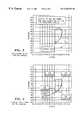
- FIG. 3is a plot of the locus of the initial readings of the Forward and Lateral magnetoresistive sensors
- FIG. 4is a plot of the sensor output coordinates for the vehicle traveling in an arc
- FIG. 5is a plot of the sensor output coordinates having the locus of the model coordinates superposed thereon;
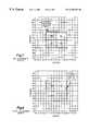
- FIG. 6is a view similar to FIG. 5 showing the locus divided into quadrants
- FIG. 7is a view similar to FIG. 6 illustrating the locus of the sensor output coordinates after the vehicle has traversed at least two quadrants;
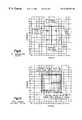
- FIG. 8is a view similar to FIG. 7 illustrating the locus of the sensor output coordinates after the vehicle has traversed headings in at least three quadrants;
- FIG. 9is a view similar to FIG. 8 illustrating a plot of the sensor output coordinates after the vehicle has traversed a path including the four cardinal directions;
- FIG. 10is a view similar to FIG. 9 showing the computer model of the locus of the compass coordinates superposed thereon for determining that the model is valid.
- the system or module of the present inventionis indicated generally at 10 and has a microprocessor or microcontroller 12 which includes an analog to digital converter 14 which receives output signals from a Forward output amplifier 16 and a Lateral output amplifier 18 along lines 20 , 22 respectively.
- the microcontroller 12provides inputs to the gain control section 24 , the Forward and Lateral offset control section 26 and the set/reset section 28 respectively along lines 30 , 32 , 34 .
- the gain control 24 , the offset control 26 and the set/reset 28provide inputs to the Forward and Lateral magnetoresistive (MR) sensors in section 36 respectively along lines 38 , 40 , 42 .
- the MR sensor section 36provides separate inputs to the Forward output amplifier 16 and Lateral output amplifier 18 along lines 44 , 46 , respectively, for providing the directional response to movement of the vehicle with respect to the earth's magnetic field.
- the microprocessor section 12 , operating mode and display characteristicsare controlled by a user-actuated switch section 48 ; the A/D converter section 14 provides an output along line 50 to the display driver section 52 which provides outputs to the display grid driver 54 along line 53 and along line 55 to the display unit 56 , which receives an output also from the display grid driver along line 58 .
- the systemalso includes a power supply comprising section 60 , which provides the low voltage direct current power to the various sections of the system 10 .
- the microprocessor section 12also provides an output to and receives inputs from a communication bus interface section 62 along line 64 .
- the communication bus interface section 62is adapted for connection to the vehicle bus along line 66 .
- the switch section 48includes user operated manual switches 72 and 74 which provide inputs to the microprocessor along lines 68 , 70 .
- Switch 74is typically a selector switch for user-desired selection of the display mode (i.e., in either English or metric units); whereas, switch 72 is a user input for requesting accelerated calibration for the system.
- the Forward and Lateral magnetic sensorsrespectively are typically solid state devices containing magnetoresistive strips arranged as a Wheatstone bridge currently obtainable from Phillips Electronics, Donnelly Corp. and Honeywell Electronics. It will be understood by those skilled in the art that the Lateral sensor is disposed on the vehicle to sense the magnitude of the combined remnant and Earth field in a direction lateral of the motion of the vehicle; and, the Forward sensor is disposed and oriented on the vehicle to sense the magnitude of the combined Earth and remnant magnetic fields in the direction of motion of the vehicle. It will be understood that the Lateral and Forward MR sensors are connected in a Wheatstone bridge circuit in a manner known in the art.
- variable gainis useful in preserving the system accuracy as the magnitude of the Earth's magnetic field changes in different latitudes.
- the earth's magnetic fieldvaries over the range of 80 to 400 milliGauss, a 5:1 range.
- the offset control section 26is used to back out the vehicle's magnetic remnant field at the location of the sensor.
- magnetoresistive sensorsprovide an offset coil within the sensor body for this purpose.
- the set/reset circuit section 28receives an input denoted by line 34 in FIG. 1 from the microprocessor along line 34 and provides an output to the Forward and Lateral sensor section 36 .
- the set/reset circuit 28is used to recover the sensors after exposure to a strong disturbing magnetic field. A negative current pulse will reset the sensor to reversed sensitivity. Periodically alternating flipping pulses and a lock in amplifier are used so that the output will become independent of sensor and amplifier offset.
- the microprocessor section 12controls all of the necessary signals to make the compass circuit operate and includes the A/D converter which converts the analog signals generated from the magnetoresistive sensors to a digital form and stores the peak values therein in a register contained therewith.
- the microprocessor section 12analyzes the digital data and calculates the magnetic heading to which the vehicle is pointing.
- the microprocessorthen sends the information to the display driver section 52 , which in turn supplies the heading in an eight point alpha-numeric format (N, NE, E, SE, S, SW, W, NW).
- the microprocessor section 12also provides the control signals to the gain control section 24 , the offset control section 26 and the set/reset section 28 .
- the display driver sections 52 , 56drives the display with appropriate voltage levels on the grids and anode inputs.
- the displayis usually made up of many segments and the driver is used to interface the microprocessor to the display.
- the microprocessor 12sends the data to the display driver 52 in serial format; and, the display driver 52 outputs the data to the display section 56 in a parallel format. The data is latched into the display driver 52 until the microprocessor 12 sends it new data.
- the display 56is used to provide the current compass heading to the vehicle operator.
- the outputcan be in alpha-numeric format (N, NE, E . . . ) or in degrees format in 1° increments.
- the displayis typically a vacuum fluorescent type, but it will be understood that other types such as liquid crystal displays may be employed.
- the communication bus interface section 62is connected to the microprocessor section 12 to receive and send information from other modules in the vehicle.
- the compass computing algorithm employed in the present inventionuses vehicle speed from sensor 110 in determining if the signal from the magnetoresistive sensors is valid or not.
- the communication bus interface 62is also used to communicate to a tester 112 when the module is being tested.
- the system 10 of the present inventioncalculates a compass heading based on the sensor measurements of the combined earth and remnant magnetic field in the Forward direction, and in the Lateral direction, from the outputs of the Forward and Lateral magnetoresistive sensors.
- the compass headingis calculated based on the angle of the vector sum of these two measurements.
- the system 10 of the present inventionperforms accelerated automatic calibration of the compass by detecting and recording high and low peaks in the output of the Forward and Lateral MR sensors over time. When a full circle has been eventually driven, the recorded peaks provide a complete model of the actual compass detected signals.
- the inherent difficulty with this techniqueis determining when a complete circle has been driven by the vehicle.
- the present inventionaddresses this problem in two steps: the first is accumulating enough measurements or readings while the vehicle is being driven until the respective Lateral and Forward sensors have detected variations in the magnet field of at least one half of the smallest expected magnetic earth field of 80 milliGauss, e.g., 40 milliGauss on each of the Lateral and Forward axis which will form an arc.
- the measurementsare taken while the vehicle is being operated until at least 40 milliGauss change in each of the Lateral and Forward sensors is experienced and, thus, provides heading changes subscribing an arc, which is distinguishable from ambient or remnant field “noise” but which is less than a completed circle.
- FIG. 4shows the arc traversed by the vehicle plotted within the signal domain of the A/D converter 14 , which it will be understood, must not be driven to saturation in order to obtain valid compass readings. It will be understood with reference to FIG. 4 that each of the plotted points represents an instantaneous compass bearing.
- the A/D converterhas a domain of plus or minus two Gauss in the Forward direction and plus or minus two Gauss in the Lateral direction.
- the systemthen computes a “box” with each new sample and then calculates the center of the “box” formed by the data taken. It being understood that the center of the “box” is less than the radius of the actual full circle, and thus, it is concluded that the computed center of the box is within the full circle of data points to be taken when the vehicle has traversed all four cardinal headings, i.e., traveled in a full circle.
- the data pointsare shown plotted for an initial arc of vehicle movement producing at least 40 milliGauss change in the output of each of the Lateral and Forward sensors; and, as shown in FIG. 6 the center of a “box” bounding the traversed arc is calculated and corresponding quadrants determined based upon the calculated center of the “box.”
- the “box”is continuously redefined and enlarged or updated to encompass the accumulated data points and the center of the box is recalculated with each sampling.
- the compassis deemed to be fully modeled subject to an integrity check which determines whether the Forward radius of the data point circle is less than 475 milliGauss; and a determination is made whether the Lateral radius is less than 475 milliGauss, as shown in FIG. 10 . If the radius of the completed circle meets this latter test, the compass is deemed fully modeled and calibrated.
- the progression of the data sampling as the vehicle is driven in two, three and all four quadrantsis illustrated in FIGS. 7 through 9.
- the integrity checkis illustrated in FIG. 10 .
- a change of state diagramis illustrated for the system 10 wherein the system remains in the idle state at 82 until an operator request is received, i.e., START, representing closure of the switch 70 for the operator calling for calibration.
- the CAL-REQUEST flagis set and the CAL-INDICATOR is turned on, and resets the peak registers and hardware offsets to nominal and starts a timer having an interval of about one second and goes to the initialized state 86 .
- the systemUpon time out of the timer at state 86 the system turns on the calibration indicator light and clears the calibration request flag and begins a one second timer. Upon completion of the time out from state 86 , the system changes the offset of the sensor amplifiers to provide sensor output signals which are centered within the domain of the A/D converter and starts a one second timer. The system waits at state 88 upon time out of the one second timer and waits for the minimum or threshold level of output of the MR sensors at state 90 . When the change in detected MR sensor signals is greater than a minimum threshold, the system clears the Quadrants Visited flag and waits for a completed model at state 92 .
- the quadrant visited flagsare cleared; and, as long as the change in sensor heading outputs is greater than the minimum threshold, when all quadrants have been visited, the system sets the CAL-REQUEST flag and turns off the CAL-INDICATOR.
- a two minute timeris started; and, the system upon completion of the two minute time interval waits for a valid model at state 94 .
- the systemcalculates the final model, turns off the CAL-INDICATOR and clears the CAL-REQUEST flag. The system then remains at idle state 82 until the subsequent operator request is initiated.
- the present inventionthus provides a unique and novel way of recalibrating an electronic compass for vehicle upon operator request, by calculating the anticipated center of the compass readings based upon the vehicle traversing an arc sufficient to generate Forward and Lateral magnetoresistive sensor signals representing a change of vehicle heading of a minimum threshold amount.
- a region or “box”is calculated on the assumption that the arc of headings traversed represents movement in a certain quadrant.
- the systemis then able to create a model of anticipated censor signal outputs for the vehicle traversing a complete circle.
- the “box”thus represents the anticipated peak readings of the system based upon a limited arc of vehicle traverse.
- the calculated “box”can be updated and enlarged as the vehicle moves through additional quadrants to allow the system to keep the locus of all the anticipated readings within the domain of the limits of the A/D converter.
- the systemcan be recalibrated without the need for driving the vehicle sequentially at a constant rate in a full circle.
- the modelis considered to be completed and the compass is fully recalibrated.
Landscapes
- Engineering & Computer Science (AREA)
- Radar, Positioning & Navigation (AREA)
- Remote Sensing (AREA)
- Physics & Mathematics (AREA)
- General Physics & Mathematics (AREA)
- Measuring Magnetic Variables (AREA)
Abstract
Description
Claims (9)
Priority Applications (2)
| Application Number | Priority Date | Filing Date | Title |
|---|---|---|---|
| US09/245,260US6356851B1 (en) | 1999-02-05 | 1999-02-05 | Accelerated calibration for electronic compass module |
| EP00102390AEP1026477A1 (en) | 1999-02-05 | 2000-02-03 | Electronic compass calibration |
Applications Claiming Priority (1)
| Application Number | Priority Date | Filing Date | Title |
|---|---|---|---|
| US09/245,260US6356851B1 (en) | 1999-02-05 | 1999-02-05 | Accelerated calibration for electronic compass module |
Publications (1)
| Publication Number | Publication Date |
|---|---|
| US6356851B1true US6356851B1 (en) | 2002-03-12 |
Family
ID=22925960
Family Applications (1)
| Application Number | Title | Priority Date | Filing Date |
|---|---|---|---|
| US09/245,260Expired - LifetimeUS6356851B1 (en) | 1999-02-05 | 1999-02-05 | Accelerated calibration for electronic compass module |
Country Status (2)
| Country | Link |
|---|---|
| US (1) | US6356851B1 (en) |
| EP (1) | EP1026477A1 (en) |
Cited By (8)
| Publication number | Priority date | Publication date | Assignee | Title |
|---|---|---|---|---|
| US20040243331A1 (en)* | 2003-05-29 | 2004-12-02 | Davis J. Roger | Method to provide off-line transfer of vehicle calibration data |
| US20070279052A1 (en)* | 2006-05-31 | 2007-12-06 | Caterpillar Inc. | Electrical system |
| US20070296399A1 (en)* | 2006-05-31 | 2007-12-27 | Caterpillar Inc. | Electrical system |
| US20080289203A1 (en)* | 2007-05-21 | 2008-11-27 | Suunto Oy | Compass device and method for a compass device |
| US20110077889A1 (en)* | 2009-09-28 | 2011-03-31 | Teledyne Rd Instruments, Inc. | System and method of magnetic compass calibration |
| DE102013226677A1 (en) | 2012-12-31 | 2014-07-03 | Suunto Oy | METHOD AND DEVICE FOR DETERMINING DIRECTION IN A MAGNETIC FIELD |
| US8825426B2 (en) | 2010-04-09 | 2014-09-02 | CSR Technology Holdings Inc. | Method and apparatus for calibrating a magnetic sensor |
| US11175146B2 (en)* | 2017-05-11 | 2021-11-16 | Anantak Robotics Inc. | Autonomously moving machine and method for operating an autonomously moving machine |
Citations (12)
| Publication number | Priority date | Publication date | Assignee | Title |
|---|---|---|---|---|
| US3991361A (en) | 1975-03-27 | 1976-11-09 | Westinghouse Electric Corporation | Semi-automatic compass calibrator apparatus for a vehicle mounted flux gate compass system to cancel out effect of local magnetic disturbances |
| US4414753A (en) | 1980-06-05 | 1983-11-15 | Crouzet | Process for compensating the magnetic disturbances in the determination of a magnetic heading, and devices for carrying out this process |
| US4546551A (en) | 1983-03-24 | 1985-10-15 | Prince Corporation | Electrical control system |
| US4807462A (en) | 1987-04-03 | 1989-02-28 | Chrysler Motors Corporation | Method for performing automatic calibrations in an electronic compass |
| US4831563A (en) | 1986-07-01 | 1989-05-16 | Pioneer Electronic Corporation | Method of processing output data from geomagnetic sensor |
| US4852012A (en) | 1986-10-08 | 1989-07-25 | Mitsubishi Denki Kabushiki Kaisha | Direction finder for vehicle |
| US4953305A (en) | 1987-05-27 | 1990-09-04 | Prince Corporation | Vehicle compass with automatic continuous calibration |
| US5187872A (en) | 1992-04-02 | 1993-02-23 | Her Majesty The Queen In Right Of Canada, As Represented By The Minister Of Communications | Automatic calibration of magnetic compasses |
| US5255442A (en)* | 1991-12-20 | 1993-10-26 | Donnelly Corporation | Vehicle compass with electronic sensor |
| US5390122A (en)* | 1993-05-07 | 1995-02-14 | Lectron Products, Inc. | Method and apparatus for calibrating a vehicle compass system |
| US5761094A (en) | 1996-01-18 | 1998-06-02 | Prince Corporation | Vehicle compass system |
| US6014610A (en)* | 1997-01-31 | 2000-01-11 | Greenfield Enterprises, Inc | Navigation system and method |
- 1999
- 1999-02-05USUS09/245,260patent/US6356851B1/ennot_activeExpired - Lifetime
- 2000
- 2000-02-03EPEP00102390Apatent/EP1026477A1/ennot_activeWithdrawn
Patent Citations (12)
| Publication number | Priority date | Publication date | Assignee | Title |
|---|---|---|---|---|
| US3991361A (en) | 1975-03-27 | 1976-11-09 | Westinghouse Electric Corporation | Semi-automatic compass calibrator apparatus for a vehicle mounted flux gate compass system to cancel out effect of local magnetic disturbances |
| US4414753A (en) | 1980-06-05 | 1983-11-15 | Crouzet | Process for compensating the magnetic disturbances in the determination of a magnetic heading, and devices for carrying out this process |
| US4546551A (en) | 1983-03-24 | 1985-10-15 | Prince Corporation | Electrical control system |
| US4831563A (en) | 1986-07-01 | 1989-05-16 | Pioneer Electronic Corporation | Method of processing output data from geomagnetic sensor |
| US4852012A (en) | 1986-10-08 | 1989-07-25 | Mitsubishi Denki Kabushiki Kaisha | Direction finder for vehicle |
| US4807462A (en) | 1987-04-03 | 1989-02-28 | Chrysler Motors Corporation | Method for performing automatic calibrations in an electronic compass |
| US4953305A (en) | 1987-05-27 | 1990-09-04 | Prince Corporation | Vehicle compass with automatic continuous calibration |
| US5255442A (en)* | 1991-12-20 | 1993-10-26 | Donnelly Corporation | Vehicle compass with electronic sensor |
| US5187872A (en) | 1992-04-02 | 1993-02-23 | Her Majesty The Queen In Right Of Canada, As Represented By The Minister Of Communications | Automatic calibration of magnetic compasses |
| US5390122A (en)* | 1993-05-07 | 1995-02-14 | Lectron Products, Inc. | Method and apparatus for calibrating a vehicle compass system |
| US5761094A (en) | 1996-01-18 | 1998-06-02 | Prince Corporation | Vehicle compass system |
| US6014610A (en)* | 1997-01-31 | 2000-01-11 | Greenfield Enterprises, Inc | Navigation system and method |
Cited By (16)
| Publication number | Priority date | Publication date | Assignee | Title |
|---|---|---|---|---|
| US20040243331A1 (en)* | 2003-05-29 | 2004-12-02 | Davis J. Roger | Method to provide off-line transfer of vehicle calibration data |
| US6917890B2 (en)* | 2003-05-29 | 2005-07-12 | Delphi Technologies, Inc. | Method to provide off-line transfer of vehicle calibration data |
| US20070279052A1 (en)* | 2006-05-31 | 2007-12-06 | Caterpillar Inc. | Electrical system |
| US20070296399A1 (en)* | 2006-05-31 | 2007-12-27 | Caterpillar Inc. | Electrical system |
| US7388372B2 (en) | 2006-05-31 | 2008-06-17 | Caterpillar Inc. | Electrical system with magnetoresistive sensors |
| US7528592B2 (en) | 2006-05-31 | 2009-05-05 | Caterpillar Inc. | Magnetoresistive sensor for current sensing |
| US20080289203A1 (en)* | 2007-05-21 | 2008-11-27 | Suunto Oy | Compass device and method for a compass device |
| US7905026B2 (en) | 2007-05-21 | 2011-03-15 | Suunto Oy | Compass device and method for a compass device |
| US20110077889A1 (en)* | 2009-09-28 | 2011-03-31 | Teledyne Rd Instruments, Inc. | System and method of magnetic compass calibration |
| US8577637B2 (en) | 2009-09-28 | 2013-11-05 | Teledyne Rd Instruments, Inc. | System and method of magnetic compass calibration |
| US8825426B2 (en) | 2010-04-09 | 2014-09-02 | CSR Technology Holdings Inc. | Method and apparatus for calibrating a magnetic sensor |
| US10641625B2 (en) | 2010-04-09 | 2020-05-05 | CSR Technology Holdings Inc. | Method and apparatus for calibrating a magnetic sensor |
| DE102013226677A1 (en) | 2012-12-31 | 2014-07-03 | Suunto Oy | METHOD AND DEVICE FOR DETERMINING DIRECTION IN A MAGNETIC FIELD |
| US9068832B2 (en) | 2012-12-31 | 2015-06-30 | Suunto Oy | Method and a device for determining a direction in a magnetic field |
| DE102013226677B4 (en) | 2012-12-31 | 2022-06-30 | Amer Sports Digital Services Oy | METHOD AND DEVICE FOR DETERMINING DIRECTION IN A MAGNETIC FIELD |
| US11175146B2 (en)* | 2017-05-11 | 2021-11-16 | Anantak Robotics Inc. | Autonomously moving machine and method for operating an autonomously moving machine |
Also Published As
| Publication number | Publication date |
|---|---|
| EP1026477A1 (en) | 2000-08-09 |
Similar Documents
| Publication | Publication Date | Title |
|---|---|---|
| US6651003B2 (en) | Method of automatic continuous calibration for an electric compass | |
| EP0485132B1 (en) | Direction sensor having an earth magnetism sensor and a rate gyro sensor and navigation system having this direction sensor | |
| US3991361A (en) | Semi-automatic compass calibrator apparatus for a vehicle mounted flux gate compass system to cancel out effect of local magnetic disturbances | |
| US6643941B2 (en) | Vehicle compass system with continuous automatic calibration | |
| US6427349B1 (en) | Compensation system for electronic compass | |
| US5297063A (en) | Method for selecting calibration data for an auto-calibrating compass | |
| JP3380727B2 (en) | Navigation method for correcting angular velocity using azimuth detection sensor | |
| US6766247B2 (en) | Position determination method and navigation device | |
| US6408251B1 (en) | Calibrating a magnetic compass with an angular rate gyroscope and a global positioning system receiver | |
| US7421792B2 (en) | Apparatus and method of calibrating azimuth of mobile device | |
| JPH07508349A (en) | How to calibrate relative orientation sensor | |
| EP1754020B1 (en) | System, method, device and computer program for improving the readability of an electronic compass | |
| US6356851B1 (en) | Accelerated calibration for electronic compass module | |
| US9863867B2 (en) | Automatically updating hard iron and soft iron coefficients of a magnetic sensor | |
| EP2147319A1 (en) | Method and apparatus for decide vertical travel condition using sensor | |
| EP1422504A1 (en) | Liquid level sensor device | |
| US6757631B2 (en) | Method of and apparatus for detecting angular velocity, method of and apparatus for detecting angle, navigation system, program storage device, and computer data signal embodied in carrier wave | |
| US7322117B2 (en) | System and method for compensating for motor magnetic disturbance of a compass measurement | |
| US5828321A (en) | Location detecting system | |
| JP4070879B2 (en) | Electronic magnetic compass | |
| US5828984A (en) | Data processing method for an electronic compass system | |
| US6128572A (en) | Vehicle direction correcting apparatus | |
| CN112747741A (en) | Inertial navigation method and device of vehicle and vehicle | |
| JPH02301808A (en) | Device for controlling running of moving vehicle | |
| JPH0543257B2 (en) |
Legal Events
| Date | Code | Title | Description |
|---|---|---|---|
| AS | Assignment | Owner name:EATON CORPORATION, OHIO Free format text:ASSIGNMENT OF ASSIGNORS INTEREST;ASSIGNORS:YOUNG, KEVIN I.;SUPINSKY, JOSEPH F.;MICHAELS, PAUL A.;REEL/FRAME:009892/0516 Effective date:19990408 | |
| AS | Assignment | Owner name:MDH COMPANY, INC., OHIO Free format text:ASSIGNMENT OF ASSIGNORS INTEREST;ASSIGNOR:EATON CORPORATION;REEL/FRAME:011149/0172 Effective date:20000905 | |
| AS | Assignment | Owner name:DELPHI TECHNOLOGIES, INC., MICHIGAN Free format text:ASSIGNMENT OF ASSIGNORS INTEREST;ASSIGNOR:MDH COMPANY, INC., A CORP. DELAWARE;REEL/FRAME:012475/0170 Effective date:20011106 | |
| STCF | Information on status: patent grant | Free format text:PATENTED CASE | |
| FPAY | Fee payment | Year of fee payment:4 | |
| FPAY | Fee payment | Year of fee payment:8 | |
| FPAY | Fee payment | Year of fee payment:12 | |
| AS | Assignment | Owner name:APTIV TECHNOLOGIES LIMITED, BARBADOS Free format text:ASSIGNMENT OF ASSIGNORS INTEREST;ASSIGNOR:DELPHI TECHNOLOGIES INC.;REEL/FRAME:047143/0874 Effective date:20180101 |