US6356726B1 - Electrophotographic printer with compact pre-transfer erase assembly - Google Patents
Electrophotographic printer with compact pre-transfer erase assemblyDownload PDFInfo
- Publication number
- US6356726B1 US6356726B1US09/594,871US59487100AUS6356726B1US 6356726 B1US6356726 B1US 6356726B1US 59487100 AUS59487100 AUS 59487100AUS 6356726 B1US6356726 B1US 6356726B1
- Authority
- US
- United States
- Prior art keywords
- forming apparatus
- image forming
- drum
- light guide
- electrophotographic image
- Prior art date
- Legal status (The legal status is an assumption and is not a legal conclusion. Google has not performed a legal analysis and makes no representation as to the accuracy of the status listed.)
- Expired - Lifetime
Links
- 239000000758substrateSubstances0.000claimsabstractdescription45
- 239000011248coating agentSubstances0.000claimsdescription17
- 238000000576coating methodMethods0.000claimsdescription17
- 238000003384imaging methodMethods0.000claimsdescription16
- 239000007850fluorescent dyeSubstances0.000claimsdescription9
- 239000007787solidSubstances0.000claimsdescription6
- 239000003973paintSubstances0.000claimsdescription4
- 239000004417polycarbonateSubstances0.000description37
- 229920003023plasticPolymers0.000description11
- 239000004033plasticSubstances0.000description7
- 238000005286illuminationMethods0.000description6
- 230000000712assemblyEffects0.000description3
- 238000000429assemblyMethods0.000description3
- 239000002184metalSubstances0.000description3
- 230000035945sensitivityEffects0.000description3
- NIXOWILDQLNWCW-UHFFFAOYSA-Nacrylic acid groupChemical groupC(C=C)(=O)ONIXOWILDQLNWCW-UHFFFAOYSA-N0.000description2
- 238000000149argon plasma sinteringMethods0.000description2
- 239000000463materialSubstances0.000description2
- 229920000515polycarbonatePolymers0.000description2
- 230000003595spectral effectEffects0.000description2
- 239000012780transparent materialSubstances0.000description2
- 239000004793PolystyreneSubstances0.000description1
- 230000006978adaptationEffects0.000description1
- 239000002131composite materialSubstances0.000description1
- 238000010276constructionMethods0.000description1
- 238000011109contaminationMethods0.000description1
- 230000003247decreasing effectEffects0.000description1
- 230000003760hair shineEffects0.000description1
- 238000004519manufacturing processMethods0.000description1
- 238000000034methodMethods0.000description1
- 230000003287optical effectEffects0.000description1
- 238000010422paintingMethods0.000description1
- 239000002245particleSubstances0.000description1
- 229920002223polystyrenePolymers0.000description1
- 238000002310reflectometryMethods0.000description1
- 238000009877renderingMethods0.000description1
- 238000011144upstream manufacturingMethods0.000description1
Images


Classifications
- G—PHYSICS
- G03—PHOTOGRAPHY; CINEMATOGRAPHY; ANALOGOUS TECHNIQUES USING WAVES OTHER THAN OPTICAL WAVES; ELECTROGRAPHY; HOLOGRAPHY
- G03G—ELECTROGRAPHY; ELECTROPHOTOGRAPHY; MAGNETOGRAPHY
- G03G15/00—Apparatus for electrographic processes using a charge pattern
- G03G15/14—Apparatus for electrographic processes using a charge pattern for transferring a pattern to a second base
- G03G15/16—Apparatus for electrographic processes using a charge pattern for transferring a pattern to a second base of a toner pattern, e.g. a powder pattern, e.g. magnetic transfer
- G03G15/169—Apparatus for electrographic processes using a charge pattern for transferring a pattern to a second base of a toner pattern, e.g. a powder pattern, e.g. magnetic transfer with means for preconditioning the toner image before the transfer
Definitions
- the present inventionrelates to an electrophotographic imaging apparatus such as a laser printer, and, more particularly, to an electrophotographic imaging apparatus including a pre-transfer erase assembly.
- An electrophotographic (EP) imaging apparatussuch as a laser printer includes one or more transfer stations at which a different color toner is transferred to an image substrate.
- a mono-color laser printertypically includes a single transfer station, and a multi-color laser printer typically includes multiple transfer stations.
- a tri-color laser printerit is known to provide four transfer stations, with each transfer station having a toner cartridge assembly carrying cyan, magenta, yellow or black toner.
- an image substratein the form of an intermediate transfer member (ITM) such as an intermediate transfer belt to which the developed image is transferred.
- ITMintermediate transfer member
- the Lexmark Optra Color 1200 laser printers sold by the assignee of the present inventioninclude four toner cartridge assemblies which are sequentially positioned along a substrate path defined by a media transport belt. Colored toner is sequentially developed onto selected dot locations of the latent image on each photoconductor drum that is associated with each cartridge thereby rendering visible a color latent image.
- Each transfer stationcauses a respective developed color toner image to transfer to and accumulate upon the transported medium.
- the composite developed and transferred color imageis then fused using a fuser assembly.
- pre-transfer erase assemblywithin each transfer station prior to the latent image being transferred from the PC drum to the image substrate.
- a transparent intermediate transfer belt and a Light Emitting Diode (LED) arraypositioned on a side of the ITM belt opposite from the PC drum. Light from the LED array shines through the ITM belt and partially discharges the PC drum.
- a pre-transfer erase assemblyreduces the magnitude of electrostatic fringe fields holding toner onto the drum, thereby making more toner available for transfer to the print media.
- the pre-transfer erase assemblyreduces the voltage difference between the transfer roll/intervening media and the charge areas of the PC drum, thereby decreasing the likelihood of air ionization both pre-nip and post-nip. Reduction in the voltage differential reduces voiding and toner scatter which otherwise can result from air ionization.
- a problem with a pre-transfer erase assembly as described aboveis that often times there is not sufficient space available within the printer to allow for use thereof. It is desirable to maintain the overall size of a printer as small as possible. With a multi-color printer, it is thus common to position four separate toner cartridge assemblies within tight geometric constraints. The limited space available heretofore has limited the use of pre-transfer erase assemblies.
- the present inventionprovides an electrophotographic image forming apparatus having a pre-transfer erase assembly which is carried by the frame of the image forming apparatus and positioned between a toner cartridge assembly and image substrate to illuminate a PC drum.
- the inventioncomprises, in one form thereof, an electrophotographic image forming apparatus including a photoconductive drum and a transfer roll positioned adjacent to and defining a nip with the drum.
- An image substratetravels through the nip in an advance direction.
- a toner cartridge assemblyis positioned in association with the drum and above the image substrate.
- a pre-transfer erase assembly having a light emitting outletis positioned between the toner cartridge assembly and the image substrate. The light emitting outlet is directed toward the drum.
- An advantage of the present inventionis that the pre-transfer erase assembly may be used in conjunction with a transfer station having tight geometric constraints.
- the pre-transfer erase assemblyis at least partially positioned in the space between the toner cartridge assembly and the image substrate.
- the light from the pre-transfer erase assemblymay be selectively projected at different angles and varying areas of the PC drum.
- a still further advantageis that different types of lights may be used with the light pipe and light guide.
- the light pipe and/or light guidemay be formed as a hollow or solid body.
- the light pipe and/or light guidemay include a fluorescent dye therein for receiving light at one wavelength and emitting light at a different wavelength.
- the light pipe and light guidemay be mounted to and carried by the frame or toner cartridge assembly.
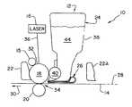
- FIG. 1is a simplified, side view of a portion of an electrophotographic imaging apparatus of the present invention
- FIG. 2is an end view of the light pipe and integral light guide of the pre-transfer erase assembly shown in FIG. 1;
- FIG. 3is a top view of the pre-transfer erase assembly shown in FIGS. 1 and 2;
- FIG. 4is a simplified, side view of a portion of another embodiment of an electrophotographic imaging apparatus of the present invention.
- FIG. 5is an end view of the light pipe and integral light guide of the pre-transfer erase assembly shown in FIG. 4;
- FIG. 6is an end view of another embodiment of a monolithic light pipe and light guide of the present invention.
- FIG. 7is a simplified, side view of yet another embodiment of an electrophotographic imaging apparatus of the present invention.
- FIG. 8is a top view of the light guide shown in FIG. 7 .
- EP image forming apparatus 10is in the form of a multi-color image forming apparatus with a plurality of imaging stations 12 .
- Each imaging station 12is associated with a respective color toner which is applied to image substrate 14 .
- Each imaging station 12generally includes a laser 16 , PC drum 18 , transfer roll 20 , cleaner 22 , toner cartridge assembly 24 , and pre-transfer erase assembly 26 .
- Each imaging station 12is sequentially arranged along a substrate path 28 aligned generally coincident with image substrate 14 moving in advance direction 30 .
- a single imaging station 12is shown in FIG. 1 with respect to a cleaner 22 A of an adjacent imaging station (only partially illustrated) located upstream therefrom, with respect to advance direction 30 .
- Laser 16scans a laser beam 36 in a scan direction (perpendicular to the drawing of FIG. 1) across PC drum 18 at selected locations within a scan line.
- Laser 16may be configured in a conventional manner, such as with a laser source, rotating polygonal mirror, fold mirrors, lenses, etc. For ease of illustration and description, laser 16 is shown schematically in FIG. 1 .
- PC drum 18also may be of known construction, and includes a PC outer surface 32 on which a latent image is formed.
- Transfer roll 20is positioned adjacent to PC drum 18 and defines a nip there between.
- Image substrate 14travels within substrate path 28 through transfer nip 34 .
- Cleaner 22is used to remove toner particles from outer surface 32 of PC drum 18 and thereby clean PC drum 18 prior to charging by charge roll 15 and exposure from a scanned laser beam 36 generated by laser 16 .
- Toner cartridge assembly 24includes a housing 38 and developer roll 40 . Toner 44 of a predetermined color is carried within housing 38 and is applied to PC drum 18 at selected locations in known manner.
- Image substrate 14receives an image corresponding to the latent image formed on PC drum 18 that is rendered visible by color toner at developer roll 40 .
- Image substrate 14may be in the form of a print medium transported upon an associated transport belt or an ITM such as an intermediate transfer belt.
- image substrate 14is assumed to be an intermediate transfer belt which carries the developed image to a nip located downstream for transfer to a print medium.
- Each imaging station 12applies a different color toner carried within a corresponding toner cartridge assembly 24 to intermediate transfer belt 14 in a sequential manner within a common image area to develop the multi-color image on intermediate transfer belt 14 .
- Pre-transfer erase assembly 26shown in more detail in FIGS. 2 and 3, includes a light pipe 46 , light guide 48 and one or more source lights 50 .
- Pre-transfer erase assembly 26in the embodiment shown, is carried by frame 52 of EP image forming apparatus 10 as shown in FIG. 3 .
- pre-transfer erase assembly 26may also optionally be carried by an associated toner cartridge assembly 24 .
- Light pipe 46is formed as a hollow pipe having an inner surface 54 and outer surface 56 .
- Light pipe 46 as well as light guide 48are each formed from a clear, translucent or opaque plastic which allows light within light pipe 46 to pass there through. Outer surface 56 is roughened or textured to scatter light within light pipe 46 .
- a reflective coating 58is applied to roughened outer surface 56 to reflect and scatter light within light pipe 46 .
- reflective coating 58is in the form of reflective paint; however, reflective coating 58 may be of any suitable reflecting material, such as vacuum deposited metal, sputtered metal, plated metal, etc.
- Light guide 48is attached to and extends from light pipe 46 .
- light guide 48is monolithically formed with light pipe 46 , and includes a slot-shaped light-emitting outlet opening 60 from which light exits.
- Outlet opening 60is positioned at a predetermined distance away from outer surface 32 of PC drum 18 .
- Outlet opening 60may be configured to transmit light against PC drum 18 in a direction generally parallel to advance direction 30 , as illustrated in FIGS. 1 and 2.
- outlet opening 60may be configured to transmit light against PC drum 18 at a different predetermined angle relative to substrate path 28 and advance direction 30 .
- outlet opening 60may be tapered, angled and/or curved to transmit light against PC drum 18 at a predetermined angle.
- light guide 48may include a lens (not shown) at outlet opening 60 to direct and/or diffuse light in a predetermined manner against PC drum 18 .
- light guide 48is substantially plate-shaped and defines a slot-shaped outlet opening 60 which communicates with the interior of light pipe 46 .
- Light guide 48includes an outer surface 62 to which a reflective coating 58 is applied, such as reflective paint, etc. as described above. Outer surface 62 may also optionally be configured with a roughened surface to reflect and diffuse light.
- light pipe 46is formed from a transparent material such as transparent plastic. If light pipe 46 is formed from a non-transparent material, the roughened surface and/or reflective coating 58 may be applied to inner surface 54 . In the embodiment shown, outer surface 56 is roughened and reflective coating 58 is applied thereover for manufacturing purposes.
- Light pipe 46may also be formed from a white, high reflectivity plastic like polystyrene loaded with 7.5-10% Ti O 2 ; thus, not requiring painting or coating.
- Lights 50are configured to provide adequate light within light pipe 46 and light guide 48 to transmit light with a predetermined energy level against PC drum 18 .
- each light 50may be configured as an LED, laser diode, incandescent lamp, etc.
- lights 50are in the form of a pair of LED's at each longitudinal end of light pipe 46 .
- a single pair of LED's 50may be placed at one end of light pipe 46 , with the opposite end being covered with a reflective material.
- a light source intensity of nominally 1000 micro-watts ( ⁇ W) at 660 nanometer (nM)generates approximately 50 ⁇ W of radiant energy at PC drum 18 corresponding to a light pipe/light guide optical efficiency of about 5%.
- ⁇ Wmicro-watts
- nMnanometer
- ⁇ J/cm 2micro-joules per centimeter squared
- one or more lights 50may be configured as a laser diode generating a light source intensity of about 5000 ⁇ W.
- a bright, incandescent lampmay also be utilized and controllably actuated, but has the disadvantage of slow turn-on and turn-off times associated therewith.
- the distance from PC drum 18 to the back of housing 38 of toner cartridge assembly 24is approximately 38 millimeters. Moreover, the distance between the bottom of housing 38 and the top of image substrate 14 is approximately 3 millimeters.
- Light guide 48is approximately 1 millimeter thick and 35 millimeters wide (parallel to image substrate 14 ). Light pipe 46 is positioned adjacent to the rear of housing 38 .
- FIGS. 4 and 5illustrate another embodiment of a pre-transfer erase assembly 70 of the present invention.
- Pre-transfer erase assembly 70also includes a light pipe 72 and a light guide 74 .
- Light guide 74is attached to and extends from light pipe 72 .
- Light pipe 72is formed as a hollow pipe from a transparent plastic.
- Light pipe 72includes a roughened outer surface 76 and reflective coating 78 , similar to outer surface 56 and reflective coating 58 shown in FIG. 2 .
- Light guide 74is constructed as a solid piece which is attached to light pipe 72 .
- light guide 74is formed from a transparent plastic having a fluorescent dye therein.
- a fluorescent dyefor example, Albis Deep Red #1263 R LISA plastic (acrylic or polycarbonate) has been found to work satisfactorily.
- the fluorescent dye within the plasticis selected to absorb light at the wave length of the light source and emit light in the range of spectral sensitivity of PC drum 18 .
- light guide 74is formed from a plastic which absorbs light at a wavelength of between 370 to 550 nM and emits light at approximately 650 nM.
- Light guide 74includes a light emitting outlet 80 having a predetermined convex shape (i.e., a lens) to direct light against PC drum 18 with a predetermined pattern.
- Light guide 74has an outer surface 82 to which reflective coating 78 is applied. Reflective coating 78 on outer surface 82 eliminates loss of light associated with (e.g., toner) contamination of outer surface 82 .
- one or more lights 50are positioned to emit light into light pipe 72 , similar to lights 50 shown in FIG. 3 .
- one or more yellow or green LED'sare positioned at one or both ends of light pipe 72 to obtain a desired illumination intensity at PC drum 18 for effecting pre-transfer erase of PC drum 18 .
- FIG. 6illustrates another embodiment of a pre-transfer erase assembly 90 of the present invention.
- Pre-transfer erase assembly 90includes a light pipe 92 and a light guide 94 which are formed together as a solid, monolithic body.
- Light pipe 92includes a roughened outer surface 96 and light guide 94 includes an outer surface 98 , each of which are coated by a reflective coating 100 .
- each of light pipe 92 and light guide 94are formed from Albis Deep Red #1263 R LISA transparent plastic (acrylic or polycarbonate) with a fluorescent dye therein.
- One or more lights 50preferably in the form of yellow or green LED's, with a suitable illumination intensity are placed at one or both ends of light pipe 92 for illumination of PC drum 18 .
- Pre-transfer erase assembly 110may be advantageously utilized where space requirements limit the use of a light pipe at the rear of housing 38 of toner cartridge assembly 24 .
- Pre-transfer erase assembly 110is constructed from a plastic having a fluorescent dye therein, such as the Albis Deep Red #1263 R LISA plastic described above with reference to the embodiment shown in FIGS. 4-6.
- Pre-transfer erase assembly 110basically consists of a light guide 112 without an attached light pipe.
- Light guide 112may include a roughened outer surface, and optionally may also include a reflective coating thereon.
- Light guide 112includes an outlet in the form of a light scattering surface 114 opposite the emitting surface which is configured to produce relatively uniform illumination at PC drum 18 .
- light scattering surface 114has a serrated edge as shown.
- One or more lights 50are positioned at one or both ends of light guide 112 to achieve a desired illumination intensity at PC drum 18 .
- four lights 50 in the form of yellow or green LED'swhich emit light at a wavelength of between 370 to 550 nM are utilized.
- the fluorescent dye within light guide 112emits light in the range of the spectral sensitivity of PC drum 18 (e.g., at a wavelength of approximately 650 nM).
Landscapes
- Physics & Mathematics (AREA)
- General Physics & Mathematics (AREA)
- Electrostatic Charge, Transfer And Separation In Electrography (AREA)
Abstract
Description
Claims (26)
Priority Applications (1)
| Application Number | Priority Date | Filing Date | Title |
|---|---|---|---|
| US09/594,871US6356726B1 (en) | 2000-06-15 | 2000-06-15 | Electrophotographic printer with compact pre-transfer erase assembly |
Applications Claiming Priority (1)
| Application Number | Priority Date | Filing Date | Title |
|---|---|---|---|
| US09/594,871US6356726B1 (en) | 2000-06-15 | 2000-06-15 | Electrophotographic printer with compact pre-transfer erase assembly |
Publications (1)
| Publication Number | Publication Date |
|---|---|
| US6356726B1true US6356726B1 (en) | 2002-03-12 |
Family
ID=24380761
Family Applications (1)
| Application Number | Title | Priority Date | Filing Date |
|---|---|---|---|
| US09/594,871Expired - LifetimeUS6356726B1 (en) | 2000-06-15 | 2000-06-15 | Electrophotographic printer with compact pre-transfer erase assembly |
Country Status (1)
| Country | Link |
|---|---|
| US (1) | US6356726B1 (en) |
Cited By (8)
| Publication number | Priority date | Publication date | Assignee | Title |
|---|---|---|---|---|
| US20030202820A1 (en)* | 2002-04-24 | 2003-10-30 | Samsung Electronics Co., Ltd. | Image forming apparatus |
| US20040005170A1 (en)* | 2002-07-02 | 2004-01-08 | Samsung Electronics Co., Ltd. | Image forming device |
| US20050002691A1 (en)* | 2003-07-04 | 2005-01-06 | Jung Woo-Chul | Electrophotographic printer |
| US20050025520A1 (en)* | 2003-06-24 | 2005-02-03 | Eisaku Murakami | Image forming apparatus and process cartridge |
| US20080159783A1 (en)* | 2007-01-03 | 2008-07-03 | Samsung Electronics Co., Ltd. | Developing unit and image forming apparatus having the same |
| JP2013113901A (en)* | 2011-11-25 | 2013-06-10 | Kyocera Document Solutions Inc | Image forming apparatus |
| JP2016126068A (en)* | 2014-12-26 | 2016-07-11 | 京セラドキュメントソリューションズ株式会社 | Image forming apparatus, and light guide member |
| US20190094723A1 (en)* | 2017-09-27 | 2019-03-28 | Konica Minolta, Inc. | Image forming method and image forming device |
Citations (18)
| Publication number | Priority date | Publication date | Assignee | Title |
|---|---|---|---|---|
| US4025180A (en)* | 1973-10-30 | 1977-05-24 | Minolta Camera Kabushiki Kaisha | Transfer type electrophotographic copying apparatus |
| US4077711A (en) | 1974-05-28 | 1978-03-07 | Ricoh Company, Ltd. | Electrophotographic copying apparatus of wet developing type |
| US4342511A (en) | 1980-08-20 | 1982-08-03 | International Business Machines Corporation | Illumination system having an efficient light guide |
| US4779166A (en)* | 1986-12-19 | 1988-10-18 | Fujitsu Limited | Illuminating apparatus |
| US4843427A (en) | 1987-01-05 | 1989-06-27 | Sharp Kabushiki Kaisha | Selective charge removal system for copier |
| US5214536A (en) | 1991-03-11 | 1993-05-25 | International Business Machines Corporation | Illumination device for a document line scanner |
| US5255171A (en)* | 1991-11-27 | 1993-10-19 | Clark L Douglas | Colored light source providing intensification of initial source illumination |
| US5506662A (en) | 1993-07-19 | 1996-04-09 | Kabushiki Kaisha Toshiba | Image forming apparatus including an image bearing member and an erasing device for erasing a portion of an image from the image bearing member |
| US5559580A (en) | 1994-06-08 | 1996-09-24 | Minolta Co., Ltd. | Image forming apparatus having a bipolar photosensitive member |
| US5575549A (en) | 1994-08-12 | 1996-11-19 | Enplas Corporation | Surface light source device |
| US5604571A (en) | 1995-01-26 | 1997-02-18 | Hamamatsu Photonics K.K. | Image- forming apparatus having imaging x-ray generation means |
| US5664862A (en) | 1994-11-29 | 1997-09-09 | Precision Lamp, Inc. | Edge light for panel display |
| US5709447A (en) | 1994-11-30 | 1998-01-20 | Sharp Kabushiki Kaisha | Lighting device |
| US5808650A (en) | 1995-08-02 | 1998-09-15 | Sanyo Electric Co., Ltd. | Image forming apparatus with light emitting element head |
| US5810463A (en) | 1994-11-28 | 1998-09-22 | Nikon Corporation | Illumination device |
| US5835814A (en) | 1996-01-26 | 1998-11-10 | Rohm Co. Ltd. | Electrophotographic method and apparatus for forming color images, and exposure unit therefor |
| US5966560A (en)* | 1995-08-29 | 1999-10-12 | Minolta Co., Ltd. | Image forming apparatus with enhanced pretransfer erasing |
| US6026269A (en)* | 1997-07-11 | 2000-02-15 | Canon Kabushiki Kaisha | Image forming apparatus with varying conveying speed |
- 2000
- 2000-06-15USUS09/594,871patent/US6356726B1/ennot_activeExpired - Lifetime
Patent Citations (18)
| Publication number | Priority date | Publication date | Assignee | Title |
|---|---|---|---|---|
| US4025180A (en)* | 1973-10-30 | 1977-05-24 | Minolta Camera Kabushiki Kaisha | Transfer type electrophotographic copying apparatus |
| US4077711A (en) | 1974-05-28 | 1978-03-07 | Ricoh Company, Ltd. | Electrophotographic copying apparatus of wet developing type |
| US4342511A (en) | 1980-08-20 | 1982-08-03 | International Business Machines Corporation | Illumination system having an efficient light guide |
| US4779166A (en)* | 1986-12-19 | 1988-10-18 | Fujitsu Limited | Illuminating apparatus |
| US4843427A (en) | 1987-01-05 | 1989-06-27 | Sharp Kabushiki Kaisha | Selective charge removal system for copier |
| US5214536A (en) | 1991-03-11 | 1993-05-25 | International Business Machines Corporation | Illumination device for a document line scanner |
| US5255171A (en)* | 1991-11-27 | 1993-10-19 | Clark L Douglas | Colored light source providing intensification of initial source illumination |
| US5506662A (en) | 1993-07-19 | 1996-04-09 | Kabushiki Kaisha Toshiba | Image forming apparatus including an image bearing member and an erasing device for erasing a portion of an image from the image bearing member |
| US5559580A (en) | 1994-06-08 | 1996-09-24 | Minolta Co., Ltd. | Image forming apparatus having a bipolar photosensitive member |
| US5575549A (en) | 1994-08-12 | 1996-11-19 | Enplas Corporation | Surface light source device |
| US5810463A (en) | 1994-11-28 | 1998-09-22 | Nikon Corporation | Illumination device |
| US5664862A (en) | 1994-11-29 | 1997-09-09 | Precision Lamp, Inc. | Edge light for panel display |
| US5709447A (en) | 1994-11-30 | 1998-01-20 | Sharp Kabushiki Kaisha | Lighting device |
| US5604571A (en) | 1995-01-26 | 1997-02-18 | Hamamatsu Photonics K.K. | Image- forming apparatus having imaging x-ray generation means |
| US5808650A (en) | 1995-08-02 | 1998-09-15 | Sanyo Electric Co., Ltd. | Image forming apparatus with light emitting element head |
| US5966560A (en)* | 1995-08-29 | 1999-10-12 | Minolta Co., Ltd. | Image forming apparatus with enhanced pretransfer erasing |
| US5835814A (en) | 1996-01-26 | 1998-11-10 | Rohm Co. Ltd. | Electrophotographic method and apparatus for forming color images, and exposure unit therefor |
| US6026269A (en)* | 1997-07-11 | 2000-02-15 | Canon Kabushiki Kaisha | Image forming apparatus with varying conveying speed |
Cited By (16)
| Publication number | Priority date | Publication date | Assignee | Title |
|---|---|---|---|---|
| US20030202820A1 (en)* | 2002-04-24 | 2003-10-30 | Samsung Electronics Co., Ltd. | Image forming apparatus |
| US7027757B2 (en)* | 2002-04-24 | 2006-04-11 | Samsung Electronics Co., Ltd. | Image forming apparatus including a subsidiary transfer part having a fiber optic guide |
| US20040005170A1 (en)* | 2002-07-02 | 2004-01-08 | Samsung Electronics Co., Ltd. | Image forming device |
| US7319835B2 (en)* | 2002-07-02 | 2008-01-15 | Samsung Electronics Co., Ltd. | Image forming device having first and second light providing units |
| US20050025520A1 (en)* | 2003-06-24 | 2005-02-03 | Eisaku Murakami | Image forming apparatus and process cartridge |
| US7400844B2 (en)* | 2003-06-24 | 2008-07-15 | Ricoh Company Limited | Image forming apparatus and process cartridge with a cleaner for removing toner from an image bearing member |
| US20050002691A1 (en)* | 2003-07-04 | 2005-01-06 | Jung Woo-Chul | Electrophotographic printer |
| US7082281B2 (en)* | 2003-07-04 | 2006-07-25 | Samsung Electronics Co., Ltd. | Electrophotographic printer having movable pre-transfer erasing unit |
| EP1942384A1 (en)* | 2007-01-03 | 2008-07-09 | Samsung Electronics Co., Ltd. | Developing unit and image forming apparatus having the same |
| US20080159783A1 (en)* | 2007-01-03 | 2008-07-03 | Samsung Electronics Co., Ltd. | Developing unit and image forming apparatus having the same |
| US7894749B2 (en) | 2007-01-03 | 2011-02-22 | Samsung Electronics Co., Ltd. | Image forming apparatus capable of resetting and decreasing a surface potential of a photosensitive member |
| JP2013113901A (en)* | 2011-11-25 | 2013-06-10 | Kyocera Document Solutions Inc | Image forming apparatus |
| JP2016126068A (en)* | 2014-12-26 | 2016-07-11 | 京セラドキュメントソリューションズ株式会社 | Image forming apparatus, and light guide member |
| US20190094723A1 (en)* | 2017-09-27 | 2019-03-28 | Konica Minolta, Inc. | Image forming method and image forming device |
| JP2019061061A (en)* | 2017-09-27 | 2019-04-18 | コニカミノルタ株式会社 | Image forming method and image forming apparatus |
| US10627730B2 (en)* | 2017-09-27 | 2020-04-21 | Konica Minolta, Inc. | Image forming method and image forming device |
Similar Documents
| Publication | Publication Date | Title |
|---|---|---|
| EP1511289B1 (en) | Lighting device, image reading apparatus , and image forming apparatus | |
| US5526190A (en) | Optical element and device for providing uniform irradiance of a surface | |
| KR100472468B1 (en) | Optical guide and image forming apparatus employing it | |
| US8417153B2 (en) | Light guide and charge eliminating unit, image forming apparatus and image reading apparatus having the same | |
| US8285186B2 (en) | Laser fixing device and image forming apparatus | |
| US8406669B2 (en) | Fixing device, fixing method, and image forming apparatus for fixing a toner image using a first laser unit and a second laser unit | |
| KR20020050711A (en) | Image forming apparatus and process cartridge detachably attachable to the same | |
| GB2300729A (en) | Toner density sensor for image forming apparatus | |
| US6356726B1 (en) | Electrophotographic printer with compact pre-transfer erase assembly | |
| US10401770B2 (en) | Discriminating device and image forming apparatus | |
| JP2011227425A (en) | Static eliminator | |
| DE19958924B4 (en) | A developing apparatus and image forming apparatus using the developing apparatus and methods for determining a toner end condition | |
| JP3993190B2 (en) | Photostatic device and image forming apparatus having the same | |
| US7619787B2 (en) | Method and apparatus for illuminating a document | |
| CN102621866A (en) | Light irradiation element, image forming structure, and image forming apparatus | |
| US5552863A (en) | Xerographic printer wherein exposure and development are performed on opposite sides of the photoreceptor | |
| EP0373868A3 (en) | Electrophotographic method | |
| US5756151A (en) | Paper for forming images and image forming process | |
| US6052135A (en) | Combination erase bar and belt position detector system for use with an electrophotographic imaging system | |
| US6324373B1 (en) | Pre-transfer system in an image forming apparatus | |
| US7805094B2 (en) | Image forming apparatus and charge removing device thereof | |
| CN101527769A (en) | Illumination unit, image read apparatus and image forming apparatus | |
| JP2008032996A (en) | Document illumination device, image reading device, color document reading device, and image forming device | |
| US5289235A (en) | Image producing apparatus | |
| KR100261086B1 (en) | An apparatus for forming image |
Legal Events
| Date | Code | Title | Description |
|---|---|---|---|
| AS | Assignment | Owner name:LEXMARK INTERNATIONAL, INC., KENTUCKY Free format text:ASSIGNMENT OF ASSIGNORS INTEREST;ASSIGNORS:CAMPBELL, ALAN STIRLING;DENTON, GARY ALLEN;REAM, GREGORY LAWRENCE;REEL/FRAME:010914/0783 Effective date:20000615 | |
| STCF | Information on status: patent grant | Free format text:PATENTED CASE | |
| FEPP | Fee payment procedure | Free format text:PAYOR NUMBER ASSIGNED (ORIGINAL EVENT CODE: ASPN); ENTITY STATUS OF PATENT OWNER: LARGE ENTITY | |
| FPAY | Fee payment | Year of fee payment:4 | |
| FPAY | Fee payment | Year of fee payment:8 | |
| FPAY | Fee payment | Year of fee payment:12 | |
| AS | Assignment | Owner name:CHINA CITIC BANK CORPORATION LIMITED, GUANGZHOU BR Free format text:PATENT SECURITY AGREEMENT;ASSIGNOR:LEXMARK INTERNATIONAL, INC.;REEL/FRAME:046989/0396 Effective date:20180402 | |
| AS | Assignment | Owner name:CHINA CITIC BANK CORPORATION LIMITED, GUANGZHOU BR Free format text:CORRECTIVE ASSIGNMENT TO CORRECT THE INCORRECT U.S. PATENT NUMBER PREVIOUSLY RECORDED AT REEL: 046989 FRAME: 0396. ASSIGNOR(S) HEREBY CONFIRMS THE PATENT SECURITY AGREEMENT;ASSIGNOR:LEXMARK INTERNATIONAL, INC.;REEL/FRAME:047760/0795 Effective date:20180402 | |
| AS | Assignment | Owner name:LEXMARK INTERNATIONAL, INC., KENTUCKY Free format text:RELEASE BY SECURED PARTY;ASSIGNOR:CHINA CITIC BANK CORPORATION LIMITED, GUANGZHOU BRANCH, AS COLLATERAL AGENT;REEL/FRAME:066345/0026 Effective date:20220713 |