US6356622B1 - System and apparatus for enhancing a network link - Google Patents
System and apparatus for enhancing a network linkDownload PDFInfo
- Publication number
- US6356622B1 US6356622B1US09/389,333US38933399AUS6356622B1US 6356622 B1US6356622 B1US 6356622B1US 38933399 AUS38933399 AUS 38933399AUS 6356622 B1US6356622 B1US 6356622B1
- Authority
- US
- United States
- Prior art keywords
- calling party
- link
- backup
- connection
- network
- Prior art date
- Legal status (The legal status is an assumption and is not a legal conclusion. Google has not performed a legal analysis and makes no representation as to the accuracy of the status listed.)
- Expired - Lifetime
Links
- 230000002708enhancing effectEffects0.000titledescription4
- 238000004891communicationMethods0.000claimsabstractdescription18
- 238000000034methodMethods0.000claimsdescription24
- 238000012913prioritisationMethods0.000abstractdescription9
- 238000001514detection methodMethods0.000description12
- 238000010586diagramMethods0.000description5
- 230000005055memory storageEffects0.000description4
- 238000012986modificationMethods0.000description4
- 230000004048modificationEffects0.000description4
- 230000005540biological transmissionEffects0.000description3
- 230000007246mechanismEffects0.000description3
- 238000010200validation analysisMethods0.000description3
- 230000001010compromised effectEffects0.000description2
- 238000012423maintenanceMethods0.000description2
- 239000008186active pharmaceutical agentSubstances0.000description1
- 230000001413cellular effectEffects0.000description1
- 238000011156evaluationMethods0.000description1
- 239000000284extractSubstances0.000description1
- 230000000977initiatory effectEffects0.000description1
- 238000007726management methodMethods0.000description1
- 230000035755proliferationEffects0.000description1
- 230000001737promoting effectEffects0.000description1
- 238000012360testing methodMethods0.000description1
Images


Classifications
- H—ELECTRICITY
- H04—ELECTRIC COMMUNICATION TECHNIQUE
- H04M—TELEPHONIC COMMUNICATION
- H04M3/00—Automatic or semi-automatic exchanges
- H04M3/08—Indicating faults in circuits or apparatus
- H04M3/12—Marking faulty circuits "busy"; Enabling equipment to disengage itself from faulty circuits ; Using redundant circuits; Response of a circuit, apparatus or system to an error
- H—ELECTRICITY
- H04—ELECTRIC COMMUNICATION TECHNIQUE
- H04M—TELEPHONIC COMMUNICATION
- H04M3/00—Automatic or semi-automatic exchanges
- H04M3/42—Systems providing special services or facilities to subscribers
- H04M3/42195—Arrangements for calling back a calling subscriber
- H—ELECTRICITY
- H04—ELECTRIC COMMUNICATION TECHNIQUE
- H04M—TELEPHONIC COMMUNICATION
- H04M2242/00—Special services or facilities
- H04M2242/06—Lines and connections with preferential service
- H—ELECTRICITY
- H04—ELECTRIC COMMUNICATION TECHNIQUE
- H04M—TELEPHONIC COMMUNICATION
- H04M3/00—Automatic or semi-automatic exchanges
- H04M3/42—Systems providing special services or facilities to subscribers
- H04M3/42025—Calling or Called party identification service
- H04M3/42034—Calling party identification service
- H04M3/42042—Notifying the called party of information on the calling party
- H—ELECTRICITY
- H04—ELECTRIC COMMUNICATION TECHNIQUE
- H04M—TELEPHONIC COMMUNICATION
- H04M3/00—Automatic or semi-automatic exchanges
- H04M3/42—Systems providing special services or facilities to subscribers
- H04M3/42025—Calling or Called party identification service
- H04M3/42034—Calling party identification service
- H04M3/42059—Making use of the calling party identifier
Definitions
- the present inventiongenerally relates to telecommunication networks, and more particularly to a system and method for providing a robust network having enhanced security and integrity.
- high capacity usersdefine the endpoints of a telecommunications network.
- Service providerslocal area networks (LANs), and private branch exchanges (PBXs), are all examples of such high capacity users.
- LANslocal area networks
- PBXsprivate branch exchanges
- the incoming/outgoing network link connected to such high capacity usersincludes a high capacity trunk line, such as a T1, T3, E3, OC3, DS, or DSL line, which may interconnect with various other users, through, for example, a point-to-point connection or a frame relay network.
- T1, T3, E3, OC3, DS, or DSL linewhich may interconnect with various other users, through, for example, a point-to-point connection or a frame relay network.
- T1, T3, E3, OC3, DSor DSL line
- the endpointdetects a fault or breakage in any channel(s) of the T1 line
- present systemsoperate to reroute the entirety of the data traffic across that T1 line through another port, whether that be a secondary T1 line or an alternative backup link.
- fractional or partial line faultsare often encountered, making such a global rerouting of data wasteful and unnecessary.
- data transmitted across a frame relay networke.g., packet-switched data
- packet-switched dataoften suffers only a partial fault, or a network breakage at some intermediate point across which only a portion of the data to the ultimate endpoint traverses.
- the present inventionis generally directed to an apparatus for establishing a backup communications link for rerouting data in a telecommunications network.
- the apparatusestablishes a primary network link between a calling party and a called party, and examines connection setup information at the called party location to identify the calling party. Thereafter, the apparatus stores identification information related to the calling party. Upon identification of a fault condition in the network link between the calling party and the called party, the apparatus retrieves the stored identification information of the calling party from the called party and uses the retrieved identification information to establish a backup network link. Alternatively, the apparatus can use the identification information of the calling party to identify a backup link path different from the original link path.
- the primary network linkmay be a T1 link, an ISDN link, or a POTS link.
- the linkmay be a point-to-point link, a permanent virtual circuit, a packet-switched frame relay circuit, or other similar network link.
- the apparatusutilizes a lookup table or other database to store party profile information, which may include security information or priority data. Identification information related to the calling party is used to access/index such a table or database.
- the apparatusestablishes a secured data link between a calling party and a called party.
- the apparatusreceives a network access request from a remote user, obtains the calling party identification information, and uses the calling party identification information to access a lookup table.
- the apparatusdetermines whether a profile exists in the lookup table that corresponds to the calling party. If so, the apparatus further confirms from information provided in the lookup table, whether that user is entitled to access the system. If so, the apparatus directs the system to establish the connection with the remote user.
- the systemmay provide an added level of security by requiring the remote user to enter a password, as well.
- this aspect of the inventionreceives a signal from a calling party requesting a network link, and examines link setup information within the received signal for the called party to identify the calling party.
- the apparatusaccesses a memory storage area using the identification information associated with the calling party to retrieve information related to the calling party, and evaluates security data within the retrieved information. If the security data permits the establishment of a connection, then the apparatus directs the system to establish a network link with the calling party.
- the apparatusprovides for prioritizing the establishment and maintenance of network links.
- the apparatusestablishes a first network link with a first calling party and receiving a signal from a second calling party that is requesting the establishment of a second network link.
- the apparatusexamines the link setup information for the calling party to identify the second calling party.
- the apparatusaccesses a memory storage area using the identification information related to the second calling party for use in evaluating user priority, and allocates resources in accordance with the evaluated information.
- the apparatusallocates resources by assessing the priority of the calling party with respect to user(s) utilizing established network connections. More specifically, the apparatus may terminate the first network connection if the second calling party has a higher priority and system resources are unable to support the maintenance of both network links simultaneously.
- the apparatuscontrollably establishes a network connection with remote equipment associated with a calling party.
- the apparatusincludes receiving means for receiving a signal from a calling party seeking the establishment of a network link, and examining means for examining connection setup information included in the received signal, the network setup information including the caller identification information, the Internet protocol (IP) address, or data-link connection identifiers (DLCIs) associated with the calling party.
- IPInternet protocol
- DLCIsdata-link connection identifiers
- FIG. 1is a top-level system diagram illustrating a telecommunications network link backup feature of the present invention
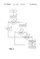
- FIG. 2is a software flowchart illustrating steps in an embodiment implementing the telecommunications network link backup aspect of the present invention
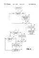
- FIG. 3is a software flowchart illustrating steps in an embodiment implementing the prioritization aspect of the present invention
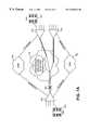
- FIG. 4is a software flowchart illustrating steps in an embodiment implementing the enhanced security aspect of the present invention
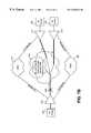
- FIG. 5is a top-level software flowchart illustrating steps of an embodiment implementing the combined functionality of the various aspects of the present invention
- FIGS. 6A and 6Bare timing diagrams illustrating the allocation and deallocation of network connection originating and network connection called peers;
- FIGS. 7A-7Ddepict various embodiments and operating environments illustrating the concepts and teachings of the present invention.
- FIG. 8depicts a top-level view of the apparatus illustrating the functionality of the various aspects of the invention, specifically, link setup examination and control, network resource management, fault detection, priority detection and control, and security detection and control.
- FIG. 1depicts a top-level system diagram, illustrating a telecommunications network connection backup feature for the present invention. More specifically, FIG. 1 generally illustrates a network system, designated by reference numeral 10 , which connects a first or calling endpoint 12 and a second or called endpoint 14 , in communication across a network 16 .
- the network 16could be a POTS network, an ISDN network, a frame relay network, or virtually any other network.
- the link 18 connecting the endpoint 14 to the network 16may, for example, be a T1 trunk, which is capable of handling high capacity data throughput.
- each endpoint 12 and 14includes a primary interface 20 and a secondary interface 22 .
- the primary interfaceis configured to interface with the primary network link 18
- the secondary interface 22is designed to interface with a backup line, as will be described in more detail below.
- the primary interface 20 and secondary interface 22need not necessarily be separate and distinct modules, but are depicted that way for purposes of illustration.
- the primary network link 18 and any secondary network link established by the systemcould be maintained via a radio frequency carrier.
- the endpoint 14may be a node in, for example, a corporate environment. In this regard, it may communicate with a network 24 and/or a private branch exchange (PBX) 26 .
- PBXprivate branch exchange
- the system 10provides a means for establishing a backup link between endpoints 12 and 14 in the event that a fault (either total or partial) occurs in the network link between endpoints 12 and 14 .
- link 18is a high capacity line, such as a T3 trunk.
- the backup linkcould, likewise, be provided over a T1 trunk, or alternatively over a slower speed line such as an ISDN-BRI 28 or a POTS 30 .
- the called endpoint 14is able to identify the calling endpoint, in order to establish a backup network link. As will be described below, this is accomplished by utilizing the user identification information transmitted to the called endpoint 14 .
- the endpoint 14may detect this fault, and upon fault detection initiate its fault handling or network connection backup routine.
- the endpoint 14utilizes the network connection user identification information that was transmitted to it upon establishment of the connection with network connection requested party 12 .
- this network connection user identification informationcould be in the form of what is currently known as call waiting/caller identification.
- This user informationis inserted by the first central office (i.e., the central office adjacent endpoint 12 ) in the link between endpoint 12 and endpoint 14 .
- the endpoint 14may utilize this network connection user identification information to access, for example, a lookup table or database where it may retrieve pre-stored information about the user at endpoint 12 .
- a lookup table or databasewhere it may retrieve pre-stored information about the user at endpoint 12 .
- some prior knowledge(which is stored in the lookup table or database) is known about the user at endpoint 12 .
- the entities at endpoints 12 and 14could be corporate affiliates that communicate regularly across network 16 .
- corporate employees that are attached to network 25 at endpoint 12may communicate with corporate employees that are attached to network 24 at endpoint 14 .
- network 16is a frame relay network and the network connection backup instituted by endpoint 14 is to take place across the same frame relay network, then it may be necessary for endpoint 14 to re-map DLCIs, which identify all multiple logical connections to be multiplexed over the same channel. That is, in a frame relay environment, the network connection user identification information may be mapped via the lookup table to a preferred set of DLCIs which, in the event of a fault, may be re-mapped.
- the network connection user identification informationmay be mapped to logical IP addresses, in the event that endpoint 14 is a router.
- the essence, of this aspect of the inventionis the use of the network connection user identification information to define (by way of a database or lookup table) a backup or alternative dial up connection.
- network user identification informationis utilized for purposes of enhancing system security.
- prior art systemsare known for implementing password protection in order to employ some means of system security.
- a network user requesting access to an endpoint 14may be required to input a password in order to access the system.
- anyone that may learn this passwordcould gain unauthorized access to the system.
- This type of password protectionbecomes increasingly suspect in multi-point, interconnecting networks 16 , where password information transmitted across the network becomes increasingly susceptible to unauthorized detection. Therefore, as an added means of protection, a system constructed in accordance with one aspect of the present invention may employ network connection user identification information as a sole or secondary means of security.
- a given endpoint 14would be preconfigured to accept network connection requests only from certain predefined users, and more specifically, from predefined endpoints for backup purposes. Since caller identification information is inserted at a local exchange, rather than at a user endpoint itself, this mechanism for security is less susceptible to deceit or failure. Of course, as an added means of protection, a system endpoint could require not only that a network connection request be placed from particular user locations, but also that the calling party enter an appropriate password, as a secondary level of security and protection.
- Another aspect of the present inventionrelates to the use of network user identification information in connection with prioritization. While the varying needs and circumstances that give rise to the need for being able to prioritize network connection requests are too numerous to mention, suffice it to say that it is often desirable for an endpoint to be able to prioritize incoming network connection requests. This is particularly true when there is a limited bandwidth for transmission across the primary channel of communication. For example, consider a small business that does not have the resources and needs to justify expenditures for a high volume T1 line. Instead, it may purchase an ISDN line, or even more economically, one or two POTS lines.
- This companymay deem network connection requests received from a particular location to be of utmost importance, for whatever reason, and therefore want the ability to, if necessary, terminate an existing network connection in order to accept an incoming network connection request from that predetermined or pre-identified location.
- the incoming channelhas sufficient bandwidth to accept an incoming network connection request without terminating any existing network connection requests, then it may be desirable to do so. For this reason, this aspect of the present invention has increased utility in limited bandwidth situations.
- an endpointmay have a predetermined or predefined list of network user access locations, each of which receive independent priority.
- a first network connection usermay have priority over a second network connection user, which may have priority over a third network connection user, and so on.
- this systemupon receipt of an incoming network connection request, this system will determine, based upon a list of predefined priority, whether to terminate an existing network connection, and if so, which one.
- a feature known as call waiting/caller identificationis presently known in connection with POTS transmissions. This feature may be utilized by the present invention (assuming the link 18 is a POTS link or backup link) to identify the incoming network connection user and determine whether to establish a network connection, at the expense of an existing network connection.
- FIG. 2shows a software flowchart illustrating this aspect.
- the systemstrips from the call request, the caller identification information and utilizes that information to establish the call (step 42 ).
- the caller identification informationmay be used for purposes of security and/or prioritization, as will be discussed in more detail below. Assuming these threshold inquiries are met, then the system connects the call in step 44 . The call then proceeds, in a manner that is well known.
- step 46the system will disconnect (step 46 ) and wait to receive the next incoming call request. If, however, during the duration of the call, a fault is detected (step 48 ) then the system will access the internal database or lookup table, based upon the caller identification information, to receive information that defines a backup link (step 50 ). This information will vary depending upon the medium or network across which the backup link is to be made. For example, if routers define the endpoints, then the backup information will include an IP address. Alternatively, if the backup is established across a frame relay network, then DLCIs will define the backup link. Once the system retrieves this information, then at step 52 it establishes a backup connection and exchanges whatever information necessary and appropriate with the original calling party to reroute only the relevant data over the backup network link.
- FIG. 3a flowchart is provided that depicts the top-level operation of the prioritization aspect of the present invention.
- the systemvalidates the call by way of identifying the caller (at step 60 ). This validation step, having been briefly described above, will be described in more detail in connection with FIG. 4 .
- the systemdetermines from an internal database or from a look up table (at step 62 ) whether it has a prioritization profile for this particular caller. If not, it rejects the incoming call (step 64 ).
- the system of a preferred embodimentmay first check to see whether the incoming line/link has sufficient bandwidth to support the incoming network connection request. If so, it may accept the call after the step 60 validation. Of course, in such an embodiment any such accepted callers that do not have a profile are the first to be terminated once the bandwidth on the incoming link is exhausted.
- the systemretrieves a profile for that call (step 66 ). It then checks to determine, based upon the bandwidth of the incoming link, whether a channel is available to accept the call (step 68 ). If not, this system (at step 70 ) determines whether the incoming call request has a higher priority than any of the existing network connections. If not, then the incoming call is rejected (step 64 ). If so, however, the system will disconnect or terminate the existing connection with the lowest priority (step 72 ) and establish a network connection with the incoming call (step 74 ). If the system had previously established connection with callers not having a priority profile, then those calls will be deemed as having the lowest priority, and therefore the first calls to be terminated at step 72 .
- FIG. 4a top level software flowchart illustrates the security aspect provided by the present invention, in conjunction with the caller identification information. Entry into any of the steps of this flowchart assumes that the Auto Answer feature of a modem or other communicating device is enabled. Otherwise, the system would not answer incoming calls.
- the systemUpon receiving an incoming call, the system looks to determine whether it is configured for caller identification (step 80 ). This step is provided only because caller identification is not necessarily supported in all geographic locations, by analog cellular phones, or some pay telephones. If the system is configured for caller identification, however, then the system (at step 82 ) validates the caller identification from a caller identification directory, or other internal lookup table or database. From such database, the system determines whether the caller identification of the incoming call is known and therefore valid (step 84 ). If not, the connection is dropped (step 86 ) and the system may be configured to log the entry attempt from an invalid or unregistered caller identification number (step 87 ). If, however, the caller identification is validated at step 84 , then the system auto answers the call (step 88 ).
- step 90determines whether the system is configured for password access. If so, the system proceeds to step 92 where it validates the password with a password directory or lookup table. If valid (step 93 ), then the system proceeds to block 94 where it may perform other checks and routines, such as the prioritization routine discussed in connection with FIG. 3, before establishing the connection at step 96 . If, however, step 92 determines that the entered or received password is invalid, then the system proceeds to step 86 where it drops the connection.
- step 90the system is not configured for password protection, then it proceeds to step 98 where it again checks to confirm whether the system is configured for caller identification. If not, the system may proceed to connect with the incoming call (step 96 ). Alternatively, if configured for caller identification, then the caller identification validation has already occurred at steps 82 and 84 , so that system may proceed to step 94 .
- step 100The first illustrated step is step 100 , which assumes the system is operating in a steady state fashion with one or more network connections established. As illustrated, two different events can take the system out of this state. The first is the receipt of an incoming call, and the second is the identification or detection of a transmission fault.
- the systemUpon receipt of an incoming call (step 102 ), the system obtains the caller identification information and, through its internal lookup table or database, looks to see if the caller is listed as a valid caller (step 104 ).
- the systemmay also employ password protection.
- the systemdetermines whether this caller has valid access to the system and/or checks for a received password to determine whether system access should be granted (step 106 ). If the caller and/or password is invalid, then the system (at step 108 ) rejects the call. Otherwise, if the caller is a valid network user, it proceeds to step 110 where it determines if the bandwidth on the incoming/outgoing telecommunication link will support the additional caller (e.g., whether a channel is available). If so, then the system proceeds to step 112 where it establishes a connection with the incoming call and returns to step 100 . Otherwise, the system accesses the database to determine whether the incoming call has or is assigned a higher priority than in any of the presently existing network connections (step 114 ).
- the systemmay return to step 108 and reject the incoming network connection request. If, however, the incoming call is assigned a higher priority than one or more of the existing network connections, then the system terminates the lowest priority existing network connection and proceeds to step 112 where it establishes a connection with the incoming call, where it can reroute data over the backup link, and thereafter returns to step 100 .
- the second event that leads the system to depart from step 100is the detection of a fault on an established communication link. If a fault is detected (step 120 ), then the system accesses the internal database according to the caller identification of the caller on the distant end of the communication link that is corrupt. Based upon the caller identification, the system retrieves from its database the relevant information for establishing a backup link to the caller (step 122 ). It then establishes that connection, by way of backup link, and returns to step 100 .
- FIG. 6Aillustrates the allocation/deallocation of an originate peer among a generic link, a basic rate interface (to an ISDN link) and the data backup module.
- an allocate command 202 sent from the generic link to the basic rate interfacean acknowledge or OK signal 204 is returned, then the basic rate interface transmits an originate request 206 to the data backup module which dials 208 over the link and establishes a connection 210 .
- the data backup moduleUpon receiving indication that the connection is established, the data backup module then transmits to the basic rate interface a connection made signal 212 , which basic rate interface then transmits an invoke callback message 214 to the generic link and indicates that an ISDN connection has been made.
- the generic linkUpon deallocation, the generic link transmits to the basic rate interface a deallocate signal 216 , which is acknowledged 218 .
- the basic rate interfacethen transmits a terminate signal 220 to the data backup module, which then transmits a disconnect signal 222 to disconnect the established link.
- the generic linkmay again transmit an allocate signal 226 to the basic rate interface, which is acknowledged 228 as before.
- the basic rate interfacecan transmit an originate signal 230 to the data backup module, which, as described before, dials 232 to establish a connection over an ISDN line, for example. If, however, this dial backup fails 234 , the data backup module may wait a predetermined period of time and then attempt to redial 236 . This sequence is repeated until a connection is established or, alternatively, until a predetermined number of attempts have failed. The sequence then continues as described above.
- FIG. 6Ba timing diagram is illustrated that depicts the allocate/deallocate sequence of an answer pier in accordance with the dial backup aspect of the present invention.
- the data backup modulereceives a ring signal 244 across, for example, an ISDN line.
- This ring signal 244is generated (presumably) from a remote caller seeking to establish a backup link.
- the data backup moduleextracts the caller identification information to ascertain the calling party number and transmits 246 that number to the basic rate interface.
- the basic rate interface ratethen, by accessing a lookup table, determines whether that number is stored within a database, lookup table, or other profile.
- the basic rate interfacealso transmits an invoke network connection callback signal 252 to the generic link, indicating that an ISDN connection is made.
- the data backup modulereceives a disconnect signal 254 from the remote caller, which data backup module then propagates a disconnect signal 256 to the basic rate interface, which then transmits an invoke callback signal 260 to the generic link indicating that the ISDN connection is now released. If the generic link transmits a deallocate link signal 262 to the basic rate interface, such signal 262 informs the basic rate interface that a channel is not available for connection. Thus, if the data backup module receives a ring signal 264 from a remote user, upon transmitting 266 the calling party number from the data backup module to the basic rate interface, the basic rate interface will respond 268 that a link is not allocated, and the data backup module will reject 270 the incoming call.
- FIGS. 7A-7Dreveal various embodiments and environments implementing the concepts and teachings of the present invention.
- FIG. 7Aan embodiment is illustrated having three connection endpoints 310 , 312 , and 314 . Each of these connection endpoints communicate across a network 316 by way of T1 trunk lines.
- End points 310 and 312are internally connected to PBXs 318 and 320 and may further be connected to other devices such as LANs.
- FIG. 7Aillustrates a total break or fault 330 in the T1 line of endpoint 310 .
- the entirety of the data incoming or outgoing to/from endpoint 310will be terminated.
- the backup link(s)must reroute the entirety of this data.
- FIG. 7Aillustrates a dual-channel reroute of data. One channel is rerouted over one B channel of a first ISDN network 340 , and a second channel is rerouted over another B channel of the same or a second ISDN network 342 .
- the two backup linkscould be routed through frame relay networks, POTS, or otherwise.
- the significance, with respect to the invention,is that the endpoint 310 recognized the need to rechannel information to/from endpoints 312 and 314 independently.
- endpoints 310 , 312 and 314are connected to frame relay routers 350 , 352 and 354 .
- endpoint 310in order for endpoint 310 to reroute data traffic and establish backup links to endpoints 312 and 314 , it must remap the DLCIs associated with endpoints 312 and 314 .
- FIG. 7Cillustrates a similar embodiment depicting the ability of one aspect of the present invention to establish backup links to accommodate a partial rerouting of data. More specifically, FIG. 7C illustrates a frame relay network 316 with switches 360 , 362 , and 364 , through which different virtual circuits are going to different destinations. Some of the virtual circuits may be experiencing fault or link difficulties while others may not, depending upon where the fault or breakage occurs. For example, a breakage at 370 may be accommodated by rerouting data from endpoint 310 to switch 360 . This rerouting may be done in a manner previously described through an alternative frame relay network, an ISDN, a POTS 366 , or otherwise.
- datamay be rerouted from switch 360 to 362 by way of switch 364 .
- the data path identifiers, or DLCIsmay need to be remapped to enable the backup to occur properly.
- the packet switches inside the networkmay provide a redundant backup destination or switch interface used to avoid problems in the network. If such a redundant interface is set up to provide the same virtual path interface as the primary switch, no additional remapping needs to be done. The backup switch is then responsible for rerouting the data correctly onto the network.
- FIG. 7Dillustrates potential backup links between endpoints 380 , 382 , and 384 with a central site 390 .
- Each of the endpoints 380 , 382 , and 384may employ a basic rate interface, utilizing the two B channels of an ISDN for purposes of the backup configuration, while the central site 390 may employ a primary rate interface having twenty-four B channels for establishing backup links through an ISDN 342 .
- the manner and protocol of identifying faults in establishing these linksmay be accomplished in accordance with the teaching described above, and need not be repeated.
- FIG. 8illustrates an alternative embodiment of the present invention. More specifically, FIG. 8 illustrates an apparatus 400 for enhancing a communications link, which connects a remote caller 402 on a public telephone network 404 via primary network connection 408 , to a local area network 406 .
- the primary network connection 408could be a POTS, an ISDN, a frame relay, a router, or any other telecommunications network connection.
- the primary network connection 408connecting the remote caller 402 to the local area network 406 may, for example, be a T1 trunk, which is capable of handling high data capacity throughput.
- the apparatus 400 for enhancing a communication linkprovides a means for establishing a backup communication link 409 between the local area network 406 and a remote caller 402 , in the event that a fault (either total or partial) occurs in the telecommunications link between the remote caller 402 and receiver/transmitter 420 .
- thisis accomplished by utilizing the caller identification, or caller ID, feature; Internet protocol address information; or data-link connection identifiers transmitted to the receiver/transmitter 420 upon call/link initialization.
- a remote caller 402initiates a network access request via a public telephone network 404 in a manner that is known and understood in the art.
- the apparatus 400utilizes the caller identification information that was transmitted to it at the establishment of the connection by removing and examining the caller ID information in link setup examination logic 440 and storing the caller ID in memory 490 .
- a breakage or faultmay occur along the primary communication link 408 .
- the apparatus 400detects the fault in link fault recognition logic 480 , and upon fault detection initiates a fault handling routine to establish a backup network connection 409 .
- the apparatus 400accesses known information associated with the remote caller 402 via lookup table 494 or a database 496 containing known information about authorized remote users of the local area network 406 .
- the retrieved user identification informationis used by receiver/transmitter 420 to establish a backup network connection 409 with the remote caller 402 .
- caller identification informationis utilized to enhance network system security.
- a remote caller 402 calling in to receiver/transmitter 420 to initiate a primary network link 408 with a local area network 406will be identified at call initialization by link setup examination logic 440 .
- Security detection logic 470will utilize the caller identification information determined by link setup examination logic 440 in conjunction with information stored on predefined remote users in memory 490 to determine whether it is appropriate to establish a primary network link 408 .
- Another aspect of the present inventionrelates to the use of caller identification information in conjunction with managing network system resources.
- a remote caller 402 calling in to receiver/transmitter 420 to initiate a primary network link 408 with a local area network 406will be identified at call initialization by link setup examination logic 440 .
- System resources detection logic 450will utilize the caller identification information determined by link setup examination logic 440 in conjunction with information stored on predefined remote users in memory 490 and priority detection logic 460 to determine whether it is appropriate to establish a primary network link 408 with this particular remote caller 402 given the current resource load on network interface resources.
- link termination controller 430working through receiver/transmitter 420 , will nominally terminate the network link with the lower priority user before establishing a primary network connection 408 with the calling party.
- the remote caller identification informationneed not be in the form of caller ID if, for example, public telephone network 404 is replaced by a frame relay network and the backup network connection 409 instituted by receiver/transmitter 420 is to take place across the same frame relay network. In that case, it may be necessary for apparatus 400 to re-map DLCIs, which identify all multiple logical connections to be multiplexed over the same channel. That is, in a frame relay environment, the network connection user identification information may be mapped via lookup table 494 to a preferred set of DLCIs which, in the event of a fault, may be re-mapped.
- the network connection user identification informationmay be mapped to logical IP addresses, in the event that remote caller 402 has established primary network connection 408 and backup network connection 409 with local area network 406 via a router as opposed to a public telephone network 404 .
- the essence, of this aspect of the inventionis the use of the network connection user identification information to define (by way of a database 496 or lookup table 494 ) a backup network connection 409 .
Landscapes
- Engineering & Computer Science (AREA)
- Signal Processing (AREA)
- Data Exchanges In Wide-Area Networks (AREA)
Abstract
Description
Claims (38)
Priority Applications (1)
| Application Number | Priority Date | Filing Date | Title |
|---|---|---|---|
| US09/389,333US6356622B1 (en) | 1997-05-02 | 1999-09-03 | System and apparatus for enhancing a network link |
Applications Claiming Priority (2)
| Application Number | Priority Date | Filing Date | Title |
|---|---|---|---|
| US08/850,174US6269149B1 (en) | 1996-12-30 | 1997-05-02 | System and method for enhancing a communication link |
| US09/389,333US6356622B1 (en) | 1997-05-02 | 1999-09-03 | System and apparatus for enhancing a network link |
Related Parent Applications (1)
| Application Number | Title | Priority Date | Filing Date |
|---|---|---|---|
| US08/850,174Continuation-In-PartUS6269149B1 (en) | 1996-12-30 | 1997-05-02 | System and method for enhancing a communication link |
Publications (1)
| Publication Number | Publication Date |
|---|---|
| US6356622B1true US6356622B1 (en) | 2002-03-12 |
Family
ID=25307446
Family Applications (1)
| Application Number | Title | Priority Date | Filing Date |
|---|---|---|---|
| US09/389,333Expired - LifetimeUS6356622B1 (en) | 1997-05-02 | 1999-09-03 | System and apparatus for enhancing a network link |
Country Status (1)
| Country | Link |
|---|---|
| US (1) | US6356622B1 (en) |
Cited By (35)
| Publication number | Priority date | Publication date | Assignee | Title |
|---|---|---|---|---|
| US20010007550A1 (en)* | 2000-01-06 | 2001-07-12 | Phan Cao Thanh | Management method for maintaining communications options within a private communications network |
| US20010056503A1 (en)* | 2000-04-27 | 2001-12-27 | Hibbard Richard J. | Network interface device having primary and backup interfaces for automatic dial backup upon loss of a primary connection and method of using same |
| US20020004834A1 (en)* | 2000-07-07 | 2002-01-10 | International Business Machines Corporation | Interception method and system for compensating disadvantageous characteristics of a communication protocol |
| US20020087698A1 (en)* | 2001-01-04 | 2002-07-04 | Wilson James B. | Managing access to a network |
| US20030223586A1 (en)* | 2002-05-30 | 2003-12-04 | Edward Green | Method and system for secure communications over a communications network |
| US6742036B1 (en)* | 1997-12-19 | 2004-05-25 | Siemens Aktiengesellschaft | Method for supporting mobility on the internet |
| US6754204B1 (en)* | 1999-05-28 | 2004-06-22 | Alcatel | Systems and methods for enhanced reliability in a communication system |
| US20040190685A1 (en)* | 2003-03-26 | 2004-09-30 | Mitel Networks Corporation | High availability telephone set |
| GB2403624A (en)* | 2003-06-12 | 2005-01-05 | Nec Corp | Private branch exchange back-up system |
| US6891794B1 (en)* | 1999-12-23 | 2005-05-10 | Cisco Technology, Inc. | System and method for bandwidth protection in a packet network |
| US6901443B1 (en)* | 2000-03-10 | 2005-05-31 | Honeywell International Inc. | Non-fault tolerant network nodes in a multiple fault tolerant network |
| US20050238040A1 (en)* | 1998-09-18 | 2005-10-27 | Harris Corporation | Distributed trunking mechanism for VHF networking |
| US6970471B1 (en)* | 2000-09-27 | 2005-11-29 | Nortel Networks Limited | Communicating using IP addressing for redundant telephony modules |
| US7028084B1 (en)* | 2000-09-27 | 2006-04-11 | Bellsouth Intellectual Property Corp. | xDSL connection monitor |
| US20060268678A1 (en)* | 2005-05-24 | 2006-11-30 | Subhasri Dhesikan | System and method for implementing a mid-call policy in a RSVP environment |
| CN1294736C (en)* | 2002-09-19 | 2007-01-10 | 富士施乐株式会社 | Communication terminal unit and method for control of same |
| GB2435145A (en)* | 2005-09-10 | 2007-08-15 | Pressac Comm Ltd | Telecommunications line support system |
| US7382772B1 (en)* | 2003-08-26 | 2008-06-03 | Sprint Communications Company L.P. | Communication system that shares protect links among multiple services including an internet service |
| US20080267376A1 (en)* | 2007-04-24 | 2008-10-30 | Verizon Services Organization, Inc. | Method and System for Toll-Free Government Priority Telecommunication Systems |
| US20080304411A1 (en)* | 2007-06-05 | 2008-12-11 | Oki Electric Industry Co., Ltd. | Bandwidth control system and method capable of reducing traffic congestion on content servers |
| US20090019118A1 (en)* | 2007-07-11 | 2009-01-15 | Jones Doris L | System and method for verifying the identity of a chat partner during an instant messaging session |
| US7480283B1 (en) | 2002-03-26 | 2009-01-20 | Nortel Networks Limited | Virtual trunking over packet networks |
| EP1716498A4 (en)* | 2004-02-12 | 2010-01-06 | Adva Optical Networking Ltd | RESTORATION MECHANISM FOR NETWORK TOPOLOGIES |
| US20100100638A1 (en)* | 2003-11-07 | 2010-04-22 | Jianyu Roy Zheng | File transfer protocol for mobile computer |
| CN101702712A (en)* | 2009-11-11 | 2010-05-05 | 杭州华三通信技术有限公司 | Detection technology and voice call backup linkage method and device thereof |
| US7747662B2 (en)* | 2005-12-30 | 2010-06-29 | Netapp, Inc. | Service aware network caching |
| US20100202599A1 (en)* | 2009-02-09 | 2010-08-12 | Hillis W Daniel | Method and apparatus for establishing a data link based on a pots connection |
| US20110099292A1 (en)* | 2001-05-01 | 2011-04-28 | Access Systems Americas, Inc. | Handheld computer system that attempts to establish an alternative network link upon failing to establish a requested network link |
| US20120239822A1 (en)* | 2009-02-27 | 2012-09-20 | Telecom Recovery | Systems and methods for seamless communications recovery and backup using networked communication devices |
| US8537663B2 (en) | 2009-02-27 | 2013-09-17 | Telecom Recovery | Systems and methods for seamless communications recovery and backup |
| US8923493B2 (en) | 2009-02-09 | 2014-12-30 | Applied Minds, Llc | Method and apparatus for establishing data link based on audio connection |
| US20150054910A1 (en)* | 2013-08-21 | 2015-02-26 | David William Offen | Systems and methods for managing incoming calls |
| US9930712B2 (en)* | 2012-05-15 | 2018-03-27 | Qualcomm Incorporated | Limiting failure rate by serving through multiple channels |
| US10362117B1 (en)* | 2017-06-28 | 2019-07-23 | Rockwell Collins, Inc. | Systems and methods for modified network routing based on modal information |
| US20210266917A1 (en)* | 2020-02-26 | 2021-08-26 | Qualcomm Incorporated | Prioritization techniques between communication links |
Citations (18)
| Publication number | Priority date | Publication date | Assignee | Title |
|---|---|---|---|---|
| US4731825A (en) | 1986-01-27 | 1988-03-15 | Tellabs, Inc. | Nonblocking switching system and method |
| US4811380A (en) | 1988-01-29 | 1989-03-07 | Motorola, Inc. | Cellular radiotelephone system with dropped call protection |
| US5185779A (en) | 1987-08-05 | 1993-02-09 | Norbert Zawacki | Cellular alarm backup system |
| US5204861A (en)* | 1991-01-31 | 1993-04-20 | Northern Telecom Limited | Key telephone system with enhanced connectivity |
| US5208846A (en)* | 1991-09-03 | 1993-05-04 | Tektronix, Inc. | Subscriber loop tester for telephone switching systems |
| US5280541A (en) | 1991-10-24 | 1994-01-18 | Motorola, Inc. | Cordless telephone communication system link re-establishment protocol |
| US5323444A (en) | 1991-08-16 | 1994-06-21 | U S West Advanced Technologies, Inc. | Emergency call system with call capacity/last chance routing feature |
| US5442622A (en)* | 1993-06-21 | 1995-08-15 | Nec Corporation | Communication system with ISDN as a backup of inter-PBX tie trunk |
| US5532939A (en) | 1994-07-27 | 1996-07-02 | At&T Global Information Solutions Company | Method and apparatus for data communication efficiency analysis |
| US5544224A (en) | 1993-05-20 | 1996-08-06 | Telefonaktiebolaget Lm Ericsson | Reestablishment |
| US5602908A (en) | 1995-05-18 | 1997-02-11 | Fan; Yuan-Neng | Calling party identifying apparatus and method therefor |
| US5619561A (en) | 1995-06-22 | 1997-04-08 | Reese; Morris | Call-waiting and caller identification with three-way conversations arrangements |
| US5754636A (en) | 1994-11-01 | 1998-05-19 | Answersoft, Inc. | Computer telephone system |
| US5771281A (en) | 1995-05-02 | 1998-06-23 | Batten, Jr.; George Washington | Serial-port powered caller identification computer interface |
| US6049592A (en)* | 1996-08-23 | 2000-04-11 | Oki Electric Industry Co., Ltd. | System for and method of mutually monitoring information guidance units interconnected to telephone lines |
| US6160877A (en)* | 1996-11-19 | 2000-12-12 | Stentor Resource Centre, Inc. | Method of screening and prioritizing an incoming call |
| US6269149B1 (en)* | 1996-12-30 | 2001-07-31 | Paradyne Corporation | System and method for enhancing a communication link |
| US6272209B1 (en)* | 1999-08-16 | 2001-08-07 | Nortel Networks Limited | Lifeline telephony provision for voice over digital subscriber line |
- 1999
- 1999-09-03USUS09/389,333patent/US6356622B1/ennot_activeExpired - Lifetime
Patent Citations (18)
| Publication number | Priority date | Publication date | Assignee | Title |
|---|---|---|---|---|
| US4731825A (en) | 1986-01-27 | 1988-03-15 | Tellabs, Inc. | Nonblocking switching system and method |
| US5185779A (en) | 1987-08-05 | 1993-02-09 | Norbert Zawacki | Cellular alarm backup system |
| US4811380A (en) | 1988-01-29 | 1989-03-07 | Motorola, Inc. | Cellular radiotelephone system with dropped call protection |
| US5204861A (en)* | 1991-01-31 | 1993-04-20 | Northern Telecom Limited | Key telephone system with enhanced connectivity |
| US5323444A (en) | 1991-08-16 | 1994-06-21 | U S West Advanced Technologies, Inc. | Emergency call system with call capacity/last chance routing feature |
| US5208846A (en)* | 1991-09-03 | 1993-05-04 | Tektronix, Inc. | Subscriber loop tester for telephone switching systems |
| US5280541A (en) | 1991-10-24 | 1994-01-18 | Motorola, Inc. | Cordless telephone communication system link re-establishment protocol |
| US5544224A (en) | 1993-05-20 | 1996-08-06 | Telefonaktiebolaget Lm Ericsson | Reestablishment |
| US5442622A (en)* | 1993-06-21 | 1995-08-15 | Nec Corporation | Communication system with ISDN as a backup of inter-PBX tie trunk |
| US5532939A (en) | 1994-07-27 | 1996-07-02 | At&T Global Information Solutions Company | Method and apparatus for data communication efficiency analysis |
| US5754636A (en) | 1994-11-01 | 1998-05-19 | Answersoft, Inc. | Computer telephone system |
| US5771281A (en) | 1995-05-02 | 1998-06-23 | Batten, Jr.; George Washington | Serial-port powered caller identification computer interface |
| US5602908A (en) | 1995-05-18 | 1997-02-11 | Fan; Yuan-Neng | Calling party identifying apparatus and method therefor |
| US5619561A (en) | 1995-06-22 | 1997-04-08 | Reese; Morris | Call-waiting and caller identification with three-way conversations arrangements |
| US6049592A (en)* | 1996-08-23 | 2000-04-11 | Oki Electric Industry Co., Ltd. | System for and method of mutually monitoring information guidance units interconnected to telephone lines |
| US6160877A (en)* | 1996-11-19 | 2000-12-12 | Stentor Resource Centre, Inc. | Method of screening and prioritizing an incoming call |
| US6269149B1 (en)* | 1996-12-30 | 2001-07-31 | Paradyne Corporation | System and method for enhancing a communication link |
| US6272209B1 (en)* | 1999-08-16 | 2001-08-07 | Nortel Networks Limited | Lifeline telephony provision for voice over digital subscriber line |
Cited By (61)
| Publication number | Priority date | Publication date | Assignee | Title |
|---|---|---|---|---|
| US6742036B1 (en)* | 1997-12-19 | 2004-05-25 | Siemens Aktiengesellschaft | Method for supporting mobility on the internet |
| US20050238040A1 (en)* | 1998-09-18 | 2005-10-27 | Harris Corporation | Distributed trunking mechanism for VHF networking |
| US7933286B2 (en)* | 1998-09-18 | 2011-04-26 | Harris Corporation | Distributed trunking mechanism for VHF networking |
| US6754204B1 (en)* | 1999-05-28 | 2004-06-22 | Alcatel | Systems and methods for enhanced reliability in a communication system |
| US6891794B1 (en)* | 1999-12-23 | 2005-05-10 | Cisco Technology, Inc. | System and method for bandwidth protection in a packet network |
| US7079484B2 (en)* | 2000-01-06 | 2006-07-18 | Alcatel | Management method for maintaining communications options within a private communications network |
| US20010007550A1 (en)* | 2000-01-06 | 2001-07-12 | Phan Cao Thanh | Management method for maintaining communications options within a private communications network |
| US6901443B1 (en)* | 2000-03-10 | 2005-05-31 | Honeywell International Inc. | Non-fault tolerant network nodes in a multiple fault tolerant network |
| US20010056503A1 (en)* | 2000-04-27 | 2001-12-27 | Hibbard Richard J. | Network interface device having primary and backup interfaces for automatic dial backup upon loss of a primary connection and method of using same |
| US7587490B2 (en) | 2000-07-07 | 2009-09-08 | International Business Machines Corporation | Interception method and system for compensating disadvantageous characteristics of a communication protocol |
| US20020004834A1 (en)* | 2000-07-07 | 2002-01-10 | International Business Machines Corporation | Interception method and system for compensating disadvantageous characteristics of a communication protocol |
| US7139822B2 (en)* | 2000-07-07 | 2006-11-21 | International Business Machines Corporation | Interception method and system for compensating disadvantageous characteristics of a communication protocol |
| US6970471B1 (en)* | 2000-09-27 | 2005-11-29 | Nortel Networks Limited | Communicating using IP addressing for redundant telephony modules |
| US7028084B1 (en)* | 2000-09-27 | 2006-04-11 | Bellsouth Intellectual Property Corp. | xDSL connection monitor |
| US20020087698A1 (en)* | 2001-01-04 | 2002-07-04 | Wilson James B. | Managing access to a network |
| US6917973B2 (en)* | 2001-01-04 | 2005-07-12 | Intel Corporation | Managing access to a network |
| US20110099292A1 (en)* | 2001-05-01 | 2011-04-28 | Access Systems Americas, Inc. | Handheld computer system that attempts to establish an alternative network link upon failing to establish a requested network link |
| US8185659B2 (en)* | 2001-05-01 | 2012-05-22 | Access Co., Ltd. | Handheld computer system that attempts to establish an alternative network link upon failing to establish a requested network link |
| US7944817B1 (en)* | 2002-03-26 | 2011-05-17 | Nortel Networks Limited | Hierarchical virtual trunking over packet networks |
| US7480283B1 (en) | 2002-03-26 | 2009-01-20 | Nortel Networks Limited | Virtual trunking over packet networks |
| US20030223586A1 (en)* | 2002-05-30 | 2003-12-04 | Edward Green | Method and system for secure communications over a communications network |
| CN1294736C (en)* | 2002-09-19 | 2007-01-10 | 富士施乐株式会社 | Communication terminal unit and method for control of same |
| US20040190685A1 (en)* | 2003-03-26 | 2004-09-30 | Mitel Networks Corporation | High availability telephone set |
| GB2403624A (en)* | 2003-06-12 | 2005-01-05 | Nec Corp | Private branch exchange back-up system |
| US7275099B2 (en) | 2003-06-12 | 2007-09-25 | Nec Infrontia Corporation | Private branch exchange back-up system, back-up device for private branch exchange and failure coping method of network system |
| GB2403624B (en)* | 2003-06-12 | 2005-08-03 | Nec Corp | Private branch exchange back-up system, back-up device for private branch exchange and failure coping method of network system |
| US20050005195A1 (en)* | 2003-06-12 | 2005-01-06 | Yasunori Suzuki | Private branch exchange back-up system, back-up device for private branch exchange and failure coping method of network system |
| US7382772B1 (en)* | 2003-08-26 | 2008-06-03 | Sprint Communications Company L.P. | Communication system that shares protect links among multiple services including an internet service |
| US20120124158A1 (en)* | 2003-11-07 | 2012-05-17 | Jianyu Roy Zheng | File transfer protocol for mobile computer |
| US8166193B2 (en)* | 2003-11-07 | 2012-04-24 | Sony Corporation | File transfer protocol for mobile computer |
| US8694672B2 (en)* | 2003-11-07 | 2014-04-08 | Sony Corporation | Method and system for transferring files using file transfer protocols for palm OS mobile computer |
| US20100100638A1 (en)* | 2003-11-07 | 2010-04-22 | Jianyu Roy Zheng | File transfer protocol for mobile computer |
| EP1716498A4 (en)* | 2004-02-12 | 2010-01-06 | Adva Optical Networking Ltd | RESTORATION MECHANISM FOR NETWORK TOPOLOGIES |
| US7889636B2 (en)* | 2005-05-24 | 2011-02-15 | Cisco Technology, Inc. | System and method for implementing a mid-call policy in a RSVP environment |
| US20060268678A1 (en)* | 2005-05-24 | 2006-11-30 | Subhasri Dhesikan | System and method for implementing a mid-call policy in a RSVP environment |
| GB2435145A (en)* | 2005-09-10 | 2007-08-15 | Pressac Comm Ltd | Telecommunications line support system |
| GB2435145B (en)* | 2005-09-10 | 2010-07-07 | Pressac Comm Ltd | Telecommunications line support system |
| US7747662B2 (en)* | 2005-12-30 | 2010-06-29 | Netapp, Inc. | Service aware network caching |
| US20080267376A1 (en)* | 2007-04-24 | 2008-10-30 | Verizon Services Organization, Inc. | Method and System for Toll-Free Government Priority Telecommunication Systems |
| US8825107B2 (en)* | 2007-04-24 | 2014-09-02 | Verizon Patent And Licensing Inc. | Method and system for toll-free government priority telecommunication systems |
| US7877479B2 (en)* | 2007-06-05 | 2011-01-25 | Oki Electric Industry Co., Ltd. | Bandwidth control system and method capable of reducing traffic congestion on content servers |
| US20080304411A1 (en)* | 2007-06-05 | 2008-12-11 | Oki Electric Industry Co., Ltd. | Bandwidth control system and method capable of reducing traffic congestion on content servers |
| US8108528B2 (en)* | 2007-07-11 | 2012-01-31 | International Business Machines Corporation | System and method for verifying the identity of a chat partner during an instant messaging session |
| US20090019118A1 (en)* | 2007-07-11 | 2009-01-15 | Jones Doris L | System and method for verifying the identity of a chat partner during an instant messaging session |
| US20100202599A1 (en)* | 2009-02-09 | 2010-08-12 | Hillis W Daniel | Method and apparatus for establishing a data link based on a pots connection |
| US10165021B2 (en) | 2009-02-09 | 2018-12-25 | Applied Invention, Llc | Method and apparatus for establishing data link based on audio connection |
| US8542807B2 (en)* | 2009-02-09 | 2013-09-24 | Applied Minds, Llc | Method and apparatus for establishing a data link based on a pots connection |
| US8923493B2 (en) | 2009-02-09 | 2014-12-30 | Applied Minds, Llc | Method and apparatus for establishing data link based on audio connection |
| US9787530B2 (en) | 2009-02-27 | 2017-10-10 | Disaster Recovery Center, Inc. | Systems and methods for seamless communications recovery and backup using networked communication devices |
| US8775674B2 (en)* | 2009-02-27 | 2014-07-08 | Telecom Recovery | Systems and methods for seamless communications recovery and backup using networked communication devices |
| US8537663B2 (en) | 2009-02-27 | 2013-09-17 | Telecom Recovery | Systems and methods for seamless communications recovery and backup |
| US20120239822A1 (en)* | 2009-02-27 | 2012-09-20 | Telecom Recovery | Systems and methods for seamless communications recovery and backup using networked communication devices |
| CN101702712B (en)* | 2009-11-11 | 2014-05-07 | 杭州华三通信技术有限公司 | Detection technology and voice call backup linkage method and device thereof |
| CN101702712A (en)* | 2009-11-11 | 2010-05-05 | 杭州华三通信技术有限公司 | Detection technology and voice call backup linkage method and device thereof |
| US9930712B2 (en)* | 2012-05-15 | 2018-03-27 | Qualcomm Incorporated | Limiting failure rate by serving through multiple channels |
| US20150054910A1 (en)* | 2013-08-21 | 2015-02-26 | David William Offen | Systems and methods for managing incoming calls |
| US9351133B2 (en)* | 2013-08-21 | 2016-05-24 | David William Offen | Systems and methods for managing incoming calls |
| US20160261742A1 (en)* | 2013-08-21 | 2016-09-08 | David William Offen | Systems and methods for managing incoming calls |
| US10362117B1 (en)* | 2017-06-28 | 2019-07-23 | Rockwell Collins, Inc. | Systems and methods for modified network routing based on modal information |
| US20210266917A1 (en)* | 2020-02-26 | 2021-08-26 | Qualcomm Incorporated | Prioritization techniques between communication links |
| US11558878B2 (en)* | 2020-02-26 | 2023-01-17 | Qualcomm Incorporated | Prioritization techniques between communication links |
Similar Documents
| Publication | Publication Date | Title |
|---|---|---|
| US6356622B1 (en) | System and apparatus for enhancing a network link | |
| KR100343347B1 (en) | Optimum routing of calls over the public switched telephone network and the internet | |
| JP2951623B2 (en) | Customer service controller | |
| US5781623A (en) | Method of controlling an access network as well as exchange and access network | |
| US6301339B1 (en) | System and method for providing a remote user with a virtual presence to an office | |
| CA2107754C (en) | Shared line appearance across a plurality of switching systems | |
| EP1080588B1 (en) | Method and system for controlling communications network resource usage when executing redirection services | |
| CA2558283A1 (en) | Dial plan transparency for fragmented networks | |
| CA2098037C (en) | Communication system enabling external control of system terminals | |
| US20100046722A1 (en) | Telephone system and method for reliable emergency services calling | |
| JPH10200929A (en) | Automatic learning of network path decision using random path | |
| CA2531724C (en) | In-band call association signaling for a single number destination | |
| US6363142B1 (en) | Network directed call pickup service | |
| US6269149B1 (en) | System and method for enhancing a communication link | |
| CA2238169C (en) | A system for connecting calls on physically distinct servers on an advanced intelligent network | |
| US6169797B1 (en) | Method for setting up telecommunication connections | |
| US7706802B2 (en) | Media gateway interconnect routing in a softswitch environment | |
| US6370113B1 (en) | Method and apparatus for reselection of data trunk upon connection failure | |
| KR100417118B1 (en) | Intelligent Phone Exchange System | |
| Cisco | Commands IS through L2 | |
| JP3710555B2 (en) | Telecommunications network | |
| CA2330836C (en) | Method and apparatus for performing echo cancellation within a communication network | |
| US6643359B2 (en) | Data-only telephone service | |
| US7609830B1 (en) | Method and apparatus for access to dialing plans for users of distinct enterprise networks | |
| RU2137311C1 (en) | Process of establishment of communication between base station and controlling station with use of modem |
Legal Events
| Date | Code | Title | Description |
|---|---|---|---|
| AS | Assignment | Owner name:PARADYNE CORPORATION, FLORIDA Free format text:ASSIGNMENT OF ASSIGNORS INTEREST;ASSIGNORS:HASSELL, SUZANNE;CILETTI, VINCENT;CALDERON, PETER;REEL/FRAME:010227/0791 Effective date:19990824 | |
| AS | Assignment | Owner name:DEPUY ORTHOPAEDICS, INDIANA Free format text:ASSIGNMENT OF ASSIGNORS INTEREST;ASSIGNORS:PETERSON, DALE;NOUSEK-GOEBL, NANCY;REEL/FRAME:010435/0003;SIGNING DATES FROM 19991105 TO 19991117 | |
| AS | Assignment | Owner name:FOOTHILL CAPITAL CORPORATION, CALIFORNIA Free format text:SECURITY AGREEMENT;ASSIGNOR:PARADYNE CORPORATION;REEL/FRAME:012211/0350 Effective date:20010716 | |
| STCF | Information on status: patent grant | Free format text:PATENTED CASE | |
| FPAY | Fee payment | Year of fee payment:4 | |
| REMI | Maintenance fee reminder mailed | ||
| FEPP | Fee payment procedure | Free format text:PAYOR NUMBER ASSIGNED (ORIGINAL EVENT CODE: ASPN); ENTITY STATUS OF PATENT OWNER: LARGE ENTITY | |
| FPAY | Fee payment | Year of fee payment:8 | |
| SULP | Surcharge for late payment | Year of fee payment:7 | |
| AS | Assignment | Owner name:PATENT BUSINESS DEVELOPMENT, LLC, FLORIDA Free format text:ASSIGNMENT OF ASSIGNORS INTEREST;ASSIGNOR:ZHONE TECHNOLOGIES, INC.;REEL/FRAME:025934/0223 Effective date:20110214 | |
| AS | Assignment | Owner name:CLEARWATER INNOVATIONS, LLC, DELAWARE Free format text:ASSIGNMENT OF ASSIGNORS INTEREST;ASSIGNOR:PATENT BUSINESS DEVELOPMENT, LLC;REEL/FRAME:029356/0077 Effective date:20120523 | |
| AS | Assignment | Owner name:INTERNET VOICE SOLUTIONS, LLC, DELAWARE Free format text:ASSIGNMENT OF ASSIGNORS INTEREST;ASSIGNOR:CLEARWATER INNOVATIONS, LLC;REEL/FRAME:029366/0554 Effective date:20120523 | |
| FPAY | Fee payment | Year of fee payment:12 | |
| AS | Assignment | Owner name:PARADYNE CORPORATION, FLORIDA Free format text:RELEASE BY SECURED PARTY;ASSIGNOR:WELLS FARGO FOOTHILL, INC., F/K/A FOOTHILL CAPITAL CORPORATION;REEL/FRAME:030511/0715 Effective date:20041216 | |
| AS | Assignment | Owner name:ZHONE TECHNOLOGIES, INC., CALIFORNIA Free format text:ASSIGNMENT OF ASSIGNORS INTEREST;ASSIGNOR:PARADYNE CORPORATION;REEL/FRAME:031107/0525 Effective date:20130612 | |
| AS | Assignment | Owner name:PATENT BUSINESS DEVELOPMENT, LLC, FLORIDA Free format text:ASSIGNMENT OF ASSIGNORS INTEREST;ASSIGNOR:ZHONE TECHNOLOGIES, INC.;REEL/FRAME:031209/0473 Effective date:20130612 | |
| AS | Assignment | Owner name:CLEARWATER INNOVATIONS, LLC, DELAWARE Free format text:ASSIGNMENT OF ASSIGNORS INTEREST;ASSIGNOR:PATENT BUSINESS DEVELOPMENT, LLC;REEL/FRAME:031237/0505 Effective date:20130617 | |
| AS | Assignment | Owner name:INTERNET VOICE SOLUTIONS, LLC, DELAWARE Free format text:ASSIGNMENT OF ASSIGNORS INTEREST;ASSIGNOR:CLEARWATER INNOVATIONS, LLC;REEL/FRAME:031317/0438 Effective date:20130617 | |
| AS | Assignment | Owner name:STRATEGIC INTELLECTUAL SOLUTIONS LLC, TEXAS Free format text:ASSIGNMENT OF ASSIGNORS INTEREST;ASSIGNOR:PATENT BUSINESS DEVELOPMENT LLC;REEL/FRAME:033081/0974 Effective date:20140604 | |
| FEPP | Fee payment procedure | Free format text:PAYOR NUMBER ASSIGNED (ORIGINAL EVENT CODE: ASPN); ENTITY STATUS OF PATENT OWNER: LARGE ENTITY Free format text:PAYER NUMBER DE-ASSIGNED (ORIGINAL EVENT CODE: RMPN); ENTITY STATUS OF PATENT OWNER: LARGE ENTITY | |
| AS | Assignment | Owner name:CLEARWATER INNOVATIONS, LLC, DELAWARE Free format text:ASSIGNMENT OF ASSIGNORS INTEREST;ASSIGNOR:INTERNET VOICE SOLUTIONS, LLC;REEL/FRAME:036717/0479 Effective date:20130703 | |
| AS | Assignment | Owner name:PATENT BUSINESS DEVELOPMENT LLC, FLORIDA Free format text:ASSIGNMENT OF ASSIGNORS INTEREST;ASSIGNOR:CLEARWATER INNOVATIONS, LLC;REEL/FRAME:036751/0206 Effective date:20130723 | |
| AS | Assignment | Owner name:RPX CORPORATION, CALIFORNIA Free format text:ASSIGNMENT OF ASSIGNORS INTEREST;ASSIGNOR:STRATEGIC INTELLECTUAL SOLUTIONS, LLC;REEL/FRAME:036834/0576 Effective date:20151014 | |
| AS | Assignment | Owner name:JPMORGAN CHASE BANK, N.A., AS COLLATERAL AGENT, IL Free format text:SECURITY AGREEMENT;ASSIGNORS:RPX CORPORATION;RPX CLEARINGHOUSE LLC;REEL/FRAME:038041/0001 Effective date:20160226 | |
| AS | Assignment | Owner name:RPX CORPORATION, CALIFORNIA Free format text:RELEASE (REEL 038041 / FRAME 0001);ASSIGNOR:JPMORGAN CHASE BANK, N.A.;REEL/FRAME:044970/0030 Effective date:20171222 Owner name:RPX CLEARINGHOUSE LLC, CALIFORNIA Free format text:RELEASE (REEL 038041 / FRAME 0001);ASSIGNOR:JPMORGAN CHASE BANK, N.A.;REEL/FRAME:044970/0030 Effective date:20171222 |