US6356389B1 - Subwavelength optical microstructure light collimating films - Google Patents
Subwavelength optical microstructure light collimating filmsDownload PDFInfo
- Publication number
- US6356389B1 US6356389B1US09/438,912US43891299AUS6356389B1US 6356389 B1US6356389 B1US 6356389B1US 43891299 AUS43891299 AUS 43891299AUS 6356389 B1US6356389 B1US 6356389B1
- Authority
- US
- United States
- Prior art keywords
- moth
- light
- film
- prisms
- degrees
- Prior art date
- Legal status (The legal status is an assumption and is not a legal conclusion. Google has not performed a legal analysis and makes no representation as to the accuracy of the status listed.)
- Expired - Fee Related
Links
Images


Classifications
- G—PHYSICS
- G02—OPTICS
- G02B—OPTICAL ELEMENTS, SYSTEMS OR APPARATUS
- G02B6/00—Light guides; Structural details of arrangements comprising light guides and other optical elements, e.g. couplings
- G02B6/0001—Light guides; Structural details of arrangements comprising light guides and other optical elements, e.g. couplings specially adapted for lighting devices or systems
- G02B6/0011—Light guides; Structural details of arrangements comprising light guides and other optical elements, e.g. couplings specially adapted for lighting devices or systems the light guides being planar or of plate-like form
- G02B6/0033—Means for improving the coupling-out of light from the light guide
- G02B6/0035—Means for improving the coupling-out of light from the light guide provided on the surface of the light guide or in the bulk of it
- G02B6/0036—2-D arrangement of prisms, protrusions, indentations or roughened surfaces
- G—PHYSICS
- G02—OPTICS
- G02B—OPTICAL ELEMENTS, SYSTEMS OR APPARATUS
- G02B1/00—Optical elements characterised by the material of which they are made; Optical coatings for optical elements
- G02B1/10—Optical coatings produced by application to, or surface treatment of, optical elements
- G02B1/11—Anti-reflection coatings
- G02B1/118—Anti-reflection coatings having sub-optical wavelength surface structures designed to provide an enhanced transmittance, e.g. moth-eye structures
- G—PHYSICS
- G02—OPTICS
- G02B—OPTICAL ELEMENTS, SYSTEMS OR APPARATUS
- G02B5/00—Optical elements other than lenses
- G02B5/04—Prisms
- G02B5/045—Prism arrays
- G—PHYSICS
- G02—OPTICS
- G02B—OPTICAL ELEMENTS, SYSTEMS OR APPARATUS
- G02B5/00—Optical elements other than lenses
- G02B5/12—Reflex reflectors
- G02B5/122—Reflex reflectors cube corner, trihedral or triple reflector type
- G02B5/124—Reflex reflectors cube corner, trihedral or triple reflector type plural reflecting elements forming part of a unitary plate or sheet
- G—PHYSICS
- G02—OPTICS
- G02B—OPTICAL ELEMENTS, SYSTEMS OR APPARATUS
- G02B6/00—Light guides; Structural details of arrangements comprising light guides and other optical elements, e.g. couplings
- G02B6/0001—Light guides; Structural details of arrangements comprising light guides and other optical elements, e.g. couplings specially adapted for lighting devices or systems
- G02B6/0011—Light guides; Structural details of arrangements comprising light guides and other optical elements, e.g. couplings specially adapted for lighting devices or systems the light guides being planar or of plate-like form
- G02B6/0033—Means for improving the coupling-out of light from the light guide
- G02B6/005—Means for improving the coupling-out of light from the light guide provided by one optical element, or plurality thereof, placed on the light output side of the light guide
- G02B6/0053—Prismatic sheet or layer; Brightness enhancement element, sheet or layer
- G—PHYSICS
- G03—PHOTOGRAPHY; CINEMATOGRAPHY; ANALOGOUS TECHNIQUES USING WAVES OTHER THAN OPTICAL WAVES; ELECTROGRAPHY; HOLOGRAPHY
- G03B—APPARATUS OR ARRANGEMENTS FOR TAKING PHOTOGRAPHS OR FOR PROJECTING OR VIEWING THEM; APPARATUS OR ARRANGEMENTS EMPLOYING ANALOGOUS TECHNIQUES USING WAVES OTHER THAN OPTICAL WAVES; ACCESSORIES THEREFOR
- G03B21/00—Projectors or projection-type viewers; Accessories therefor
- G03B21/54—Accessories
- G03B21/56—Projection screens
- G03B21/60—Projection screens characterised by the nature of the surface
- G03B21/62—Translucent screens
Definitions
- Brightness enhancing filmshave been used in lighting panels for directing light from lighting fixtures through luminaires and laptop computers displays.
- the brightness enhancing filmswhich can have linear prisms, diffuse light with a desired directionality. Often the films have been used in combination with a fluorescent light source. The films have had partial success in improving luminair or display brightness by controlling the angle at which light emerges. However, a need still exists for improved control of lighting and enhancement of brightness for laptop computer screens.
- the present inventionincludes a light collimating film having a sheeting having a first side and a second side, wherein the first side includes a series of prisms, and the second side includes a plurality of subwavelength structures.
- the prismshave an included angle in the range of between about 60 and 120 degrees.
- the inventionin another embodiment, includes a back lighting display device having a lighting means, a display panel, and a sheeting having a first side and a second side, wherein the first side includes a series of prisms, and the second side includes a plurality of subwavelength structures.
- the inventionincludes a back lighting display device having a first collimating film having a first surface with subwavelength structures thereon and a second surface with linear prisms having an included angle of greater than about 95 degrees, and a second collimating film having a first surface with a moth-eye structure thereon and a second surface with linear prisms having an included angle of less than about 85 degrees.
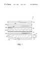
- FIG. 1illustrates a cross-sectional view of a backlighting system.
- FIG. 2illustrates a perspective view of a linear prism structure.
- FIG. 3illustrates a side view of the linear prism structure shown in FIG. 2 .
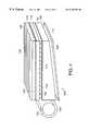
- FIG. 4illustrates a cross-sectional view of a second embodiment of a back lighting system.
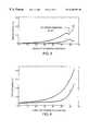
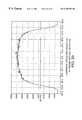
- FIG. 5shows a plot of reflectance as a function of angles of incidence and polarization for a moth-eye structure with 3,300 grooves per millimeter at a light wavelength of 514.5 nm.
- FIG. 6shows a plot of reflectance as a function of angles of incidence and polarization for a moth-eye structure with 3,300 grooves per millimeter at a light wavelength of 647.1 nm.
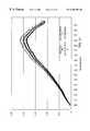
- FIG. 7shows a plot of reflectance for a dielectric having an index of refraction and a smooth non-moth-eye surface.
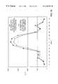
- FIG. 8shows a theoretical plot of output from a uniform light distribution X-profile for one and two films of 0.0019 inch (48 ⁇ m) pitch linear prisms having a prism angle of 90 degrees.
- FIG. 9shows a theoretical plot of output from a uniform light distribution Y-profile for one and two films of 0.0019 inch (48 ⁇ m) pitch linear prisms having a prism angle of 90 degrees.
- FIG. 10shows a theoretical plot of output from a uniform light distribution X-profile for one and two films of 0.0019 inch (48 ⁇ m) pitch linear prisms having a prism angle of 75 and 95 degrees, respectively.
- FIG. 11shows a theoretical plot of output from a uniform light distribution Y-profile for one and two films of 0.0019 inch (48 ⁇ m) pitch linear prisms having a prism angle of 75 and 95 degrees, respectively.
- FIG. 12shows a theoretical plot of output from a uniform light distribution X-profile for one and two films of 0.0019 inch (48 ⁇ m) linear prisms having a prism angle of 75 degrees.
- FIG. 13shows a theoretical plot of output from a uniform light distribution Y-profile for one and two films of 0.0019 inch (48 ⁇ m) linear prisms having a prism angle of 75 degrees.
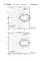
- FIG. 14shows a theoretical plot of output from a cosine light distribution X-profile for one and two films of 0.0019 inch (48 ⁇ m) pitch linear prisms having a prism angle of 90 degrees.
- FIG. 15shows a theoretical plot of output from a cosine light distribution Y-profile for one and two films of 0.0019 inch (48 ⁇ m) pitch linear prisms having a prism angle of 90 degrees.
- FIG. 16shows a theoretical plot of output from a cosine light distribution X-profile for one and two films of 0.0019 inch (48 ⁇ m) pitch linear prisms having a prism angle of 75 and 95 degrees, respectively.
- FIG. 17shows a theoretical plot of output from a cosine light distribution Y-profile for one and two films of 0.0019 inch (48 ⁇ m) pitch linear prisms having a prism angle of 75 and 95 degrees, respectively.
- FIG. 18shows a theoretical plot of output from a cosine light, distribution X-profile for one and two films of 0.0019 inch (48 ⁇ m) linear prisms having a prism angle of 75 degrees.
- FIG. 19shows a theoretical plot of output from a cosine light distribution Y-profile for one and two films of 0.0019 inch (48 ⁇ m) linear prisms having a prism angle of 75 degrees.
- FIG. 20illustrates a side view of a subwavelength optical microstructure.
- FIG. 21shows a plot of relative response versus wavelength of light for a 0.002 inch (51 ⁇ m) thick film of polyester, 0.002 inch (51 ⁇ m) thick film of polyester with one side having moth-eye structures, 0.002 inch (51 ⁇ m) thick film of polyester with two sides having moth-eye structures, and a reference with a detector located normal to the surface of the film.
- FIG. 22shows a plot of relative response versus wavelength of light for a 0.002 inch (51 ⁇ m) thick film of polyester, 0.002 inch (51 ⁇ m) thick film of polyester with one side having moth-eye structures, 0.002 inch (51 ⁇ m) thick films of polyester with two sides having moth-eye structures, and a reference with a detector located at an angle 30 degrees from the normal to the surface of the film.
- FIG. 23shows a plot of light transmission versus angle from the normal of a 0.002 inch (51 ⁇ m) polyester film with and without a moth-eye structure on one side at the zero and 90 degree profile.
- FIG. 24shows a plot of color versus angle from the normal of a 0.002 inch (51 ⁇ m) thick polyester film with and without moth-eye structures on both sides observed at zero degree orientation.
- FIG. 25shows a plot of color versus angle from the normal of a 0.004 inch (102 ⁇ m) thick polyester film with and without moth-eye structures on both sides observed at zero degree X-orientation and 90 degree Y-orientation.
- FIG. 26is a plot of luminance cross section versus observation angle from the normal at zero degree orientation of a film with moth-eye structures having a period of about 0.2 ⁇ m and a height of about 0.4 ⁇ m and linear prisms with 95 degree included angle and a pitch of 0.0019 inch (48 ⁇ m).
- FIG. 27is a plot of luminance cross section versus observation angle from the normal at 90 degrees orientation of a film with moth-eye structures having a period of about 0.2 ⁇ m and a height of about 0.4 ⁇ m and linear prisms with a 95 degree included angle and a pitch of 0.0019 inch (48 ⁇ m).
- FIG. 28is a plot of luminance cross section versus observation angle from the normal at zero degree orientation of a film without moth-eye structures and linear prisms with 95 degree included angle and a pitch of 0.0019 inch (48 ⁇ m).
- FIG. 29is a plot of luminance cross section versus observation angle from the normal at zero degree orientation of a film without moth-eye structures and linear prisms with 95 degree included angle and a pitch of 0.0019 inch (48 ⁇ m).
- FIG. 30shows a plot of light transmission versus angle from the normal of a film with 90 degree linear prisms having a pitch of 0.002 inch (51 ⁇ m) with and without moth-eye structures on the window side of the films.
- a back lighting system 10includes a light source 12 and light reflector 14 .
- Light source 12can be a fluorescent light, incandescent light or other suitable light source.
- Waveguide 16which is for directing light out of back lighting system, can be formed of a transparent solid material and is often wedge shaped.
- waveguide reflector 18On one side of waveguide 16 is waveguide reflector 18 formed of a specular material, such as aluminum or a coated white surface, for reflecting light back to waveguide 16 .
- Waveguide reflector 18can be curved or flat.
- Diffuser 20is a film that diffuses the light from the waveguide into a substantially uniform distribution.
- An example of a suitable diffuseris a randomly textured surface or gradient index film or engineered diffractive structure.
- first collimating film 22has moth-eye structure 24 on a first side adjacent waveguide 16 .
- Second side of first collimating film 22has prism structure 25 .
- An optional abrasion reduction layer 26is between first collimating film 22 and second collimating film 28 .
- the abrasion reduction layercan have a moth-eye structure on one or two surfaces to improve performance.
- Second collimating film 28has moth-eye structure 30 on a first side adjacent first collimating film 22 and prism structure 32 .
- Prism structure 32 of second collimating film 28can be oriented in the same direction as the prisms on first collimating film 22 . Alternatively, it may be offset by rotating the prism orientation up to about 180 degrees.
- the second collimating filmis rotated about 90 degrees with respect to the first collimating film to reduce moire fringe formation.
- a liquid crystal display 34Above the second collimating film is a liquid crystal display 34 .
- a collimating filmwhich has linear prisms designed with a tilt, size and included angle which match the light source, waveguide and diffuser properties provides enhanced performance. The advantages of employing linear prism arrays with included angles which range from 95 degrees to 120 degrees provides a light distribution which is optimized for viewing angles of a computer screen. The included angle is considered the top angle of a triangular linear prism structure.
- Linear prism film 40has prism surface 42 and window surface 44 and is formed of a transparent polymeric material.
- Prisms 46have sides 48 with peaks 50 and valleys 52 .
- the pitch (p) of the prisms 46is measures from valley 52 to next valley 52 .
- the pitchcan be in the range of between 0.001 and 0.003 inches (25 and 76 ⁇ m).
- the height (h) of the linear prismsis measured by the vertical distance from the valley 52 to peak 50 .
- the heightcan be in the range of between 0.0003 and 0.0015 inches (7.6 and 38 ⁇ m).
- the included angle ( ⁇ )is measured between the two sides that meet at peak 50 .
- the angle ( ⁇ )can range from about 60 to 120 degrees. In a preferred embodiment, the angle ( ⁇ ) is in a range of between about 60 and 85 degrees or between about 95 and 120 degrees.
- Sides 42 on each side of the peak 50can be the side length ( 1 ) from valley 52 to peak 50 to form an isosceles triangle. Alternatively, the sides can have different lengths, thereby tilting or canting the prisms.
- the tilting angle ( ⁇ ) of the prismsis between the optical axis 54 and a line 56 perpendicular to the window side 44 .
- the prismscan be tilted in the range of between about ⁇ 44 and +44 degrees. In a preferred embodiment, the tilting is about seven degrees.
- a back lighting system 100includes a light source 102 and a light reflector 104 .
- Waveguide 106can be formed of a transparent solid material and is preferably wedge shaped. Adjacent to the first side 108 of waveguide 106 is waveguide reflector 110 formed of a specular material. The reflector 110 is spaced slightly away from surface 108 to allow total internal reflection at surface 108 to take place. First side 108 can be stepped in shape. Second side 112 of waveguide 106 is on the opposite side away from waveguide reflector 110 . Second side 112 has moth-eye structures 114 .
- first collimating film 116has first prism structure 118 with peaks 120 pointed toward waveguide 106 and first moth-eye structures 122 on the window side of first prism structure 118 .
- the peaks of linear prisms on first collimating film 116run parallel to light source 102 .
- second collimating film 124has second moth-eye structure 126 and second prism structure 128 . Peaks 130 of second prism structure 128 point away from waveguide 106 .
- the peaks 130 of second prism structure 128is oriented in a nonparallel direction to peaks 120 of first prism structure 118 . A more preferred orientation is 90 degrees.
- TIRtotal internally reflecting
- BEFbrightness enhancing film
- BEFrightness enhancing film
- a further improvementcan be made by making the film monolithic or polylithic.
- a monolithic filmremoves one material interface (at the substrate) and improves optical transmission.
- a diffusercan be incorporated into the film structure saving the need to fabricate a separate diffuser and dependent on the degree of collimation required.
- a fine pitch of a linear corner cube prism structureprovides excellent performance as a first layer in a back lighting system if a diffuser is not used between the top smooth surface of a waveguide and a flat surface of the linear micro corner cube sheet.
- a fine pitchpreferably in the range of between about 0.00005 and 0.0001 inches (1.3 and 2.5 ⁇ m), of the corner cube array helps to spread the refracted and retroreflected light by diffraction creating increase diffusion of recycled light.
- the pitchis about 0.000075 inch (1.9 ⁇ m).
- the refracted and retroreflected lightis spread by one to two degrees depending on the accuracy of the linear corner cube array dihedral angles.
- the second linear prism sheetis oriented about 90 degrees with respect to the first sheet.
- the materials that work well for optical microstructured filmsare an ultraviolet cured polymers bonded to a polyester substrate, which can have abrasion resistance which is important during handling of the collimating films. If the prism tips are damaged during handling, the resulting display can have fine lines that appear as less bright than surrounding areas on axis and brighter than surrounding areas off-axis.
- the filmscan be formed of suitable polymers such as polycarbonate.
- the filmscan be constructed from a polycarbonate material, acrylic, or other suitable material, such as disclosed in U.S. Pat. No. 5,396,350, issued to Beeson et al. on Mar. 7, 1995, the teachings of which are incorporated herein by reference.
- An abrasion reduction sheetingsuch as a thin polypropylene film or similar material can be placed in between the collimating film layers to help to reduce any effect from abrasion without losing significant brightness.
- Subwavelength visible light moth-eye structurescan be used on these overleaf films to effectively eliminate Fresnel reflection light losses.
- the softer filmsdo not abrade the linear prism peaks as easily as hard films.
- a semi-soft substratesuch as a polyvinyl chloride film can be used in place of the polyester substrate to make collimating films and reduce abrasion. However, one must be careful of out-gassing and resulting surface contamination which can occur with polyvinyl chloride.
- a linear non-isosceles prism array tilted or canted in the range of between about ⁇ 45 and +45 degrees and preferably at seven degrees, having a 95 degree included angle and a 0.0019 inch (48 ⁇ m) pitch as a first layer and a linear isosceles prism (with zero tilt), having a 95 degree included angle and a 0.0019 inch (48 ⁇ m) pitch as a second layercan significantly improve the amount of light that is directed through an AMLCD to the angles (geometry's) desired for optimum user viewing angles.
- the tilt or canting of the optical axis of the first layer linear prism arraycorrects the skewed direction of the light distribution coming from the waveguide and diffuser.
- a 0.0019 inch (48 ⁇ m) pitchcan cause diffraction spreading, which smooths the light distribution and maximizes the light directed toward the angles most beneficial or desired for a AMLCD display user.
- the 95 degree included anglefurther optimizes the field of view of the light distribution for the display user while still recycling light which is headed in the incorrect direction back into the display where it is used again.
- a preferred collimating film combination for a wedge waveguideincludes a first collimating film which has prisms tilted to correct for the skew created by the waveguide wedge and diffuser layers and has a prism angle designed to maximize the user field of view plus a second collimating film oriented at 90 degrees to the first and with a symmetrical linear prism pattern.
- the prismscan be tilted uniformly in both directions (tilt every other prism in the opposite direction) to have a prism angle that optimizes the user field of view for this axis.
- the diffusercan be made by employing textured films and casting the linear prisms onto the smooth side of the film, by rotary screen printing a diffuse layer onto the polyester tie coat prior to casting the linear prisms onto the diffuse layer (in this embodiment the diffuse layer is sandwiched between the linear prisms and the substrate film), by rotary screen printing a diffuse layer onto a carrier film and then casting linear prisms onto the diffuse layer.
- the prism and diffuse layercan be made of the same material and finish cured together, by adding particles into the tie coat prior to casting the linear prisms onto the tie coat and by dispersing particles in the substrate sheet followed by casting linear prisms onto the substrate sheet.
- the addition of the moth-eye structure to the window side of the collimating filmsincreases the system brightness by about 6% to 8%, which is significantly brighter (by 10% to 12%) than the previously known brightness enhancing film systems with a similar pitch.
- the uniform white lightsuch as a fluorescent bulb which causes this light to have a cool appearance because of the blue shift, has distribution coming from the diffuser which is incident on the first layer moth-eye surface. At angles of incidence of +/ ⁇ 60 degrees., 2% or less of the light is reflected at the first layer moth-eye to air interface.
- Plots of the reflectanceare shown in FIGS. 5 and 6 for a subwavelength microstructure having 3,300 grooves per millimeter of light having wavelengths of 514.5 nm and 647.1 nm, respectively.
- the S linerepresents light perpendicular to the plane of incidence
- the P linerepresents light parallel to the plane of incidence. Shown in FIG.
- the average reflectance(linear average between S and P lines) is about 0.8% at 60 degrees and shown in FIG. 6, the average reflectance is about 2% at 60 degrees. This is compared to an average of about 10% of the light that is reflected at a smooth non-moth-eye surface at a 60 degree angle of incidence.
- FIG. 7shows a plot of an average of about 10% reflectance at a 60 degree incident angle. Also at normal incidence, a typical 4% reflectance due to a smooth surface is reduced to less than 1% with a moth-eye structure.
- a green and then a blue colorcan be observed.
- the coloris a result of diffraction scattering as the short wavelengths enter the moth-eye structure from an angle which causes the aperture of the moth-eye elements to become diffractive.
- This diffraction scattered lightis processed by the linear prism film differently than the light that passes through a non-moth-eye smooth surface.
- the green to blue lightis more uniformly distributed throughout the film creating a more uniform illumination.
- a significant amount of green lightis light piped by total internal reflection within the film and is partially filtered out of the light that becomes available to illuminate an LCD panel.
- Different size (frequency and amplitude) moth-eye structurescan be used to create different illumination effects depending on the light source and optical components used in the illumination system.
- the lightAfter the light has passed through the first moth-eye layer, it is collimated to about 42 degrees and the 95 degree linear prism second surface of the first film layer through refraction collimates the light to approximately +/ ⁇ 30 degrees. Then the light enters the moth-eye surface on the first surface of the second layer film where it is further collimated by refraction. The majority of the light is at +/ ⁇ 30 degrees from the normal as it enters the moth-eye surface and passes through the moth-eye layer with little intensity loss. The light passes through the second layer film and is further redirected through refraction and recycling by the 95 degree linear prism structure. The 95 degree prism shape helps to recycle any of the light that is still traveling at wide angles of incidence. This light eventually emerges from the lighting system within a final +/ ⁇ 29 degree light distribution in both the X and Y axes.
- FIGS. 8 and 9show plots of output uniform light distribution of the X-profile and Y-profile, respectively, for one and two films of 0.0019 inch (48 ⁇ m) pitch for linear prisms having a prism angle of 90 degrees.
- FIGS. 8 and 9show plots of output uniform light distribution of the X-profile and Y-profile, respectively, for one and two films of 0.0019 inch (48 ⁇ m) pitch for linear prisms having a prism angle of 90 degrees.
- FIGS. 10 and 11show plots of output for uniform light distribution X-profile and Y-profile, respectively, for one and two films of 0.0019 inch (48 ⁇ m) pitch for linear prisms having a prism angle of 75 and 95 degrees, respectively.
- FIGS. 12 and 13show plots of output for uniform light distribution X-profile and Y-profile, respectively, for one and two films of 0.0019 inch (48 ⁇ m) linear prisms having a prism angle of 75 degrees.
- FIGS. 14 and 15show plots of output cosine light distribution of the X-profile and Y-profile, respectively, for one and two films of 0.0019 inch (48 ⁇ m) pitch for linear prisms having a prism angle of 90 degrees.
- FIGS. 16 and 17show plots of output for cosine light distribution X-profile and Y-profile, respectively, for one and two films of 0.0019 inch (48 ⁇ m) pitch for linear prisms having a prism angle of 75 and 95 degrees respectively.
- FIGS. 18 and 19show plots of output for cosine light distribution X-profile and Y-profile, respectively, for one and two films of 0.0019 inch (48 ⁇ m) linear prisms having a prism angle of 75 degrees. Additional optimization of the angles allows a near +/ ⁇ 10 degree intensity distribution.
- One disadvantage with this configurationis an approximate +/ ⁇ 2.0 degree void that appears at the center of the light intensity distribution. This effect is visible in FIGS. 12 and 13. Slight curvature or positive-negative canting in the prism facets can reduce this void.
- the application of a moth-eye structure to the smooth surface of the linear prism filmsimproves significantly the light collimating capability of the films by increasing light throughput at the moth-eye structured surface and redirecting wide incident angle light rays. Diffraction effects also play a significant role in the improved performance of the system.
- the resulting color of the backlight assemblyis warmer in appearance than the same assembly without the addition of the moth-eye structures. This color shift can have a beneficial effect on the contrast within the final back light display.
- the moth-eye structure appliedpreferably has an amplitude (A) of about 0.4 micron and a period (P) of less than about 0.2 micron.
- the structureis sinusoidal in appearance and can provide a deep green to deep blue color when viewed at grazing angles of incidence.
- the amplitudeis about three times the period to provide a three to one aspect ratio.
- FIGS. 21 and 22show a plot of the improvement in transmission by wavelength for 0.002 inch (51 ⁇ m) thick PET having moth-eye structures on one side and having moth-eye structures on both sides at zero degrees and at 30 degree angles from the normal, respectively.
- the moth-eye structureshave a period of about 0.2 ⁇ m and a height of about 0.4 ⁇ m.
- the referenceis a uniform light distribution coming from a diffuser positioned above the waveguide.
- FIG. 23shows a plot of the improvement in transmission by angle from the normal for 0.002 inch (51 ⁇ m) PET with moth-eye structures. In this figure, the fluorescent tube light bulb is at a +80 degree position for the 90 degree orientation.
- FIG. 24shows a plot of the color shift which occurs for 0.002 inch (51 ⁇ m) thick PET with moth-eye structures on one side and with moth-eye structures on both sides.
- FIG. 25shows a plot of the color shift that occurs for 0.004 inch (102 ⁇ m) thick PET with 95 degree linear prisms on the side away from the diffuser and with and without moth eye on the side close to the diffuser.
- the sampleswere placed on top of the diffuser in a standard LCD back light assembly and the Photon Research detector, Model PR650 was supported eighteen inches (45.7 cm) above the part surface.
- the moth-eye structureprovides anti-reflection properties to the previously smooth light entrance surface of the substrate even at entrance angles that are near grazing incidence.
- the moth-eye structureis more effective than standard thin film anti-reflection coatings at wide angles of incidence especially angles of incidence beyond 30 degrees up to 80 degrees. This characteristic causes many types of optical microstructure films including linear prism films to process light very differently than the standard linear prism collimating films which have smooth entrance surfaces with or without standard anti-reflection thin film (vacuum deposited or liquid applied) coatings.
- the addition of the moth-eye structureshelps to more efficiently recycle light and also redirects the normally reflected grazing angle incidence rays into the optical microstructure (such as linear prisms) sheet where the rays are refracted, reflected or retroreflected depending on the respective angles of incidence.
- This moth-eye improvement conceptcan be added to many types of brightness enhancement films (BEF).
- BEFbrightness enhancement films
- a moth-eye anti-reflection surfaceis one in which the reflection of light is reduced by the presence of a regular array of small protuberances covering the surface. The spacing of the protuberances is less than the wavelength of light for which anti-reflection is sought.
- a moth-eye surfacecan be understood in terms of a surface layer in which the refractive index varies gradually from unity to that of the bulk material. Without such a layer the Fresnel reflection coefficient at an interface of two media is equal to ((n 1 ⁇ n 2 )/(n 1 +n 2 )) 2 , where n 1 and n 2 are the refractive indices of the media.
- net reflectancecan be regarded as the result of an infinite series of reflections at each incremental change in index. Since each reflection comes from a different depth from the surface, each has a different phase. If a transition takes place over an optical distance of ⁇ /2, all phases are present, there is destructive interference and the reflectance falls to zero.
- the interfaceappears relatively sharp and the reflectance is essentially that of a discontinuous boundary.
- Further increases in h/ ⁇show a series of successive maxima and minima, but the value does not again approach that of a sharp interface.
- the details of the curve shown in FIG. 20vary depending on the profile of the change of the index of refraction, but if the thickness is of the order of half a wavelength or more the reflectance is considerably reduced.
- the spacing of the protuberancesshould be sufficiently fine to avoid losses by diffraction. Preferably, it should be less than the shortest wavelength involved divided by the refractive index of the material.
- the arraycan act as a diffraction grating and, although there may well be a reduction in the specular reflection (zero order), the light is simply redistributed into the diffracted orders.
- d ⁇ for normal incidence and d ⁇ /2 for oblique incidence if for reflection onlyand that d ⁇ /2n in the case of transmission where diffraction inside the material is suppressed.
- the reflectanceis expected to be very low for wavelengths less than about 2.5 h and greater than d at normal incidence, and for wavelengths greater than 2d for oblique incidence.
- the spacingis as close as possible, and the depth as great as possible, in order to give the widest possible bandwidth.
- a h/d ratiois preferably about three.
- the moth-eye effectshould not be confused with that of reducing the specular reflectance by roughening. Roughness merely redistributes the reflected light as diffuse scattering and degrades the transmitted wavefront. With the moth-eye structure, there is no increase in diffuse scattering, the transmitted wavefront is not degraded and the reduction in reflection gives rise to a corresponding increase in transmission.
- the moth-eye structurehas many advantages. There is no extra coating process necessary.
- the structurecan be transferred to the sheet by a pressure molding process, such as with a Fresnel structure.
- the reflection reductiondoes not depend on the wavelength. There is only a lower limit (on the ultraviolet side of the spectrum) set by the structure period. If the wavelength is too small compared to the period, the light is diffracted. In regard to angular dependence, with conventional anti-reflective coatings, the transmission curve shifts with the light incidence angle. With the moth-eye structure, the critical wavelength for diffraction shifts to higher values, but there are no changes above this wavelength.
- Another advantage for moth-eye structuresis that there are no adhesion problems between lens and gradient layer because it can be one bulk material. From a high incident angle, the surfaces can appear blue or violet.
- the structureis first produced on a photoresist-covered glass substrate by a holographic exposure using an ultraviolet laser.
- a suitable deviceis available from Holographic Lithography Systems of Bedford, Mass. 01730.
- An example of a methodis disclosed in U.S. Pat. No. 4,013,465, issued to Clapham et al on Mar. 22, 1977, the teachings of which are incorporated herein by reference. This method is sensitive to any changes in the environment, such as temperature and dust, and care must taken.
- the structureis then transferred to a nickel shim by an electroforming process. In a preferred embodiment, the shims are about 300 microns thick or less.
- the moth-eye structurescan be made one dimensional in a grating type pattern.
- the structurehas a nearly rectangular profile, which means they have no gradient layers, but more of a one layer anti-reflective coating with a lowered refractive index in the structure region.
- Control of the grating depthis important as is control of thickness for the evaporated layers. Control of depth and thickness is achieved by maintaining uniformity of beam exposure, substrate flatness and exposure time.
- a two-dimensional structureis formed by two exposures with a linear sinus-grid, turned by 90 degrees for the second exposure.
- a third type of structureis formed by three exposures with turns of 60 degrees to provide a hexagonal or honeycomb shape.
- the results with two 95 degree linear prism films each having a moth-eye structure on the previously smooth sideshow about the same brightness on axis as two 90 degree BEF films, a large improvement in brightness off axis in both vertical and horizontal axis and a warmer color to the light emerging from the display.
- the total integrated light intensity for the 95 degree prisms with moth-eye structure filmsis 6,686.8 lm/m 2 with a maximum of 4,460 cd/m 2 and a minimum of 554.0 cd/m 2 .
- the integrated light intensityis 5,698.8 lm/m 2 with a maximum of 4,685.0 cd/m 2 and a minimum of 295.9 cd/m 2 .
- a preferred embodimentincludes a 75 degree linear prism film can be used as the first layer above a uniform light output diffuser to collimate the light to about a +/ ⁇ 30 degree angle.
- the prism grooves in this first layerare oriented parallel to the light source that illuminates the waveguide which is below the diffuser.
- On top of this filmcan be a 95 degree linear prism film which is oriented at 90 degrees with respect to the 75 degree film to collimate the light to about +/ ⁇ 25 degrees with a small percentage of the light at +/ ⁇ 30 degrees as shown in FIGS. 10, 11 , 16 and 17 .
- the final intensity of the collimated lightis excellent and comparable to results obtained with two crossed 90 degrees BEF films, as shown in FIGS. 8, 9 , 14 and 15 .
- the prism apex angle of the second 95 degree filmcan be increased to about 100 degrees if the spread in the collimated light beam is too narrow.
- FIG. 30shows a comparative plot of light transmission versus angle from the normal of a film with 90 degree linear prisms having a pitch of 0.002 inch (51 ⁇ m) with moth-eye structures on the window side of the film and a film with 90 degree linear prisms having a pitch of 0.002 inch (51 ⁇ m) without moth-eye structures on the side of the film.
- the comparative plotshows a substantial improvement in transmission, particularly at zero degrees, when employing a moth-eye structure on the window side of the film as compared to a similar film without a moth-eye structure.
Landscapes
- Physics & Mathematics (AREA)
- General Physics & Mathematics (AREA)
- Optics & Photonics (AREA)
- Optical Elements Other Than Lenses (AREA)
Abstract
Description
Claims (15)
Priority Applications (7)
| Application Number | Priority Date | Filing Date | Title |
|---|---|---|---|
| US09/438,912US6356389B1 (en) | 1999-11-12 | 1999-11-12 | Subwavelength optical microstructure light collimating films |
| US09/684,455US6570710B1 (en) | 1999-11-12 | 2000-10-06 | Subwavelength optical microstructure light collimating films |
| CNB008156115ACN1278139C (en) | 1999-11-12 | 2000-11-08 | Subwavelength Optical Microstructured Light Alignment Film |
| EP00990498AEP1248958A2 (en) | 1999-11-12 | 2000-11-08 | Subwavelength optical microstructure light collimating films |
| PCT/US2000/042002WO2001035128A2 (en) | 1999-11-12 | 2000-11-08 | Subwavelength optical microstructure light collimating films |
| JP2001536603AJP2003518263A (en) | 1999-11-12 | 2000-11-08 | Optical collimation film with submicroscopic optical microstructure |
| US10/445,375US6891677B2 (en) | 1999-11-12 | 2003-05-23 | Subwavelength optical microstructure light-redirecting films |
Applications Claiming Priority (1)
| Application Number | Priority Date | Filing Date | Title |
|---|---|---|---|
| US09/438,912US6356389B1 (en) | 1999-11-12 | 1999-11-12 | Subwavelength optical microstructure light collimating films |
Related Child Applications (1)
| Application Number | Title | Priority Date | Filing Date |
|---|---|---|---|
| US09/684,455Continuation-In-PartUS6570710B1 (en) | 1999-11-12 | 2000-10-06 | Subwavelength optical microstructure light collimating films |
Publications (1)
| Publication Number | Publication Date |
|---|---|
| US6356389B1true US6356389B1 (en) | 2002-03-12 |
Family
ID=23742541
Family Applications (1)
| Application Number | Title | Priority Date | Filing Date |
|---|---|---|---|
| US09/438,912Expired - Fee RelatedUS6356389B1 (en) | 1999-11-12 | 1999-11-12 | Subwavelength optical microstructure light collimating films |
Country Status (1)
| Country | Link |
|---|---|
| US (1) | US6356389B1 (en) |
Cited By (85)
| Publication number | Priority date | Publication date | Assignee | Title |
|---|---|---|---|---|
| US20020051866A1 (en)* | 2000-08-18 | 2002-05-02 | Reflexite Corporation | Differentially cured materials and process for forming same |
| US20020135825A1 (en)* | 2000-07-14 | 2002-09-26 | Chih-Kung Lee | High light-sensing efficiency image sensor apparatus and method |
| US20030081197A1 (en)* | 2001-08-06 | 2003-05-01 | Zoladz Edward M. | Document validator subassembly |
| US6749313B2 (en)* | 2002-01-17 | 2004-06-15 | Ludwig Leuchten Kg | Plate-type luminaire |
| US6759965B1 (en)* | 1999-05-28 | 2004-07-06 | Oy Ics Intelligent Control Systems Ltd | Light indicator |
| US20040164946A1 (en)* | 2003-02-21 | 2004-08-26 | Cavanaugh Shanti A. | Thermal control system for liquid crystal cell |
| US20040165131A1 (en)* | 2003-02-21 | 2004-08-26 | Anderson Grady K. | Fabrication method for liquid crystal cell |
| US20040165139A1 (en)* | 2003-02-21 | 2004-08-26 | Anderson Grady K. | Liquid crystal cell platform |
| US20040169791A1 (en)* | 2000-08-15 | 2004-09-02 | Reflexite Corporation | Light polarizer |
| US20040190102A1 (en)* | 2000-08-18 | 2004-09-30 | Mullen Patrick W. | Differentially-cured materials and process for forming same |
| US20040239869A1 (en)* | 2003-06-02 | 2004-12-02 | Cavanaugh Shanti A. | Narrow band tunable filter with integrated detector |
| US20040246599A1 (en)* | 2003-05-02 | 2004-12-09 | Reflexite Corporation | Light-redirecting optical structures |
| US20050024554A1 (en)* | 2000-06-07 | 2005-02-03 | Lee Jeong-Hwan | Method for illuminating liquid crystal display device, a back-light assembly for performing the same, and a liquid crystal display device using the same |
| US20050094277A1 (en)* | 2003-10-30 | 2005-05-05 | Niyaz Khusnatdinov | Microtextured antireflective surfaces with reduced diffraction intensity |
| US20050141243A1 (en)* | 2000-08-18 | 2005-06-30 | Reflexite Corporation | Differentially-cured materials and process for forming same |
| US20050270766A1 (en)* | 2004-06-08 | 2005-12-08 | Prodisc Technology Inc. | Liquid crystal display device and backlight module thereof |
| US20060007386A1 (en)* | 2003-02-21 | 2006-01-12 | Extellus Usa | Flat top tunable filter with integrated detector |
| US20060050533A1 (en)* | 2004-09-03 | 2006-03-09 | Industrial Technology Research Institute | Direct backlight modules |
| US7030944B2 (en)* | 1998-12-14 | 2006-04-18 | Nec Lcd Technologies, Ltd. | Liquid crystal display device with roughened surfaces to reduce moiré fringe effects |
| US20060113279A1 (en)* | 2004-11-30 | 2006-06-01 | Little Michael J | Non-photolithographic method for forming a wire grid polarizer for optical and infrared wavelengths |
| US20060118514A1 (en)* | 2004-11-30 | 2006-06-08 | Agoura Technologies, Inc. | Applications and fabrication techniques for large scale wire grid polarizers |
| US20060139956A1 (en)* | 2004-12-24 | 2006-06-29 | Lg.Philips Lcd Co., Ltd. | Display device and backlight unit for the same |
| WO2006095161A2 (en) | 2005-03-10 | 2006-09-14 | De La Rue International Limited | Article and security device based on customised microprism film |
| US20060238874A1 (en)* | 2005-04-22 | 2006-10-26 | Industrial Technology Research Institute | Light modulation element |
| US20070030415A1 (en)* | 2005-05-16 | 2007-02-08 | Epstein Kenneth A | Back-lit displays with high illumination uniformity |
| US20070058920A1 (en)* | 2005-09-13 | 2007-03-15 | Efun Technology Co., Ltd. | Brightness enhancement film having a light-guiding structure |
| WO2007040725A1 (en)* | 2005-09-26 | 2007-04-12 | Avery Dennison Corporation | Retroreflective sheeting comprising a divergence enhancing layer |
| US20070116934A1 (en)* | 2005-11-22 | 2007-05-24 | Miller Scott M | Antireflective surfaces, methods of manufacture thereof and articles comprising the same |
| US20070115569A1 (en)* | 2004-07-02 | 2007-05-24 | Efun Technology Co., Ltd. | Brightness enhancement film having curved prism units and microstructure layer |
| US20070139776A1 (en)* | 2005-12-16 | 2007-06-21 | Innolux Display Corp. | Brightness enhancement film with protective layer and backlight module and liquid crystal display with same |
| US20070263411A1 (en)* | 1998-12-29 | 2007-11-15 | Franz Schellhorn | Light Source Element with Lateral, Oblique Light Infeed |
| US20070263412A1 (en)* | 2006-05-09 | 2007-11-15 | Lg Electronics Inc. | Prism sheet, backlight unit and liquid crystal display |
| US20070279773A1 (en)* | 2006-05-31 | 2007-12-06 | 3M Innovative Properties Company | Light directing film |
| US20080025687A1 (en)* | 2006-07-04 | 2008-01-31 | Dong Ho Lee | Light guide member and backlight unit including light guide member |
| US20080101759A1 (en)* | 2006-10-26 | 2008-05-01 | K Laser Technology, Inc. | Prism matrix with random phase structures |
| US20080111945A1 (en)* | 2006-11-15 | 2008-05-15 | 3M Innovative Properties Company | Back-lit displays with high illumination uniformity |
| US20080111948A1 (en)* | 2006-11-15 | 2008-05-15 | 3M Innovative Properties Company | Back-lit displays with high illumination uniformity |
| US20080129930A1 (en)* | 2006-12-01 | 2008-06-05 | Agoura Technologies | Reflective polarizer configuration for liquid crystal displays |
| US20080266389A1 (en)* | 2000-03-02 | 2008-10-30 | Donnelly Corporation | Vehicular video mirror system |
| US20090015736A1 (en)* | 2005-11-01 | 2009-01-15 | Donnelly Corporation | Interior rearview mirror assembly with display |
| US20090067032A1 (en)* | 1994-05-05 | 2009-03-12 | Donnelly Corporation | Vehicular signal mirror |
| GB2454928A (en)* | 2007-11-23 | 2009-05-27 | Iti Scotland Ltd | Light guides |
| US20090243824A1 (en)* | 2008-03-31 | 2009-10-01 | Magna Mirrors Of America, Inc. | Interior rearview mirror system |
| US20090279280A1 (en)* | 2004-12-16 | 2009-11-12 | David John Bottomley | Structured optical film |
| US20090286346A1 (en)* | 2008-05-14 | 2009-11-19 | International Business Machines Corporation | Methods For Forming Anti-Reflection Structures For CMOS Image Sensors |
| US20090283807A1 (en)* | 2008-05-14 | 2009-11-19 | International Business Machines Corporation | Anti-Reflection Structures For CMOS Image Sensors |
| US20100019155A1 (en)* | 2005-06-23 | 2010-01-28 | Koninklijke Philips Electronics, N.V. | Luminescence sensors using sub-wavelength apertures or slits |
| US20100045790A1 (en)* | 2001-01-23 | 2010-02-25 | Donnelly Corporation | Video mirror system for vehicle |
| US20100053723A1 (en)* | 1994-05-05 | 2010-03-04 | Donnelly Corporation | Exterior reflective mirror element for a vehicular rearview mirror assembly |
| US20100067223A1 (en)* | 2008-09-18 | 2010-03-18 | Guardian Industries Corp. | Lighting system cover including AR-coated textured glass, and method of making the same |
| US20100135004A1 (en)* | 2006-11-15 | 2010-06-03 | Epstein Kenneth A | Back-lit displays with high illumination uniformity |
| US7789538B2 (en) | 2006-11-15 | 2010-09-07 | 3M Innovative Properties Company | Back-lit displays with high illumination uniformity |
| US20100244169A1 (en)* | 2009-03-31 | 2010-09-30 | Sony Corporation | Solid-state imaging device, fabrication method thereof, imaging apparatus, and fabrication method of anti-reflection structure |
| US7815326B2 (en) | 2002-06-06 | 2010-10-19 | Donnelly Corporation | Interior rearview mirror system |
| US7822543B2 (en) | 2000-03-02 | 2010-10-26 | Donnelly Corporation | Video display system for vehicle |
| US7826123B2 (en) | 2002-09-20 | 2010-11-02 | Donnelly Corporation | Vehicular interior electrochromic rearview mirror assembly |
| US7832882B2 (en) | 2002-06-06 | 2010-11-16 | Donnelly Corporation | Information mirror system |
| US7859737B2 (en) | 2002-09-20 | 2010-12-28 | Donnelly Corporation | Interior rearview mirror system for a vehicle |
| US7864399B2 (en) | 2002-09-20 | 2011-01-04 | Donnelly Corporation | Reflective mirror assembly |
| US7888629B2 (en) | 1998-01-07 | 2011-02-15 | Donnelly Corporation | Vehicular accessory mounting system with a forwardly-viewing camera |
| US20110043742A1 (en)* | 2003-02-21 | 2011-02-24 | Cavanaugh Shanti A | Contamination prevention in liquid crystal cells |
| US7898398B2 (en) | 1997-08-25 | 2011-03-01 | Donnelly Corporation | Interior mirror system |
| US7898719B2 (en) | 2003-10-02 | 2011-03-01 | Donnelly Corporation | Rearview mirror assembly for vehicle |
| US7906756B2 (en) | 2002-05-03 | 2011-03-15 | Donnelly Corporation | Vehicle rearview mirror system |
| US7916009B2 (en) | 1998-01-07 | 2011-03-29 | Donnelly Corporation | Accessory mounting system suitable for use in a vehicle |
| US7914188B2 (en) | 1997-08-25 | 2011-03-29 | Donnelly Corporation | Interior rearview mirror system for a vehicle |
| US7926960B2 (en) | 1999-11-24 | 2011-04-19 | Donnelly Corporation | Interior rearview mirror system for vehicle |
| US8019505B2 (en) | 2003-10-14 | 2011-09-13 | Donnelly Corporation | Vehicle information display |
| US20110234941A1 (en)* | 2008-10-21 | 2011-09-29 | James Gourlay | Light guides |
| US8044776B2 (en) | 2000-03-02 | 2011-10-25 | Donnelly Corporation | Rear vision system for vehicle |
| US8049640B2 (en) | 2003-05-19 | 2011-11-01 | Donnelly Corporation | Mirror assembly for vehicle |
| US8083386B2 (en) | 2001-01-23 | 2011-12-27 | Donnelly Corporation | Interior rearview mirror assembly with display device |
| US8288711B2 (en) | 1998-01-07 | 2012-10-16 | Donnelly Corporation | Interior rearview mirror system with forwardly-viewing camera and a control |
| US8294975B2 (en) | 1997-08-25 | 2012-10-23 | Donnelly Corporation | Automotive rearview mirror assembly |
| US8462204B2 (en) | 1995-05-22 | 2013-06-11 | Donnelly Corporation | Vehicular vision system |
| US8503062B2 (en) | 2005-05-16 | 2013-08-06 | Donnelly Corporation | Rearview mirror element assembly for vehicle |
| US8525703B2 (en) | 1998-04-08 | 2013-09-03 | Donnelly Corporation | Interior rearview mirror system |
| US8727593B2 (en) | 2012-06-14 | 2014-05-20 | Apple Inc. | Displays with rounded-tip turning films |
| US9019091B2 (en) | 1999-11-24 | 2015-04-28 | Donnelly Corporation | Interior rearview mirror system |
| US9164223B2 (en) | 2009-03-05 | 2015-10-20 | Iti Scotland Limited | Light guides |
| US9164214B2 (en) | 2013-07-30 | 2015-10-20 | Nicklas Benton Tininenko | Multicolor film |
| US9487144B2 (en) | 2008-10-16 | 2016-11-08 | Magna Mirrors Of America, Inc. | Interior mirror assembly with display |
| US9625641B2 (en) | 2009-03-05 | 2017-04-18 | Design Led Products Limited | Light guides |
| US11122191B2 (en)* | 2019-11-04 | 2021-09-14 | Samsung Electro-Mechanics Co., Ltd. | Camera module and portable terminal |
| US11163102B2 (en)* | 2018-11-23 | 2021-11-02 | Innolux Corporation | Backlight module and light guide plate thereof and display device using the same |
Citations (58)
| Publication number | Priority date | Publication date | Assignee | Title |
|---|---|---|---|---|
| GB198279A (en) | 1922-09-23 | 1923-05-31 | Alfred Cave | Improvements in or relating to apparatus for use in cutting cheese and other plastic or semi-solid substances |
| US2218227A (en) | 1938-04-02 | 1940-10-15 | Douglas F Winnek | Method for embossing sheet plastic material |
| US2232551A (en) | 1936-01-10 | 1941-02-18 | Merton Thomas Ralph | Method of preparing diffractive foils and other bodies with diffractive surfaces |
| US2248638A (en) | 1937-02-22 | 1941-07-08 | Merton Thomas Ralph | Sheet material with prismatic surfaces |
| US2310790A (en) | 1943-02-09 | Optical reflecting material | ||
| US2474317A (en) | 1949-06-28 | Light refracting and transmitting | ||
| US3234376A (en) | 1963-02-11 | 1966-02-08 | Michael J Ceglia | Glare-free lighting fixture |
| US3288990A (en) | 1964-09-25 | 1966-11-29 | K S H Plastics Inc | Panel |
| US3846012A (en) | 1973-11-14 | 1974-11-05 | Qantix Corp | Transparent front projection screen having concave ridges thereon |
| US3908056A (en) | 1973-09-10 | 1975-09-23 | Minnesota Mining & Mfg | Optically decorative web |
| US4013465A (en) | 1973-05-10 | 1977-03-22 | Secretary Of State For Defence In Her Britannic Majesty's Government Of The United Kingdom Of Great Britain And Northern Ireland | Reducing the reflectance of surfaces to radiation |
| US4064433A (en) | 1976-06-30 | 1977-12-20 | K-S-H, Inc. | Prismatic lighting panel |
| US4114983A (en) | 1977-02-18 | 1978-09-19 | Minnesota Mining And Manufacturing Company | Polymeric optical element having antireflecting surface |
| US4120565A (en) | 1977-06-16 | 1978-10-17 | The United States Of America As Represented By The United States Department Of Energy | Prisms with total internal reflection as solar reflectors |
| GB1529021A (en) | 1977-03-24 | 1978-10-18 | Secretary Industry Brit | Double glazed windows |
| US4154219A (en) | 1977-03-11 | 1979-05-15 | E-Systems, Inc. | Prismatic solar reflector apparatus and method of solar tracking |
| US4233651A (en) | 1978-03-30 | 1980-11-11 | Keene Corporation | Work area lighting system |
| US4242723A (en) | 1979-05-14 | 1980-12-30 | Keene Corporation | Low level work area lighting system |
| US4260220A (en) | 1979-06-15 | 1981-04-07 | Canadian Patents And Development Limited | Prism light guide having surfaces which are in octature |
| US4340276A (en) | 1978-11-01 | 1982-07-20 | Minnesota Mining And Manufacturing Company | Method of producing a microstructured surface and the article produced thereby |
| US4414316A (en) | 1980-09-05 | 1983-11-08 | Rexham Corporation | Composite lenticular screen sheet |
| US4420502A (en) | 1980-09-05 | 1983-12-13 | Conley Kenneth E | Apparatus and method for producing a flexible sheet material having a predetermined surface characteristic |
| US4497860A (en) | 1978-12-18 | 1985-02-05 | Minnesota Mining And Manufacturing Company | Imageable prismatic array |
| US4542449A (en) | 1983-08-29 | 1985-09-17 | Canadian Patents & Development Limited | Lighting panel with opposed 45° corrugations |
| US4576850A (en) | 1978-07-20 | 1986-03-18 | Minnesota Mining And Manufacturing Company | Shaped plastic articles having replicated microstructure surfaces |
| US4615579A (en) | 1983-08-29 | 1986-10-07 | Canadian Patents & Development Ltd. | Prism light guide luminaire |
| US4668558A (en) | 1978-07-20 | 1987-05-26 | Minnesota Mining And Manufacturing Company | Shaped plastic articles having replicated microstructure surfaces |
| US4787708A (en) | 1987-05-08 | 1988-11-29 | Tir Systems Ltd. | Apparatus for continuously controlled emission of light from prism light guide |
| US4805984A (en) | 1985-11-21 | 1989-02-21 | Minnesota Mining And Manufacturing Company | Totally internally reflecting light conduit |
| US4883341A (en) | 1987-04-24 | 1989-11-28 | Tir Systems Ltd | Non-reflective graphic surface |
| US4906070A (en) | 1985-11-21 | 1990-03-06 | Minnesota Mining And Manufacturing Company | Totally internally reflecting thin, flexible film |
| EP0414313A1 (en) | 1989-08-22 | 1991-02-27 | Koninklijke Philips Electronics N.V. | Rear projection screen and rear projection system comprising such a screen |
| US5056892A (en) | 1985-11-21 | 1991-10-15 | Minnesota Mining And Manufacturing Company | Totally internally reflecting thin, flexible film |
| US5126882A (en) | 1987-11-12 | 1992-06-30 | Mitsubishi Rayon Co., Ltd. | Plane light source unit |
| US5183597A (en) | 1989-02-10 | 1993-02-02 | Minnesota Mining And Manufacturing Company | Method of molding microstructure bearing composite plastic articles |
| US5186530A (en) | 1991-11-22 | 1993-02-16 | Tir Systems, Ltd. | Lighting structure having variable transmissivity internal light guide illumination |
| EP0685681A2 (en) | 1994-05-31 | 1995-12-06 | SANYO ELECTRIC Co., Ltd. | Solar lighting apparatus and controller for said apparatus |
| WO1996010148A1 (en) | 1994-09-27 | 1996-04-04 | Minnesota Mining And Manufacturing Company | Luminance control film |
| US5592332A (en) | 1992-12-25 | 1997-01-07 | Dai Nippon Printing Co., Ltd. | Renticular lens, surface light source, and liquid crystal display apparatus |
| US5600462A (en) | 1992-09-16 | 1997-02-04 | International Business Machines Corporation | Optical film and liquid crystal display device using the film |
| WO1997028468A1 (en) | 1996-02-05 | 1997-08-07 | Minnesota Mining And Manufacturing Company | Brightness enhancement film with soft cutoff |
| US5716681A (en) | 1995-02-03 | 1998-02-10 | Minnesota Mining And Manufacturing Company | Scratch resistant optical films and methods for producing same |
| US5760960A (en)* | 1995-05-19 | 1998-06-02 | Cornell Research Foundation, Inc. | Cascaded self-induced holography |
| US5771328A (en) | 1995-03-03 | 1998-06-23 | Minnesota Mining And Manufacturing Company | Light directing film having variable height structured surface and light directing article constructed therefrom |
| WO1998033006A2 (en) | 1997-01-13 | 1998-07-30 | Minnesota Mining And Manufacturing Company | Luminaire device |
| US5812319A (en)* | 1995-10-31 | 1998-09-22 | The United States Of America As Represented By The Secretary Of The Army | Sacrificial micro-gratings |
| WO1998050805A1 (en) | 1997-05-09 | 1998-11-12 | Minnesota Mining And Manufacturing Company | Optical product prepared from high index of refraction brominated monomers |
| US5838404A (en) | 1994-03-01 | 1998-11-17 | Asahi Glass Company Ltd. | Display device with optical member having two parts in overlay relation to reflect light incident at particular angle |
| US5844720A (en) | 1995-09-08 | 1998-12-01 | Goyo Paper Working Co., Ltd. | Prism sheet |
| US5854872A (en)* | 1996-10-08 | 1998-12-29 | Clio Technologies, Inc. | Divergent angle rotator system and method for collimating light beams |
| US5919551A (en) | 1996-04-12 | 1999-07-06 | 3M Innovative Properties Company | Variable pitch structured optical film |
| US5940149A (en) | 1997-12-11 | 1999-08-17 | Minnesota Mining And Manufacturing Company | Planar polarizer for LCD projectors |
| WO1999050691A1 (en) | 1998-03-27 | 1999-10-07 | Fresnel Optics Gmbh | Optically active element and method for the production thereof |
| US5999685A (en)* | 1997-02-07 | 1999-12-07 | Sanyo Electric Co., Ltd. | Light guide plate and surface light source using the light guide plate |
| US6049649A (en)* | 1996-03-28 | 2000-04-11 | Enplas Corporation | Surface light source device of side-light type |
| US6104854A (en)* | 1996-03-29 | 2000-08-15 | Enplas Corporation | Light regulator and surface light source device |
| WO2000052527A1 (en) | 1999-03-01 | 2000-09-08 | Fresnel Optics, Inc. | An optical element screen |
| US6151166A (en)* | 1997-05-22 | 2000-11-21 | Omron Corporation | Color separation element and image display device using same |
- 1999
- 1999-11-12USUS09/438,912patent/US6356389B1/ennot_activeExpired - Fee Related
Patent Citations (58)
| Publication number | Priority date | Publication date | Assignee | Title |
|---|---|---|---|---|
| US2310790A (en) | 1943-02-09 | Optical reflecting material | ||
| US2474317A (en) | 1949-06-28 | Light refracting and transmitting | ||
| GB198279A (en) | 1922-09-23 | 1923-05-31 | Alfred Cave | Improvements in or relating to apparatus for use in cutting cheese and other plastic or semi-solid substances |
| US2232551A (en) | 1936-01-10 | 1941-02-18 | Merton Thomas Ralph | Method of preparing diffractive foils and other bodies with diffractive surfaces |
| US2248638A (en) | 1937-02-22 | 1941-07-08 | Merton Thomas Ralph | Sheet material with prismatic surfaces |
| US2218227A (en) | 1938-04-02 | 1940-10-15 | Douglas F Winnek | Method for embossing sheet plastic material |
| US3234376A (en) | 1963-02-11 | 1966-02-08 | Michael J Ceglia | Glare-free lighting fixture |
| US3288990A (en) | 1964-09-25 | 1966-11-29 | K S H Plastics Inc | Panel |
| US4013465A (en) | 1973-05-10 | 1977-03-22 | Secretary Of State For Defence In Her Britannic Majesty's Government Of The United Kingdom Of Great Britain And Northern Ireland | Reducing the reflectance of surfaces to radiation |
| US3908056A (en) | 1973-09-10 | 1975-09-23 | Minnesota Mining & Mfg | Optically decorative web |
| US3846012A (en) | 1973-11-14 | 1974-11-05 | Qantix Corp | Transparent front projection screen having concave ridges thereon |
| US4064433A (en) | 1976-06-30 | 1977-12-20 | K-S-H, Inc. | Prismatic lighting panel |
| US4114983A (en) | 1977-02-18 | 1978-09-19 | Minnesota Mining And Manufacturing Company | Polymeric optical element having antireflecting surface |
| US4154219A (en) | 1977-03-11 | 1979-05-15 | E-Systems, Inc. | Prismatic solar reflector apparatus and method of solar tracking |
| GB1529021A (en) | 1977-03-24 | 1978-10-18 | Secretary Industry Brit | Double glazed windows |
| US4120565A (en) | 1977-06-16 | 1978-10-17 | The United States Of America As Represented By The United States Department Of Energy | Prisms with total internal reflection as solar reflectors |
| US4233651A (en) | 1978-03-30 | 1980-11-11 | Keene Corporation | Work area lighting system |
| US4668558A (en) | 1978-07-20 | 1987-05-26 | Minnesota Mining And Manufacturing Company | Shaped plastic articles having replicated microstructure surfaces |
| US4576850A (en) | 1978-07-20 | 1986-03-18 | Minnesota Mining And Manufacturing Company | Shaped plastic articles having replicated microstructure surfaces |
| US4340276A (en) | 1978-11-01 | 1982-07-20 | Minnesota Mining And Manufacturing Company | Method of producing a microstructured surface and the article produced thereby |
| US4497860A (en) | 1978-12-18 | 1985-02-05 | Minnesota Mining And Manufacturing Company | Imageable prismatic array |
| US4242723A (en) | 1979-05-14 | 1980-12-30 | Keene Corporation | Low level work area lighting system |
| US4260220A (en) | 1979-06-15 | 1981-04-07 | Canadian Patents And Development Limited | Prism light guide having surfaces which are in octature |
| US4420502A (en) | 1980-09-05 | 1983-12-13 | Conley Kenneth E | Apparatus and method for producing a flexible sheet material having a predetermined surface characteristic |
| US4414316A (en) | 1980-09-05 | 1983-11-08 | Rexham Corporation | Composite lenticular screen sheet |
| US4542449A (en) | 1983-08-29 | 1985-09-17 | Canadian Patents & Development Limited | Lighting panel with opposed 45° corrugations |
| US4615579A (en) | 1983-08-29 | 1986-10-07 | Canadian Patents & Development Ltd. | Prism light guide luminaire |
| US5056892A (en) | 1985-11-21 | 1991-10-15 | Minnesota Mining And Manufacturing Company | Totally internally reflecting thin, flexible film |
| US4805984A (en) | 1985-11-21 | 1989-02-21 | Minnesota Mining And Manufacturing Company | Totally internally reflecting light conduit |
| US4906070A (en) | 1985-11-21 | 1990-03-06 | Minnesota Mining And Manufacturing Company | Totally internally reflecting thin, flexible film |
| US4883341A (en) | 1987-04-24 | 1989-11-28 | Tir Systems Ltd | Non-reflective graphic surface |
| US4787708A (en) | 1987-05-08 | 1988-11-29 | Tir Systems Ltd. | Apparatus for continuously controlled emission of light from prism light guide |
| US5126882A (en) | 1987-11-12 | 1992-06-30 | Mitsubishi Rayon Co., Ltd. | Plane light source unit |
| US5183597A (en) | 1989-02-10 | 1993-02-02 | Minnesota Mining And Manufacturing Company | Method of molding microstructure bearing composite plastic articles |
| EP0414313A1 (en) | 1989-08-22 | 1991-02-27 | Koninklijke Philips Electronics N.V. | Rear projection screen and rear projection system comprising such a screen |
| US5186530A (en) | 1991-11-22 | 1993-02-16 | Tir Systems, Ltd. | Lighting structure having variable transmissivity internal light guide illumination |
| US5600462A (en) | 1992-09-16 | 1997-02-04 | International Business Machines Corporation | Optical film and liquid crystal display device using the film |
| US5592332A (en) | 1992-12-25 | 1997-01-07 | Dai Nippon Printing Co., Ltd. | Renticular lens, surface light source, and liquid crystal display apparatus |
| US5838404A (en) | 1994-03-01 | 1998-11-17 | Asahi Glass Company Ltd. | Display device with optical member having two parts in overlay relation to reflect light incident at particular angle |
| EP0685681A2 (en) | 1994-05-31 | 1995-12-06 | SANYO ELECTRIC Co., Ltd. | Solar lighting apparatus and controller for said apparatus |
| WO1996010148A1 (en) | 1994-09-27 | 1996-04-04 | Minnesota Mining And Manufacturing Company | Luminance control film |
| US5716681A (en) | 1995-02-03 | 1998-02-10 | Minnesota Mining And Manufacturing Company | Scratch resistant optical films and methods for producing same |
| US5771328A (en) | 1995-03-03 | 1998-06-23 | Minnesota Mining And Manufacturing Company | Light directing film having variable height structured surface and light directing article constructed therefrom |
| US5760960A (en)* | 1995-05-19 | 1998-06-02 | Cornell Research Foundation, Inc. | Cascaded self-induced holography |
| US5844720A (en) | 1995-09-08 | 1998-12-01 | Goyo Paper Working Co., Ltd. | Prism sheet |
| US5812319A (en)* | 1995-10-31 | 1998-09-22 | The United States Of America As Represented By The Secretary Of The Army | Sacrificial micro-gratings |
| WO1997028468A1 (en) | 1996-02-05 | 1997-08-07 | Minnesota Mining And Manufacturing Company | Brightness enhancement film with soft cutoff |
| US6049649A (en)* | 1996-03-28 | 2000-04-11 | Enplas Corporation | Surface light source device of side-light type |
| US6104854A (en)* | 1996-03-29 | 2000-08-15 | Enplas Corporation | Light regulator and surface light source device |
| US5919551A (en) | 1996-04-12 | 1999-07-06 | 3M Innovative Properties Company | Variable pitch structured optical film |
| US5854872A (en)* | 1996-10-08 | 1998-12-29 | Clio Technologies, Inc. | Divergent angle rotator system and method for collimating light beams |
| WO1998033006A2 (en) | 1997-01-13 | 1998-07-30 | Minnesota Mining And Manufacturing Company | Luminaire device |
| US5999685A (en)* | 1997-02-07 | 1999-12-07 | Sanyo Electric Co., Ltd. | Light guide plate and surface light source using the light guide plate |
| WO1998050805A1 (en) | 1997-05-09 | 1998-11-12 | Minnesota Mining And Manufacturing Company | Optical product prepared from high index of refraction brominated monomers |
| US6151166A (en)* | 1997-05-22 | 2000-11-21 | Omron Corporation | Color separation element and image display device using same |
| US5940149A (en) | 1997-12-11 | 1999-08-17 | Minnesota Mining And Manufacturing Company | Planar polarizer for LCD projectors |
| WO1999050691A1 (en) | 1998-03-27 | 1999-10-07 | Fresnel Optics Gmbh | Optically active element and method for the production thereof |
| WO2000052527A1 (en) | 1999-03-01 | 2000-09-08 | Fresnel Optics, Inc. | An optical element screen |
Non-Patent Citations (3)
| Title |
|---|
| Bernhard, "Structural and Functional Adaptation in a Visual System," Endeavor, 26:79-84 (1967). |
| Clapman et al., "Reduction of Lens Reflection by the "Moth Eye" Principle," Nature, 244:281-282 (1973). |
| Wilson et al., "The Optical Properties of "Moth Eye' Antireflection Surfaces," Optica Acta, 29 (7) :993-1009 (1982). |
Cited By (259)
| Publication number | Priority date | Publication date | Assignee | Title |
|---|---|---|---|---|
| US8164817B2 (en) | 1994-05-05 | 2012-04-24 | Donnelly Corporation | Method of forming a mirrored bent cut glass shape for vehicular exterior rearview mirror assembly |
| US20090067032A1 (en)* | 1994-05-05 | 2009-03-12 | Donnelly Corporation | Vehicular signal mirror |
| US20100053723A1 (en)* | 1994-05-05 | 2010-03-04 | Donnelly Corporation | Exterior reflective mirror element for a vehicular rearview mirror assembly |
| US7821697B2 (en) | 1994-05-05 | 2010-10-26 | Donnelly Corporation | Exterior reflective mirror element for a vehicular rearview mirror assembly |
| US7871169B2 (en) | 1994-05-05 | 2011-01-18 | Donnelly Corporation | Vehicular signal mirror |
| US8511841B2 (en) | 1994-05-05 | 2013-08-20 | Donnelly Corporation | Vehicular blind spot indicator mirror |
| US8559093B2 (en) | 1995-04-27 | 2013-10-15 | Donnelly Corporation | Electrochromic mirror reflective element for vehicular rearview mirror assembly |
| US8462204B2 (en) | 1995-05-22 | 2013-06-11 | Donnelly Corporation | Vehicular vision system |
| US8779910B2 (en) | 1997-08-25 | 2014-07-15 | Donnelly Corporation | Interior rearview mirror system |
| US7914188B2 (en) | 1997-08-25 | 2011-03-29 | Donnelly Corporation | Interior rearview mirror system for a vehicle |
| US8309907B2 (en) | 1997-08-25 | 2012-11-13 | Donnelly Corporation | Accessory system suitable for use in a vehicle and accommodating a rain sensor |
| US8100568B2 (en) | 1997-08-25 | 2012-01-24 | Donnelly Corporation | Interior rearview mirror system for a vehicle |
| US8294975B2 (en) | 1997-08-25 | 2012-10-23 | Donnelly Corporation | Automotive rearview mirror assembly |
| US8063753B2 (en) | 1997-08-25 | 2011-11-22 | Donnelly Corporation | Interior rearview mirror system |
| US8267559B2 (en) | 1997-08-25 | 2012-09-18 | Donnelly Corporation | Interior rearview mirror assembly for a vehicle |
| US7898398B2 (en) | 1997-08-25 | 2011-03-01 | Donnelly Corporation | Interior mirror system |
| US8610992B2 (en) | 1997-08-25 | 2013-12-17 | Donnelly Corporation | Variable transmission window |
| US7888629B2 (en) | 1998-01-07 | 2011-02-15 | Donnelly Corporation | Vehicular accessory mounting system with a forwardly-viewing camera |
| US8094002B2 (en) | 1998-01-07 | 2012-01-10 | Donnelly Corporation | Interior rearview mirror system |
| US8288711B2 (en) | 1998-01-07 | 2012-10-16 | Donnelly Corporation | Interior rearview mirror system with forwardly-viewing camera and a control |
| US7916009B2 (en) | 1998-01-07 | 2011-03-29 | Donnelly Corporation | Accessory mounting system suitable for use in a vehicle |
| US7994471B2 (en) | 1998-01-07 | 2011-08-09 | Donnelly Corporation | Interior rearview mirror system with forwardly-viewing camera |
| US8325028B2 (en) | 1998-01-07 | 2012-12-04 | Donnelly Corporation | Interior rearview mirror system |
| US8134117B2 (en) | 1998-01-07 | 2012-03-13 | Donnelly Corporation | Vehicular having a camera, a rain sensor and a single-ball interior electrochromic mirror assembly attached at an attachment element |
| US9221399B2 (en) | 1998-04-08 | 2015-12-29 | Magna Mirrors Of America, Inc. | Automotive communication system |
| US8525703B2 (en) | 1998-04-08 | 2013-09-03 | Donnelly Corporation | Interior rearview mirror system |
| US8884788B2 (en) | 1998-04-08 | 2014-11-11 | Donnelly Corporation | Automotive communication system |
| US9481306B2 (en) | 1998-04-08 | 2016-11-01 | Donnelly Corporation | Automotive communication system |
| US7030944B2 (en)* | 1998-12-14 | 2006-04-18 | Nec Lcd Technologies, Ltd. | Liquid crystal display device with roughened surfaces to reduce moiré fringe effects |
| US20070263411A1 (en)* | 1998-12-29 | 2007-11-15 | Franz Schellhorn | Light Source Element with Lateral, Oblique Light Infeed |
| US7688400B1 (en)* | 1998-12-29 | 2010-03-30 | Osram Gmbh | Light source element with lateral, angular light injection |
| US7688401B2 (en) | 1998-12-29 | 2010-03-30 | Osram Gmbh | Light source element with lateral, oblique light infeed |
| US6759965B1 (en)* | 1999-05-28 | 2004-07-06 | Oy Ics Intelligent Control Systems Ltd | Light indicator |
| US8162493B2 (en) | 1999-11-24 | 2012-04-24 | Donnelly Corporation | Interior rearview mirror assembly for vehicle |
| US9278654B2 (en) | 1999-11-24 | 2016-03-08 | Donnelly Corporation | Interior rearview mirror system for vehicle |
| US7926960B2 (en) | 1999-11-24 | 2011-04-19 | Donnelly Corporation | Interior rearview mirror system for vehicle |
| US9376061B2 (en) | 1999-11-24 | 2016-06-28 | Donnelly Corporation | Accessory system of a vehicle |
| US9019091B2 (en) | 1999-11-24 | 2015-04-28 | Donnelly Corporation | Interior rearview mirror system |
| US10144355B2 (en) | 1999-11-24 | 2018-12-04 | Donnelly Corporation | Interior rearview mirror system for vehicle |
| US8044776B2 (en) | 2000-03-02 | 2011-10-25 | Donnelly Corporation | Rear vision system for vehicle |
| US8000894B2 (en) | 2000-03-02 | 2011-08-16 | Donnelly Corporation | Vehicular wireless communication system |
| US7822543B2 (en) | 2000-03-02 | 2010-10-26 | Donnelly Corporation | Video display system for vehicle |
| US8427288B2 (en) | 2000-03-02 | 2013-04-23 | Donnelly Corporation | Rear vision system for a vehicle |
| US8908039B2 (en) | 2000-03-02 | 2014-12-09 | Donnelly Corporation | Vehicular video mirror system |
| US9014966B2 (en) | 2000-03-02 | 2015-04-21 | Magna Electronics Inc. | Driver assist system for vehicle |
| US9019090B2 (en) | 2000-03-02 | 2015-04-28 | Magna Electronics Inc. | Vision system for vehicle |
| US10131280B2 (en) | 2000-03-02 | 2018-11-20 | Donnelly Corporation | Vehicular video mirror system |
| US10053013B2 (en) | 2000-03-02 | 2018-08-21 | Magna Electronics Inc. | Vision system for vehicle |
| US8676491B2 (en) | 2000-03-02 | 2014-03-18 | Magna Electronics Inc. | Driver assist system for vehicle |
| US8543330B2 (en) | 2000-03-02 | 2013-09-24 | Donnelly Corporation | Driver assist system for vehicle |
| US9315151B2 (en) | 2000-03-02 | 2016-04-19 | Magna Electronics Inc. | Driver assist system for vehicle |
| US8271187B2 (en) | 2000-03-02 | 2012-09-18 | Donnelly Corporation | Vehicular video mirror system |
| US8194133B2 (en) | 2000-03-02 | 2012-06-05 | Donnelly Corporation | Vehicular video mirror system |
| US8179236B2 (en) | 2000-03-02 | 2012-05-15 | Donnelly Corporation | Video mirror system suitable for use in a vehicle |
| US9809168B2 (en) | 2000-03-02 | 2017-11-07 | Magna Electronics Inc. | Driver assist system for vehicle |
| US10239457B2 (en) | 2000-03-02 | 2019-03-26 | Magna Electronics Inc. | Vehicular vision system |
| US8095310B2 (en) | 2000-03-02 | 2012-01-10 | Donnelly Corporation | Video mirror system for a vehicle |
| US9809171B2 (en) | 2000-03-02 | 2017-11-07 | Magna Electronics Inc. | Vision system for vehicle |
| US9783114B2 (en) | 2000-03-02 | 2017-10-10 | Donnelly Corporation | Vehicular video mirror system |
| US8121787B2 (en) | 2000-03-02 | 2012-02-21 | Donnelly Corporation | Vehicular video mirror system |
| US10179545B2 (en) | 2000-03-02 | 2019-01-15 | Magna Electronics Inc. | Park-aid system for vehicle |
| US20080266389A1 (en)* | 2000-03-02 | 2008-10-30 | Donnelly Corporation | Vehicular video mirror system |
| US7710513B2 (en) | 2000-06-07 | 2010-05-04 | Samsung Electronics Co., Ltd. | Method for illuminating liquid crystal display device, a back-light assembly for performing the same, and a liquid crystal display device using the same |
| US7397522B2 (en)* | 2000-06-07 | 2008-07-08 | Samsung Electronics, Co., Ltd. | Method for illuminating liquid crystal display device, a back-light assembly for performing the same, and a liquid crystal display device using the same |
| US20090015752A1 (en)* | 2000-06-07 | 2009-01-15 | Lee Jeong-Hwan | Method for illuminating liquid crystal display device, a back-light assembly for performing the same, and a liquid crystal display device using the same |
| US20050024554A1 (en)* | 2000-06-07 | 2005-02-03 | Lee Jeong-Hwan | Method for illuminating liquid crystal display device, a back-light assembly for performing the same, and a liquid crystal display device using the same |
| US20020135825A1 (en)* | 2000-07-14 | 2002-09-26 | Chih-Kung Lee | High light-sensing efficiency image sensor apparatus and method |
| US8411230B2 (en) | 2000-08-15 | 2013-04-02 | Orafol Americas Inc. | Light polarizer |
| US8054416B2 (en)* | 2000-08-15 | 2011-11-08 | Reflexite Corporation | Light polarizer |
| US20080088923A1 (en)* | 2000-08-15 | 2008-04-17 | Nilsen Robert B | Light polarizer |
| US20040169791A1 (en)* | 2000-08-15 | 2004-09-02 | Reflexite Corporation | Light polarizer |
| US7517205B2 (en) | 2000-08-18 | 2009-04-14 | Reflexite Corporation | Differentially cured materials and process for forming same |
| US7230764B2 (en) | 2000-08-18 | 2007-06-12 | Reflexite Corporation | Differentially-cured materials and process for forming same |
| US20070253072A1 (en)* | 2000-08-18 | 2007-11-01 | Mullen Patrick W | Differentially-cured materials and process for forming same |
| US20050141243A1 (en)* | 2000-08-18 | 2005-06-30 | Reflexite Corporation | Differentially-cured materials and process for forming same |
| US7250122B2 (en) | 2000-08-18 | 2007-07-31 | Reflexite Corporation | Differentially cured materials and process for forming same |
| US20040190102A1 (en)* | 2000-08-18 | 2004-09-30 | Mullen Patrick W. | Differentially-cured materials and process for forming same |
| US20020051866A1 (en)* | 2000-08-18 | 2002-05-02 | Reflexite Corporation | Differentially cured materials and process for forming same |
| US10272839B2 (en) | 2001-01-23 | 2019-04-30 | Magna Electronics Inc. | Rear seat occupant monitoring system for vehicle |
| US8083386B2 (en) | 2001-01-23 | 2011-12-27 | Donnelly Corporation | Interior rearview mirror assembly with display device |
| US8654433B2 (en) | 2001-01-23 | 2014-02-18 | Magna Mirrors Of America, Inc. | Rearview mirror assembly for vehicle |
| US9694749B2 (en) | 2001-01-23 | 2017-07-04 | Magna Electronics Inc. | Trailer hitching aid system for vehicle |
| US9352623B2 (en) | 2001-01-23 | 2016-05-31 | Magna Electronics Inc. | Trailer hitching aid system for vehicle |
| US20100045790A1 (en)* | 2001-01-23 | 2010-02-25 | Donnelly Corporation | Video mirror system for vehicle |
| US8653959B2 (en) | 2001-01-23 | 2014-02-18 | Donnelly Corporation | Video mirror system for a vehicle |
| US8072318B2 (en) | 2001-01-23 | 2011-12-06 | Donnelly Corporation | Video mirror system for vehicle |
| US6994203B2 (en)* | 2001-08-06 | 2006-02-07 | Mars Incorporated | Document validator subassembly |
| US20030081197A1 (en)* | 2001-08-06 | 2003-05-01 | Zoladz Edward M. | Document validator subassembly |
| US6749313B2 (en)* | 2002-01-17 | 2004-06-15 | Ludwig Leuchten Kg | Plate-type luminaire |
| US7906756B2 (en) | 2002-05-03 | 2011-03-15 | Donnelly Corporation | Vehicle rearview mirror system |
| US8304711B2 (en) | 2002-05-03 | 2012-11-06 | Donnelly Corporation | Vehicle rearview mirror system |
| US8106347B2 (en) | 2002-05-03 | 2012-01-31 | Donnelly Corporation | Vehicle rearview mirror system |
| US8608327B2 (en) | 2002-06-06 | 2013-12-17 | Donnelly Corporation | Automatic compass system for vehicle |
| US7832882B2 (en) | 2002-06-06 | 2010-11-16 | Donnelly Corporation | Information mirror system |
| US8282226B2 (en) | 2002-06-06 | 2012-10-09 | Donnelly Corporation | Interior rearview mirror system |
| US8465162B2 (en) | 2002-06-06 | 2013-06-18 | Donnelly Corporation | Vehicular interior rearview mirror system |
| US8465163B2 (en) | 2002-06-06 | 2013-06-18 | Donnelly Corporation | Interior rearview mirror system |
| US7815326B2 (en) | 2002-06-06 | 2010-10-19 | Donnelly Corporation | Interior rearview mirror system |
| US8177376B2 (en) | 2002-06-06 | 2012-05-15 | Donnelly Corporation | Vehicular interior rearview mirror system |
| US8047667B2 (en) | 2002-06-06 | 2011-11-01 | Donnelly Corporation | Vehicular interior rearview mirror system |
| US7918570B2 (en) | 2002-06-06 | 2011-04-05 | Donnelly Corporation | Vehicular interior rearview information mirror system |
| US8228588B2 (en) | 2002-09-20 | 2012-07-24 | Donnelly Corporation | Interior rearview mirror information display system for a vehicle |
| US9341914B2 (en) | 2002-09-20 | 2016-05-17 | Donnelly Corporation | Variable reflectance mirror reflective element for exterior mirror assembly |
| US8400704B2 (en) | 2002-09-20 | 2013-03-19 | Donnelly Corporation | Interior rearview mirror system for a vehicle |
| US8335032B2 (en) | 2002-09-20 | 2012-12-18 | Donnelly Corporation | Reflective mirror assembly |
| US10029616B2 (en) | 2002-09-20 | 2018-07-24 | Donnelly Corporation | Rearview mirror assembly for vehicle |
| US7864399B2 (en) | 2002-09-20 | 2011-01-04 | Donnelly Corporation | Reflective mirror assembly |
| US9545883B2 (en) | 2002-09-20 | 2017-01-17 | Donnelly Corporation | Exterior rearview mirror assembly |
| US9878670B2 (en) | 2002-09-20 | 2018-01-30 | Donnelly Corporation | Variable reflectance mirror reflective element for exterior mirror assembly |
| US7859737B2 (en) | 2002-09-20 | 2010-12-28 | Donnelly Corporation | Interior rearview mirror system for a vehicle |
| US9073491B2 (en) | 2002-09-20 | 2015-07-07 | Donnelly Corporation | Exterior rearview mirror assembly |
| US8506096B2 (en) | 2002-09-20 | 2013-08-13 | Donnelly Corporation | Variable reflectance mirror reflective element for exterior mirror assembly |
| US10661716B2 (en) | 2002-09-20 | 2020-05-26 | Donnelly Corporation | Vehicular exterior electrically variable reflectance mirror reflective element assembly |
| US10538202B2 (en) | 2002-09-20 | 2020-01-21 | Donnelly Corporation | Method of manufacturing variable reflectance mirror reflective element for exterior mirror assembly |
| US10363875B2 (en) | 2002-09-20 | 2019-07-30 | Donnelly Corportion | Vehicular exterior electrically variable reflectance mirror reflective element assembly |
| US8727547B2 (en) | 2002-09-20 | 2014-05-20 | Donnelly Corporation | Variable reflectance mirror reflective element for exterior mirror assembly |
| US8277059B2 (en) | 2002-09-20 | 2012-10-02 | Donnelly Corporation | Vehicular electrochromic interior rearview mirror assembly |
| US8797627B2 (en) | 2002-09-20 | 2014-08-05 | Donnelly Corporation | Exterior rearview mirror assembly |
| US9090211B2 (en) | 2002-09-20 | 2015-07-28 | Donnelly Corporation | Variable reflectance mirror reflective element for exterior mirror assembly |
| US7826123B2 (en) | 2002-09-20 | 2010-11-02 | Donnelly Corporation | Vehicular interior electrochromic rearview mirror assembly |
| US6943768B2 (en) | 2003-02-21 | 2005-09-13 | Xtellus Inc. | Thermal control system for liquid crystal cell |
| US20040174473A1 (en)* | 2003-02-21 | 2004-09-09 | Cavanaugh Shanti A. | Liquid crystal variable optical attenuator |
| US20040164946A1 (en)* | 2003-02-21 | 2004-08-26 | Cavanaugh Shanti A. | Thermal control system for liquid crystal cell |
| US7352428B2 (en) | 2003-02-21 | 2008-04-01 | Xtellus Inc. | Liquid crystal cell platform |
| US20040165139A1 (en)* | 2003-02-21 | 2004-08-26 | Anderson Grady K. | Liquid crystal cell platform |
| US7355671B2 (en) | 2003-02-21 | 2008-04-08 | Xtellus Inc. | Fabrication method for liquid crystal cell |
| US20060007386A1 (en)* | 2003-02-21 | 2006-01-12 | Extellus Usa | Flat top tunable filter with integrated detector |
| US6897917B2 (en) | 2003-02-21 | 2005-05-24 | Spectraswitch, Inc. | Liquid crystal variable optical attenuator |
| US20040165131A1 (en)* | 2003-02-21 | 2004-08-26 | Anderson Grady K. | Fabrication method for liquid crystal cell |
| US20090195715A1 (en)* | 2003-02-21 | 2009-08-06 | Xtellus Usa | Flat top tunable filter with integrated detector |
| US7046326B2 (en) | 2003-02-21 | 2006-05-16 | Xtellus, Inc. | Multi-pixel liquid crystal cell array |
| US20040183988A1 (en)* | 2003-02-21 | 2004-09-23 | Austin Lindsay W. | Multi-pixel liquid crystal cell array |
| US20110043742A1 (en)* | 2003-02-21 | 2011-02-24 | Cavanaugh Shanti A | Contamination prevention in liquid crystal cells |
| US7330315B2 (en) | 2003-05-02 | 2008-02-12 | Reflexite Corporation | Light-redirecting optical structures |
| US20040246599A1 (en)* | 2003-05-02 | 2004-12-09 | Reflexite Corporation | Light-redirecting optical structures |
| US10449903B2 (en) | 2003-05-19 | 2019-10-22 | Donnelly Corporation | Rearview mirror assembly for vehicle |
| US8325055B2 (en) | 2003-05-19 | 2012-12-04 | Donnelly Corporation | Mirror assembly for vehicle |
| US9557584B2 (en) | 2003-05-19 | 2017-01-31 | Donnelly Corporation | Rearview mirror assembly for vehicle |
| US9783115B2 (en) | 2003-05-19 | 2017-10-10 | Donnelly Corporation | Rearview mirror assembly for vehicle |
| US10166927B2 (en) | 2003-05-19 | 2019-01-01 | Donnelly Corporation | Rearview mirror assembly for vehicle |
| US11433816B2 (en) | 2003-05-19 | 2022-09-06 | Magna Mirrors Of America, Inc. | Vehicular interior rearview mirror assembly with cap portion |
| US8508384B2 (en) | 2003-05-19 | 2013-08-13 | Donnelly Corporation | Rearview mirror assembly for vehicle |
| US8049640B2 (en) | 2003-05-19 | 2011-11-01 | Donnelly Corporation | Mirror assembly for vehicle |
| US10829052B2 (en) | 2003-05-19 | 2020-11-10 | Donnelly Corporation | Rearview mirror assembly for vehicle |
| US7009680B2 (en) | 2003-06-02 | 2006-03-07 | Xtellus Inc. | Narrow band tunable filter with integrated detector |
| US20040239869A1 (en)* | 2003-06-02 | 2004-12-02 | Cavanaugh Shanti A. | Narrow band tunable filter with integrated detector |
| US7221429B1 (en) | 2003-06-02 | 2007-05-22 | Xtellus Inc. | Wavelength locker with liquid crystal tunable filter generating transmitted and reflected outputs |
| US7898719B2 (en) | 2003-10-02 | 2011-03-01 | Donnelly Corporation | Rearview mirror assembly for vehicle |
| US8379289B2 (en) | 2003-10-02 | 2013-02-19 | Donnelly Corporation | Rearview mirror assembly for vehicle |
| US8179586B2 (en) | 2003-10-02 | 2012-05-15 | Donnelly Corporation | Rearview mirror assembly for vehicle |
| US8705161B2 (en) | 2003-10-02 | 2014-04-22 | Donnelly Corporation | Method of manufacturing a reflective element for a vehicular rearview mirror assembly |
| US8019505B2 (en) | 2003-10-14 | 2011-09-13 | Donnelly Corporation | Vehicle information display |
| US8170748B1 (en) | 2003-10-14 | 2012-05-01 | Donnelly Corporation | Vehicle information display system |
| US8355839B2 (en) | 2003-10-14 | 2013-01-15 | Donnelly Corporation | Vehicle vision system with night vision function |
| US8577549B2 (en) | 2003-10-14 | 2013-11-05 | Donnelly Corporation | Information display system for a vehicle |
| US8095260B1 (en) | 2003-10-14 | 2012-01-10 | Donnelly Corporation | Vehicle information display |
| US20050094277A1 (en)* | 2003-10-30 | 2005-05-05 | Niyaz Khusnatdinov | Microtextured antireflective surfaces with reduced diffraction intensity |
| US7252869B2 (en)* | 2003-10-30 | 2007-08-07 | Niyaz Khusnatdinov | Microtextured antireflective surfaces with reduced diffraction intensity |
| US20050270766A1 (en)* | 2004-06-08 | 2005-12-08 | Prodisc Technology Inc. | Liquid crystal display device and backlight module thereof |
| US20070115569A1 (en)* | 2004-07-02 | 2007-05-24 | Efun Technology Co., Ltd. | Brightness enhancement film having curved prism units and microstructure layer |
| US7347609B2 (en)* | 2004-09-03 | 2008-03-25 | Industrial Technology Research Institute | Direct backlight modules |
| US20060050533A1 (en)* | 2004-09-03 | 2006-03-09 | Industrial Technology Research Institute | Direct backlight modules |
| US8282253B2 (en) | 2004-11-22 | 2012-10-09 | Donnelly Corporation | Mirror reflective element sub-assembly for exterior rearview mirror of a vehicle |
| US20060113279A1 (en)* | 2004-11-30 | 2006-06-01 | Little Michael J | Non-photolithographic method for forming a wire grid polarizer for optical and infrared wavelengths |
| US20060118514A1 (en)* | 2004-11-30 | 2006-06-08 | Agoura Technologies, Inc. | Applications and fabrication techniques for large scale wire grid polarizers |
| US7351346B2 (en) | 2004-11-30 | 2008-04-01 | Agoura Technologies, Inc. | Non-photolithographic method for forming a wire grid polarizer for optical and infrared wavelengths |
| US7561332B2 (en) | 2004-11-30 | 2009-07-14 | Agoura Technologies, Inc. | Applications and fabrication techniques for large scale wire grid polarizers |
| US7744263B2 (en) | 2004-12-16 | 2010-06-29 | Microsharp Corporation Limited | Structured optical film |
| US20090279280A1 (en)* | 2004-12-16 | 2009-11-12 | David John Bottomley | Structured optical film |
| CN100422816C (en)* | 2004-12-24 | 2008-10-01 | 乐金显示有限公司 | Display device and backlight unit for display device |
| US20060139956A1 (en)* | 2004-12-24 | 2006-06-29 | Lg.Philips Lcd Co., Ltd. | Display device and backlight unit for the same |
| US7566158B2 (en)* | 2004-12-24 | 2009-07-28 | Lg Display Co., Ltd. | Display device and backlight unit for the same |
| AU2006221856B2 (en)* | 2005-03-10 | 2009-07-02 | De La Rue International Limited | Article and security device based on customised microprism film |
| US20080231976A1 (en)* | 2005-03-10 | 2008-09-25 | De La Rue International Limited | Security Device Based on Customized Microprism Film |
| CN100546837C (en)* | 2005-03-10 | 2009-10-07 | 德拉鲁国际有限公司 | Article and anti-counterfeiting device based on customized microprism film |
| US7903308B2 (en) | 2005-03-10 | 2011-03-08 | De La Rue International Limited | Security device based on customized microprism film |
| WO2006095161A3 (en)* | 2005-03-10 | 2006-12-21 | Rue De Int Ltd | Article and security device based on customised microprism film |
| WO2006095161A2 (en) | 2005-03-10 | 2006-09-14 | De La Rue International Limited | Article and security device based on customised microprism film |
| US7199930B2 (en)* | 2005-04-22 | 2007-04-03 | Industrial Technology Research Institute | Light modulation element |
| US20060238874A1 (en)* | 2005-04-22 | 2006-10-26 | Industrial Technology Research Institute | Light modulation element |
| US20070030415A1 (en)* | 2005-05-16 | 2007-02-08 | Epstein Kenneth A | Back-lit displays with high illumination uniformity |
| US8503062B2 (en) | 2005-05-16 | 2013-08-06 | Donnelly Corporation | Rearview mirror element assembly for vehicle |
| US20100019155A1 (en)* | 2005-06-23 | 2010-01-28 | Koninklijke Philips Electronics, N.V. | Luminescence sensors using sub-wavelength apertures or slits |
| US20070058920A1 (en)* | 2005-09-13 | 2007-03-15 | Efun Technology Co., Ltd. | Brightness enhancement film having a light-guiding structure |
| US7269328B2 (en) | 2005-09-13 | 2007-09-11 | Efon Technology Co., Ltd. | Brightness enhancement film having a light-guiding structure |
| US11072288B2 (en) | 2005-09-14 | 2021-07-27 | Magna Mirrors Of America, Inc. | Vehicular exterior rearview mirror assembly with blind spot indicator element |
| US9758102B1 (en) | 2005-09-14 | 2017-09-12 | Magna Mirrors Of America, Inc. | Mirror reflective element sub-assembly for exterior rearview mirror of a vehicle |
| US9045091B2 (en) | 2005-09-14 | 2015-06-02 | Donnelly Corporation | Mirror reflective element sub-assembly for exterior rearview mirror of a vehicle |
| US10829053B2 (en) | 2005-09-14 | 2020-11-10 | Magna Mirrors Of America, Inc. | Vehicular exterior rearview mirror assembly with blind spot indicator |
| US10308186B2 (en) | 2005-09-14 | 2019-06-04 | Magna Mirrors Of America, Inc. | Vehicular exterior rearview mirror assembly with blind spot indicator |
| US8833987B2 (en) | 2005-09-14 | 2014-09-16 | Donnelly Corporation | Mirror reflective element sub-assembly for exterior rearview mirror of a vehicle |
| US9694753B2 (en) | 2005-09-14 | 2017-07-04 | Magna Mirrors Of America, Inc. | Mirror reflective element sub-assembly for exterior rearview mirror of a vehicle |
| US10150417B2 (en) | 2005-09-14 | 2018-12-11 | Magna Mirrors Of America, Inc. | Mirror reflective element sub-assembly for exterior rearview mirror of a vehicle |
| US11285879B2 (en) | 2005-09-14 | 2022-03-29 | Magna Mirrors Of America, Inc. | Vehicular exterior rearview mirror assembly with blind spot indicator element |
| AU2006297748B2 (en)* | 2005-09-26 | 2011-04-14 | Avery Dennison Corporation | Retroreflective sheeting comprising a divergence enhancing layer |
| WO2007040725A1 (en)* | 2005-09-26 | 2007-04-12 | Avery Dennison Corporation | Retroreflective sheeting comprising a divergence enhancing layer |
| US11970113B2 (en) | 2005-11-01 | 2024-04-30 | Magna Electronics Inc. | Vehicular vision system |
| US20090015736A1 (en)* | 2005-11-01 | 2009-01-15 | Donnelly Corporation | Interior rearview mirror assembly with display |
| US7855755B2 (en) | 2005-11-01 | 2010-12-21 | Donnelly Corporation | Interior rearview mirror assembly with display |
| US11124121B2 (en) | 2005-11-01 | 2021-09-21 | Magna Electronics Inc. | Vehicular vision system |
| US20070116934A1 (en)* | 2005-11-22 | 2007-05-24 | Miller Scott M | Antireflective surfaces, methods of manufacture thereof and articles comprising the same |
| US20070139776A1 (en)* | 2005-12-16 | 2007-06-21 | Innolux Display Corp. | Brightness enhancement film with protective layer and backlight module and liquid crystal display with same |
| US7728921B2 (en)* | 2005-12-16 | 2010-06-01 | Innocom Technology (Shenzhen) Co., Ltd. | Brightness enhancement film with protective layer and backlight module and liquid crystal display with same |
| US7710512B2 (en)* | 2006-05-09 | 2010-05-04 | Lg Electronics Inc. | Prism sheet, backlight unit and liquid crystal display |
| US20070263412A1 (en)* | 2006-05-09 | 2007-11-15 | Lg Electronics Inc. | Prism sheet, backlight unit and liquid crystal display |
| WO2007143341A1 (en)* | 2006-05-31 | 2007-12-13 | 3M Innovative Properties Company | Light directing film |
| US20070279773A1 (en)* | 2006-05-31 | 2007-12-06 | 3M Innovative Properties Company | Light directing film |
| US7950838B2 (en) | 2006-05-31 | 2011-05-31 | 3M Innovative Properties Company | Light directing film |
| US20110199557A1 (en)* | 2006-05-31 | 2011-08-18 | 3M Innovative Properties Company | Light directing film |
| EP1906218A1 (en)* | 2006-07-04 | 2008-04-02 | Samsung SDI Co., Ltd. | Light guide member and blacklight unit including light guide member |
| US20080025687A1 (en)* | 2006-07-04 | 2008-01-31 | Dong Ho Lee | Light guide member and backlight unit including light guide member |
| US7457510B2 (en) | 2006-07-04 | 2008-11-25 | Samsung Sdi Co., Ltd. | Light guide member and backlight unit including light guide member |
| US20080101759A1 (en)* | 2006-10-26 | 2008-05-01 | K Laser Technology, Inc. | Prism matrix with random phase structures |
| US7478913B2 (en) | 2006-11-15 | 2009-01-20 | 3M Innovative Properties | Back-lit displays with high illumination uniformity |
| US7789538B2 (en) | 2006-11-15 | 2010-09-07 | 3M Innovative Properties Company | Back-lit displays with high illumination uniformity |
| US8690373B2 (en) | 2006-11-15 | 2014-04-08 | 3M Innovative Properties Company | Back-lit displays with high illumination uniformity |
| US7766528B2 (en) | 2006-11-15 | 2010-08-03 | 3M Innovative Properties Company | Back-lit displays with high illumination uniformity |
| US20100135004A1 (en)* | 2006-11-15 | 2010-06-03 | Epstein Kenneth A | Back-lit displays with high illumination uniformity |
| US20080111945A1 (en)* | 2006-11-15 | 2008-05-15 | 3M Innovative Properties Company | Back-lit displays with high illumination uniformity |
| US20080111948A1 (en)* | 2006-11-15 | 2008-05-15 | 3M Innovative Properties Company | Back-lit displays with high illumination uniformity |
| US20080129930A1 (en)* | 2006-12-01 | 2008-06-05 | Agoura Technologies | Reflective polarizer configuration for liquid crystal displays |
| US20100296025A1 (en)* | 2007-11-23 | 2010-11-25 | Alba Innovation Centre, Alba Campus | Light guides |
| GB2454928A (en)* | 2007-11-23 | 2009-05-27 | Iti Scotland Ltd | Light guides |
| GB2454928B (en)* | 2007-11-23 | 2009-11-18 | Iti Scotland Ltd | Light guides |
| US8264622B2 (en) | 2007-11-23 | 2012-09-11 | Iti Scotland Limited | Light guides |
| US10175477B2 (en) | 2008-03-31 | 2019-01-08 | Magna Mirrors Of America, Inc. | Display system for vehicle |
| US8508383B2 (en) | 2008-03-31 | 2013-08-13 | Magna Mirrors of America, Inc | Interior rearview mirror system |
| US8154418B2 (en) | 2008-03-31 | 2012-04-10 | Magna Mirrors Of America, Inc. | Interior rearview mirror system |
| US20090243824A1 (en)* | 2008-03-31 | 2009-10-01 | Magna Mirrors Of America, Inc. | Interior rearview mirror system |
| US7759755B2 (en) | 2008-05-14 | 2010-07-20 | International Business Machines Corporation | Anti-reflection structures for CMOS image sensors |
| US8742560B2 (en) | 2008-05-14 | 2014-06-03 | International Business Machines Corporation | Anti-reflection structures for CMOS image sensors |
| US20090286346A1 (en)* | 2008-05-14 | 2009-11-19 | International Business Machines Corporation | Methods For Forming Anti-Reflection Structures For CMOS Image Sensors |
| US8138534B2 (en) | 2008-05-14 | 2012-03-20 | International Business Machines Corporation | Anti-reflection structures for CMOS image sensors |
| US8716771B2 (en) | 2008-05-14 | 2014-05-06 | International Business Machines Corporation | Anti-reflection structures for CMOS image sensors |
| US20090283807A1 (en)* | 2008-05-14 | 2009-11-19 | International Business Machines Corporation | Anti-Reflection Structures For CMOS Image Sensors |
| US8409904B2 (en) | 2008-05-14 | 2013-04-02 | International Business Machines Corporation | Methods for forming anti-reflection structures for CMOS image sensors |
| US8003425B2 (en) | 2008-05-14 | 2011-08-23 | International Business Machines Corporation | Methods for forming anti-reflection structures for CMOS image sensors |
| US20100264473A1 (en)* | 2008-05-14 | 2010-10-21 | International Business Machines Corporation | Anti-reflection structures for cmos image sensors |
| US20100067223A1 (en)* | 2008-09-18 | 2010-03-18 | Guardian Industries Corp. | Lighting system cover including AR-coated textured glass, and method of making the same |
| US8317360B2 (en)* | 2008-09-18 | 2012-11-27 | Guardian Industries Corp. | Lighting system cover including AR-coated textured glass, and method of making the same |
| US8596817B2 (en) | 2008-09-18 | 2013-12-03 | Guardian Industries Corp. | Lighting system cover including AR-coated textured glass |
| US11021107B2 (en) | 2008-10-16 | 2021-06-01 | Magna Mirrors Of America, Inc. | Vehicular interior rearview mirror system with display |
| US9487144B2 (en) | 2008-10-16 | 2016-11-08 | Magna Mirrors Of America, Inc. | Interior mirror assembly with display |
| US10583782B2 (en) | 2008-10-16 | 2020-03-10 | Magna Mirrors Of America, Inc. | Interior mirror assembly with display |
| US11577652B2 (en) | 2008-10-16 | 2023-02-14 | Magna Mirrors Of America, Inc. | Vehicular video camera display system |
| US11807164B2 (en) | 2008-10-16 | 2023-11-07 | Magna Mirrors Of America, Inc. | Vehicular video camera display system |
| US12054098B2 (en) | 2008-10-16 | 2024-08-06 | Magna Mirrors Of America, Inc. | Vehicular video camera display system |
| US12391183B2 (en) | 2008-10-16 | 2025-08-19 | Magna Mirrors Of America, Inc. | Vehicular video camera display system |
| US20110234941A1 (en)* | 2008-10-21 | 2011-09-29 | James Gourlay | Light guides |
| US9709721B2 (en) | 2008-10-21 | 2017-07-18 | Design Led Products Limited | Light guides |
| US9164223B2 (en) | 2009-03-05 | 2015-10-20 | Iti Scotland Limited | Light guides |
| US9625641B2 (en) | 2009-03-05 | 2017-04-18 | Design Led Products Limited | Light guides |
| US20100244169A1 (en)* | 2009-03-31 | 2010-09-30 | Sony Corporation | Solid-state imaging device, fabrication method thereof, imaging apparatus, and fabrication method of anti-reflection structure |
| EP2237318A3 (en)* | 2009-03-31 | 2012-09-19 | Sony Corporation | Solid-state imaging device, fabrication method thereof, imaging apparatus, and fabrication method of anti-reflection structure |
| US8685856B2 (en) | 2009-03-31 | 2014-04-01 | Sony Corporation | Solid-state imaging device, fabrication method thereof, imaging apparatus, and fabrication method of anti-reflection structure |
| US8727593B2 (en) | 2012-06-14 | 2014-05-20 | Apple Inc. | Displays with rounded-tip turning films |
| US9164214B2 (en) | 2013-07-30 | 2015-10-20 | Nicklas Benton Tininenko | Multicolor film |
| US11163102B2 (en)* | 2018-11-23 | 2021-11-02 | Innolux Corporation | Backlight module and light guide plate thereof and display device using the same |
| US11122191B2 (en)* | 2019-11-04 | 2021-09-14 | Samsung Electro-Mechanics Co., Ltd. | Camera module and portable terminal |
Similar Documents
| Publication | Publication Date | Title |
|---|---|---|
| US6356389B1 (en) | Subwavelength optical microstructure light collimating films | |
| US6570710B1 (en) | Subwavelength optical microstructure light collimating films | |
| US6880946B2 (en) | Grooved optical microstructure light collimating films | |
| US7330315B2 (en) | Light-redirecting optical structures | |
| US7914192B2 (en) | Enhanced light diffusing sheet | |
| JP3773865B2 (en) | Light guide plate and display device | |
| CN108885309B (en) | Raster-based backlight using reflective grating islands | |
| JPH11501149A (en) | Light-directing films having structured surfaces of various heights and light-directing products made from the films | |
| KR20090108588A (en) | Optical external coupling structure for lighting devices | |
| EP4045846A1 (en) | Privacy-mode backlight, privacy display, and method | |
| KR20070100696A (en) | Brightness-enhanced film, its manufacture and use method | |
| US20060262568A1 (en) | Front light for diffusely reflecting displays | |
| SG195039A1 (en) | Light management film | |
| US9651728B2 (en) | Variable index light extraction layer with microreplicated posts and methods of making the same | |
| JP7076754B2 (en) | Top hat Asymmetric light turning film with light output distribution | |
| JP2002124114A (en) | Surface light source device and liquid crystal display device using the same | |
| JP2002341118A (en) | Light reflecting sheet, method for manufacturing the same, surface light source device and liquid crystal display device using the light reflecting sheet | |
| KR20000062113A (en) | A backlight system for liquid crystal display devices | |
| KR20070117885A (en) | Light guide plate, manufacturing method thereof and backlight unit using the same | |
| JP2002124115A (en) | Surface light source device and liquid crystal display device using the same | |
| JP2002124116A (en) | Surface light source device and liquid crystal display device using the same | |
| TW200426409A (en) | Light guide plate and surface light source using the same | |
| HK40011706A (en) | Mode-switchable backlight, privacy display, and method |
Legal Events
| Date | Code | Title | Description |
|---|---|---|---|
| AS | Assignment | Owner name:REFLEXITE CORPORATION, CONNECTICUT Free format text:ASSIGNMENT OF ASSIGNORS INTEREST;ASSIGNORS:NILSEN, ROBERT B.;MULLEN, PATRICK W.;LU, XIAO-JING;REEL/FRAME:010620/0370 Effective date:20000204 | |
| AS | Assignment | Owner name:FLEET NATIONAL BANK, CONNECTICUT Free format text:SECURITY AGREEMENT;ASSIGNOR:REFLEXITE CORPORATION;REEL/FRAME:015242/0221 Effective date:20040923 | |
| FPAY | Fee payment | Year of fee payment:4 | |
| FEPP | Fee payment procedure | Free format text:PAYOR NUMBER ASSIGNED (ORIGINAL EVENT CODE: ASPN); ENTITY STATUS OF PATENT OWNER: SMALL ENTITY | |
| AS | Assignment | Owner name:ARES CAPITAL CORP., NEW YORK Free format text:SECURITY AGREEMENT;ASSIGNOR:REFLEXITE CORPORATION;REEL/FRAME:022086/0665 Effective date:20090109 | |
| REMI | Maintenance fee reminder mailed | ||
| LAPS | Lapse for failure to pay maintenance fees | ||
| STCH | Information on status: patent discontinuation | Free format text:PATENT EXPIRED DUE TO NONPAYMENT OF MAINTENANCE FEES UNDER 37 CFR 1.362 | |
| FP | Lapsed due to failure to pay maintenance fee | Effective date:20100312 | |
| AS | Assignment | Owner name:REFLEXITE CORPORATION, CONNECTICUT Free format text:RELEASE BY SECURED PARTY;ASSIGNOR:ARES CAPITAL CORPORATION;REEL/FRAME:027256/0708 Effective date:20110826 | |
| AS | Assignment | Owner name:REFLEXITE CORPORATION, CONNECTICUT Free format text:RELEASE BY SECURED PARTY;ASSIGNOR:BANK OF AMERICA, N.A., AS SUCCESSOR IN INTEREST TO FLEET NATIONAL BANK;REEL/FRAME:027256/0950 Effective date:20110826 |