US6356374B1 - Digital optical transmitter - Google Patents
Digital optical transmitterDownload PDFInfo
- Publication number
- US6356374B1 US6356374B1US09/169,612US16961298AUS6356374B1US 6356374 B1US6356374 B1US 6356374B1US 16961298 AUS16961298 AUS 16961298AUS 6356374 B1US6356374 B1US 6356374B1
- Authority
- US
- United States
- Prior art keywords
- optical
- clock
- signal
- coupled
- signals
- Prior art date
- Legal status (The legal status is an assumption and is not a legal conclusion. Google has not performed a legal analysis and makes no representation as to the accuracy of the status listed.)
- Expired - Lifetime
Links
Images


Classifications
- H—ELECTRICITY
- H04—ELECTRIC COMMUNICATION TECHNIQUE
- H04B—TRANSMISSION
- H04B10/00—Transmission systems employing electromagnetic waves other than radio-waves, e.g. infrared, visible or ultraviolet light, or employing corpuscular radiation, e.g. quantum communication
- H04B10/60—Receivers
- H04B10/66—Non-coherent receivers, e.g. using direct detection
- H04B10/69—Electrical arrangements in the receiver
- H—ELECTRICITY
- H04—ELECTRIC COMMUNICATION TECHNIQUE
- H04B—TRANSMISSION
- H04B10/00—Transmission systems employing electromagnetic waves other than radio-waves, e.g. infrared, visible or ultraviolet light, or employing corpuscular radiation, e.g. quantum communication
- H04B10/50—Transmitters
- H04B10/501—Structural aspects
- H04B10/503—Laser transmitters
- H04B10/504—Laser transmitters using direct modulation
Definitions
- This inventionrelates generally to fiber optic communications, and more specifically to optical transmitters for use in fiber optic communications.
- Cable television systemstypically include a headend section for receiving satellite signals and demodulating the signals to baseband. The baseband signal is then converted to an optical signal for transmission from the headend section over fiber optic cable.
- Optical transmittersare distributed throughout the cable system for splitting and transmitting optical signals, and optical receivers are provided for receiving the optical signals and converting them to radio frequency (RF) signals that are further transmitted along branches of the system over coaxial cable rather than fiber optic cable.
- Tapsare situated along the coaxial cable to tap off the cable signals to subscribers of the system.
- FIG. 1is a block diagram of a cable television system in accordance with the present invention.
- FIG. 2is an electrical block diagram of an optical transmitter included in the cable television system of FIG. 1 in accordance with the present invention.
- FIG. 3is an electrical block diagram of an optical receiver included in the cable television system of FIG. 1 in accordance with the present invention.
- FIG. 4is a block diagram of a cable television having multiple outputs to subscriber regions in accordance with the present invention.
- FIG. 5is an electrical block diagram of an optical transmitter included in the cable television system of FIG. 4 in accordance with the present invention.
- FIG. 6is an electrical block diagram of an optical receiver included in the cable television system of FIG. 4 in accordance with the present invention.
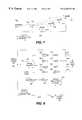
- FIG. 7is a block diagram of a cable television system including a clock source in accordance with the present invention.
- FIG. 8is an electrical block diagram of an optical transmitter for receiving a clock signal from the clock source of FIG. 7 in accordance with the present invention.
- FIG. 9is an illustration of a frame structure for frames of information that can be transmitted by the optical transmitter of FIG. 8 in accordance with the present invention.
- FIG. 1shows a communications system, such as a cable television system 100 having both forward and reverse paths, i.e., having the ability to communicate downstream in the forward direction and upstream in the reverse direction.
- the cable television system 100includes a headend 105 for receiving satellite signals that are demodulated to baseband or an intermediate frequency (IF).
- IFintermediate frequency
- the baseband signalis then converted to cable television signals that are routed throughout the system 100 to subscriber equipment 130 , such as set top decoders, televisions, or computers, located in the residences or offices of system subscribers.
- subscriber equipment 130such as set top decoders, televisions, or computers, located in the residences or offices of system subscribers.
- the headend 105can, for instance, convert the baseband signal to an optical signal that is transmitted over fiber optic cable 110 , in which case a remotely located optical node 115 converts the optical signal to an electrical radio frequency (RF) signal for further transmission through the system 100 over coaxial cable 120 .
- RFradio frequency
- Taps 125 located along the cable 120 at various points in the distribution systemsplit off portions of the RF signal for routing to subscriber equipment 130 coupled to subscriber drops provided at the taps 125 .
- the system 100also has reverse transmission capability so that signals, such as data, video, or voice signals, generated by the subscriber equipment 130 can be provided back to the headend 105 for processing.
- the reverse signalstravel through the taps 125 and any nodes 115 and other cable television equipment, e.g., reverse amplifiers, to the headend 105 .
- RF signals generated by the subscriber equipment 130travel to the node 115 , which converts the RF signals to optical signals for transmission over the fiber optic cable 110 to the headend 105 .
- a digital reverse transmitter 200is provided for transmitting digital optical signals to the headend 105 in the reverse direction.
- the transmitter 200can, for instance, be included within the optical node 115 , although other locations within the cable television system 100 may also include the digital reverse transmitter 200 of the present invention.
- the transmitter 200receives, at an input 202 , an analog information signal that is representative of one or more reverse RF signals from the subscriber equipment 130 .
- the transmitter 200provides a digital optical signal that is generated in accordance with the analog information signal as well as an optional pilot tone that serves to provide a reference level during processing at the headend 105 .
- the digital reverse transmitter 200includes an analog-to-digital (A/D) converter 205 for converting the analog input to a digital signal, i.e., a digital word comprising a particular number of bits, in a conventional manner.
- A/D converter 205for converting the analog input to a digital signal, i.e., a digital word comprising a particular number of bits, in a conventional manner.
- the resolution of the A/D converter 205is dependent upon transmitter design parameters.
- the transmitter 200can also include a digital pilot tone generator 210 for providing a digital pilot tone in the form of a number of bits representative of a particular level and frequency.
- the digital pilot tone generator 210could, for instance, include input switches by which the level and frequency could be varied.
- U.S. Pat. No. 5,563,815 to Jonesshows a digital tone oscillator that could be used to implement the generator 210 included in the transmitter 200 of the present invention.
- a summer 215receives the digital information signal from the A/D converter 205 and the digital pilot tone signal from the generator 210 and digitally adds the two signals by performing binary addition in a known manner.
- the summed signalis then coupled to a parallel-to-serial (P/S) converter, or a serializer 220 , which receives the parallel inputs representative of the summed signal and converts the inputs into a serial bit stream.
- a laser diode 225is then driven to generate an optical signal in accordance with the serial bit stream.
- the serializer 220can also include a driver for driving the laser diode 225 and frame encoding circuitry for encoding the serialized digital signal into frames of data.
- FIG. 3is a block diagram of an optical receiver 305 for receiving the digital optical signal transmitted by the optical transmitter 200 .
- the receiver 305can be, for instance, located in the headend 105 , although other locations, such as any intervening nodes, may also employ the receiver 305 .
- the receiver 305includes a detector, such as a photodiode 310 , for receiving the digital optical signal transmitted over the fiber optic cable 110 and generating therefrom a serial stream of electrical pulses in accordance with the optical signal.
- the output signals provided by the photodiode 310are coupled to a serial-to-parallel (P/S) converter 315 for generating therefrom a set of parallel outputs corresponding to a digital word.
- P/Sserial-to-parallel
- the receiver 305further includes a digital-to-analog (D/A) converter 320 for converting the signal provided at its digital input to an analog signal in a known manner. Thereafter, the analog signal is processed by a filter 325 to separate the pilot tone signal from the information signal. More specifically, the filter 325 preferably comprises a low pass filter that only passes the fundamental frequency component of the output of the D/A converter 320 . As a result, the digital optical receiver 305 is able to provide at its output a reference signal, i.e., the pilot tone, and an analog signal that approximates the analog information signal initially provided to the optical transmitter 200 . Furthermore, this can be done without encountering many of the problems that arise in prior art designs.
- D/Adigital-to-analog
- optical links in the reverse pathuse amplitude modulation to directly modulate a laser generating a reverse optical signal.
- RF output level of the optical receiveris directly dependent upon the optical modulation index (OMI), which in turn is directly related to the RF drive current, the laser threshold current, and the laser bias current of the laser located in the transmitter. Since the laser bias and threshold currents vary with temperature, which in turn causes temperature variations of the OMI, the RF output level of the optical receiver also varies with temperature.
- OMIoptical modulation index
- the laser within the transmitter 200 of the present inventionis digitally modulated so that the RF level information is encoded according to a bit stream; as a result, variations in the OMI, the laser bias current, the laser threshold current, and the temperature do not affect RF output levels of the optical receiver 305 .
- Prior art optical transmission that uses AM modulationalso result in a system in which the linearity of the received optical signal is directly dependent upon the linearity of the transmitting laser and the receiving photodiode. Therefore, non-linearities of those devices can greatly degrade the performance of the reverse path system. Additionally, the non-linear conversion processes of lasers and photodiodes in conventional systems vary with temperature, thus further degrading the performance. Conversely, the digital optical system, i.e., the digital optical transmitter 200 and the digital optical receiver 305 , of the present invention only generates and resolves two amplitude levels rather than a continuum of levels. As a result, linearity requirements of the laser and photodiode are reduced, which results in better performance and less expense.
- Still another advantage of the digital optical transmitter 200 and receiver 305 of the present inventionis that the cable system 100 can, without significant cost or performance penalties, employ an architecture in which fiber stretches deeper into the system 100 .
- the signaldecreases in power as a result of laser noise, Rayleigh backscattering, photodiode shot noise, receiver amplifier noise, unmodulated Fabry-Perot sporadic noise, and post amplifier intrinsic noise.
- CNRcarrier-to-noise ratio
- this problemis mitigated by driving the transmitter laser with more power and/or increasing the receive sensitivity of the receiver photodiode at great expense.
- the system 400includes a headend 105 for generating cable television signals that are split off to subscriber equipment 130 by taps 125 .
- the optical node 415splits off the downstream cable signal for transmission to multiple distribution systems 430 , 435 , or branches. Each branch typically provides service to subscribers located in different geographic regions.
- Upstream reverse signals provided by subscriber equipment 130 in the different branches 430 , 435is transmitted in the form of analog RF signals to the optical node 415 , which combines the signals for further upstream transmission in the form of an optical signal.
- the upstream signals from the different branches 430 , 435can be converted to a digital optical signal in a manner that minimizes or eliminates many of the problems associated with prior art cable television systems.
- FIG. 5is an electrical block diagram of an optical transmitter 500 that can, in accordance with the present invention, be used to process multiple analog inputs.
- the transmitter 500receives a first analog input, such as from a first branch 430 of a cable television system 400 , and, at input 503 , the transmitter 500 receives a second analog input, such as from a second branch 435 of the system 400 .
- First and second A/D converters 205 , 505respectively convert the received RF signals to digital information signals that are separately summed, by summers 215 , 515 , with the digital pilot tone.
- serializers 220 , 520Each summed signal is then serialized by serializers 220 , 520 to result in first and second serial bit streams that are representative of the first and second RF signals, respectively, as separately combined with the digital pilot tone.
- bits of the serial bit streamsare interleaved by an interleaver 550 to form a single digital signal that modulates the laser diode 225 .
- a single digital optical signalcan be provided at the output 504 of the transmitter 500 .
- the receiver 605for processing the digital optical signal generated by the transmitter 500 is shown.
- the receiver 605includes a photodiode 310 for generating electrical pulses from the optical signal and a deinterleaver 650 for deinterleaving the signal comprising the electrical pulses.
- the deinterleaver 650Once the deinterleaver 650 has separated the received signal into separate serial bit streams, the outputs are coupled to first and second S/P converters 315 , 615 , first and second D/A converters 320 , 620 , and first and second filters 325 , 625 to recover approximations of the pilot tone and the RF signals that were provided to the transmitter 500 .
- the interleaver 550 and the deinterleaver 650can be implemented using conventional components.
- the interleaver 550could be a framing device capable of implementing a time-domain-multiplexing (TDM) scheme with respect to the incoming bit streams.
- a frame clock(not shown) would be coupled to the interleaver 550 , and one frame would consist of a number of sub-frames equivalent to the number of incoming bit streams.
- a flag bitwould likely be inserted into the frame for identifying the start of the frame.
- the deinterleaver 650is capable of extracting the frame clock signal from the incoming information and recognizing the flag bits indicative of frame starts. Each bit would then be routed to its respective bit stream to recover the original signals.
- the optical transmission systemwould individually convert each reverse signal to a digital signal, add it to the pilot tone, and serialize the combined signal. All serialized signals would then be combined by the interleaver 550 to generate a bit stream for modulating the laser diode 225 (FIG. 5 ).
- the deinterleaver 650would deinterleave the received digital optical signal to provide five serial signals that would be individually processed by S/P converters, D/A converters, and filters to provide five analog outputs as well as an approximation of the pilot tone.
- reverse signals of the same frequencycan be conveniently sent to the headend 105 over the same return fiber 110 .
- Thisis very important since cable television systems typically only allocate a small amount of bandwidth, e.g., 5-40 MHZ, for return path transmissions, which means that varying the frequency of each return path signal would not be practical.
- a block diagramillustrates a cable television system 700 in which digital optical transmission and reception is clocked by a clock signal provided by a source 710 that preferably generates a sinusoidal signal of a particular frequency.
- the clock source 710can be external, i.e., from outside the system 700 , or internal to the cable television system 700 .
- the clock source 710could be located in the headend 105 and coupled to nodes 715 for transmitting digital reverse optical signals and to any optical hub 705 for combining transmissions from the nodes 715 over a single fiber 110 .
- a cable television systemsuch as the system 700
- a cable television systemsuch as the system 700
- internal clock sources for each nodecould result in slight variations in the clock signals. If the clock signals were not synchronized precisely at the nodes 715 , combining of the received signals at the hub 705 could cause erroneous reception of data at the headend 105 .
- the use of the same clock signal for the hub 705 and nodes 715ensures that data streams received by the hub 705 and retransmitted to the headend 105 are synchronized in time for accurate data transmission and reception.
- FIG. 8illustrates an embodiment of a digital optical transmitter 800 in which an external clock signal is provided.
- the digital optical transmitter 800could reside in an optical node 715 , as shown, or in the optical hub 705 , as will be explained in greater detail below.
- the transmitter 800is shown in FIG. 8 as receiving only four reverse electrical signals via input ports 720 , the transmitter 800 can receive any number of reverse signals.
- Each input port 720is coupled to a reverse path that includes an A/D converter 725 for converting the analog electrical signal to a digital electrical signal and a serializer 730 for converting the digital signal to a serial bit stream.
- Each serial bit stream within the transmitter 800is provided to an interleaver 745 for interleaving the bits of data to generate a single bit stream that modulates the laser diode 750 , which provides a single digital optical signal at output port 755 .
- the bit stream generated by the interleaver 745is clocked by an external clock signal, rather than by an internally generated clock signal.
- the external clock signalis received at clock port 760 and provided to a clock recovery circuit 732 which can comprise, for example, a bandpass filter.
- the output of the clock recovery circuit 732is coupled to an A/D converter 735 for digitizing the clock signal and then to a controller 740 , which controls the interleaver 745 . More specifically, the controller 740 clocks the interleaver 745 at the clock speed or some multiple thereof and controls the interleaver 745 for transmission of frames of data.
- the speed of the interleaved signalis preferably n times the speed of each reverse signal, where n is equal to the number of reverse signals received and interleaved by the digital optical transmitter 800 .
- FIG. 9is an illustration of a frame 900 of data that can be transmitted by the digital optical transmitter 800 .
- the frame 900comprises an opening flag that indicates the start of the frame by including internal communication data, such as a high-level data link control (HDLC) word.
- the opening flagis followed by an address indicative of the transmitting device, e.g., a node 715 , from which a particular reverse signal originates.
- the frame 900further comprises a control word, or framing information, that indicates other frame characteristics, such as the length, in bits or words, of the information that follows the control word.
- Frame check informationsuch as a cyclical redundancy code (CRC) or other error detection/correction information, may also be included in the frame 900 , and the frame 900 concludes with transmission of a closing flag, which is known to both transmitter 800 and receiver.
- CRCcyclical redundancy code
- the frame 900may be different depending upon the signal protocol that is used to transmit the reverse optical signal.
- the least significant bit (LSB) of a periodically occurring word of digital informationis used to insert a signaling bit into the data stream. More specifically, the LSB of every eighth (8 th ) word is used to insert either a bit of the HDLC word or a bit of the framing information, in an alternating pattern.
- this proceduremay vary or be eliminated altogether for other signal protocols.
- FIG. 8is an illustration of a digital optical transmitter 800 included in an optical node 715 .
- a transmitter 800 included in the hub 705is similar, but the A/D converters 725 and serializers 730 would be replaced with optical detectors, such as detector 310 (FIG. 6 ), for generating a digital electrical signals that could be provided directly to the interleaver 745 .
- the transmitting devicee.g., the hub 705
- the receiving devicee.g., the headend 105
- the transmitting devicecould mix a digital pilot tone with the information signal, as described in FIG. 2 .
- synchronization informationcould be transmitted by the transmitting device and a bit synchronizer employed by the receiving device so that the same clock signal does not need to be used and so that a pilot tone does not have to be transmitted.
- use of a synchronizing clock signalis desirable for situations in which a device (e.g., the hub 705 ) receives multiple signals that must be interleaved for retransmission as a single signal.
- the reverse digital transmission system described aboveprovides one or more reverse signals without many of the problems present in prior art systems.
- informationcan be sent from subscribers to the headend in a more reliable and less expensive manner.
Landscapes
- Physics & Mathematics (AREA)
- Electromagnetism (AREA)
- Engineering & Computer Science (AREA)
- Computer Networks & Wireless Communication (AREA)
- Signal Processing (AREA)
- Optics & Photonics (AREA)
- Optical Communication System (AREA)
Abstract
Description
This invention relates generally to fiber optic communications, and more specifically to optical transmitters for use in fiber optic communications.
Cable television systems typically include a headend section for receiving satellite signals and demodulating the signals to baseband. The baseband signal is then converted to an optical signal for transmission from the headend section over fiber optic cable. Optical transmitters are distributed throughout the cable system for splitting and transmitting optical signals, and optical receivers are provided for receiving the optical signals and converting them to radio frequency (RF) signals that are further transmitted along branches of the system over coaxial cable rather than fiber optic cable. Taps are situated along the coaxial cable to tap off the cable signals to subscribers of the system.
Various factors influence the ability to accurately transmit and receive optical signals within a cable television system. As the length of fiber optic cable within a system increases, for example, signal losses also increase. Furthermore, temperature fluctuations, which cause variation in the optical modulation index of the optical transmitter, can result in variation of the radio frequency (RF) output level of the optical receiver. Signal distortions can be caused by non-linearities in the laser and photodiode of the optical transmitter.
Although these problems can be mitigated by employing expensive techniques, e.g., decreasing fiber lengths between optical nodes, such techniques may prohibitively increase costs to both subscribers and service providers. Thus, what is needed is a better way to provide reliable and accurate transmission of optical signals within a cable television system.
FIG. 1 is a block diagram of a cable television system in accordance with the present invention.
FIG. 2 is an electrical block diagram of an optical transmitter included in the cable television system of FIG. 1 in accordance with the present invention.
FIG. 3 is an electrical block diagram of an optical receiver included in the cable television system of FIG. 1 in accordance with the present invention.
FIG. 4 is a block diagram of a cable television having multiple outputs to subscriber regions in accordance with the present invention.
FIG. 5 is an electrical block diagram of an optical transmitter included in the cable television system of FIG. 4 in accordance with the present invention.
FIG. 6 is an electrical block diagram of an optical receiver included in the cable television system of FIG. 4 in accordance with the present invention.
FIG. 7 is a block diagram of a cable television system including a clock source in accordance with the present invention.
FIG. 8 is an electrical block diagram of an optical transmitter for receiving a clock signal from the clock source of FIG. 7 in accordance with the present invention.
FIG. 9 is an illustration of a frame structure for frames of information that can be transmitted by the optical transmitter of FIG. 8 in accordance with the present invention.
FIG. 1 shows a communications system, such as acable television system 100 having both forward and reverse paths, i.e., having the ability to communicate downstream in the forward direction and upstream in the reverse direction. Thecable television system 100 includes a headend105 for receiving satellite signals that are demodulated to baseband or an intermediate frequency (IF). The baseband signal is then converted to cable television signals that are routed throughout thesystem 100 tosubscriber equipment 130, such as set top decoders, televisions, or computers, located in the residences or offices of system subscribers. Theheadend 105 can, for instance, convert the baseband signal to an optical signal that is transmitted over fiberoptic cable 110, in which case a remotely locatedoptical node 115 converts the optical signal to an electrical radio frequency (RF) signal for further transmission through thesystem 100 overcoaxial cable 120.Taps 125 located along thecable 120 at various points in the distribution system split off portions of the RF signal for routing tosubscriber equipment 130 coupled to subscriber drops provided at thetaps 125.
Thesystem 100, as mentioned, also has reverse transmission capability so that signals, such as data, video, or voice signals, generated by thesubscriber equipment 130 can be provided back to theheadend 105 for processing. The reverse signals travel through thetaps 125 and anynodes 115 and other cable television equipment, e.g., reverse amplifiers, to theheadend 105. In the configuration shown in FIG. 1, RF signals generated by thesubscriber equipment 130 travel to thenode 115, which converts the RF signals to optical signals for transmission over the fiberoptic cable 110 to theheadend 105.
Referring to FIG. 2, a digitalreverse transmitter 200 is provided for transmitting digital optical signals to theheadend 105 in the reverse direction. Thetransmitter 200 can, for instance, be included within theoptical node 115, although other locations within thecable television system 100 may also include the digitalreverse transmitter 200 of the present invention. Thetransmitter 200 receives, at aninput 202, an analog information signal that is representative of one or more reverse RF signals from thesubscriber equipment 130. At itsoutput 204, thetransmitter 200 provides a digital optical signal that is generated in accordance with the analog information signal as well as an optional pilot tone that serves to provide a reference level during processing at theheadend 105.
More specifically, thedigital reverse transmitter 200 includes an analog-to-digital (A/D)converter 205 for converting the analog input to a digital signal, i.e., a digital word comprising a particular number of bits, in a conventional manner. The resolution of the A/D converter 205, of course, is dependent upon transmitter design parameters. Thetransmitter 200 can also include a digitalpilot tone generator 210 for providing a digital pilot tone in the form of a number of bits representative of a particular level and frequency. The digitalpilot tone generator 210 could, for instance, include input switches by which the level and frequency could be varied. U.S. Pat. No. 5,563,815 to Jones, the teachings of which are hereby incorporated by reference, shows a digital tone oscillator that could be used to implement thegenerator 210 included in thetransmitter 200 of the present invention.
Asummer 215 receives the digital information signal from the A/D converter 205 and the digital pilot tone signal from thegenerator 210 and digitally adds the two signals by performing binary addition in a known manner. The summed signal is then coupled to a parallel-to-serial (P/S) converter, or aserializer 220, which receives the parallel inputs representative of the summed signal and converts the inputs into a serial bit stream. Alaser diode 225 is then driven to generate an optical signal in accordance with the serial bit stream. It will be appreciated that theserializer 220 can also include a driver for driving thelaser diode 225 and frame encoding circuitry for encoding the serialized digital signal into frames of data.
FIG. 3 is a block diagram of anoptical receiver 305 for receiving the digital optical signal transmitted by theoptical transmitter 200. Thereceiver 305 can be, for instance, located in theheadend 105, although other locations, such as any intervening nodes, may also employ thereceiver 305. Thereceiver 305 includes a detector, such as aphotodiode 310, for receiving the digital optical signal transmitted over the fiberoptic cable 110 and generating therefrom a serial stream of electrical pulses in accordance with the optical signal. The output signals provided by thephotodiode 310 are coupled to a serial-to-parallel (P/S)converter 315 for generating therefrom a set of parallel outputs corresponding to a digital word. Thereceiver 305 further includes a digital-to-analog (D/A)converter 320 for converting the signal provided at its digital input to an analog signal in a known manner. Thereafter, the analog signal is processed by afilter 325 to separate the pilot tone signal from the information signal. More specifically, thefilter 325 preferably comprises a low pass filter that only passes the fundamental frequency component of the output of the D/A converter 320. As a result, the digitaloptical receiver 305 is able to provide at its output a reference signal, i.e., the pilot tone, and an analog signal that approximates the analog information signal initially provided to theoptical transmitter 200. Furthermore, this can be done without encountering many of the problems that arise in prior art designs.
In conventional cable television systems, optical links in the reverse path use amplitude modulation to directly modulate a laser generating a reverse optical signal. As a result, RF output level of the optical receiver is directly dependent upon the optical modulation index (OMI), which in turn is directly related to the RF drive current, the laser threshold current, and the laser bias current of the laser located in the transmitter. Since the laser bias and threshold currents vary with temperature, which in turn causes temperature variations of the OMI, the RF output level of the optical receiver also varies with temperature. However, the laser within thetransmitter 200 of the present invention is digitally modulated so that the RF level information is encoded according to a bit stream; as a result, variations in the OMI, the laser bias current, the laser threshold current, and the temperature do not affect RF output levels of theoptical receiver 305.
Prior art optical transmission that uses AM modulation also result in a system in which the linearity of the received optical signal is directly dependent upon the linearity of the transmitting laser and the receiving photodiode. Therefore, non-linearities of those devices can greatly degrade the performance of the reverse path system. Additionally, the non-linear conversion processes of lasers and photodiodes in conventional systems vary with temperature, thus further degrading the performance. Conversely, the digital optical system, i.e., the digitaloptical transmitter 200 and the digitaloptical receiver 305, of the present invention only generates and resolves two amplitude levels rather than a continuum of levels. As a result, linearity requirements of the laser and photodiode are reduced, which results in better performance and less expense.
Another problem associated with conventional cable television systems is that reverse pilot tones are seldom used due to the complications and costs. When such pilot tones are used, an additional oscillator, which is not digital, is generally located outside the transmitter and is susceptible to temperature variations. The oscillator signal is combined with the analog RF signal, and the combined signal is used to modulate the laser diode current to provide an optical output. Prior art pilot tones are used by an optical transmitter to ensure that there is always a minimum RF signal modulating the laser, thereby decreasing the spurious noise generated by the laser, and by an optical receiver for gain control purposes. However, since oscillator output level drifts with temperature, the RF output level of the optical receiver will also drift with temperature so that gain control is essentially useless. As mentioned above, use of the combined digital pilot tone and digital information signal according to the present invention solves the prior art temperature dependency problems. At the same time, the digital pilot tone can be used by thetransmitter 200 to modulate the laser even when no RF input is present.
Still another advantage of the digitaloptical transmitter 200 andreceiver 305 of the present invention is that thecable system 100 can, without significant cost or performance penalties, employ an architecture in which fiber stretches deeper into thesystem 100. As a cable television signal travels along afiber optic cable 110, the signal decreases in power as a result of laser noise, Rayleigh backscattering, photodiode shot noise, receiver amplifier noise, unmodulated Fabry-Perot sporadic noise, and post amplifier intrinsic noise. These factors cause the carrier-to-noise ratio (CNR) to decrease. Conventionally, this problem is mitigated by driving the transmitter laser with more power and/or increasing the receive sensitivity of the receiver photodiode at great expense. However, this need not be done in asystem 100 according to the present invention since the noise sources and corresponding signal degradation resulting from increased fiber lengths does not affect recovery of information to the same extent as in prior art systems.
Referring next to FIG. 4, a modifiedcable television system 400 is depicted. Thesystem 400 includes aheadend 105 for generating cable television signals that are split off tosubscriber equipment 130 bytaps 125. However, in thesystem 400, theoptical node 415 splits off the downstream cable signal for transmission tomultiple distribution systems subscriber equipment 130 in thedifferent branches optical node 415, which combines the signals for further upstream transmission in the form of an optical signal. According to the present invention, the upstream signals from thedifferent branches
FIG. 5 is an electrical block diagram of anoptical transmitter 500 that can, in accordance with the present invention, be used to process multiple analog inputs. Atinput 502, thetransmitter 500 receives a first analog input, such as from afirst branch 430 of acable television system 400, and, atinput 503, thetransmitter 500 receives a second analog input, such as from asecond branch 435 of thesystem 400. First and second A/D converters summers serializers interleaver 550 to form a single digital signal that modulates thelaser diode 225. As a result, a single digital optical signal can be provided at theoutput 504 of thetransmitter 500.
Referring to FIG. 6, anoptical receiver 605 for processing the digital optical signal generated by thetransmitter 500 is shown. Thereceiver 605 includes aphotodiode 310 for generating electrical pulses from the optical signal and adeinterleaver 650 for deinterleaving the signal comprising the electrical pulses. Once thedeinterleaver 650 has separated the received signal into separate serial bit streams, the outputs are coupled to first and second S/P converters A converters second filters transmitter 500.
It will be appreciated that theinterleaver 550 and thedeinterleaver 650 can be implemented using conventional components. Typically, theinterleaver 550 could be a framing device capable of implementing a time-domain-multiplexing (TDM) scheme with respect to the incoming bit streams. In such an implementation, a frame clock (not shown) would be coupled to theinterleaver 550, and one frame would consist of a number of sub-frames equivalent to the number of incoming bit streams. A flag bit would likely be inserted into the frame for identifying the start of the frame. Thedeinterleaver 650 is capable of extracting the frame clock signal from the incoming information and recognizing the flag bits indicative of frame starts. Each bit would then be routed to its respective bit stream to recover the original signals.
Although only two input branches into thetransmitter 500 and two processing paths through thetransmitter 500 and thereceiver 605 are shown, a plurality of paths can be provided depending upon the number of incoming analog signals to be processed by thetransmitter 500. For example, if five RF signals are traveling in the reverse paths of five branches of a cable television system, the optical transmission system according to the present invention would individually convert each reverse signal to a digital signal, add it to the pilot tone, and serialize the combined signal. All serialized signals would then be combined by theinterleaver 550 to generate a bit stream for modulating the laser diode225 (FIG.5). On the receiver end, thedeinterleaver 650 would deinterleave the received digital optical signal to provide five serial signals that would be individually processed by S/P converters, D/A converters, and filters to provide five analog outputs as well as an approximation of the pilot tone.
In this manner, reverse signals of the same frequency can be conveniently sent to theheadend 105 over thesame return fiber 110. This is very important since cable television systems typically only allocate a small amount of bandwidth, e.g., 5-40 MHZ, for return path transmissions, which means that varying the frequency of each return path signal would not be practical.
Referring next to FIG. 7, a block diagram illustrates acable television system 700 in which digital optical transmission and reception is clocked by a clock signal provided by asource 710 that preferably generates a sinusoidal signal of a particular frequency. Theclock source 710 can be external, i.e., from outside thesystem 700, or internal to thecable television system 700. For example, theclock source 710 could be located in theheadend 105 and coupled tonodes 715 for transmitting digital reverse optical signals and to anyoptical hub 705 for combining transmissions from thenodes 715 over asingle fiber 110.
When a cable television system, such as thesystem 700, is large enough to include ahub 705 and multiple branches, each including its ownoptical node 715, internal clock sources for each node could result in slight variations in the clock signals. If the clock signals were not synchronized precisely at thenodes 715, combining of the received signals at thehub 705 could cause erroneous reception of data at theheadend 105. The use of the same clock signal for thehub 705 andnodes 715, on the other hand, ensures that data streams received by thehub 705 and retransmitted to theheadend 105 are synchronized in time for accurate data transmission and reception.
FIG. 8 illustrates an embodiment of a digitaloptical transmitter 800 in which an external clock signal is provided. The digitaloptical transmitter 800 could reside in anoptical node 715, as shown, or in theoptical hub 705, as will be explained in greater detail below. Although thetransmitter 800 is shown in FIG. 8 as receiving only four reverse electrical signals viainput ports 720, thetransmitter 800 can receive any number of reverse signals. Eachinput port 720 is coupled to a reverse path that includes an A/D converter 725 for converting the analog electrical signal to a digital electrical signal and aserializer 730 for converting the digital signal to a serial bit stream. Each serial bit stream within thetransmitter 800 is provided to aninterleaver 745 for interleaving the bits of data to generate a single bit stream that modulates thelaser diode 750, which provides a single digital optical signal atoutput port 755.
According to this embodiment of the present invention, the bit stream generated by theinterleaver 745 is clocked by an external clock signal, rather than by an internally generated clock signal. The external clock signal is received atclock port 760 and provided to aclock recovery circuit 732 which can comprise, for example, a bandpass filter. The output of theclock recovery circuit 732 is coupled to an A/D converter 735 for digitizing the clock signal and then to acontroller 740, which controls theinterleaver 745. More specifically, thecontroller 740 clocks theinterleaver 745 at the clock speed or some multiple thereof and controls theinterleaver 745 for transmission of frames of data. So that transmission speed is not compromised by the time-division-multiplexing of multiple reverse signals, the speed of the interleaved signal is preferably n times the speed of each reverse signal, where n is equal to the number of reverse signals received and interleaved by the digitaloptical transmitter 800.
FIG. 9 is an illustration of aframe 900 of data that can be transmitted by the digitaloptical transmitter 800. Preferably, theframe 900 comprises an opening flag that indicates the start of the frame by including internal communication data, such as a high-level data link control (HDLC) word. The opening flag is followed by an address indicative of the transmitting device, e.g., anode 715, from which a particular reverse signal originates. Theframe 900 further comprises a control word, or framing information, that indicates other frame characteristics, such as the length, in bits or words, of the information that follows the control word. Frame check information, such as a cyclical redundancy code (CRC) or other error detection/correction information, may also be included in theframe 900, and theframe 900 concludes with transmission of a closing flag, which is known to bothtransmitter 800 and receiver.
It will be appreciated that theframe 900 may be different depending upon the signal protocol that is used to transmit the reverse optical signal. When the HDLC protocol is used, for example, the least significant bit (LSB) of a periodically occurring word of digital information is used to insert a signaling bit into the data stream. More specifically, the LSB of every eighth (8th) word is used to insert either a bit of the HDLC word or a bit of the framing information, in an alternating pattern. However, this procedure may vary or be eliminated altogether for other signal protocols.
As mentioned above, FIG. 8 is an illustration of a digitaloptical transmitter 800 included in anoptical node 715. One of ordinary skill in the art will understand that atransmitter 800 included in thehub 705 is similar, but the A/D converters 725 andserializers 730 would be replaced with optical detectors, such as detector310 (FIG.6), for generating a digital electrical signals that could be provided directly to theinterleaver 745.
It will further be understood that, when a single optical signal is received, such as by theheadend 105, the transmitting device (e.g., the hub705) and the receiving device (e.g., the headend105) need not necessarily receive the same external clock signal. Instead, since there is no interleaving of received signal with which to contend, the transmitting device could mix a digital pilot tone with the information signal, as described in FIG.2. Alternatively, synchronization information could be transmitted by the transmitting device and a bit synchronizer employed by the receiving device so that the same clock signal does not need to be used and so that a pilot tone does not have to be transmitted. However, as mentioned above, use of a synchronizing clock signal is desirable for situations in which a device (e.g., the hub705) receives multiple signals that must be interleaved for retransmission as a single signal.
In summary, the reverse digital transmission system described above provides one or more reverse signals without many of the problems present in prior art systems. As a result, information can be sent from subscribers to the headend in a more reliable and less expensive manner.
Claims (8)
1. A communication system for providing information, the communication system comprising:
a clock source for generating a clock signal having a clock speed;
an optical receiver coupled to the clock source for recovering the information in accordance with the clock signal;
an optical transmitter coupled to the clock source and the optical receiver, the optical transmitter comprising:
first and second input ports for receiving first and second information signals:
a clock port coupled to the clock source for receiving the clock signal;
a clock recovery circuit for filtering the clock signal provided at the clock port;
an analog-to-digital (A/D) converter coupled to the clock recovery circuit for digitizing the clock signal;
an interleaver coupled to the first and second input ports and to the clock port, wherein the interleaver interleaves bits of the first and second information signals in accordance with the clock signal, after it has been digitized, to generate a serial bit stream;
a controller coupled to the A/D converter and the interleaver for clocking the interleaver at a multiple of the clock speed; and
a laser diode coupled to the interleaver and modulated by the serial bit stream to generate a digital optical signal; and
an optical communication channel coupled between the laser diode of the optical transmitter and the optical receiver.
2. The communication system ofclaim 1 , wherein the first information signal and the second information signal are provided to the optical transmitter at a first speed, and wherein the digital optical signal provided by the laser diode is transmitted at a second speed that is a multiple of the first speed.
3. The communication system ofclaim 1 , wherein the communication system comprises a cable television system.
4. The communication system ofclaim 1 , wherein:
the communication system comprises a cable television system including a headend for transmitting forward optical signals in a forward direction, an optical hub for forwarding the forward optical signals over branches of the cable television system, and optical nodes located in branches of the cable television system for converting the forward optical signals to forward electrical signals.
5. The communication system ofclaim 1 , wherein the controller controls the interleaver to generate frames of data according to a signal protocol.
6. The communication system ofclaim 1 , wherein the clock source is included in the headend, from which the clock signal is provided to the optical hub and to the optical nodes.
7. A cable television system for transmitting forward and reverse signals, the cable television system comprising:
a headend for generating forward optical signals and for receiving reverse optical signals, the headend including a clock source for generating a clock signal, having a clock speed;
an optical hub coupled to the headend for receiving the clock signal and for forwarding the forward optical signals throughout the cable television system, the optical hub including a reverse optical transmitter comprising:
first and second input ports for receiving first and second information signals;
first and second analog-to-digital (A/D) converters for respectively receiving the first and second information signals and generating therefrom first and second digital information signals;
first and second serializers coupled respectively to the first and second A/D converters for converting the first and second digital information signals into first and second serial bit streams;
a clock port for receiving the clock signal;
a clock recovery circuit for filtering the clock signal provided at the clock port;
a clock A/D converter coupled to the clock recovery circuit for digitizing the clock signal;
an interleaver coupled to the first and second serializers and to the clock A/D converter,
a controller coupled to the clock A/D converter and the interleaver for clocking the interleaver at a multiple of the clock speed,
wherein the interleaver interleaves bits of the first and second serial bit streams in accordance with the clock signal to generate a serial bit stream; and
a laser diode coupled to the interleaver and modulated by the serial bit stream to generate a digital optical signal for transmission to the headend; and
an optical communication channel coupled between the optical hub and the headend.
8. The cable television system ofclaim 7 , wherein the controller controls the interleaver to generate frames of data according to a signal protocol.
Priority Applications (4)
| Application Number | Priority Date | Filing Date | Title |
|---|---|---|---|
| US09/169,612US6356374B1 (en) | 1998-10-09 | 1998-10-09 | Digital optical transmitter |
| EP99968845AEP1119929A2 (en) | 1998-10-09 | 1999-10-08 | Digital optical transceiver |
| BR9914212-0ABR9914212A (en) | 1998-10-09 | 1999-10-08 | Digital optical transmitter |
| PCT/US1999/023556WO2000025459A2 (en) | 1998-10-09 | 1999-10-08 | Digital optical transceiver |
Applications Claiming Priority (1)
| Application Number | Priority Date | Filing Date | Title |
|---|---|---|---|
| US09/169,612US6356374B1 (en) | 1998-10-09 | 1998-10-09 | Digital optical transmitter |
Publications (1)
| Publication Number | Publication Date |
|---|---|
| US6356374B1true US6356374B1 (en) | 2002-03-12 |
Family
ID=22616418
Family Applications (1)
| Application Number | Title | Priority Date | Filing Date |
|---|---|---|---|
| US09/169,612Expired - LifetimeUS6356374B1 (en) | 1998-10-09 | 1998-10-09 | Digital optical transmitter |
Country Status (4)
| Country | Link |
|---|---|
| US (1) | US6356374B1 (en) |
| EP (1) | EP1119929A2 (en) |
| BR (1) | BR9914212A (en) |
| WO (1) | WO2000025459A2 (en) |
Cited By (55)
| Publication number | Priority date | Publication date | Assignee | Title |
|---|---|---|---|---|
| US20010021051A1 (en)* | 1999-12-29 | 2001-09-13 | Samsung Electronics Co.,Ltd. | Optical transmission system for compensating for transmission loss |
| US20020093966A1 (en)* | 2000-03-06 | 2002-07-18 | Valentino Liva | Enhanced CMTS for reliability, availability, and serviceability |
| US20020129379A1 (en)* | 1999-12-13 | 2002-09-12 | Levinson Frank H. | System and method for transmitting data on return path of a cable television system |
| US20020136203A1 (en)* | 2000-03-06 | 2002-09-26 | Valentino Liva | Enhanced fiber nodes with CMTS capability |
| US20020167693A1 (en)* | 2000-12-21 | 2002-11-14 | Quellan, Inc. | Increasing data throughput in optical fiber transmission systems |
| US20020181053A1 (en)* | 2001-05-30 | 2002-12-05 | Nec Corporation | Optical communication system including replaceable electro-optic and opto-electric converters |
| US6498663B1 (en)* | 1999-09-24 | 2002-12-24 | Scientific-Atlanta, Inc. | Methods and systems for detecting optical link performance of an optical link in a hybrid fiber coaxial path |
| US20020196510A1 (en)* | 2001-04-04 | 2002-12-26 | Hietala Vincent Mark | Method and system for decoding multilevel signals |
| US20030030873A1 (en)* | 2001-05-09 | 2003-02-13 | Quellan, Inc. | High-speed adjustable multilevel light modulation |
| US20030072050A1 (en)* | 2001-03-29 | 2003-04-17 | Quellan, Inc. | Multilevel pulse position modulation for efficient fiber optic communication |
| US20030110509A1 (en)* | 1999-12-13 | 2003-06-12 | Levinson Frank H. | Cable television return link system with high data-rate side-band communication channels |
| US20030113158A1 (en)* | 2001-12-14 | 2003-06-19 | Compaq Information Technologies Group, L.P. | Technique for providing a pivot structure that faciliates the rapid formation of pivot couplings between components |
| US20030154498A1 (en)* | 2002-02-12 | 2003-08-14 | Sage Gerald F. | Efficient transmission of digital return path data in cable television return path |
| US20030154495A1 (en)* | 2002-02-12 | 2003-08-14 | Finisar Corporation | Data rate compression device for cable television return path using bandpass puncturing |
| US20030154494A1 (en)* | 2002-02-08 | 2003-08-14 | Sage Gerald Francis | Bandpass component decimation and transmission of data in cable television digital return path |
| US20030156655A1 (en)* | 2002-02-15 | 2003-08-21 | Quellan, Inc. | Multi-level signal clock recovery technique |
| US20030156602A1 (en)* | 2002-02-19 | 2003-08-21 | Sage Gerald F. | Asynchronous digital signal combiner and method of combining asynchronous digital signals in cable television return path |
| US20040012433A1 (en)* | 2002-07-15 | 2004-01-22 | Quellan, Inc. | Adaptive noise filtering and equalization for optimal high speed multilevel signal decoding |
| US20040103441A1 (en)* | 2002-10-30 | 2004-05-27 | Williams Andrew R. | Return path transmitter with extended digital processing circuitry |
| US20040105462A1 (en)* | 2002-11-12 | 2004-06-03 | Quellan, Inc. | High-speed analog-to-digital conversion with improved robustness to timing uncertainty |
| WO2004008663A3 (en)* | 2002-07-11 | 2004-09-30 | Intel Corp | Laser driver circuit and system |
| US20040233947A1 (en)* | 2003-05-21 | 2004-11-25 | Asuri Bhushan S. | Laser driver circuit and system |
| US20040264974A1 (en)* | 2003-06-06 | 2004-12-30 | Sorenson Donald C. | Cable television passive optical network |
| US20050030884A1 (en)* | 2003-08-07 | 2005-02-10 | Quellan, Inc. | Method and system for crosstalk cancellation |
| US20050105962A1 (en)* | 2003-07-01 | 2005-05-19 | Isaac Weiser | Connector and method of use thereof |
| US20050105370A1 (en)* | 2001-11-21 | 2005-05-19 | Interdigital Technology Corporation | Apparatus and method for bidirectional transfer of data by a base station |
| US20050180520A1 (en)* | 2003-12-22 | 2005-08-18 | Quellan, Inc. | Method and system for slicing a communication signal |
| US20050226353A1 (en)* | 2003-11-17 | 2005-10-13 | Quellan, Inc. | Method and system for antenna interference cancellation |
| US20050254523A1 (en)* | 2004-05-12 | 2005-11-17 | Oyadomari Randy I | Automated ethernet configuration of CATV network |
| US20050273837A1 (en)* | 2004-05-12 | 2005-12-08 | Oyadomari Randy I | Single master clock control of ethernet data transfer over both a cable TV return path and an ethernet forward path |
| US20050273836A1 (en)* | 2004-05-12 | 2005-12-08 | Oyadomari Randy I | Changing communication mode in a CATV pathway using mute commands |
| US6993016B1 (en)* | 2000-11-16 | 2006-01-31 | Juniper Networks, Inc. | Methods and apparatus for transmission of analog channels over digital packet networks |
| US20060178157A1 (en)* | 2004-12-14 | 2006-08-10 | Quellan, Inc. | Method and system for reducing signal interference |
| US20060188259A1 (en)* | 2005-02-19 | 2006-08-24 | James Furey | HDSL optical fiber transmission system and method |
| US20070060059A1 (en)* | 2004-12-14 | 2007-03-15 | Quellan, Inc. | Method and system for automatic control in an interference cancellation device |
| US20070064923A1 (en)* | 2003-08-07 | 2007-03-22 | Quellan, Inc. | Method and system for signal emulation |
| US20070222654A1 (en)* | 2001-03-29 | 2007-09-27 | Quellan, Inc. | Increasing data throughput in optical fiber transmission systems |
| US20070253495A1 (en)* | 2006-04-26 | 2007-11-01 | Quellan, Inc. | Method and system for reducing radiated emissions from a communications channel |
| US20080268800A1 (en)* | 2001-11-21 | 2008-10-30 | Interdigital Technology Corporation | Hybrid parallel/serial bus interface |
| US7519297B2 (en) | 2002-11-08 | 2009-04-14 | Finisar Corporation | Cable television system with separate radio frequency hub and ethernet hub |
| US20090203333A1 (en)* | 2008-02-13 | 2009-08-13 | Analog Devices, Inc. | High-speed data transmitters |
| US20100061291A1 (en)* | 2000-07-19 | 2010-03-11 | Adc Telecommunications, Inc. | Point-to-multipoint digital radio frequency transport |
| US7725036B2 (en) | 2002-02-12 | 2010-05-25 | Finisar Corporation | Efficient transmission of digital return path data in cable television return path |
| US8958789B2 (en) | 2002-12-03 | 2015-02-17 | Adc Telecommunications, Inc. | Distributed digital antenna system |
| US9037143B2 (en) | 2010-08-16 | 2015-05-19 | Corning Optical Communications LLC | Remote antenna clusters and related systems, components, and methods supporting digital data signal propagation between remote antenna units |
| US9042732B2 (en) | 2010-05-02 | 2015-05-26 | Corning Optical Communications LLC | Providing digital data services in optical fiber-based distributed radio frequency (RF) communication systems, and related components and methods |
| US9325429B2 (en) | 2011-02-21 | 2016-04-26 | Corning Optical Communications LLC | Providing digital data services as electrical signals and radio-frequency (RF) communications over optical fiber in distributed communications systems, and related components and methods |
| US9525488B2 (en) | 2010-05-02 | 2016-12-20 | Corning Optical Communications LLC | Digital data services and/or power distribution in optical fiber-based distributed communications systems providing digital data and radio frequency (RF) communications services, and related components and methods |
| US10096909B2 (en) | 2014-11-03 | 2018-10-09 | Corning Optical Communications Wireless Ltd. | Multi-band monopole planar antennas configured to facilitate improved radio frequency (RF) isolation in multiple-input multiple-output (MIMO) antenna arrangement |
| US10110308B2 (en) | 2014-12-18 | 2018-10-23 | Corning Optical Communications Wireless Ltd | Digital interface modules (DIMs) for flexibly distributing digital and/or analog communications signals in wide-area analog distributed antenna systems (DASs) |
| US10135533B2 (en) | 2014-11-13 | 2018-11-20 | Corning Optical Communications Wireless Ltd | Analog distributed antenna systems (DASS) supporting distribution of digital communications signals interfaced from a digital signal source and analog radio frequency (RF) communications signals |
| US10187151B2 (en) | 2014-12-18 | 2019-01-22 | Corning Optical Communications Wireless Ltd | Digital-analog interface modules (DAIMs) for flexibly distributing digital and/or analog communications signals in wide-area analog distributed antenna systems (DASs) |
| US10499269B2 (en) | 2015-11-12 | 2019-12-03 | Commscope Technologies Llc | Systems and methods for assigning controlled nodes to channel interfaces of a controller |
| US10659163B2 (en) | 2014-09-25 | 2020-05-19 | Corning Optical Communications LLC | Supporting analog remote antenna units (RAUs) in digital distributed antenna systems (DASs) using analog RAU digital adaptors |
| US11178609B2 (en) | 2010-10-13 | 2021-11-16 | Corning Optical Communications LLC | Power management for remote antenna units in distributed antenna systems |
Families Citing this family (3)
| Publication number | Priority date | Publication date | Assignee | Title |
|---|---|---|---|---|
| US6415260B1 (en)* | 1999-04-21 | 2002-07-02 | Taiwan Semiconductor Manufacturing Co., Ltd | Dynamic capacity demand forecast system |
| US6462851B1 (en)* | 2001-04-23 | 2002-10-08 | Scientific-Atlanta, Inc. | Network and method for transmitting reverse analog signals by sub-sampling the digital reverse bandwidth |
| CN1618152A (en)* | 2001-12-12 | 2005-05-18 | 通用仪器公司 | Return Path Transmitter with Laser Control Closed Loop for Use in Hybrid Fiber/Coax Transmission Systems |
Citations (15)
| Publication number | Priority date | Publication date | Assignee | Title |
|---|---|---|---|---|
| US3995120A (en) | 1975-05-30 | 1976-11-30 | Gte Automatic Electric Laboratories Incorporated | Digital time-division multiplexing system |
| WO1988005233A1 (en) | 1987-01-05 | 1988-07-14 | British Telecommunications Public Limited Company | Optical communications network |
| US4759018A (en) | 1985-06-17 | 1988-07-19 | At&T Bell Laboratories | Higher order digital transmission system including a multiplexer and a demultiplexer |
| US5018142A (en) | 1988-03-04 | 1991-05-21 | Digital Equipment Corporation | Technique for organizing and coding serial binary data from a plurality of data lines for transmission over a single transmission line |
| US5420583A (en) | 1991-11-06 | 1995-05-30 | Cray Research, Inc. | Fiber optic channel extender interface method and apparatus |
| US5426527A (en)* | 1991-11-12 | 1995-06-20 | Alliant Techsystems Inc. | System for transmitting multiple signals across a single fiber optic channel |
| US5459607A (en) | 1993-04-19 | 1995-10-17 | C-Cor/Comlux, Inc. | Synchronous optical digital transmission system and method |
| US5544161A (en)* | 1995-03-28 | 1996-08-06 | Bell Atlantic Network Services, Inc. | ATM packet demultiplexer for use in full service network having distributed architecture |
| US5553064A (en)* | 1994-04-05 | 1996-09-03 | Stanford Telecommunications, Inc. | High speed bidirectional digital cable transmission system |
| US5563815A (en) | 1993-08-30 | 1996-10-08 | Fostex Research & Development, Inc. | Digital tone oscillator for certain exact frequencies and method for generating tones |
| US5610911A (en)* | 1993-09-28 | 1997-03-11 | Nec Corporation | Method and device for channel selection |
| US5631757A (en) | 1995-06-07 | 1997-05-20 | Lucent Technologies Inc. | Full-duplex data communication system using different transmit and receive data symbol lengths |
| US5644622A (en) | 1992-09-17 | 1997-07-01 | Adc Telecommunications, Inc. | Cellular communications system with centralized base stations and distributed antenna units |
| WO1997028611A1 (en) | 1996-02-06 | 1997-08-07 | Next Level Communications | Synchronization and downconversion in tdm/tdma systems |
| US5694232A (en)* | 1995-12-06 | 1997-12-02 | Ericsson Raynet | Full duplex optical modem for broadband access network |
- 1998
- 1998-10-09USUS09/169,612patent/US6356374B1/ennot_activeExpired - Lifetime
- 1999
- 1999-10-08BRBR9914212-0Apatent/BR9914212A/ennot_activeApplication Discontinuation
- 1999-10-08EPEP99968845Apatent/EP1119929A2/ennot_activeWithdrawn
- 1999-10-08WOPCT/US1999/023556patent/WO2000025459A2/ennot_activeApplication Discontinuation
Patent Citations (15)
| Publication number | Priority date | Publication date | Assignee | Title |
|---|---|---|---|---|
| US3995120A (en) | 1975-05-30 | 1976-11-30 | Gte Automatic Electric Laboratories Incorporated | Digital time-division multiplexing system |
| US4759018A (en) | 1985-06-17 | 1988-07-19 | At&T Bell Laboratories | Higher order digital transmission system including a multiplexer and a demultiplexer |
| WO1988005233A1 (en) | 1987-01-05 | 1988-07-14 | British Telecommunications Public Limited Company | Optical communications network |
| US5018142A (en) | 1988-03-04 | 1991-05-21 | Digital Equipment Corporation | Technique for organizing and coding serial binary data from a plurality of data lines for transmission over a single transmission line |
| US5420583A (en) | 1991-11-06 | 1995-05-30 | Cray Research, Inc. | Fiber optic channel extender interface method and apparatus |
| US5426527A (en)* | 1991-11-12 | 1995-06-20 | Alliant Techsystems Inc. | System for transmitting multiple signals across a single fiber optic channel |
| US5644622A (en) | 1992-09-17 | 1997-07-01 | Adc Telecommunications, Inc. | Cellular communications system with centralized base stations and distributed antenna units |
| US5459607A (en) | 1993-04-19 | 1995-10-17 | C-Cor/Comlux, Inc. | Synchronous optical digital transmission system and method |
| US5563815A (en) | 1993-08-30 | 1996-10-08 | Fostex Research & Development, Inc. | Digital tone oscillator for certain exact frequencies and method for generating tones |
| US5610911A (en)* | 1993-09-28 | 1997-03-11 | Nec Corporation | Method and device for channel selection |
| US5553064A (en)* | 1994-04-05 | 1996-09-03 | Stanford Telecommunications, Inc. | High speed bidirectional digital cable transmission system |
| US5544161A (en)* | 1995-03-28 | 1996-08-06 | Bell Atlantic Network Services, Inc. | ATM packet demultiplexer for use in full service network having distributed architecture |
| US5631757A (en) | 1995-06-07 | 1997-05-20 | Lucent Technologies Inc. | Full-duplex data communication system using different transmit and receive data symbol lengths |
| US5694232A (en)* | 1995-12-06 | 1997-12-02 | Ericsson Raynet | Full duplex optical modem for broadband access network |
| WO1997028611A1 (en) | 1996-02-06 | 1997-08-07 | Next Level Communications | Synchronization and downconversion in tdm/tdma systems |
Cited By (144)
| Publication number | Priority date | Publication date | Assignee | Title |
|---|---|---|---|---|
| US6498663B1 (en)* | 1999-09-24 | 2002-12-24 | Scientific-Atlanta, Inc. | Methods and systems for detecting optical link performance of an optical link in a hybrid fiber coaxial path |
| US20080019706A1 (en)* | 1999-12-13 | 2008-01-24 | Finisar Corporation | System and method for transmitting data on return path of a cable television system |
| US7778554B2 (en) | 1999-12-13 | 2010-08-17 | Finisar Corporation | System and method for transmitting data on return path of a cable television system |
| US7222358B2 (en) | 1999-12-13 | 2007-05-22 | Finisar Corporation | Cable television return link system with high data-rate side-band communication channels |
| US7529487B2 (en) | 1999-12-13 | 2009-05-05 | Finisar Corporation | System and method for transmitting data on return path of a cable television system |
| US7257328B2 (en) | 1999-12-13 | 2007-08-14 | Finisar Corporation | System and method for transmitting data on return path of a cable television system |
| US20030110509A1 (en)* | 1999-12-13 | 2003-06-12 | Levinson Frank H. | Cable television return link system with high data-rate side-band communication channels |
| US20020129379A1 (en)* | 1999-12-13 | 2002-09-12 | Levinson Frank H. | System and method for transmitting data on return path of a cable television system |
| US7146108B2 (en) | 1999-12-29 | 2006-12-05 | Samsung Electronics, Co., Ltd. | Optical transmission system for compensating for transmission loss |
| US6917762B2 (en)* | 1999-12-29 | 2005-07-12 | Samsung Electronics Co., Ltd. | Optical transmission system for compensating for transmission loss |
| US20050158056A1 (en)* | 1999-12-29 | 2005-07-21 | Samsung Electronics, Co., Ltd. | Optical transmission system for compensating for transmission loss |
| US20010021051A1 (en)* | 1999-12-29 | 2001-09-13 | Samsung Electronics Co.,Ltd. | Optical transmission system for compensating for transmission loss |
| US7623537B2 (en) | 2000-03-06 | 2009-11-24 | Juniper Networks, Inc. | Enhanced CMTS for reliability, availability, and serviceability |
| US7623532B2 (en) | 2000-03-06 | 2009-11-24 | Juniper Networks, Inc. | Enhanced fiber nodes with CMTS capability |
| US7099340B2 (en) | 2000-03-06 | 2006-08-29 | Juniper Networks, Inc. | Enhanced CMTS for reliability, availability, and serviceability |
| US20070050835A1 (en)* | 2000-03-06 | 2007-03-01 | Juniper Networks, Inc. | Enhanced fiber nodes with cmts capability |
| US7149223B2 (en) | 2000-03-06 | 2006-12-12 | Juniper Networks, Inc. | Enhanced fiber nodes with CMTS capability |
| US20100031305A1 (en)* | 2000-03-06 | 2010-02-04 | Juniper Networks, Inc. | Enhanced fiber nodes with cmts capability |
| US7953125B2 (en) | 2000-03-06 | 2011-05-31 | Juniper Networks, Inc. | Enhanced CMTS for reliability, availability, and serviceability |
| US20110200055A1 (en)* | 2000-03-06 | 2011-08-18 | Juniper Networks, Inc. | Enhanced cmts for reliability, availability, and serviceability |
| US20020093966A1 (en)* | 2000-03-06 | 2002-07-18 | Valentino Liva | Enhanced CMTS for reliability, availability, and serviceability |
| US20060250758A1 (en)* | 2000-03-06 | 2006-11-09 | Juniper Networks, Inc. | Enhanced cmts for reliability, availability, and serviceability |
| US20090268749A1 (en)* | 2000-03-06 | 2009-10-29 | Juniper Networks, Inc. | Enhanced cmts for reliability, availability, and serviceability |
| US8270419B2 (en) | 2000-03-06 | 2012-09-18 | Juniper Networks, Inc. | Enhanced fiber nodes with CMTS capability |
| US20020136203A1 (en)* | 2000-03-06 | 2002-09-26 | Valentino Liva | Enhanced fiber nodes with CMTS capability |
| US8326218B2 (en)* | 2000-07-19 | 2012-12-04 | Adc Telecommunications, Inc. | Point-to-multipoint digital radio frequency transport |
| US10505635B2 (en) | 2000-07-19 | 2019-12-10 | Commscope Technologies Llc | Point-to-multipoint digital radio frequency transport |
| US8577286B2 (en) | 2000-07-19 | 2013-11-05 | Adc Telecommunications, Inc. | Point-to-multipoint digital radio frequency transport |
| US20100061291A1 (en)* | 2000-07-19 | 2010-03-11 | Adc Telecommunications, Inc. | Point-to-multipoint digital radio frequency transport |
| US9332402B2 (en) | 2000-07-19 | 2016-05-03 | Commscope Technologies Llc | Point-to-multipoint digital radio frequency transport |
| US10498434B2 (en) | 2000-07-19 | 2019-12-03 | CommScope Technolgies LLC | Point-to-multipoint digital radio frequency transport |
| US6993016B1 (en)* | 2000-11-16 | 2006-01-31 | Juniper Networks, Inc. | Methods and apparatus for transmission of analog channels over digital packet networks |
| US7173551B2 (en) | 2000-12-21 | 2007-02-06 | Quellan, Inc. | Increasing data throughput in optical fiber transmission systems |
| US20020167693A1 (en)* | 2000-12-21 | 2002-11-14 | Quellan, Inc. | Increasing data throughput in optical fiber transmission systems |
| US20030072050A1 (en)* | 2001-03-29 | 2003-04-17 | Quellan, Inc. | Multilevel pulse position modulation for efficient fiber optic communication |
| US7307569B2 (en) | 2001-03-29 | 2007-12-11 | Quellan, Inc. | Increasing data throughput in optical fiber transmission systems |
| US20070222654A1 (en)* | 2001-03-29 | 2007-09-27 | Quellan, Inc. | Increasing data throughput in optical fiber transmission systems |
| US7352824B2 (en) | 2001-03-29 | 2008-04-01 | Quellan, Inc. | Multilevel pulse position modulation for efficient fiber optic communication |
| US7149256B2 (en) | 2001-03-29 | 2006-12-12 | Quellan, Inc. | Multilevel pulse position modulation for efficient fiber optic communication |
| US7602860B2 (en) | 2001-04-04 | 2009-10-13 | Quellan, Inc. | Method and system for decoding multilevel signals |
| US7215721B2 (en) | 2001-04-04 | 2007-05-08 | Quellan, Inc. | Method and system for decoding multilevel signals |
| US20020196510A1 (en)* | 2001-04-04 | 2002-12-26 | Hietala Vincent Mark | Method and system for decoding multilevel signals |
| US20070171998A1 (en)* | 2001-04-04 | 2007-07-26 | Quellan, Inc. | Method and system for decoding multilevel signals |
| US20030030873A1 (en)* | 2001-05-09 | 2003-02-13 | Quellan, Inc. | High-speed adjustable multilevel light modulation |
| US7302190B2 (en)* | 2001-05-30 | 2007-11-27 | Nec Corporation | Optical communication system including replaceable electro-optic and opto-electric converters |
| US20020181053A1 (en)* | 2001-05-30 | 2002-12-05 | Nec Corporation | Optical communication system including replaceable electro-optic and opto-electric converters |
| US20050250461A1 (en)* | 2001-11-21 | 2005-11-10 | Interdigital Technology Corporation | Hybrid parallel/serial bus interface |
| US20070113117A1 (en)* | 2001-11-21 | 2007-05-17 | Interdigital Technology Corporation | Hybrid parallel/serial bus interface |
| US7475273B2 (en) | 2001-11-21 | 2009-01-06 | Interdigital Technology Corporation | Hybrid parallel/serial bus interface |
| US7752482B2 (en) | 2001-11-21 | 2010-07-06 | Interdigital Technology Corporation | Hybrid parallel/serial bus interface |
| US20080268800A1 (en)* | 2001-11-21 | 2008-10-30 | Interdigital Technology Corporation | Hybrid parallel/serial bus interface |
| US7107479B2 (en) | 2001-11-21 | 2006-09-12 | Interdigital Technology Corporation | Apparatus and method for bidirectional transfer of data by a base station |
| US7240233B2 (en)* | 2001-11-21 | 2007-07-03 | Interdigital Technology Corporation | Hybrid parallel/serial bus interface |
| US20050105370A1 (en)* | 2001-11-21 | 2005-05-19 | Interdigital Technology Corporation | Apparatus and method for bidirectional transfer of data by a base station |
| US20030113158A1 (en)* | 2001-12-14 | 2003-06-19 | Compaq Information Technologies Group, L.P. | Technique for providing a pivot structure that faciliates the rapid formation of pivot couplings between components |
| US7971225B2 (en) | 2002-02-08 | 2011-06-28 | Finisar Corporation | Bandpass component decimation and transmission of data in cable television digital return path |
| US20030154494A1 (en)* | 2002-02-08 | 2003-08-14 | Sage Gerald Francis | Bandpass component decimation and transmission of data in cable television digital return path |
| US8156535B2 (en) | 2002-02-12 | 2012-04-10 | Finsar Corporation | Data rate compression device for cable television return path using bandpass puncturing |
| US7751718B2 (en) | 2002-02-12 | 2010-07-06 | Finisar Corporation | Efficient transmission of digital return path data in cable television return path |
| US20030154495A1 (en)* | 2002-02-12 | 2003-08-14 | Finisar Corporation | Data rate compression device for cable television return path using bandpass puncturing |
| US20030154498A1 (en)* | 2002-02-12 | 2003-08-14 | Sage Gerald F. | Efficient transmission of digital return path data in cable television return path |
| US7725036B2 (en) | 2002-02-12 | 2010-05-25 | Finisar Corporation | Efficient transmission of digital return path data in cable television return path |
| US7212580B2 (en) | 2002-02-15 | 2007-05-01 | Quellan, Inc. | Multi-level signal clock recovery technique |
| US20030156655A1 (en)* | 2002-02-15 | 2003-08-21 | Quellan, Inc. | Multi-level signal clock recovery technique |
| US20030156602A1 (en)* | 2002-02-19 | 2003-08-21 | Sage Gerald F. | Asynchronous digital signal combiner and method of combining asynchronous digital signals in cable television return path |
| US7359447B2 (en) | 2002-02-19 | 2008-04-15 | Finisar Corporation | Asynchronous digital signal combiner and method of combining asynchronous digital signals in cable television return path |
| WO2004008663A3 (en)* | 2002-07-11 | 2004-09-30 | Intel Corp | Laser driver circuit and system |
| US7035361B2 (en) | 2002-07-15 | 2006-04-25 | Quellan, Inc. | Adaptive noise filtering and equalization for optimal high speed multilevel signal decoding |
| US8311168B2 (en) | 2002-07-15 | 2012-11-13 | Quellan, Inc. | Adaptive noise filtering and equalization for optimal high speed multilevel signal decoding |
| US20100040180A1 (en)* | 2002-07-15 | 2010-02-18 | Andrew Joo Kim | Adaptive noise filtering and equalization for optimal high speed multilevel signal decoding |
| US7573966B2 (en) | 2002-07-15 | 2009-08-11 | Quellan, Inc. | Adaptive noise filtering and equalization for optimal high speed multilevel signal decoding |
| US20040012433A1 (en)* | 2002-07-15 | 2004-01-22 | Quellan, Inc. | Adaptive noise filtering and equalization for optimal high speed multilevel signal decoding |
| US20040103441A1 (en)* | 2002-10-30 | 2004-05-27 | Williams Andrew R. | Return path transmitter with extended digital processing circuitry |
| US7689128B2 (en) | 2002-10-30 | 2010-03-30 | Finisar Corporation | Return path transmitter with extended digital processing circuitry |
| US7519297B2 (en) | 2002-11-08 | 2009-04-14 | Finisar Corporation | Cable television system with separate radio frequency hub and ethernet hub |
| US20040105462A1 (en)* | 2002-11-12 | 2004-06-03 | Quellan, Inc. | High-speed analog-to-digital conversion with improved robustness to timing uncertainty |
| US7934144B2 (en) | 2002-11-12 | 2011-04-26 | Quellan, Inc. | High-speed analog-to-digital conversion with improved robustness to timing uncertainty |
| USRE50112E1 (en) | 2002-12-03 | 2024-09-03 | Outdoor Wireless Networks LLC | Distributed digital antenna system |
| USRE49377E1 (en) | 2002-12-03 | 2023-01-17 | Commscope Technologies Llc | Distributed digital antenna system |
| US8958789B2 (en) | 2002-12-03 | 2015-02-17 | Adc Telecommunications, Inc. | Distributed digital antenna system |
| US7142574B2 (en) | 2003-05-21 | 2006-11-28 | Intel Corporation | Laser driver circuit and system |
| WO2004106997A3 (en)* | 2003-05-21 | 2005-05-12 | Intel Corp | Laser driver circuit and system |
| US20040233947A1 (en)* | 2003-05-21 | 2004-11-25 | Asuri Bhushan S. | Laser driver circuit and system |
| US20040264974A1 (en)* | 2003-06-06 | 2004-12-30 | Sorenson Donald C. | Cable television passive optical network |
| US20050105962A1 (en)* | 2003-07-01 | 2005-05-19 | Isaac Weiser | Connector and method of use thereof |
| US8068406B2 (en) | 2003-08-07 | 2011-11-29 | Quellan, Inc. | Method and system for crosstalk cancellation |
| US20100039923A1 (en)* | 2003-08-07 | 2010-02-18 | Quellan, Inc. | Method and System for Crosstalk Cancellation |
| US20060159002A1 (en)* | 2003-08-07 | 2006-07-20 | Quellan, Inc. | Method and system for crosstalk cancellation |
| US20070064923A1 (en)* | 2003-08-07 | 2007-03-22 | Quellan, Inc. | Method and system for signal emulation |
| US7050388B2 (en) | 2003-08-07 | 2006-05-23 | Quellan, Inc. | Method and system for crosstalk cancellation |
| US8605566B2 (en) | 2003-08-07 | 2013-12-10 | Quellan, Inc. | Method and system for signal emulation |
| US7626916B2 (en) | 2003-08-07 | 2009-12-01 | Quellan, Inc. | Method and system for crosstalk cancellation |
| US20110069604A1 (en)* | 2003-08-07 | 2011-03-24 | Quellan, Inc. | Method and System for Signal Emulation |
| US7804760B2 (en) | 2003-08-07 | 2010-09-28 | Quellan, Inc. | Method and system for signal emulation |
| US20050030884A1 (en)* | 2003-08-07 | 2005-02-10 | Quellan, Inc. | Method and system for crosstalk cancellation |
| US7366244B2 (en) | 2003-11-17 | 2008-04-29 | Quellan, Inc. | Method and system for antenna interference cancellation |
| US7123676B2 (en) | 2003-11-17 | 2006-10-17 | Quellan, Inc. | Method and system for antenna interference cancellation |
| US20050226353A1 (en)* | 2003-11-17 | 2005-10-13 | Quellan, Inc. | Method and system for antenna interference cancellation |
| US7729431B2 (en) | 2003-11-17 | 2010-06-01 | Quellan, Inc. | Method and system for antenna interference cancellation |
| US8576939B2 (en) | 2003-12-22 | 2013-11-05 | Quellan, Inc. | Method and system for slicing a communication signal |
| US20050180520A1 (en)* | 2003-12-22 | 2005-08-18 | Quellan, Inc. | Method and system for slicing a communication signal |
| US20100027709A1 (en)* | 2003-12-22 | 2010-02-04 | Quellan, Inc. | Method And System For Slicing A Communication Signal |
| US7616700B2 (en) | 2003-12-22 | 2009-11-10 | Quellan, Inc. | Method and system for slicing a communication signal |
| US20050254523A1 (en)* | 2004-05-12 | 2005-11-17 | Oyadomari Randy I | Automated ethernet configuration of CATV network |
| US20050273837A1 (en)* | 2004-05-12 | 2005-12-08 | Oyadomari Randy I | Single master clock control of ethernet data transfer over both a cable TV return path and an ethernet forward path |
| US7519078B2 (en) | 2004-05-12 | 2009-04-14 | Finisar Corporation | Automated ethernet configuration of CATV network |
| US20050273836A1 (en)* | 2004-05-12 | 2005-12-08 | Oyadomari Randy I | Changing communication mode in a CATV pathway using mute commands |
| US8032916B2 (en) | 2004-05-12 | 2011-10-04 | Finisar Corporation | Single master clock control of Ethernet data transfer over both a cable TV return path and an Ethernet forward path |
| US7765576B2 (en) | 2004-05-12 | 2010-07-27 | Finsiar Corporation | Changing communication mode in a CATV pathway using mute commands |
| US20070060059A1 (en)* | 2004-12-14 | 2007-03-15 | Quellan, Inc. | Method and system for automatic control in an interference cancellation device |
| US20060178157A1 (en)* | 2004-12-14 | 2006-08-10 | Quellan, Inc. | Method and system for reducing signal interference |
| US8503940B2 (en) | 2004-12-14 | 2013-08-06 | Quellan, Inc. | Reducing signal interference |
| US8135350B2 (en) | 2004-12-14 | 2012-03-13 | Quellan, Inc. | System for reducing signal interference |
| US7725079B2 (en) | 2004-12-14 | 2010-05-25 | Quellan, Inc. | Method and system for automatic control in an interference cancellation device |
| US8005430B2 (en) | 2004-12-14 | 2011-08-23 | Quellan Inc. | Method and system for reducing signal interference |
| US7522883B2 (en) | 2004-12-14 | 2009-04-21 | Quellan, Inc. | Method and system for reducing signal interference |
| US20090170438A1 (en)* | 2004-12-14 | 2009-07-02 | Quellan, Inc. | Method and system for reducing signal interference |
| US20060188259A1 (en)* | 2005-02-19 | 2006-08-24 | James Furey | HDSL optical fiber transmission system and method |
| US20070253495A1 (en)* | 2006-04-26 | 2007-11-01 | Quellan, Inc. | Method and system for reducing radiated emissions from a communications channel |
| US9252983B2 (en) | 2006-04-26 | 2016-02-02 | Intersil Americas LLC | Method and system for reducing radiated emissions from a communications channel |
| US20090203333A1 (en)* | 2008-02-13 | 2009-08-13 | Analog Devices, Inc. | High-speed data transmitters |
| US7974589B2 (en)* | 2008-02-13 | 2011-07-05 | Analog Devices, Inc. | High-speed data transmitters |
| US9525488B2 (en) | 2010-05-02 | 2016-12-20 | Corning Optical Communications LLC | Digital data services and/or power distribution in optical fiber-based distributed communications systems providing digital data and radio frequency (RF) communications services, and related components and methods |
| US9853732B2 (en) | 2010-05-02 | 2017-12-26 | Corning Optical Communications LLC | Digital data services and/or power distribution in optical fiber-based distributed communications systems providing digital data and radio frequency (RF) communications services, and related components and methods |
| US9270374B2 (en) | 2010-05-02 | 2016-02-23 | Corning Optical Communications LLC | Providing digital data services in optical fiber-based distributed radio frequency (RF) communications systems, and related components and methods |
| US9042732B2 (en) | 2010-05-02 | 2015-05-26 | Corning Optical Communications LLC | Providing digital data services in optical fiber-based distributed radio frequency (RF) communication systems, and related components and methods |
| US10014944B2 (en) | 2010-08-16 | 2018-07-03 | Corning Optical Communications LLC | Remote antenna clusters and related systems, components, and methods supporting digital data signal propagation between remote antenna units |
| US9037143B2 (en) | 2010-08-16 | 2015-05-19 | Corning Optical Communications LLC | Remote antenna clusters and related systems, components, and methods supporting digital data signal propagation between remote antenna units |
| US11224014B2 (en) | 2010-10-13 | 2022-01-11 | Corning Optical Communications LLC | Power management for remote antenna units in distributed antenna systems |
| US11178609B2 (en) | 2010-10-13 | 2021-11-16 | Corning Optical Communications LLC | Power management for remote antenna units in distributed antenna systems |
| US11212745B2 (en) | 2010-10-13 | 2021-12-28 | Corning Optical Communications LLC | Power management for remote antenna units in distributed antenna systems |
| US11671914B2 (en) | 2010-10-13 | 2023-06-06 | Corning Optical Communications LLC | Power management for remote antenna units in distributed antenna systems |
| US9325429B2 (en) | 2011-02-21 | 2016-04-26 | Corning Optical Communications LLC | Providing digital data services as electrical signals and radio-frequency (RF) communications over optical fiber in distributed communications systems, and related components and methods |
| US10205538B2 (en) | 2011-02-21 | 2019-02-12 | Corning Optical Communications LLC | Providing digital data services as electrical signals and radio-frequency (RF) communications over optical fiber in distributed communications systems, and related components and methods |
| US9813164B2 (en) | 2011-02-21 | 2017-11-07 | Corning Optical Communications LLC | Providing digital data services as electrical signals and radio-frequency (RF) communications over optical fiber in distributed communications systems, and related components and methods |
| US10659163B2 (en) | 2014-09-25 | 2020-05-19 | Corning Optical Communications LLC | Supporting analog remote antenna units (RAUs) in digital distributed antenna systems (DASs) using analog RAU digital adaptors |
| US10096909B2 (en) | 2014-11-03 | 2018-10-09 | Corning Optical Communications Wireless Ltd. | Multi-band monopole planar antennas configured to facilitate improved radio frequency (RF) isolation in multiple-input multiple-output (MIMO) antenna arrangement |
| US10135533B2 (en) | 2014-11-13 | 2018-11-20 | Corning Optical Communications Wireless Ltd | Analog distributed antenna systems (DASS) supporting distribution of digital communications signals interfaced from a digital signal source and analog radio frequency (RF) communications signals |
| US10523326B2 (en) | 2014-11-13 | 2019-12-31 | Corning Optical Communications LLC | Analog distributed antenna systems (DASS) supporting distribution of digital communications signals interfaced from a digital signal source and analog radio frequency (RF) communications signals |
| US10523327B2 (en) | 2014-12-18 | 2019-12-31 | Corning Optical Communications LLC | Digital-analog interface modules (DAIMs) for flexibly distributing digital and/or analog communications signals in wide-area analog distributed antenna systems (DASs) |
| US10361783B2 (en) | 2014-12-18 | 2019-07-23 | Corning Optical Communications LLC | Digital interface modules (DIMs) for flexibly distributing digital and/or analog communications signals in wide-area analog distributed antenna systems (DASs) |
| US10187151B2 (en) | 2014-12-18 | 2019-01-22 | Corning Optical Communications Wireless Ltd | Digital-analog interface modules (DAIMs) for flexibly distributing digital and/or analog communications signals in wide-area analog distributed antenna systems (DASs) |
| US10110308B2 (en) | 2014-12-18 | 2018-10-23 | Corning Optical Communications Wireless Ltd | Digital interface modules (DIMs) for flexibly distributing digital and/or analog communications signals in wide-area analog distributed antenna systems (DASs) |
| US10499269B2 (en) | 2015-11-12 | 2019-12-03 | Commscope Technologies Llc | Systems and methods for assigning controlled nodes to channel interfaces of a controller |
Also Published As
| Publication number | Publication date |
|---|---|
| EP1119929A2 (en) | 2001-08-01 |
| WO2000025459A3 (en) | 2000-08-31 |
| BR9914212A (en) | 2001-06-26 |
| WO2000025459A2 (en) | 2000-05-04 |
Similar Documents
| Publication | Publication Date | Title |
|---|---|---|
| US6356374B1 (en) | Digital optical transmitter | |
| US7382981B2 (en) | Digital optical transmitter | |
| US6356369B1 (en) | Digital optical transmitter for processing externally generated information in the reverse path | |
| US6523177B1 (en) | Cable television system with digital reverse path architecture | |
| US7761011B2 (en) | Optical fiber communication link | |
| US7664403B2 (en) | Synchronizing nodes in an optical communications system utilizing frequency division multiplexing | |
| US6437895B1 (en) | Digital optical transmitter with compression | |
| US20020154367A1 (en) | Network and method for transmitting reverse analog signals by sub-sampling the digital reverse bandwidth | |
| US20220069934A1 (en) | Method and apparatus for an optical transceiver | |
| US20020024694A1 (en) | Control channel for an optical communications system utilizing frequency division multiplexing | |
| US20030023983A1 (en) | Cable television system with digital reverse path architecture | |
| WO2001056197A2 (en) | Digital downstream communication system | |
| US20050231783A1 (en) | Methods for transmitting and receiving laser signals, as well as transmitter and receiver which carry out said methods | |
| US7532673B2 (en) | Transport of modulation symbols in a communications system | |
| WO2000051270A1 (en) | Digital optical transmitter with removable digital module | |
| JP3805372B2 (en) | Transmission system for nonlinear transmission media | |
| US7751718B2 (en) | Efficient transmission of digital return path data in cable television return path | |
| WO2001022628A9 (en) | Channel gain control for an optical communications system utilizing frequency division multiplexing | |
| US6594056B1 (en) | Receiver for use in a transmission system for spectral-coded data as well as a method | |
| AU2003236948A1 (en) | Methods for transmitting and receiving laser signals, as well as transmitter and receiver which carry out said methods | |
| US20020012146A1 (en) | Synchronizing nodes in an optical communications system utilizing frequency division multiplexing | |
| JPH06204957A (en) | Data transmission system |
Legal Events
| Date | Code | Title | Description |
|---|---|---|---|
| AS | Assignment | Owner name:SCIENTIFIC-ATLANTA, INC., GEORGIA Free format text:ASSIGNMENT OF ASSIGNORS INTEREST;ASSIGNOR:FARHAN, FORREST M.;REEL/FRAME:009510/0263 Effective date:19981007 | |
| FEPP | Fee payment procedure | Free format text:PAYOR NUMBER ASSIGNED (ORIGINAL EVENT CODE: ASPN); ENTITY STATUS OF PATENT OWNER: LARGE ENTITY | |
| STCF | Information on status: patent grant | Free format text:PATENTED CASE | |
| FPAY | Fee payment | Year of fee payment:4 | |
| FPAY | Fee payment | Year of fee payment:8 | |
| FPAY | Fee payment | Year of fee payment:12 | |
| AS | Assignment | Owner name:SCIENTIFIC-ATLANTA, LLC, GEORGIA Free format text:CHANGE OF NAME;ASSIGNOR:SCIENTIFIC-ATLANTA, INC.;REEL/FRAME:034299/0440 Effective date:20081205 Owner name:CISCO TECHNOLOGY, INC., CALIFORNIA Free format text:ASSIGNMENT OF ASSIGNORS INTEREST;ASSIGNOR:SCIENTIFIC-ATLANTA, LLC;REEL/FRAME:034300/0001 Effective date:20141118 |