US6355086B2 - Method and apparatus for making components by direct laser processing - Google Patents
Method and apparatus for making components by direct laser processingDownload PDFInfo
- Publication number
- US6355086B2 US6355086B2US08/910,044US91004497AUS6355086B2US 6355086 B2US6355086 B2US 6355086B2US 91004497 AUS91004497 AUS 91004497AUS 6355086 B2US6355086 B2US 6355086B2
- Authority
- US
- United States
- Prior art keywords
- component
- abrasive particles
- ceramic abrasive
- metal matrix
- product
- Prior art date
- Legal status (The legal status is an assumption and is not a legal conclusion. Google has not performed a legal analysis and makes no representation as to the accuracy of the status listed.)
- Expired - Lifetime
Links
- 238000000034methodMethods0.000titleabstractdescription46
- 238000012545processingMethods0.000titledescription21
- 239000000463materialSubstances0.000claimsdescription87
- 239000002245particleSubstances0.000claimsdescription36
- 239000000919ceramicSubstances0.000claimsdescription34
- 239000011195cermetSubstances0.000claimsdescription27
- 238000002844meltingMethods0.000claimsdescription27
- 239000000843powderSubstances0.000claimsdescription27
- 230000008018meltingEffects0.000claimsdescription26
- 229910052751metalInorganic materials0.000claimsdescription23
- 239000002184metalSubstances0.000claimsdescription23
- 239000011159matrix materialSubstances0.000claimsdescription22
- 238000004519manufacturing processMethods0.000claimsdescription17
- 239000000470constituentSubstances0.000claimsdescription13
- 229910000601superalloyInorganic materials0.000claimsdescription12
- PXHVJJICTQNCMI-UHFFFAOYSA-NNickelChemical compound[Ni]PXHVJJICTQNCMI-UHFFFAOYSA-N0.000claimsdescription8
- RTAQQCXQSZGOHL-UHFFFAOYSA-NTitaniumChemical compound[Ti]RTAQQCXQSZGOHL-UHFFFAOYSA-N0.000claimsdescription8
- 239000010936titaniumSubstances0.000claimsdescription8
- 229910052719titaniumInorganic materials0.000claimsdescription8
- 229910052582BNInorganic materials0.000claimsdescription5
- PZNSFCLAULLKQX-UHFFFAOYSA-NBoron nitrideChemical compoundN#BPZNSFCLAULLKQX-UHFFFAOYSA-N0.000claimsdescription5
- TWNQGVIAIRXVLR-UHFFFAOYSA-Noxo(oxoalumanyloxy)alumaneChemical compoundO=[Al]O[Al]=OTWNQGVIAIRXVLR-UHFFFAOYSA-N0.000claimsdescription5
- 229910045601alloyInorganic materials0.000claimsdescription4
- 239000000956alloySubstances0.000claimsdescription4
- 229910017052cobaltInorganic materials0.000claimsdescription4
- 239000010941cobaltSubstances0.000claimsdescription4
- GUTLYIVDDKVIGB-UHFFFAOYSA-Ncobalt atomChemical compound[Co]GUTLYIVDDKVIGB-UHFFFAOYSA-N0.000claimsdescription4
- 229910003460diamondInorganic materials0.000claimsdescription4
- 239000010432diamondSubstances0.000claimsdescription4
- 229910052759nickelInorganic materials0.000claimsdescription4
- HBMJWWWQQXIZIP-UHFFFAOYSA-Nsilicon carbideChemical compound[Si+]#[C-]HBMJWWWQQXIZIP-UHFFFAOYSA-N0.000claimsdescription4
- 229910010271silicon carbideInorganic materials0.000claimsdescription4
- 238000009792diffusion processMethods0.000claimsdescription3
- 238000012805post-processingMethods0.000claimsdescription3
- 238000005728strengtheningMethods0.000claims3
- 230000008569processEffects0.000abstractdescription18
- 239000007789gasSubstances0.000description24
- 238000003754machiningMethods0.000description12
- 239000012530fluidSubstances0.000description10
- 239000000203mixtureSubstances0.000description9
- 239000011248coating agentSubstances0.000description7
- 238000000576coating methodMethods0.000description7
- 239000002131composite materialSubstances0.000description6
- 238000010438heat treatmentMethods0.000description6
- 238000005219brazingMethods0.000description5
- 230000001419dependent effectEffects0.000description5
- 230000005540biological transmissionEffects0.000description3
- 238000005266castingMethods0.000description3
- 238000005520cutting processMethods0.000description3
- 238000007789sealingMethods0.000description3
- 238000007711solidificationMethods0.000description3
- 230000008023solidificationEffects0.000description3
- 230000003068static effectEffects0.000description3
- XEEYBQQBJWHFJM-UHFFFAOYSA-NIronChemical compound[Fe]XEEYBQQBJWHFJM-UHFFFAOYSA-N0.000description2
- 239000000654additiveSubstances0.000description2
- 230000000996additive effectEffects0.000description2
- 229910052782aluminiumInorganic materials0.000description2
- XAGFODPZIPBFFR-UHFFFAOYSA-NaluminiumChemical compound[Al]XAGFODPZIPBFFR-UHFFFAOYSA-N0.000description2
- 239000013078crystalSubstances0.000description2
- 238000010100freeform fabricationMethods0.000description2
- 230000006870functionEffects0.000description2
- 238000005304joiningMethods0.000description2
- 239000000155meltSubstances0.000description2
- 229910001092metal group alloyInorganic materials0.000description2
- 238000012986modificationMethods0.000description2
- 230000004048modificationEffects0.000description2
- 239000012768molten materialSubstances0.000description2
- 238000004663powder metallurgyMethods0.000description2
- 238000005086pumpingMethods0.000description2
- 239000002994raw materialSubstances0.000description2
- 230000008439repair processEffects0.000description2
- 230000003746surface roughnessEffects0.000description2
- 238000012360testing methodMethods0.000description2
- 229910001011CMSX-4Inorganic materials0.000description1
- VYZAMTAEIAYCRO-UHFFFAOYSA-NChromiumChemical compound[Cr]VYZAMTAEIAYCRO-UHFFFAOYSA-N0.000description1
- ZOKXTWBITQBERF-UHFFFAOYSA-NMolybdenumChemical compound[Mo]ZOKXTWBITQBERF-UHFFFAOYSA-N0.000description1
- 229910052779NeodymiumInorganic materials0.000description1
- XUIMIQQOPSSXEZ-UHFFFAOYSA-NSiliconChemical compound[Si]XUIMIQQOPSSXEZ-UHFFFAOYSA-N0.000description1
- ATJFFYVFTNAWJD-UHFFFAOYSA-NTinChemical compound[Sn]ATJFFYVFTNAWJD-UHFFFAOYSA-N0.000description1
- 238000005299abrasionMethods0.000description1
- 230000004075alterationEffects0.000description1
- 238000013459approachMethods0.000description1
- 230000015556catabolic processEffects0.000description1
- 238000005229chemical vapour depositionMethods0.000description1
- 229910052804chromiumInorganic materials0.000description1
- 239000011651chromiumSubstances0.000description1
- 238000005253claddingMethods0.000description1
- 238000002485combustion reactionMethods0.000description1
- 238000000205computational methodMethods0.000description1
- 230000008602contractionEffects0.000description1
- 238000004320controlled atmosphereMethods0.000description1
- 238000006731degradation reactionMethods0.000description1
- 238000011161developmentMethods0.000description1
- 230000018109developmental processEffects0.000description1
- 238000010586diagramMethods0.000description1
- 238000005553drillingMethods0.000description1
- 230000000694effectsEffects0.000description1
- 230000005611electricityEffects0.000description1
- 238000010894electron beam technologyMethods0.000description1
- 230000008030eliminationEffects0.000description1
- 238000003379elimination reactionMethods0.000description1
- 238000005516engineering processMethods0.000description1
- 238000001125extrusionMethods0.000description1
- 239000000835fiberSubstances0.000description1
- 238000010285flame sprayingMethods0.000description1
- 238000000227grindingMethods0.000description1
- 230000001939inductive effectEffects0.000description1
- 238000005495investment castingMethods0.000description1
- 229910052742ironInorganic materials0.000description1
- 238000010030laminatingMethods0.000description1
- 238000011031large-scale manufacturing processMethods0.000description1
- 238000012423maintenanceMethods0.000description1
- 239000007769metal materialSubstances0.000description1
- 239000011156metal matrix compositeSubstances0.000description1
- 238000002156mixingMethods0.000description1
- 229910052750molybdenumInorganic materials0.000description1
- 239000011733molybdenumSubstances0.000description1
- QEFYFXOXNSNQGX-UHFFFAOYSA-Nneodymium atomChemical compound[Nd]QEFYFXOXNSNQGX-UHFFFAOYSA-N0.000description1
- 238000010943off-gassingMethods0.000description1
- 239000003921oilSubstances0.000description1
- 230000003647oxidationEffects0.000description1
- 238000007254oxidation reactionMethods0.000description1
- 238000007747platingMethods0.000description1
- 238000004886process controlMethods0.000description1
- 230000001737promoting effectEffects0.000description1
- 238000009877renderingMethods0.000description1
- 230000000717retained effectEffects0.000description1
- 229910052702rheniumInorganic materials0.000description1
- WUAPFZMCVAUBPE-UHFFFAOYSA-Nrhenium atomChemical compound[Re]WUAPFZMCVAUBPE-UHFFFAOYSA-N0.000description1
- 238000007493shaping processMethods0.000description1
- 229910052710siliconInorganic materials0.000description1
- 239000010703siliconSubstances0.000description1
- 239000007787solidSubstances0.000description1
- 239000000126substanceSubstances0.000description1
- 229910052715tantalumInorganic materials0.000description1
- GUVRBAGPIYLISA-UHFFFAOYSA-Ntantalum atomChemical compound[Ta]GUVRBAGPIYLISA-UHFFFAOYSA-N0.000description1
- 238000005382thermal cyclingMethods0.000description1
- 229910052718tinInorganic materials0.000description1
- 230000007704transitionEffects0.000description1
- WFKWXMTUELFFGS-UHFFFAOYSA-NtungstenChemical compound[W]WFKWXMTUELFFGS-UHFFFAOYSA-N0.000description1
- 229910052721tungstenInorganic materials0.000description1
- 239000010937tungstenSubstances0.000description1
- 238000007514turningMethods0.000description1
- 238000002604ultrasonographyMethods0.000description1
- 229910052720vanadiumInorganic materials0.000description1
- LEONUFNNVUYDNQ-UHFFFAOYSA-Nvanadium atomChemical compound[V]LEONUFNNVUYDNQ-UHFFFAOYSA-N0.000description1
- 239000002699waste materialSubstances0.000description1
- 238000003466weldingMethods0.000description1
- 238000009736wettingMethods0.000description1
Images


Classifications
- F—MECHANICAL ENGINEERING; LIGHTING; HEATING; WEAPONS; BLASTING
- F01—MACHINES OR ENGINES IN GENERAL; ENGINE PLANTS IN GENERAL; STEAM ENGINES
- F01D—NON-POSITIVE DISPLACEMENT MACHINES OR ENGINES, e.g. STEAM TURBINES
- F01D11/00—Preventing or minimising internal leakage of working-fluid, e.g. between stages
- F01D11/08—Preventing or minimising internal leakage of working-fluid, e.g. between stages for sealing space between rotor blade tips and stator
- F01D11/12—Preventing or minimising internal leakage of working-fluid, e.g. between stages for sealing space between rotor blade tips and stator using a rubstrip, e.g. erodible. deformable or resiliently-biased part
- B—PERFORMING OPERATIONS; TRANSPORTING
- B22—CASTING; POWDER METALLURGY
- B22F—WORKING METALLIC POWDER; MANUFACTURE OF ARTICLES FROM METALLIC POWDER; MAKING METALLIC POWDER; APPARATUS OR DEVICES SPECIALLY ADAPTED FOR METALLIC POWDER
- B22F10/00—Additive manufacturing of workpieces or articles from metallic powder
- B22F10/20—Direct sintering or melting
- B22F10/28—Powder bed fusion, e.g. selective laser melting [SLM] or electron beam melting [EBM]
- B—PERFORMING OPERATIONS; TRANSPORTING
- B22—CASTING; POWDER METALLURGY
- B22F—WORKING METALLIC POWDER; MANUFACTURE OF ARTICLES FROM METALLIC POWDER; MAKING METALLIC POWDER; APPARATUS OR DEVICES SPECIALLY ADAPTED FOR METALLIC POWDER
- B22F10/00—Additive manufacturing of workpieces or articles from metallic powder
- B22F10/30—Process control
- B22F10/32—Process control of the atmosphere, e.g. composition or pressure in a building chamber
- B—PERFORMING OPERATIONS; TRANSPORTING
- B22—CASTING; POWDER METALLURGY
- B22F—WORKING METALLIC POWDER; MANUFACTURE OF ARTICLES FROM METALLIC POWDER; MAKING METALLIC POWDER; APPARATUS OR DEVICES SPECIALLY ADAPTED FOR METALLIC POWDER
- B22F10/00—Additive manufacturing of workpieces or articles from metallic powder
- B22F10/30—Process control
- B22F10/36—Process control of energy beam parameters
- B22F10/366—Scanning parameters, e.g. hatch distance or scanning strategy
- B—PERFORMING OPERATIONS; TRANSPORTING
- B22—CASTING; POWDER METALLURGY
- B22F—WORKING METALLIC POWDER; MANUFACTURE OF ARTICLES FROM METALLIC POWDER; MAKING METALLIC POWDER; APPARATUS OR DEVICES SPECIALLY ADAPTED FOR METALLIC POWDER
- B22F10/00—Additive manufacturing of workpieces or articles from metallic powder
- B22F10/30—Process control
- B22F10/38—Process control to achieve specific product aspects, e.g. surface smoothness, density, porosity or hollow structures
- B—PERFORMING OPERATIONS; TRANSPORTING
- B22—CASTING; POWDER METALLURGY
- B22F—WORKING METALLIC POWDER; MANUFACTURE OF ARTICLES FROM METALLIC POWDER; MAKING METALLIC POWDER; APPARATUS OR DEVICES SPECIALLY ADAPTED FOR METALLIC POWDER
- B22F12/00—Apparatus or devices specially adapted for additive manufacturing; Auxiliary means for additive manufacturing; Combinations of additive manufacturing apparatus or devices with other processing apparatus or devices
- B22F12/40—Radiation means
- B22F12/41—Radiation means characterised by the type, e.g. laser or electron beam
- B—PERFORMING OPERATIONS; TRANSPORTING
- B22—CASTING; POWDER METALLURGY
- B22F—WORKING METALLIC POWDER; MANUFACTURE OF ARTICLES FROM METALLIC POWDER; MAKING METALLIC POWDER; APPARATUS OR DEVICES SPECIALLY ADAPTED FOR METALLIC POWDER
- B22F12/00—Apparatus or devices specially adapted for additive manufacturing; Auxiliary means for additive manufacturing; Combinations of additive manufacturing apparatus or devices with other processing apparatus or devices
- B22F12/40—Radiation means
- B22F12/44—Radiation means characterised by the configuration of the radiation means
- B—PERFORMING OPERATIONS; TRANSPORTING
- B22—CASTING; POWDER METALLURGY
- B22F—WORKING METALLIC POWDER; MANUFACTURE OF ARTICLES FROM METALLIC POWDER; MAKING METALLIC POWDER; APPARATUS OR DEVICES SPECIALLY ADAPTED FOR METALLIC POWDER
- B22F12/00—Apparatus or devices specially adapted for additive manufacturing; Auxiliary means for additive manufacturing; Combinations of additive manufacturing apparatus or devices with other processing apparatus or devices
- B22F12/40—Radiation means
- B22F12/49—Scanners
- B—PERFORMING OPERATIONS; TRANSPORTING
- B22—CASTING; POWDER METALLURGY
- B22F—WORKING METALLIC POWDER; MANUFACTURE OF ARTICLES FROM METALLIC POWDER; MAKING METALLIC POWDER; APPARATUS OR DEVICES SPECIALLY ADAPTED FOR METALLIC POWDER
- B22F2998/00—Supplementary information concerning processes or compositions relating to powder metallurgy
- Y—GENERAL TAGGING OF NEW TECHNOLOGICAL DEVELOPMENTS; GENERAL TAGGING OF CROSS-SECTIONAL TECHNOLOGIES SPANNING OVER SEVERAL SECTIONS OF THE IPC; TECHNICAL SUBJECTS COVERED BY FORMER USPC CROSS-REFERENCE ART COLLECTIONS [XRACs] AND DIGESTS
- Y02—TECHNOLOGIES OR APPLICATIONS FOR MITIGATION OR ADAPTATION AGAINST CLIMATE CHANGE
- Y02P—CLIMATE CHANGE MITIGATION TECHNOLOGIES IN THE PRODUCTION OR PROCESSING OF GOODS
- Y02P10/00—Technologies related to metal processing
- Y02P10/25—Process efficiency
- Y—GENERAL TAGGING OF NEW TECHNOLOGICAL DEVELOPMENTS; GENERAL TAGGING OF CROSS-SECTIONAL TECHNOLOGIES SPANNING OVER SEVERAL SECTIONS OF THE IPC; TECHNICAL SUBJECTS COVERED BY FORMER USPC CROSS-REFERENCE ART COLLECTIONS [XRACs] AND DIGESTS
- Y02—TECHNOLOGIES OR APPLICATIONS FOR MITIGATION OR ADAPTATION AGAINST CLIMATE CHANGE
- Y02T—CLIMATE CHANGE MITIGATION TECHNOLOGIES RELATED TO TRANSPORTATION
- Y02T50/00—Aeronautics or air transport
- Y02T50/60—Efficient propulsion technologies, e.g. for aircraft
- Y—GENERAL TAGGING OF NEW TECHNOLOGICAL DEVELOPMENTS; GENERAL TAGGING OF CROSS-SECTIONAL TECHNOLOGIES SPANNING OVER SEVERAL SECTIONS OF THE IPC; TECHNICAL SUBJECTS COVERED BY FORMER USPC CROSS-REFERENCE ART COLLECTIONS [XRACs] AND DIGESTS
- Y10—TECHNICAL SUBJECTS COVERED BY FORMER USPC
- Y10T—TECHNICAL SUBJECTS COVERED BY FORMER US CLASSIFICATION
- Y10T428/00—Stock material or miscellaneous articles
- Y10T428/12—All metal or with adjacent metals
- Y10T428/12007—Component of composite having metal continuous phase interengaged with nonmetal continuous phase
Definitions
- the present inventionrelates generally to the fabrication of components by the direct laser fusing of the material constituents. More particularly, the present invention has one form wherein the material constituents are directly melted by a laser and solidified to produce a high density part requiring little or no post processing. While, the present invention was developed for fabricating gas turbine engine components, certain applications may be outside of this field.
- a conventional subtractive machining methodutilizes the removal of a portion of the material from the initial block of material to produce the desired shape.
- Examples of conventional subtractive machining methodsinclude: broaching, drilling, electric discharge machining, flame cutting, grinding, turning, etc. While the conventional subtractive machining methods are usually effective in producing the desired component, they have a multitude of limitations.
- One limitation common to the conventional subtractive machining processesis the waste of a large amount of raw material.
- the conventional machining processusually involve an extensive setup to properly machine the part, and the setup and operation of the machine often relies a great deal on operator judgment and expertise.
- Another limitation associated with many conventional subtractive machining methodsis the inaccuracies imparted into the manufacturing process due to machine and tooling wear.
- an additional limitation of many conventional machining techniquesrelates to the difficulty of making certain part configurations. Therefore, there are certain configurations in which the part must be divided into segments for machining due to the inability of a cutting tool to produce the desired configuration.
- One embodiment of the present inventioncontemplates a an apparatus comprising a free form fabricated gas turbine component having a structure consistent with a metallurgical casting with a refined microstructure.
- One object of the present inventionis to provide a fabricated component for use in a gas turbine engine.
- FIG. 1is a perspective view of an aircraft having a gas turbine engine connected thereto.
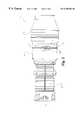
- FIG. 2is an enlarged partially fragmented side elevational view of the gas turbine engine of FIG. 1 .
- FIG. 3is a partial perspective view of one embodiment of a seal system comprising a portion of the FIG. 2 gas turbine engine.
- FIG. 4is a perspective view of one embodiment of the turbine blade with an abrasive cermet tip comprising a portion of the FIG. 3 seal system.
- FIG. 5is a partially exploded view of an alternate embodiment of the gas turbine blade with an abrasive cermet tip.
- FIG. 6is an illustrative view of one embodiment of the direct laser processing workstation of the present invention.
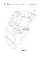
- FIG. 7is a partially fragmented view of the direct laser processing workstation of FIG. 6 .
- FIG. 8is a schematic view of the portion of the FIG. 6 apparatus which controls the direction of the laser beam within the direct laser processing workstation.
- FIG. 9is an illustrative diagram of of the FIG. 5 abrasive cermet blade tip of FIG. 5 formed in the powder parts bed comprising a portion of FIG. 7 .
- FIG. 10is an illustrative view of a laser scan path for the processing of one embodiment of the abrasive cermet blade tips.
- FIG. 11 arepresents a portion of the unmelted material constituents that are utilized in the direct laser process.
- FIG. 11 brepresents a portion of the material of FIG. 11 a that has been melted and allowed to solidify by the direct laser process.
- an aircraft 10including an aircraft flight propulsion engine 11.
- the flight propulsion engine 11includes a compressor 12 , a combustor 13 and a power turbine 14 . It is important to realize that there are a multitude of ways in which the components can be linked together. Additional compressors and turbines can be added with intercoolers connected between the compressors and reheat combustion chambers could be added between the turbines. Further, the gas turbine engine is equally suited to be used for industrial applications. Historically, there has been the widespread application of industrial gas turbine engines, such as pumping sets for gas and oil transmission lines, electricity generation and naval propulsion.
- FIG. 2there is illustrated the enlarged partially fragmented view of the gas turbine engine 11 .
- the gas turbine engine 11having a rotor disk 17 , with a plurality of turbine blades 16 mounted thereto, that is coupled to a shaft (not illustrated) within the gas turbine engine 11 .
- a plurality of turbine vanes 16 aform a nozzle within the gas turbine engine for directing the flow of working fluid relative to the blades 16 .
- the working fluidis air extracted from the compressor 12 .
- the sealing system 20is designed to minimize the leakage of working fluid away from and around the working fluid path.
- the efficiency of the gas turbine engineis dependent upon the ability to control and minimize the leakage of this working fluid.
- the clearance between the tip 19 of the turbine blade 16 and the static structure 22 of the gas turbine engineassists in controlling the bypassing of the rotor 17 and turbine blades 16 by the working fluid.
- Clearance between the rotating and static components ( 21 and 23 respectively)changes with the expansion and contraction of the components due to the thermal cycling occurring in the gas turbine engine.
- the sealing system 20comprises the two corresponding components that form a virtual seal between the rotating and static components.
- the two componentsare an abrasive component 21 that is coupled to the turbine blade 16 , and a stationary abradable component 23 which is coupled to the stationary component 22 .
- the stationary abradable component 23is often referred to as a shroud and is a member that circumscribes the rotor disk 17 and blades 16 while covering a portion of the stationary component 22 .
- the turbine blade 16 with abrasive component 21rotates relative to the abradable component 23 to wear-form a virtual seal track in the abradable component 23 .
- the rotation of the rotor disk 17 with turbine blades 16 coupled theretoallows the abrasive components 21 to abrade the abradable component 23 when there is no clearance between the respective components.
- a particular aspect of the abrasive component 21is the ability to withstand repeated and severe encounters with the abradable component 23 with only minimal loss of material from the abrasive component 21 and preferential wear of the abradable component 23 .
- the abrasive component 21cuts the abradable component 23 to maintain a minimum clearance therebetween.
- the abrasion of the abradable component 23 by the rotating abrasive component 21forms a fluid passageway between the rotating components.
- the abradable component 23is a semi-porous abradable ceramic that is generally known to those of ordinary skill in the art.
- the turbine blade 16can be of a wrought or cast structure.
- the gas turbine blade 16is a unitary cast alloy structure produced by a precision casting operation utilizing various super alloy compositions.
- various types of nickel, titanium, and cobalt super alloy compositions and manufacturers of such compositionsare known to those skilled in the art.
- Most super alloy compositions of interestare complicated mixtures of either titanium, tin, vanadium, aluminum, molybdenum, silicon, neodymium and other select materials; or nickel, cobalt, chromium, aluminum, titanium, iron, tungsten, tantalum, rhenium and other select elements.
- a preferred group of materialsare generally known by the following tradenames CMSX-3, CMSX-4 and MARM-247, and are readily available and known to people of ordinary skill in the art. However, the application of the present invention is not intended herein to be limited to the above materials, and can be utilized with other materials.
- a technique for producing a cast unitary turbine blade 16 having equiaxed, directionally solidified or single crystal alloy structuresis disclosed in U.S. Pat. No. 5,295,530 to O'Connor which is incorporated by reference herein.
- a gas turbine blade and a gas turbine vaneare often referred to as an airfoil.
- the abrasive component 21is metallurgically bonded to the blade 16 without the presence of a brazing element or other lower melting temperature joining materials. Elimination of the low melting point braze element produces a brazeless cermet having an extended oxidation life and the capability to withstand exposure to higher operating temperatures than components having the braze element.
- the abrasive component 21comprising an abrasive cermet composition which includes a metal powder superalloy matrix combined with ceramic abrasive particles.
- the ceramic abrasive particlesare coated with a reactive material, and in a second form of the present invention the ceramic abrasive particles are not coated with a reactive material.
- the material compositioncomprises about 0 wt.
- the ceramic abrasive particlesbeing of a ceramic grit material, and more preferably of at least one of the following: cubic boron nitride; man made diamond; silicon carbide; and aluminum oxide. Further, one embodiment of the present invention contemplates a mixture of at least two of the ceramic grit materials. A more preferred form of the present invention utilizes a mixture of cubic boron nitride and aluminum oxide. In one embodiment the ceramic abrasive particles having a grit size in the range between 80 mesh size and 120 mesh size.
- the reactive materialis preferably titanium which serves to wet the surface of the ceramic abrasive coating to promote a metallurgical bond between the particles and the metal matrix.
- the titanium coatinghas preferably been applied using known fluid bed chemical vapor deposition techniques so as to ensure uniformity of the coating on the particles. However, other suitable processes known in the art are acceptable.
- the ceramic abrasive particlesmay be homogenous or graded through any portion of the component.
- the bed of material that forms the abrasive component 21is subjected to a direct through thickness laser processing which causes the metal matrix material to become molten, solidify and bond with the turbine blade 16 .
- Direct laser processingis a manufacturing technique for fabricating parts from a powder bed, and details pertaining to the direct laser process utilized to make the abrasive tipped blade 16 are provided below. This method is applicable to an entire region of material, a select region of material, and for cutting portions of the component.
- the direct tipping of the blade with the abrasive component 21 through the direct laser processproduces a component free of the life degradation that results from many prior art methods that includes the addition of melting point depressants typically present in braze alloys and/or that require exposing the components to a high temperature brazing and/or a diffusion bonding thermal cycle which degrades the morphology of the strengthing phase.
- FIG. 5there is illustrated an alternate embodiment of the gas turbine engine blade 160 with an abrasive cermet component 210 coupled thereto by a secondary joining operation.
- the secondary joining operationis generally a brazing operation utilizing a brazing material 211 that couples the abrasive component 210 to the blade 16 .
- the abrasive component 210is fabricated by the direct laser process that is used to produce the abrasive component 21 . Thereafter the abrasive component 210 is joined to blade 160 with the brazing material 211 .
- Apparatus 25for performing the direct laser processing of a powder bed of material (not illustrated) in order to produce a free form fabrication.
- the term free form fabrication as used hereinincludes, unless otherwise specified, the capability to make a solid and/or hollow part.
- Apparatus 25includes a chamber 26 within which the direct laser process takes place, and a laser 28 for performing the melting of the material that is then allowed to solidify.
- the chamber 26is defined by a fluid tight pressure vessel with a vacuum pumping system 27 coupled thereto for changing the atmosphere within the chamber, and a heat source capable of heating the powder bed of material 30 (FIG. 7) to elevated temperatures. Preheating of the powder material bed 30 prior to the laser beam melting and solidifying aids in the outgassing of the material and improves surface characteristics, wetting and flow.
- Chamber 26is designed and constructed so as to be capable of maintaining a high purity atmosphere of select gases.
- the heat sourcemay be located internal or external to the chamber 26 and is capable of accurately heating and controlling the powder bed to temperatures within the range from ambient to 2000 degrees centigrade, while the vacuum source is capable of providing a high vacuum.
- the laser melting and solidifying of the materialoccur when the material bed is at an elevated temperature thereby improving dimensional stability.
- temperatures within the range of about 500 degrees centigrade to 750 degrees centigradeare preferred for the material bed during the direct laser processing-melting and solidification stages.
- temperatures greater than 750 degrees centigradeare preferred for the material bed during the laser processing.
- the vacuumpreferably being in the range of about 5 ⁇ 10 ⁇ 3 Torr to about 1 ⁇ 10 ⁇ 7 Torr, and more preferably is about 5 ⁇ 10 ⁇ 5
- other pressuresare contemplated herein.
- the chamber 26could be thought of as being analagous to a vacuum furnace that can be adjusted to provide a tightly controlled atmosphere within the chamber.
- the control of the atmosphereis characterized by the ability to regulate the chemical makeup of the gas within the chamber, degree of vacuum, and temperature.
- an inert atmosphereis utilized to suppress the volatilization of the material constituents within the chamber 26 .
- the laser 28provides a beam that selectively melts and allows the resolidification of the material within the chamber 26 .
- Other means for melting the material contemplated hereinincludes but is not limited to ultrasound, x-ray, and microwave.
- the chamber 216has a sealed laser transparent window 29 for allowing the passage of the laser beam therethrough. Laser transparent windows are believed known to persons of ordinary skill in the art.
- Another form of the present inventionincludes a disposable or indexable laser transmission window apparatus to compensate for window clouding and deposits. Thereby allowing the ready return to a more completely transparent laser transmission window for facilitating process control and reproducability.
- the means for melting the materialcould be confined within the chamber 26 , the means could be external to the chamber and passable through an opening in the chamber, and/or delivered through a medium coupled to the chamber such as a fiber optic cable.
- chamber 26With reference to FIG. 7, there is illustrated chamber 26 with a portion removed for purposes of clarity. Positioned within the chamber 26 is a powder bed of material 30 for melting with the laser beam.
- the material holder 31is illustrated as a tray, however other types of material holders are contemplated herein.
- the material holderfixtures a turbine blade so that the abrasive cermet composite may be directly melted, solidified and bonded on the blade, thereby producing a directly tipped blade. It is understood herein that in one embodiment of the present invention the powder bed of material 30 is not bonded to the material holder 31 .
- a memberis positioned on the material holder so that the powder bed of material can be bonded thereto, and another form of the present invention has the powder bed directly bonded to the material holder.
- Another, form of the present inventionallows the holding of a component (such as a tool, blade, etc) at various inclinations so as to orient the component for localized repair within the chamber 26 .
- the repair of the componentinvolves the localized heating of the component that is at ambient or near ambient temperatures.
- the localized heatingis done by means such as inductive, electron beam, laser, plasma, focused lamps and/or other suitable means for controlled localized heating.
- the material holders of the present inventionare designed and constructed to withstand the preheat temperatures that the powder beds 30 are subjected to.
- a preferred laser for direct laser processingis a Nd:YAG laser having sufficient power to melt a portion of material bed. Both single pass through thickness melting of the material, and double pass through thickness melting of the material bed are contemplated herein. However, other types of lasers and different power levels are within the contemplation of the present invention.
- One embodiment of the present inventionutilizes a 250 watt laser. The control of a laser is believed within the contemplation of a person of ordinary skill in the art and the particular laser apparatus control scheme disclosed herein is not meant to limit the present methods and apparatus for making components by direct laser processing.
- Laser head 28thus includes such conventional control elements as described in U.S. Pat. No. 4,863,538, and U.S. Pat. No. 5,156,697; for example a safety shutter, a front mirror assembly, and focusing elements such as diverging and converging lenses.
- a computer 31 and scanning system 32are also included for controlling the direction of the laser beam as it impinges upon the powder bed 30 .
- computer 31includes a microprocessor for controlling laser 28 , and further includes a CAD/CAM system for generating the data by which the dimensions of the part to be produced is defined. However, other methods to generate the data to define the parts dimensions are contemplated herein.
- the laser scanning position and scan speedare controlled by the computer software.
- Scanning system 32includes prism 33 for redirecting the path of travel of the laser beam.
- the number of prisms necessary for directing the laser beam to the desired locationis based on the physical layout of the apparatus.
- one or more fixed mirrorscan be used in place of prism 33 for directing the laser beam from the laser 28 to the scanning system 32 , depending upon the particular layout of the equipment.
- Scanning system 32further includes a pair of mirrors 34 , 35 which are driven by respective galvanometers 36 , 37 .
- Galvanometers 36 , 37are coupled to their respective mirrors 34 , 35 to selectively orient the mirrors 34 , 35 and control the aim of the laser beam.
- Galvanometers 36 , 37are mounted perpendicularly to one another so that mirrors 34 , 35 are mounted nominally at a right angle relative to one another.
- a function generator drivercontrols the movement of galvanometers 36 , 37 to control the aim of the laser beam on the powder bed 30 , and in conjunction with computer 31 .
- the function generator driveris coupled to computer 31 , so that the CAD/CAM data within the computer can be realized in the directional control of the laser beam via mirrors 34 , 35 .
- alternative scanning systemsmay be used such as acousto-optic scanners, rotating polygonal mirrors, and resonant mirror scanners.
- FIG. 9there is illustrated an illustrative plan view of a pair of abrasive cermet components 21 formed in the powder bed 30 .
- the abrasive cermet components 30 formed by the direct laser processing of the material within, the powder bed 30are them coupled to the turbine blade 16 .
- FIG. 10An enlarged illustrative view of a laser beam scanning sequence is set forth in FIG. 10 .
- Laser scanning sequencesare dependent upon the part geometry and the scanning sequence affects the thermal profile of the part.
- One method of achieving a uniform thermal profileis by the selection of appropriate laser scan speed, scan spacing, and laser beam energy for the individual scan length vector.
- a scan length vectordefines a portion of the component that will be subjected to a particular pass of the laser beam.
- the scan spacingis preferred less than 0.100 inches, and the scan spacing is more preferred to be in the range of about 0.0001 inches to about 0.0003 inches.
- FIGS. 1-10With the assistance of FIGS. 1-10, there has been provided a description of the method and apparatus to produce a direct laser processed component. More particularly, a description of forming an abrasive cermet component has been set forth, however other components can be fabricated with the present invention. A more detailed description of the process of forming a component by direct laser processing will now be set forth with the aid of FIGS. 1-11.
- the direct laser processis a procedure in which the material constituents of the powder bed are directly laser melted and consolidated to produce a solidified part requiring little or no post processing.
- the constituents that were not meltedare reusable thereby minimizing the amount of scrap and wasted raw material generated in the process.
- the components formedare substantially free of voids and cracks and can be fabricated so as to be near net shape.
- the components microstructureis modified by a post process heat treatment.
- the direct laser processcan have parameters adjusted so as produce a highly dense part or a porous part. Further, the process can be used to produce composite components such as cermet abrasive components and/or full density monolithic metallic components.
- a component fabricated of abrasive cermet materialhas a size less than about four inches in diameter and a thickness less than about 0.100 inches.
- a component fabricated from abrasive cermet material having a thickness in the range of about 0.035 to about 0.060 inchesis more preferred, and a component fabricated from abrasive cermet material having a thickness of about 0.060 inches is most preferred.
- Monolithic metallic components having a size less than four inches in diameter and a thickness of up to four inchesare contemplated herein.
- the monolithic metallic components having a thickness greater than 0.100 inchesare fabricated by melting the first powder bed layer and them melting additional layers of powder placed over the first previously melted layer of powder.
- a more preferred form of the monolithic metallic componenthas a thickness of about 0.100 inches.
- components formed by the direct laser processing which have a laminar structureare contemplated herein.
- FIGS. 11 a & 11 bthere is illustrated the melting and solidification of the metal matrix component constituents 75 of the abrasive cermet composite material.
- the laser beammelts the metal matrix composite so as to obtain the appropriate amount of flow from the molten material.
- the appropriate amount of flowis qualitatively defined as the amount of flow necessary to eliminate porosity, producing a high density part while maintaining high dimensional precision and minimizing tearing.
- the control of the amount of flowis dependent upon many parameters including the atmosphere in which the melting and solidification occurs, degree of preheat of the material powder bed, and characteristics affecting laser energy density such as laser power, scan spacing and scan speed.
- the desire to have a uniform thermal profileimplies that a very fine scan spacing with a high scan speed are preferred.
- the selection of scan speed and scan spacinghave a direct affect on the surface roughness of the resulting component.
- a fine scan spacingwill provide a relatively uniform smooth surface, whereas scan speed effects on surface roughness are dependent upon the overall energy density and the associated residence time in the molten material region.
- For a given materiala high scan speed with a high energy density which would produce a long residence molten time will produce a poor surface finish.
- the same scan speed with a lower energy densitywill produce a better surface finish.
- the test data for for the cermet compositeindicated that full through thickness melting was achieved with energy densities of approximately 1900 joules/cm 2 .
- the sample of cermet compositeincluded 73.5 wt. % metal alloy, and 26.5 wt. % abrasive grit coating. More preferably the metal alloy was a MarM247.
- the abrasive grit coatingcomprises an abrasive grit material with about a 2.5 wt. % to 12 wt. % titanium coating forming a uniform coating on all surfaces of the particles.
- the samplesillustrated porosity entraped around the grit particle 76 (FIGS.
- the production of a component by direct laser processingbegins by blending the material components together.
- the materialis blended for 4-6 hours prior to placing in the chamber 26 .
- the materialis then preheated for a period of time to preprocess the material.
- the preheatingoccurs within the chamber 25 .
- the environment within the chamber 26is adjusted and the bed of material 30 is subjected to the direct laser processing.
- the direct laser processingoccurs while the bed of material 30 is at an elevated temperature so as to enhance dimensional stability.
- the component formedhas a structure consistent with a metallurgical casting with a refined microstructure. Further, the microstructure refinement is dependent upon the energy density, atmosphere, and preheating that the material bed 30 was subjected to.
- control of the energy density in this processwill enable region specific microstructure control, thereby enabling a part to have multiple microstructures ranging from equiaxed to dendritic.
- the componentmay have regions containing equiaxed, dendritic, directionally solidified, and/or single crystal.
Landscapes
- Engineering & Computer Science (AREA)
- Physics & Mathematics (AREA)
- Plasma & Fusion (AREA)
- Chemical & Material Sciences (AREA)
- Manufacturing & Machinery (AREA)
- Materials Engineering (AREA)
- Mechanical Engineering (AREA)
- General Engineering & Computer Science (AREA)
- Laser Beam Processing (AREA)
Abstract
Description
| Energy | ||||
| Temperature | Laser Power | Scan Spacing | Scan Speed | Density |
| (° C.) | (Watts) | (in.) | (in./s) | (J/cm2) |
| 300 | 115 | .000166 | 33 | 3202 |
| 300 | 80 | .000166 | 39 | 2088 |
| 450 | 130 | .000166 | 33 | 3678 |
| 55o | 145 | .000166 | 33 | 4102 |
| 615 | 135 | .000166 | 33 | 3819 |
| 750 | 135 | .000275 | 30 | 2495 |
| 750 | 200 | .000275 | 30 | 3696 |
| 860 | 97.5 | .000156 | 61 | 1588 |
| 860 | 150 | .000156 | 61 | 2443 |
| 860 | 105 | .000156 | 99 | 1052 |
| 860 | 110 | .000156 | 109 | 1000 |
| 860 | 97.5 | .000156 | 64 | 1525 |
| 900 | 150 | .000275 | 61 | 1386 |
Claims (32)
Priority Applications (1)
| Application Number | Priority Date | Filing Date | Title |
|---|---|---|---|
| US08/910,044US6355086B2 (en) | 1997-08-12 | 1997-08-12 | Method and apparatus for making components by direct laser processing |
Applications Claiming Priority (1)
| Application Number | Priority Date | Filing Date | Title |
|---|---|---|---|
| US08/910,044US6355086B2 (en) | 1997-08-12 | 1997-08-12 | Method and apparatus for making components by direct laser processing |
Publications (2)
| Publication Number | Publication Date |
|---|---|
| US20010014403A1 US20010014403A1 (en) | 2001-08-16 |
| US6355086B2true US6355086B2 (en) | 2002-03-12 |
Family
ID=25428224
Family Applications (1)
| Application Number | Title | Priority Date | Filing Date |
|---|---|---|---|
| US08/910,044Expired - LifetimeUS6355086B2 (en) | 1997-08-12 | 1997-08-12 | Method and apparatus for making components by direct laser processing |
Country Status (1)
| Country | Link |
|---|---|
| US (1) | US6355086B2 (en) |
Cited By (54)
| Publication number | Priority date | Publication date | Assignee | Title |
|---|---|---|---|---|
| US20030214083A1 (en)* | 2002-02-14 | 2003-11-20 | Kelly William G.H. | Method of making topographical support members for producing apertured films |
| US6676892B2 (en)* | 2000-06-01 | 2004-01-13 | Board Of Regents, University Texas System | Direct selective laser sintering of metals |
| US20040033311A1 (en)* | 2002-03-09 | 2004-02-19 | Erwin Bayer | Method for removing coating from power unit components and device for carrying out the method |
| EP1400339A1 (en)* | 2002-09-17 | 2004-03-24 | Siemens Aktiengesellschaft | Method for manufacturing a three-dimensional object |
| US20040191106A1 (en)* | 2002-11-08 | 2004-09-30 | Howmedica Osteonics Corp. | Laser-produced porous surface |
| US6933061B2 (en) | 2002-12-12 | 2005-08-23 | General Electric Company | Thermal barrier coating protected by thermally glazed layer and method for preparing same |
| US20060147332A1 (en)* | 2004-12-30 | 2006-07-06 | Howmedica Osteonics Corp. | Laser-produced porous structure |
| US20060231535A1 (en)* | 2005-04-19 | 2006-10-19 | Fuesting Timothy P | Method of welding a gamma-prime precipitate strengthened material |
| US20070034048A1 (en)* | 2003-01-13 | 2007-02-15 | Liu Shaiw-Rong S | Hardmetal materials for high-temperature applications |
| US20070119276A1 (en)* | 2005-03-15 | 2007-05-31 | Liu Shaiw-Rong S | High-Performance Friction Stir Welding Tools |
| US20080004709A1 (en)* | 2005-12-30 | 2008-01-03 | Howmedica Osteonics Corp. | Laser-produced implants |
| US20080257107A1 (en)* | 2003-01-13 | 2008-10-23 | Genius Metal, Inc. | Compositions of Hardmetal Materials with Novel Binders |
| US20090255262A1 (en)* | 2008-04-11 | 2009-10-15 | General Electric Company | Fuel nozzle |
| US20090255120A1 (en)* | 2008-04-11 | 2009-10-15 | General Electric Company | Method of assembling a fuel nozzle |
| US20090255256A1 (en)* | 2008-04-11 | 2009-10-15 | General Electric Company | Method of manufacturing combustor components |
| US20090255261A1 (en)* | 2008-04-11 | 2009-10-15 | Mcmasters Marie Ann | Method of manufacturing a unitary venturi |
| US20090255264A1 (en)* | 2008-04-11 | 2009-10-15 | General Electric Company | Fuel nozzle |
| US20090280269A1 (en)* | 2005-06-30 | 2009-11-12 | General Electric Company | Niobium silicide-based turbine components, and related methods for laser deposition |
| US20100173094A1 (en)* | 2007-05-04 | 2010-07-08 | Mtu Aero Engines Gmbh | Method for manufacturing an abrasive coating on a gas turbine companent |
| US20100180514A1 (en)* | 2003-01-13 | 2010-07-22 | Genius Metal, Inc. | High-Performance Hardmetal Materials |
| US20110052412A1 (en)* | 2006-10-18 | 2011-03-03 | Mtu Aero Engines Gmbh | High-pressure turbine rotor, and method for the production thereof |
| EP2317075A2 (en) | 2009-10-30 | 2011-05-04 | Alstom Technology Ltd | Method for repairing a gas turbine component |
| US20110099809A1 (en)* | 2009-10-30 | 2011-05-05 | Hoevel Simone | Methods for repairing a gas turbine component |
| US20110106290A1 (en)* | 2009-10-30 | 2011-05-05 | Hoevel Simone | Method of applying multiple materials with selective laser melting on a 3d article |
| US20110135489A1 (en)* | 2009-12-08 | 2011-06-09 | Honeywell International Inc. | Nickel-based superalloys, turbine blades, and methods of improving or repairing turbine engine components |
| US20110235199A1 (en)* | 2007-06-26 | 2011-09-29 | Dave Keicher | Prism mount for a laser deposition device |
| US8142886B2 (en) | 2007-07-24 | 2012-03-27 | Howmedica Osteonics Corp. | Porous laser sintered articles |
| US8147861B2 (en) | 2006-08-15 | 2012-04-03 | Howmedica Osteonics Corp. | Antimicrobial implant |
| US20120107496A1 (en)* | 2010-05-05 | 2012-05-03 | Eos Gmbh Electro Optical Systems | Method of generatively manufacturing a three-dimensional object with broaching elements and method of generating a corresponding data set |
| EP2484481A1 (en) | 2011-02-03 | 2012-08-08 | Alstom Technology Ltd | Method for repairing or reconditioning a badly damaged component, in particular from the hot gas region of a gas turbine |
| US20130156586A1 (en)* | 2010-08-14 | 2013-06-20 | Karl-Hermann Richter | Method for connecting a turbine blade or vane to a turbine disc or a turbine ring |
| US8556981B2 (en) | 2005-12-06 | 2013-10-15 | Howmedica Osteonics Corp. | Laser-produced porous surface |
| US20150093237A1 (en)* | 2013-09-30 | 2015-04-02 | General Electric Company | Ceramic matrix composite component, turbine system and fabrication process |
| US20150125335A1 (en)* | 2013-11-05 | 2015-05-07 | Gerald J. Bruck | Additive manufacturing using a fluidized bed of powdered metal and powdered flux |
| US9135374B2 (en) | 2012-04-06 | 2015-09-15 | Howmedica Osteonics Corp. | Surface modified unit cell lattice structures for optimized secure freeform fabrication |
| US20150315090A1 (en)* | 2014-05-01 | 2015-11-05 | Siemens Energy, Inc. | Laser glazing using hollow objects for shrinkage compliance |
| US9180010B2 (en) | 2012-04-06 | 2015-11-10 | Howmedica Osteonics Corp. | Surface modified unit cell lattice structures for optimized secure freeform fabrication |
| US9364896B2 (en) | 2012-02-07 | 2016-06-14 | Medical Modeling Inc. | Fabrication of hybrid solid-porous medical implantable devices with electron beam melting technology |
| US20160237831A1 (en)* | 2015-02-12 | 2016-08-18 | United Technologies Corporation | Abrasive blade tip with improved wear at high interaction rate |
| US9776282B2 (en) | 2012-10-08 | 2017-10-03 | Siemens Energy, Inc. | Laser additive manufacture of three-dimensional components containing multiple materials formed as integrated systems |
| US20170297323A1 (en)* | 2016-04-15 | 2017-10-19 | Machine Tool Technologies Research Foundation | Method for generating control data, data processing device, machine tool, and program |
| US10150184B2 (en) | 2015-10-21 | 2018-12-11 | Siemens Energy, Inc. | Method of forming a cladding layer having an integral channel |
| US10190774B2 (en) | 2013-12-23 | 2019-01-29 | General Electric Company | Fuel nozzle with flexible support structures |
| US10253417B2 (en) | 2017-01-30 | 2019-04-09 | United Technologies Corporation | System and method for applying abrasive grit |
| US10288293B2 (en) | 2013-11-27 | 2019-05-14 | General Electric Company | Fuel nozzle with fluid lock and purge apparatus |
| US10343392B2 (en) | 2015-08-27 | 2019-07-09 | General Electric Company | Powder-bed additive manufacturing devices and methods |
| US10451282B2 (en) | 2013-12-23 | 2019-10-22 | General Electric Company | Fuel nozzle structure for air assist injection |
| US10569362B2 (en) | 2013-11-14 | 2020-02-25 | General Electric Company | Layered manufacturing of single crystal alloy components |
| US10710161B2 (en)* | 2013-03-11 | 2020-07-14 | Raytheon Technologies Corporation | Turbine disk fabrication with in situ material property variation |
| US11000899B2 (en) | 2012-01-29 | 2021-05-11 | Raytheon Technologies Corporation | Hollow airfoil construction utilizing functionally graded materials |
| US11078588B2 (en) | 2017-01-09 | 2021-08-03 | Raytheon Technologies Corporation | Pulse plated abrasive grit |
| US11084096B2 (en) | 2017-08-17 | 2021-08-10 | General Electric Company | Movable wall for additive powder bed |
| WO2021213735A1 (en) | 2020-04-24 | 2021-10-28 | Rolls-Royce Deutschland Ltd & Co Kg | Abrasive material, a method for manufacturing an abrasive material and a substrate coated with an abrasive material |
| US11298747B2 (en) | 2017-05-18 | 2022-04-12 | Howmedica Osteonics Corp. | High fatigue strength porous structure |
Families Citing this family (39)
| Publication number | Priority date | Publication date | Assignee | Title |
|---|---|---|---|---|
| CH696854A5 (en) | 2003-04-14 | 2007-12-31 | Alstom Technology Ltd | Thermal turbomachinery. |
| DE10319494A1 (en)* | 2003-04-30 | 2004-11-18 | Mtu Aero Engines Gmbh | Process for repairing and / or modifying components of a gas turbine |
| DE102005002609A1 (en)* | 2005-01-20 | 2006-08-03 | Mtu Aero Engines Gmbh | Method of repairing turbine blades |
| GB0504576D0 (en)* | 2005-03-05 | 2005-04-13 | Alstom Technology Ltd | Turbine blades and methods for depositing an erosion resistant coating on the same |
| GB0601982D0 (en)* | 2006-02-01 | 2006-03-15 | Rolls Royce Plc | Method and apparatus for examination of objects and structures |
| DE102006044555A1 (en)* | 2006-09-21 | 2008-04-03 | Mtu Aero Engines Gmbh | repair procedures |
| DE102006049219A1 (en)* | 2006-10-18 | 2008-04-30 | Mtu Aero Engines Gmbh | High pressure turbine blade and method of repairing high pressure turbine blades |
| DE602006014283D1 (en)* | 2006-11-22 | 2010-06-24 | Siemens Ag | Method of brazing a honeycomb seal in a turbine |
| DE102006058949A1 (en) | 2006-12-14 | 2008-06-19 | Inno-Shape Gmbh | Device and method for repairing or producing blade tips of blades of a gas turbine, in particular an aircraft engine |
| EP2279499B1 (en)* | 2008-04-14 | 2016-11-23 | Rolls-Royce Corporation | Method for producing ceramic stereolithography parts |
| US8510925B2 (en)* | 2008-09-04 | 2013-08-20 | Rolls-Royce Corporation | System and method for sealing vacuum in hollow fan blades |
| GB0816308D0 (en) | 2008-09-05 | 2008-10-15 | Mtt Technologies Ltd | Optical module |
| EP2317079B1 (en)* | 2009-10-30 | 2020-05-20 | Ansaldo Energia Switzerland AG | Abradable coating system |
| EP2359964B1 (en) | 2010-01-26 | 2013-11-20 | Alstom Technology Ltd | Process for Producing a 3-Dimensional Component by Means of Selective Laser Melting (SLM) |
| US9175568B2 (en) | 2010-06-22 | 2015-11-03 | Honeywell International Inc. | Methods for manufacturing turbine components |
| EP2415552A1 (en)* | 2010-08-05 | 2012-02-08 | Siemens Aktiengesellschaft | A method for manufacturing a component by selective laser melting |
| US9085980B2 (en) | 2011-03-04 | 2015-07-21 | Honeywell International Inc. | Methods for repairing turbine components |
| US8691333B2 (en)* | 2011-06-28 | 2014-04-08 | Honeywell International Inc. | Methods for manufacturing engine components with structural bridge devices |
| FR2978070B1 (en)* | 2011-07-22 | 2014-11-14 | Snecma | PROCESS FOR REPAIRING A TURBOMACHINE PIECE |
| US8506836B2 (en) | 2011-09-16 | 2013-08-13 | Honeywell International Inc. | Methods for manufacturing components from articles formed by additive-manufacturing processes |
| US9266170B2 (en)* | 2012-01-27 | 2016-02-23 | Honeywell International Inc. | Multi-material turbine components |
| US9120151B2 (en) | 2012-08-01 | 2015-09-01 | Honeywell International Inc. | Methods for manufacturing titanium aluminide components from articles formed by consolidation processes |
| GB201213940D0 (en) | 2012-08-06 | 2012-09-19 | Materials Solutions | Additive manufacturing |
| JP6342912B2 (en)* | 2012-11-08 | 2018-06-13 | ディーディーエム システムズ, インコーポレイテッド | Additive manufacturing and repair of metal components |
| WO2014131444A1 (en)* | 2013-02-27 | 2014-09-04 | Slm Solutions Gmbh | Apparatus and method for producing work pieces having a tailored microstructure |
| EP2781691A1 (en)* | 2013-03-19 | 2014-09-24 | Alstom Technology Ltd | Method for reconditioning a hot gas path part of a gas turbine |
| US10562132B2 (en)* | 2013-04-29 | 2020-02-18 | Nuburu, Inc. | Applications, methods and systems for materials processing with visible raman laser |
| US9822264B2 (en) | 2013-07-15 | 2017-11-21 | United Technologies Corporation | Nanocellular and nanocellular particle filled polymer composite coating for erosion protection |
| EP2857177A1 (en)* | 2013-10-01 | 2015-04-08 | Siemens Aktiengesellschaft | Method for layered construction of a three-dimensional component and device for performing the method |
| US9909428B2 (en) | 2013-11-26 | 2018-03-06 | General Electric Company | Turbine buckets with high hot hardness shroud-cutting deposits |
| CN108463300A (en) | 2015-11-16 | 2018-08-28 | 瑞尼斯豪公司 | Module for increasing material manufacturing device and method |
| US20180093418A1 (en) | 2016-09-30 | 2018-04-05 | Velo3D, Inc. | Three-dimensional objects and their formation |
| EP3450684A1 (en) | 2017-09-04 | 2019-03-06 | Siemens Aktiengesellschaft | Method of manufacturing a component |
| US20190211457A1 (en)* | 2018-01-05 | 2019-07-11 | United Technologies Corporation | Method for applying an abrasive tip to a high pressure turbine blade |
| JP7253571B2 (en)* | 2018-05-09 | 2023-04-06 | フラウンホッファー-ゲゼルシャフト ツァ フェルダールング デァ アンゲヴァンテン フォアシュンク エー.ファオ | Mirror support for composite optical mirror and manufacturing method thereof |
| CA3148849A1 (en) | 2019-07-26 | 2021-02-04 | Velo3D, Inc. | Quality assurance in formation of three-dimensional objects |
| US11612986B2 (en)* | 2019-12-17 | 2023-03-28 | Rolls-Royce Corporation | Abrasive coating including metal matrix and ceramic particles |
| US11958246B2 (en)* | 2020-03-03 | 2024-04-16 | Sciperio, Inc | Laser oven with transparent chamber and external laser source |
| CN114150310A (en)* | 2021-12-10 | 2022-03-08 | 哈尔滨阿尔特机器人技术有限公司 | Preparation method of high temperature wear-resistant layer on surface of blade crown of turbine blade |
Citations (44)
| Publication number | Priority date | Publication date | Assignee | Title |
|---|---|---|---|---|
| US4169020A (en) | 1977-12-21 | 1979-09-25 | General Electric Company | Method for making an improved gas seal |
| US4222706A (en) | 1977-08-26 | 1980-09-16 | Societe Nationale D'etude Et De Construction De Moteurs D'aviation | Porous abradable shroud with transverse partitions |
| US4232995A (en) | 1978-11-27 | 1980-11-11 | General Electric Company | Gas seal for turbine blade tip |
| US4377371A (en) | 1981-03-11 | 1983-03-22 | The United States Of America As Represented By The Administrator Of The National Aeronautics And Space Administration | Laser surface fusion of plasma sprayed ceramic turbine seals |
| US4589823A (en) | 1984-04-27 | 1986-05-20 | General Electric Company | Rotor blade tip |
| US4610698A (en) | 1984-06-25 | 1986-09-09 | United Technologies Corporation | Abrasive surface coating process for superalloys |
| US4611744A (en) | 1982-06-23 | 1986-09-16 | Refurbished Turbine Components Ltd. | Turbine blade repair |
| US4627896A (en)* | 1984-07-16 | 1986-12-09 | Bbc Brown, Boveri & Company Limited | Method for the application of a corrosion-protection layer containing protective-oxide-forming elements to the base body of a gas turbine blade and corrosion-protection layer on the base body of a gas turbine blade |
| US4675204A (en) | 1984-07-17 | 1987-06-23 | Bbc Aktiengesellschaft Brown, Boveri & Cie | Method of applying a protective layer to an oxide dispersion hardened superalloy |
| US4680199A (en) | 1986-03-21 | 1987-07-14 | United Technologies Corporation | Method for depositing a layer of abrasive material on a substrate |
| US4689242A (en) | 1986-07-21 | 1987-08-25 | United Technologies Corporation | Method for adhesion of grit to blade tips |
| US4735656A (en)* | 1986-12-29 | 1988-04-05 | United Technologies Corporation | Abrasive material, especially for turbine blade tips |
| US4744725A (en) | 1984-06-25 | 1988-05-17 | United Technologies Corporation | Abrasive surfaced article for high temperature service |
| US4802828A (en) | 1986-12-29 | 1989-02-07 | United Technologies Corporation | Turbine blade having a fused metal-ceramic tip |
| US4808055A (en) | 1987-04-15 | 1989-02-28 | Metallurgical Industries, Inc. | Turbine blade with restored tip |
| US4818833A (en) | 1987-12-21 | 1989-04-04 | United Technologies Corporation | Apparatus for radiantly heating blade tips |
| US4851188A (en) | 1987-12-21 | 1989-07-25 | United Technologies Corporation | Method for making a turbine blade having a wear resistant layer sintered to the blade tip surface |
| US4854196A (en) | 1988-05-25 | 1989-08-08 | General Electric Company | Method of forming turbine blades with abradable tips |
| US4863538A (en) | 1986-10-17 | 1989-09-05 | Board Of Regents, The University Of Texas System | Method and apparatus for producing parts by selective sintering |
| US4884820A (en) | 1987-05-19 | 1989-12-05 | Union Carbide Corporation | Wear resistant, abrasive laser-engraved ceramic or metallic carbide surfaces for rotary labyrinth seal members |
| US4938916A (en) | 1982-12-13 | 1990-07-03 | Ltv Aerospace And Defense Co. | Flux enhancement for neutron radiography inspection device |
| US4944817A (en) | 1986-10-17 | 1990-07-31 | Board Of Regents, The University Of Texas System | Multiple material systems for selective beam sintering |
| US5045972A (en)* | 1990-08-27 | 1991-09-03 | The Standard Oil Company | High thermal conductivity metal matrix composite |
| US5048183A (en) | 1988-08-26 | 1991-09-17 | Solar Turbines Incorporated | Method of making and repairing turbine blades |
| US5053090A (en) | 1989-09-05 | 1991-10-01 | Board Of Regents, The University Of Texas System | Selective laser sintering with assisted powder handling |
| US5076869A (en) | 1986-10-17 | 1991-12-31 | Board Of Regents, The University Of Texas System | Multiple material systems for selective beam sintering |
| US5104293A (en)* | 1990-07-16 | 1992-04-14 | United Technologies Corporation | Method for applying abrasive layers to blade surfaces |
| US5113582A (en) | 1990-11-13 | 1992-05-19 | General Electric Company | Method for making a gas turbine engine component |
| US5134032A (en)* | 1991-02-25 | 1992-07-28 | General Electric Company | Abrasive particle and rotary seal therewith |
| US5156697A (en) | 1989-09-05 | 1992-10-20 | Board Of Regents, The University Of Texas System | Selective laser sintering of parts by compound formation of precursor powders |
| US5210944A (en) | 1990-11-13 | 1993-05-18 | General Electric Company | Method for making a gas turbine engine component |
| US5264011A (en) | 1992-09-08 | 1993-11-23 | General Motors Corporation | Abrasive blade tips for cast single crystal gas turbine blades |
| US5352405A (en) | 1992-12-18 | 1994-10-04 | Dtm Corporation | Thermal control of selective laser sintering via control of the laser scan |
| US5359770A (en) | 1992-09-08 | 1994-11-01 | General Motors Corporation | Method for bonding abrasive blade tips to the tip of a gas turbine blade |
| US5382308A (en) | 1986-10-17 | 1995-01-17 | Board Of Regents, The University Of Texas System | Multiple material systems for selective beam sintering |
| US5431967A (en) | 1989-09-05 | 1995-07-11 | Board Of Regents, The University Of Texas System | Selective laser sintering using nanocomposite materials |
| US5449536A (en) | 1992-12-18 | 1995-09-12 | United Technologies Corporation | Method for the application of coatings of oxide dispersion strengthened metals by laser powder injection |
| US5453329A (en) | 1992-06-08 | 1995-09-26 | Quantum Laser Corporation | Method for laser cladding thermally insulated abrasive particles to a substrate, and clad substrate formed thereby |
| US5476363A (en)* | 1993-10-15 | 1995-12-19 | Charles E. Sohl | Method and apparatus for reducing stress on the tips of turbine or compressor blades |
| US5486281A (en) | 1993-10-15 | 1996-01-23 | United Technologies Corporation | Method for CBN tipping of HPC integrally bladed rotors |
| US5514482A (en) | 1984-04-25 | 1996-05-07 | Alliedsignal Inc. | Thermal barrier coating system for superalloy components |
| US5576069A (en) | 1995-05-09 | 1996-11-19 | Chen; Chun | Laser remelting process for plasma-sprayed zirconia coating |
| US5597589A (en) | 1986-10-17 | 1997-01-28 | Board Of Regents, The University Of Texas System | Apparatus for producing parts by selective sintering |
| US5603603A (en) | 1993-12-08 | 1997-02-18 | United Technologies Corporation | Abrasive blade tip |
- 1997
- 1997-08-12USUS08/910,044patent/US6355086B2/ennot_activeExpired - Lifetime
Patent Citations (44)
| Publication number | Priority date | Publication date | Assignee | Title |
|---|---|---|---|---|
| US4222706A (en) | 1977-08-26 | 1980-09-16 | Societe Nationale D'etude Et De Construction De Moteurs D'aviation | Porous abradable shroud with transverse partitions |
| US4169020A (en) | 1977-12-21 | 1979-09-25 | General Electric Company | Method for making an improved gas seal |
| US4232995A (en) | 1978-11-27 | 1980-11-11 | General Electric Company | Gas seal for turbine blade tip |
| US4377371A (en) | 1981-03-11 | 1983-03-22 | The United States Of America As Represented By The Administrator Of The National Aeronautics And Space Administration | Laser surface fusion of plasma sprayed ceramic turbine seals |
| US4611744A (en) | 1982-06-23 | 1986-09-16 | Refurbished Turbine Components Ltd. | Turbine blade repair |
| US4938916A (en) | 1982-12-13 | 1990-07-03 | Ltv Aerospace And Defense Co. | Flux enhancement for neutron radiography inspection device |
| US5514482A (en) | 1984-04-25 | 1996-05-07 | Alliedsignal Inc. | Thermal barrier coating system for superalloy components |
| US4589823A (en) | 1984-04-27 | 1986-05-20 | General Electric Company | Rotor blade tip |
| US4610698A (en) | 1984-06-25 | 1986-09-09 | United Technologies Corporation | Abrasive surface coating process for superalloys |
| US4744725A (en) | 1984-06-25 | 1988-05-17 | United Technologies Corporation | Abrasive surfaced article for high temperature service |
| US4627896A (en)* | 1984-07-16 | 1986-12-09 | Bbc Brown, Boveri & Company Limited | Method for the application of a corrosion-protection layer containing protective-oxide-forming elements to the base body of a gas turbine blade and corrosion-protection layer on the base body of a gas turbine blade |
| US4675204A (en) | 1984-07-17 | 1987-06-23 | Bbc Aktiengesellschaft Brown, Boveri & Cie | Method of applying a protective layer to an oxide dispersion hardened superalloy |
| US4680199A (en) | 1986-03-21 | 1987-07-14 | United Technologies Corporation | Method for depositing a layer of abrasive material on a substrate |
| US4689242A (en) | 1986-07-21 | 1987-08-25 | United Technologies Corporation | Method for adhesion of grit to blade tips |
| US4944817A (en) | 1986-10-17 | 1990-07-31 | Board Of Regents, The University Of Texas System | Multiple material systems for selective beam sintering |
| US5597589A (en) | 1986-10-17 | 1997-01-28 | Board Of Regents, The University Of Texas System | Apparatus for producing parts by selective sintering |
| US4863538A (en) | 1986-10-17 | 1989-09-05 | Board Of Regents, The University Of Texas System | Method and apparatus for producing parts by selective sintering |
| US5076869A (en) | 1986-10-17 | 1991-12-31 | Board Of Regents, The University Of Texas System | Multiple material systems for selective beam sintering |
| US5382308A (en) | 1986-10-17 | 1995-01-17 | Board Of Regents, The University Of Texas System | Multiple material systems for selective beam sintering |
| US4802828A (en) | 1986-12-29 | 1989-02-07 | United Technologies Corporation | Turbine blade having a fused metal-ceramic tip |
| US4735656A (en)* | 1986-12-29 | 1988-04-05 | United Technologies Corporation | Abrasive material, especially for turbine blade tips |
| US4808055A (en) | 1987-04-15 | 1989-02-28 | Metallurgical Industries, Inc. | Turbine blade with restored tip |
| US4884820A (en) | 1987-05-19 | 1989-12-05 | Union Carbide Corporation | Wear resistant, abrasive laser-engraved ceramic or metallic carbide surfaces for rotary labyrinth seal members |
| US4818833A (en) | 1987-12-21 | 1989-04-04 | United Technologies Corporation | Apparatus for radiantly heating blade tips |
| US4851188A (en) | 1987-12-21 | 1989-07-25 | United Technologies Corporation | Method for making a turbine blade having a wear resistant layer sintered to the blade tip surface |
| US4854196A (en) | 1988-05-25 | 1989-08-08 | General Electric Company | Method of forming turbine blades with abradable tips |
| US5048183A (en) | 1988-08-26 | 1991-09-17 | Solar Turbines Incorporated | Method of making and repairing turbine blades |
| US5053090A (en) | 1989-09-05 | 1991-10-01 | Board Of Regents, The University Of Texas System | Selective laser sintering with assisted powder handling |
| US5156697A (en) | 1989-09-05 | 1992-10-20 | Board Of Regents, The University Of Texas System | Selective laser sintering of parts by compound formation of precursor powders |
| US5431967A (en) | 1989-09-05 | 1995-07-11 | Board Of Regents, The University Of Texas System | Selective laser sintering using nanocomposite materials |
| US5104293A (en)* | 1990-07-16 | 1992-04-14 | United Technologies Corporation | Method for applying abrasive layers to blade surfaces |
| US5045972A (en)* | 1990-08-27 | 1991-09-03 | The Standard Oil Company | High thermal conductivity metal matrix composite |
| US5210944A (en) | 1990-11-13 | 1993-05-18 | General Electric Company | Method for making a gas turbine engine component |
| US5113582A (en) | 1990-11-13 | 1992-05-19 | General Electric Company | Method for making a gas turbine engine component |
| US5134032A (en)* | 1991-02-25 | 1992-07-28 | General Electric Company | Abrasive particle and rotary seal therewith |
| US5453329A (en) | 1992-06-08 | 1995-09-26 | Quantum Laser Corporation | Method for laser cladding thermally insulated abrasive particles to a substrate, and clad substrate formed thereby |
| US5359770A (en) | 1992-09-08 | 1994-11-01 | General Motors Corporation | Method for bonding abrasive blade tips to the tip of a gas turbine blade |
| US5264011A (en) | 1992-09-08 | 1993-11-23 | General Motors Corporation | Abrasive blade tips for cast single crystal gas turbine blades |
| US5352405A (en) | 1992-12-18 | 1994-10-04 | Dtm Corporation | Thermal control of selective laser sintering via control of the laser scan |
| US5449536A (en) | 1992-12-18 | 1995-09-12 | United Technologies Corporation | Method for the application of coatings of oxide dispersion strengthened metals by laser powder injection |
| US5476363A (en)* | 1993-10-15 | 1995-12-19 | Charles E. Sohl | Method and apparatus for reducing stress on the tips of turbine or compressor blades |
| US5486281A (en) | 1993-10-15 | 1996-01-23 | United Technologies Corporation | Method for CBN tipping of HPC integrally bladed rotors |
| US5603603A (en) | 1993-12-08 | 1997-02-18 | United Technologies Corporation | Abrasive blade tip |
| US5576069A (en) | 1995-05-09 | 1996-11-19 | Chen; Chun | Laser remelting process for plasma-sprayed zirconia coating |
Non-Patent Citations (1)
| Title |
|---|
| Irving, Robert. "Taking a Powder" Mechanical Engineering. Sep. 1999, pp. 55-59. |
Cited By (108)
| Publication number | Priority date | Publication date | Assignee | Title |
|---|---|---|---|---|
| US6676892B2 (en)* | 2000-06-01 | 2004-01-13 | Board Of Regents, University Texas System | Direct selective laser sintering of metals |
| US20030214083A1 (en)* | 2002-02-14 | 2003-11-20 | Kelly William G.H. | Method of making topographical support members for producing apertured films |
| US7452476B2 (en)* | 2002-03-09 | 2008-11-18 | Mtu Aero Engines Gmbh | Method for removing coating from power unit components and device for carrying out the method |
| US20040033311A1 (en)* | 2002-03-09 | 2004-02-19 | Erwin Bayer | Method for removing coating from power unit components and device for carrying out the method |
| EP1400339A1 (en)* | 2002-09-17 | 2004-03-24 | Siemens Aktiengesellschaft | Method for manufacturing a three-dimensional object |
| WO2004028786A1 (en)* | 2002-09-17 | 2004-04-08 | Siemens Aktiengesellschaft | Method for producing a three-dimensional moulded body |
| US7455740B2 (en) | 2002-09-17 | 2008-11-25 | Siemens Aktiengesellschaft | Method for producing a three-dimensional moulded body |
| US20050268998A1 (en)* | 2002-09-17 | 2005-12-08 | Georg Bostanjoglo | Method for producing a three-dimensional moulded body |
| US10525688B2 (en) | 2002-11-08 | 2020-01-07 | Howmedica Osteonics Corp. | Laser-produced porous surface |
| US11510783B2 (en) | 2002-11-08 | 2022-11-29 | Howmedica Osteonics Corp. | Laser-produced porous surface |
| US8268099B2 (en) | 2002-11-08 | 2012-09-18 | Howmedica Osteonics Corp. | Laser-produced porous surface |
| US20090286008A1 (en)* | 2002-11-08 | 2009-11-19 | Howmedica Osteonics Corp. | Laser-produced porous surface |
| US8268100B2 (en) | 2002-11-08 | 2012-09-18 | Howmedica Osteonics Corp. | Laser-produced porous surface |
| US20040191106A1 (en)* | 2002-11-08 | 2004-09-30 | Howmedica Osteonics Corp. | Laser-produced porous surface |
| US8992703B2 (en) | 2002-11-08 | 2015-03-31 | Howmedica Osteonics Corp. | Laser-produced porous surface |
| US11186077B2 (en) | 2002-11-08 | 2021-11-30 | Howmedica Osteonics Corp. | Laser-produced porous surface |
| US7537664B2 (en) | 2002-11-08 | 2009-05-26 | Howmedica Osteonics Corp. | Laser-produced porous surface |
| US11155073B2 (en) | 2002-11-08 | 2021-10-26 | Howmedica Osteonics Corp. | Laser-produced porous surface |
| US6933061B2 (en) | 2002-12-12 | 2005-08-23 | General Electric Company | Thermal barrier coating protected by thermally glazed layer and method for preparing same |
| US20080257107A1 (en)* | 2003-01-13 | 2008-10-23 | Genius Metal, Inc. | Compositions of Hardmetal Materials with Novel Binders |
| US20100180514A1 (en)* | 2003-01-13 | 2010-07-22 | Genius Metal, Inc. | High-Performance Hardmetal Materials |
| US20070034048A1 (en)* | 2003-01-13 | 2007-02-15 | Liu Shaiw-Rong S | Hardmetal materials for high-temperature applications |
| US20060147332A1 (en)* | 2004-12-30 | 2006-07-06 | Howmedica Osteonics Corp. | Laser-produced porous structure |
| US9456901B2 (en) | 2004-12-30 | 2016-10-04 | Howmedica Osteonics Corp. | Laser-produced porous structure |
| US11660195B2 (en) | 2004-12-30 | 2023-05-30 | Howmedica Osteonics Corp. | Laser-produced porous structure |
| US7857188B2 (en) | 2005-03-15 | 2010-12-28 | Worldwide Strategy Holding Limited | High-performance friction stir welding tools |
| US20070119276A1 (en)* | 2005-03-15 | 2007-05-31 | Liu Shaiw-Rong S | High-Performance Friction Stir Welding Tools |
| US20060231535A1 (en)* | 2005-04-19 | 2006-10-19 | Fuesting Timothy P | Method of welding a gamma-prime precipitate strengthened material |
| US20090280269A1 (en)* | 2005-06-30 | 2009-11-12 | General Electric Company | Niobium silicide-based turbine components, and related methods for laser deposition |
| US8556981B2 (en) | 2005-12-06 | 2013-10-15 | Howmedica Osteonics Corp. | Laser-produced porous surface |
| US8728387B2 (en) | 2005-12-06 | 2014-05-20 | Howmedica Osteonics Corp. | Laser-produced porous surface |
| US12011355B2 (en) | 2005-12-06 | 2024-06-18 | Howmedica Osteonics Corp. | Laser-produced porous surface |
| US10398559B2 (en) | 2005-12-06 | 2019-09-03 | Howmedica Osteonics Corp. | Laser-produced porous surface |
| US11918474B2 (en) | 2005-12-06 | 2024-03-05 | The University Of Liverpool | Laser-produced porous surface |
| US10716673B2 (en) | 2005-12-06 | 2020-07-21 | Howmedica Osteonics Corp. | Laser-produced porous surface |
| US8350186B2 (en) | 2005-12-30 | 2013-01-08 | Howmedica Osteonics Corp. | Laser-produced implants |
| US20080004709A1 (en)* | 2005-12-30 | 2008-01-03 | Howmedica Osteonics Corp. | Laser-produced implants |
| US8147861B2 (en) | 2006-08-15 | 2012-04-03 | Howmedica Osteonics Corp. | Antimicrobial implant |
| US20110052412A1 (en)* | 2006-10-18 | 2011-03-03 | Mtu Aero Engines Gmbh | High-pressure turbine rotor, and method for the production thereof |
| US20100173094A1 (en)* | 2007-05-04 | 2010-07-08 | Mtu Aero Engines Gmbh | Method for manufacturing an abrasive coating on a gas turbine companent |
| US9322100B2 (en) | 2007-05-04 | 2016-04-26 | Mtu Aero Engines Gmbh | Method for manufacturing an abrasive coating on a gas turbine component |
| US8743488B2 (en) | 2007-06-26 | 2014-06-03 | Dave Keicher | Prism mount for a laser deposition device |
| US20110235199A1 (en)* | 2007-06-26 | 2011-09-29 | Dave Keicher | Prism mount for a laser deposition device |
| US8142886B2 (en) | 2007-07-24 | 2012-03-27 | Howmedica Osteonics Corp. | Porous laser sintered articles |
| US20090255119A1 (en)* | 2008-04-11 | 2009-10-15 | General Electric Company | Method of manufacturing a unitary swirler |
| US20090255264A1 (en)* | 2008-04-11 | 2009-10-15 | General Electric Company | Fuel nozzle |
| DE112009000780B4 (en) | 2008-04-11 | 2024-05-02 | General Electric Co. | Fuel nozzle |
| US8171734B2 (en) | 2008-04-11 | 2012-05-08 | General Electric Company | Swirlers |
| US8210211B2 (en) | 2008-04-11 | 2012-07-03 | General Electric Company | Method of manufacturing a unitary conduit for transporting fluids |
| US7841368B2 (en) | 2008-04-11 | 2010-11-30 | General Electric Company | Unitary conduit for transporting fluids |
| US20100065142A1 (en)* | 2008-04-11 | 2010-03-18 | General Electric Company | Method of manufacturing a unitary conduit for transporting fluids |
| US20090255116A1 (en)* | 2008-04-11 | 2009-10-15 | General Electric Company | Method of repairing a fuel nozzle |
| US8336313B2 (en) | 2008-04-11 | 2012-12-25 | General Electric Company | Fuel distributor |
| US20090256003A1 (en)* | 2008-04-11 | 2009-10-15 | General Electric Company | Method of manufacturing a fuel distributor |
| US9188341B2 (en) | 2008-04-11 | 2015-11-17 | General Electric Company | Fuel nozzle |
| US20090256007A1 (en)* | 2008-04-11 | 2009-10-15 | Mcmasters Marie Ann | Repairable fuel nozzle |
| US20090255257A1 (en)* | 2008-04-11 | 2009-10-15 | General Electric Company | Fuel distributor |
| US20090255262A1 (en)* | 2008-04-11 | 2009-10-15 | General Electric Company | Fuel nozzle |
| US20090255120A1 (en)* | 2008-04-11 | 2009-10-15 | General Electric Company | Method of assembling a fuel nozzle |
| US8806871B2 (en)* | 2008-04-11 | 2014-08-19 | General Electric Company | Fuel nozzle |
| US20090255260A1 (en)* | 2008-04-11 | 2009-10-15 | Mcmasters Marie Ann | Venturi |
| US20090255265A1 (en)* | 2008-04-11 | 2009-10-15 | General Electric Company | Swirlers |
| US20090255102A1 (en)* | 2008-04-11 | 2009-10-15 | Mcmasters Marie Ann | Repair of fuel nozzle component |
| US20090255261A1 (en)* | 2008-04-11 | 2009-10-15 | Mcmasters Marie Ann | Method of manufacturing a unitary venturi |
| US20090255256A1 (en)* | 2008-04-11 | 2009-10-15 | General Electric Company | Method of manufacturing combustor components |
| US20110099810A1 (en)* | 2009-10-30 | 2011-05-05 | Alexander Stankowski | Method for repairing a gas turbine component |
| EP2317075A2 (en) | 2009-10-30 | 2011-05-04 | Alstom Technology Ltd | Method for repairing a gas turbine component |
| US20110099809A1 (en)* | 2009-10-30 | 2011-05-05 | Hoevel Simone | Methods for repairing a gas turbine component |
| US20110106290A1 (en)* | 2009-10-30 | 2011-05-05 | Hoevel Simone | Method of applying multiple materials with selective laser melting on a 3d article |
| US9901983B2 (en)* | 2009-10-30 | 2018-02-27 | Ansaldo Energia Ip Uk Limited | Method of applying multiple materials with selective laser melting on a 3D article |
| US8449262B2 (en) | 2009-12-08 | 2013-05-28 | Honeywell International Inc. | Nickel-based superalloys, turbine blades, and methods of improving or repairing turbine engine components |
| US20110135489A1 (en)* | 2009-12-08 | 2011-06-09 | Honeywell International Inc. | Nickel-based superalloys, turbine blades, and methods of improving or repairing turbine engine components |
| US20120107496A1 (en)* | 2010-05-05 | 2012-05-03 | Eos Gmbh Electro Optical Systems | Method of generatively manufacturing a three-dimensional object with broaching elements and method of generating a corresponding data set |
| US10119408B2 (en)* | 2010-08-14 | 2018-11-06 | MTU Aero Engines AG | Method for connecting a turbine blade or vane to a turbine disc or a turbine ring |
| US20130156586A1 (en)* | 2010-08-14 | 2013-06-20 | Karl-Hermann Richter | Method for connecting a turbine blade or vane to a turbine disc or a turbine ring |
| US8910361B2 (en) | 2011-02-03 | 2014-12-16 | Alstom Technology Ltd. | Method for repairing or reconditioning a badly damaged component, in particular from the hot gas region of a gas turbine |
| EP2484481A1 (en) | 2011-02-03 | 2012-08-08 | Alstom Technology Ltd | Method for repairing or reconditioning a badly damaged component, in particular from the hot gas region of a gas turbine |
| US11000899B2 (en) | 2012-01-29 | 2021-05-11 | Raytheon Technologies Corporation | Hollow airfoil construction utilizing functionally graded materials |
| US9364896B2 (en) | 2012-02-07 | 2016-06-14 | Medical Modeling Inc. | Fabrication of hybrid solid-porous medical implantable devices with electron beam melting technology |
| US9135374B2 (en) | 2012-04-06 | 2015-09-15 | Howmedica Osteonics Corp. | Surface modified unit cell lattice structures for optimized secure freeform fabrication |
| US12102538B2 (en) | 2012-04-06 | 2024-10-01 | Howmedica Osteonics Corp. | Surface modified unit cell lattice structures for optimized secure freeform fabrication |
| US9180010B2 (en) | 2012-04-06 | 2015-11-10 | Howmedica Osteonics Corp. | Surface modified unit cell lattice structures for optimized secure freeform fabrication |
| US11759323B2 (en) | 2012-04-06 | 2023-09-19 | Howmedica Osteonics Corp. | Surface modified unit cell lattice structures for optimized secure freeform fabrication |
| US10614176B2 (en) | 2012-04-06 | 2020-04-07 | Howmedica Osteonics Corp. | Surface modified unit cell lattice structures for optimized secure freeform fabrication |
| US9776282B2 (en) | 2012-10-08 | 2017-10-03 | Siemens Energy, Inc. | Laser additive manufacture of three-dimensional components containing multiple materials formed as integrated systems |
| US10710161B2 (en)* | 2013-03-11 | 2020-07-14 | Raytheon Technologies Corporation | Turbine disk fabrication with in situ material property variation |
| US20150093237A1 (en)* | 2013-09-30 | 2015-04-02 | General Electric Company | Ceramic matrix composite component, turbine system and fabrication process |
| US20150125335A1 (en)* | 2013-11-05 | 2015-05-07 | Gerald J. Bruck | Additive manufacturing using a fluidized bed of powdered metal and powdered flux |
| US10569362B2 (en) | 2013-11-14 | 2020-02-25 | General Electric Company | Layered manufacturing of single crystal alloy components |
| US11446766B2 (en) | 2013-11-14 | 2022-09-20 | General Electric Company | Layered manufacturing of single crystal alloy components |
| US10288293B2 (en) | 2013-11-27 | 2019-05-14 | General Electric Company | Fuel nozzle with fluid lock and purge apparatus |
| US10451282B2 (en) | 2013-12-23 | 2019-10-22 | General Electric Company | Fuel nozzle structure for air assist injection |
| US12055295B2 (en) | 2013-12-23 | 2024-08-06 | General Electric Company | Fuel nozzle structure for air assist injection |
| US11300295B2 (en) | 2013-12-23 | 2022-04-12 | General Electric Company | Fuel nozzle structure for air assist injection |
| US10190774B2 (en) | 2013-12-23 | 2019-01-29 | General Electric Company | Fuel nozzle with flexible support structures |
| US20150315090A1 (en)* | 2014-05-01 | 2015-11-05 | Siemens Energy, Inc. | Laser glazing using hollow objects for shrinkage compliance |
| US20160237831A1 (en)* | 2015-02-12 | 2016-08-18 | United Technologies Corporation | Abrasive blade tip with improved wear at high interaction rate |
| US11583931B2 (en) | 2015-08-27 | 2023-02-21 | General Electric Company | Powder-bed additive manufacturing devices and methods |
| US10343392B2 (en) | 2015-08-27 | 2019-07-09 | General Electric Company | Powder-bed additive manufacturing devices and methods |
| US10150184B2 (en) | 2015-10-21 | 2018-12-11 | Siemens Energy, Inc. | Method of forming a cladding layer having an integral channel |
| US10889098B2 (en)* | 2016-04-15 | 2021-01-12 | Machine Tool Technologies Research Foundation | Method, data processing device, and machine tool for generating dimensional tool paths and control signals for material dispositioning |
| US20170297323A1 (en)* | 2016-04-15 | 2017-10-19 | Machine Tool Technologies Research Foundation | Method for generating control data, data processing device, machine tool, and program |
| US11078588B2 (en) | 2017-01-09 | 2021-08-03 | Raytheon Technologies Corporation | Pulse plated abrasive grit |
| US10253417B2 (en) | 2017-01-30 | 2019-04-09 | United Technologies Corporation | System and method for applying abrasive grit |
| US11684478B2 (en) | 2017-05-18 | 2023-06-27 | Howmedica Osteonics Corp. | High fatigue strength porous structure |
| US11298747B2 (en) | 2017-05-18 | 2022-04-12 | Howmedica Osteonics Corp. | High fatigue strength porous structure |
| US11084096B2 (en) | 2017-08-17 | 2021-08-10 | General Electric Company | Movable wall for additive powder bed |
| WO2021213735A1 (en) | 2020-04-24 | 2021-10-28 | Rolls-Royce Deutschland Ltd & Co Kg | Abrasive material, a method for manufacturing an abrasive material and a substrate coated with an abrasive material |
Also Published As
| Publication number | Publication date |
|---|---|
| US20010014403A1 (en) | 2001-08-16 |
Similar Documents
| Publication | Publication Date | Title |
|---|---|---|
| US6355086B2 (en) | Method and apparatus for making components by direct laser processing | |
| US8266801B2 (en) | Method for producing abrasive tips for gas turbine blades | |
| US5622638A (en) | Method for forming an environmentally resistant blade tip | |
| US5822852A (en) | Method for replacing blade tips of directionally solidified and single crystal turbine blades | |
| JP5197929B2 (en) | Niobium silicide-based turbine components and related laser deposition methods | |
| CN101119826B (en) | Method and apparatus for making holes | |
| US6054672A (en) | Laser welding superalloy articles | |
| JP4301402B2 (en) | How to repair a gas turbine engine stationary shroud using laser cladding | |
| US8034154B2 (en) | Method for repairing cracks in components and solder material for soldering components | |
| CA2581908C (en) | Repair of hpt shrouds with sintered preforms | |
| EP2543467A1 (en) | Method of welding a gamma-prime precipitate strengthened material | |
| EP1689553B1 (en) | Methods for repair of single crystal superalloys by laser welding and products thereof | |
| US5273708A (en) | Method of making a dual alloy article | |
| JP2009523616A (en) | Method for manufacturing holes | |
| JP2009056511A (en) | Method of repairing nickel-based alloy article | |
| US8141769B2 (en) | Process for repairing a component comprising a directional microstructure by setting a temperature gradient during the laser heat action, and a component produced by such a process | |
| US20020068008A1 (en) | Nickel alloy composition | |
| CN101406991A (en) | Preheating temperature during welding | |
| CA2030427A1 (en) | Method of enhancing bond joint structural integrity of spray cast articles | |
| US10119408B2 (en) | Method for connecting a turbine blade or vane to a turbine disc or a turbine ring | |
| US7425115B2 (en) | Thermal turbomachine | |
| US20100119859A1 (en) | Component and a solder | |
| US5312650A (en) | Method of forming a composite article by metal spraying | |
| Beaman Jr et al. | Method and apparatus for making components by direct laser processing | |
| EP4335569A1 (en) | Additively depositing braze material |
Legal Events
| Date | Code | Title | Description |
|---|---|---|---|
| AS | Assignment | Owner name:ALLISON ENGINE COMPANY, INC., INDIANA Free format text:ASSIGNMENT OF ASSIGNORS INTEREST;ASSIGNORS:BROWN, LAWRENCE E.;FUESTING, TIMOTHY P.;REEL/FRAME:009108/0672 Effective date:19980331 | |
| AS | Assignment | Owner name:BOARD OF REGENTS THE UNIVERSITY OF TEXAS SYSTEM, T Free format text:ASSIGNMENT OF ASSIGNORS INTEREST;ASSIGNORS:BEAMAN, JR., JOSEPH JEFFERSON;DAS, SUMAN;REEL/FRAME:009199/0530;SIGNING DATES FROM 19980508 TO 19980511 | |
| AS | Assignment | Owner name:ROLLS-ROYCE CORPORATION, INDIANA Free format text:CHANGE OF NAME;ASSIGNOR:ALLISON ENGINE COMPANY, INC.;REEL/FRAME:012282/0167 Effective date:20000404 | |
| STCF | Information on status: patent grant | Free format text:PATENTED CASE | |
| FPAY | Fee payment | Year of fee payment:4 | |
| FEPP | Fee payment procedure | Free format text:PAYOR NUMBER ASSIGNED (ORIGINAL EVENT CODE: ASPN); ENTITY STATUS OF PATENT OWNER: LARGE ENTITY | |
| FPAY | Fee payment | Year of fee payment:8 | |
| FPAY | Fee payment | Year of fee payment:12 | |
| AS | Assignment | Owner name:MATTA, KISHORE, AUSTRALIA Free format text:SECURITY INTEREST;ASSIGNORS:DDMS HOLDINGS LLC;LAMP TECHNOLOGIES LLC;SLE TECHNOLOGIES LLC;REEL/FRAME:036791/0986 Effective date:20150731 Owner name:MATTA, INDRANI, AUSTRALIA Free format text:SECURITY INTEREST;ASSIGNORS:DDMS HOLDINGS LLC;LAMP TECHNOLOGIES LLC;SLE TECHNOLOGIES LLC;REEL/FRAME:036791/0986 Effective date:20150731 |