US6355038B1 - Multi-axis internal spinal fixation - Google Patents
Multi-axis internal spinal fixationDownload PDFInfo
- Publication number
- US6355038B1 US6355038B1US09/161,141US16114198AUS6355038B1US 6355038 B1US6355038 B1US 6355038B1US 16114198 AUS16114198 AUS 16114198AUS 6355038 B1US6355038 B1US 6355038B1
- Authority
- US
- United States
- Prior art keywords
- washers
- washer
- elongate member
- screw
- angle
- Prior art date
- Legal status (The legal status is an assumption and is not a legal conclusion. Google has not performed a legal analysis and makes no representation as to the accuracy of the status listed.)
- Expired - Lifetime
Links
Images


Classifications
- A—HUMAN NECESSITIES
- A61—MEDICAL OR VETERINARY SCIENCE; HYGIENE
- A61B—DIAGNOSIS; SURGERY; IDENTIFICATION
- A61B17/00—Surgical instruments, devices or methods
- A61B17/56—Surgical instruments or methods for treatment of bones or joints; Devices specially adapted therefor
- A61B17/58—Surgical instruments or methods for treatment of bones or joints; Devices specially adapted therefor for osteosynthesis, e.g. bone plates, screws or setting implements
- A61B17/68—Internal fixation devices, including fasteners and spinal fixators, even if a part thereof projects from the skin
- A61B17/70—Spinal positioners or stabilisers, e.g. stabilisers comprising fluid filler in an implant
- A61B17/7001—Screws or hooks combined with longitudinal elements which do not contact vertebrae
- A61B17/7043—Screws or hooks combined with longitudinal elements which do not contact vertebrae with a longitudinal element fixed to one or more transverse elements which connect multiple screws or hooks
- A—HUMAN NECESSITIES
- A61—MEDICAL OR VETERINARY SCIENCE; HYGIENE
- A61B—DIAGNOSIS; SURGERY; IDENTIFICATION
- A61B17/00—Surgical instruments, devices or methods
- A61B17/56—Surgical instruments or methods for treatment of bones or joints; Devices specially adapted therefor
- A61B17/58—Surgical instruments or methods for treatment of bones or joints; Devices specially adapted therefor for osteosynthesis, e.g. bone plates, screws or setting implements
- A61B17/68—Internal fixation devices, including fasteners and spinal fixators, even if a part thereof projects from the skin
- A61B17/70—Spinal positioners or stabilisers, e.g. stabilisers comprising fluid filler in an implant
- A61B17/7001—Screws or hooks combined with longitudinal elements which do not contact vertebrae
- A61B17/7002—Longitudinal elements, e.g. rods
- A61B17/7011—Longitudinal element being non-straight, e.g. curved, angled or branched
- A—HUMAN NECESSITIES
- A61—MEDICAL OR VETERINARY SCIENCE; HYGIENE
- A61B—DIAGNOSIS; SURGERY; IDENTIFICATION
- A61B17/00—Surgical instruments, devices or methods
- A61B17/56—Surgical instruments or methods for treatment of bones or joints; Devices specially adapted therefor
- A61B17/58—Surgical instruments or methods for treatment of bones or joints; Devices specially adapted therefor for osteosynthesis, e.g. bone plates, screws or setting implements
- A61B17/68—Internal fixation devices, including fasteners and spinal fixators, even if a part thereof projects from the skin
- A61B17/70—Spinal positioners or stabilisers, e.g. stabilisers comprising fluid filler in an implant
- A61B17/7001—Screws or hooks combined with longitudinal elements which do not contact vertebrae
- A61B17/7041—Screws or hooks combined with longitudinal elements which do not contact vertebrae with single longitudinal rod offset laterally from single row of screws or hooks
- A—HUMAN NECESSITIES
- A61—MEDICAL OR VETERINARY SCIENCE; HYGIENE
- A61B—DIAGNOSIS; SURGERY; IDENTIFICATION
- A61B17/00—Surgical instruments, devices or methods
- A61B17/56—Surgical instruments or methods for treatment of bones or joints; Devices specially adapted therefor
- A61B17/58—Surgical instruments or methods for treatment of bones or joints; Devices specially adapted therefor for osteosynthesis, e.g. bone plates, screws or setting implements
- A61B17/68—Internal fixation devices, including fasteners and spinal fixators, even if a part thereof projects from the skin
- A61B17/70—Spinal positioners or stabilisers, e.g. stabilisers comprising fluid filler in an implant
- A61B17/7058—Plates mounted on top of bone anchor heads or shoulders
- A—HUMAN NECESSITIES
- A61—MEDICAL OR VETERINARY SCIENCE; HYGIENE
- A61B—DIAGNOSIS; SURGERY; IDENTIFICATION
- A61B17/00—Surgical instruments, devices or methods
- A61B17/56—Surgical instruments or methods for treatment of bones or joints; Devices specially adapted therefor
- A61B17/58—Surgical instruments or methods for treatment of bones or joints; Devices specially adapted therefor for osteosynthesis, e.g. bone plates, screws or setting implements
- A61B17/68—Internal fixation devices, including fasteners and spinal fixators, even if a part thereof projects from the skin
- A61B17/84—Fasteners therefor or fasteners being internal fixation devices
- A61B17/86—Pins or screws or threaded wires; nuts therefor
- A61B17/8695—Washers
Definitions
- the present inventionrelates to multi-axis internal spinal fixation.
- the present inventionrelates to an internal spinal fixation system, and a method of stabilizing, or fixing, the spine for use with either bilateral rods or plates such as the Steffee/variable screw placement system or a central rod and plurality of cross-bars or plates such as the so-called Tacoma Monorail System, utilizing wedge-shaped and/or flat washers having off-set and/or centered openings therein to provide multiple axes for the pedicle screws used to fix the rods, cross-bars, and/or plates to the vertebrae of the patient.
- the rod which runs along the longitudinal axis of the patient's spinal columnwhich provides the structural rigidity required to stabilize the spine, must either be bent to the location of each screw head or the stabilizer must be provided with adjustable structure which enables the screw head to be attached to the rod.
- Another object of the present inventionis to provide an internal spinal fixation system which avoids surgery under the heavy muscles of the back so that the surgery is simplified and there is more room for fusion of adjacent vertebrae in the lateral gutter.
- a spinal stabilizercomprising a rod, a screw, a cross-bar having a hole therein, means for attaching the cross-bar to the rod, and a washer.
- the washercomprises a cylindrical body having one end angled with respect to the side walls of the cylindrical body and a longitudinal passage therethrough for receiving the screw for affixing the cross-bar to the vertebra of a patient.
- the washeralso comprises means for resting on and rotatably engaging the margins of the hole in the cross-bar so that the body is capable of being rotated in the hole in the cross-bar to provide an infinite variety of angles and pedicle screw placements while maintaining an optimal interface between the head of the screw and the washer so as to effectively transfer the load from the spinal column to the cross-bar.
- the present inventioncontemplates a novel washer for use in connection with an internal spinal stabilizer which comprises a wedge-shaped, cylindrical body with a hole through the body which is offset from the center of the longitudinal axis of the washer.
- the holereceives a screw for affixing an internal spinal stabilizer to the vertebral body of a patient.
- Meansis formed on said body for rotatably engaging the spinal stabilizer to allow the body to rotate around the 360° of the hole to provide infinite variability in the angle and location of the interface between the screw and the plate.
- the present inventionalso provides a method of affixing a spinal stabilizer to the vertebra of a patient, the stabilizer comprising a washer having an off-center passage therethrough, a cross-bar, and a screw, comprising the steps of engaging the cross-bar with the washer, driving the screw into the vertebral body through the passage in the washer, and changing the angle of the screw relative to the vertebral body to which the cross-bar is affixed by rotating the washer relative to the cross-bar.
- the spinal stabilizercomprises a washer having a cylindrical body with one end angled with respect to the side walls of the cylinder and a longitudinal passage therethrough, a cross-bar, and a screw
- the methodcomprises the steps of engaging the cross-bar with the washer, driving the screw into the vertebral body through the passage in the washer, and changing the angle of the screw relative to the vertebral body to which the cross-bar is affixed by rotating the washer relative to the cross-bar.
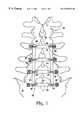
- FIG. 1 of the drawingsthere is shown a partially schematic, dorsal view of a portion of the human spinal column having a preferred embodiment of a spinal stabilizer constructed in accordance with the teachings of the present invention surgically affixed thereto.
- FIG. 2is a lateral view of the human spinal column having the spinal stabilizer of FIG. 1 affixed thereto and showing the spinal column in phantom lines to show the positions of the pedicle screws used to affix the spinal stabilizer to the spinal column.
- FIG. 3is a top plan view of a lumbar vertebra having the spinal stabilizer of FIGS. 1 and 2 affixed thereto and showing the vertebra in phantom lines to show the positions of the pedicle screws used to affix the spinal stabilizer to the spinal column.
- FIG. 4is top, perspective view of a preferred embodiment of a washer constructed in accordance with the teachings of the present invention.
- FIG. 5is a top, perspective view of a second preferred embodiment of a washer constructed in accordance with the teachings of the present invention.
- FIG. 6is a bottom, perspective view of a third preferred embodiment of a washer constructed in accordance with the teachings of the present invention.
- FIG. 7is a side elevational view of the washer of FIG. 6 .
- FIG. 8is a bottom, perspective view of a fourth preferred embodiment of a washer constructed in accordance with the teachings of the present invention.
- FIG. 9is a side elevational view of the washer of FIG. 8 .
- FIG. 10is a perspective view of a second embodiment of the washer of FIG. 8 .
- FIG. 11is a side elevational view of the washer of FIG. 10 .
- FIG. 12is a partially exploded, perspective view of a portion of the spinal stabilizer of FIGS. 1 and 2.
- FIG. 13is a side elevational view of a portion of the cross-bar of FIG. 12 .
- FIG. 14is a partially schematic, dorsal view of a portion of the human spinal column having another alternative embodiment of a spinal stabilizer constructed in accordance with the teachings of the present invention surgically affixed thereto.
- FIG. 15is a perspective view of the cross-bar of the spinal stabilizer of FIG. 14 .
- FIG. 16is a dorsal view of a single lumbar vertebrae having an alternative embodiment of a cross-bar constructed in accordance with the teachings of the present invention affixed thereto for use in connection with the spinal stabilizer of FIG. 14 .
- FIG. 17is an enlarged, top plan view of the cross-bar of FIG. 16 .
- FIG. 18is a detailed, side elevational view of a portion of the cross-bar of FIG. 16 .
- FIGS. 1 and 2A presently preferred embodiment of the spinal stabilizer of the present invention is shown affixed to the spinal column in FIGS. 1 and 2.
- the preferred embodiment, indicated generally at reference numeral 20is comprised of two rods 22 oriented along the longitudinal axis of the spinal column 24 on either side of the spinous processes 26 of lumbar vertebrae L 3 -L 5 and the first sacral vertebrae S 1 .
- Rods 22are connected at the level of each vertebrae S 1 , L 3 -L 5 by nut and screw 28 and 30 to cross-bar, or plate, 32 .
- the screws 30are preferably of a type known in the art in which the portion of the screw threads projecting through nut 28 is broken off so as not to project any further from the nut 28 than needed.
- Each cross-bar/plate 32is affixed to the corresponding vertebrae by a pedicle screw 34 , washer 36 , and nut 38 , screws 34 being anchored in the pedicle 40 (see FIG. 3) of each vertebrae.
- Screws 34shown in more detail in FIG. 12, are also of a type known in the art in which the bottom portion 33 is provided with threads for anchoring into the vertebrae, a head 35 with a rounded, or hemispherical upper surface 37 , and an upper threaded portion 39 for threadably receiving the nut 38 and the portion of the threads projecting through nut 38 is broken off so as not to project any further through nut 38 than needed.
- a screw of this typeis shown, for instance, in U.S. Pat. No. 5,129,899, which patent is incorporated herein in its entirety by this specific reference thereto.
- each screw 34is angled in three axes of a three-dimensional coordinate system (not shown) having its origin on the center axis of the spinal column 24 .
- the Y coordinate of the coordinate systemis coincident with the center of the longitudinal axis of the spinal column 24 (such that+Y is anterior and ⁇ Y is posterior), the X coordinate is the lateral dimension, and the Z coordinate is orthogonal to the plane of the paper in FIG. 1 (such that+Z is ventral and ⁇ Z is dorsal), it can be seen in FIG. 2 that the positions of the tips of the screws 34 are defined by Y and Z coordinates.
- Reference to FIG. 3(in which the Y coordinate of the hypothetical coordinate system runs in and out of the plane of the paper) illustrates that the positions of the tips of the same screws are also defined by an X coordinate.
- the ends 44 of cross-bar 32are angled downwardly, or ventrally (relative to the body of the patient), to accommodate the round shape of the body 42 of the vertebrae L 4 to which the cross-bar 32 is affixed by screws 34 .
- this bend at the ends 44 of cross-bar 32serves several advantages other than accommodating the shape of the vertebral body (for instance, reducing the height of the stabilizer in the direction of the Z coordinate of the three-dimensional coordinate system described above) and therefore represents a preferred embodiment of the spinal fixation system of the present invention.
- the downward bends at the ends 44also introduces yet another angle into the interface between the screw 34 and the cross-bar 32 .
- FIGS. 4-9show a plurality of washers 36 constructed in accordance with the teachings of the present invention shaped and/or configured to provide optimal load transfer from the spinal column 24 to the spinal stabilizer 20 .
- the washers 36 c and 36 o shown in FIGS. 4 and 5, respectively,are comprised of a cylindrical body 46 having a longitudinal passage 48 therethrough for receiving the screw 34 for affixing the spinal stabilizer 20 to the vertebral body 42 .
- the passage 48 through the body 46 of washer 36 cis centered on the longitudinal axis (represented by the phantom line in FIG. 4) of washer 36 c and the passage 48 in the body 46 of washer 36 o (FIG.
- each of the washers 36 c and 36 ois also provided with means formed on the body 46 for rotatably engaging the spinal stabilizer 20 .
- the stabilizer engaging meanstakes the form of a shoulder 50 formed on the body 46 of the washers 36 c and 36 o which rests on the margins of the hole 52 formed in the ends 44 of cross-bar 32 when the washer 36 c or 36 o is assembled to the cross-bar 32 in the manner described below.
- the stabilizer engaging meansneed not be comprised of the shoulder 50 .
- the stabilizer engaging meanstakes the form of three or more projections on the surface of the walls of the cylindrical body (the “O.D.” of the body) which, when the body is inserted through the hole 52 in the cross-bar 32 . create an interference with the margin of hole 52 so that the washer effectively sits in the hole 52 with the projections on the O.D. of the body acting as a spider to support the washer in the hole 52 .
- the stabilizer engaging meanstakes the form of a plurality of projections projecting radially inwardly from the margins of the hole in the cross-bar for engaging a shoulder or slot formed on the O.D. of the body of the washer.
- the washersare comprised of a resilient material such as a medical grade polymeric material which are provided with a groove formed on the O.D. thereof which is press-fit into the hole 52 in cross-bar 32 .
- FIGS. 6-7 and 8 - 9Other preferred embodiments of the washer 36 of the present invention are shown in FIGS. 6-7 and 8 - 9 .
- the hole 48 in the cylindrical body 46 of washer 36 c shown in FIGS. 6 and 7is centered on the longitudinal axis (represented by the phantom line in FIG. 6) of washer 36 c and, when viewed from the end 49 , the longitudinal passage 48 in the cylindrical body 46 of washer 36 o in FIGS. 8 and 9 is offset from the center of the longitudinal axis (represented by the phantom line in FIG. 8) of washer 36 o .
- the washers 36 shown in FIGS. 6-9are provided with means for rotatably engaging the spinal stabilizer 20 .
- the stabilizer engaging meanstakes the form of a shoulder 50 formed on the body 46 of washers 36 c and 36 o which rests on the margins of the hole 52 formed in the ends 44 of cross-bar 32 when the washer 36 c or 36 o is assembled to the cross-bar 32 (the manner in which the shoulder functions is described below).
- shoulder engaging meanssuch as are described above may be provided on the washers 36 to accomplish the intended function of allowing the washer 36 to rotate in engagement with cross-bar 32 .
- the bodies 46 of the washers 36are described as being cylindrical to provide a basis for referring to the longitudinal axis of the washer 36 even though it will be recognized that the height of the right angle cylinder defined by the washers of FIGS. 4 and 5 is minimal since the washers shown in FIGS. 4 and 5 are accurately described as “flat washers.”
- one end 49 of the bodies 46 of the washers 36 shown in FIGS. 6-9is angled relative to the side walls of the cylindrically-shaped body 46 of washer 36 .
- the end 49is angled at an angle of approximately 90° such that the washers shown in those figures are flat, but the end 49 of the bodies 46 of the washers 36 shown in FIGS. 6-9 is angled relative to the side walls at an angle other than 90° such that the bodies 46 of washers 36 shown in those figures have a substantial vertical dimension and are wedge-shaped rather than flat.
- FIGS. 10 and 11an alternative embodiment of the washer of the present invention is shown.
- the washer 36 shown in FIGS. 11 and 12is similar to the washers shown in FIGS. 6-9, but is provided with a concave upper surface 49 for interaction with a nut 38 (not shown) having a convex lower surface.
- the concave upper surface 49provides an even greater range of angles and adjustability of placement of the screw 34 relative to the central axis of the spinal column.
- washers 36rotatably engage cross-bar 32 at the ends 44 .
- rotatable engagementis accomplished by resting the shoulders 50 of washers 36 comprising the preferred stabilizer engaging means on the margins of the holes 52 at the ends of cross-bars 32 .
- the surgeonselects either
- the washer selectedis preferably the washer which, by its shape and ability to be rotated, locates the passage therethrough in the proper position for receiving the screw 34 while maintaining an angle of approximately 90° between the longitudinal axis of the screw 34 and the surface 49 of the washer against which the nut 38 bears when tightened to effectively transfer load from the spinal column 24 to the implant 20 .
- one end 44 of cross-bar 32may be provided with a gap or break 45 through which the portion of the screw 34 protruding from the pedicle is maneuvered. Also, because the angle between the underside of cross-bar 32 and the longitudinal axis of screw 34 is unlikely to be a 90° angle and/or the screw 34 may be positioned close to the inside margin of the hole 52 in cross-bar 32 , the upper surface 37 of the head 35 of screw 34 is rounded and the inside surface of the margin of the holes 52 in cross-bar 32 is beveled as shown at reference numeral 53 in FIG. 13 .
- the head of screw 34is sized so as to contact the margin of hole 52 in cross-bar 32 , the bevel 53 and complementary rounded upper surface 37 of the screw 34 helping to center the longitudinal axis of hole 52 in cross-bar 32 on the longitudinal axis of screw 34 .
- FIG. 12shows the interaction and adjustability of the spinal implant of the present invention by showing one screw 34 to which a nut 38 is tightened against the wedge-shaped washer 36 o of FIGS. 8 and 9 with the washer 360 having been rotated relative to cross-bar 32 so that the screw 34 is angled anteriorally (with reference to the patient) while also being angled inwardly (relative to the central axis of the spinal column 24 ).
- a flat washer 36 ois shown on the other side of the cross-bar 32 which has been rotated so that the screw 34 is not centered in the hole 52 of cross-bar 32 but the inward angle of the screw resulting from the downward bend at the ends 44 of cross-bar 32 is maintained.
- Cross-bar 32is shown with an optional nipple 56 forming a stop surface 58 near the holes 52 therethrough which acts, by engagement of the O.D. of the washer 36 , to restrain any tendency of the washer 36 to move inwardly from the ends 44 of cross-bar while the nut 38 is being tightened against the washer 36 when in place in the hole 52 in cross-bar 32 .
- the portion of cross-bar 32 intermediate the ends 44is provided with a plurality of nested slots 60 of a type known in the art (see, for instance, U.S. Pat. No. 4,696,290 and the so-called VSP spinal fixation system described in J. W. Brantigan, et al., Posterior lumbar interbody fusion technique using the variable screw placement spinal fixation system, in D. M. Arnold and J. E.
- the attachment between rods 22 and cross-bars 32is accomplished by tightening nuts 28 to the posts 62 integrally mounted to the plate 64 which moves from side to side along the longitudinal axis of cross-bar 32 in the slot 66 formed therein.
- the plate 64is comprised of a flat portion (not visible in FIG. 12 because of the perspective in the figure) which extends under the cross-bar and which is tightened against the underside of cross-bar 32 when the nut 28 is tightened against a rod 22 to prevent further side to side movement of the plate 64 and post 62 .
- the plateis moved by the surgeon to the position which allows precise alignment of the rod 22 with the cross-bar 32 .
- the plate 64is provided with a portion extending under cross-bar 32 which is tightened against the underside of cross-bar 32 when the nut 28 is tightened on connector 68 to resist further side to side movement.
- connectors 68are provided with a head for engaging the underside of the cross-bar 32 in the same manner as the screws 30 .
- FIGS. 16-18there is shown a cross-bar 72 of a type modified for use in connection with the embodiment of the spinal stabilizer of the present invention shown in FIGS. 14-15.
- the cross-bar 72is provided with hooks 74 for engaging the lamina of the vertebra and a retainer 76 which is curved so as to extend under the lamina to which cross-bar 72 is to be affixed.
- the hooks 74extend through a slot (not numbered for the sake of clarity) formed at approximately a right angle to the longitudinal axis of cross-bar 72 and are extended in and out of that slot until they are adjusted so as to tightly engage the posterior margin of the lamina and then set in that position by tightening the set screw 78 provided in cross-bar 72 for that purpose.
- U-shaped connectors 68 mounted on plates 64 as described aboveare provided for connecting to a rod 22 as shown in FIGS. 14-15.
- the present inventionis equally adaptable to a spinal fixation system which is comprised of rods on either side of the processes of the vertebrae which may or may not be connected by a cross-bar or a system comprised of a single rod down the dorsal aspect of the spinal column after removal of the dorsal processes rather than the ladder-type system shown in the figures. All such changes, and the others known to those skilled in the art, are intended to fall within the scope of the following non-limiting claims.
Landscapes
- Health & Medical Sciences (AREA)
- Orthopedic Medicine & Surgery (AREA)
- Life Sciences & Earth Sciences (AREA)
- Neurology (AREA)
- Surgery (AREA)
- Molecular Biology (AREA)
- Veterinary Medicine (AREA)
- Biomedical Technology (AREA)
- Heart & Thoracic Surgery (AREA)
- Medical Informatics (AREA)
- Nuclear Medicine, Radiotherapy & Molecular Imaging (AREA)
- Animal Behavior & Ethology (AREA)
- General Health & Medical Sciences (AREA)
- Public Health (AREA)
- Engineering & Computer Science (AREA)
- Surgical Instruments (AREA)
- Prostheses (AREA)
- Joining Of Building Structures In Genera (AREA)
- Joints Allowing Movement (AREA)
- Mutual Connection Of Rods And Tubes (AREA)
- Earth Drilling (AREA)
- Non-Disconnectible Joints And Screw-Threaded Joints (AREA)
Abstract
Description
The present invention relates to multi-axis internal spinal fixation. In more detail, the present invention relates to an internal spinal fixation system, and a method of stabilizing, or fixing, the spine for use with either bilateral rods or plates such as the Steffee/variable screw placement system or a central rod and plurality of cross-bars or plates such as the so-called Tacoma Monorail System, utilizing wedge-shaped and/or flat washers having off-set and/or centered openings therein to provide multiple axes for the pedicle screws used to fix the rods, cross-bars, and/or plates to the vertebrae of the patient.
There are many systems available for internal fixation of the spine. Such systems are described in the patent literature (see, for instance, U.S. Pat. Nos. 4,696,290, 5,092,866, and 5,129,899) and the scientific literature (see, for instance, D. M. Arnold and J. E. Lonstein (Eds.), 6 State of the Art Reviews—Spine: Pedicle Fixation of the Lumbar Spine (Philadelphia: Nanley & Belfus, Inc.) 1992 and H. S. An and J. M. Cotler (Eds.), Spinal Instrumentation (Baltimore: Williams & Wilkins) 1992), and are available from such vendors as AcroMed, Smith & Nephew, MOSS® Miami, Osteonics, Sofamor Danek, and others.
A problem with all such systems, however, is the joint between the screws used to affix the system to the pedicle and the rods, cross-bars, and/or plates of the system. As stated in J. M. Cotler, et al., Principles, Indications, and Complications of Spinal Instrumentation: A Summary Chapter, in H. S. An and J. M. Cotler, Spinal Instrumentation pp. 435-456 (Baltimore: Williams & Wilkins) 1992, “[a] significant problem in pedicular screw fixation appears to be at the site of linkage between the screw and rod or plate.”
It appears that the problems at the site of this linkage may result from the geometry of the joint between the screw and the rod or plate. This difficult geometry results from several factors, including the different angles and placement of the vertebrae and their relative sizes, the shape of the vertebrae and the spacing between vertebrae, the placement of the screws, the lordosis of the spine, and the need to insert the screws into each vertebra at an angle. With regard to the angle of the pedicle screws, pedicle screws are angled inwardly and upwardly into the vertebra for maximum strength and, because the surfaces of the pedicles of each vertebrae are angled relative to each other, the screws rarely line up across the vertebral body into which they are screwed. Nor do they line up from one vertebra to the adjacent vertebra even if the adjacent vertebrae are the same size and shape (which they generally are not). For a more complete discussion of the biomechanics of the bone-implant interface, reference is made to H. A. Pool and R. W. Gaines, Biomechanics of Transpedicular Screw Spinal Implant Systems, in D. M. Arnold and J. E. Lonstein (Eds.), 6 State of the Art Reviews—Spine: Pedicle Fixation of the Lumbar Spine 37-44 (Philadelphia: Nanley & Belfus, Inc.) 1992, M. R. Pinto, Complication of Pedicle Screw Fixation, in D. M. Arnold and J. E. Lonstein (Eds.), 6 State of the Art Reviews—Spine: Pedicle Fixation of the Lumbar Spine 45-54 (Philadelphia: Nanley & Belfus, Inc.) 1992, and M. H. Krag, Vermont Spinal Fixator, in D. M. Arnold and J. E. Lonstein (Eds.), 6 State of the Art Reviews—Spine: Pedicle Fixation of the Lumbar Spine 121-145 (Philadelphia: Nanley & Belfus, Inc.) 1992, which references are incorporated herein in their entirety by these specific references thereto. Because the pedicle screws do not line up, the rod which runs along the longitudinal axis of the patient's spinal column, which provides the structural rigidity required to stabilize the spine, must either be bent to the location of each screw head or the stabilizer must be provided with adjustable structure which enables the screw head to be attached to the rod.
As a result of this difficulty, the literature includes comments such as the following statement in R. M. Puno and J. A. Byrd III, Transpedicular Screw/Rod Fixation Using the Puno-Winter-Byrd(PWB) System, in D. M. Arnold and J. E. Lonstein (Eds.), 6 State of the Art Reviews—Spine: Pedicle Fixation of the Lumbar Spine 83-106 (Philadelphia: Nanley & Belfus, Inc.) 1992:
“Transpedicular fixation has been proved to be of value in the treatment of spinal disorders . . . However, experience has shown that this method of instrumentation places great demand on the surgeon's skill because of the anatomic constraints related mainly to the anatomy and morphometry of the spinal pedicle.”
Many of the above-listed systems, and many of the systems described in the literature, attempt to relieve this burden on the surgeon by providing angled screws (for instance, the AMSET® R-F reduction-fixation system), so-called polyaxial screws (for example, the MOSS® Miami system noted above), full-length, scalloped, open-slot plate design with an undersurface complementary to the shape of the screw head (the Sofamor Danek plate and screw system noted above for example) for optimal positioning of the screws and up to 15° medial-lateral and 30° craniocaudal angulation at the screw-plate interface, and infinitely variable couplers (the so-called Rogozinski spinal rod system for example) which are said to allow rotation through a 130° arc to allow screw placement within the pedicle with no requirement to align each screw with the screw in the adjacent vertebrae.
Although these prior systems address these problems, as evidenced by the fact that new systems are introduced by the same vendors which are already marketing the above-listed systems, no currently available system completely solves all the problems presented by the need for optimal screw placement, angulation of the screw, and effective load transfer from spinal column to implant. An ideal system would (a) accomodate optimal screw placement, height, and angulation, (b) accomodate different sizes and shapes of vertebrae, (c) minimize (or not require) bending or other fabrication during surgery, (d) maintain an angle of approximately 90° between the screw head and the plate or cross-bar to which the screw is attached for effective load transfer from spinal column to implant and to minimize the likelihood of slippage and/or gross failure, and (e) be strong enough to provide lasting and rigid fixation of the spine. Those skilled in the art will recognize that this list is not exhaustive, but is instead intended to illustrate some of the desirable characteristics of an ideal internal fixation system. Other design criteria are also important, and some practicioners may consider some criteria so important that they might not even list others.
So far as is known, none of the above-listed internal fixation systems meets these criteria in every patient. The disadvantages and limitations of currently available systems are made clear from reports in the literature of failure rates (failure of the device, not such complications as infection, phlebitis, seroma, neurologic deficit, etc.) as high as 25% (see R. Roy-Camille, et al., 203 Clin. Orthop. 7 (1986)), 11% (see, S. F. Heim and E. R. Luque, Danek Plate and Screw System, in D. M. Arnold and J. E. Lonstein (Eds.), 6 State of the Art Reviews—Spine: Pedicle Fixation of the Lumbar Spine 201-234 (Philadelphia: Nanley & Belfus, Inc.) 1992), 8% (see, R. M. Puno and J. A. Byrd III, Transpedicular Screw/Rod Fixation Using the Puno/Winter/Byrd (PWB) System, supra), and 2-7% D. M. Arnold and L. L. Wiltse, The Wiltse System of Internal Fixation for the Lumbar Spine, in D. M. Arnold and J. E. Lonstein (Eds.), 6 State of the Art Reviews—Spine: Pedicle Fixation of the Lumbar Spine 55-82 (Philadelphia: Nanley & Belfus, Inc.) 1992.
The currently available systems have other limitations. By way of example, so far as is known, no currently available surgically implanted system can predictably treat rotoscoliosis. Further, no currently available system is conveniently used in multiple level surgery. Multiple level surgery is a challenge for the surgeon because of the need to align the pedicle screws in multiple vertebrae while working under the heavy muscles of the back.
There is therefore a need for improvement of such systems, and it is this improvement to which the present invention is directed. In particular, it is an object of the present invention to improve the screw-plate interface in those systems in which the screw is angled and/or spaced at varying intervals. Another object of the present invention is to provide flexibility of placement, angulation, spacing, and screw height for accomodating the pedicle screws of such systems. Another object of the present invention is to provide a system which is universal in the sense that, although comprised of relatively few parts, it will work with pedicle screws and laminar hooks, thereby providing even more flexibility and ease of use. Another object of the present invention is to provide an internal spinal fixation system which avoids surgery under the heavy muscles of the back so that the surgery is simplified and there is more room for fusion of adjacent vertebrae in the lateral gutter. Other objects, and the advantages, of the present invention will be made clear to those skilled in the art by the following description of the preferred embodiments thereof.
These objects, and other objects to be made clear by the following detailed description of the preferred embodiments of the invention, are met by providing a spinal stabilizer comprising a rod, a screw, a cross-bar having a hole therein, means for attaching the cross-bar to the rod, and a washer. The washer comprises a cylindrical body having one end angled with respect to the side walls of the cylindrical body and a longitudinal passage therethrough for receiving the screw for affixing the cross-bar to the vertebra of a patient. The washer also comprises means for resting on and rotatably engaging the margins of the hole in the cross-bar so that the body is capable of being rotated in the hole in the cross-bar to provide an infinite variety of angles and pedicle screw placements while maintaining an optimal interface between the head of the screw and the washer so as to effectively transfer the load from the spinal column to the cross-bar.
In another aspect, the present invention contemplates a novel washer for use in connection with an internal spinal stabilizer which comprises a wedge-shaped, cylindrical body with a hole through the body which is offset from the center of the longitudinal axis of the washer. The hole receives a screw for affixing an internal spinal stabilizer to the vertebral body of a patient. Means is formed on said body for rotatably engaging the spinal stabilizer to allow the body to rotate around the 360° of the hole to provide infinite variability in the angle and location of the interface between the screw and the plate.
The present invention also provides a method of affixing a spinal stabilizer to the vertebra of a patient, the stabilizer comprising a washer having an off-center passage therethrough, a cross-bar, and a screw, comprising the steps of engaging the cross-bar with the washer, driving the screw into the vertebral body through the passage in the washer, and changing the angle of the screw relative to the vertebral body to which the cross-bar is affixed by rotating the washer relative to the cross-bar.
In a second embodiment of the method of affixing a spinal stabilizer to the vertebra of a patient, the spinal stabilizer comprises a washer having a cylindrical body with one end angled with respect to the side walls of the cylinder and a longitudinal passage therethrough, a cross-bar, and a screw, and the method comprises the steps of engaging the cross-bar with the washer, driving the screw into the vertebral body through the passage in the washer, and changing the angle of the screw relative to the vertebral body to which the cross-bar is affixed by rotating the washer relative to the cross-bar.
Referring now to the FIG. 1 of the drawings, there is shown a partially schematic, dorsal view of a portion of the human spinal column having a preferred embodiment of a spinal stabilizer constructed in accordance with the teachings of the present invention surgically affixed thereto.
FIG. 2 is a lateral view of the human spinal column having the spinal stabilizer of FIG. 1 affixed thereto and showing the spinal column in phantom lines to show the positions of the pedicle screws used to affix the spinal stabilizer to the spinal column.
FIG. 3 is a top plan view of a lumbar vertebra having the spinal stabilizer of FIGS. 1 and 2 affixed thereto and showing the vertebra in phantom lines to show the positions of the pedicle screws used to affix the spinal stabilizer to the spinal column.
FIG. 4 is top, perspective view of a preferred embodiment of a washer constructed in accordance with the teachings of the present invention.
FIG. 5 is a top, perspective view of a second preferred embodiment of a washer constructed in accordance with the teachings of the present invention.
FIG. 6 is a bottom, perspective view of a third preferred embodiment of a washer constructed in accordance with the teachings of the present invention.
FIG. 7 is a side elevational view of the washer of FIG.6.
FIG. 8 is a bottom, perspective view of a fourth preferred embodiment of a washer constructed in accordance with the teachings of the present invention.
FIG. 9 is a side elevational view of the washer of FIG.8.
FIG. 10 is a perspective view of a second embodiment of the washer of FIG.8.
FIG. 11 is a side elevational view of the washer of FIG.10.
FIG. 12 is a partially exploded, perspective view of a portion of the spinal stabilizer of FIGS. 1 and 2.
FIG. 13 is a side elevational view of a portion of the cross-bar of FIG.12.
FIG. 14 is a partially schematic, dorsal view of a portion of the human spinal column having another alternative embodiment of a spinal stabilizer constructed in accordance with the teachings of the present invention surgically affixed thereto.
FIG. 15 is a perspective view of the cross-bar of the spinal stabilizer of FIG.14.
FIG. 16 is a dorsal view of a single lumbar vertebrae having an alternative embodiment of a cross-bar constructed in accordance with the teachings of the present invention affixed thereto for use in connection with the spinal stabilizer of FIG.14.
FIG. 17 is an enlarged, top plan view of the cross-bar of FIG.16.
FIG. 18 is a detailed, side elevational view of a portion of the cross-bar of FIG.16.
A presently preferred embodiment of the spinal stabilizer of the present invention is shown affixed to the spinal column in FIGS. 1 and 2. The preferred embodiment, indicated generally atreference numeral 20, is comprised of tworods 22 oriented along the longitudinal axis of thespinal column 24 on either side of the spinous processes26 of lumbar vertebrae L3-L5 and the first sacral vertebrae S1.Rods 22 are connected at the level of each vertebrae S1, L3-L5 by nut and screw28 and30 to cross-bar, or plate,32. Thescrews 30 are preferably of a type known in the art in which the portion of the screw threads projecting throughnut 28 is broken off so as not to project any further from thenut 28 than needed. Each cross-bar/plate 32 is affixed to the corresponding vertebrae by apedicle screw 34,washer 36, andnut 38, screws34 being anchored in the pedicle40 (see FIG. 3) of each vertebrae.Screws 34, shown in more detail in FIG. 12, are also of a type known in the art in which thebottom portion 33 is provided with threads for anchoring into the vertebrae, ahead 35 with a rounded, or hemisphericalupper surface 37, and an upper threadedportion 39 for threadably receiving thenut 38 and the portion of the threads projecting throughnut 38 is broken off so as not to project any further throughnut 38 than needed. A screw of this type is shown, for instance, in U.S. Pat. No. 5,129,899, which patent is incorporated herein in its entirety by this specific reference thereto.
As noted above, the need for secure anchorage of thescrews 34 in the vertebrae, the lordosis of the spine and corresponding curve in rods22 (best shown in FIG.2), inward angle of the screws34 (best shown in FIG.3), different sizes, spacing, and shapes of thevertebral bodies 42, and many other factors (including the particular pathology which the spinal fixation system is intended to address), require that almost everyscrew 34 must be oriented at a unique angle relative torods 22. To illustrate, in FIGS. 1-3, it can be seen that each screw is angled in three axes of a three-dimensional coordinate system (not shown) having its origin on the center axis of thespinal column 24. If the Y coordinate of the coordinate system is coincident with the center of the longitudinal axis of the spinal column24 (such that+Y is anterior and−Y is posterior), the X coordinate is the lateral dimension, and the Z coordinate is orthogonal to the plane of the paper in FIG. 1 (such that+Z is ventral and−Z is dorsal), it can be seen in FIG. 2 that the positions of the tips of thescrews 34 are defined by Y and Z coordinates. Reference to FIG. 3 (in which the Y coordinate of the hypothetical coordinate system runs in and out of the plane of the paper) illustrates that the positions of the tips of the same screws are also defined by an X coordinate.
Referring now to FIG. 3, it can be seen that the ends44 of cross-bar32 are angled downwardly, or ventrally (relative to the body of the patient), to accommodate the round shape of thebody 42 of the vertebrae L4 to which the cross-bar32 is affixed byscrews 34. Although the cross-bar32 need not be shaped in this fashion, this bend at theends 44 of cross-bar32 serves several advantages other than accommodating the shape of the vertebral body (for instance, reducing the height of the stabilizer in the direction of the Z coordinate of the three-dimensional coordinate system described above) and therefore represents a preferred embodiment of the spinal fixation system of the present invention. However, the downward bends at theends 44 also introduces yet another angle into the interface between thescrew 34 and the cross-bar32. As a result of the angle of thescrew 34 and the bend at theend 44 of cross-bar32, the longitudinal axis ofscrew 34 is unlikely to be perpendicular to cross-bar32 at the interface between thescrew 34 and cross-bar32, and therefore unlikely to optimally transfer load from thespinal column 24 to thespinal stabilizer 20.
FIGS. 4-9 show a plurality ofwashers 36 constructed in accordance with the teachings of the present invention shaped and/or configured to provide optimal load transfer from thespinal column 24 to thespinal stabilizer 20. Thewashers cylindrical body 46 having alongitudinal passage 48 therethrough for receiving thescrew 34 for affixing thespinal stabilizer 20 to thevertebral body 42. Thepassage 48 through thebody 46 ofwasher 36cis centered on the longitudinal axis (represented by the phantom line in FIG. 4) ofwasher 36cand thepassage 48 in thebody 46 of washer36o(FIG. 5) is offset from the center of the longitudinal axis of thewasher 36ofor a purpose to be described below. Each of thewashers body 46 for rotatably engaging thespinal stabilizer 20. In the preferred embodiment shown, the stabilizer engaging means takes the form of ashoulder 50 formed on thebody 46 of thewashers hole 52 formed in theends 44 of cross-bar32 when thewasher
Those skilled in the art will recognize that the stabilizer engaging means need not be comprised of theshoulder 50. In an alternative embodiment, the stabilizer engaging means takes the form of three or more projections on the surface of the walls of the cylindrical body (the “O.D.” of the body) which, when the body is inserted through thehole 52 in the cross-bar32. create an interference with the margin ofhole 52 so that the washer effectively sits in thehole 52 with the projections on the O.D. of the body acting as a spider to support the washer in thehole 52. Alternatively, and particularly in the case of the washers shown in FIGS. 6-10 described below, the O.D. of thebody 46 ofwasher 36 is provided with a groove and the washer is inserted with the angled top surface49 (see below) up from beneath thehole 52 in cross-bar32 and rotated so that the groove engages and interacts with the margin of thehole 52 so as to limit the travel of the washer through thehole 52. In another embodiment, the stabilizer engaging means takes the form of a plurality of projections projecting radially inwardly from the margins of the hole in the cross-bar for engaging a shoulder or slot formed on the O.D. of the body of the washer. In yet another embodiment, the washers are comprised of a resilient material such as a medical grade polymeric material which are provided with a groove formed on the O.D. thereof which is press-fit into thehole 52 in cross-bar32. All such embodiments, and others functioning to allow the washer to rotatably engage the cross-bar which may be developed by those skilled in the art who have the benefit of this disclosure, are considered equivalent to the structure disclosed herein and are therefore considered to be constructed in accordance with the present invention.
Other preferred embodiments of thewasher 36 of the present invention are shown in FIGS. 6-7 and8-9. Again, thehole 48 in thecylindrical body 46 ofwasher 36cshown in FIGS. 6 and 7 is centered on the longitudinal axis (represented by the phantom line in FIG. 6) ofwasher 36cand, when viewed from theend 49, thelongitudinal passage 48 in thecylindrical body 46 ofwasher 36oin FIGS. 8 and 9 is offset from the center of the longitudinal axis (represented by the phantom line in FIG. 8) ofwasher 36o. Unlike thewashers 36 shown in FIGS. 4 and 5, theend 49 of each of the washers shown in FIGS. 6-9 is angled at an angle other than 90° relative to the side walls of the cylindrically-shapedbody 46, giving the body46 a wedge shape. As a result of theangled end 49 ofbody 46, the central axis of thehole 48 throughwasher 36oshown in FIGS. 8-9 is not parallel to the longitudinal axis of thebody 46.
Like thewashers 36 shown in FIGS. 4-5, thewashers 36 shown in FIGS. 6-9 are provided with means for rotatably engaging thespinal stabilizer 20. As described above, in the preferred embodiment, the stabilizer engaging means takes the form of ashoulder 50 formed on thebody 46 ofwashers hole 52 formed in theends 44 of cross-bar32 when thewasher washers 36 to accomplish the intended function of allowing thewasher 36 to rotate in engagement with cross-bar32.
Thebodies 46 of thewashers 36 are described as being cylindrical to provide a basis for referring to the longitudinal axis of thewasher 36 even though it will be recognized that the height of the right angle cylinder defined by the washers of FIGS. 4 and 5 is minimal since the washers shown in FIGS. 4 and 5 are accurately described as “flat washers.” However, as set out above, oneend 49 of thebodies 46 of thewashers 36 shown in FIGS. 6-9 is angled relative to the side walls of the cylindrically-shapedbody 46 ofwasher 36. In the embodiments shown in FIGS. 4 and 5, theend 49 is angled at an angle of approximately 90° such that the washers shown in those figures are flat, but theend 49 of thebodies 46 of thewashers 36 shown in FIGS. 6-9 is angled relative to the side walls at an angle other than 90° such that thebodies 46 ofwashers 36 shown in those figures have a substantial vertical dimension and are wedge-shaped rather than flat.
Referring now to FIGS. 10 and 11, an alternative embodiment of the washer of the present invention is shown. Thewasher 36 shown in FIGS. 11 and 12 is similar to the washers shown in FIGS. 6-9, but is provided with a concaveupper surface 49 for interaction with a nut38 (not shown) having a convex lower surface. When tightened onto thepedicle screw 34. the concaveupper surface 49 provides an even greater range of angles and adjustability of placement of thescrew 34 relative to the central axis of the spinal column.
As best shown in FIGS. 3 and 12,washers 36 rotatably engage cross-bar32 at the ends44. As described above, rotatable engagement is accomplished by resting theshoulders 50 ofwashers 36 comprising the preferred stabilizer engaging means on the margins of theholes 52 at the ends ofcross-bars 32. During the surgical procedure, the surgeon selects either
a flat washer with a longitudinal passage coincident with the center of the longitudinal axis of the washer (FIG.4),
a flat washer with a passage offset from the center of the longitudinal axis of the washer (FIG.5),
a wedge-shaped washer with a passage coincident with the center of the longitudinal axis of the washer (FIGS.6-7), or
a wedge-shaped washer with a passage offset from the center of the longitudinal axis of the washer (FIGS.8-9),
and then rotates thebody 46 of thewasher 36 selected in thehole 52 to provide infinite adjustability of the linkage between the cross-bar32 andscrew 34, regardless of the angle and position of thescrews 34 in thepedicle 40 of each vertebrae and regardless of the shape, size, or pathology of the vertebrae and/or pedicle. The washer selected is preferably the washer which, by its shape and ability to be rotated, locates the passage therethrough in the proper position for receiving thescrew 34 while maintaining an angle of approximately 90° between the longitudinal axis of thescrew 34 and thesurface 49 of the washer against which thenut 38 bears when tightened to effectively transfer load from thespinal column 24 to theimplant 20.
To facilitate assembly of the cross-bar32 to thescrews 34, oneend 44 of cross-bar32 may be provided with a gap or break45 through which the portion of thescrew 34 protruding from the pedicle is maneuvered. Also, because the angle between the underside of cross-bar32 and the longitudinal axis ofscrew 34 is unlikely to be a 90° angle and/or thescrew 34 may be positioned close to the inside margin of thehole 52 in cross-bar32, theupper surface 37 of thehead 35 ofscrew 34 is rounded and the inside surface of the margin of theholes 52 in cross-bar32 is beveled as shown atreference numeral 53 in FIG.13. In another embodiment (not shown), the head ofscrew 34 is sized so as to contact the margin ofhole 52 in cross-bar32, thebevel 53 and complementary roundedupper surface 37 of thescrew 34 helping to center the longitudinal axis ofhole 52 in cross-bar32 on the longitudinal axis ofscrew 34.
FIG. 12 shows the interaction and adjustability of the spinal implant of the present invention by showing onescrew 34 to which anut 38 is tightened against the wedge-shapedwasher 36oof FIGS. 8 and 9 with thewasher 360 having been rotated relative to cross-bar32 so that thescrew 34 is angled anteriorally (with reference to the patient) while also being angled inwardly (relative to the central axis of the spinal column24). Aflat washer 36ois shown on the other side of the cross-bar32 which has been rotated so that thescrew 34 is not centered in thehole 52 of cross-bar32 but the inward angle of the screw resulting from the downward bend at theends 44 of cross-bar32 is maintained. Cross-bar32 is shown with anoptional nipple 56 forming astop surface 58 near theholes 52 therethrough which acts, by engagement of the O.D. of thewasher 36, to restrain any tendency of thewasher 36 to move inwardly from theends 44 of cross-bar while thenut 38 is being tightened against thewasher 36 when in place in thehole 52 in cross-bar32.
Referring briefly again to FIG. 1, the portion of cross-bar32 intermediate the ends44 is provided with a plurality of nestedslots 60 of a type known in the art (see, for instance, U.S. Pat. No. 4,696,290 and the so-called VSP spinal fixation system described in J. W. Brantigan, et al., Posterior lumbar interbody fusion technique using the variable screw placement spinal fixation system, in D. M. Arnold and J. E. Lonstein (Eds.), 6 State of the Art Reviews—Spine: Pedicle Fixation of the Lumbar Spine 201-234 (Philadelphia: Nanley & Belfus, Inc.) 1992, both references being hereby incorporated in their entirety by this specific reference thereto) for precise placement of thescrews 30 securing therods 22 to the cross-bars32 along the longitudinal axis of cross-bar32. Thescrews 30 for securing therods 22 to the cross-bars32 are of the above-described type known in the art in which the portion of the screw which extends above the top surface of thenut 28 is broken off after the nut is tightened.
By comparison to FIG. 1, it can be seen that in the embodiment shown in FIG. 12, the attachment betweenrods 22 andcross-bars 32 is accomplished by tighteningnuts 28 to theposts 62 integrally mounted to theplate 64 which moves from side to side along the longitudinal axis of cross-bar32 in theslot 66 formed therein. Theplate 64 is comprised of a flat portion (not visible in FIG. 12 because of the perspective in the figure) which extends under the cross-bar and which is tightened against the underside of cross-bar32 when thenut 28 is tightened against arod 22 to prevent further side to side movement of theplate 64 andpost 62. Before tightening thenut 28, the plate is moved by the surgeon to the position which allows precise alignment of therod 22 with the cross-bar32.
In the alternative embodiment shown in FIGS. 14-15, therods 22 are of a type known in the art such as those available from MOSS® Miami (Cat. No. 1745-70, -72, and -74) which are attached to cross-bars32 byU-shaped connectors 68 havingthreads 70 formed on the outside surfaces thereof.Connectors 68 are integrally mounted to aplate 64 having a construction similar to that of the so-called axial connectors available from MOSS® Miami (Cat. No. 1745-61 and -62), e.g., two halves (not shown) with threaded posts and nuts for connecting the halves on the top and bottom of the cross-bar32 to clamp the cross-bar32 and prevent side to side movement of theplate 64 in theslot 66 in cross-bar32 in which theplate 64 moves. Alternatively, theplate 64 is provided with a portion extending under cross-bar32 which is tightened against the underside of cross-bar32 when thenut 28 is tightened onconnector 68 to resist further side to side movement. Those skilled in the art will recognize from this description of theconnectors 68 andplates 64 that a similar arrangement may be used in place of the nestedslots 60 in the cross-bar32 of the embodiment shown in FIG. 1 wherein the threadedposts 62 are replaced byconnectors 68 for precise lateral placement of the point at which therods 22 are attached to cross-bars32. In such an embodiment,connectors 68 are provided with a head for engaging the underside of the cross-bar32 in the same manner as thescrews 30.
Referring now to FIGS. 16-18, there is shown a cross-bar72 of a type modified for use in connection with the embodiment of the spinal stabilizer of the present invention shown in FIGS. 14-15. The cross-bar72 is provided withhooks 74 for engaging the lamina of the vertebra and aretainer 76 which is curved so as to extend under the lamina to which cross-bar72 is to be affixed. Thehooks 74 extend through a slot (not numbered for the sake of clarity) formed at approximately a right angle to the longitudinal axis of cross-bar72 and are extended in and out of that slot until they are adjusted so as to tightly engage the posterior margin of the lamina and then set in that position by tightening the set screw78 provided in cross-bar72 for that purpose.U-shaped connectors 68 mounted onplates 64 as described above are provided for connecting to arod 22 as shown in FIGS. 14-15.
Although described in terms of the presently preferred embodiment shown in the figures, those skilled in the art will recognize from this description that changes can be made to the component parts of the present invention without changing the manner in which those component parts function to achieve their intended result. For instance, the present invention is equally adaptable to a spinal fixation system which is comprised of rods on either side of the processes of the vertebrae which may or may not be connected by a cross-bar or a system comprised of a single rod down the dorsal aspect of the spinal column after removal of the dorsal processes rather than the ladder-type system shown in the figures. All such changes, and the others known to those skilled in the art, are intended to fall within the scope of the following non-limiting claims.
Claims (10)
1. A set of washers, each washer of said set of washers comprising a cylindrical body having a passage therethrough for receiving a screw for connecting an internal spinal stabilizer to a vertebrae of a patient comprising:
a first cylindrical body having one end angled at an angle other than 90° with respect to the side walls of the cylinder, the longitudinal passage being offset from the center of the longitudinal axis of said first body;
a second cylindrical body having one end angled with respect to the side walls of the cylinder at an angle different from the angle of the end of the first cylindrical body; and
means formed on each of said first and second bodies for rotatably engaging the spinal stabilizer.
2. The set of washers ofclaim 1 wherein the end of said second cylindrical body is angled at an angle of 90° relative to the side wall of the cylinder.
3. The set of washers ofclaim 2 wherein the central axis of the longitudinal passage in either said first body or said second body, or each of said first and second body, is not parallel to the longitudinal axis of said body.
4. The set of washers ofclaim 1 wherein said engaging means comprises a shoulder formed on each of said first and second bodies.
5. An internal spinal stabilizer comprising:
a first elongate member;
a second elongate member attached to said first elongate member and having an aperture therein;
a screw for passing through the aperture in said second elongate member and receiving a nut for affixing said second elongate member to the vertebra of a patient;
a set of washers, each of said washers having a passage therethrough for receiving said screw
(a) at least one of the washers in said set of washers comprising a body having an end defining a surface against which the nut received on said screw bears that is angled at an angle of 90° relative to the side wall of the washer,
(b) the central axis of the passage through at least one of the washers in said set of washers being offset from the center of the body forming the washer, and
(c) at least one of the washers in said set of washers comprising a body having an end defining a surface against which the nut received on said screw bears that is angled at an angle different from the angle of the end of another washer in said set of washers; and
each of said washers having means formed thereon for rotatably engaging said second elongate member adjacent the periphery of the aperture therein at any of a plurality of orientations relative to said second elongate member, each said washer being rotatable relative to said second elongate member about an axis extending through the aperture in said second elongate member when engaged thereto,
the nut received on said screw bearing against one washer selected from said set of washers for providing a multiaxial coupling between the vertebra and said second elongate member when engaging said second elongate member and rotated relative to said elongate member to transfer load from the vertebrae of the patient to said second elongate member regardless of the angle and/or position of said screw relative to said second elongate member.
6. The spinal stabilizer ofclaim 5 therein the angle of the surface against which the nut received on said screw bears of at least one washer of said set of washers is an angle of 90° relative to the side wall of the washer.
7. The spinal stabilizer ofclaim 5 wherein at least one washer of said set of washers is provided with a surface against which said screw bears that is angled relative to the axis of the passage through the washer and a passage with a central axis that is coincident with the center axis of the washer.
8. The spinal stabilizer ofclaim 5 wherein said second elongate member is attached to said first elongate member at approximately a 90° angle.
9. The spinal stabilizer ofclaim 5 wherein said second elongate member is slidably attached to said first elongate member for movement relative to said first elongate member.
10. The spinal stabilizer ofclaim 5 wherein said rotatable engagement means comprises a shoulder formed on the washers comprising said set of washers for resting on said second elongate member adjacent the periphery of the aperture therethrough.
Priority Applications (8)
| Application Number | Priority Date | Filing Date | Title |
|---|---|---|---|
| US09/161,141US6355038B1 (en) | 1998-09-25 | 1998-09-25 | Multi-axis internal spinal fixation |
| PCT/US1999/022232WO2000018312A1 (en) | 1998-09-25 | 1999-09-24 | Multi-axis connections between spinal stabilizers and screws |
| AT99948454TATE333243T1 (en) | 1998-09-25 | 1999-09-24 | MULTI-AXIS CONNECTIONS BETWEEN SPINAL SUPPORTS AND SCREWS |
| DE69932444TDE69932444T2 (en) | 1998-09-25 | 1999-09-24 | MULTI-CHANNEL CONNECTION BETWEEN SPHERICAL COLUMN SUPPORTS AND SCREWS |
| EP99948454AEP1115344B1 (en) | 1998-09-25 | 1999-09-24 | Multi-axis connections between spinal stabilizers and screws |
| CA002345042ACA2345042A1 (en) | 1998-09-25 | 1999-09-24 | Multi-axis connections between spinal stabilizers and screws |
| AU61626/99AAU6162699A (en) | 1998-09-25 | 1999-09-24 | Multi-axis connections between spinal stabilizers and screws |
| US09/641,448US6669697B1 (en) | 1998-09-25 | 2000-08-17 | Self-retaining bolt for internal spinal stabilizers |
Applications Claiming Priority (1)
| Application Number | Priority Date | Filing Date | Title |
|---|---|---|---|
| US09/161,141US6355038B1 (en) | 1998-09-25 | 1998-09-25 | Multi-axis internal spinal fixation |
Related Child Applications (1)
| Application Number | Title | Priority Date | Filing Date |
|---|---|---|---|
| PCT/US1999/022232Continuation-In-PartWO2000018312A1 (en) | 1998-09-25 | 1999-09-24 | Multi-axis connections between spinal stabilizers and screws |
Publications (1)
| Publication Number | Publication Date |
|---|---|
| US6355038B1true US6355038B1 (en) | 2002-03-12 |
Family
ID=22579986
Family Applications (1)
| Application Number | Title | Priority Date | Filing Date |
|---|---|---|---|
| US09/161,141Expired - LifetimeUS6355038B1 (en) | 1998-09-25 | 1998-09-25 | Multi-axis internal spinal fixation |
Country Status (7)
| Country | Link |
|---|---|
| US (1) | US6355038B1 (en) |
| EP (1) | EP1115344B1 (en) |
| AT (1) | ATE333243T1 (en) |
| AU (1) | AU6162699A (en) |
| CA (1) | CA2345042A1 (en) |
| DE (1) | DE69932444T2 (en) |
| WO (1) | WO2000018312A1 (en) |
Cited By (159)
| Publication number | Priority date | Publication date | Assignee | Title |
|---|---|---|---|---|
| US20030073998A1 (en)* | 2000-08-01 | 2003-04-17 | Endius Incorporated | Method of securing vertebrae |
| US6558387B2 (en)* | 2001-01-30 | 2003-05-06 | Fastemetix, Llc | Porous interbody fusion device having integrated polyaxial locking interference screws |
| US20030171751A1 (en)* | 2002-02-20 | 2003-09-11 | Stephen Ritland | Pedicle screw connector apparatus and method |
| US20030220643A1 (en)* | 2002-05-24 | 2003-11-27 | Ferree Bret A. | Devices to prevent spinal extension |
| US6669697B1 (en) | 1998-09-25 | 2003-12-30 | Perumala Corporation | Self-retaining bolt for internal spinal stabilizers |
| WO2004000147A1 (en)* | 2002-06-24 | 2003-12-31 | Bernhard Brinkhaus | Spinal column support system |
| US20040002708A1 (en)* | 2002-05-08 | 2004-01-01 | Stephen Ritland | Dynamic fixation device and method of use |
| US6695846B2 (en)* | 2002-03-12 | 2004-02-24 | Spinal Innovations, Llc | Bone plate and screw retaining mechanism |
| US6736817B2 (en) | 1999-12-17 | 2004-05-18 | Thomas N. Troxell | Transconnector for coupling spinal rods |
| US20040127900A1 (en)* | 2002-12-31 | 2004-07-01 | Konieczynski David D. | Resilient bone plate and screw system allowing bi-directional assembly |
| US20040127899A1 (en)* | 2002-12-31 | 2004-07-01 | Konieczynski David D. | Bone plate and screw system allowing bi-directional attachment |
| US20040153077A1 (en)* | 2000-11-10 | 2004-08-05 | Lutz Biedermann | Bone screw |
| US20040153078A1 (en)* | 2003-01-30 | 2004-08-05 | Grinberg Alexander D | Anterior buttress staple |
| US20040172023A1 (en)* | 2000-06-30 | 2004-09-02 | Stephen Ritland | Polyaxial connection device and method |
| US20040172020A1 (en)* | 2001-04-06 | 2004-09-02 | Jacques Beaurain | Spinal osteosynthesis device and preparation method |
| US20040243126A1 (en)* | 2001-09-14 | 2004-12-02 | Stryker Spine | Methods for stabilizing bone using spinal fixation devices |
| US20040254428A1 (en)* | 2003-05-22 | 2004-12-16 | Stephen Ritland | Intermuscular guide for retractor insertion and method of use |
| US20040254577A1 (en)* | 2001-10-18 | 2004-12-16 | Joel Delecrin | Progressive approach osteosynthesis device and preassembly method |
| US20050010215A1 (en)* | 2001-10-18 | 2005-01-13 | Joel Delecrin | Plate for osteosynthesis device and preassembling method |
| US20050049595A1 (en)* | 2003-09-03 | 2005-03-03 | Suh Sean S. | Track-plate carriage system |
| US20050080416A1 (en)* | 2003-10-09 | 2005-04-14 | Ryan Christopher J. | Linking transconnector for coupling spinal rods |
| US20050107788A1 (en)* | 2001-12-12 | 2005-05-19 | Jacques Beaurain | Implant for osseous anchoring with polyaxial head |
| US20050149023A1 (en)* | 2001-09-28 | 2005-07-07 | Stephen Ritland | Adjustable rod and connector device and method of use |
| US20050171544A1 (en)* | 2004-02-02 | 2005-08-04 | Acumed Llc | Bone plate with toothed aperture |
| US20050177157A1 (en)* | 2003-09-24 | 2005-08-11 | N Spine, Inc. | Method and apparatus for flexible fixation of a spine |
| US20050228326A1 (en)* | 2004-03-31 | 2005-10-13 | Depuy Spine, Inc. | Head-to-head connector spinal fixation system |
| US20050240185A1 (en)* | 2004-04-23 | 2005-10-27 | Depuy Spine Sarl | Spinal fixation plates and plate extensions |
| US20050240181A1 (en)* | 2004-04-23 | 2005-10-27 | Boomer Mark C | Spinal implant connectors |
| US20060009768A1 (en)* | 2002-04-05 | 2006-01-12 | Stephen Ritland | Dynamic fixation device and method of use |
| US20060015100A1 (en)* | 2004-06-23 | 2006-01-19 | Panjabi Manohar M | Spinal stabilization devices coupled by torsional member |
| US20060063978A1 (en)* | 2004-09-20 | 2006-03-23 | Stephen Ritland | Opposing parallel bladed retractor and method of use |
| US20060074419A1 (en)* | 2004-10-05 | 2006-04-06 | Taylor Harold S | Spinal implants with multi-axial anchor assembly and methods |
| US20060079899A1 (en)* | 2001-09-28 | 2006-04-13 | Stephen Ritland | Connection rod for screw or hook polyaxial system and method of use |
| US20060084989A1 (en)* | 2004-10-05 | 2006-04-20 | Sdgi Holdings, Inc. | Multi-axial anchor assemblies for spinal implants and methods |
| US20060149278A1 (en)* | 2004-11-24 | 2006-07-06 | Abdou Amy M | Devices and methods for inter-vertebral orthopedic device placement |
| US20060217710A1 (en)* | 2005-03-07 | 2006-09-28 | Abdou M S | Occipital fixation system and method of use |
| US20060217716A1 (en)* | 2005-03-22 | 2006-09-28 | Baker Daniel R | Spinal fixation locking mechanism |
| US20060247625A1 (en)* | 2005-04-29 | 2006-11-02 | Sdgi Holdings, Inc. | System, devices and method for augmenting existing fusion constructs |
| US20060259141A1 (en)* | 2005-05-13 | 2006-11-16 | Walter Lorenz Surgical, Inc. | Pectus bar stabilizer |
| US20060271046A1 (en)* | 2004-12-30 | 2006-11-30 | Kwak Seungkyu Daniel | Facet joint replacement |
| US7172422B1 (en)* | 1997-07-09 | 2007-02-06 | Holger K. Essiger | Device for regenerating, repairing, and modeling human and animal bone, especially the jaw area for dental applications |
| US20070043358A1 (en)* | 2005-08-05 | 2007-02-22 | Sdgi Holdings, Inc. | Coupling assemblies for spinal implants |
| US20070043365A1 (en)* | 2005-07-19 | 2007-02-22 | Stephen Ritland | Rod extension for extending fusion construct |
| US20070050757A1 (en)* | 2005-08-25 | 2007-03-01 | Microsoft Corporation | Automated analysis and recovery of localization data |
| US20070093828A1 (en)* | 2005-10-07 | 2007-04-26 | Abdou M S | Devices and methods for inter-vertebral orthopedic device placement |
| US20070123870A1 (en)* | 2005-07-18 | 2007-05-31 | Jeon Dong M | Bi-polar screw assembly |
| US20070191958A1 (en)* | 2006-02-15 | 2007-08-16 | Abdou M S | Devices and Methods for Inter-Vertebral Orthopedic Device Placement |
| US20070225710A1 (en)* | 2003-09-24 | 2007-09-27 | Tae-Ahn Jahng | Spinal stabilization device |
| US20070233094A1 (en)* | 2006-03-29 | 2007-10-04 | Dennis Colleran | Dynamic motion spinal stabilization system |
| US20070276380A1 (en)* | 2003-09-24 | 2007-11-29 | Tae-Ahn Jahng | Spinal stabilization device |
| US20070282448A1 (en)* | 2006-05-26 | 2007-12-06 | Abdou M S | Inter-Vertebral Disc Motion Devices and Methods of Use |
| US20080027438A1 (en)* | 2006-07-27 | 2008-01-31 | Abdou M S | Devices and methods for the minimally invasive treatment of spinal stenosis |
| US20080039843A1 (en)* | 2006-08-11 | 2008-02-14 | Abdou M S | Spinal motion preservation devices and methods of use |
| US20080045963A1 (en)* | 2006-08-21 | 2008-02-21 | Abdou M S | Bone screw systems and methods of use |
| US20080097447A1 (en)* | 2006-09-18 | 2008-04-24 | Warsaw Orthopedic, Inc. | Orthopedic plate system |
| US20080109039A1 (en)* | 2006-11-08 | 2008-05-08 | Depuy Spine, Inc. | Spinal cross connectors |
| US20080140124A1 (en)* | 2006-12-07 | 2008-06-12 | Dong Myung Jeon | Spinal rod transverse connector system |
| US20080172094A1 (en)* | 2001-12-24 | 2008-07-17 | Synthes (U.S.A) | Device for osteosynthesis |
| WO2008073447A3 (en)* | 2006-12-11 | 2008-07-31 | M Samy Abdou | Dynamic spinal stabilization systems and methods of use |
| US20080183223A1 (en)* | 2005-09-26 | 2008-07-31 | Jeon Dong M | Hybrid jointed bone screw system |
| US20080281359A1 (en)* | 2007-01-29 | 2008-11-13 | Abdou M S | Spinal stabilization systems and methods of use |
| US20090036928A1 (en)* | 2004-08-27 | 2009-02-05 | Depuy Spine, Inc. | Dual rod cross connectors and inserter tools |
| US20090105832A1 (en)* | 2007-06-08 | 2009-04-23 | Ldr Medical | Intersomatic cage, intervertebral prosthesis, anchoring device and implantation instruments |
| US20090143823A1 (en)* | 2008-11-13 | 2009-06-04 | Jeon Dong M | Transverse connector system for spinal rods |
| US20090171395A1 (en)* | 2007-12-28 | 2009-07-02 | Jeon Dong M | Dynamic spinal rod system |
| US20090192548A1 (en)* | 2008-01-25 | 2009-07-30 | Jeon Dong M | Pedicle-laminar dynamic spinal stabilization device |
| US20090194206A1 (en)* | 2008-01-31 | 2009-08-06 | Jeon Dong M | Systems and methods for wrought nickel/titanium alloy flexible spinal rods |
| US20090312800A1 (en)* | 2007-07-18 | 2009-12-17 | Spinefrontier Inc | System and method for facet fixation |
| US20090318967A1 (en)* | 2007-01-23 | 2009-12-24 | Dong Myung Jeon | Spacer for use in a surgical operation for spinous process of spine |
| US20090318980A1 (en)* | 2002-10-10 | 2009-12-24 | U.S. Spinal Technologies, Llc | Percutaneous facet fixation system |
| US20100016906A1 (en)* | 2008-07-21 | 2010-01-21 | Abdou M Samy | Device and method to access the anterior column of the spine |
| US20100049256A1 (en)* | 2007-01-30 | 2010-02-25 | Dong Myung Jeon | Anterior cerivcal plating system |
| US20100069929A1 (en)* | 2004-05-03 | 2010-03-18 | Abdou M S | Devices and methods for the preservation of spinal prosthesis function |
| US20100076448A1 (en)* | 2003-12-29 | 2010-03-25 | Abdou M Samy | Plating system for bone fixation and method of implantation |
| US20100087858A1 (en)* | 2008-09-18 | 2010-04-08 | Abdou M Samy | Dynamic connector for spinal stabilization and method of use |
| US20100106250A1 (en)* | 2004-08-23 | 2010-04-29 | Abdou M Samy | Bone fixation and fusion device |
| US20100121384A1 (en)* | 2004-06-14 | 2010-05-13 | Abdou M Samy | Occipital fixation system and method of use |
| US7717939B2 (en) | 2004-03-31 | 2010-05-18 | Depuy Spine, Inc. | Rod attachment for head to head cross connector |
| US20100152776A1 (en)* | 2008-12-17 | 2010-06-17 | Synthes Usa, Llc | Posterior spine dynamic stabilizer |
| US20100161056A1 (en)* | 2008-12-19 | 2010-06-24 | Depuy Spine, Inc. | Methods and devices for expanding a spinal canal |
| US7766943B1 (en) | 2005-08-11 | 2010-08-03 | Medicine Lodge Inc. | Modular percutaneous spinal fusion system and method |
| US7766940B2 (en) | 2004-12-30 | 2010-08-03 | Depuy Spine, Inc. | Posterior stabilization system |
| US20100211177A1 (en)* | 2004-10-05 | 2010-08-19 | Abdou M Samy | Devices and methods for inter-vertebral orthopedic device placement |
| US20100217393A1 (en)* | 2009-02-20 | 2010-08-26 | Theofilos Charles S | Interbody fusion system with intervertebral implant retention assembly |
| US7794477B2 (en) | 2004-10-05 | 2010-09-14 | Warsaw Orthopedic, Inc. | Spinal implants and methods with extended multi-axial anchor assemblies |
| US7794481B2 (en) | 2005-04-22 | 2010-09-14 | Warsaw Orthopedic, Inc. | Force limiting coupling assemblies for spinal implants |
| US7811310B2 (en) | 2005-05-04 | 2010-10-12 | Spinefrontier, Inc | Multistage spinal fixation locking mechanism |
| US20100286692A1 (en)* | 2008-01-22 | 2010-11-11 | Stout Medical Group, L.P. | Expandable orthopedic device and method |
| US20100312282A1 (en)* | 2005-02-18 | 2010-12-09 | Samy Abdou | Devices and methods for dynamic fixation of skeletal structure |
| US7854752B2 (en) | 2004-08-09 | 2010-12-21 | Theken Spine, Llc | System and method for dynamic skeletal stabilization |
| US20110004248A1 (en)* | 2007-02-26 | 2011-01-06 | Samy Abdou | Spinal stabilization systems and methods of use |
| US7896902B2 (en) | 2006-04-05 | 2011-03-01 | Dong Myung Jeon | Multi-axial double locking bone screw assembly |
| US20110106169A1 (en)* | 2009-10-30 | 2011-05-05 | Zalenski Edward B | Bone Plate Holder |
| US20110106087A1 (en)* | 2009-10-30 | 2011-05-05 | Gamache Thomas J | Bone Plate Holder |
| US20110106084A1 (en)* | 2009-10-30 | 2011-05-05 | Thomas J Gamache | Bone Graft Loading Instruments and Methods of Connecting a Bone Graft to a Bone Plate |
| US20110106168A1 (en)* | 2009-11-02 | 2011-05-05 | Bucci Kara A | Laminoplasty Rod System |
| US20110106167A1 (en)* | 2003-09-24 | 2011-05-05 | Tae-Ahn Jahng | Adjustable spinal stabilization system |
| US20110106083A1 (en)* | 2009-10-30 | 2011-05-05 | Voellmicke John C | Laminoplasty Plates and Methods of Expanding the Spinal Canal |
| US7959564B2 (en) | 2006-07-08 | 2011-06-14 | Stephen Ritland | Pedicle seeker and retractor, and methods of use |
| US20110178551A1 (en)* | 2010-01-21 | 2011-07-21 | Warsaw Orthopedic, Inc. | Retaining system |
| US7985244B2 (en) | 2004-09-30 | 2011-07-26 | Depuy Spine, Inc. | Posterior dynamic stabilizer devices |
| US7985247B2 (en) | 2000-08-01 | 2011-07-26 | Zimmer Spine, Inc. | Methods and apparatuses for treating the spine through an access device |
| US8007522B2 (en) | 2008-02-04 | 2011-08-30 | Depuy Spine, Inc. | Methods for correction of spinal deformities |
| US20110218574A1 (en)* | 2010-03-03 | 2011-09-08 | Warsaw Orthopedic, Inc. | Dynamic vertebral construct |
| US8092496B2 (en) | 2004-09-30 | 2012-01-10 | Depuy Spine, Inc. | Methods and devices for posterior stabilization |
| US8167915B2 (en) | 2005-09-28 | 2012-05-01 | Nuvasive, Inc. | Methods and apparatus for treating spinal stenosis |
| US20120158066A1 (en)* | 2010-12-20 | 2012-06-21 | Camber Spine Technologies, LLC | Adjustable cervical plate |
| US20120203279A1 (en)* | 2011-02-08 | 2012-08-09 | Alphatec Spine, Inc. | Systems and methods for correcting spinal deformities |
| US8277489B2 (en) | 2006-09-26 | 2012-10-02 | Synthes Usa, Llc | Transconnector |
| US8303660B1 (en) | 2006-04-22 | 2012-11-06 | Samy Abdou | Inter-vertebral disc prosthesis with variable rotational stop and methods of use |
| US8778000B2 (en)* | 2011-12-09 | 2014-07-15 | Zimmer Gmbh | Orthopedic plate, orthopedic device, method of coupling bone segments, and method of assembling an orthopedic plate |
| US8795335B1 (en) | 2009-11-06 | 2014-08-05 | Samy Abdou | Spinal fixation devices and methods of use |
| US8834526B2 (en) | 2006-08-09 | 2014-09-16 | Rolando Garcia | Methods and apparatus for treating spinal stenosis |
| US20140277140A1 (en)* | 2013-03-14 | 2014-09-18 | Thunder Road Properties, Lp | Facet Lamina Plate System |
| US20140277154A1 (en)* | 2013-03-15 | 2014-09-18 | Alphatec Spine, Inc. | Systems and methods for spinal compression, distraction, and fixation |
| US8845691B2 (en) | 2003-09-01 | 2014-09-30 | Ldr Medical | Osseous anchoring implant with a polyaxial head and method for installing the implant |
| US20150142058A1 (en)* | 2012-06-18 | 2015-05-21 | Bruce Francis Hodgson | Method and apparatus for the treatment of scoliosis |
| USD734853S1 (en) | 2009-10-14 | 2015-07-21 | Nuvasive, Inc. | Bone plate |
| US20150300033A1 (en)* | 2013-04-23 | 2015-10-22 | Mark E. Weber | Method and apparatus for adjustable post-tensioning of concrete |
| WO2016028784A1 (en)* | 2014-08-19 | 2016-02-25 | Cronen Geoffrey | Circumferential vertebral column fixation system |
| US9408646B2 (en) | 2003-09-03 | 2016-08-09 | DePuy Synthes Products, Inc. | Bone plate with captive clips |
| US20160235453A1 (en)* | 2015-02-18 | 2016-08-18 | Markku Biedermann | Bone plate |
| US9615866B1 (en) | 2004-10-18 | 2017-04-11 | Nuvasive, Inc. | Surgical fixation system and related methods |
| US9675389B2 (en) | 2009-12-07 | 2017-06-13 | Samy Abdou | Devices and methods for minimally invasive spinal stabilization and instrumentation |
| US9724130B2 (en) | 2013-03-14 | 2017-08-08 | Medos International Sarl | Locking compression members for use with bone anchor assemblies and methods |
| US9724145B2 (en) | 2013-03-14 | 2017-08-08 | Medos International Sarl | Bone anchor assemblies with multiple component bottom loading bone anchors |
| US9743968B2 (en) | 2013-11-14 | 2017-08-29 | Zimmer Biomet CMF and Thoracic, LLC | Locking mechanism for pectus bar |
| US9775660B2 (en) | 2013-03-14 | 2017-10-03 | DePuy Synthes Products, Inc. | Bottom-loading bone anchor assemblies and methods |
| US9782204B2 (en) | 2012-09-28 | 2017-10-10 | Medos International Sarl | Bone anchor assemblies |
| US9827016B2 (en) | 2008-12-17 | 2017-11-28 | Lanx S.R.L. | Modular vertebral stabilizer |
| US9918747B2 (en) | 2013-03-14 | 2018-03-20 | DePuy Synthes Products, Inc. | Bone anchor assemblies and methods with improved locking |
| US9949563B2 (en) | 2012-06-16 | 2018-04-24 | Stact Wine Displays Inc. | Bottle rack and kit for bottle-supporting assembly |
| US9963870B2 (en) | 2004-07-01 | 2018-05-08 | Darren E. Merlob | Structural crack repair apparatus and method |
| US10004330B1 (en)* | 2016-12-23 | 2018-06-26 | Stact Wine Displays Inc. | Bottle rack |
| USD821831S1 (en) | 2015-03-24 | 2018-07-03 | Stact Wine Displays Inc. | Bottle rack |
| US10028625B2 (en)* | 2016-12-08 | 2018-07-24 | Marion J Tarlton | Over a sink retractable and extendable towel hanging apparatus |
| US10136932B2 (en) | 2010-12-20 | 2018-11-27 | Camber Spine Technologies, LLC | Spinal plate and distraction/compression pin system |
| USD834900S1 (en) | 2017-01-04 | 2018-12-04 | Stact Wine Displays Inc. | Bottle rack |
| US10208447B1 (en)* | 2017-10-24 | 2019-02-19 | Jason May | Apparatus and method for stabilizing cracks and joints |
| WO2019070601A1 (en) | 2017-10-02 | 2019-04-11 | Perumala Corporation | Multi-axis internal spinal fixation |
| USD848802S1 (en) | 2017-01-04 | 2019-05-21 | Stact Wine Displays Inc. | Bottle rack |
| US10327818B2 (en) | 2012-06-18 | 2019-06-25 | Bruce Francis Hodgson | Method and apparatus for the treatment of scoliosis |
| US10342582B2 (en) | 2013-03-14 | 2019-07-09 | DePuy Synthes Products, Inc. | Bone anchor assemblies and methods with improved locking |
| CN110072436A (en)* | 2016-12-08 | 2019-07-30 | 皇家飞利浦有限公司 | Simplified Navigation of Spine Medical Imaging Data |
| US10548740B1 (en) | 2016-10-25 | 2020-02-04 | Samy Abdou | Devices and methods for vertebral bone realignment |
| US10575961B1 (en) | 2011-09-23 | 2020-03-03 | Samy Abdou | Spinal fixation devices and methods of use |
| USD878828S1 (en) | 2017-11-13 | 2020-03-24 | Stact Wine Displays Inc. | Bottle rack |
| US10617455B2 (en) | 2017-03-08 | 2020-04-14 | Zimmer Biomet CMF and Thoracic, LLC | Pectus bar support devices and methods |
| US10695105B2 (en) | 2012-08-28 | 2020-06-30 | Samy Abdou | Spinal fixation devices and methods of use |
| US10722279B2 (en) | 2017-02-10 | 2020-07-28 | Zimmer Biomet CMF and Thoracic, LLC | Stabilizer holder and inserter tool and methods |
| US10857003B1 (en) | 2015-10-14 | 2020-12-08 | Samy Abdou | Devices and methods for vertebral stabilization |
| US10973648B1 (en) | 2016-10-25 | 2021-04-13 | Samy Abdou | Devices and methods for vertebral bone realignment |
| US11006982B2 (en) | 2012-02-22 | 2021-05-18 | Samy Abdou | Spinous process fixation devices and methods of use |
| USD923987S1 (en) | 2017-11-13 | 2021-07-06 | Stact Wine Displays Inc. | Bottle racks |
| WO2021183338A1 (en)* | 2020-03-11 | 2021-09-16 | Chaim Rogozinski | System and method for the treatment of spinal conditions |
| US11173040B2 (en) | 2012-10-22 | 2021-11-16 | Cogent Spine, LLC | Devices and methods for spinal stabilization and instrumentation |
| US11179248B2 (en) | 2018-10-02 | 2021-11-23 | Samy Abdou | Devices and methods for spinal implantation |
| US12127766B2 (en) | 2021-03-05 | 2024-10-29 | Medos International Sàrl | Selectively locking polyaxial screw |
| USD1092161S1 (en) | 2023-09-22 | 2025-09-09 | Stact Wine Displays Inc. | Bottle rack |
Families Citing this family (3)
| Publication number | Priority date | Publication date | Assignee | Title |
|---|---|---|---|---|
| DE10152094C2 (en) | 2001-10-23 | 2003-11-27 | Biedermann Motech Gmbh | Bone fixation device |
| KR100502231B1 (en)* | 2002-08-29 | 2005-07-20 | 주식회사 솔고 바이오메디칼 | Apparatus for fixing cervical |
| DE102008035093B4 (en) | 2008-07-28 | 2016-01-14 | Peter Brehm | A fastener for securing an implant to a lamina of a vertebra and an implant for correcting spinal deformity |
Citations (15)
| Publication number | Priority date | Publication date | Assignee | Title |
|---|---|---|---|---|
| US4696290A (en) | 1983-12-16 | 1987-09-29 | Acromed Corporation | Apparatus for straightening spinal columns |
| US5047029A (en)* | 1988-06-10 | 1991-09-10 | Synthes (U.S.A.) | Clamp and system for internal fixation |
| US5092893A (en) | 1990-09-04 | 1992-03-03 | Smith Thomas E | Human orthopedic vertebra implant |
| US5129899A (en) | 1991-03-27 | 1992-07-14 | Smith & Nephew Richards Inc. | Bone fixation apparatus |
| US5201734A (en)* | 1988-12-21 | 1993-04-13 | Zimmer, Inc. | Spinal locking sleeve assembly |
| FR2683445A1 (en) | 1991-11-13 | 1993-05-14 | Lahille Michel | Lumbosacral plate with angular correction system and viscoelastic device |
| US5312404A (en)* | 1990-07-24 | 1994-05-17 | Acromed Corporation | Spinal column retaining apparatus |
| FR2697993A1 (en) | 1992-11-18 | 1994-05-20 | Alby Albert | Implant for correcting spinal deformity - comprises connecting plates with oval apertures and recesses for hemispherical washers which fit onto pedicle screws |
| US5344421A (en) | 1993-07-16 | 1994-09-06 | Amei Technologies Inc. | Apparatus and method for adjusting a bone plate |
| US5531747A (en) | 1993-03-11 | 1996-07-02 | Danek Medical Inc. | System for stabilizing the spine and reducing spondylolisthesis |
| US5578035A (en)* | 1995-05-16 | 1996-11-26 | Lin; Chih-I | Expandable bone marrow cavity fixation device |
| FR2735011A1 (en) | 1995-06-12 | 1996-12-13 | Mecanurgie Sa Soc | Surgical bone fixator |
| US5716357A (en)* | 1993-10-08 | 1998-02-10 | Rogozinski; Chaim | Spinal treatment and long bone fixation apparatus and method |
| EP0846444A1 (en) | 1996-12-03 | 1998-06-10 | Biomat | Device for correcting spinal deformity |
| US5906466A (en)* | 1995-04-05 | 1999-05-25 | Eandi; Roger E. | Plug washer |
Family Cites Families (1)
| Publication number | Priority date | Publication date | Assignee | Title |
|---|---|---|---|---|
| FR2642645B1 (en) | 1989-02-03 | 1992-08-14 | Breard Francis | FLEXIBLE INTERVERTEBRAL STABILIZER AND METHOD AND APPARATUS FOR CONTROLLING ITS VOLTAGE BEFORE PLACEMENT ON THE RACHIS |
- 1998
- 1998-09-25USUS09/161,141patent/US6355038B1/ennot_activeExpired - Lifetime
- 1999
- 1999-09-24AUAU61626/99Apatent/AU6162699A/ennot_activeAbandoned
- 1999-09-24ATAT99948454Tpatent/ATE333243T1/ennot_activeIP Right Cessation
- 1999-09-24DEDE69932444Tpatent/DE69932444T2/ennot_activeExpired - Fee Related
- 1999-09-24CACA002345042Apatent/CA2345042A1/ennot_activeAbandoned
- 1999-09-24WOPCT/US1999/022232patent/WO2000018312A1/enactiveIP Right Grant
- 1999-09-24EPEP99948454Apatent/EP1115344B1/ennot_activeExpired - Lifetime
Patent Citations (16)
| Publication number | Priority date | Publication date | Assignee | Title |
|---|---|---|---|---|
| US4696290A (en) | 1983-12-16 | 1987-09-29 | Acromed Corporation | Apparatus for straightening spinal columns |
| US5047029A (en)* | 1988-06-10 | 1991-09-10 | Synthes (U.S.A.) | Clamp and system for internal fixation |
| US5201734A (en)* | 1988-12-21 | 1993-04-13 | Zimmer, Inc. | Spinal locking sleeve assembly |
| US5743907A (en) | 1990-07-24 | 1998-04-28 | Acromed Corporation | Spinal column retaining method and apparatus |
| US5312404A (en)* | 1990-07-24 | 1994-05-17 | Acromed Corporation | Spinal column retaining apparatus |
| US5092893A (en) | 1990-09-04 | 1992-03-03 | Smith Thomas E | Human orthopedic vertebra implant |
| US5129899A (en) | 1991-03-27 | 1992-07-14 | Smith & Nephew Richards Inc. | Bone fixation apparatus |
| FR2683445A1 (en) | 1991-11-13 | 1993-05-14 | Lahille Michel | Lumbosacral plate with angular correction system and viscoelastic device |
| FR2697993A1 (en) | 1992-11-18 | 1994-05-20 | Alby Albert | Implant for correcting spinal deformity - comprises connecting plates with oval apertures and recesses for hemispherical washers which fit onto pedicle screws |
| US5531747A (en) | 1993-03-11 | 1996-07-02 | Danek Medical Inc. | System for stabilizing the spine and reducing spondylolisthesis |
| US5344421A (en) | 1993-07-16 | 1994-09-06 | Amei Technologies Inc. | Apparatus and method for adjusting a bone plate |
| US5716357A (en)* | 1993-10-08 | 1998-02-10 | Rogozinski; Chaim | Spinal treatment and long bone fixation apparatus and method |
| US5906466A (en)* | 1995-04-05 | 1999-05-25 | Eandi; Roger E. | Plug washer |
| US5578035A (en)* | 1995-05-16 | 1996-11-26 | Lin; Chih-I | Expandable bone marrow cavity fixation device |
| FR2735011A1 (en) | 1995-06-12 | 1996-12-13 | Mecanurgie Sa Soc | Surgical bone fixator |
| EP0846444A1 (en) | 1996-12-03 | 1998-06-10 | Biomat | Device for correcting spinal deformity |
Non-Patent Citations (17)
| Title |
|---|
| An, H.S. and J.M. Cotler (eds.), Spinal Instrumentation, Williams & Wilkins, Baltimore, MD, pp. 197-217, 399-400, 435-456 (1992). |
| Brantigan, J.W., et al., Posterior Lumbar Interbody Fusion Technique Using the Variable Screw Placement Spinal Fixation System, in D.M. Arnold, et al. (Eds.), Spine: Pedicle Fixation of the Lumbar Spine, Hanley & Belfus, Inc., Philadelphia, pp. 175-200 (1992). |
| Dynalok Anterior Fixation System brochure (Danek Medical, Inc., Memphis, TN, Apr. 1993). |
| Edwards, C.C., The Edwards Modular System for Three-Dimensional Control of Lumbar Spine, in D.M. Arnold, et al. (Eds.), Spine: Pedicle Fixation of the Lumbar Spine, Hanley & Belfus, Inc., Philadelphia, pp. 235-263 (1992). |
| Fessler, R.G., et al., Utilization of the Texas Scottish Rite Hospital Universal System for Stabilization of the Thoracic and Lumbar Spine, in R.G. Fessler and R.W. Haid, Eds., Current Techniques in Spinal Stabilization, pp. 273-285 (1996). |
| Gillet, P., Utilization of the Compact Cotrel-Dubousset System for Stabilization of the Thoracolumbar and Lumbar Spine, in R.G. Fessler and R.W. Haid, Eds., Current Techniques in Spinal Stabilization, pp. 297-308 (1996). |
| Heim, S.E., et al., Danek Plate and Screw System, in D.M. Arnold, et al. (Eds.), Spine: Pedicle Fixation of the Lumbar Spine, Hanley & Belfus, Inc., Philadelphia, pp. 210-234 (1992). |
| Kostuik, J.P., Anterior Kostuik-Harrington Distraction Systems for the Treatment of Acute and Chronic Kyphotic Deformities, in R.G. Fessler and R.W. Haid, Eds., Current Techniques in Spinal Stabilization, pp. 171-192 (1996). |
| Krag, M.H., Vermont Spinal Fixator, in D.M. Arnold, et al. (Eds.), Spine: Pedicle Fixation of the Lumbar Spine, Hanley & Belfus, Inc., Philadelphia, pp. 120-145 (1992). |
| Moss Miami Titanium brochure (Depuy Motech, Warsaw, IN, 1996). |
| Rengachary, S.S., et al., Segmental Fixation of the Lumbosacral Spine Using the Isola/VSP System, in R.G. Fessler and R.W. Haid, Eds., Current Techniques in Spinal Stabilization, pp. 367-378 (1996). |
| Rogozinski, C., et al., The Rogozinski Spinal Rod System: A New Internal Fixation of the Spine, in D.M. Arnold, et al. (Eds.), Spine: Pedicle Fixation of the Lumbar Spine, Hanley & Belfus, Inc., Philadelphia, pp. 107-120 (1992). |
| Simmons Plating System Catalog, Surgical Technique (Smith & Nephew Spine, a Division of Smith & Nephew Richards Inc., Memphis, TN, Oct. 1993). |
| Simmons, J.W., Utilization of the Simmons Plating System for Stabilization of the Spine, in R.G. Fessler and R.W. Haid, Eds., Current Techniques in Spinal Stabilization, pp. 325-332 (1996). |
| Smith & Nephew Spine brochure, Simmons Plating System-Kambin Offset Bolt (Smith & Nephew Spine, a Division of Smith & Nephew Richards Inc., Memphis, TN), Date Unknown,. |
| Smith & Nephew Spine brochure, Simmons Plating System—Kambin Offset Bolt (Smith & Nephew Spine, a Division of Smith & Nephew Richards Inc., Memphis, TN), Date Unknown,. |
| Versalok Low Back Fixation System brochure (Wright Medical Technology, Arlington, TN, 1996). |
Cited By (373)
| Publication number | Priority date | Publication date | Assignee | Title |
|---|---|---|---|---|
| US7172422B1 (en)* | 1997-07-09 | 2007-02-06 | Holger K. Essiger | Device for regenerating, repairing, and modeling human and animal bone, especially the jaw area for dental applications |
| US6669697B1 (en) | 1998-09-25 | 2003-12-30 | Perumala Corporation | Self-retaining bolt for internal spinal stabilizers |
| US6736817B2 (en) | 1999-12-17 | 2004-05-18 | Thomas N. Troxell | Transconnector for coupling spinal rods |
| US7137986B2 (en) | 1999-12-17 | 2006-11-21 | Synthes (U.S.A.) | Transconnector for coupling spinal rods |
| US20040176765A1 (en)* | 1999-12-17 | 2004-09-09 | Synthes (U.S.A.) | Transconnector for coupling spinal rods |
| US7753939B2 (en) | 2000-06-30 | 2010-07-13 | Stephen Ritland | Polyaxial connection device and method |
| US20040172023A1 (en)* | 2000-06-30 | 2004-09-02 | Stephen Ritland | Polyaxial connection device and method |
| US20040082960A1 (en)* | 2000-08-01 | 2004-04-29 | Davison Thomas W. | Method of securing vertebrae |
| US7722530B2 (en) | 2000-08-01 | 2010-05-25 | Zimmer Spine, Inc. | Method of securing vertebrae |
| US8277486B2 (en) | 2000-08-01 | 2012-10-02 | Zimmer Spine, Inc. | System for performing a procedure at a spinal location |
| US7056321B2 (en) | 2000-08-01 | 2006-06-06 | Endius, Incorporated | Method of securing vertebrae |
| US9101353B2 (en) | 2000-08-01 | 2015-08-11 | Zimmer Spine, Inc. | Method of securing vertebrae |
| US20030073998A1 (en)* | 2000-08-01 | 2003-04-17 | Endius Incorporated | Method of securing vertebrae |
| US7850695B2 (en) | 2000-08-01 | 2010-12-14 | Zimmer Spine, Inc. | Method of securing vertebrae |
| US7699877B2 (en) | 2000-08-01 | 2010-04-20 | Zimmer Spine, Inc. | Method of securing vertebrae |
| US8864785B2 (en) | 2000-08-01 | 2014-10-21 | Zimmer Spine, Inc. | Method for securing vertebrae |
| US9622735B2 (en) | 2000-08-01 | 2017-04-18 | Zimmer Spine, Inc. | Method for securing vertebrae |
| US20040236317A1 (en)* | 2000-08-01 | 2004-11-25 | Davison Thomas W. | Method of securing vertebrae |
| US20050113833A1 (en)* | 2000-08-01 | 2005-05-26 | Davison Thomas W. | Method of securing vertebrae |
| US7985247B2 (en) | 2000-08-01 | 2011-07-26 | Zimmer Spine, Inc. | Methods and apparatuses for treating the spine through an access device |
| US20050021030A1 (en)* | 2000-08-01 | 2005-01-27 | Endius Incorporated | Method of securing vertebrae |
| US20040153077A1 (en)* | 2000-11-10 | 2004-08-05 | Lutz Biedermann | Bone screw |
| US20110066189A2 (en)* | 2000-11-10 | 2011-03-17 | Biedermann Motech Gmbh | Bone screw |
| US8409260B2 (en) | 2000-11-10 | 2013-04-02 | Biedermann Technologies Gmbh & Co. Kg | Bone screw |
| US9566093B2 (en) | 2000-11-10 | 2017-02-14 | Biedermann Technologies Gmbh & Co. Kg | Bone screw |
| US8945194B2 (en) | 2000-11-10 | 2015-02-03 | Biedermann Technologies Gmbh & Co. Kg | Bone screw |
| US6558387B2 (en)* | 2001-01-30 | 2003-05-06 | Fastemetix, Llc | Porous interbody fusion device having integrated polyaxial locking interference screws |
| US20040172020A1 (en)* | 2001-04-06 | 2004-09-02 | Jacques Beaurain | Spinal osteosynthesis device and preparation method |
| US7507248B2 (en) | 2001-04-06 | 2009-03-24 | Ldr Medical | Spinal osteosynthesis device and preparation method |
| US8506600B2 (en) | 2001-09-14 | 2013-08-13 | Stryker Spine | Methods for stabilizing bone using spinal fixation devices |
| US10517646B2 (en) | 2001-09-14 | 2019-12-31 | Stryker European Holdings I, Llc | Stabilizing bone using spinal fixation devices and systems |
| US20040243126A1 (en)* | 2001-09-14 | 2004-12-02 | Stryker Spine | Methods for stabilizing bone using spinal fixation devices |
| US8870930B2 (en) | 2001-09-14 | 2014-10-28 | Stryker Spine | Methods for stabilizing bone using spinal fixation devices |
| US9662144B2 (en) | 2001-09-14 | 2017-05-30 | Stryker European Holdings I, Llc | Stabilizing bone using spinal fixation devices and systems |
| US9622790B2 (en) | 2001-09-19 | 2017-04-18 | Warsaw Orthopedic, Inc. | Rod extension for extending fusion construct |
| US7985245B2 (en) | 2001-09-28 | 2011-07-26 | Stephen Ritland | Connection rod for screw or hook polyaxial system and method of use |
| US7695498B2 (en) | 2001-09-28 | 2010-04-13 | Stephen Ritland | Connection rod for screw or hook polyaxial system and method of use |
| US7207992B2 (en) | 2001-09-28 | 2007-04-24 | Stephen Ritland | Connection rod for screw or hook polyaxial system and method of use |
| US20060079899A1 (en)* | 2001-09-28 | 2006-04-13 | Stephen Ritland | Connection rod for screw or hook polyaxial system and method of use |
| US7655025B2 (en) | 2001-09-28 | 2010-02-02 | Stephen Ritland | Adjustable rod and connector device and method of use |
| US20050149023A1 (en)* | 2001-09-28 | 2005-07-07 | Stephen Ritland | Adjustable rod and connector device and method of use |
| US8162988B2 (en)* | 2001-10-18 | 2012-04-24 | Ldr Medical | Plate for osteosynthesis device and method of preassembling such device |
| US20040254577A1 (en)* | 2001-10-18 | 2004-12-16 | Joel Delecrin | Progressive approach osteosynthesis device and preassembly method |
| US8221457B2 (en) | 2001-10-18 | 2012-07-17 | Ldr Medical | Progressive approach osteosynthesis device and preassembly method |
| US20050010215A1 (en)* | 2001-10-18 | 2005-01-13 | Joel Delecrin | Plate for osteosynthesis device and preassembling method |
| US20050107788A1 (en)* | 2001-12-12 | 2005-05-19 | Jacques Beaurain | Implant for osseous anchoring with polyaxial head |
| US9326795B2 (en) | 2001-12-12 | 2016-05-03 | Ldr Medical | Implant for osseous anchoring with polyaxial head |
| US7794482B2 (en) | 2001-12-24 | 2010-09-14 | Synthes Usa, Llc | Device for osteosynthesis |
| US20080172094A1 (en)* | 2001-12-24 | 2008-07-17 | Synthes (U.S.A) | Device for osteosynthesis |
| US20030171751A1 (en)* | 2002-02-20 | 2003-09-11 | Stephen Ritland | Pedicle screw connector apparatus and method |
| US8221459B2 (en) | 2002-02-20 | 2012-07-17 | Stephen Ritland | Pedicle screw connector apparatus and method |
| US7763047B2 (en)* | 2002-02-20 | 2010-07-27 | Stephen Ritland | Pedicle screw connector apparatus and method |
| US6695846B2 (en)* | 2002-03-12 | 2004-02-24 | Spinal Innovations, Llc | Bone plate and screw retaining mechanism |
| US8932334B2 (en) | 2002-04-05 | 2015-01-13 | Stephen Ritland | Dynamic fixation device and method of use |
| US20060009768A1 (en)* | 2002-04-05 | 2006-01-12 | Stephen Ritland | Dynamic fixation device and method of use |
| US8690922B2 (en) | 2002-05-08 | 2014-04-08 | Stephen Ritland | Dynamic fixation device and method of use |
| US8685062B2 (en) | 2002-05-08 | 2014-04-01 | Stephen Ritland | Dynamic fixation device and method of use |
| US8585739B2 (en) | 2002-05-08 | 2013-11-19 | Stephen Ritland | Dynamic fixation device and method of use |
| US20070016193A1 (en)* | 2002-05-08 | 2007-01-18 | Stephen Ritland | Dynamic fixation device and method of use |
| US9232967B2 (en) | 2002-05-08 | 2016-01-12 | Stephen Ritland | Dynamic fixation device and method of use |
| US7682375B2 (en) | 2002-05-08 | 2010-03-23 | Stephen Ritland | Dynamic fixation device and method of use |
| US9918744B2 (en) | 2002-05-08 | 2018-03-20 | Stephen Ritland | Dynamic fixation device and method of use |
| US20040002708A1 (en)* | 2002-05-08 | 2004-01-01 | Stephen Ritland | Dynamic fixation device and method of use |
| US8486111B2 (en) | 2002-05-08 | 2013-07-16 | Stephen Ritland | Dynamic fixation device and method of use |
| US20030220643A1 (en)* | 2002-05-24 | 2003-11-27 | Ferree Bret A. | Devices to prevent spinal extension |
| WO2004000147A1 (en)* | 2002-06-24 | 2003-12-31 | Bernhard Brinkhaus | Spinal column support system |
| US20050288668A1 (en)* | 2002-06-24 | 2005-12-29 | Bernhard Brinkhaus | Spinal column support system |
| US8574266B2 (en)* | 2002-10-10 | 2013-11-05 | Us Spine, Inc. | Percutaneous facet fixation system |
| US20090318980A1 (en)* | 2002-10-10 | 2009-12-24 | U.S. Spinal Technologies, Llc | Percutaneous facet fixation system |
| US9351774B2 (en) | 2002-12-31 | 2016-05-31 | DePuy Synthes Products, Inc. | Resilient bone plate and screw system allowing bi-directional assembly |
| US20040127899A1 (en)* | 2002-12-31 | 2004-07-01 | Konieczynski David D. | Bone plate and screw system allowing bi-directional attachment |
| US20050273105A1 (en)* | 2002-12-31 | 2005-12-08 | Depuy Spine, Inc. | Bone plate and screw system allowing bi-directional assembly |
| US7175624B2 (en)* | 2002-12-31 | 2007-02-13 | Depuy Spine, Inc. | Bone plate and screw system allowing bi-directional assembly |
| US8747441B2 (en) | 2002-12-31 | 2014-06-10 | Depuy Spine, Inc. | Resilient bone plate and screw system allowing bi-directional assembly |
| US7981142B2 (en) | 2002-12-31 | 2011-07-19 | Depuy Spine, Inc. | Bone plate and screw system allowing bi-directional assembly |
| US7914561B2 (en) | 2002-12-31 | 2011-03-29 | Depuy Spine, Inc. | Resilient bone plate and screw system allowing bi-directional assembly |
| US20040127900A1 (en)* | 2002-12-31 | 2004-07-01 | Konieczynski David D. | Resilient bone plate and screw system allowing bi-directional assembly |
| US7341591B2 (en) | 2003-01-30 | 2008-03-11 | Depuy Spine, Inc. | Anterior buttress staple |
| US20040153078A1 (en)* | 2003-01-30 | 2004-08-05 | Grinberg Alexander D | Anterior buttress staple |
| US8262571B2 (en) | 2003-05-22 | 2012-09-11 | Stephen Ritland | Intermuscular guide for retractor insertion and method of use |
| US20040254428A1 (en)* | 2003-05-22 | 2004-12-16 | Stephen Ritland | Intermuscular guide for retractor insertion and method of use |
| US8845691B2 (en) | 2003-09-01 | 2014-09-30 | Ldr Medical | Osseous anchoring implant with a polyaxial head and method for installing the implant |
| US9414870B2 (en) | 2003-09-03 | 2016-08-16 | DePuy Synthes Products, Inc. | Translatable carriage fixation system |
| US8262659B2 (en) | 2003-09-03 | 2012-09-11 | Synthes Usa, Llc | Translatable carriage fixation system |
| US9408646B2 (en) | 2003-09-03 | 2016-08-09 | DePuy Synthes Products, Inc. | Bone plate with captive clips |
| US20060079901A1 (en)* | 2003-09-03 | 2006-04-13 | Ryan Christopher J | Translatable carriage fixation system |
| US10368927B2 (en) | 2003-09-03 | 2019-08-06 | DePuy Synthes Products, Inc. | Bone plate with captive clips |
| US20050049595A1 (en)* | 2003-09-03 | 2005-03-03 | Suh Sean S. | Track-plate carriage system |
| US7666185B2 (en) | 2003-09-03 | 2010-02-23 | Synthes Usa, Llc | Translatable carriage fixation system |
| US20070123871A1 (en)* | 2003-09-24 | 2007-05-31 | Tae-Ahn Jahng | Method and apparatus for flexible fixation of a spine |
| US20070276380A1 (en)* | 2003-09-24 | 2007-11-29 | Tae-Ahn Jahng | Spinal stabilization device |
| US8979900B2 (en) | 2003-09-24 | 2015-03-17 | DePuy Synthes Products, LLC | Spinal stabilization device |
| US20070225710A1 (en)* | 2003-09-24 | 2007-09-27 | Tae-Ahn Jahng | Spinal stabilization device |
| US20050177157A1 (en)* | 2003-09-24 | 2005-08-11 | N Spine, Inc. | Method and apparatus for flexible fixation of a spine |
| US7993370B2 (en) | 2003-09-24 | 2011-08-09 | N Spine, Inc. | Method and apparatus for flexible fixation of a spine |
| US8968366B2 (en) | 2003-09-24 | 2015-03-03 | DePuy Synthes Products, LLC | Method and apparatus for flexible fixation of a spine |
| US8623057B2 (en) | 2003-09-24 | 2014-01-07 | DePuy Synthes Products, LLC | Spinal stabilization device |
| EP1677689A4 (en)* | 2003-09-24 | 2010-02-17 | N Spine Inc | A method and apparatus for flexible fixation of a spine |
| US20110106167A1 (en)* | 2003-09-24 | 2011-05-05 | Tae-Ahn Jahng | Adjustable spinal stabilization system |
| US7481827B2 (en) | 2003-10-09 | 2009-01-27 | Synthes (U.S.A.) | Linking transconnector for coupling spinal rods |
| US20050080416A1 (en)* | 2003-10-09 | 2005-04-14 | Ryan Christopher J. | Linking transconnector for coupling spinal rods |
| US20100076448A1 (en)* | 2003-12-29 | 2010-03-25 | Abdou M Samy | Plating system for bone fixation and method of implantation |
| US20050171544A1 (en)* | 2004-02-02 | 2005-08-04 | Acumed Llc | Bone plate with toothed aperture |
| US7645294B2 (en)* | 2004-03-31 | 2010-01-12 | Depuy Spine, Inc. | Head-to-head connector spinal fixation system |
| US9486247B2 (en) | 2004-03-31 | 2016-11-08 | DePuy Synthes Products, Inc. | Rod attachment for head to head cross connector |
| US20050228326A1 (en)* | 2004-03-31 | 2005-10-13 | Depuy Spine, Inc. | Head-to-head connector spinal fixation system |
| US9629663B2 (en) | 2004-03-31 | 2017-04-25 | DePuy Synthes Products, Inc. | Rod attachment for head to head cross connector |
| US8556937B2 (en) | 2004-03-31 | 2013-10-15 | DePuy Synthes Products, LLC | Rod attachment for head to head cross connector |
| US8920469B2 (en) | 2004-03-31 | 2014-12-30 | Depuy Synthes Products Llc | Rod attachment for head to head cross connector |
| US7717939B2 (en) | 2004-03-31 | 2010-05-18 | Depuy Spine, Inc. | Rod attachment for head to head cross connector |
| US9387014B2 (en) | 2004-03-31 | 2016-07-12 | DePuy Synthes Products, Inc. | Systems and methods for decompressing a spinal canal |
| US8920470B2 (en) | 2004-03-31 | 2014-12-30 | Depuy Synthes Products Llc | Rod attachment for head to head cross connector |
| US7967845B2 (en) | 2004-03-31 | 2011-06-28 | Depuy Spine, Inc. | Head-to-head connector spinal fixation system |
| US8591550B2 (en) | 2004-03-31 | 2013-11-26 | Depuy Spine, Inc. | Rod attachement for head to head connector |
| US8192471B2 (en) | 2004-03-31 | 2012-06-05 | Depuy Spine, Inc. | Rod attachment for head to head cross connector |
| US8728080B2 (en) | 2004-04-23 | 2014-05-20 | Depuy Spine Sarl | Spinal fixation plates and plate extensions |
| US7572282B2 (en) | 2004-04-23 | 2009-08-11 | Depuy Spine Sarl | Spinal fixation plates and plate extensions |
| US20050240181A1 (en)* | 2004-04-23 | 2005-10-27 | Boomer Mark C | Spinal implant connectors |
| US20050240185A1 (en)* | 2004-04-23 | 2005-10-27 | Depuy Spine Sarl | Spinal fixation plates and plate extensions |
| US20100010541A1 (en)* | 2004-04-23 | 2010-01-14 | Depuy Spine Sarl | Spinal fixation plates and plate extensions |
| US20100069929A1 (en)* | 2004-05-03 | 2010-03-18 | Abdou M S | Devices and methods for the preservation of spinal prosthesis function |
| US20100121384A1 (en)* | 2004-06-14 | 2010-05-13 | Abdou M Samy | Occipital fixation system and method of use |
| US20060015100A1 (en)* | 2004-06-23 | 2006-01-19 | Panjabi Manohar M | Spinal stabilization devices coupled by torsional member |
| US9963870B2 (en) | 2004-07-01 | 2018-05-08 | Darren E. Merlob | Structural crack repair apparatus and method |
| US7854752B2 (en) | 2004-08-09 | 2010-12-21 | Theken Spine, Llc | System and method for dynamic skeletal stabilization |
| US9060873B2 (en) | 2004-08-23 | 2015-06-23 | M. Samy Abdou | Bone fixation and fusion device |
| US10470892B2 (en) | 2004-08-23 | 2019-11-12 | Samy Abdou | Bone fixation and fusion device |
| US20100106250A1 (en)* | 2004-08-23 | 2010-04-29 | Abdou M Samy | Bone fixation and fusion device |
| US8961572B2 (en) | 2004-08-27 | 2015-02-24 | Depuy Synthes Products Llc | Dual rod cross connectors and inserter tools |
| US7717938B2 (en) | 2004-08-27 | 2010-05-18 | Depuy Spine, Inc. | Dual rod cross connectors and inserter tools |
| US8372119B2 (en) | 2004-08-27 | 2013-02-12 | Depuy Spine, Inc. | Dual rod cross connectors and inserter tools |
| US20090036928A1 (en)* | 2004-08-27 | 2009-02-05 | Depuy Spine, Inc. | Dual rod cross connectors and inserter tools |
| US7455639B2 (en) | 2004-09-20 | 2008-11-25 | Stephen Ritland | Opposing parallel bladed retractor and method of use |
| US20060063978A1 (en)* | 2004-09-20 | 2006-03-23 | Stephen Ritland | Opposing parallel bladed retractor and method of use |
| US7985244B2 (en) | 2004-09-30 | 2011-07-26 | Depuy Spine, Inc. | Posterior dynamic stabilizer devices |
| US8092496B2 (en) | 2004-09-30 | 2012-01-10 | Depuy Spine, Inc. | Methods and devices for posterior stabilization |
| US7722654B2 (en) | 2004-10-05 | 2010-05-25 | Warsaw Orthopedic, Inc. | Spinal implants with multi-axial anchor assembly and methods |
| US8673013B2 (en) | 2004-10-05 | 2014-03-18 | Samy Abdou | Devices and methods for inter-vertebral orthopedic device placement |
| US20100318132A1 (en)* | 2004-10-05 | 2010-12-16 | Warsaw Orthopedic, Inc. | Spinal Implants and Methods With Extended Multi-Axial Anchor Assemblies |
| US8361125B2 (en) | 2004-10-05 | 2013-01-29 | Warsaw Orthopedic, Inc. | Spinal implants with multi-axial anchor assembly and methods |
| US20060084989A1 (en)* | 2004-10-05 | 2006-04-20 | Sdgi Holdings, Inc. | Multi-axial anchor assemblies for spinal implants and methods |
| US20060074419A1 (en)* | 2004-10-05 | 2006-04-06 | Taylor Harold S | Spinal implants with multi-axial anchor assembly and methods |
| US8012188B2 (en) | 2004-10-05 | 2011-09-06 | Warsaw Orthopedic, Inc. | Spinal implants and methods with extended multi-axial anchor assemblies |
| US7572280B2 (en) | 2004-10-05 | 2009-08-11 | Warsaw Orthopedic, Inc. | Multi-axial anchor assemblies for spinal implants and methods |
| US20100198269A1 (en)* | 2004-10-05 | 2010-08-05 | Warsaw Orthopedic, Inc. | Spinal Implants with Multi-Axial Anchor Assembly and Methods |
| US20100211177A1 (en)* | 2004-10-05 | 2010-08-19 | Abdou M Samy | Devices and methods for inter-vertebral orthopedic device placement |
| US7794477B2 (en) | 2004-10-05 | 2010-09-14 | Warsaw Orthopedic, Inc. | Spinal implants and methods with extended multi-axial anchor assemblies |
| US8292896B2 (en) | 2004-10-05 | 2012-10-23 | Abdou M Samy | Devices and methods for inter-vertebral orthopedic device placement |
| US9615866B1 (en) | 2004-10-18 | 2017-04-11 | Nuvasive, Inc. | Surgical fixation system and related methods |
| US10918498B2 (en) | 2004-11-24 | 2021-02-16 | Samy Abdou | Devices and methods for inter-vertebral orthopedic device placement |
| US11096799B2 (en) | 2004-11-24 | 2021-08-24 | Samy Abdou | Devices and methods for inter-vertebral orthopedic device placement |
| US10188529B2 (en) | 2004-11-24 | 2019-01-29 | Samy Abdou | Devices and methods for inter-vertebral orthopedic device placement |
| US8172855B2 (en) | 2004-11-24 | 2012-05-08 | Abdou M S | Devices and methods for inter-vertebral orthopedic device placement |
| US8974461B2 (en) | 2004-11-24 | 2015-03-10 | M. Samy Abdou | Devices and methods for inter-vertebral orthopedic device placement |
| US20060149278A1 (en)* | 2004-11-24 | 2006-07-06 | Abdou Amy M | Devices and methods for inter-vertebral orthopedic device placement |
| US11992423B2 (en) | 2004-11-24 | 2024-05-28 | Samy Abdou | Devices and methods for inter-vertebral orthopedic device placement |
| US20100312283A1 (en)* | 2004-12-30 | 2010-12-09 | Depuy Spine, Inc. | Facet joint replacement |
| US20060271046A1 (en)* | 2004-12-30 | 2006-11-30 | Kwak Seungkyu Daniel | Facet joint replacement |
| US7896906B2 (en) | 2004-12-30 | 2011-03-01 | Depuy Spine, Inc. | Artificial facet joint |
| US8709043B2 (en) | 2004-12-30 | 2014-04-29 | Depuy Spine, Inc. | Artificial facet joint |
| US7799054B2 (en)* | 2004-12-30 | 2010-09-21 | Depuy Spine, Inc. | Facet joint replacement |
| US20110118787A1 (en)* | 2004-12-30 | 2011-05-19 | Depuy Spine, Inc. | Artificial facet joint |
| US7766940B2 (en) | 2004-12-30 | 2010-08-03 | Depuy Spine, Inc. | Posterior stabilization system |
| US8070783B2 (en) | 2004-12-30 | 2011-12-06 | Depuy Spine, Inc. | Facet joint replacement |
| US8308776B2 (en) | 2005-02-18 | 2012-11-13 | Samy Abdou | Devices and methods for dynamic fixation of skeletal structure |
| US8398689B2 (en) | 2005-02-18 | 2013-03-19 | Samy Abdou | Devices and methods for dynamic fixation of skeletal structure |
| US8845696B1 (en) | 2005-02-18 | 2014-09-30 | Samy Abdou | Devices and methods for dynamic fixation of skeletal structure |
| US20100312282A1 (en)* | 2005-02-18 | 2010-12-09 | Samy Abdou | Devices and methods for dynamic fixation of skeletal structure |
| US8845701B2 (en) | 2005-02-18 | 2014-09-30 | Samy Abdou | Devices and methods for dynamic fixation of skeletal structure |
| US20060217710A1 (en)* | 2005-03-07 | 2006-09-28 | Abdou M S | Occipital fixation system and method of use |
| US20060217716A1 (en)* | 2005-03-22 | 2006-09-28 | Baker Daniel R | Spinal fixation locking mechanism |
| US7338491B2 (en) | 2005-03-22 | 2008-03-04 | Spinefrontier Inc | Spinal fixation locking mechanism |
| US7794481B2 (en) | 2005-04-22 | 2010-09-14 | Warsaw Orthopedic, Inc. | Force limiting coupling assemblies for spinal implants |
| US20060247625A1 (en)* | 2005-04-29 | 2006-11-02 | Sdgi Holdings, Inc. | System, devices and method for augmenting existing fusion constructs |
| US7695499B2 (en) | 2005-04-29 | 2010-04-13 | Warsaw Orthopedic, Inc. | System, devices and method for augmenting existing fusion constructs |
| US20100198265A1 (en)* | 2005-04-29 | 2010-08-05 | Morrison Matthew M | System, Devices and method for augmenting existing fusion constructs |
| US7811310B2 (en) | 2005-05-04 | 2010-10-12 | Spinefrontier, Inc | Multistage spinal fixation locking mechanism |
| US20060259141A1 (en)* | 2005-05-13 | 2006-11-16 | Walter Lorenz Surgical, Inc. | Pectus bar stabilizer |
| US9138272B2 (en) | 2005-05-13 | 2015-09-22 | Biomet Microfixation, Llc | Pectus bar stabilizer |
| US8715285B2 (en) | 2005-05-13 | 2014-05-06 | Biomet Microfixation, Llc | Pectus bar stabilizer |
| US9668792B2 (en) | 2005-05-13 | 2017-06-06 | Zimmer Biomet CMF and Thoracic, LLC | Pectus bar stabilizer |
| US20070123870A1 (en)* | 2005-07-18 | 2007-05-31 | Jeon Dong M | Bi-polar screw assembly |
| US8021399B2 (en) | 2005-07-19 | 2011-09-20 | Stephen Ritland | Rod extension for extending fusion construct |
| US8845694B2 (en) | 2005-07-19 | 2014-09-30 | Warsaw Orthopedic, Inc. | Rod extension for extending fusion construct |
| US20070043365A1 (en)* | 2005-07-19 | 2007-02-22 | Stephen Ritland | Rod extension for extending fusion construct |
| US20070043358A1 (en)* | 2005-08-05 | 2007-02-22 | Sdgi Holdings, Inc. | Coupling assemblies for spinal implants |
| US7625394B2 (en) | 2005-08-05 | 2009-12-01 | Warsaw Orthopedic, Inc. | Coupling assemblies for spinal implants |
| US8425565B2 (en) | 2005-08-11 | 2013-04-23 | Imds Corporation | Modular percutaneous spinal fusion |
| US20100256682A1 (en)* | 2005-08-11 | 2010-10-07 | Medicinelodge, Inc. Dba Imds Co-Innovation | Modular percutaneous spinal fusion |
| US7766943B1 (en) | 2005-08-11 | 2010-08-03 | Medicine Lodge Inc. | Modular percutaneous spinal fusion system and method |
| US20070050757A1 (en)* | 2005-08-25 | 2007-03-01 | Microsoft Corporation | Automated analysis and recovery of localization data |
| US20080183223A1 (en)* | 2005-09-26 | 2008-07-31 | Jeon Dong M | Hybrid jointed bone screw system |
| US8167915B2 (en) | 2005-09-28 | 2012-05-01 | Nuvasive, Inc. | Methods and apparatus for treating spinal stenosis |
| US20070093828A1 (en)* | 2005-10-07 | 2007-04-26 | Abdou M S | Devices and methods for inter-vertebral orthopedic device placement |
| US8870920B2 (en) | 2005-10-07 | 2014-10-28 | M. Samy Abdou | Devices and methods for inter-vertebral orthopedic device placement |
| US20070191958A1 (en)* | 2006-02-15 | 2007-08-16 | Abdou M S | Devices and Methods for Inter-Vertebral Orthopedic Device Placement |
| US20110082553A1 (en)* | 2006-02-15 | 2011-04-07 | Samy Abdou | Devices and methods for inter-vertebral orthopedic device placement |
| US7828847B2 (en) | 2006-02-15 | 2010-11-09 | Samy Abdou | Devices and methods for inter-vertebral orthopedic device placement |
| US8500814B2 (en) | 2006-02-15 | 2013-08-06 | Samy Abdou | Devices and methods for inter-vertebral orthopedic device placement |
| US20070233094A1 (en)* | 2006-03-29 | 2007-10-04 | Dennis Colleran | Dynamic motion spinal stabilization system |
| US8025681B2 (en) | 2006-03-29 | 2011-09-27 | Theken Spine, Llc | Dynamic motion spinal stabilization system |
| US7896902B2 (en) | 2006-04-05 | 2011-03-01 | Dong Myung Jeon | Multi-axial double locking bone screw assembly |
| US8303660B1 (en) | 2006-04-22 | 2012-11-06 | Samy Abdou | Inter-vertebral disc prosthesis with variable rotational stop and methods of use |
| US8771355B2 (en) | 2006-05-26 | 2014-07-08 | M. S. Abdou | Inter-vertebral disc motion devices and methods of use |
| US20070282448A1 (en)* | 2006-05-26 | 2007-12-06 | Abdou M S | Inter-Vertebral Disc Motion Devices and Methods of Use |
| US7959564B2 (en) | 2006-07-08 | 2011-06-14 | Stephen Ritland | Pedicle seeker and retractor, and methods of use |
| US20080027438A1 (en)* | 2006-07-27 | 2008-01-31 | Abdou M S | Devices and methods for the minimally invasive treatment of spinal stenosis |
| US8303630B2 (en) | 2006-07-27 | 2012-11-06 | Samy Abdou | Devices and methods for the minimally invasive treatment of spinal stenosis |
| US8834526B2 (en) | 2006-08-09 | 2014-09-16 | Rolando Garcia | Methods and apparatus for treating spinal stenosis |
| US20080039843A1 (en)* | 2006-08-11 | 2008-02-14 | Abdou M S | Spinal motion preservation devices and methods of use |
| US8808379B2 (en) | 2006-08-11 | 2014-08-19 | M. Samy Abdou | Spinal motion preservation devices and methods of use |
| US8876874B2 (en) | 2006-08-21 | 2014-11-04 | M. Samy Abdou | Bone screw systems and methods of use |
| US20080045963A1 (en)* | 2006-08-21 | 2008-02-21 | Abdou M S | Bone screw systems and methods of use |
| US8672983B2 (en)* | 2006-09-18 | 2014-03-18 | Warsaw Orthopedic, Inc. | Orthopedic plate system |
| US20080097447A1 (en)* | 2006-09-18 | 2008-04-24 | Warsaw Orthopedic, Inc. | Orthopedic plate system |
| US8277489B2 (en) | 2006-09-26 | 2012-10-02 | Synthes Usa, Llc | Transconnector |
| US8784452B2 (en) | 2006-09-26 | 2014-07-22 | DePuy Synthes Products, LLC | Transconnector |
| US8361117B2 (en) | 2006-11-08 | 2013-01-29 | Depuy Spine, Inc. | Spinal cross connectors |
| US20080109039A1 (en)* | 2006-11-08 | 2008-05-08 | Depuy Spine, Inc. | Spinal cross connectors |
| US8870921B2 (en) | 2006-11-08 | 2014-10-28 | DePuy Synthes Products, LLC | Spinal cross connectors |
| US20080140124A1 (en)* | 2006-12-07 | 2008-06-12 | Dong Myung Jeon | Spinal rod transverse connector system |
| WO2008073447A3 (en)* | 2006-12-11 | 2008-07-31 | M Samy Abdou | Dynamic spinal stabilization systems and methods of use |
| US9107705B2 (en) | 2006-12-11 | 2015-08-18 | M. Samy Abdou | Dynamic spinal stabilization systems and methods of use |
| US20080281358A1 (en)* | 2006-12-11 | 2008-11-13 | Abdou M S | Dynamic spinal stabilization systems and methods of use |
| US20090318967A1 (en)* | 2007-01-23 | 2009-12-24 | Dong Myung Jeon | Spacer for use in a surgical operation for spinous process of spine |
| US8568453B2 (en) | 2007-01-29 | 2013-10-29 | Samy Abdou | Spinal stabilization systems and methods of use |
| US9060816B2 (en) | 2007-01-29 | 2015-06-23 | Samy Abdou | Spinal stabilization systems and methods of use |
| US20080281359A1 (en)* | 2007-01-29 | 2008-11-13 | Abdou M S | Spinal stabilization systems and methods of use |
| US20100049256A1 (en)* | 2007-01-30 | 2010-02-25 | Dong Myung Jeon | Anterior cerivcal plating system |
| US9662150B1 (en) | 2007-02-26 | 2017-05-30 | Nuvasive, Inc. | Spinal stabilization system and methods of use |
| US8801757B2 (en) | 2007-02-26 | 2014-08-12 | Nuvasive, Inc. | Spinal stabilization systems and methods of use |
| US20110004248A1 (en)* | 2007-02-26 | 2011-01-06 | Samy Abdou | Spinal stabilization systems and methods of use |
| US10080590B2 (en) | 2007-02-26 | 2018-09-25 | Nuvasive, Inc. | Spinal stabilization system and methods of use |
| US8343219B2 (en) | 2007-06-08 | 2013-01-01 | Ldr Medical | Intersomatic cage, intervertebral prosthesis, anchoring device and implantation instruments |
| US20090105832A1 (en)* | 2007-06-08 | 2009-04-23 | Ldr Medical | Intersomatic cage, intervertebral prosthesis, anchoring device and implantation instruments |
| US10751187B2 (en) | 2007-06-08 | 2020-08-25 | Ldr Medical | Intersomatic cage, intervertebral prosthesis, anchoring device and implantation instruments |
| US8231660B2 (en) | 2007-07-18 | 2012-07-31 | Spinefrontier Inc | System and method for facet fixation |
| US20090312800A1 (en)* | 2007-07-18 | 2009-12-17 | Spinefrontier Inc | System and method for facet fixation |
| US20090171395A1 (en)* | 2007-12-28 | 2009-07-02 | Jeon Dong M | Dynamic spinal rod system |
| US20100286692A1 (en)* | 2008-01-22 | 2010-11-11 | Stout Medical Group, L.P. | Expandable orthopedic device and method |
| US20090192548A1 (en)* | 2008-01-25 | 2009-07-30 | Jeon Dong M | Pedicle-laminar dynamic spinal stabilization device |
| US20090194206A1 (en)* | 2008-01-31 | 2009-08-06 | Jeon Dong M | Systems and methods for wrought nickel/titanium alloy flexible spinal rods |
| US10987145B2 (en) | 2008-02-04 | 2021-04-27 | Medos International Sarl | Methods for correction of spinal deformities |
| US8556941B2 (en) | 2008-02-04 | 2013-10-15 | DePuy Synthes Products, LLC | Methods for correction of spinal deformities |
| US10201377B2 (en) | 2008-02-04 | 2019-02-12 | Medos International Sarl | Methods for correction of spinal deformities |
| US9713488B2 (en) | 2008-02-04 | 2017-07-25 | Medos International Sarl | Methods for correction of spinal deformities |
| US8007522B2 (en) | 2008-02-04 | 2011-08-30 | Depuy Spine, Inc. | Methods for correction of spinal deformities |
| US20100016906A1 (en)* | 2008-07-21 | 2010-01-21 | Abdou M Samy | Device and method to access the anterior column of the spine |
| US20100087858A1 (en)* | 2008-09-18 | 2010-04-08 | Abdou M Samy | Dynamic connector for spinal stabilization and method of use |
| US20090143823A1 (en)* | 2008-11-13 | 2009-06-04 | Jeon Dong M | Transverse connector system for spinal rods |
| US20100152776A1 (en)* | 2008-12-17 | 2010-06-17 | Synthes Usa, Llc | Posterior spine dynamic stabilizer |
| US9827016B2 (en) | 2008-12-17 | 2017-11-28 | Lanx S.R.L. | Modular vertebral stabilizer |
| US8992576B2 (en) | 2008-12-17 | 2015-03-31 | DePuy Synthes Products, LLC | Posterior spine dynamic stabilizer |
| US8133280B2 (en) | 2008-12-19 | 2012-03-13 | Depuy Spine, Inc. | Methods and devices for expanding a spinal canal |
| US8449580B2 (en) | 2008-12-19 | 2013-05-28 | Depuy Spine, Inc. | Methods and devices for expanding a spinal canal |
| US20100161056A1 (en)* | 2008-12-19 | 2010-06-24 | Depuy Spine, Inc. | Methods and devices for expanding a spinal canal |
| US8187329B2 (en) | 2009-02-20 | 2012-05-29 | Spartan Cage Holding, Llc | Interbody fusion system with intervertebral implant retention assembly |
| US8523947B2 (en) | 2009-02-20 | 2013-09-03 | Spartan Cage Holding, Llc | Interbody fusion system with intervertebral implant retention assembly |
| US20100217393A1 (en)* | 2009-02-20 | 2010-08-26 | Theofilos Charles S | Interbody fusion system with intervertebral implant retention assembly |
| WO2011022007A1 (en)* | 2009-08-19 | 2011-02-24 | Spinefrontier, Inc. | System and method for facet fixation |
| USD754857S1 (en) | 2009-10-14 | 2016-04-26 | Nuvasive, Inc. | Bone plate |
| USD734853S1 (en) | 2009-10-14 | 2015-07-21 | Nuvasive, Inc. | Bone plate |
| US20110106169A1 (en)* | 2009-10-30 | 2011-05-05 | Zalenski Edward B | Bone Plate Holder |
| US20110106084A1 (en)* | 2009-10-30 | 2011-05-05 | Thomas J Gamache | Bone Graft Loading Instruments and Methods of Connecting a Bone Graft to a Bone Plate |
| US8470003B2 (en) | 2009-10-30 | 2013-06-25 | DePuy Synthes Products, LLC | Laminoplasty plates and methods of expanding the spinal canal |
| US9795420B2 (en) | 2009-10-30 | 2017-10-24 | DePuy Synthes Products, Inc. | Laminoplasty plates and methods of expanding the spinal canal |
| US8425515B2 (en) | 2009-10-30 | 2013-04-23 | Depuy Spine, Inc. | Bone graft loading instruments and methods of connecting a bone graft to a bone plate |
| US8425520B2 (en) | 2009-10-30 | 2013-04-23 | Depuy Spine, Inc. | Bone plate holder |
| US10709483B2 (en) | 2009-10-30 | 2020-07-14 | DePuy Synthes Products, Inc. | Laminoplasty plates and methods of expanding the spinal canal |
| US20110106083A1 (en)* | 2009-10-30 | 2011-05-05 | Voellmicke John C | Laminoplasty Plates and Methods of Expanding the Spinal Canal |
| US20110106087A1 (en)* | 2009-10-30 | 2011-05-05 | Gamache Thomas J | Bone Plate Holder |
| US9211152B2 (en) | 2009-10-30 | 2015-12-15 | DePuy Synthes Products, Inc. | Bone plate holder |
| US8926616B2 (en) | 2009-10-30 | 2015-01-06 | DePuy Synthes Products, LLC | Bone plate holder |
| US20110106168A1 (en)* | 2009-11-02 | 2011-05-05 | Bucci Kara A | Laminoplasty Rod System |
| US9138264B2 (en)* | 2009-11-02 | 2015-09-22 | Life Spine, Inc. | Laminoplasty rod system |
| US9375239B2 (en) | 2009-11-06 | 2016-06-28 | Samy Abdou | Spinal fixation devices and methods of use |
| US8795335B1 (en) | 2009-11-06 | 2014-08-05 | Samy Abdou | Spinal fixation devices and methods of use |
| US10610380B2 (en) | 2009-12-07 | 2020-04-07 | Samy Abdou | Devices and methods for minimally invasive spinal stabilization and instrumentation |
| US11918486B2 (en) | 2009-12-07 | 2024-03-05 | Samy Abdou | Devices and methods for minimally invasive spinal stabilization and instrumentation |
| US9675389B2 (en) | 2009-12-07 | 2017-06-13 | Samy Abdou | Devices and methods for minimally invasive spinal stabilization and instrumentation |
| US10857004B2 (en) | 2009-12-07 | 2020-12-08 | Samy Abdou | Devices and methods for minimally invasive spinal stabilization and instrumentation |
| US10543107B2 (en) | 2009-12-07 | 2020-01-28 | Samy Abdou | Devices and methods for minimally invasive spinal stabilization and instrumentation |
| US10945861B2 (en) | 2009-12-07 | 2021-03-16 | Samy Abdou | Devices and methods for minimally invasive spinal stabilization and instrumentation |
| US20110178551A1 (en)* | 2010-01-21 | 2011-07-21 | Warsaw Orthopedic, Inc. | Retaining system |
| US8142477B2 (en) | 2010-01-21 | 2012-03-27 | Warsaw Orthopedic, Inc. | Retaining system |
| US20110218574A1 (en)* | 2010-03-03 | 2011-09-08 | Warsaw Orthopedic, Inc. | Dynamic vertebral construct |
| US10136932B2 (en) | 2010-12-20 | 2018-11-27 | Camber Spine Technologies, LLC | Spinal plate and distraction/compression pin system |
| US20120158066A1 (en)* | 2010-12-20 | 2012-06-21 | Camber Spine Technologies, LLC | Adjustable cervical plate |
| US20120203279A1 (en)* | 2011-02-08 | 2012-08-09 | Alphatec Spine, Inc. | Systems and methods for correcting spinal deformities |
| US9888945B2 (en)* | 2011-02-08 | 2018-02-13 | Alphatec Spine, Inc. | Systems and methods for correcting spinal deformity |
| US20160015427A1 (en)* | 2011-02-08 | 2016-01-21 | Alphatec Spine, Inc. | Systems and Methods for Correcting Spinal Deformity |
| US10575961B1 (en) | 2011-09-23 | 2020-03-03 | Samy Abdou | Spinal fixation devices and methods of use |
| US12167973B2 (en) | 2011-09-23 | 2024-12-17 | Samy Abdou | Spinal fixation devices and methods of use |
| US11517449B2 (en) | 2011-09-23 | 2022-12-06 | Samy Abdou | Spinal fixation devices and methods of use |
| US11324608B2 (en) | 2011-09-23 | 2022-05-10 | Samy Abdou | Spinal fixation devices and methods of use |
| US9522023B2 (en) | 2011-12-09 | 2016-12-20 | Zimmer Gmbh | Orthopedic plate, orthopedic device, method of coupling bone segments, and method of assembling an orthopedic plate |
| US8778000B2 (en)* | 2011-12-09 | 2014-07-15 | Zimmer Gmbh | Orthopedic plate, orthopedic device, method of coupling bone segments, and method of assembling an orthopedic plate |
| US11839413B2 (en) | 2012-02-22 | 2023-12-12 | Samy Abdou | Spinous process fixation devices and methods of use |
| US11006982B2 (en) | 2012-02-22 | 2021-05-18 | Samy Abdou | Spinous process fixation devices and methods of use |
| US10441075B2 (en) | 2012-06-16 | 2019-10-15 | Stact Wine Displays Inc. | Bottle rack and kit for bottle-supporting assembly |
| US9949563B2 (en) | 2012-06-16 | 2018-04-24 | Stact Wine Displays Inc. | Bottle rack and kit for bottle-supporting assembly |
| US20150142058A1 (en)* | 2012-06-18 | 2015-05-21 | Bruce Francis Hodgson | Method and apparatus for the treatment of scoliosis |
| US10327818B2 (en) | 2012-06-18 | 2019-06-25 | Bruce Francis Hodgson | Method and apparatus for the treatment of scoliosis |
| US10695105B2 (en) | 2012-08-28 | 2020-06-30 | Samy Abdou | Spinal fixation devices and methods of use |
| US11559336B2 (en) | 2012-08-28 | 2023-01-24 | Samy Abdou | Spinal fixation devices and methods of use |
| US10226282B2 (en) | 2012-09-28 | 2019-03-12 | Medos International Sarl | Bone anchor assemblies |
| US9782204B2 (en) | 2012-09-28 | 2017-10-10 | Medos International Sarl | Bone anchor assemblies |
| US10786284B2 (en) | 2012-09-28 | 2020-09-29 | Medos International Sarl | Bone anchor assemblies |
| US11173040B2 (en) | 2012-10-22 | 2021-11-16 | Cogent Spine, LLC | Devices and methods for spinal stabilization and instrumentation |
| US11918483B2 (en) | 2012-10-22 | 2024-03-05 | Cogent Spine Llc | Devices and methods for spinal stabilization and instrumentation |
| US10342582B2 (en) | 2013-03-14 | 2019-07-09 | DePuy Synthes Products, Inc. | Bone anchor assemblies and methods with improved locking |
| US12082852B2 (en) | 2013-03-14 | 2024-09-10 | Medos International Sàrl | Locking compression members for use with bone anchor assemblies and methods |
| US10321938B2 (en) | 2013-03-14 | 2019-06-18 | Medos International Sàrl | Locking compression members for use with bone anchor assemblies and methods |
| US10413342B2 (en) | 2013-03-14 | 2019-09-17 | Medos International Sárl | Bone anchor assemblies with multiple component bottom loading bone anchors |
| US9451996B2 (en)* | 2013-03-14 | 2016-09-27 | Thunder Road Properties, Lp | Facet lamina plate system |
| US9918747B2 (en) | 2013-03-14 | 2018-03-20 | DePuy Synthes Products, Inc. | Bone anchor assemblies and methods with improved locking |
| US10987138B2 (en) | 2013-03-14 | 2021-04-27 | Medos International Sari | Locking compression members for use with bone anchor assemblies and methods |
| US9724130B2 (en) | 2013-03-14 | 2017-08-08 | Medos International Sarl | Locking compression members for use with bone anchor assemblies and methods |
| US10238441B2 (en) | 2013-03-14 | 2019-03-26 | Medos International Sàrl | Bottom-loading bone anchor assemblies and methods |
| US11311318B2 (en) | 2013-03-14 | 2022-04-26 | DePuy Synthes Products, Inc. | Bone anchor assemblies and methods with improved locking |
| US9775660B2 (en) | 2013-03-14 | 2017-10-03 | DePuy Synthes Products, Inc. | Bottom-loading bone anchor assemblies and methods |
| US9724145B2 (en) | 2013-03-14 | 2017-08-08 | Medos International Sarl | Bone anchor assemblies with multiple component bottom loading bone anchors |
| US20140277140A1 (en)* | 2013-03-14 | 2014-09-18 | Thunder Road Properties, Lp | Facet Lamina Plate System |
| US10687861B2 (en)* | 2013-03-15 | 2020-06-23 | Alphatec Spine, Inc. | Systems and methods for spinal compression, distraction, and fixation |
| US20170273720A1 (en)* | 2013-03-15 | 2017-09-28 | Alphatec Spine, Inc. | Systems and methods for spinal compression, distraction, and fixation |
| US20140277154A1 (en)* | 2013-03-15 | 2014-09-18 | Alphatec Spine, Inc. | Systems and methods for spinal compression, distraction, and fixation |
| US9795418B2 (en)* | 2013-03-15 | 2017-10-24 | Alphatec Spine, Inc. | Systems and methods for spinal compression, distraction, and fixation |
| US9523207B2 (en)* | 2013-04-23 | 2016-12-20 | Mark E. Weber | Method and apparatus for adjustable post-tensioning of concrete |
| US20150300033A1 (en)* | 2013-04-23 | 2015-10-22 | Mark E. Weber | Method and apparatus for adjustable post-tensioning of concrete |
| US9743968B2 (en) | 2013-11-14 | 2017-08-29 | Zimmer Biomet CMF and Thoracic, LLC | Locking mechanism for pectus bar |
| US10016222B2 (en) | 2014-08-19 | 2018-07-10 | Geoffrey Cronen | Circumferential vertebral column fixation system |
| WO2016028784A1 (en)* | 2014-08-19 | 2016-02-25 | Cronen Geoffrey | Circumferential vertebral column fixation system |
| US20160235453A1 (en)* | 2015-02-18 | 2016-08-18 | Markku Biedermann | Bone plate |
| US20180161082A1 (en)* | 2015-02-18 | 2018-06-14 | Biedermann Technologies Gmbh & Co. Kg | Bone Plate with Reorientable Screw Hole and Cover Member |
| US10898246B2 (en)* | 2015-02-18 | 2021-01-26 | Biedermann Technologies Gmbh & Co. Kg | Bone plate with reorientable screw hole and cover member |
| US10512493B2 (en)* | 2015-02-18 | 2019-12-24 | Biedermann Technologies Gmbh & Co. Kg | Bone plate |
| USD891202S1 (en) | 2015-03-24 | 2020-07-28 | Stact Wine Displays Inc. | Bottle rack |
| USD821831S1 (en) | 2015-03-24 | 2018-07-03 | Stact Wine Displays Inc. | Bottle rack |
| US11246718B2 (en) | 2015-10-14 | 2022-02-15 | Samy Abdou | Devices and methods for vertebral stabilization |
| US10857003B1 (en) | 2015-10-14 | 2020-12-08 | Samy Abdou | Devices and methods for vertebral stabilization |
| US11058548B1 (en) | 2016-10-25 | 2021-07-13 | Samy Abdou | Devices and methods for vertebral bone realignment |
| US10973648B1 (en) | 2016-10-25 | 2021-04-13 | Samy Abdou | Devices and methods for vertebral bone realignment |
| US10548740B1 (en) | 2016-10-25 | 2020-02-04 | Samy Abdou | Devices and methods for vertebral bone realignment |
| US10744000B1 (en) | 2016-10-25 | 2020-08-18 | Samy Abdou | Devices and methods for vertebral bone realignment |
| US11752008B1 (en) | 2016-10-25 | 2023-09-12 | Samy Abdou | Devices and methods for vertebral bone realignment |
| US11259935B1 (en) | 2016-10-25 | 2022-03-01 | Samy Abdou | Devices and methods for vertebral bone realignment |
| CN110072436A (en)* | 2016-12-08 | 2019-07-30 | 皇家飞利浦有限公司 | Simplified Navigation of Spine Medical Imaging Data |
| CN110072436B (en)* | 2016-12-08 | 2022-12-13 | 皇家飞利浦有限公司 | Simplified Navigation of Spine Medical Imaging Data |
| US10028625B2 (en)* | 2016-12-08 | 2018-07-24 | Marion J Tarlton | Over a sink retractable and extendable towel hanging apparatus |
| US10004330B1 (en)* | 2016-12-23 | 2018-06-26 | Stact Wine Displays Inc. | Bottle rack |
| US11382424B2 (en) | 2016-12-23 | 2022-07-12 | Stact Wine Displays Inc. | Bottle rack |
| US20180177293A1 (en)* | 2016-12-23 | 2018-06-28 | Stact Wine Displays Inc. | Bottle rack |
| US10835037B2 (en) | 2016-12-23 | 2020-11-17 | Stact Wine Displays Inc. | Bottle rack |
| USD848802S1 (en) | 2017-01-04 | 2019-05-21 | Stact Wine Displays Inc. | Bottle rack |
| USD834900S1 (en) | 2017-01-04 | 2018-12-04 | Stact Wine Displays Inc. | Bottle rack |
| US10722279B2 (en) | 2017-02-10 | 2020-07-28 | Zimmer Biomet CMF and Thoracic, LLC | Stabilizer holder and inserter tool and methods |
| US11432858B2 (en) | 2017-02-10 | 2022-09-06 | Zimmer Biomet CMF and Thoracic, LLC | Stabilizer holder and inserter tool and methods |
| US11633218B2 (en) | 2017-02-10 | 2023-04-25 | Zimmer Biomet CMF and Thoracic, LLC | Pectus bar and stabilizer devices and methods |
| US10820931B2 (en) | 2017-02-10 | 2020-11-03 | Zimmer Biomet CMF and Thoracic, LLC | Pectus bar and stabilizer devices and methods |
| US10617455B2 (en) | 2017-03-08 | 2020-04-14 | Zimmer Biomet CMF and Thoracic, LLC | Pectus bar support devices and methods |
| US11364059B2 (en) | 2017-03-08 | 2022-06-21 | Zimmer Biomet CMF and Thoracic, LLC | Pectus bar support devices and methods |
| US10835293B2 (en) | 2017-10-02 | 2020-11-17 | Perumala Holdings, LLC | Multi-axis internal spinal fixation |
| WO2019070601A1 (en) | 2017-10-02 | 2019-04-11 | Perumala Corporation | Multi-axis internal spinal fixation |
| US10208447B1 (en)* | 2017-10-24 | 2019-02-19 | Jason May | Apparatus and method for stabilizing cracks and joints |
| USD994404S1 (en) | 2017-11-13 | 2023-08-08 | Stact Wine Displays Inc. | Bottle racks |
| USD878828S1 (en) | 2017-11-13 | 2020-03-24 | Stact Wine Displays Inc. | Bottle rack |
| USD1027580S1 (en) | 2017-11-13 | 2024-05-21 | Stact Wine Displays Inc. | Bottle racks |
| USD923987S1 (en) | 2017-11-13 | 2021-07-06 | Stact Wine Displays Inc. | Bottle racks |
| US11179248B2 (en) | 2018-10-02 | 2021-11-23 | Samy Abdou | Devices and methods for spinal implantation |
| US11849980B2 (en) | 2020-03-11 | 2023-12-26 | Chaim Rogozinski | System and method for the treatment of spinal conditions |
| WO2021183338A1 (en)* | 2020-03-11 | 2021-09-16 | Chaim Rogozinski | System and method for the treatment of spinal conditions |
| US12127766B2 (en) | 2021-03-05 | 2024-10-29 | Medos International Sàrl | Selectively locking polyaxial screw |
| USD1092161S1 (en) | 2023-09-22 | 2025-09-09 | Stact Wine Displays Inc. | Bottle rack |
Also Published As
| Publication number | Publication date |
|---|---|
| AU6162699A (en) | 2000-04-17 |
| WO2000018312B1 (en) | 2000-06-02 |
| CA2345042A1 (en) | 2000-04-06 |
| EP1115344A1 (en) | 2001-07-18 |
| EP1115344B1 (en) | 2006-07-19 |
| ATE333243T1 (en) | 2006-08-15 |
| WO2000018312A1 (en) | 2000-04-06 |
| DE69932444T2 (en) | 2007-03-08 |
| DE69932444D1 (en) | 2006-08-31 |
Similar Documents
| Publication | Publication Date | Title |
|---|---|---|
| US6355038B1 (en) | Multi-axis internal spinal fixation | |
| US6669697B1 (en) | Self-retaining bolt for internal spinal stabilizers | |
| EP1729664B1 (en) | Head-to-head connector spinal fixation system | |
| US7857834B2 (en) | Spinal implant fixation assembly | |
| US7837711B2 (en) | Artificial spinous process for the sacrum and methods of use | |
| US5624442A (en) | Transverse link for use with a spinal implant system | |
| US6136003A (en) | Device for linking adjacent rods in spinal instrumentation | |
| US8287570B2 (en) | Spinous process anchoring systems and methods | |
| US5300073A (en) | Sacral implant system | |
| US8147519B2 (en) | Variable angle rod connectors and the methods of use | |
| US7094237B2 (en) | Vertebral column support device which is assembled by means of clamping | |
| AU690179B2 (en) | Transverse link for spinal implant system | |
| US7867255B2 (en) | Spinal rod connector system and method for a bone anchor | |
| US8470007B2 (en) | Antero-lateral plating systems and methods for spinal stabilization | |
| AU2005311787B2 (en) | Side-loading bone anchor | |
| US20110230917A1 (en) | Adjustable multi-axial spinal coupling assemblies | |
| US20050187548A1 (en) | Pedicle screw constructs for spine fixation systems | |
| AU2004220647A1 (en) | Posterior pedicle screw and plate system and methods | |
| WO2010036824A2 (en) | System and method to stabilize a spinal column including a spinolaminar locking plate | |
| US20160128734A1 (en) | Threaded Setscrew Crosslink | |
| CA2432316A1 (en) | Spinal stabilisation apparatus | |
| KR20080084997A (en) | Side mounted adjustable bone anchor |
Legal Events
| Date | Code | Title | Description |
|---|---|---|---|
| AS | Assignment | Owner name:PERUMALA CORPORATION, TEXAS Free format text:ASSIGNMENT OF ASSIGNORS INTEREST;ASSIGNOR:PISHARODI, MADHAVAN;REEL/FRAME:009491/0300 Effective date:19980922 | |
| STCF | Information on status: patent grant | Free format text:PATENTED CASE | |
| FPAY | Fee payment | Year of fee payment:4 | |
| FPAY | Fee payment | Year of fee payment:8 | |
| FPAY | Fee payment | Year of fee payment:12 |