US6355031B1 - Control systems for multiple electrode arrays to create lesions in tissue regions at or near a sphincter - Google Patents
Control systems for multiple electrode arrays to create lesions in tissue regions at or near a sphincterDownload PDFInfo
- Publication number
- US6355031B1 US6355031B1US09/304,733US30473399AUS6355031B1US 6355031 B1US6355031 B1US 6355031B1US 30473399 AUS30473399 AUS 30473399AUS 6355031 B1US6355031 B1US 6355031B1
- Authority
- US
- United States
- Prior art keywords
- electrodes
- electrode
- tissue
- cardia
- operative element
- Prior art date
- Legal status (The legal status is an assumption and is not a legal conclusion. Google has not performed a legal analysis and makes no representation as to the accuracy of the status listed.)
- Expired - Lifetime
Links
- 230000003902lesionEffects0.000titleclaimsabstractdescription108
- 210000005070sphincterAnatomy0.000titleclaimsabstractdescription57
- 238000003491arrayMethods0.000titleabstractdescription4
- 230000008878couplingEffects0.000claimsdescription4
- 238000010168coupling processMethods0.000claimsdescription4
- 238000005859coupling reactionMethods0.000claimsdescription4
- 210000001519tissueAnatomy0.000description139
- 210000002318cardiaAnatomy0.000description114
- 210000003238esophagusAnatomy0.000description68
- 238000011282treatmentMethods0.000description68
- 210000000111lower esophageal sphincterAnatomy0.000description67
- 210000002784stomachAnatomy0.000description55
- 239000000463materialSubstances0.000description44
- 238000000034methodMethods0.000description43
- 239000000110cooling liquidSubstances0.000description32
- 210000004400mucous membraneAnatomy0.000description28
- 239000012530fluidSubstances0.000description25
- 210000003205muscleAnatomy0.000description22
- 230000035515penetrationEffects0.000description22
- 210000002460smooth muscleAnatomy0.000description22
- 230000007246mechanismEffects0.000description18
- 235000013305foodNutrition0.000description16
- 238000012545processingMethods0.000description16
- 230000037452primingEffects0.000description15
- 238000005345coagulationMethods0.000description14
- 230000015271coagulationEffects0.000description14
- -1poly(ethylene)Polymers0.000description13
- 230000000694effectsEffects0.000description12
- 238000002679ablationMethods0.000description11
- 238000001816coolingMethods0.000description11
- 210000000981epitheliumAnatomy0.000description11
- 210000003800pharynxAnatomy0.000description10
- 230000008569processEffects0.000description10
- 229910001000nickel titaniumInorganic materials0.000description9
- 208000024891symptomDiseases0.000description9
- 230000002159abnormal effectEffects0.000description8
- 230000015572biosynthetic processEffects0.000description8
- 230000000149penetrating effectEffects0.000description8
- 239000010935stainless steelSubstances0.000description8
- 230000007423decreaseEffects0.000description7
- 230000004064dysfunctionEffects0.000description7
- 230000006870functionEffects0.000description7
- 229910001220stainless steelInorganic materials0.000description7
- 230000035876healingEffects0.000description6
- 239000011810insulating materialSubstances0.000description6
- 230000002269spontaneous effectEffects0.000description6
- 235000014443Pyrus communisNutrition0.000description5
- 239000002253acidSubstances0.000description5
- 229920000139polyethylene terephthalatePolymers0.000description5
- 239000005020polyethylene terephthalateSubstances0.000description5
- 210000001187pylorusAnatomy0.000description5
- 238000010992refluxMethods0.000description5
- 230000003685thermal hair damageEffects0.000description5
- 238000002604ultrasonographyMethods0.000description5
- 238000012800visualizationMethods0.000description5
- 235000017060Arachis glabrataNutrition0.000description4
- 235000010777Arachis hypogaeaNutrition0.000description4
- 244000105624Arachis hypogaeaSpecies0.000description4
- 235000018262Arachis monticolaNutrition0.000description4
- HZEWFHLRYVTOIW-UHFFFAOYSA-N[Ti].[Ni]Chemical compound[Ti].[Ni]HZEWFHLRYVTOIW-UHFFFAOYSA-N0.000description4
- 230000008901benefitEffects0.000description4
- 239000000969carrierSubstances0.000description4
- 230000008859changeEffects0.000description4
- 230000006378damageEffects0.000description4
- 208000037265diseases, disorders, signs and symptomsDiseases0.000description4
- 239000003814drugSubstances0.000description4
- 229940079593drugDrugs0.000description4
- 201000006549dyspepsiaDiseases0.000description4
- 239000007788liquidSubstances0.000description4
- 230000003387muscularEffects0.000description4
- 210000005036nerveAnatomy0.000description4
- 210000000944nerve tissueAnatomy0.000description4
- 230000036961partial effectEffects0.000description4
- 235000020232peanutNutrition0.000description4
- 238000003825pressingMethods0.000description4
- 239000008223sterile waterSubstances0.000description4
- XLYOFNOQVPJJNP-UHFFFAOYSA-NwaterChemical compoundOXLYOFNOQVPJJNP-UHFFFAOYSA-N0.000description4
- 239000010963304 stainless steelSubstances0.000description3
- 241000282414Homo sapiensSpecies0.000description3
- 208000002193PainDiseases0.000description3
- 229910000589SAE 304 stainless steelInorganic materials0.000description3
- 238000005452bendingMethods0.000description3
- 238000000071blow mouldingMethods0.000description3
- 210000004913chymeAnatomy0.000description3
- 238000004891communicationMethods0.000description3
- 239000012809cooling fluidSubstances0.000description3
- 201000010099diseaseDiseases0.000description3
- 238000001839endoscopyMethods0.000description3
- 238000002594fluoroscopyMethods0.000description3
- 210000003736gastrointestinal contentAnatomy0.000description3
- 208000024798heartburnDiseases0.000description3
- 238000010438heat treatmentMethods0.000description3
- 230000001771impaired effectEffects0.000description3
- 210000004379membraneAnatomy0.000description3
- 239000012528membraneSubstances0.000description3
- 239000002991molded plasticSubstances0.000description3
- 238000013021overheatingMethods0.000description3
- 239000004033plasticSubstances0.000description3
- 229920003023plasticPolymers0.000description3
- 229920002647polyamidePolymers0.000description3
- 238000007674radiofrequency ablationMethods0.000description3
- 230000002829reductive effectEffects0.000description3
- 230000009747swallowingEffects0.000description3
- 238000003856thermoformingMethods0.000description3
- 230000007704transitionEffects0.000description3
- 230000000007visual effectEffects0.000description3
- RNAMYOYQYRYFQY-UHFFFAOYSA-N2-(4,4-difluoropiperidin-1-yl)-6-methoxy-n-(1-propan-2-ylpiperidin-4-yl)-7-(3-pyrrolidin-1-ylpropoxy)quinazolin-4-amineChemical compoundN1=C(N2CCC(F)(F)CC2)N=C2C=C(OCCCN3CCCC3)C(OC)=CC2=C1NC1CCN(C(C)C)CC1RNAMYOYQYRYFQY-UHFFFAOYSA-N0.000description2
- 229920004934Dacron®Polymers0.000description2
- 208000000289Esophageal AchalasiaDiseases0.000description2
- 206010016654FibrosisDiseases0.000description2
- 208000034991Hiatal HerniaDiseases0.000description2
- 206010030136Oesophageal achalasiaDiseases0.000description2
- 239000004952PolyamideSubstances0.000description2
- 210000001015abdomenAnatomy0.000description2
- 238000012084abdominal surgeryMethods0.000description2
- 230000001594aberrant effectEffects0.000description2
- 201000000621achalasiaDiseases0.000description2
- 230000002378acidificating effectEffects0.000description2
- 239000000853adhesiveSubstances0.000description2
- 230000001070adhesive effectEffects0.000description2
- 238000004458analytical methodMethods0.000description2
- 238000004873anchoringMethods0.000description2
- 210000000746body regionAnatomy0.000description2
- RYYVLZVUVIJVGH-UHFFFAOYSA-NcaffeineChemical compoundCN1C(=O)N(C)C(=O)C2=C1N=CN2CRYYVLZVUVIJVGH-UHFFFAOYSA-N0.000description2
- 238000010276constructionMethods0.000description2
- 230000008602contractionEffects0.000description2
- 230000003247decreasing effectEffects0.000description2
- 230000001079digestive effectEffects0.000description2
- 238000002651drug therapyMethods0.000description2
- 230000002183duodenal effectEffects0.000description2
- 230000004761fibrosisEffects0.000description2
- 230000002496gastric effectEffects0.000description2
- 208000021302gastroesophageal reflux diseaseDiseases0.000description2
- 210000001035gastrointestinal tractAnatomy0.000description2
- 238000003384imaging methodMethods0.000description2
- 238000002347injectionMethods0.000description2
- 239000007924injectionSubstances0.000description2
- 238000003780insertionMethods0.000description2
- 230000037431insertionEffects0.000description2
- 230000003287optical effectEffects0.000description2
- 230000002572peristaltic effectEffects0.000description2
- 230000002685pulmonary effectEffects0.000description2
- 238000005086pumpingMethods0.000description2
- 230000000284resting effectEffects0.000description2
- 210000000813small intestineAnatomy0.000description2
- 229910000679solderInorganic materials0.000description2
- 238000011477surgical interventionMethods0.000description2
- 238000012360testing methodMethods0.000description2
- 230000001225therapeutic effectEffects0.000description2
- 230000001052transient effectEffects0.000description2
- OTLLEIBWKHEHGU-UHFFFAOYSA-N2-[5-[[5-(6-aminopurin-9-yl)-3,4-dihydroxyoxolan-2-yl]methoxy]-3,4-dihydroxy-6-(hydroxymethyl)oxan-2-yl]oxy-3,5-dihydroxy-4-phosphonooxyhexanedioic acidChemical compoundC1=NC=2C(N)=NC=NC=2N1C(C(C1O)O)OC1COC1C(CO)OC(OC(C(O)C(OP(O)(O)=O)C(O)C(O)=O)C(O)=O)C(O)C1OOTLLEIBWKHEHGU-UHFFFAOYSA-N0.000description1
- 206010000060Abdominal distensionDiseases0.000description1
- 108030001720BontoxilysinProteins0.000description1
- 206010006326Breath odourDiseases0.000description1
- 102000008186CollagenHuman genes0.000description1
- 108010035532CollagenProteins0.000description1
- 206010011224CoughDiseases0.000description1
- 208000019505Deglutition diseaseDiseases0.000description1
- 235000005459Digitaria exilisNutrition0.000description1
- 240000008570Digitaria exilisSpecies0.000description1
- 206010013952DysphoniaDiseases0.000description1
- 206010014020Ear painDiseases0.000description1
- 206010063655Erosive oesophagitisDiseases0.000description1
- 208000007217Esophageal StenosisDiseases0.000description1
- 102000018233Fibroblast Growth FactorHuman genes0.000description1
- 108050007372Fibroblast Growth FactorProteins0.000description1
- 208000018779Globus SensationDiseases0.000description1
- 208000032139HalitosisDiseases0.000description1
- 206010019909HerniaDiseases0.000description1
- 206010020028Hiatus herniaDiseases0.000description1
- 241000167880HirundinidaeSpecies0.000description1
- 208000010473HoarsenessDiseases0.000description1
- 206010021118HypotoniaDiseases0.000description1
- 206010021518Impaired gastric emptyingDiseases0.000description1
- 206010021639IncontinenceDiseases0.000description1
- 206010061218InflammationDiseases0.000description1
- LPHGQDQBBGAPDZ-UHFFFAOYSA-NIsocaffeineNatural productsCN1C(=O)N(C)C(=O)C2=C1N(C)C=N2LPHGQDQBBGAPDZ-UHFFFAOYSA-N0.000description1
- 201000008197LaryngitisDiseases0.000description1
- 241001465754MetazoaSpecies0.000description1
- 239000004677NylonSubstances0.000description1
- 208000008589ObesityDiseases0.000description1
- 206010030094OdynophagiaDiseases0.000description1
- 206010030194Oesophageal stenosisDiseases0.000description1
- 206010030201Oesophageal ulcerDiseases0.000description1
- 208000033952Paralysis flaccidDiseases0.000description1
- 206010033892ParaplegiaDiseases0.000description1
- 206010035669Pneumonia aspirationDiseases0.000description1
- 239000004642PolyimideSubstances0.000description1
- 208000037656Respiratory SoundsDiseases0.000description1
- 206010039424Salivary hypersecretionDiseases0.000description1
- FAPWRFPIFSIZLT-UHFFFAOYSA-MSodium chlorideChemical compound[Na+].[Cl-]FAPWRFPIFSIZLT-UHFFFAOYSA-M0.000description1
- 206010047924WheezingDiseases0.000description1
- 230000003187abdominal effectEffects0.000description1
- 230000009858acid secretionEffects0.000description1
- 150000007513acidsChemical class0.000description1
- 239000008186active pharmaceutical agentSubstances0.000description1
- 238000004026adhesive bondingMethods0.000description1
- 230000002411adverseEffects0.000description1
- 239000000956alloySubstances0.000description1
- 210000003484anatomyAnatomy0.000description1
- 230000003466anti-cipated effectEffects0.000description1
- 201000009807aspiration pneumoniaDiseases0.000description1
- 208000006673asthmaDiseases0.000description1
- 230000004323axial lengthEffects0.000description1
- 230000005540biological transmissionEffects0.000description1
- 238000009529body temperature measurementMethods0.000description1
- 229940053031botulinum toxinDrugs0.000description1
- 229960001948caffeineDrugs0.000description1
- VJEONQKOZGKCAK-UHFFFAOYSA-NcaffeineNatural productsCN1C(=O)N(C)C(=O)C2=C1C=CN2CVJEONQKOZGKCAK-UHFFFAOYSA-N0.000description1
- 230000000747cardiac effectEffects0.000description1
- 210000004027cellAnatomy0.000description1
- 230000001684chronic effectEffects0.000description1
- 230000001427coherent effectEffects0.000description1
- 229920001436collagenPolymers0.000description1
- 239000003086colorantSubstances0.000description1
- 239000002131composite materialSubstances0.000description1
- 230000001143conditioned effectEffects0.000description1
- 239000002826coolantSubstances0.000description1
- 238000002788crimpingMethods0.000description1
- 229920003020cross-linked polyethylenePolymers0.000description1
- 239000004703cross-linked polyethyleneSubstances0.000description1
- 238000013500data storageMethods0.000description1
- 210000003298dental enamelAnatomy0.000description1
- 210000004207dermisAnatomy0.000description1
- 238000011161developmentMethods0.000description1
- 230000018109developmental processEffects0.000description1
- 230000010339dilationEffects0.000description1
- 208000035475disorderDiseases0.000description1
- 235000012489doughnutsNutrition0.000description1
- 238000012377drug deliveryMethods0.000description1
- 210000001198duodenumAnatomy0.000description1
- 208000007176earacheDiseases0.000description1
- 239000007772electrode materialSubstances0.000description1
- 208000028299esophageal diseaseDiseases0.000description1
- 208000019064esophageal ulcerDiseases0.000description1
- 231100000776exotoxinToxicity0.000description1
- 239000002095exotoxinSubstances0.000description1
- 235000021149fatty foodNutrition0.000description1
- 210000002950fibroblastAnatomy0.000description1
- 208000028331flaccid paralysisDiseases0.000description1
- 230000009969flowable effectEffects0.000description1
- 235000011389fruit/vegetable juiceNutrition0.000description1
- 208000007565gingivitisDiseases0.000description1
- 210000004907glandAnatomy0.000description1
- 239000003102growth factorSubstances0.000description1
- 208000014617hemorrhoidDiseases0.000description1
- 239000005556hormoneSubstances0.000description1
- 229940088597hormoneDrugs0.000description1
- 238000002847impedance measurementMethods0.000description1
- 239000000411inducerSubstances0.000description1
- 230000004054inflammatory processEffects0.000description1
- 230000000968intestinal effectEffects0.000description1
- 210000000936intestineAnatomy0.000description1
- 229920000554ionomerPolymers0.000description1
- 210000002429large intestineAnatomy0.000description1
- 239000004816latexSubstances0.000description1
- 229920000126latexPolymers0.000description1
- 239000010410layerSubstances0.000description1
- 235000021056liquid foodNutrition0.000description1
- 238000005461lubricationMethods0.000description1
- 210000002540macrophageAnatomy0.000description1
- 239000003550markerSubstances0.000description1
- 239000011159matrix materialSubstances0.000description1
- 235000012054mealsNutrition0.000description1
- 238000005259measurementMethods0.000description1
- 238000012806monitoring deviceMethods0.000description1
- 238000000465mouldingMethods0.000description1
- 230000008881mucosal defenseEffects0.000description1
- 210000003097mucusAnatomy0.000description1
- 230000036640muscle relaxationEffects0.000description1
- 210000000651myofibroblastAnatomy0.000description1
- 230000001114myogenic effectEffects0.000description1
- 230000017074necrotic cell deathEffects0.000description1
- 230000007830nerve conductionEffects0.000description1
- 230000007433nerve pathwayEffects0.000description1
- 230000001537neural effectEffects0.000description1
- 230000001272neurogenic effectEffects0.000description1
- 229920001778nylonPolymers0.000description1
- 235000020824obesityNutrition0.000description1
- 210000000056organAnatomy0.000description1
- 230000001991pathophysiological effectEffects0.000description1
- 230000037361pathwayEffects0.000description1
- 239000008188pelletSubstances0.000description1
- 230000008855peristalsisEffects0.000description1
- 229920001721polyimidePolymers0.000description1
- 229920001296polysiloxanePolymers0.000description1
- 239000004810polytetrafluoroethyleneSubstances0.000description1
- 229920001343polytetrafluoroethylenePolymers0.000description1
- 229920002635polyurethanePolymers0.000description1
- 229920000915polyvinyl chloridePolymers0.000description1
- 239000004800polyvinyl chlorideSubstances0.000description1
- 230000035935pregnancyEffects0.000description1
- 230000002035prolonged effectEffects0.000description1
- 230000005855radiationEffects0.000description1
- 210000000664rectumAnatomy0.000description1
- 230000009467reductionEffects0.000description1
- 230000011514reflexEffects0.000description1
- 230000004044responseEffects0.000description1
- 230000000717retained effectEffects0.000description1
- 208000026451salivationDiseases0.000description1
- 239000003229sclerosing agentSubstances0.000description1
- 238000000926separation methodMethods0.000description1
- 238000007493shaping processMethods0.000description1
- 230000000391smoking effectEffects0.000description1
- 239000011780sodium chlorideSubstances0.000description1
- 238000005476solderingMethods0.000description1
- 239000007787solidSubstances0.000description1
- 230000006641stabilisationEffects0.000description1
- 238000011105stabilizationMethods0.000description1
- 229910001256stainless steel alloyInorganic materials0.000description1
- 238000003860storageMethods0.000description1
- 239000000126substanceSubstances0.000description1
- 239000002344surface layerSubstances0.000description1
- 238000001356surgical procedureMethods0.000description1
- 208000026844throat symptomDiseases0.000description1
- 230000008467tissue growthEffects0.000description1
- 238000012876topographyMethods0.000description1
- 239000012780transparent materialSubstances0.000description1
- 210000002438upper gastrointestinal tractAnatomy0.000description1
- 125000000391vinyl groupChemical group[H]C([*])=C([H])[H]0.000description1
- 229920002554vinyl polymerPolymers0.000description1
- 238000003466weldingMethods0.000description1
Images


Classifications
- A—HUMAN NECESSITIES
- A61—MEDICAL OR VETERINARY SCIENCE; HYGIENE
- A61B—DIAGNOSIS; SURGERY; IDENTIFICATION
- A61B18/00—Surgical instruments, devices or methods for transferring non-mechanical forms of energy to or from the body
- A61B18/04—Surgical instruments, devices or methods for transferring non-mechanical forms of energy to or from the body by heating
- A61B18/12—Surgical instruments, devices or methods for transferring non-mechanical forms of energy to or from the body by heating by passing a current through the tissue to be heated, e.g. high-frequency current
- A61B18/1206—Generators therefor
- A—HUMAN NECESSITIES
- A61—MEDICAL OR VETERINARY SCIENCE; HYGIENE
- A61B—DIAGNOSIS; SURGERY; IDENTIFICATION
- A61B18/00—Surgical instruments, devices or methods for transferring non-mechanical forms of energy to or from the body
- A61B18/04—Surgical instruments, devices or methods for transferring non-mechanical forms of energy to or from the body by heating
- A61B18/12—Surgical instruments, devices or methods for transferring non-mechanical forms of energy to or from the body by heating by passing a current through the tissue to be heated, e.g. high-frequency current
- A61B18/14—Probes or electrodes therefor
- A61B18/1477—Needle-like probes
- A—HUMAN NECESSITIES
- A61—MEDICAL OR VETERINARY SCIENCE; HYGIENE
- A61B—DIAGNOSIS; SURGERY; IDENTIFICATION
- A61B18/00—Surgical instruments, devices or methods for transferring non-mechanical forms of energy to or from the body
- A61B18/04—Surgical instruments, devices or methods for transferring non-mechanical forms of energy to or from the body by heating
- A61B18/12—Surgical instruments, devices or methods for transferring non-mechanical forms of energy to or from the body by heating by passing a current through the tissue to be heated, e.g. high-frequency current
- A61B18/14—Probes or electrodes therefor
- A61B18/1485—Probes or electrodes therefor having a short rigid shaft for accessing the inner body through natural openings
- A—HUMAN NECESSITIES
- A61—MEDICAL OR VETERINARY SCIENCE; HYGIENE
- A61B—DIAGNOSIS; SURGERY; IDENTIFICATION
- A61B18/00—Surgical instruments, devices or methods for transferring non-mechanical forms of energy to or from the body
- A61B18/04—Surgical instruments, devices or methods for transferring non-mechanical forms of energy to or from the body by heating
- A61B18/12—Surgical instruments, devices or methods for transferring non-mechanical forms of energy to or from the body by heating by passing a current through the tissue to be heated, e.g. high-frequency current
- A61B18/14—Probes or electrodes therefor
- A61B18/1492—Probes or electrodes therefor having a flexible, catheter-like structure, e.g. for heart ablation
- A—HUMAN NECESSITIES
- A61—MEDICAL OR VETERINARY SCIENCE; HYGIENE
- A61B—DIAGNOSIS; SURGERY; IDENTIFICATION
- A61B18/00—Surgical instruments, devices or methods for transferring non-mechanical forms of energy to or from the body
- A61B2018/00005—Cooling or heating of the probe or tissue immediately surrounding the probe
- A61B2018/00011—Cooling or heating of the probe or tissue immediately surrounding the probe with fluids
- A61B2018/00029—Cooling or heating of the probe or tissue immediately surrounding the probe with fluids open
- A—HUMAN NECESSITIES
- A61—MEDICAL OR VETERINARY SCIENCE; HYGIENE
- A61B—DIAGNOSIS; SURGERY; IDENTIFICATION
- A61B18/00—Surgical instruments, devices or methods for transferring non-mechanical forms of energy to or from the body
- A61B2018/00053—Mechanical features of the instrument of device
- A61B2018/00059—Material properties
- A61B2018/00071—Electrical conductivity
- A61B2018/00077—Electrical conductivity high, i.e. electrically conducting
- A—HUMAN NECESSITIES
- A61—MEDICAL OR VETERINARY SCIENCE; HYGIENE
- A61B—DIAGNOSIS; SURGERY; IDENTIFICATION
- A61B18/00—Surgical instruments, devices or methods for transferring non-mechanical forms of energy to or from the body
- A61B2018/00053—Mechanical features of the instrument of device
- A61B2018/00107—Coatings on the energy applicator
- A61B2018/00148—Coatings on the energy applicator with metal
- A—HUMAN NECESSITIES
- A61—MEDICAL OR VETERINARY SCIENCE; HYGIENE
- A61B—DIAGNOSIS; SURGERY; IDENTIFICATION
- A61B18/00—Surgical instruments, devices or methods for transferring non-mechanical forms of energy to or from the body
- A61B2018/00053—Mechanical features of the instrument of device
- A61B2018/00214—Expandable means emitting energy, e.g. by elements carried thereon
- A61B2018/0022—Balloons
- A61B2018/00232—Balloons having an irregular shape
- A—HUMAN NECESSITIES
- A61—MEDICAL OR VETERINARY SCIENCE; HYGIENE
- A61B—DIAGNOSIS; SURGERY; IDENTIFICATION
- A61B18/00—Surgical instruments, devices or methods for transferring non-mechanical forms of energy to or from the body
- A61B2018/00053—Mechanical features of the instrument of device
- A61B2018/00214—Expandable means emitting energy, e.g. by elements carried thereon
- A61B2018/0022—Balloons
- A61B2018/0025—Multiple balloons
- A61B2018/00261—Multiple balloons arranged in a line
- A—HUMAN NECESSITIES
- A61—MEDICAL OR VETERINARY SCIENCE; HYGIENE
- A61B—DIAGNOSIS; SURGERY; IDENTIFICATION
- A61B18/00—Surgical instruments, devices or methods for transferring non-mechanical forms of energy to or from the body
- A61B2018/00053—Mechanical features of the instrument of device
- A61B2018/00214—Expandable means emitting energy, e.g. by elements carried thereon
- A61B2018/00267—Expandable means emitting energy, e.g. by elements carried thereon having a basket shaped structure
- A—HUMAN NECESSITIES
- A61—MEDICAL OR VETERINARY SCIENCE; HYGIENE
- A61B—DIAGNOSIS; SURGERY; IDENTIFICATION
- A61B18/00—Surgical instruments, devices or methods for transferring non-mechanical forms of energy to or from the body
- A61B2018/00053—Mechanical features of the instrument of device
- A61B2018/00273—Anchoring means for temporary attachment of a device to tissue
- A61B2018/00279—Anchoring means for temporary attachment of a device to tissue deployable
- A61B2018/00285—Balloons
- A—HUMAN NECESSITIES
- A61—MEDICAL OR VETERINARY SCIENCE; HYGIENE
- A61B—DIAGNOSIS; SURGERY; IDENTIFICATION
- A61B18/00—Surgical instruments, devices or methods for transferring non-mechanical forms of energy to or from the body
- A61B2018/00053—Mechanical features of the instrument of device
- A61B2018/00273—Anchoring means for temporary attachment of a device to tissue
- A61B2018/00291—Anchoring means for temporary attachment of a device to tissue using suction
- A—HUMAN NECESSITIES
- A61—MEDICAL OR VETERINARY SCIENCE; HYGIENE
- A61B—DIAGNOSIS; SURGERY; IDENTIFICATION
- A61B18/00—Surgical instruments, devices or methods for transferring non-mechanical forms of energy to or from the body
- A61B2018/00315—Surgical instruments, devices or methods for transferring non-mechanical forms of energy to or from the body for treatment of particular body parts
- A61B2018/00482—Digestive system
- A61B2018/00494—Stomach, intestines or bowel
- A—HUMAN NECESSITIES
- A61—MEDICAL OR VETERINARY SCIENCE; HYGIENE
- A61B—DIAGNOSIS; SURGERY; IDENTIFICATION
- A61B18/00—Surgical instruments, devices or methods for transferring non-mechanical forms of energy to or from the body
- A61B2018/00315—Surgical instruments, devices or methods for transferring non-mechanical forms of energy to or from the body for treatment of particular body parts
- A61B2018/00553—Sphincter
- A—HUMAN NECESSITIES
- A61—MEDICAL OR VETERINARY SCIENCE; HYGIENE
- A61B—DIAGNOSIS; SURGERY; IDENTIFICATION
- A61B18/00—Surgical instruments, devices or methods for transferring non-mechanical forms of energy to or from the body
- A61B2018/00636—Sensing and controlling the application of energy
- A61B2018/00642—Sensing and controlling the application of energy with feedback, i.e. closed loop control
- A61B2018/00654—Sensing and controlling the application of energy with feedback, i.e. closed loop control with individual control of each of a plurality of energy emitting elements
- A—HUMAN NECESSITIES
- A61—MEDICAL OR VETERINARY SCIENCE; HYGIENE
- A61B—DIAGNOSIS; SURGERY; IDENTIFICATION
- A61B18/00—Surgical instruments, devices or methods for transferring non-mechanical forms of energy to or from the body
- A61B2018/00636—Sensing and controlling the application of energy
- A61B2018/0066—Sensing and controlling the application of energy without feedback, i.e. open loop control
- A—HUMAN NECESSITIES
- A61—MEDICAL OR VETERINARY SCIENCE; HYGIENE
- A61B—DIAGNOSIS; SURGERY; IDENTIFICATION
- A61B18/00—Surgical instruments, devices or methods for transferring non-mechanical forms of energy to or from the body
- A61B2018/00636—Sensing and controlling the application of energy
- A61B2018/00696—Controlled or regulated parameters
- A61B2018/00702—Power or energy
- A—HUMAN NECESSITIES
- A61—MEDICAL OR VETERINARY SCIENCE; HYGIENE
- A61B—DIAGNOSIS; SURGERY; IDENTIFICATION
- A61B18/00—Surgical instruments, devices or methods for transferring non-mechanical forms of energy to or from the body
- A61B2018/00636—Sensing and controlling the application of energy
- A61B2018/00696—Controlled or regulated parameters
- A61B2018/00755—Resistance or impedance
- A—HUMAN NECESSITIES
- A61—MEDICAL OR VETERINARY SCIENCE; HYGIENE
- A61B—DIAGNOSIS; SURGERY; IDENTIFICATION
- A61B18/00—Surgical instruments, devices or methods for transferring non-mechanical forms of energy to or from the body
- A61B2018/00636—Sensing and controlling the application of energy
- A61B2018/00773—Sensed parameters
- A61B2018/00791—Temperature
- A61B2018/00797—Temperature measured by multiple temperature sensors
- A—HUMAN NECESSITIES
- A61—MEDICAL OR VETERINARY SCIENCE; HYGIENE
- A61B—DIAGNOSIS; SURGERY; IDENTIFICATION
- A61B18/00—Surgical instruments, devices or methods for transferring non-mechanical forms of energy to or from the body
- A61B2018/00636—Sensing and controlling the application of energy
- A61B2018/00773—Sensed parameters
- A61B2018/00791—Temperature
- A61B2018/00815—Temperature measured by a thermistor
- A—HUMAN NECESSITIES
- A61—MEDICAL OR VETERINARY SCIENCE; HYGIENE
- A61B—DIAGNOSIS; SURGERY; IDENTIFICATION
- A61B18/00—Surgical instruments, devices or methods for transferring non-mechanical forms of energy to or from the body
- A61B2018/00636—Sensing and controlling the application of energy
- A61B2018/00773—Sensed parameters
- A61B2018/00875—Resistance or impedance
- A—HUMAN NECESSITIES
- A61—MEDICAL OR VETERINARY SCIENCE; HYGIENE
- A61B—DIAGNOSIS; SURGERY; IDENTIFICATION
- A61B18/00—Surgical instruments, devices or methods for transferring non-mechanical forms of energy to or from the body
- A61B2018/00636—Sensing and controlling the application of energy
- A61B2018/00898—Alarms or notifications created in response to an abnormal condition
- A—HUMAN NECESSITIES
- A61—MEDICAL OR VETERINARY SCIENCE; HYGIENE
- A61B—DIAGNOSIS; SURGERY; IDENTIFICATION
- A61B18/00—Surgical instruments, devices or methods for transferring non-mechanical forms of energy to or from the body
- A61B18/04—Surgical instruments, devices or methods for transferring non-mechanical forms of energy to or from the body by heating
- A61B2018/044—Surgical instruments, devices or methods for transferring non-mechanical forms of energy to or from the body by heating the surgical action being effected by a circulating hot fluid
- A61B2018/046—Surgical instruments, devices or methods for transferring non-mechanical forms of energy to or from the body by heating the surgical action being effected by a circulating hot fluid in liquid form
- A—HUMAN NECESSITIES
- A61—MEDICAL OR VETERINARY SCIENCE; HYGIENE
- A61B—DIAGNOSIS; SURGERY; IDENTIFICATION
- A61B18/00—Surgical instruments, devices or methods for transferring non-mechanical forms of energy to or from the body
- A61B18/04—Surgical instruments, devices or methods for transferring non-mechanical forms of energy to or from the body by heating
- A61B18/12—Surgical instruments, devices or methods for transferring non-mechanical forms of energy to or from the body by heating by passing a current through the tissue to be heated, e.g. high-frequency current
- A61B18/1206—Generators therefor
- A61B2018/1246—Generators therefor characterised by the output polarity
- A61B2018/1253—Generators therefor characterised by the output polarity monopolar
- A—HUMAN NECESSITIES
- A61—MEDICAL OR VETERINARY SCIENCE; HYGIENE
- A61B—DIAGNOSIS; SURGERY; IDENTIFICATION
- A61B18/00—Surgical instruments, devices or methods for transferring non-mechanical forms of energy to or from the body
- A61B18/04—Surgical instruments, devices or methods for transferring non-mechanical forms of energy to or from the body by heating
- A61B18/12—Surgical instruments, devices or methods for transferring non-mechanical forms of energy to or from the body by heating by passing a current through the tissue to be heated, e.g. high-frequency current
- A61B18/1206—Generators therefor
- A61B2018/1246—Generators therefor characterised by the output polarity
- A61B2018/126—Generators therefor characterised by the output polarity bipolar
- A—HUMAN NECESSITIES
- A61—MEDICAL OR VETERINARY SCIENCE; HYGIENE
- A61B—DIAGNOSIS; SURGERY; IDENTIFICATION
- A61B18/00—Surgical instruments, devices or methods for transferring non-mechanical forms of energy to or from the body
- A61B18/04—Surgical instruments, devices or methods for transferring non-mechanical forms of energy to or from the body by heating
- A61B18/12—Surgical instruments, devices or methods for transferring non-mechanical forms of energy to or from the body by heating by passing a current through the tissue to be heated, e.g. high-frequency current
- A61B18/14—Probes or electrodes therefor
- A61B2018/1405—Electrodes having a specific shape
- A61B2018/1425—Needle
- A—HUMAN NECESSITIES
- A61—MEDICAL OR VETERINARY SCIENCE; HYGIENE
- A61B—DIAGNOSIS; SURGERY; IDENTIFICATION
- A61B18/00—Surgical instruments, devices or methods for transferring non-mechanical forms of energy to or from the body
- A61B18/04—Surgical instruments, devices or methods for transferring non-mechanical forms of energy to or from the body by heating
- A61B18/12—Surgical instruments, devices or methods for transferring non-mechanical forms of energy to or from the body by heating by passing a current through the tissue to be heated, e.g. high-frequency current
- A61B18/14—Probes or electrodes therefor
- A61B2018/1475—Electrodes retractable in or deployable from a housing
- A—HUMAN NECESSITIES
- A61—MEDICAL OR VETERINARY SCIENCE; HYGIENE
- A61B—DIAGNOSIS; SURGERY; IDENTIFICATION
- A61B90/00—Instruments, implements or accessories specially adapted for surgery or diagnosis and not covered by any of the groups A61B1/00 - A61B50/00, e.g. for luxation treatment or for protecting wound edges
- A61B90/36—Image-producing devices or illumination devices not otherwise provided for
- A61B90/37—Surgical systems with images on a monitor during operation
- A61B2090/378—Surgical systems with images on a monitor during operation using ultrasound
- A61B2090/3782—Surgical systems with images on a monitor during operation using ultrasound transmitter or receiver in catheter or minimal invasive instrument
- A—HUMAN NECESSITIES
- A61—MEDICAL OR VETERINARY SCIENCE; HYGIENE
- A61B—DIAGNOSIS; SURGERY; IDENTIFICATION
- A61B2218/00—Details of surgical instruments, devices or methods for transferring non-mechanical forms of energy to or from the body
- A61B2218/001—Details of surgical instruments, devices or methods for transferring non-mechanical forms of energy to or from the body having means for irrigation and/or aspiration of substances to and/or from the surgical site
- A61B2218/002—Irrigation
- A—HUMAN NECESSITIES
- A61—MEDICAL OR VETERINARY SCIENCE; HYGIENE
- A61B—DIAGNOSIS; SURGERY; IDENTIFICATION
- A61B2218/00—Details of surgical instruments, devices or methods for transferring non-mechanical forms of energy to or from the body
- A61B2218/001—Details of surgical instruments, devices or methods for transferring non-mechanical forms of energy to or from the body having means for irrigation and/or aspiration of substances to and/or from the surgical site
- A61B2218/007—Aspiration
Definitions
- the inventionis directed to systems and methods for treating interior tissue regions of the body. More specifically, the invention is directed to systems and methods for treating dysfunction in body sphincters and adjoining tissue, e.g., in and around the lower esophageal sphincter and cardia of the stomach.
- the gastrointestinal tractalso called the alimentary canal, is a long tube through which food is taken into the body and digested.
- the alimentary canalbegins at the mouth, and includes the pharynx, esophagus, stomach, small and large intestines, and rectum. In human beings, this passage is about 30 feet (9 meters) long.
- Small, ring-like musclescalled sphincters, surround portions of the alimentary canal. In a healthy person, these muscles contract or tighten in a coordinated fashion during eating and the ensuing digestive process, to temporarily close off one region of the alimentary canal from an other.
- a muscular ringcalled the lower esophageal sphincter surrounds the opening between the esophagus and the stomach.
- the lower esophageal sphincter(or LES) is a ring of increased thickness in the circular, smooth-muscle layer of the esophagus. Normally, the lower esophageal sphincter maintains a high-pressure zone between fifteen and thirty mm Hg above intragastric pressures inside the stomach.
- the stomach muscleschurn the food and digestive juices into a mass called chyme. Then the muscles squeeze the chyme toward the pyloric (intestinal) end of the stomach by peristaltic waves, which start at the top of the stomach and move downward.
- the pyloric sphincteranother ringlike muscle, surrounds the duodenal opening. The pyloric sphincter keeps food in the stomach until it is a liquid. The pyloric sphincter then relaxes and lets some chyme pass into the duodenum.
- Dysfunction of a sphincter in the bodycan lead to internal damage or disease, discomfort, or otherwise adversely affect the quality of life. For example, if the lower esophageal sphincter fails to function properly, stomach acid may rise back into the esophagus. Unlike the stomach, the esophagus has no natural protection against stomach acids. When the stomach contents make contact with the esophagus, heartburn or other disease symptoms, including damage to the esophagus, can occur.
- Gastrointestinal reflux diseaseis a common disorder, characterized by spontaneous relaxation of the lower esophageal sphincter. It has been estimated that approximately two percent of the adult population suffers from GERD. The incidence of GERD increases markedly after the age of 40, and it is not uncommon for patients experiencing symptoms to wait years before seeking medical treatment.
- GERDis both a normal physiologic phenomenon that occurs in the general population and a pathophysiologic phenomenon that can result in mild to severe symptoms.
- GERDis believed to be caused by a combination of conditions that increase the presence of acid reflux in the esophagus. These conditions include transient LES relaxation, decreased LES resting tone, impaired esophageal clearance, delayed gastric emptying, decreased salivation, and impaired tissue resistance. Since the resting tone of the lower esophageal sphincter is maintained by both myogenic (muscular) and neurogenic (nerve) mechanisms, some believe that aberrant electrical signals in the lower esophageal sphincter or surrounding region of the stomach (called the cardia) can cause the sphincter to spontaneously relax.
- GERDGERD GERD GERD
- esophageal inflammationsuch as odynophagia (pain on swallowing) and dysphagia (difficult swallowing).
- the acid refluxmay also cause pulmonary symptoms such as coughing, wheezing, asthma, aspiration pneumonia, and interstitial fibrosis; oral symptoms such as tooth enamel decay, gingivitis, halitosis, and waterbrash; throat symptoms such as a soreness, laryngitis, hoarseness, and a globus sensation; and earache.
- Complications of GERDinclude esophageal erosion, esophageal ulcer, and esophageal stricture; replacement of normal esophageal epithelium with abnormal (Barrett's) epithelium; and pulmonary aspiration.
- Treatment of GERDincludes drug therapy to reduce or block stomach acid secretions. Still, daily drug therapy does not eliminate the root cause of the dysfunction.
- Nissen fundoplicationentails invasive, open abdominal surgery.
- the surgeonwraps the gastric fundis about the lower esophagus, to, in effect, create a new “valve.”
- Less invasive laparoscopic tehniqueshave also been tried to emulate Nissen fundoplication, also with success.
- all surgical interventionentails making an incision into the abdomen and carry with it the usual risks of abdominal surgery.
- One aspect of the inventionprovides a system for treating a tissue region at or near a sphincter comprising first and second electrodes supported to individually apply energy to the tissue region to form a lesion pattern.
- the systemalso includes a generator having a power channel and a controller coupling the electrode pair to the generator. The controller operates to short the electrode pair together, so that a single power channel simultaneously powers both electrodes in a monopolar mode to form the lesion pattern.
- each electrodeincludes a temperature sensor.
- the controlleris coupled to both temperature sensors. The controller operates to alternatively sample the temperatures sensed by the temperature sensors and select a hottest sensed temperature as an input to control magnitude of power supplied by the single power channel to both electrodes.
- the controlleris coupled to both temperature sensors in parallel. The controller operates to sample the temperatures sensed by the temperature sensors and receive an approximate average of the temperatures sensed by the temperature sensors as an input to control magnitude of power supplied by the single power channel to both electrodes.
- the systemcomprises a first electrode and a second electrode supported to individually apply energy to the tissue region to form a lesion pattern.
- the systemalso includes a generator having a power channel and a controller coupling the first and second electrodes to the generator.
- the controllerincludes a switch element operating in alternate first and second modes. In the first mode, the switch element couples the power channel to the first electrode and not the second electrode. In the second mode, the switch element couples the power channel to the second electrode and not the first electrode. In this way, a single power channel powers both electrodes in a monopolar mode to form the lesion pattern.
- each electrodeincludes a temperature sensor.
- the controlleris coupled to each temperature sensor through the switch element. In first mode, the controller receives temperature sensed only by the sensor of the first electrode as an input to control magnitude of power supplied by the single power channel to the first electrode. In the second mode, the controller receives temperature sensed only by the sensor of the second electrode as an input to control magnitude of power supplied by the single power channel to the second electrode.
- the switch elementsequentially switches between the first and second modes to minimize overheating effects.
- the switch elementimposes a time delay when switching between the first and second modes to allow tissue moisture to return to dissicated tissue between applications of energy.
- Another aspect of the inventionprovides an assembly for treating a tissue region at or near a sphincter.
- the assemblycomprises a support structure and a bipolar pair of electrodes carried by the support structure for advancement in paths to penetrate the tissue region.
- the assemblycomprises a first electrode, a second electrode, a third electrode, and a fourth electrode supported to apply energy to the tissue region to form a lesion pattern.
- the assemblyalso includes a generator having a first and second power channel and a power return.
- a controllercouples the first, second, third, and fourth electrodes to the generator. The controller operates to couple the first electrode to the first power channel, to couple the second electrode to the second power channel, and to couple the third and fourth electrodes to the power return, so that two power channels power the first and second electrodes as bipolar pairs with, respectively, the third and fourth electrodes to form a lesion pattern.
- the controllerindependently couples the third and fourth electrodes to the power return, with no common ground, so that each power channel is an independent bipolar circuit.
- the third and fourth electrodesare shorted to provide a common return.
- each electrodeincludes a temperature sensor.
- the controllersamples temperatures sensed by the temperature sensors for each bipolar pair of electrodes and averages the sensed temperatures to provide an input to control magnitude of power supplied to the respective electrode pair. In another arrangement, the controller samples temperatures sensed by the temperature sensors for each bipolar pair of electrodes and selects a maximum temperature to provide an input to control magnitude of power supplied to the respective electrode pair.
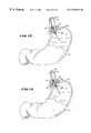
- FIG. 1is an anatomic view of the esophagus and stomach
- FIG. 2is a diagrammatic view of a system for treating body sphincters and adjoining tissue regions, which embodies features of the invention
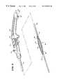
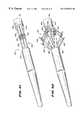
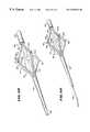
- FIG. 3is a perspective view, with portions broken away, of a device usable in association with the system shown in FIG. 1 having an operative element for contacting tissue shown in a collapsed condition;
- FIG. 4is a perspective view, with portions broken away, of the device shown in FIG. 3, with the operative element shown in an expanded condition;
- FIG. 5is a perspective view, with portions broken away, of the device shown in FIG. 3, with the operative element shown in an expanded condition and the electrodes extended for use;
- FIG. 6is an enlarged side view of the operative element when collapsed, as also shown in FIG. 3;
- FIG. 7is an enlarged side view of the operative element when expanded and with the electrodes extended for use, as also shown in FIG. 5 ;
- FIG. 8is an enlarged perspective view of an embodiment the operative element, when fully collapsed
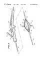
- FIG. 9is a side view of the deployment of a flexible endoscope through an esophageal introducer into the stomach;
- FIG. 10is an enlarged view of the endoscope shown in FIG. 9, retroflexed for viewing the cardia and lower esophageal sphincter;
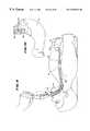
- FIG. 11is a side view of the deployment of the device shown in FIG. 3 after deployment of the flexible endoscope shown in FIG. 9, placing the operative element in the region of the lower esophageal sphincter;
- FIG. 12is an enlarged view of the operative element shown in FIG. 11, when placed in the region of the lower esophageal sphincter;
- FIG. 13is an enlarged view of the operative element shown in FIG. 11, when expanded into contact with muscosal tissue in the region of the lower esophageal sphincter;
- FIG. 14is an enlarged view of the operative element shown in FIG. 11, when expanded into contact with muscosal tissue in the region of the lower esophageal sphincter and with the electrodes extended to create lesions in the smooth muscle ring of the lower esophageal sphincter;
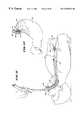
- FIG. 15is an enlarged view of the operative element shown in FIG. 11, when placed in the region of the cardia;
- FIG. 16is an enlarged view of the operative element shown in FIG. 11, when expanded into contact with muscosal tissue in the cardia;
- FIG. 17is an enlarged view of the operative element shown in FIG. 11, when expanded into contact with muscosal tissue in the cardia and with the electrodes extended to create lesions in the smooth muscle of the cardia;
- FIG. 18is an enlarged view of the operative element shown in FIG. 17, when fully deployed for creating lesions in the cardia;
- FIG. 19is an enlarged view of the operative element shown in FIG. 14 or FIG. 17, after being used to form lesions and in the process of being removed from the targeted tissue site;
- FIG. 20is a top view of a targeted tissue region in the cardia, showing a desired pattern of lesions
- FIG. 21is a perspective view of a “pear-shaped” operative element intended for deployment in the cardia, shown in a collapsed condition;
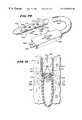
- FIG. 22is a perspective view of the “pear-shaped” shown in FIG. 21, shown in an expanded condition with the electrodes extended for use in an antegrade orientation;
- FIG. 23is an enlarged view of the operative element shown in FIG. 22, when expanded into contact with muscosal tissue in the cardia and with the electrodes extended to create lesions in the smooth muscle of the cardia;
- FIG. 24is a perspective view of the “pear-shaped” shown in FIG. 21, shown in an expanded condition with the electrodes extended for use in a retrograde orientation;
- FIG. 25is an enlarged view of the operative element shown in FIG. 24, when expanded into contact with muscosal tissue in the cardia and with the electrodes extended to create lesions in the smooth muscle of the cardia;
- FIG. 26is an enlarged side view a “disk-shaped” operative element intended for deployment in the cardia, when expanded into contact with muscosal tissue in the cardia and with the electrodes extended to create lesions in the smooth muscle of the cardia;
- FIGS. 27 and 28are an enlarged side views operative elements having different “peanut” shapes intended for deployment in the cardia, when expanded into contact with muscosal tissue in the cardia and with the electrodes extended to create lesions in the smooth muscle of the cardia;
- FIG. 29is an enlarged side view an operative element expanded into contact with muscosal tissue in the cardia and with “pig-tail” electrodes extended to create lesions in the smooth muscle of the cardia;
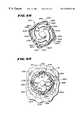
- FIG. 30is a enlarged perspective section view of an electrode having a cyindrical cross section
- FIG. 31is a enlarged perspective section view of an electrode having an elliptical cross section to resist twisting
- FIG. 32is a enlarged perspective section view of an electrode having a rectilinear cross section to resist twisting
- FIG. 33is an enlarged side view of an electrode deployed from an operative element in the region of the lower esophageal sphincter and having a collar to control the depth of tissue penetration;
- FIG. 34is a side section view of a stationary spine which comprises a portion of an operative element and which carries a movable electrode for creating lesion patterns;
- FIG. 35is a side section view of a stationary spine which comprises a portion of an operative element and which carries a pair of movable electrodes for creating lesion patterns
- FIG. 34is a side section view of a stationary spine which comprises a portion of an operative element and which carries a movable electrode for creating lesion patterns
- FIGS. 36 and 37are enlarged side views of operative elements deployed in the cardia and having movable spines for positioning either multiple electrodes or a single electrode in different positions for creating lesion patterns;
- FIG. 38is an enlarged side view of an operative element that carries a steerable electrode for creating lesions in body sphincters and adjoining tissue;
- FIG. 39is an enlarged side view of an operative element carrying surface electrodes for treating abnormal epithelial tissue in the gastrointestinal tract, the operative element being shown in a collapsed condition and deployed in the region of the lower esophageal sphincter;
- FIG. 40is an enlarged side view of the operative element shown in FIG. 39 and in an expanded condition contacting the abnormal epithelial tissue for applying ablation energy;
- FIG. 41is a perspective view of an operative element comprising a mechanically expandable basket shown in a collapsed condition
- FIG. 42is a perspective view of the operative element shown in FIG. 41, with the operative element shown in an expanded condition to extend the electrodes for use;
- FIG. 43is a side view showing a spine of the basket shown in FIG. 41 as it is mechanically flexed for penetrating tissue;
- FIG. 44is a side view of another operative element comprising a mechanically expandable basket shown in an expanded condition with the electrodes extended for use shown;
- FIG. 45is a side view of the operative element shown in FIG. 44 in a collapsed condition
- FIG. 46is a perspective view of an operative element that is deployed for use over a flexible endoscope, shown in a collapsed condition;
- FIG. 47is a perspective view of the operative element shown in FIG. 48 in an expanded condition and with the electrodes extended for use;
- FIG. 48is an enlarged view of the operative element shown in FIG. 47, when expanded into contact with muscosal tissue in the cardia and with the electrodes extended to create lesions in the smooth muscle of the cardia;
- FIG. 49is an end view of the operative element taken generally along line 49 — 49 in FIG. 48, as viewed from the retroflex endoscope over which the operative element is deployed for use;
- FIG. 50is a perspective view of the operative element of the type shown in FIG. 47, deployed over a flexible endoscope, and including a transparent region within the operative element to permit endoscopic viewing from within the operative element;
- FIG. 51is a perspective view of the operative element shown in FIG. 50, with the endoscope positioned within the operative element for viewing;
- FIG. 52is an enlarged view of an operative element comprising a mechanically expandable basket deployed over a flexible endoscope and with the electrodes penetrating the lower esophageal sphinter to create lesions;
- FIG. 53is a perspective view of an operative element for treating body sphincters and adjoining tissue regions, shown in an expanded condition with eight electrodes extended for use;
- FIG. 54is a perspective view of an operative element for treating body sphincters and adjoining tissue regions, shown in an expanded condition and four closely spaced electrodes extended for use;
- FIG. 55a perspective distal facing view of an operative element for treating body sphincters and adjoining tissue regions, shown a spine structure with cooling and aspiration ports located in the spines;
- FIG. 56a perspective proximal facing view of an operative element shown in FIG. 56;
- FIG. 57is a perspective view of a handle for manipulating the operative element shown in FIGS. 55 and 56;
- FIG. 58Aa perspective view of an operative element for treating body sphincters and adjoining tissue regions, shown a spine structure with cooling ports located in the spines and aspiration ports located in an interior lumen;
- FIG. 58Ba perspective view of an operative element for treating body sphincters and adjoining tissue regions, shown a spine structure with an underlying expandable balloon structure having pin hole ports which weep cooling liquid about the electrodes;
- FIG. 59a perspective view of an operative element for treating body sphincters and adjoining tissue regions, shown a spine structure with cooling ports located in the spines and an aspiration port located in its distal tip;
- FIG. 60a perspective view of the operative element shown in FIG. 59, deployed over a guide wire that passes through its distal tip;
- FIG. 61is a perspective view of a handle for manipulating the operative element over the guide wire, as shown in FIG. 60;
- FIG. 62a perspective view of an operative element for treating body sphincters and adjoining tissue regions, deployed through an endoscope;
- FIG. 63is a perspective view of an extruded tube that, upon further processing, will form an expandable basket structure
- FIG. 64is a perspective view of the extruded tube shown in FIG. 62 with slits formed to create an expandable basket structure;
- FIG. 65is the expandable basket structure formed after slitting the tube shown in FIG. 63;
- FIG. 66is a side section view of the esophagus, showing the folds of mucosal tissue
- FIG. 67is a perspective view of a device for treating body sphincters and adjoining tissue regions, which applies a vacuum to mucosal tissue to stabilize and present the tissue for the deployment of electrodes delivered by a rotating mechanism;
- FIG. 68is a section view of the rotating mechanism for deploying electrodes, taken generally along line 68 — 68 in FIG. 67 with the electrodes withdrawn;
- FIG. 69is a view of the rotating mechanism shown in FIG. 68, with a vacuum applied to muscosal tissue and the electrodes extended;
- FIG. 70is a perspective view of a device for treating body sphincters and adjoining tissue regions, which applies a vacuum to mucosal tissue to stabilize and present the tissue for the deployment of straight electrodes;
- FIG. 71is a side section view of the electrode deployment mechanism of the device shown in FIG. 70;
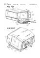
- FIGS. 72A and 72Bare, respectively, left and right perspective views of an integrated device for treating body sphincters and adjoining tissue regions, and having graphical user interface;
- FIG. 73is a front view of the device shown in FIGS. 72A and 72B showing the components of the graphical user interface;
- FIG. 74is a view of the graphical user interface shown in FIG. 73 showing the Standby screen before connection of a treatment device;
- FIG. 75is a view of the graphical user interface shown in FIG. 73 showing the Standby screen after connection of a treatment device;
- FIG. 76is a view of the graphical user interface shown in FIG. 73 showing the Standby screen after connection of a treatment device and after an electrode channel has been disabled by selection;
- FIG. 77is a view of the graphical user interface shown in FIG. 73 showing the Ready screen
- FIG. 78is a view of the graphical user interface shown in FIG. 73 showing the Ready screen while priming of cooling liquid takes place;
- FIG. 79is a view of the graphical user interface shown in FIG. 73 showing the RF-On screen;
- FIG. 80is a view of the graphical user interface shown in FIG. 73 showing the RF-On screen after an electrode channel has been disabled due to an undesired operating condition
- FIG. 81is a view of the graphical user interface shown in FIG. 73 showing the Pause screen
- FIG. 82is a schematic view of the control architecture that the integrated device and associated graphical user interface shown in FIGS. 72A, 72 B, and 73 incorporate;
- FIG. 83is an anatomic view of the esophagus and stomach, with portions broken away and in section, showing the location of a composite lesion pattern effective in treating GERD.
- This Specificationdiscloses various catheter-based systems and methods for treating dysfunction of sphincters and adjoining tissue regions in the body.
- the systems and methodsare particularly well suited for treating these dysfunctions in the upper gastrointestinal tract, e.g., in the lower esophageal sphincter and adjacent cardia of the stomach. For this reason, the systems and methods will be described in this context.
- the disclosed systems and methodsare applicable for use in treating other dysfunctions elsewhere in the body, which are not necessarily sphincter-related.
- the various aspects of the inventionhave application in procedures requiring treatment of hemorrhoids, or incontinence, or restoring compliance to or otherwise tightening interior tissue or muscle regions.
- the systems and methods that embody features of the inventionare also adaptable for use with systems and surgical techniques that are not necessarily catheter-based.
- the esophagus 10is a muscular tube that carries food from the mouth to the stomach 12 .
- the muscles in the walls of the esophagus 10contract in a wavelike manner, moving the food down to the stomach 12 .
- the interior wall of the esophagusincludes glands that secrete mucus, to aid in the movement of food by providing lubrication.
- the human esophagusis about twenty-five centimeters long.
- the stomach 12located in the upper left hand side of the abdomen, lays between the esophagus 10 and the small intestine 14 . In people and most animals, the stomach 12 is a simple baglike organ. A human being's stomach is shaped much like a J.
- the average adult stomachcan hold a little over one quart (0.95 liter).
- the stomach 12serves as a storage place for food. Food in the stomach 12 is discharged slowly into the intestines 14 . The stomach 12 also helps digest food.
- the upper end of the stomachconnects with the esophagus 10 at the cardiac notch 16 , at the top of the J-shape.
- the muscular ring called the lower esophageal sphincter 18surrounds the opening between the esophagus 10 and the stomach 12 .
- the funnel-shaped region of the stomach 12 immediately adjacent to the sphincter 18is called the cardia 20 .
- the cardia 20comprises smooth muscle. It is not a sphincter.
- the lower esophageal sphincter 18relaxes, or opens, to allow swallowed food to enter the stomach 12 .
- the lower esophageal sphincter 18is normally closed, to keep the stomach 12 contents from flowing back into the esophagus 10 .
- Another sphinctersurrounds the duodenal opening of the stomach 12 .
- the pyloric sphincter 22keeps non-liquid food material in the stomach 12 until it is processed into a more flowable, liquid form. The time that the stomach 12 retains food varies. Usually, the stomach 12 empties in three to five hours.
- the lower esophageal sphincter 18is subject to spontaneous relaxation.
- the sphincter 18opens independent of the normal swallowing function. Acidic stomach contents surge upward into the esophagus 10 , causing pain, discomfort, and damage the mucosal wall of the esophagus 10 .
- stomach 12distends to accommodate various food volumes. Over time, stomach distention can stretch the cardia 20 or otherwise cause loss of compliance in the cardia 20 . Loss of compliance in the cardia 20 can also pull the lower esophageal sphincter 18 open when the stomach 12 is distended, even absent sphincter muscle relaxation. The same undesired results occur: acidic stomach contents can surge upward into the esophagus 10 with the attendant undesired consequences.
- FIG. 1the views of the esophagus and stomach shown in FIG. 1 and elsewhere in the drawings are not intended to be strictly accurate in an anatomic sense.
- the drawingsshow the esophagus and stomach in somewhat diagrammatic form to demonstrate the features of the invention.
- FIG. 2shows a system 24 for diagnosing and/or treating dysfunction of the lower esophageal sphincter 18 and/or the adjoining cardia 20 of the stomach 12 .
- the system 24includes a treatment device 26 .
- the device 26includes a handle 28 made, e.g., from molded plastic.
- the handle 28carries a flexible catheter tube 30 .
- the catheter tube 30can be constructed, for example, using standard flexible, medical grade plastic materials, like vinyl, nylon, poly(ethylene), ionomer, poly(urethane), poly(amide), and poly(ethylene terephthalate).
- the handle 28is sized to be conveniently held by a physician, to introduce the catheter tube 30 into the esophagus 10 . The details of using the treatment device 28 will be described later.
- the handle 28 and the catheter tube 30can form an integrated construction intended for a single use and subsequent disposal as a unit.
- the handle 28can comprise a nondisposable component intended for multiple uses.
- the catheter tube 30 , and components carried at the end of the catheter tube 30(as will be described), comprise a disposable assembly, which the physician releasably connects to the handle 28 at time of use and disconnects and discards after use.
- the catheter tube 30can, for example, include a male plug connector that couples to a female plug receptacle on the handle 28 .
- the system 24may include an esophageal introducer 32 .
- the esophageal introducer 32is made from a rigid, inert plastic material, e.g., poly(ethylene) or polyvinyl chloride. As will be described later, the introducer 32 aids in the deployment of the catheter tube 30 into the esophagus 10 through the mouth and throat of a patient.
- the catheter tube 30may be deployed over a guide wire through the patient's mouth and pharynx, and into the esophagus 10 , without use of an introducer 32 , as will be described later. Still alternatively, the catheter tube 30 may be passed through the patient's mouth and pharynx, and into the esophagus 10 , without use of either a guide wire or introducer 32 .
- the catheter tube 30has a distal end 34 , which carries an operative element 36 .
- the operative element 36can take different forms and can be used for either therapeutic purposes, or diagnostic purposes, or both.
- the catheter tube 30can carry a protection sheath 472 (see FIG. 2) for the operative element 36 .
- the sheath 472slides along the catheter tube 30 (as indicated by arrows 473 in FIG. 2) between a forward position enclosing the operative element 36 and a rearward position free of the operative element 36 .
- the sheath 472prevents contact between tissue and the operative element 36 , thereby aiding in the deployment and removal of the operative element 36 through the patient's mouth and pharynx.
- the sheath 472frees the operative element 36 for use.
- the operative element 36can support, for example, a device for imaging body tissue, such as an endoscope, or an ultrasound transducer.
- the operative element 36can also support a device to deliver a drug or therapeutic material to body tissue.
- the operative element 36can also support a device for sensing a physiological characteristic in tissue, such as electrical activity, or for transmitting energy to stimulate or form lesions in tissue.
- one function that the operative element 36 shown in the illustrated embodiment performsis to apply energy in a selective fashion to a targeted sphincter or other body region, which, for the purpose of illustration, are identified as the lower esophageal sphincter 18 , or cardia 20 , or both.
- the applied energycreates one or more lesions, or a prescribed pattern of lesions, below the mucosal surface of the esophagus 10 or cardia 20 .
- the subsurface lesionsare formed in a manner that preserves and protects the mucosal surface against thermal damage.
- the system 24includes a generator 38 to supply the treatment energy.
- the generator 38supplies radio frequency energy, e.g., having a frequency in the range of about 400 kHz to about 10 mHz.
- radio frequency energye.g., having a frequency in the range of about 400 kHz to about 10 mHz.
- other forms of energycan be applied, e.g., coherent or incoherent light; heated or cooled fluid; resistive heating; microwave; ultrasound; a tissue ablation fluid; or cryogenic fluid.
- a cable 40 extending from the proximal end of the handle 28terminates with an electrical connector 42 .
- the cable 40is electrically coupled to the operative element 36 , e.g., by wires that extend through the interior of the handle 28 and catheter tube 30 .
- the connector 42plugs into the generator 38 , to convey the generated energy to the operative element 36 .
- the system 24also includes certain auxiliary processing equipment.
- the processing equipmentcomprises an external fluid delivery apparatus 44 and an external aspirating apparatus 46 .
- the catheter tube 30includes one or more interior lumens (not shown) that terminate in fittings 48 and 50 , located on the handle 28 .
- One fitting 40connects to the fluid delivery apparatus 44 , to convey processing fluid for discharge by or near the operative element 36 .
- the other fitting 50connects to the aspirating apparatus 46 , to convey aspirated material from or near from the operative element 36 for discharge.
- the system 24also includes a controller 52 .
- the controller 52which preferably includes a central processing unit (CPU), is linked to the generator 38 , the fluid delivery apparatus 44 , and the aspirating apparatus 46 .
- the aspirating apparatus 46can comprise a conventional vacuum source typically present in a physician's suite, which operates continuously, independent of the controller 52 .
- the controller 52governs the power levels, cycles, and duration that the radio frequency energy is distributed to the operative element 36 , to achieve and maintain power levels appropriate to achieve the desired treatment objectives. In tandem, the controller 52 also governs the delivery of processing fluid and, if desired, the removal of aspirated material.
- the controller 52includes an input/output (I/O) device 54 .
- the I/O device 54allows the physician to input control and processing variables, to enable the controller to generate appropriate command signals.
- the I/O device 54also receives real time processing feedback information from one or more sensors associated with the operative element (as will be described later), for processing by the controller 52 , e.g., to govern the application of energy and the delivery of processing fluid.
- the I/O device 54also includes a graphical user interface (GUI), to graphically present processing information to the physician for viewing or analysis. Further details regarding the GUI will be provided later.
- GUIgraphical user interface
- the structure of the operative element 36can vary. Various representative embodiments will be described.
- the operative element 36comprises a three-dimensional basket 56 .
- the basket 56includes one or more spines 58 , and typically includes from four to eight spines 58 , which are assembled together by a distal hub 60 and a proximal base 62 .
- the spines 58are equally circumferentially spaced apart in side-by-side pairs.
- Each spine 58preferably comprises a flexible tubular body made, e.g. from molded plastic, stainless steel, or nickel titanium alloy.
- the cross sectional shape of the spines 58can vary, possessing, e.g., a circular, elliptical, square, or rectilinear shape. In the illustrated embodiment, the spines 58 possess a rectilinear shape to resist twisting. Further examples of specific configurations for the spines 58 will be provided later.
- Each spine 58can be surrounded by a sleeve 64 (see FIG. 7) that is preferably textured to impart friction.
- sleeve 64includes knitted Dacron® material and Dacron® velour.
- Each spine 58carries an electrode 66 (see FIGS. 5 and 7 ).
- each electrode 66is carried within the tubular spine 58 for sliding movement.
- Each electrode 66slides from a retracted position, withdrawn in the spine 58 (shown in FIGS. 3, 4 , and 6 ), and an extended position, extending outward from the spine 58 (see FIGS. 5 and 7) through a hole in the spine 58 and sleeve 64 .
- a push-pull lever 68 on the handle 28is coupled by one or more interior wires to the sliding electrodes 66 .
- the lever 68controls movement electrodes between the retracted position (by pulling rearward on the lever 68 ) and the extended position (by pushing forward on the lever 68 ).
- the electrodes 66can be formed from various energy transmitting materials. In the illustrated embodiment, for deployment in the esophagus 10 or cardia 20 , the electrodes 66 are formed from nickel titanium. The electrodes 66 can also be formed from stainless steel, e.g., 304 stainless steel, or, as will be described later, a combination of nickel titanium and stainless steel. The electrodes 66 have sufficient distal sharpness and strength to penetrate a desired depth into the smooth muscle of the esophageal or cardia 20 wall. The desired depth can range from about 4 mm to about 5 mm.
- each electrode 66is preferably biased with a bend. Movement of the electrode 66 into the spine 58 overcomes the bias and straightens the electrode 66 .
- each electrode 66is normally biased with an antegrade bend (i.e., bending toward the proximal base 62 of the basket 56 ).
- each electrode 66can be normally biased toward an opposite retrograde bend (i.e., bending toward the distal hub 60 of the basket 58 ).
- an electrical insulating material 70is coated about the proximal end of each electrode 66 .
- the length of the material 70ranges from about 80 to about 120 mm.
- the insulating material 70can comprise, e.g., a Polyethylene Terephthalate (PET) material, or a polyimide or polyamide material.
- PETPolyethylene Terephthalate
- each electrode 66preferably presents an exposed, non-insulated conductive length of about 8 mm, providing an exposed surface area at the distal end of each electrode 66 of preferably about 0.1 mm 2 to 100 cm 2 .
- the material 70insulates the mucosal surface of the esophagus 10 or cardia 20 from direct exposure to the radio frequency energy. Thermal damage to the mucosal surface is thereby avoided. As will be described later, the mucosal surface can also be actively cooled during application of radio frequency energy, to further protect the mucosal surface from thermal damage.
- the ratio between exposed and insulated regions on the electrodes 66affects the impedance of the electrodes 66 during use. Generally speaking, the larger the exposed region is compared to the insulated region, a lower impedance value can be expected, leading to a fewer incidences of power shut-offs due to high impedance.
- spines 58 and/or electrodes 66can be present, and the geometric array of the spines 58 and electrodes 66 can vary.
- an expandable structure 72comprising a balloon is located within the basket 56 .
- the balloon structure 72can be made, e.g., from a Polyethylene Terephthalate (PET) material, or a polyamide (non-compliant) material, or a radiation cross-linked polyethylene (semi-compliant) material, or a latex material, or a silicone material, or a C-Flex (highly compliant) material.
- PETPolyethylene Terephthalate
- non-compliantnon-compliant
- radiation cross-linked polyethyleneor a latex material, or a silicone material, or a C-Flex (highly compliant) material.
- Non-compliant materialsoffer the advantages of a predictable size and pressure feedback when inflated in contact with tissue.
- Compliant materialsoffer the advantages of variable sizes and shape conformance to adjacent tissue geometries.
- the balloon structure 72presents a normally, generally collapsed condition, as FIGS. 3 and 6 show). In this condition, the basket 56 is also normally collapsed about the balloon structure 72 , presenting a low profile for deployment into the esophagus 10 .
- one end (hub 60 or base 62 ) of the basket 56can be arranged to slide longitudinally relative to the other end of the basket 56 , which is accordingly kept stationary.
- a stylet 74 attached to the slidable end of the basket 56(which, in FIG. 8, is the base 62 ) is controlled, e.g., by a push pull mechanism on the handle 28 .
- the stylet 74when pulled, serves to move the ends 58 and 60 of the basket 56 apart when the balloon structure 72 is collapsed.
- a full collapse of the basket 56is thereby possible (as FIG. 8 shows) to minimize the overall profile of the basket 56 for passage through the esophagus 10 .
- the push-pull mechanismcan include a lock to hold the stylet 74 stationary, to maintain the basket 56 in the fully collapsed condition during deployment.
- the catheter tube 30includes an interior lumen, which communicates with the interior of the balloon structure 72 .
- a fitting 76e.g., a syringe-activated check valve
- the fitting 76communicates with the lumen.
- the fitting 76couples the lumen to a syringe 78 (see FIGS. 4 and 5 ).
- the syringe 78injects fluid under pressure through the lumen into the balloon structure 72 , causing its expansion.
- Expansion of the balloon structure 72urges the basket 56 to open and expand (as FIGS. 4, 5 , and 7 show).
- the force exerted by the balloon structure 72when expanded, is sufficient to exert an opening force upon the tissue surrounding the basket 56 .
- the magnitude of the force exerted by the balloon structure 72is between about 0.01 to 0.5 lbs.
- the diameter of the balloon structure 72when expanded, can be optimized at about 2 cm to 3 cm.
- the diameter of the balloon structure 72when expanded, can be optimized at about 4 cm to about 6 cm.
- the controller 52conditions selected pairs of electrodes 66 to operate in a bipolar mode.
- one of the electrodescomprises the transmitter and the other electrode comprises the return for the transmitted energy.
- the bipolar electrode pairscan comprise adjacent side-by-side electrodes 66 on a given spine, or electrodes 66 spaced more widely apart on different spines.
- each electrode 66carries at least one temperature sensor 80 .
- Each electrodecan carry two temperature sensors 80 , one to sense temperature conditions near the exposed distal end of the electrode 66 , and the other to sense temperature conditions in the insulated material 70 .
- the second temperature sensor 80is located on the corresponding spine 58 , which rests against the muscosal surface when the balloon structure 72 is inflated.
- the patientlies awake in a reclined or semi-reclined position.
- the physicianinserts the esophageal introducer 32 through the throat and partially into the esophagus 10 .
- the introducer 32is pre-curved to follow the path from the mouth, through the pharynx, and into the esophagus 10 .
- the introducer 32also includes a mouth piece 82 , on which the patient bites to hold the introducer 32 in position.
- the introducer 32provides an open, unobstructed path into the esophagus 10 and prevents spontaneous gag reflexes during the procedure.
- the physicianneed not use the introducer 32 .
- a simple mouth piece 82upon which the patient bites, is used.
- the physicianpreferably first conducts a diagnostic phase of the procedure, to localize the site to be treated.
- a visualization devicecan be used for this purpose.
- the visualization devicecan comprise an endoscope 84 , or other suitable visualizing mechanism, carried at the end of a flexible catheter tube 86 .
- the catheter tube 86 for the endoscope 84includes measured markings 88 along its length. The markings 88 indicate the distance between a given location along the catheter tube 86 and the endoscope 84 .
- the physicianpasses the catheter tube 86 through the patient's mouth and pharynx, and into the esophagus 10 , while visualizing through the endoscope 84 .
- the physiciancan gauge, in either relative or absolute terms, the distance between the patient's mouth and the endoscope 84 in the esophagus 10 .
- the physicianvisualizes the desired treatment site (lower esophageal sphincter 18 or cardia 20 ) with the endoscope 84 , the physician records the markings 88 that align with the mouth piece 82 .
- the physiciannext begins the treatment phase of the procedure.
- the physicianpasses the catheter tube 30 carrying the operative element 36 through the introducer 32 .
- the expandable balloon structure 72is in its collapsed condition, and the electrodes 66 are in their retracted position.
- the physiciancan keep the endoscope 84 deployed for viewing the deployment of the operative element 36 , either separately deployed in a side-by-side relationship with the catheter tube 30 , or (as will be described later) by deployment through a lumen in the catheter tube 30 or deployment of the structure 72 through a lumen in the endoscope 84 itself. If there is not enough space for side-by-side deployment of the endoscope 84 , the physician deploys the endoscope 84 before and after deployment of the structure 72 .
- the catheter tube 30includes measured markings 90 along its length.
- the measured markings 90indicate the distance between a given location along the catheter tube 30 and the operative element 36 .
- the markings 90 on the catheter tube 30correspond in spacing and scale with the measured markings along the endoscope catheter tube 86 .
- the physiciancan thereby relate the markings 90 on the catheter tube 30 to gauge, in either relative or absolute terms, the location of the operative element 36 inside the esophagus 10 .
- the markings 90indicate that the operative element 36 is at the desired location (earlier visualized by the endoscope 84 )
- the physician stops passage of the operative element 36is now located at the site targeted for treatment.
- the targeted siteis shown to be the lower esophageal sphincter 18 .
- the targeted siteis shown to be the cardia 20 of the stomach 12 .
- the physicianoperates the syringe 78 to convey fluid or air into the expandable balloon structure 72 .
- the structure 72 , and with it, the basket 56expand, to make intimate contact with the mucosal surface, either with the sphincter (see FIG. 13) or the cardia 20 (FIG. 16 ).
- the expanded balloon structure 72serves to temporarily dilate the lower esophageal sphincter 18 or cardia 20 , to remove some or all the folds normally present in the mucosal surface.
- the expanded balloon structure 72also places the spines 58 in intimate contact with the mucosal surface.
- the physicianpushes forward on the lever 68 to move the electrodes 66 into their extended position.
- the electrodes 66pierce and pass through the mucosal tissue into the smooth muscle tissue of the lower esophageal sphincter 18 (FIG. 14) or cardia 20 (FIGS. 17 and 18 ).
- the physiciancommands the controller 52 to apply radio frequency energy between the transmitting and receiving electrodes 66 in each pair.
- the energycan be applied simultaneously by all pairs of electrodes 66 , or in any desired sequence.
- the energyohmically heats the smooth muscle tissue between the transmitting and return electrodes 66 .
- the controller 52samples temperatures sensed by the sensors 80 to control the application of energy.
- the controller 52can average the sensed temperature conditions or select the maximum temperature condition sensed for control purposes.
- the controller 52processes the sensed temperatures in a feedback loop to control the application of energy.
- the GUIcan also display the sensed temperatures and the applied energy levels. Alternatively, the physician can manually control the energy levels based upon the temperature conditions displayed on the GUI.
- energyis applied to achieve tissue temperatures in the smooth muscle tissue in the range of 55° C. to 95° C.
- tissue temperaturesin the smooth muscle tissue in the range of 55° C. to 95° C.
- lesionscan typically be created at depths ranging from one to four millimeters below the muscosal surface.
- Typical energiesrange, e.g., between 100 and 1000 joules per electrode pair.
- the lesionspossess sufficient volume to evoke tissue healing processes accompanied by intervention of fibroblasts, myofibroblasts, macrophages, and other cells.
- the healing processesresults in a contraction of tissue about the lesion, to decrease its volume or otherwise alter its biomechanical properties.
- the healing processesnaturally tighten the smooth muscle tissue in the sphincter 18 or cardia 20 .
- the bipolar nature of the energy path between the electrodes 66creates, for a given amount of energy, lesions of greater volume than is typically created in a monopolar fashion.
- a pattern of multiple lesionse.g., in rings along the targeted treatment site in the lower esophageal sphincter 18 or cardia 20 .
- a preferred pattern(shown in FIG. 20 for the cardia 20 ) comprises several rings 94 of lesions 96 about one centimeter apart, each ring 94 comprising at least eight lesions 96 .
- a preferred pattern 92comprise six rings 94 , each with eight lesions 96 .
- the rings 94are concentrically spaced about the opening funnel of the cardia 20 .
- the rings 94are axially spaced along the esophagus 10 .
- the physiciancan create a given ring pattern 92 by expanding the balloon structure 72 and extending the electrodes 66 at the targeted treatment site, to form a first set of four lesions.
- the physicianthen withdraws the electrodes 66 , collapses the balloon structure 72 , and rotates the catheter tube 30 by a desired amount.
- the physicianthen again expands the structure 72 and again extends the electrodes 66 , to achieve a second set of four lesions.
- the physicianrepeats this sequence until a desired ring 94 of lesions 96 is formed. Additional rings 94 of lesions 96 can be created by advancing the operative element axially, gauging the ring separation by the markings 90 on the catheter tube 30 .
- the bipolar operative element 36can be used in the manner described to treat both the cardia 20 and the lower esophageal sphincter 18 in a single procedure. Alternatively, the operative element 36 can be used in the manner described to treat either the cardia 20 or the lower esophageal sphincter 18 individually.
- At least one spine 58(and preferably all spines) includes an interior lumen 98 (see FIG. 7 ).
- the fluid delivery apparatus 44conveys processing fluid F through the lumen 98 for discharge at the treatment site.
- the processing fluid Fcan comprise, e.g., saline or sterile water, to cool the mucosal surface while energy is being applied by the electrode 66 to ohmically heat muscle beneath the surface.
- the catheter tube 30includes a distal tail 100 , which extends beyond the hub 60 of the basket 56 .
- An interior lumen 102extends through the tail 100 and the interior of the balloon structure 72 to connect to the fitting 48 .
- the aspirating apparatus 46draws aspirated material and the processing fluid through this lumen 102 for discharge.
- This arrangementprovides self-contained aspiration for the operative element 36 .
- the mouth piece 82 of the esophageal introducer 32in an alternative embodiment suited for treatment of the lower esophageal sphincter 18 outside the stomach 12 (see FIG. 11 ), includes an aspiration port 104 .
- the aspiration apparatus 46is coupled to this port 104 .
- processing fluid introduced at the treatment siteis drawn through the introducer 32 surrounding the catheter tube 30 and into the aspiration apparatus 46 for discharge.
- the operative element 36need not include the self contained, interior aspiration lumen 102 .
- the cardia 20presents a significantly different topology than the lower esophageal sphincter 18 .
- the surface area of the cardia 20is larger than the lower esophageal sphincter 18 .
- the surface area of the cardia 20expands with distance from the lower esophageal sphincter 18 .
- the cardia 20is therefore “funnel” shaped, compared to the more tubular shape of the lower esophageal sphincter 18 .
- the different topologiescan be accommodated by using a family of operative elements having different shapes.
- One such operative elementhas a size and geometry better suited for deployment in the lower esophageal sphincter 18 than the cardia 20 , if desired).
- Another such operative elementhas a larger size and different geometry better suited for deployment in the cardia 20 than the lower esophageal sphincter.
- the location and the orientation of optimal, intimate contact between an operative element and the targeted tissuealso differ in the cardia 20 , compared to the lower esophageal sphincter 18 .
- optimal, intimate contactoccurs generally about the mid-region of the operative element, to thereby conform to the generally tubular shape of the sphincter 18 .
- optimal, intimate contactoccurs generally more about the proximal end of operative device, to thereby conform to the funnel shape of the cardia 20 .
- FIGS. 21 to 23show an operative element 106 having a shaped geometry and electrode configuration well suited for use in the cardia 20 .
- the operative element 106shares many features of the operative element 36 shown in FIG. 5, and common reference numbers are thus assigned.
- the operative element 106comprises an array of spines 58 forming a basket 56 , which is carried at the distal end of a catheter tube 30 .
- the operative element 106includes electrodes 66 on the spines 58 that can be retracted (FIG. 21) or extended (FIG. 22 ). As illustrated, the electrodes 66 are likewise bent in an antegrade direction.
- the operative element 106includes an inner balloon structure 72 that expands to open the basket 56 and place it in intimate contact with the cardia 20 for extension of the electrodes 66 .
- the balloon structure 72when expanded, as shown in FIG. 22, possesses a preformed shape achieved e.g., through the use of conventional thermoforming or blow molding techniques.
- the structure 72possesses a “pear” shape, being more enlarged at its proximal end than at its distal end.
- This preformed pear shapepresents an enlarged proximal surface for contacting the cardia 20 (see FIG. 23 ).
- the preformed pear shapebetter conforms to the funnel shaped topography of the cardia 20 than a circular shape.
- the pear shapewhen in intimate contact with the cardia 20 , establishes a secure anchor point for the deployment of the electrodes 66 .
- the electrodes 66themselves are repositioned to take advantage of the pear shape of the underlying balloon structure 72 .
- the electrodes 66are positioned proximally closer to the enlarged proximal base of the structure 72 than to its distal end.
- the proximally located electrodes 66can also be bent in a retrograde bent direction on the pear-shaped element 106 .
- the physiciandeploys the operative element 106 into the stomach 12 .
- the physicianexpands the element 106 and then pulls rearward on the catheter tube 30 . This places the enlarged proximal base of the structure 106 in contact with the cardia 20 .
- the physiciannext extends the electrodes 66 into the cardia 20 and proceeds with the ablation process. Multiple lesion patterns can be created by successive extension and retraction of the electrodes, accompanied by rotation and axial movement of the catheter tube 30 to reposition the structure 106 .
- the physiciancan retroflex an endoscope, also deployed in the stomach 12 , to image the cardia 20 as deployment of the electrodes 66 and lesion formation occur. Typically, however, there is not enough space for side-by-side deployment of the endoscope, and the physician views the cardia 20 before and after the lesion groups are formed.
- FIGS. 23 and 25show, the purposeful proximal shaping of the operative element 106 and the proximal location of the antegrade or retrograde electrodes 66 make the operative element 106 well suited for use in the cardia 20 .
- the electrodes 66are not arranged in bipolar pairs. Instead, for purposes of illustration, the electrodes 66 are shown arranged in singular, spaced apart relation. In this arrangement, the electrodes 66 are intended for monopolar operation. Each electrode 66 serves as a transmitter of energy, and an indifferent patch electrode (not shown) serves as a common return for all electrodes 66 . It should be appreciated, however, the operative element 106 could include bipolar pairs of electrodes 66 as shown in FIG. 5, if desired.
- FIG. 26shows another operative element 108 shaped for deployment in the cardia 20 .
- This element 108shares many features with the element 36 shown in FIG. 5, and common reference numbers have also been assigned.
- the expandable balloon structure 72 within the element 108has been preformed, e.g., through the use of conventional thermoforming or blow molding techniques, to present a disk or donut shape.
- the disk shapealso provides an enlarged proximal surface for contacting the cardia 20 , to create a secure anchor for the deployment of the electrodes 66 .
- the physiciandeploys the operative element 108 into the stomach 12 , preferably imaging the cardia 20 as deployment occurs.
- the physicianexpands the disk-shaped element 108 and pulls rearward on the catheter tube 30 , to place the element 108 in contact with the cardia 20 .
- the physicianextends the electrodes into the cardia 20 and proceeds with the ablation process. Lesion patterns are formed by successive extension and retraction of the electrodes 66 , accompanied by rotation and axial movement of the catheter tube 30 .
- antegrade bent electrodes 66are proximally mounted about the disk-shaped expandable element 108 . Retrograde bent electrodes could also be deployed.
- FIGS. 27 and 28show another operative element 110 having a geometry well suited for deployment in the cardia 20 .
- the balloon structure 72 within the element 110is preformed, e.g., through the use of conventional thermoforming or blow molding techniques, to possesses a complex peanut shape.
- the complex shapeprovides multiple surface contact regions, both inside and outside the cardia 20 , to anchor the element 110 for deployment of the electrodes 66 .
- a reduced diameter portion 112 of the expanded structure 72contacts the lower esophageal sphincter region.
- a larger diameter main portion 114 of the expanded structure 72rests in intimate contact against the cardia 20 of the stomach 12 .
- the structure 72includes a first reduced diameter portion 116 to contact the esophagus 10 above the lower esophageal sphincter 18 .
- the structure 72includes a second reduced portion 118 to contact the lower esophageal sphincter 18 region of the esophagus 10 .
- the structureincludes a third, larger diameter main portion 120 to rest in intimate contact against the cardia 20 of the stomach 12 .
- the peanut shaped configurations shown in FIGS. 27 and 28provide multiple points of support for operative element 110 both inside and outside the stomach 12 , to thereby stabilize the electrodes.
- FIGS. 27 and 28antegrade bent electrodes 66 are shown deployed in the cardia 20 . Retrograde bent electrodes could also be deployed.
- the electrodes 66can be formed in various sizes and shapes. As FIG. 30 shows, the electrodes 66 can possess a circular cross sectional shape. However, the electrodes 66 preferably possess a cross section that provides increased resistance to twisting or bending as the electrodes penetrate tissue. For example, the electrodes 66 can possess a rectangular cross section, as FIG. 32 shows. Alternatively, the electrodes 66 can possess an elliptical cross section, as FIG. 31 shows. Other cross sections, e.g., conical or pyramidal, can also be used to resist twisting.
- the surface of the electrode 66can, e.g., be smooth, or textured, or concave, or convex.
- the preceding descriptiondescribes electrodes 66 bent in either an antegrade or retrograde direction over an arc of ninety degrees or less. The bend provides a secure anchorage in tissue. Retraction of the electrodes 66 into the spines 58 overcomes the bias and straightens the electrode 66 when not in use.
- the electrode 66is biased toward a “pig-tail” bend, which spans an arc of greater than ninety degrees.
- the increased arc of the bendenhances the tissue-gripping force, thereby providing a more secure anchorage in tissue.
- retraction of the electrodes 66 into the spines 58overcomes the bias and straightens the electrode 66 when not in use.
- a given electrode 66can comprise a hybrid of materials, e.g., stainless steel for the proximal portion and nickel titanium alloy for the distal portion.
- the nickel titanium alloyperforms best in a curved region of the electrode 66 , due to its super-elastic properties.
- the use of stainless steel in the proximal portioncan reduce cost, by minimizing the amount of nickel titanium alloy required.
- the different materialsmay be joined, e.g., by crimping, swaging, soldering, welding, or adhesive bonding, which provide electrical continuity between or among the various materials.
- the proximal portioncomprises an oval stainless steel tube, into which a distal curved region having a round cross section and made of nickel titanium is slipped and keyed to prevent mutual twisting.
- the depth of electrode penetrationcan also be controlled, to prevent puncture through the targeted tissue region.
- the push-pull lever 68 on the handle 28which controls movement electrodes 66 , can include a rachet 118 or detent mechanism (see FIG. 3) that provides a tactile indication of electrode advancement. For each click of the rachet mechanism 118 as the lever 68 is moved forward or rearward, the physician knows that the electrodes have traveled a set distance, e.g., 1 mm.
- the electrode 66can carry a limit collar 121 (see FIG. 33 ).
- the limit collar 121contacts surface tissue when a set maximum desired depth of electrode penetration has been reached.
- the contact between the collar 121 and surface tissueresists further advancement of the electrode 66 .
- the physiciansenses the contact between the collar 121 and surface tissue by the increased resistance to movement of the lever 68 .
- the physicianthereby knows that the maximum desired depth of tissue penetration has been reached and to extend the electrodes 66 no further.
- An electrical measurementcan also be made to determine penetration of an electrode 66 in tissue. For example, by applying electrical energy at a frequency (e.g., 5 kHz) less than that applied for lesion formation, impedance of a given electrode 66 can be assessed. The magnitude of the impedance varies with the existence of tissue penetration and the depth of tissue penetration. A high impedance value indicates the lack of tissue penetration. The impedance value is lowered to the extent the electrode penetrates the tissue.
- a frequencye.g., 5 kHz
- FIG. 34An alternative embodiment is shown in FIG. 34, which achieves creation of lesion patterns movement without axial and, if desired, rotational movement of the catheter tube 30 .
- the basket 56has an array of spines 58 , as generally shown, e.g., in FIG. 22 or 24 .
- each spine 58 in the alternative embodimentincludes an inner carrier 122 mounted for axial sliding movement within a concentric outer sleeve 124 .
- a push-pull stylet 126 controlled by another lever on the handle(not shown) axially moves the carrier 122 within the outer sleeve 124 (as shown by arrows 125 in FIG. 34 ).
- a tissue penetrating electrode 66 of the type already describedis supported by the carrier 122 .
- the electrode 66can be moved by the operator (using the handle-mounted lever 68 , as shown in FIG. 5) from a retracted position within the carrier 122 and an extended position, projecting from a guide hole 128 in the carrier 122 (which FIG. 34 shows).
- the electrode 66When in the extended position, the electrode 66 also projects through a window 130 in the outer sleeve 124 for tissue penetration.
- the window 130has a greater axial length than the guide hole 128 .
- the extended electrode 66can thereby be moved by moving the carrier 122 (as shown by arrows 127 in FIG. 34) and thereby positioned in a range of positions within the window 130 .
- the physicianmoves the carrier 122 so that the guide hole 128 is aligned with the leading edge of the window 130 .
- the push-pull stylet 126can be controlled, e.g., with a detent mechanism that stops forward advancement or otherwise gives a tactile indication when this alignment occurs. External markings on the handle can also visually provide this information.
- the physicianmoves the electrodes 66 into their respective extended position, to penetrate tissue. After energy sufficient to form a first ring pattern of lesions is applied, the physician withdraws the electrodes 66 into the carriers 122 .
- the physiciannow moves the electrodes 66 axially rearward, without moving the catheter tube 30 , by pulling the push-pull stylet 126 rearward. If desired, the physician can rotate the catheter tube 30 to achieve a different circumferential alignment of electrodes 66 .
- the detent mechanism or the likecan click or provide another tactile indication that the guide hole 128 in each spine is aligned with a mid portion of the respective window 130 . Markings on the handle can also provide a visual indication of this alignment.
- the physicianextends the electrodes 66 through the window 130 . This time, the electrode 66 penetrate tissue in a position axially spaced from the first ring of penetration. Energy is applied sufficient to form a second ring pattern of lesions, which likewise are axially spaced from the first ring. The physician withdraws the electrodes 66 into the carriers.
- the physiciancan now move the carriers 122 to move the guide holes 128 to a third position at the trailing edge of each window 130 , still without axially moving the catheter tube 30 .
- the catheter tube 30can be rotated, if desired, to achieve a different circumferential orientation.
- the physicianrepeats the above-described electrode deployment steps to form a third ring pattern of lesions.
- the physicianwithdraws the electrodes 66 into the carriers 122 and withdraws the basket 56 , completing the procedure.
- each carrier 122can hold more than one electrode 66 .
- the electrodes 66 on each carrier 122are extendable and retractable through axially spaced-apart guide holes 128 in the carrier 122 .
- the outer sleeve 124includes multiple windows 130 registering with the electrode guide holes 128 .
- the physicianis able to simultaneously create multiple ring patterns. Further, the physician can axially shift the electrodes 66 and create additional ring patterns by shifting the carrier 122 , and without axial movement of the catheter tube 30 .
- each spine 58comprises a stationary part of the basket 56 .
- an array of movable spines 132can be deployed along the expandable balloon structure 72 .
- the expandable structure 72is shown to have a disk-shaped geometry and is deployed in the cardia 20 of the stomach 12 .
- Two movable spines 132are shown for the purpose of illustration, but it should be appreciated that fewer or greater number of movable spines 132 could be deployed.
- the proximal ends of the spines 132are coupled, e.g., to a push-pull stylet on the handle (not shown). Under control of the physician, the spines 132 are advanced to a desired position along the structure 72 in the tissue contact region, as shown by arrows 133 in FIGS. 36 and 37.
- Each movable spine 132can carry a single electrode 66 (as FIG. 37 shows) or multiple electrodes 66 (as shown in FIG. 36 ). Regardless, each electrode 66 can be extended and retracted relative to the movable spine 132 .
- the physicianpositions the movable spines 132 and deploys the electrode 66 or electrodes to create a first lesion pattern in the contact region.
- the physiciancan relocate the movable spines 132 to one or more other positions (with or without rotating the catheter tube 30 ).
- the physiciancan form complex lesion patterns in the tissue contact region without axial movement of the catheter tube 30 .
- an operative element 134can comprise a catheter tube 30 that carries at its distal end a single mono-polar electrode 66 (or a bipolar pair of electrodes), absent an associated expandable structure.
- the distal end of the catheter tube 30includes a conventional catheter steering mechanism 135 to move the electrode 66 (or electrodes) into penetrating contact with a desired tissue region, as arrows 137 in FIG. 38 show).
- the electrode 66can carry a limit collar 121 (as also shown in FIG. 33) to resist advancement of the electrode 66 beyond a desired penetration depth.
- the physicianforms a desired pattern of lesions by making a succession of individual mono-polar or bipolar lesions.
- a given electrode 66 deployed by an operative device in a sphincter or other body regioncan also be used to deliver drugs independent of or as an adjunct to lesion formation.
- the electrode 66includes an interior lumen 136 (as FIG. 35 demonstrates for the purpose of illustration).
- a submucosal lesioncan be formed by injecting an ablation chemical through the lumen 136 , instead of or in combination with the application of ablation energy by the electrode.
- Any electrode 66 possessing the lumen 136can also be used to deliver drugs to the targeted tissue site.
- tissue growth factors, fibrosis inducers, fibroblast growth factors, or sclerosantscan be injected through the electrode lumen 136 , either without or as an adjunct to the application of energy to ablate the tissue.
- Tissue bulking of a sphincter regioncan also be achieved by the injection of collagen, dermis, cadaver allograft material, or PTFE pellets through the electrode lumen 136 .
- radio frequency energycan be applied to the injected bulking material to change its physical characteristics, e.g., to expand or harden the bulking material, to achieve a desired effect.
- the failure of a ring of musclee.g., the anal sphincter or the lower esophageal sphincter 18 , called achalasia
- an electrode 66 having an interior lumen 136carried by an operative device previously described.
- the electrode 66is deployed and extended into the dysfunctional sphincter muscle.
- a selected exotoxine.g., serotype A of the Botulinum toxin, can be injected through the electrode lumen 136 to produce a flaccid paralysis of the dysfunctional sphincter muscle.
- the electrode 66 carried by an operative devicecan also be conditioned to apply stimulant energy to nerve tissue coupled to the dysfunctional muscle.
- the stimulant energyprovides an observable positive result (e.g., a relaxation of the sphincter) when targeted nerve tissue is in the tissue region occupied by the electrode 66 .
- the observable positive resultindicates that position of the electrode 66 should be maintained while applying ablation energy to the nerve tissue.
- Application of the nerve ablation energycan permanently eliminate the function of a targeted nerve branch, to thereby inactivate a selected sphincter muscle. Further details of the application of ablation energy to nerve tissue can be found in co-pending application entitled “Systems And Methods For Ablating Discrete Motor Nerve Regions.”
- FIGS. 39 and 40show an operative element 138 for the treatment of this condition.
- the operative element 138includes an expandable balloon structure 140 carried at the distal end of a catheter tube 30 .
- FIG. 39shows the structure 140 deployed in a collapsed condition in the lower esophageal sphincter 18 , where the abnormal epithelium tissue condition forms.
- FIG. 40shows the structure 140 in an expanded condition, contacting the abnormal epithelium tissue.
- the structure 140carries an array of surface electrodes 142 .
- the surface electrodes 142are carried by an electrically conductive wire 144 , e.g., made from nickel-titanium alloy material.
- the wire 144extends from the distal end of the catheter tube 30 and wraps about the structure 140 in a helical pattern.
- the electrodes 142are electrically coupled to the wire 144 , e.g., by solder or adhesive.
- the balloon structure 140can have painted, coated, or otherwise deposited on it solid state circuitry to provide the electrical path and electrodes.
- Expansion of the balloon structure 140places the surface electrodes 142 in contact with the abnormal epithelium.
- the application of radio frequency energyohmically heats the tissue surface, causing necrosis of the abnormal epithelium.
- the desired effectis the ablation of the mucosal surface layer (about 1 mm to 1.5 mm), without substantial ablation of underlying tissue.
- the structure 140is then collapsed, and the operative element 138 is removed.
- FIG. 83shows a lesion pattern 500 that has demonstrated efficacy in treating GERD.
- the lesion pattern 500begins at the Z-line 502 , which marks the transition between esophageal tissue (which is generally white in color) and stomach tissue (which is generally pink in color).
- the tissue color change at or near the Z-line 502can be readily visualized using an endoscope.
- the lower esophageal sphincter 18(which is about 4 cm to 5 cm in length) extends above and below the Z-line 502 .
- the Z-line 502marks the high pressure zone of the lower esophageal sphincter 18 .
- the physicianmay encounter an overlap of sphincter muscle and cardia muscle.
- the lesion pattern 500extends about 2 cm to 3 cm from the Z-line 502 into the cardia 20 .
- the pattern 500comprises a high density of lesion rings 504 , spaced apart by about 5 mm, with from four to sixteen lesions in each ring 504 .
- Five rings 504 ( 1 ) to 504 ( 5 )are shown in FIG. 83 .
- the uppermost ring 504 ( 1 )(at or near the Z-line 502 ) contains eight lesions.
- the next three rings 504 ( 2 ) to 504 ( 4 )each contains twelve lesions.
- the lower most ring 504 ( 5 )contains eight lesions.
- the lesion pattern 500 formed in this transition region below the Z-line 502creates, upon healing, an overall desired tightening of the sphincter 18 and adjoining cardia 20 muscle, restoring a normal closure function.
- the pattern 500 formed in this transition regionmay also create a neurophysiologic effect, as well.
- the lesion pattern 500may interrupt infra- and supra-sphincter nerve conduction.
- the nerve pathway block formed by the lesion pattern 500may mediate pain due to high pH conditions that accompany GERD and may in other ways contribute to the overall reduction of spontaneous sphincter relaxation that the procedure provides.
- rotation or sequential movement of electrodes 66can achieve the desired complex lesion pattern 500 .
- overlapping lesionscan occur.
- the operative element 36can, e.g., carry a number of electrodes 66 sufficient to form all the desired lesions in a given circumferential ring with a single deployment.
- the operative element 36carries eight electrodes 66 .
- the electrodes 66are equally spaced about the circumference of the balloon structure 72 on eight spines 58 .
- each spine 58preferably includes an interior lumen with a port 98 to convey a cooling liquid like sterile water into contact with the mucosal surface of the the targeted tissue site.
- the generator 38can include eight channels to supply treatment energy simultaneously to the eight electrodes 66 .
- the generator 38 that supplies treatment energy simultaneously in four channels to four electrodes 66 shown, e.g., in FIG. 22,can be readily configured by the controller 52 to supply treatment energy to the eight electrodes 66 shown in FIG. 53 .
- pairs of electrodes 66are shorted together, so that each channel simultaneously powers two electrodes in a monopolar mode.
- the shorted electrodes 66are preferably located on adjacent spines 58 , but an adjacent relationship for shorted electrodes is not essential.
- Each electrode 66carries a temperature sensor 80 , coupled to the I/O device 54 of the controller 52 , as previously described.
- the controller 52alternatively samples the temperature sensed by the sensors 80 for each shorted pair of electrodes 66 .
- the controller 52selects the hottest sensed temperature to serve as the input to control the magnitude of power to both electrodes. Both electrodes receive the same magnitude of power, as they are shorted together.
- pairs of electrodes 66are shorted together, as described in the previous configuration, so that each channel simultaneously powers two electrodes in a monopolar mode.
- Each electrode 66carries a temperature sensor 80 and are coupled to the I/O device 54 of the controller 52 .
- the temperature sensors 80 for each shorted pair of electrodes 66are connected in parallel.
- the controller 52thus receives as input a temperature that is approximately the average of the temperatures sensed by the sensors 80 for each shorted pair of electrodes 66 .
- the controller 52can include an algorithm to process the input to achieve a weighted average.
- the controller 52uses this approximate average to control the magnitude of power to both electrodes. As previously stated, both electrodes receive the same magnitude of power, as they are shorted together.
- the controller 52includes a switch element, which is coupled to each electrode 66 and its associated temperature sensor 80 independently. In one position, the switch element couples the four channels of the generator 38 to four of the electrodes (Electrode Group A). In another position, the switch element couples the four channels of the generator 38 to another four of the electrodes (Electrode Group B).
- the electrodes of Group Acould be located on one side of the element 36 , and the electrodes of Group B could be located on the opposite side of the element 36 .
- the electrodes 66 of Groups A and Bcan be intermingled about the element 36 .
- the switch elementcan switch between Electrode Group A and Electrode Group B, either manually or automatically.
- the switchingcan occur sequentially or in a rapidly interspersed fashion.
- Electrode Group Ais selected, and the controller samples the temperatures sensed by each sensor 80 and individually controls power to the associated electrode 66 based upon the sensed temperature.
- the other Electrode Group Bis selected.
- the controllersamples the temperatures sensed by each sensor 80 and individually controls power to the associated electrode 66 based upon the sensed temperature.
- tissue heating effectsoccur as a result of the application of energy by Electrode Group B, the other Electrode Group A is selected, and so on. This mode may minimize overheating effects for a given electrode group.
- Electrode Groups A and Boccurs at greater time intervals between the application of energy, allowing tissue moisture to return to dessicated tissue between applications of energy.
- the controller 52conditions four electrodes 66 to be transmitters (i.e., coupled to the four channels of the generator 38 ) and conditions the other four electrodes to be returns (i.e., coupled to the energy return of the generator 38 ).
- the transmitter and return electrodesare preferably located on adjacent spines 58 , but this is not essential.
- the four returnscan be independent, with no common ground, so that each channel is a true, independent bipolar circuit. In another arrangement, the four returns are shorted to provide a single, common return.
- the controller 52samples temperatures sensed by the sensors 80 carried by each electrode 66 .
- the controller 52can average the sensed temperature conditions by each electrode pair.
- the controller 52can include an algorithm to process the input to achieve a weighted average. Alternatively, the controller 52 can select the maximum temperature condition sensed by each electrode pair for control purposes.
- the electrodes 66 used as return electrodescan be larger than the electrodes 66 used to transmit the energy. In this arrangement, the return electrodes need not carry temperature sensors, as the hottest temperature will occur at the smaller energy transmitting electrode.
- the operative element 36can, e.g., carry a number of electrodes 66 sufficient to form, in a single deployment, a partial arcuate segment of the full circumferential ring.
- the operative element 36carries four electrodes 66 in a closely spaced pattern spanning 135 degrees on four spines 58 .
- the physiciandeploys the element 36 and creates four lesions in a partial arcuate segment comprising half of the full circumferential ring.
- the physicianthen rotates the element 36 one-hundred and eighty degrees and creates four lesions in a partial arcuate segment that comprises the other half of the full circumferential ring.
- the physicianmay find that there is less chance of overlapping lesions by sequentially placing four lesions at 180 intervals, than placing four lesions at 90 degree intervals, as previously described.
- FIGS. 41 and 42show an operative element 146 suited for deployment in the lower esophageal sphincter 18 , cardia 20 , and other areas of the body.
- the operative element 146comprises an expandable, three-dimensional, mechanical basket 148 .
- the basket 148includes eight jointed spines 150 , although the number of spines 158 can, of course, vary.
- the jointed spines 150are pivotally carried between a distal hub 152 and a proximal base 154 .
- Each jointed spine 150comprises a body made from inert wire or plastic material.
- Elastic memory materialsuch as nickel titanium (commercially available as NITINOLTM material) can be used, as can resilient injection molded plastic or stainless steel.
- the jointed spines 150possess a rectilinear cross sectional shape. However, the cross sectional shape of the spines 150 can vary.
- Each jointed spine 150includes a distal portion 158 and a proximal portion 160 joined by a flexible joint 156 .
- the distal and proximal portions 158 and 160flex about the joint 156 .
- the spine portions 158 and 160 and joint 156are integrally formed by molding.
- the joint 156comprises a living hinge. of course, the spine portions 158 and 160 can be separately manufactured and joined by a mechanical hinge.
- a pull wire 162is attached to the distal hub 152 of the basket 148 .
- Pulling on the wire 162e.g., by means of a suitable push-pull control on a handle at the proximal end of the catheter tube 30 ) draws the hub 152 toward the base 154 .
- a push wire joined to the base 154can advance the base 154 toward the hub 152 . In either case, movement of the base 154 and hub 152 toward each other causes the spines 150 to flex outward about the joints 156 (as FIG. 42 shows).
- the basket 148opens, and its maximum diameter expands.
- Each joint 156carries an electrode 166 .
- the electrode 166can comprise an integrally molded part of the spine 150 , or it can comprise a separate component that is attached, e,g. by solder or adhesive, to the spine 150 .
- the electrode materialcan also be deposited or coated upon the spine 150 .
- the electrodes 166nest within the joints 156 in a lay flat condition (as FIG. 41 shows), essentially coplanar with the distal and proximal portions 158 and 160 of the spines 150 .
- FIG. 43As best shown in FIG. 43, as the basket 148 opens, flexure of the spines 150 about the joints 156 progressively swings the electrodes 166 outward into a position for penetrating tissue (designated T in FIG. 43 ).
- FIG. 43shows, flexure of a given spine 150 about the associated joint 156 swings the electrode 166 in a path, in which the angle of orientation of the electrode 166 relative to the spine progressively increases.
- the electrode 166 and the distal portion 158 of the spine 150become generally aligned in the same plane. Further expansion increases the radial distance between the basket axis 164 and distal tip of the electrode 166 (thereby causing tissue penetration), without significantly increasing the swing angle between the basket axis 164 and the electrode 166 (thereby preventing tissue tear).
- the electrode 166moves in virtually a linear path into tissue. It is thus possible to deploy the electrode in tissue simultaneously with opening the basket 148 .
- FIGS. 44 and 45show an operative element 168 comprising a spring biased basket 170 .
- the distal end of the catheter tube 30carries two electrodes 172 .
- a single electrode, or more than two electrodes,can be carried in the same fashion on the distal end of the catheter tube 30 .
- the electrodes 172are formed from a suitable energy transmitting materials, e.g stainless steel.
- the electrodes 172have sufficient distal sharpness and strength to penetrate a desired depth into the smooth muscle of the esophageal or cardia 20 wall.
- each electrode 172is coupled to the leaf spring 174 .
- the leaf spring 174normally biases the electrodes 172 in an outwardly flexed condition facing the proximal end of the catheter tube 30 (as FIG. 44 shows).
- An electrode cover 176is slidably mounted on the distal end of the catheter tube 30 .
- a stylet 178is coupled to the electrode cover 176 .
- the stylet 178is movable axially along the catheter tube 30 , e.g., by a lever on the handle at the proximal end of the catheter tube 30 .
- the electrode cover 176moves the electrode cover 176 over the electrodes 172 into the position shown in FIG. 45 .
- the cover 176encloses the electrodes 172 , pulling them inward against the distal end of the catheter tube 30 .
- the electrodes 172are maintained in a low profile condition for passage through the esophagus, e.g., through lower esophageal sphincter 18 and into a position slightly beyond the surface of the cardia 20 .
- Pushing on the stylet 178moves the electrode cover 176 toward a distal-most position beyond the electrodes 172 , as shown in FIG. 44 .
- the electrodes 172spring outward.
- the outward spring distance of electrodes 172depends upon the position of the cover 176 .
- the electrodes 172reach their maximum spring distance when the cover 176 reaches its distal-most position, as FIG. 44 shows.
- the distal ends of the electrodes 172are oriented proximally, to point, e.,g. toward the cardia 20 .
- each electrode 172With the electrodes 172 sprung outward, the physician pulls rearward on the catheter tube 30 .
- the electrodes 172penetrate the cardia 20 .
- the electrodesapply energy, forming subsurface lesions in the cardia 20 in the same fashion earlier described.
- the proximal region of each electrode 172is preferably enclosed by an electrical insulating material 70 , to prevent ohmic heated of the mucosal surface of the cardia 20 .
- the physiciancan move the catheter tube 30 forward, to advance the electrodes 172 out of contact with the cardia 20 .
- the physiciancan reorient the electrodes 172 .
- the physiciancan also adjust the position of the cover 176 to increase or decrease the diameter of the outwardly flexed electrodes 172 . Pulling rearward on the catheter tube 30 causes the electrodes to penetrate the cardia 20 in their reoriented and/or resized position. In this way, the physician can form desired ring or rings of lesion patterns, as already described.
- the physicianUpon forming the desired lesion pattern, the physician advances the electrodes 172 out of contact with the cardia 20 . The physician moves the cover 176 back over the electrodes 172 (as FIG. 45 shows). In this condition, the physician can withdraw the catheter tube 30 and operative element 168 from the cardia 20 and esophagus 10 , completing the procedure.
- FIGS. 63 to 65show another embodiment of an operative element 216 suited for deployment in the lower esophageal sphincter 18 , cardia 20 , and other areas of the body.
- the operative element 216comprises an expandable, extruded basket structure 218 (as FIG. 65 shows).
- the structure 218is first extruded (see FIG. 63) as a tube 224 with a co-extruded central interior lumen 220 .
- the tube 224also includes circumferentially spaced arrays 222 of co-extruded interior wall lumens. Each array 222 is intended to accommodate an electrode 66 and the fluid passages associated with the electrode 66 .
- each array 222one wall lumen accommodates passage of an electrode 66 and related wires. Another lumen in the array 222 is capable of passing fluids used, e.g. to cool the mucosal surface. Another lumen in the array 222 is capable of passing fluids aspirated from the targeted tissue region, if required.
- the tube wallis cut to form slits 230 between the lumen arrays 222 .
- Proximal and distal ends of the tubeare left without slits 230 , forming a proximal base 226 and a distal hub 228 .
- Appropriate ports 232are cut in the tube wall between the slits 230 to accommodate passage of the electrodes 66 and fluids through the wall lumens.
- the base 226is coupled to the distal end of a catheter tube 236 .
- a pull wire 234 passing through the interior lumen 220is attached to the distal hub 228 .
- Pulling on the wire 234e.g., by means of a suitable push-pull control on a handle at the proximal end of the catheter tube 236 ) draws the hub 228 toward the base 226 (as FIG. 65 shows).
- a push wire joined to the base 226can advance the base 226 toward the hub 228 .
- the central co-extruded lumen 220is sized to accommodate passage of a guide wire or an endoscope, as will be described in greater detail later.
- the operative element 36includes a means for applying a cooling liquid like sterile water to mucosal tissue at the targeted tissue region and for aspirating or removing the cooling liquid from the targeted tissue region.
- the spines 58extend between distal and proximal ends 60 and 62 of the element 36 , forming a basket 56 .
- Four spines 58are shown for purpose of illustration.
- An expandable balloon structure 72is located within the basket 56 , as already described.
- An inflation tube 204conveys a media to expand the structure 72 during use.
- each spine 58comprises three tubes 186 , 188 , and 190 .
- Each tube 186 , 188 , and 190has an interior lumen.
- the first tube 186includes an electrode exit port 192 (see FIG. 56 ).
- the electrode 66passes through the exit port 192 for deployment in the manner previously described.
- the second tube 188includes a cooling port 194 .
- the cooling liquidpasses through the cooling port 194 into contact with mucosal tissue.
- the cooling port 194is preferably situated on the outside (i.e., tissue facing) surface of the spine 58 , adjacent the electrode exit port 192 (see FIG. 56 ).
- the third tube 190includes an aspiration port 196 . Cooling liquid is aspirated through the port 196 .
- the port 196is preferably situated on the inside (i.e. facing away from the tissue) surface of the spine 58 .
- At least one of the aspiration ports 196is located near the distal end 60 of the element 36 , and at least one the aspiration ports 196 is located near the proximal end 62 of the element 36 .
- two aspiration portsare located near the distal end 60 , on opposite spines 58 (see FIG. 55 ).
- two aspiration portsare located near the proximal end 62 , on opposite spines 58 (see FIG. 56 ). This arrangement provides for efficient removal of liquid from the tissue region.
- the electrodes 66are commonly coupled to the control lever 198 on the handle 28 (see FIG. 57 ), to which the catheter tube 30 carrying the element 36 is connected.
- the lumen of the second tube 188communicates with a port 200 on the handle 28 .
- the port 200is coupled to a source of cooling fluid.
- the lumen of the third tube 190communicates with a port 202 on the handle 28 .
- the port 202is coupled to a vacuum source.
- the inflation tube 204communicates with a port 206 on the handle 28 .
- the port 206connects to a source of inflation media, e.g., air in a syringe.
- the spines 58each comprises at least two tubes 186 and 188 .
- the inflation tube 204extends through the expandable balloon structure 72 , between the distal and proximal ends 60 and 62 of the element 36 .
- Inflation ports 208communicate with a lumen within the tube 204 to convey the expansion media into the structure 72 .
- the first tube 186includes the electrode exit port 192 , through which the electrode 66 passes.
- the second tube 188includes the outside facing cooling port 194 , for passing cooling liquid into contact with mucosal tissue.
- At least one aspiration port 196communicates with a second lumen in the inflation tube 204 .
- two aspiration ports 196are provided, one near the distal end 60 of the element 36 , and the other near the proximal end 62 of the element 36 .
- the element 36 shown in FIG. 58Acan be coupled to the handle 28 shown in the FIG. 57 to establish communication between the tubes 188 and 204 in the manner already described.
- a sponge-like, liquid retaining material 320can be applied about each spine 58 over the electrode exit port 192 the cooling port 194 .
- the electrode 66passes through the spongy material 320 .
- cooling liquid passing through the cooling port 194is absorbed and retained by the spongy material 320 .
- the spongy material 320keeps the cooling liquid in contact with mucosal tissue at a localized position surrounding the electrode 66 .
- the spongy material 320also minimizes the aspiration requirements.
- the presence of the spongy material 320 to absorb and retain cooling liquidalso reduces the flow rate and volume of cooling liquid required to cool mucosal tissue, and could eliminate the need for aspiration altogether.
- the spines 58each comprises a single tube 186 , which includes the electrode exit port 192 , through which includes the electrode exit port 192 , through which the electrode 66 passes.
- the inflation tube 204 in FIG. 58Bextends through the expandable balloon structure 72 .
- Inflation ports 208communicate with a lumen within the tube 204 to convey the expansion media into the structure 72 .
- the expansion mediumcomprises the cooling liquid.
- a pumpconveys the cooling liquid into the structure 72 . Filling the structure 72 , the cooling liquid causes expansion.
- the structure 72further includes one or more small pin holes PH near each electrode 66 . The cooling liquid “weeps” through the pin holes PH, as the pump continuously conveys cooling liquid into the structure 72 . The cooling liquid contacts and cools tissue in the manner previously described.
- At least one aspiration port 196communicates with a second lumen in the inflation tube 204 to convey the cooling liquid from the treatment site.
- two aspiration ports 196are provided, one near the distal end 60 of the element 36 , and the other near the proximal end 62 of the element 36 .
- the spines 58each comprises at least two tubes 186 and 188 .
- the inflation tube 204 in FIG. 59extends through the expandable balloon structure 72 , between the distal and proximal ends 60 and 62 of the element 36 .
- Inflation ports 208communicate with a lumen within the tube 204 to convey the expansion media into the structure 72 .
- the first tube 186includes the electrode exit port 192 , through which the electrode 66 passes.
- the second tube 188includes the outside facing cooling port 194 , for passing cooling liquid into contact with mucosal tissue.
- the distal end 60 of the element 36includes an aspiration port 196 , which communicates with a second lumen in the inflation tube 204 .
- the element 36 shown in FIG. 58can be coupled to the handle 28 shown in the FIG. 57 to establish communication between the tubes 188 and 204 in the manner already described.
- the lumen in the inflation tube 204 used for aspirationcan be alternatively used to pass a guide wire 210 , as FIG. 60 shows.
- the guide wire 210is introduced through the aspiration port 202 on the handle 28 (as FIG. 61 shows).
- a guide wire 210can obviate the need for the introducer 32 previously described and shown in FIG. 9, which may in certain individuals cause discomfort.
- the physicianpasses the small diameter guide wire 210 through the patient's mouth and pharynx, and into the esophagus 10 to the targeted site of the lower esophageal sphincter or cardia.
- the physiciancan next pass the operative element 36 (see FIG. 60) over the guide wire 210 into position.
- the physiciancan also deploy an endoscope next to the guide wire 210 for viewing the targeted site and operative element 36 .
- the guide wire 210also makes possible quick exchanges of endoscope and operative element 36 over the same guide wire 210 .
- the guide wire 210can serve to guide the endoscope and operative element 36 to the targeted site in quick succession.
- mucosal tissue MTnormally lays in folds in the area of the lower esophageal sphincter 18 and cardia 20 , presenting a fully or at least partially closed closed path.
- various expandable structuresare deployed to dilate the mucosal tissue MT for treatment. When dilated, the mucosal tissue folds expand and become smooth, to present a more uniform surface for submucosal penetration of the electrodes 66 . The dilation mediates against the possibility that an electrode 66 , when deployed, might slide into a mucosal tissue fold and not penetrate the underlying sphincter muscle.
- FIGS. 67 to 69show an alternative treatment device 238 suited for deployment in the lower esophageal sphincter 18 , cardia 20 , and other regions of the body to direct electrodes 66 into targeted submucosal tissue regions.
- the device 238includes a handle 248 (see FIG. 67) that carries a flexible catheter tube 242 .
- the distal end of the catheter tube 242carries an operative element 244 .
- the operative element 244includes a proximal balloon 246 and a distal balloon 248 .
- the balloons 246 and 248are coupled to an expansion media by a port 276 on the handle 240 .
- An electrode carrier 250is located between the balloons 246 and 248 .
- the carrier 250includes a generally cylindrical housing 252 with an exterior wall 268 .
- the housing 252includes a series of circumferentially spaced electrode pods 256 . Each pod 256 extends radially outward of the wall 268 of housing 252 .
- each pod 256includes an interior electrode guide bore 258 .
- the guide bore 258extends in a curved path through the pod 256 and terminates with an electrode port 262 spaced outward from the wall of the housing.
- the housing 252also includes a series of suction ports 260 (see FIGS. 68 and 69 ). Each suction port 260 is located flush with the housing wall 268 close to an electrode port 262 . The suction ports 260 are coupled to a source of negative pressure through a port 274 on the handle 240 .
- a driver disk 254is mounted for rotation within the housing 252 . Electrodes 264 are pivotally coupled to the driver disk 254 on pins 266 arranged in an equally circumferentially spaced pattern.
- the electrodes 264can be formed from various energy transmitting materials, e.g., 304 stainless steel.
- the electrodes 264are coupled to the generator 38 , preferable through the controller 52 .
- the electrodes 264have sufficient distal sharpness and strength to penetrate a desired depth into the smooth muscle of the esophageal or cardia 20 apply energy from the generator 38 .
- an electrical insulating material 278(see FIGS. 68 and 69) is coated about the proximal end of each electrode 264 .
- the material 278insulates the mucosal surface of the esophagus 10 or cardia 20 from direct exposure to the radio frequency energy to prevent thermal damage to the mucosal surface.
- the mucosal surfacecan also be actively cooled during application of radio frequency energy, to further protect the mucosal surface from thermal damage.
- Each electrode 264is biased with a bend, to pass from the pin 266 in an arcuate path through the electrode guide bore 258 in the associated pod 256 .
- Rotation of the driver disk 254 in one direction(which is clockwise in FIG. 68) moves the electrodes 264 through the bores 258 outward of the carrier 250 (as FIG. 69 shows).
- Opposite rotation of the driver disk 254(which is counterclockwise in FIG. 68) moves the electrodes 264 through the bores 258 inward into the carrier 250 (as FIGS. 67 and 68 show).
- a drive shaft 270is coupled to the driver disk 254 to affect clockwise and counterclockwise rotation of the disk 254 .
- a control knob 272 on the handle 240(see FIG. 67) is coupled to the drive shaft 254 to extend and retract the electrodes 264 .
- the carrier 250is located at the desired treatment site, e.g., in the region of the lower esophageal sphincter 18 .
- the balloons 246 and 248are expanded to seal the esophagus in the region between the balloons 246 and 248 .
- a vacuumis then applied through the suction ports 260 .
- the vacuumevacuates air and fluid from the area of the esophageal lumen surrounding the carrier 250 . This will cause the surrounding mucosal tissue to be drawn inward against the wall 268 of the housing 252 (see FIG. 69 ), to conform and be pulled tightly against the pods 256 .
- the application of vacuum to draw mucosal tissue against the pods 256also prevents movement of the esophagus while the electrodes 264 penetrate tissue.
- the counter force of the vacuumresists tissue movement in the direction of electrode penetration.
- the vacuumanchors the surrounding tissue and mediates against the “tenting” of tissue during electrode penetration. Without tenting, the electrode 264 penetrates mucosal tissue fully, to obtain a desired depth of penetration.
- FIGS. 70 and 71show another alternative treatment device 280 suited for deployment in the lower esophageal sphincter 18 , cardia 20 , and other regions of the body to direct electrodes 66 into targeted submucosal tissue regions.
- the device 280includes a handle 282 (see FIG. 70) that carries a flexible catheter tube 284 .
- the distal end of the catheter tube 284carries an operative element 286 .
- the operative element 286includes a proximal balloon 288 and a distal balloon 290 .
- the balloons 288 and 290are coupled to an expansion media by a port 292 on the handle 284 .
- the carrier 294is located between the balloons 246 and 248 .
- the carrier 294includes a generally cylindrical housing 296 with an exterior wall 298 (see FIG. 71 ).
- the housing 296includes a series of circumferentially and axially spaced recesses 300 in the wall 298 (best shown in FIG. 70 ).
- an electrode guide bore 302extends through the wall 298 and terminates with an electrode port 304 in each recess 300 .
- the axis of each guide bore 302is generally parallel to the plane of the corresponding recess 300 .
- the housing 296also includes a series of suction ports 306 , one in each recess 300 .
- the suction ports 306are coupled to a source of negative pressure through a port 308 on the handle 282 .
- Electrodes 312are pivotally coupled to the mount 310 .
- the electrodes 312can be formed from various energy transmitting materials, e.g., 304 stainless steel.
- the electrodes 312are coupled to the generator 38 , preferable through the controller 52 .
- the electrodes 312have sufficient distal sharpness and strength to penetrate a desired depth into the smooth muscle of the esophageal or cardia 20 apply energy from the generator 38 .
- an electrical insulating material 314is coated about the proximal end of each electrode 312 .
- Each electrode 312is generally straight, to pass from the mount 310 through the electrode guide bore 302 .
- Axial movement of the mount 310 toward the guide bores 302extends the electrodes 312 outward into the recesses 300 , as FIG. 71 shows.
- Opposite axial movement of the mount 310withdraws the electrodes 312 through the bores 302 inward from recesses 300 (as FIG. 70 shows).
- a stylet 316(see FIG. 71) is coupled to the mount 310 to affect axial movement of the mount 310 .
- a push-pull control knob 318 on the handle 282is coupled to the stylet 316 to extend and retract the electrodes 264 .
- a spring loaded mechanismcan be used to “fire” the mount 310 to deploy the electrodes 312 .
- the carrier 294is located at the desired treatment site, e.g., in the region of the lower esophageal sphincter.
- the balloons 288 and 290are expanded to seal the esophagus in the region between the balloons 288 and 290 .
- a vacuumis then applied through the suction ports 292 .
- the vacuumevacuates air and fluid from the area of the esophageal lumen surrounding the carrier 294 . This will cause the surrounding mucosal tissue to be drawn inward into the recesses, to conform and be pulled tightly against the recesses 300 , as FIG. 71 shows.
- the application of vacuum to draw mucosal tissue into the recesses 300also anchors the carrier 294 in the esophagus while the electrodes 312 penetrate tissue.
- Ribs and the likecan also be provided in the recesses 300 or along the wall 298 of the housing 296 to enhance the tissue anchoring effect.
- the counter force of the vacuumresists tissue movement in the direction of electrode penetration.
- the vacuumanchors the surrounding tissue and mediates against the “tenting” of tissue during electrode penetration.
- the electrodes 312penetrates mucosal tissue fully, to obtain a desired depth of penetration.
- a separately deployed endoscope 84carried by a flexible catheter tube 86 , is used to visualize the targeted site.
- the operative element 36is deployed separately, by means of a separate catheter tube 30 .
- a treatment device 26is deployed over the same catheter tube 86 that carries the endoscope 84 .
- this arrangementuses the flexible catheter tube 86 of the endoscope 84 as a guide wire.
- the treatment device 26can carry any suitable operative element (which, for this reason, is generically designated OE in FIGS. 46 to 49 ).
- OEoperative element
- FIGS. 47 and 47show, the catheter tube 30 passes through and beyond the interior of the operative element OE.
- the catheter tube 30further includes a central lumen 180 , which is sized to accommodate passage of the flexible catheter tube 86 carrying the endoscope 84 .
- the operative element OEcan be passed over the catheter tube 86 to the targeted tissue region.
- the targeted regionis shown to be the cardia 20 .
- the endoscope 86extends distally beyond the operative element OE.
- the physiciancan continuously monitor the placement of the operative element OE, the extension of the electrodes 66 , and the other steps of the lesion formation process already described.
- the operative element OEincludes the expandable balloon structure 72 (see FIGS. 50 and 51 )
- the structure 72 and the extent of the catheter tube 30 passing through itcan be formed of a material that is transparent to visible light.
- the physiciancan retract the endoscope 84 into expandable structure 72 (as FIG. 51 shows). The physician can then monitor the manipulation of the operative element OE and other steps in the lesion formation process from within the balloon structure 72 .
- Any portion of the catheter tube 30can be made from a transparent material, so the physician can visualize at other locations along its length.
- the mechanically expanded basket 148(shown earlier in FIGS. 41 and 42) can be likewise be modified for deployment over the catheter tube 86 that carries the flexible endoscope 84 .
- the interior lumen 180extends through the catheter tube 30 , the basket 148 , and beyond the basket hub 152 .
- the lumen 180is sized to accommodate passage of the endoscope 84 .
- the endoscope 84itself can include an interior lumen 212 .
- a catheter tube 214like that previously shown in FIG. 38, can be sized to be passed through the interior lumen 212 of the endoscope 84 , to deploy a mono-polar electrode 66 (or a bipolar pair of electrodes) into penetrating contact with a desired tissue region.
- the electrode 66can carry a limit collar 121 to resist advancement of the electrode 66 beyond a desired penetration depth.
- a rigid endoscopecan be deployed through the esophagus of an anesthetized patient.
- Any operative element OEcan be deployed at the end of a catheter tube to the site identified by rigid endoscopy, to perform the treatment as described.
- the catheter tube on which the operative element is deployedneed not be flexible.
- the catheter tube that carries the operative element OEcan be rigid.
- the catheter tubecan be deployed separately from the endoscope.
- the catheter tubecan include an interior lumen sized to pass over the rigid endoscope.
- Fluoroscopycan also be used to visual the deployment of the operative element OE.
- the operative element OEis modified to carry one or more radiopaque markers 182 (as FIG. 24 shows) at one or more identifiable locations, e.g, at the distal hub 60 , or proximal base 62 , or both locations.
- the physiciancan track movement of the radiopaque markers 182 to monitor movement and deployment of the operative element OE.
- the physiciancan use endoscopic visualization, as previously described.
- the catheter tubecan carry an ultrasound transducer 184 (as FIG. 21 shows) adjacent the proximal or distal end of the operative element OE.
- the physiciancan observe the transesophageal echo as a real time image, as the operative element OE is advanced toward the lower esophageal sphincter 18 .
- the real time imagereflects the thickness of the esophageal wall.
- Loss of the transesophageal echomarks the passage of the ultrasound transducer 184 beyond lower esophageal sphincter 18 into the stomach 12 .
- the physicianpulls back on the catheter tube 30 , until the transesophageal echo is restored, thereby marking the situs of the lower esophageal sphincter 18 .
- the physiciancan proceed to expand the structure 72 , deploy the electrodes 66 , and perform the steps of procedure as already described. Changes in the transesophageal echo as the procedure progresses allows the physician to visualize lesion formation on a real time basis.
- GUIGraphical User Interface
- the radio frequency generator 38the controller 52 with I/O device 54 , and the fluid delivery apparatus 44 (for the delivery of cooling liquid) are integrated within a single housing 400 .
- the I/O device 54includes input connectors 402 , 404 , and 406 .
- the connector 402accepts an electrical connector 408 coupled to a given treatment device TD.
- the connector 404accepts an electrical connector 410 coupled to a patch electrode 412 (for mono-polar operation).
- the connector 406accepts an pneumatic connector 414 coupled to a conventional foot pedal 416 . These connectors 402 , 404 , and 406 couple these external devices to the controller 52 .
- the I/O device 54also couples the controller 54 to an array of membrane keypads 422 and other indicator lights on the housing 400 (see FIG. 73 ), for entering and indicating parameters governing the operation of the controller 52 .
- the I/O device 54also couples the controller 52 to a display microprocessor 474 , as FIG. 82 shows.
- the microprocessor 474comprises, e.g., a dedicated Pentium®-based central processing unit.
- the controller 52transmits data to the microprocessor 474 , and the microprocessor 474 acknowledges correct receipt of the data and formats the data for meaningful display to the physician.
- the dedicated display microprocessor 474exerts no control over the controller 52 .
- the controller 52comprises an 68 HC 11 processor having an imbedded operating system.
- the controller 52can comprise another style of processor, and the operating system can reside as process software on a hard drive coupled to the CPU, which is down loaded to the CPU during system initialization and startup.
- the display microprocessor 474is coupled to a graphics display monitor 420 .
- the controller 52implements through the display microprocessor 474 a graphical user interface, or GUI 424 , which is displayed on the display monitor 420 .
- the GUI 424can be realized, e.g., as a “C” language program implemented by the microprocessor 474 using the MS WINDOWSTM or NT application and the standard WINDOWS 32 API controls, e.g., as provided by the WINDOWSTM Development Kit, along with conventional graphics software disclosed in public literature.
- the display microprocessor 474is also itself coupled to a data storage module or floppy disk drive 426 .
- the display microprocessor 474can also be coupled to a keyboard, printer, and include one or more parallel port links and one or more conventional serial RS-232C port links or EthernetTM communication links.
- the fluid delivery apparatus 44comprises an integrated, self priming peristaltic pump rotor 428 with a tube loading mechanism, which are carried on a side panel of the housing 400 .
- Other types of non-invasive pumping mechanismscan be used, e.g., a syringe pump, a shuttle pump, or a diaphragm pump.
- the fluid delivery apparatus 44is coupled to the I/O device 54 via a pump interface 476 .
- the pump interface 476includes imbedded control algorithms that monitor operation of the pump rotor 428 .
- the pump interface 476can monitor the delivery of electrical current to the pump rotor 428 , to assure that the rotor 428 is operating to achieve a desired flow rate or range of flow rates during use, or, upon shut down, the rotor 428 has stopped rotation.
- An optical encoder or magnetic Halls effect monitorcan be used for the same purpose.
- a flow rate transducer or pressure transducer, or both, coupled to the pump interface 476can be placed in line along the pump tubing, or in the treatment device TD itself, to monitor flow rate.
- Flow rate information acquired from any one of these monitoring devicescan also be applied in a closed loop control algorithm executed by the controller 52 , to control operation of the pump rotor 428 .
- the algorithmcan apply proportional, integral, or derivative analysis, or a combination thereof, to control operation of the pump rotor 428 .
- the device 400can readily integrate the aspiration apparatus 46 by selectively reversing the flow direction of the pump rotor 428 (thereby creating a negative pressure) or by including an additional dedicated pump rotor or equivalent pumping mechanism to perform the aspiration function.
- the integrated generator 38has four independent radio frequency channels. Each channel is capable of supplying up to 15 watts of radio frequency energy with a sinusoidal waveform at 460 kHz. As before explained, the four channels of the generator 38 can operate four electrodes in either a monopolar or bipolar mode. As also explained earlier, the four channels can also be configured to operate eight electrodes either in a monopolar mode or a bipolar mode.
- the integrated controller 52receives two temperature measurements through the I/O device 54 for each channel, one from the tip of each electrode on the treatment device TD, and one from tissue surrounding the electrode.
- the controller 52can regulate power to the electrodes in a close-loop based upon the sensed tip temperature, or the sensed tissue temperature, or both, to achieve and maintain a targeted tip tissue temperature at each electrode.
- the controller 52can also regulate power to the pump rotor 428 in a closed-loop based upon the sensed tip temperature, or the sensed tissue temperature, or both, to achieve an maintain a targeted tissue temperature at each electrode.
- the physiciancan manually adjust the power level or pump speed based upon a visual display of the sensed tip and tissue temperatures.
- the membrane keypads 422 and other indicators on the front panel of the device 400show the various operational parameters and operating states and allow adjustments to be made.
- the keypads 422 and indicatorsinclude:
- Standby/Ready Button 430which allows switching from one mode of operation to another, as will be described later.
- Standby/Ready Indicator 432which displays a green light after the device 400 passes a self test upon start up.
- RF On Indicator 434which displays a blue light when radio frequency energy is being delivered.
- Fault Indicator 436which displays a red light when an internal error has been detected. No radio frequency energy can be delivered when the Fault Indicator 436 is illuminated.
- Target Duration Keys 438which allow increases and decreases in the target power duration at the start or during the course of a procedure.
- Target Temperature Keys 440which allow increases and decreases in the target temperature at the start or during the course of a procedure.
- Maximum Power Keys 442which allow increases and decreases in the maximum power setting at the start or during the course of a procedure.
- Channel Selection Keys 444which allow selection of any or all power channels.
- Coagulation Level Keys 446which manually increases and decreases the magnitude of the indicated depth of insertion of the electrodes within the esophagus. This depth is determined, e.g., by visually gauging the measured markings along the length of the catheter tube of the treatment device TD, as previously described.
- the coagulation levelcan be automatically detected by, e.g., placing optical, mechanical, or magnetic sensors on the mouth piece 82 , which detect and differentiate among the measured markings along the catheter tube of the treatment device TD to read the magnitude of the depth of insertion.
- Flow Rate and Priming Keys 448which allow for selection of three internally calibrated flow rates, low (e.g., 15 ml/min), medium (e.g., 30 ml/min), and high (e.g., 45 ml/min). Pressing and holding the “Up” key activates the pump at a high flow rate for priming, overruling the other flow rates until the “Up” key is released.
- the graphics display monitor 420comprises an active matrix LCD display screen located between the membrane keypads 422 and other indicators on the front panel.
- the GUI 424is implemented by showing on the monitor 420 basic screen displays. In the illustrated embodiment, these displays signify four different operating modes: Start-Up, Standby, Ready, RF-On, and Pause.
- the operating systemUpon boot-up of the CPU, the operating system implements the GUI 424 .
- the GUI 424displays an appropriate start-up logo and title image (not shown), while the controller 52 performs a self-test.
- a moving horizontal bar or the likecan be displayed with the title image to indicate the time remaining to complete the start-up operation.
- the Standby screenis displayed, as shown in FIG. 74 . No radio frequency energy can be delivered while the Standby screen is displayed.
- the Screen Icon 450is an icon in the left hand corner of the monitor 420 , which indicates the operating condition of the treatment device TD and its position inside or outside the esophagus.
- the treatment device TDis shown to be disconnected and outside the esophagus.
- Pressing the “Up” priming key 448to cause cooling liquid to flow through the treatment device TD, causes an animated priming stream PS to be displayed along the treatment device TD in the icon, as FIG. 73 shows.
- the animated priming stream PSis displayed in the Screen Icon 450 whenever the pump rotor 428 is operating to indicate the supply of cooling fluid through the treatment TD.
- the icons 452 to 462indicate current selected parameter values.
- the flow rate/priming icon 462shows the selected pump speed by highlighting a single droplet image (low speed), a double droplet image (medium speed), and a triple droplet image (high speed).
- a floppy disk icon 464that is normally dimmed, along with the coagulation level icon 460 , until a floppy disk is inserted in the drive 426 .
- the icons 460 and 464are illuminated (see FIG. 73 ), and data is saved automatically after each application of radio frequency energy (as will be described later).
- Electrode Icon 466There is also an Electrode Icon 466 .
- the Electrode Icon 466comprises an idealized graphical image, which spatially models the particular multiple electrode geometry of the treatment device TD selected to be deployed in the esophagus. As FIG. 74 shows, four electrodes are shown in the graphic image of the Icon 466 , which are also spaced apart by 90 degrees. This graphic image is intended to indicate that the selected treatment device TD has the geometry of the four-electrode configuration shown, e.g., in FIG. 5 .
- the Icon 466presents in a spatial display the magnitude of tip temperature as actually sensed (in outside box B 1 ) and the magnitude of tissue temperatures as actually sensed (in inside box B 2 ). Until a treatment device TD is connected, two dashes appear in the boxes B 1 and B 2 . The existence of a faulty electrode in the treatment device will also lead to the same display.
- the controller 52prohibits advancement to the Ready screen until numeric values register in the boxes B 1 and B 2 , as FIG. 75 shows.
- the display of numeric valuesindicate a functional treatment device TD.
- No boxes B 1 or B 2will appear in the Icon 466 for a given electrode if the corresponding electrode/channel has been disabled using the Channel Selection Keys 444 , as FIG. 76 shows.
- the physicianis able to manually select or deselect individual electrodes using the Selection Keys 444 in the Standby or Ready Modes, but not in the RF-On Mode.
- the controller 52can be configured to allow electrode selection while in the RF-On Mode, if desired.
- the physicianconnects the treatment device TD to the device 400 .
- the physiciancouples the source of cooling liquid to the appropriate port on the handle of the device TD (as previously described) and loads the tubing leading from the source of cooling liquid (e.g., a bag containing sterile water) in the pump rotor 428 .
- the physicianalso couples the aspiration source to the appropriate port on the handle of the treatment device TD (as also already described).
- the physicianalso couples the patch electrode 412 and foot pedal 416 .
- the physiciancan now deploy the treatment device TD to the targeted tissue region in the esophagus, in the manners previously described.
- the physicianextends the electrodes through mucosal tissue and into underlying smooth muscle.
- the physicianpresses the Standby/Ready Button 430 to advance the device 400 from Standby to Ready Mode.
- the controller 52commands the generator 38 to apply bursts of low level radio frequency energy through each electrode selected for operation. Based upon the transmission of these low level bursts of energy by each electrode, the controller 52 derives a local impedance value for each electrode.
- the impedance valueindicates whether or nor the given electrode is in desired contact with submucosal, smooth muscle tissue. The use of impedance measurements for this purpose has been previously explained.
- the Ready screenupdates the Screen Icon 450 to indicate that the treatment device TD is connected and deployed in the patient's esophagus.
- the Ready screenalso intermittently blinks the RF On Indicator 434 to indicate that bursts of radio frequency energy are being applied by the electrodes.
- the Ready screenalso updates the Electrode Icon 466 to spatially display in the inside and outside boxes B 1 and B 2 the actual sensed temperature conditions.
- the Ready screenalso adds a further outside box B 3 to spatially display the derived impedance value for each electrode.
- the controller 52prevents the application of radio frequency energy if any temperature reading is outside a selected range (e.g., 15 to 120 degrees C.).
- the physicianselects the “Up” key of the Flow Rate and Priming Keys 448 to operate the pump rotor 428 to prime the treatment device TD with cooling fluid.
- An animated droplet stream PSis displayed along the treatment device TD in the Icon 450 , in the manner shown in FIG. 75, to indicate the delivery of cooling liquid by the pump rotor 428 .
- the physiciancan affect changes to the parameter values for the intended procedure.
- the controller 52automatically adjusts to take these values into account in its control algorithms.
- the corresponding target duration icon 452 , target temperature icon 454 , maximum power icon 456 , channel selection icon 458 , coagulation level icon 460 , and flow rate/priming icon 462change accordingly to indicate the current selected parameter values.
- the physicianWhen the physician is ready to apply energy to the targeted tissue region, the physician presses the foot pedal 416 . In response, the device 400 advances from Ready to RF-On Mode, provided that all sensed temperatures are within the selected range.
- the controller 52activates the pump rotor 428 . Cooling liquid is conveyed through the treatment device TD into contact with mucosal tissue at the targeted site. At the same time, cooling liquid is aspirated from the treatment device TD in an open loop. During a predetermined, preliminary time period (e.g. 2 to 5 seconds) while the flow of cooling liquid is established at the site, the controller 52 prevents the application of radio frequency energy.
- a predetermined, preliminary time periode.g. 2 to 5 seconds
- the controller 52applies radio frequency energy through the electrodes.
- the RF-On screenshown in FIG. 79, is displayed.
- the RF-On screendisplays the Screen Icon 450 , indicate that the treatment device TD is connected and deployed in the patient's esophagus.
- the flow drop animation PSappears, indicating that cooling is taking place.
- a flashing radio wave animation RWalso appears, indicating that radio frequency energy is being applied.
- the RF On Indicator 434is also continuously illuminated to indicate that radio frequency energy is being applied by the electrodes.
- the RF-On screenalso updates the Electrode Icon 466 to display in the box B 1 the actual sensed tip temperature conditions.
- the RF-On screenalso displays the derived impedance value for each electrode in the boxes B 3 .
- the surface temperatureis no longer displayed in a numerical format in a box B 2 . Instead, a circle C 1 is displayed, which is color coded to indicate whether the surface temperature is less than the prescribed maximum (e.g., 45 degrees C.). If the surface temperature is below the prescribed maximum, the circle is colored an “acceptable” color, e.g., green. If the surface temperature is exceeds the prescribed maximum, the color of the circle changes to an “not acceptable” color, e.g., to red.
- the prescribed maximume.g. 45 degrees C.
- the boxes B 1 and B 3are also color coded to indicate compliance with prescribed limits. If the tip temperature is below the prescribed maximum (e.g., 100 degrees C.), the box B 1 is colored, e.g., green. If the tip temperature is exceeds the prescribed maximum, the box border thickens and the color of the box B 1 changes, e.g., to red. If the impedance is within prescribed bounds (e.g., between 25 ohms and 1000 ohms), the box B 3 is colored, e.g., grey. If the impedance is outside the prescribed bounds, the box border thickens and the color of the box B 3 changes, e.g., to red.
- the prescribed maximume.g. 100 degrees C.
- the box B 1is colored, e.g., green. If the tip temperature is exceeds the prescribed maximum, the box border thickens and the color of the box B 1 changes, e.g., to red.
- the box B 3is colored, e.g.
- Electrode Icon 466can also display in a box or circle the power being applied to each electrode in spatial relation to the idealized image.
- the RF-On screendisplays the target duration icon 452 , target temperature icon 454 , maximum power icon 456 , channel selection icon 458 , coagulation level icon 460 , and flow rate/priming icon 462 , indicating the current selected parameter values.
- the physiciancan alter the target duration or target temperature or maximum power and pump flow rate through the corresponding selection keys 438 , 440 , 442 , and 448 on the fly, and the controller 52 and GUI instantaneously adjust to the new parameter settings.
- the controller 52does not permit change of the channel/electrode while radio frequency energy is being applied, and, for this reason, the channel selection icon 458 is dimmed.
- the RF-On screenalso displays a real time line graph 468 to show changes to the temperature profile (Y-axis) over time (X-axis).
- the RF-On screenalso shows a running clock icon 470 , which changes appearance to count toward the target duration.
- a digital clock display CDis also shown, indicating elapsed time.
- the line graph 468displays four trending lines to show the minimum and maximum surface and tip temperature readings from all active electrodes.
- the time axis(X-axis) is scaled to one of five pre-set maximum durations, depending upon the set target duration. For example, if the target duration is 0 to 3 minutes, the maximum time scale is 3:30 minutes. If the target duration is 3 to 6 minutes, the maximum time scale is 3:1 seconds, and so on.
- the line graph 468displays two background horizontal bars HB 1 and HB 2 of different colors.
- the upper bar HB 1is colored, e.g., green, and is centered to the target coagulation temperature with a spread of plus and minus 10 degrees C.
- the lower bar HB 2is colored, e.g., red, and is fixed at a prescribed maximum (e.g., 40 degrees C.) to alert potential surface overheating.
- the line graph 468also displays a triangle marker TM of a selected color (e.g., red)(see FIG. 80) with a number corresponding to the channel/electrode that is automatically turned off by the controller 52 due to operation outside the selected parameters.
- a triangle marker TM of a selected colore.g., red
- the circle C 1 and boxes B 1 and B 3 for this electrode/channelare also modified in the electrode icon 466 when this situation occurs.
- the Electrode Icon 466can graphically display other types of status or configuration information pertinent to the treatment device TD.
- the Electrode Icon 466can display a flashing animation in spatial relation to the idealized electrodes to constantly remind the physician that the electrode is extended into tissue. The flashing animation ceases to be shown when the electrode is retracted. The flashing animation reminds the physician to retract the electrodes before removing the treatment device TD.
- the Electrode Icon 466can display another flashing animation when the expandable structure of the treatment device TD is expanded. The flashing animation reminds the physician to collapse the electrodes before removing the treatment device TD.
- the controller 52terminates the conveyance of radio frequency ablation energy to the electrodes and the RF-On screen changes into the Pause screen (see FIG. 81 ), due to any of the following conditions (i) target duration is reached, (ii) all channels/electrodes have an erroneous coagulation condition (electrode or surface temperature or impedance out of range), or (iii) manual termination of radio frequency energy application by pressing the foot pedal 416 or the Standby/Ready Button 430 .
- the running clock icon 470stops to indicate total elapsed time.
- the controller 52commands the continued supply of cooling liquid through the treatment device TD into contact with mucosal tissue at the targeted site.
- cooling liquidis aspirated from the treatment device TD in an open loop. This flow of cooling liquid continues for a predetermined time period (e.g. 2 to 5 seconds) after the supply of radio frequency ablation energy is terminated, after which the controller 52 stops the pump rotor 428 .
- the controller 52continues to supply intermittent bursts of low power radio frequency energy to acquire impedance information.
- the Pause screenis in most respects similar to the RF-On screen.
- the Pause screendisplays the Screen Icon 450 , to indicate that the treatment device TD is connected and deployed in the patient's esophagus.
- the flashing radio wave animationis not present, indicating that radio frequency energy is no longer being applied.
- the RF On Indicator 434is, however, intermittently illuminated to indicate that bursts of radio frequency energy are being applied by the electrodes to acquire impedance information.
- the RF-On screenalso updates the Electrode Icon 466 to display in the boxes B 1 and B 3 the actual sensed tip temperature and impedance conditions. However, no background color changes are registered on the Pause screen, regardless of whether the sensed conditions are without or outside the prescribed ranges.
- the Pause screencontinues to display the target duration icon 452 , target temperature icon 454 , maximum power icon 456 , channel selection icon 458 , coagulation level icon 460 , and flow rate/priming icon 462 , indicating the current selected parameter values.
- the real time temperature line graph 468continues to display the four trending lines, until the target duration is reached and five additional seconds elapse, to show the drop off of electrode temperature.
- pressing the Standby/Ready button 430returns the device 400 from the Pause back to the Ready mode.
- the floppy disk icon 464 and coagulation level icon 460are normally dimmed on the various screens, until a floppy disk is inserted in the drive 426 .
- the icons 460 and 464are illuminated, and data is saved automatically after each application of radio frequency energy.
- the controller 52downloads data to the disk each time it leaves the RF-On screen, either by default or manual termination of the procedure.
- the downloaded datacreates a procedure log.
- the logdocuments, by date of treatment and number of treatments, the coagulation level, the coagulation duration, energy delivered by each electrode, and the coolant flow rate.
- the procedure logalso records at pre-established intervals (e.g., every 5 seconds) the temperatures of the electrode tips and surrounding tissue, impedance, and power delivered by each electrode.
- the procedure logpreferably records these values in a spreadsheet format.
- the housing 400can carry an integrated printer, or can be coupled through the I/O device 54 to an external printer.
- the printerprints a procedure log in real time, as the procedure takes place.
Landscapes
- Health & Medical Sciences (AREA)
- Surgery (AREA)
- Engineering & Computer Science (AREA)
- Life Sciences & Earth Sciences (AREA)
- Biomedical Technology (AREA)
- Molecular Biology (AREA)
- Nuclear Medicine, Radiotherapy & Molecular Imaging (AREA)
- Plasma & Fusion (AREA)
- Physics & Mathematics (AREA)
- Heart & Thoracic Surgery (AREA)
- Medical Informatics (AREA)
- Otolaryngology (AREA)
- Animal Behavior & Ethology (AREA)
- General Health & Medical Sciences (AREA)
- Public Health (AREA)
- Veterinary Medicine (AREA)
- Cardiology (AREA)
- Surgical Instruments (AREA)
Abstract
Description
Claims (5)
Priority Applications (3)
| Application Number | Priority Date | Filing Date | Title |
|---|---|---|---|
| US09/304,733US6355031B1 (en) | 1998-02-19 | 1999-05-04 | Control systems for multiple electrode arrays to create lesions in tissue regions at or near a sphincter |
| PCT/US2000/012205WO2000066013A1 (en) | 1999-05-04 | 2000-05-02 | Control systems for multiple electrode arrays to create lesions in tissue regions at or near a sphincter |
| AU47002/00AAU4700200A (en) | 1999-05-04 | 2000-05-02 | Control systems for multiple electrode arrays to create lesions in tissue regions at or near a sphincter |
Applications Claiming Priority (2)
| Application Number | Priority Date | Filing Date | Title |
|---|---|---|---|
| US09/026,296US6009877A (en) | 1994-06-24 | 1998-02-19 | Method for treating a sphincter |
| US09/304,733US6355031B1 (en) | 1998-02-19 | 1999-05-04 | Control systems for multiple electrode arrays to create lesions in tissue regions at or near a sphincter |
Related Parent Applications (1)
| Application Number | Title | Priority Date | Filing Date |
|---|---|---|---|
| US09/026,296Continuation-In-PartUS6009877A (en) | 1994-06-24 | 1998-02-19 | Method for treating a sphincter |
Publications (1)
| Publication Number | Publication Date |
|---|---|
| US6355031B1true US6355031B1 (en) | 2002-03-12 |
Family
ID=23177751
Family Applications (1)
| Application Number | Title | Priority Date | Filing Date |
|---|---|---|---|
| US09/304,733Expired - LifetimeUS6355031B1 (en) | 1998-02-19 | 1999-05-04 | Control systems for multiple electrode arrays to create lesions in tissue regions at or near a sphincter |
Country Status (3)
| Country | Link |
|---|---|
| US (1) | US6355031B1 (en) |
| AU (1) | AU4700200A (en) |
| WO (1) | WO2000066013A1 (en) |
Cited By (111)
| Publication number | Priority date | Publication date | Assignee | Title |
|---|---|---|---|---|
| US6551310B1 (en) | 1999-11-16 | 2003-04-22 | Robert A. Ganz | System and method of treating abnormal tissue in the human esophagus |
| US6673070B2 (en)* | 1994-06-24 | 2004-01-06 | Curon Medical, Inc. | Sphincter treatment apparatus |
| US6699243B2 (en)* | 2001-09-19 | 2004-03-02 | Curon Medical, Inc. | Devices, systems and methods for treating tissue regions of the body |
| US20040087936A1 (en)* | 2000-11-16 | 2004-05-06 | Barrx, Inc. | System and method for treating abnormal tissue in an organ having a layered tissue structure |
| US20040215235A1 (en)* | 1999-11-16 | 2004-10-28 | Barrx, Inc. | Methods and systems for determining physiologic characteristics for treatment of the esophagus |
| US20040229757A1 (en)* | 2003-05-16 | 2004-11-18 | Eoff Larry S. | Methods and compositions for reducing the production of water and stimulating hydrocarbon production from a subterranean formation |
| US20040243122A1 (en)* | 2003-02-13 | 2004-12-02 | Coaptus Medical Corporation | Transseptal closure of a patent foramen ovale and other cardiac defects |
| US20050154386A1 (en)* | 2001-09-19 | 2005-07-14 | Curon Medical, Inc. | Devices, systems and methods for treating tissue regions of the body |
| US20050171524A1 (en)* | 2004-01-09 | 2005-08-04 | Barrx, Inc. | Devices and methods for treatment of luminal tissue |
| US20050187599A1 (en)* | 1994-05-06 | 2005-08-25 | Hugh Sharkey | Method and apparatus for controlled contraction of soft tissue |
| US20050183732A1 (en)* | 1999-05-18 | 2005-08-25 | Edwards Stuart D. | Surgical weight control device |
| US20050234445A1 (en)* | 2002-03-05 | 2005-10-20 | Baylis Medical Company Inc. | Method of treating biological tissue |
| US20050267493A1 (en)* | 2001-02-06 | 2005-12-01 | Schreck Stefan G | Method and system for tissue repair using dual catheters |
| US20060079870A1 (en)* | 2004-10-07 | 2006-04-13 | Barry Robert L | Systems and methods for shrinking and/or securing cardiovascular tissue |
| US20060095032A1 (en)* | 1999-11-16 | 2006-05-04 | Jerome Jackson | Methods and systems for determining physiologic characteristics for treatment of the esophagus |
| US20060122680A1 (en)* | 2003-02-13 | 2006-06-08 | Auth David C | Systems and methods for securing cardiovascular tissue |
| US20060137698A1 (en)* | 1998-06-10 | 2006-06-29 | Asthmatx, Inc. | Methods for treating airways |
| WO2006088578A1 (en)* | 2005-02-03 | 2006-08-24 | Inventio Llc | Methods and devices for selective endoscopic retrograde cholangiopancreatography |
| US20060229687A1 (en)* | 2005-04-11 | 2006-10-12 | Medtronic, Inc. | Shifting between electrode combinations in electrical stimulation device |
| US20060247746A1 (en)* | 2005-04-21 | 2006-11-02 | Asthmatx, Inc. | Control methods and devices for energy delivery |
| US20060247727A1 (en)* | 2000-10-17 | 2006-11-02 | Asthmatx, Inc. | Control system and process for application of energy to airway walls and other mediums |
| US20060259028A1 (en)* | 1996-10-11 | 2006-11-16 | Utley David S | System for Tissue Ablation |
| USD533875S1 (en) | 2003-10-17 | 2006-12-19 | Nuvasive, Inc. | Graphic user interface for a medical monitor |
| US20070005049A1 (en)* | 2005-06-30 | 2007-01-04 | Comben Richard H | Apparatus and Method of Treating Urinary Incontinence by Heating Urethra |
| US20070083192A1 (en)* | 2005-10-07 | 2007-04-12 | Eric Welch | Apparatus and method for ablation of targeted tissue |
| US20070093805A1 (en)* | 2005-10-17 | 2007-04-26 | Coaptus Medical Corporation | Systems and methods for securing cardiovascular tissue, including via asymmetric electrodes |
| US20070100390A1 (en)* | 2000-10-17 | 2007-05-03 | Asthmatx, Inc. | Modification of airways by application of energy |
| US20070106296A1 (en)* | 1997-04-07 | 2007-05-10 | Asthmatx, Inc. | Expandable electode devices and methods of treating bronchial tubes |
| US20070118104A1 (en)* | 2005-11-23 | 2007-05-24 | Wallace Michael P | Auto-aligning ablating device and method of use |
| US20070123958A1 (en)* | 1998-06-10 | 2007-05-31 | Asthmatx, Inc. | Apparatus for treating airways in the lung |
| US20070129720A1 (en)* | 2002-04-08 | 2007-06-07 | Ardian, Inc. | Methods and apparatus for performing a non-continuous circumferential treatment of a body lumen |
| US20070142884A1 (en)* | 2005-12-16 | 2007-06-21 | Acoustx Corporation | Methods and apparatuses for treating an esophageal disorder such as gastroesophageal reflux disease |
| US20070142699A1 (en)* | 2005-12-16 | 2007-06-21 | Acoustx Corporation | Methods and implantable apparatuses for treating an esophageal disorder such as gastroesophageal reflux disease |
| US7294127B2 (en) | 2002-03-05 | 2007-11-13 | Baylis Medical Company Inc. | Electrosurgical tissue treatment method |
| US20080215047A1 (en)* | 2005-07-22 | 2008-09-04 | Fiab S.P.A. | Esophageal Electrocatheter |
| US20080275360A1 (en)* | 2004-05-04 | 2008-11-06 | Lars Fandriks | Arrangement and Method for Assessing the Motility of a Generally Tubular Anatomical Organ |
| US20090012518A1 (en)* | 2007-07-06 | 2009-01-08 | Utley David S | Method and Apparatus for Ablation of Benign, Pre-Cancerous and Early Cancerous Lesions That Originate Within the Epithelium and are Limited to the Mucosal Layer of the Gastrointestinal Tract |
| US20090012513A1 (en)* | 2007-07-06 | 2009-01-08 | Utley David S | Ablation in the Gastrointestinal Tract to Achieve Hemostasis and Eradicate Lesions With a Propensity for Bleeding |
| US20090018538A1 (en)* | 2007-07-12 | 2009-01-15 | Asthmatx, Inc. | Systems and methods for delivering energy to passageways in a patient |
| US20090030477A1 (en)* | 2007-07-24 | 2009-01-29 | Asthmatx, Inc. | System and method for controlling power based on impedance detection, such as controlling power to tissue treatment devices |
| US20090069797A1 (en)* | 1997-04-07 | 2009-03-12 | Asthmatx, Inc. | Bipolar devices for modification of airways by transfer of energy |
| US7519431B2 (en) | 2005-04-11 | 2009-04-14 | Medtronic, Inc. | Shifting between electrode combinations in electrical stimulation device |
| US20090143705A1 (en)* | 1997-04-07 | 2009-06-04 | Asthmatx, Inc. | Modification of airways by application of ultrasound energy |
| US20090318914A1 (en)* | 2008-06-18 | 2009-12-24 | Utley David S | System and method for ablational treatment of uterine cervical neoplasia |
| US7921855B2 (en) | 1998-01-07 | 2011-04-12 | Asthmatx, Inc. | Method for treating an asthma attack |
| US7959627B2 (en) | 2005-11-23 | 2011-06-14 | Barrx Medical, Inc. | Precision ablating device |
| US20110190761A1 (en)* | 2006-09-28 | 2011-08-04 | Covidien Ag | Temperature Sensing Return Electrode Pad |
| US7992572B2 (en) | 1998-06-10 | 2011-08-09 | Asthmatx, Inc. | Methods of evaluating individuals having reversible obstructive pulmonary disease |
| US7997278B2 (en) | 2005-11-23 | 2011-08-16 | Barrx Medical, Inc. | Precision ablating method |
| US20110257646A1 (en)* | 1999-07-14 | 2011-10-20 | Mederi Therapeutics Inc. | Method for treating fecal incontinence |
| US20120029308A1 (en)* | 2010-07-27 | 2012-02-02 | Carefusion 303, Inc. | System and method for monitoring body temperature of a person |
| US8177781B2 (en) | 2000-10-02 | 2012-05-15 | Novasys Medical, Inc. | Apparatus and methods for treating female urinary incontinence |
| US8235980B2 (en) | 2007-05-07 | 2012-08-07 | Tyco Healthcare Group Lp | Electrosurgical system for measuring contact quality of a return pad |
| US8251070B2 (en) | 2000-03-27 | 2012-08-28 | Asthmatx, Inc. | Methods for treating airways |
| US8251992B2 (en) | 2007-07-06 | 2012-08-28 | Tyco Healthcare Group Lp | Method and apparatus for gastrointestinal tract ablation to achieve loss of persistent and/or recurrent excess body weight following a weight-loss operation |
| US8273012B2 (en) | 2007-07-30 | 2012-09-25 | Tyco Healthcare Group, Lp | Cleaning device and methods |
| US8301265B2 (en) | 2007-09-10 | 2012-10-30 | Medtronic, Inc. | Selective depth electrode deployment for electrical stimulation |
| US8403927B1 (en) | 2012-04-05 | 2013-03-26 | William Bruce Shingleton | Vasectomy devices and methods |
| US8430873B2 (en) | 2007-08-01 | 2013-04-30 | Covidien Lp | System and method for return electrode monitoring |
| US8443810B2 (en) | 1998-06-10 | 2013-05-21 | Asthmatx, Inc. | Methods of reducing mucus in airways |
| US8483831B1 (en) | 2008-02-15 | 2013-07-09 | Holaira, Inc. | System and method for bronchial dilation |
| US20130211179A1 (en)* | 2003-08-27 | 2013-08-15 | Suros Surgical Systems, Inc. | System and method for minimally invasive disease therapy |
| US20130217964A1 (en)* | 2012-02-16 | 2013-08-22 | Terumo Kabushiki Kaisha | Expansion catheter |
| US8518036B2 (en) | 2002-03-05 | 2013-08-27 | Kimberly-Clark Inc. | Electrosurgical tissue treatment method |
| US8641711B2 (en) | 2007-05-04 | 2014-02-04 | Covidien Lp | Method and apparatus for gastrointestinal tract ablation for treatment of obesity |
| US8646460B2 (en) | 2007-07-30 | 2014-02-11 | Covidien Lp | Cleaning device and methods |
| US8696661B2 (en) | 1998-02-19 | 2014-04-15 | Mederi Therapeutics Inc. | Systems and methods for treating dysfunctions in the intestines and rectum that adapt to the anatomic form and structure of different individuals |
| US8740895B2 (en) | 2009-10-27 | 2014-06-03 | Holaira, Inc. | Delivery devices with coolable energy emitting assemblies |
| US8784338B2 (en) | 2007-06-22 | 2014-07-22 | Covidien Lp | Electrical means to normalize ablational energy transmission to a luminal tissue surface of varying size |
| US8808280B2 (en) | 2008-05-09 | 2014-08-19 | Holaira, Inc. | Systems, assemblies, and methods for treating a bronchial tree |
| US8882755B2 (en) | 2002-03-05 | 2014-11-11 | Kimberly-Clark Inc. | Electrosurgical device for treatment of tissue |
| US20140336639A1 (en)* | 2004-10-28 | 2014-11-13 | Boston Scientific Scimed, Inc. | Ablation probe with flared electrodes |
| US8894646B2 (en) | 1998-02-19 | 2014-11-25 | Mederi Therapeutics, Inc. | Sphincter treatment apparatus |
| US8911439B2 (en) | 2009-11-11 | 2014-12-16 | Holaira, Inc. | Non-invasive and minimally invasive denervation methods and systems for performing the same |
| US9023031B2 (en) | 1997-08-13 | 2015-05-05 | Verathon Inc. | Noninvasive devices, methods, and systems for modifying tissues |
| US9149328B2 (en) | 2009-11-11 | 2015-10-06 | Holaira, Inc. | Systems, apparatuses, and methods for treating tissue and controlling stenosis |
| US20150335331A1 (en)* | 2014-05-21 | 2015-11-26 | The Regents Of The University Of Michigan | Fenestrated decoupling system for internal selective attachment to soft tissue organs |
| US9204921B2 (en) | 2012-12-13 | 2015-12-08 | Cook Medical Technologies Llc | RF energy controller and method for electrosurgical medical devices |
| US9272132B2 (en) | 2012-11-02 | 2016-03-01 | Boston Scientific Scimed, Inc. | Medical device for treating airways and related methods of use |
| US9283374B2 (en) | 2012-11-05 | 2016-03-15 | Boston Scientific Scimed, Inc. | Devices and methods for delivering energy to body lumens |
| US9292152B2 (en) | 2009-09-22 | 2016-03-22 | Mederi Therapeutics, Inc. | Systems and methods for controlling use and operation of a family of different treatment devices |
| US9339618B2 (en) | 2003-05-13 | 2016-05-17 | Holaira, Inc. | Method and apparatus for controlling narrowing of at least one airway |
| US9364277B2 (en) | 2012-12-13 | 2016-06-14 | Cook Medical Technologies Llc | RF energy controller and method for electrosurgical medical devices |
| US9398933B2 (en) | 2012-12-27 | 2016-07-26 | Holaira, Inc. | Methods for improving drug efficacy including a combination of drug administration and nerve modulation |
| US9408662B2 (en) | 2012-05-07 | 2016-08-09 | Cook Medical Technologies Llc | Sphincterotome having expandable tines |
| US9420952B2 (en) | 2010-07-27 | 2016-08-23 | Carefusion 303, Inc. | Temperature probe suitable for axillary reading |
| US9474573B2 (en) | 2002-03-05 | 2016-10-25 | Avent, Inc. | Electrosurgical tissue treatment device |
| US9474565B2 (en) | 2009-09-22 | 2016-10-25 | Mederi Therapeutics, Inc. | Systems and methods for treating tissue with radiofrequency energy |
| US9585620B2 (en) | 2010-07-27 | 2017-03-07 | Carefusion 303, Inc. | Vital-signs patch having a flexible attachment to electrodes |
| US9592086B2 (en) | 2012-07-24 | 2017-03-14 | Boston Scientific Scimed, Inc. | Electrodes for tissue treatment |
| US9615792B2 (en) | 2010-07-27 | 2017-04-11 | Carefusion 303, Inc. | System and method for conserving battery power in a patient monitoring system |
| US9750563B2 (en) | 2009-09-22 | 2017-09-05 | Mederi Therapeutics, Inc. | Systems and methods for treating tissue with radiofrequency energy |
| US9770293B2 (en) | 2012-06-04 | 2017-09-26 | Boston Scientific Scimed, Inc. | Systems and methods for treating tissue of a passageway within a body |
| US9775664B2 (en) | 2009-09-22 | 2017-10-03 | Mederi Therapeutics, Inc. | Systems and methods for treating tissue with radiofrequency energy |
| US9814618B2 (en) | 2013-06-06 | 2017-11-14 | Boston Scientific Scimed, Inc. | Devices for delivering energy and related methods of use |
| US10117738B2 (en) | 2015-01-23 | 2018-11-06 | The Regents Of The University Of Michigan | Atraumatic tip geometry for indwelling devices |
| US10278774B2 (en) | 2011-03-18 | 2019-05-07 | Covidien Lp | Selectively expandable operative element support structure and methods of use |
| US10386990B2 (en) | 2009-09-22 | 2019-08-20 | Mederi Rf, Llc | Systems and methods for treating tissue with radiofrequency energy |
| US10478247B2 (en) | 2013-08-09 | 2019-11-19 | Boston Scientific Scimed, Inc. | Expandable catheter and related methods of manufacture and use |
| CN110678138A (en)* | 2017-03-17 | 2020-01-10 | 埃尼奥·查维斯·德·奥利维拉 | Apparatus, system and method for treating swollen vascular structures |
| US10575897B2 (en) | 2004-04-01 | 2020-03-03 | The General Hospital Corporation | Method and apparatus for dermatological treatment and tissue reshaping |
| US11090011B2 (en) | 2010-07-27 | 2021-08-17 | Carefusion 303, Inc. | System and method for reducing false alarms associated with vital-signs monitoring |
| US11246644B2 (en) | 2018-04-05 | 2022-02-15 | Covidien Lp | Surface ablation using bipolar RF electrode |
| US11264131B2 (en) | 2010-07-27 | 2022-03-01 | Carefusion 303, Inc. | System and method for saving battery power in a patient monitoring system |
| US11311239B2 (en) | 2010-07-27 | 2022-04-26 | Carefusion 303, Inc. | System and method for storing and forwarding data from a vital-signs monitor |
| CN114983516A (en)* | 2022-05-19 | 2022-09-02 | 杭州天路医疗器械有限公司 | Control system of shock wave energy transmitting electrode |
| US11497507B2 (en) | 2017-02-19 | 2022-11-15 | Orpheus Ventures, Llc | Systems and methods for closing portions of body tissue |
| US11576716B2 (en) | 2013-03-15 | 2023-02-14 | Medtronic Holding Company Sàrl | Electrosurgical mapping tools and methods |
| US11759271B2 (en) | 2017-04-28 | 2023-09-19 | Stryker Corporation | System and method for indicating mapping of console-based surgical systems |
| US11890044B2 (en)* | 2016-12-09 | 2024-02-06 | St. Jude Medical, Cardiology Division, Inc. | Pulmonary vein isolation balloon catheter |
| US12220165B2 (en) | 2005-04-21 | 2025-02-11 | Boston Scientific Scimed, Inc. | Control methods and devices for energy delivery |
Families Citing this family (2)
| Publication number | Priority date | Publication date | Assignee | Title |
|---|---|---|---|---|
| US9192426B2 (en)* | 2012-06-26 | 2015-11-24 | Covidien Lp | Ablation device having an expandable chamber for anchoring the ablation device to tissue |
| US11896823B2 (en) | 2017-04-04 | 2024-02-13 | Btl Healthcare Technologies A.S. | Method and device for pelvic floor tissue treatment |
Citations (141)
| Publication number | Priority date | Publication date | Assignee | Title |
|---|---|---|---|---|
| US1798902A (en) | 1928-11-05 | 1931-03-31 | Edwin M Raney | Surgical instrument |
| US3517128A (en) | 1968-02-08 | 1970-06-23 | James R Hines | Surgical expanding arm dilator |
| US3901241A (en) | 1973-05-31 | 1975-08-26 | Al Corp Du | Disposable cryosurgical instrument |
| US4011872A (en) | 1974-04-01 | 1977-03-15 | Olympus Optical Co., Ltd. | Electrical apparatus for treating affected part in a coeloma |
| US4196724A (en) | 1978-01-31 | 1980-04-08 | Frecker William H | Tongue locking device |
| US4411266A (en) | 1980-09-24 | 1983-10-25 | Cosman Eric R | Thermocouple radio frequency lesion electrode |
| US4423812A (en) | 1980-09-18 | 1984-01-03 | Olympus Optical Company Limited | Cassette receptacle device |
| US4532924A (en) | 1980-05-13 | 1985-08-06 | American Hospital Supply Corporation | Multipolar electrosurgical device and method |
| US4565200A (en) | 1980-09-24 | 1986-01-21 | Cosman Eric R | Universal lesion and recording electrode system |
| US4705041A (en) | 1984-07-06 | 1987-11-10 | Kim Il G | Dilator for Sphincter of Oddi |
| US4901737A (en) | 1987-04-13 | 1990-02-20 | Toone Kent J | Method and therapeutic apparatus for reducing snoring |
| US4906203A (en) | 1988-10-24 | 1990-03-06 | General Motors Corporation | Electrical connector with shorting clip |
| US4907589A (en) | 1988-04-29 | 1990-03-13 | Cosman Eric R | Automatic over-temperature control apparatus for a therapeutic heating device |
| EP0139607B1 (en) | 1983-10-07 | 1990-04-11 | Yeda Research And Development Company, Ltd. | Hyperthermia apparatus |
| US4943290A (en) | 1987-06-23 | 1990-07-24 | Concept Inc. | Electrolyte purging electrode tip |
| US4947842A (en) | 1988-09-22 | 1990-08-14 | Medical Engineering And Development Institute, Inc. | Method and apparatus for treating tissue with first and second modalities |
| US4955377A (en) | 1988-10-28 | 1990-09-11 | Lennox Charles D | Device and method for heating tissue in a patient's body |
| US4966597A (en) | 1988-11-04 | 1990-10-30 | Cosman Eric R | Thermometric cardiac tissue ablation electrode with ultra-sensitive temperature detection |
| US4976711A (en) | 1989-04-13 | 1990-12-11 | Everest Medical Corporation | Ablation catheter with selectively deployable electrodes |
| US4998933A (en) | 1988-06-10 | 1991-03-12 | Advanced Angioplasty Products, Inc. | Thermal angioplasty catheter and method |
| US5019075A (en) | 1984-10-24 | 1991-05-28 | The Beth Israel Hospital | Method and apparatus for angioplasty |
| US5035696A (en) | 1990-02-02 | 1991-07-30 | Everest Medical Corporation | Electrosurgical instrument for conducting endoscopic retrograde sphincterotomy |
| US5047028A (en) | 1989-05-12 | 1991-09-10 | Quinghua Qian | Method for inducing thrombosis in blood vessels |
| US5046512A (en) | 1989-03-10 | 1991-09-10 | Murchie John A | Method and apparatus for treatment of snoring |
| US5057107A (en) | 1989-04-13 | 1991-10-15 | Everest Medical Corporation | Ablation catheter with selectively deployable electrodes |
| US5078717A (en) | 1989-04-13 | 1992-01-07 | Everest Medical Corporation | Ablation catheter with selectively deployable electrodes |
| US5083565A (en) | 1990-08-03 | 1992-01-28 | Everest Medical Corporation | Electrosurgical instrument for ablating endocardial tissue |
| US5084044A (en) | 1989-07-14 | 1992-01-28 | Ciron Corporation | Apparatus for endometrial ablation and method of using same |
| US5088979A (en) | 1990-10-11 | 1992-02-18 | Wilson-Cook Medical Inc. | Method for esophageal invagination and devices useful therein |
| US5094233A (en) | 1991-01-11 | 1992-03-10 | Brennan Louis G | Turbinate sheath device |
| US5100423A (en) | 1990-08-21 | 1992-03-31 | Medical Engineering & Development Institute, Inc. | Ablation catheter |
| US5106360A (en) | 1987-09-17 | 1992-04-21 | Olympus Optical Co., Ltd. | Thermotherapeutic apparatus |
| US5114423A (en)* | 1989-05-15 | 1992-05-19 | Advanced Cardiovascular Systems, Inc. | Dilatation catheter assembly with heated balloon |
| US5122137A (en) | 1990-04-27 | 1992-06-16 | Boston Scientific Corporation | Temperature controlled rf coagulation |
| US5125928A (en) | 1989-04-13 | 1992-06-30 | Everest Medical Corporation | Ablation catheter with selectively deployable electrodes |
| US5156151A (en) | 1991-02-15 | 1992-10-20 | Cardiac Pathways Corporation | Endocardial mapping and ablation system and catheter probe |
| US5190541A (en) | 1990-10-17 | 1993-03-02 | Boston Scientific Corporation | Surgical instrument and method |
| US5197964A (en) | 1991-11-12 | 1993-03-30 | Everest Medical Corporation | Bipolar instrument utilizing one stationary electrode and one movable electrode |
| US5197963A (en) | 1991-12-02 | 1993-03-30 | Everest Medical Corporation | Electrosurgical instrument with extendable sheath for irrigation and aspiration |
| US5205287A (en) | 1990-04-26 | 1993-04-27 | Hoechst Aktiengesellschaft | Ultrasonic contrast agents, processes for their preparation and the use thereof as diagnostic and therapeutic agents |
| US5215103A (en) | 1986-11-14 | 1993-06-01 | Desai Jawahar M | Catheter for mapping and ablation and method therefor |
| US5232444A (en) | 1988-06-25 | 1993-08-03 | Just Hansjoerg | Dilatation catheter |
| US5236413A (en) | 1990-05-07 | 1993-08-17 | Feiring Andrew J | Method and apparatus for inducing the permeation of medication into internal tissue |
| US5242441A (en) | 1992-02-24 | 1993-09-07 | Boaz Avitall | Deflectable catheter with rotatable tip electrode |
| US5254126A (en) | 1992-06-24 | 1993-10-19 | Ethicon, Inc. | Endoscopic suture punch |
| US5256138A (en) | 1990-10-04 | 1993-10-26 | The Birtcher Corporation | Electrosurgical handpiece incorporating blade and conductive gas functionality |
| US5257451A (en) | 1991-11-08 | 1993-11-02 | Ep Technologies, Inc. | Method of making durable sleeve for enclosing a bendable electrode tip assembly |
| US5263493A (en) | 1992-02-24 | 1993-11-23 | Boaz Avitall | Deflectable loop electrode array mapping and ablation catheter for cardiac chambers |
| US5275162A (en) | 1991-11-08 | 1994-01-04 | Ep Technologies, Inc. | Valve mapping catheter |
| US5275610A (en) | 1991-05-13 | 1994-01-04 | Cook Incorporated | Surgical retractors and method of use |
| US5275608A (en) | 1991-10-16 | 1994-01-04 | Implemed, Inc. | Generic endoscopic instrument |
| US5277201A (en) | 1992-05-01 | 1994-01-11 | Vesta Medical, Inc. | Endometrial ablation apparatus and method |
| US5281217A (en) | 1992-04-13 | 1994-01-25 | Ep Technologies, Inc. | Steerable antenna systems for cardiac ablation that minimize tissue damage and blood coagulation due to conductive heating patterns |
| US5281218A (en) | 1992-06-05 | 1994-01-25 | Cardiac Pathways Corporation | Catheter having needle electrode for radiofrequency ablation |
| US5281216A (en) | 1992-03-31 | 1994-01-25 | Valleylab, Inc. | Electrosurgical bipolar treating apparatus |
| US5292321A (en) | 1990-06-08 | 1994-03-08 | Lee Benjamin I | Thermal balloon angioplasty with thermoplastic stent |
| US5293869A (en) | 1992-09-25 | 1994-03-15 | Ep Technologies, Inc. | Cardiac probe with dynamic support for maintaining constant surface contact during heart systole and diastole |
| US5309910A (en) | 1992-09-25 | 1994-05-10 | Ep Technologies, Inc. | Cardiac mapping and ablation systems |
| US5314466A (en) | 1992-04-13 | 1994-05-24 | Ep Technologies, Inc. | Articulated unidirectional microwave antenna systems for cardiac ablation |
| US5313943A (en) | 1992-09-25 | 1994-05-24 | Ep Technologies, Inc. | Catheters and methods for performing cardiac diagnosis and treatment |
| US5316020A (en) | 1990-10-03 | 1994-05-31 | Ernest Truffer | Snoring prevention device |
| US5324284A (en) | 1992-06-05 | 1994-06-28 | Cardiac Pathways, Inc. | Endocardial mapping and ablation system utilizing a separately controlled ablation catheter and method |
| US5328467A (en) | 1991-11-08 | 1994-07-12 | Ep Technologies, Inc. | Catheter having a torque transmitting sleeve |
| US5334196A (en) | 1992-10-05 | 1994-08-02 | United States Surgical Corporation | Endoscopic fastener remover |
| US5336222A (en) | 1993-03-29 | 1994-08-09 | Boston Scientific Corporation | Integrated catheter for diverse in situ tissue therapy |
| US5345936A (en) | 1991-02-15 | 1994-09-13 | Cardiac Pathways Corporation | Apparatus with basket assembly for endocardial mapping |
| US5348554A (en) | 1992-12-01 | 1994-09-20 | Cardiac Pathways Corporation | Catheter for RF ablation with cooled electrode |
| US5363861A (en) | 1991-11-08 | 1994-11-15 | Ep Technologies, Inc. | Electrode tip assembly with variable resistance to bending |
| US5366490A (en) | 1992-08-12 | 1994-11-22 | Vidamed, Inc. | Medical probe device and method |
| US5365926A (en) | 1986-11-14 | 1994-11-22 | Desai Jawahar M | Catheter for mapping and ablation and method therefor |
| US5365945A (en) | 1993-04-13 | 1994-11-22 | Halstrom Leonard W | Adjustable dental applicance for treatment of snoring and obstructive sleep apnea |
| US5368557A (en) | 1991-01-11 | 1994-11-29 | Baxter International Inc. | Ultrasonic ablation catheter device having multiple ultrasound transmission members |
| US5368592A (en) | 1992-04-13 | 1994-11-29 | Ep Technologies, Inc. | Articulated systems for cardiac ablation |
| US5370678A (en) | 1992-04-13 | 1994-12-06 | Ep Technologies, Inc. | Steerable microwave antenna systems for cardiac ablation that minimize tissue damage and blood coagulation due to conductive heating patterns |
| US5383876A (en) | 1992-11-13 | 1995-01-24 | American Cardiac Ablation Co., Inc. | Fluid cooled electrosurgical probe for cutting and cauterizing tissue |
| US5383917A (en)* | 1991-07-05 | 1995-01-24 | Jawahar M. Desai | Device and method for multi-phase radio-frequency ablation |
| US5385544A (en) | 1992-08-12 | 1995-01-31 | Vidamed, Inc. | BPH ablation method and apparatus |
| DE4303882C2 (en) | 1993-02-10 | 1995-02-09 | Kernforschungsz Karlsruhe | Combination instrument for separation and coagulation for minimally invasive surgery |
| US5397339A (en) | 1986-11-14 | 1995-03-14 | Desai; Jawahar M. | Catheter for mapping and ablation and method therefor |
| US5398683A (en) | 1991-05-24 | 1995-03-21 | Ep Technologies, Inc. | Combination monophasic action potential/ablation catheter and high-performance filter system |
| US5401272A (en) | 1992-09-25 | 1995-03-28 | Envision Surgical Systems, Inc. | Multimodality probe with extendable bipolar electrodes |
| US5403311A (en) | 1993-03-29 | 1995-04-04 | Boston Scientific Corporation | Electro-coagulation and ablation and other electrotherapeutic treatments of body tissue |
| US5409453A (en) | 1992-08-12 | 1995-04-25 | Vidamed, Inc. | Steerable medical probe with stylets |
| US5409483A (en) | 1993-01-22 | 1995-04-25 | Jeffrey H. Reese | Direct visualization surgical probe |
| US5415657A (en) | 1992-10-13 | 1995-05-16 | Taymor-Luria; Howard | Percutaneous vascular sealing method |
| US5421819A (en) | 1992-08-12 | 1995-06-06 | Vidamed, Inc. | Medical probe device |
| US5423812A (en) | 1994-01-31 | 1995-06-13 | Ellman; Alan G. | Electrosurgical stripping electrode for palatopharynx tissue |
| US5423808A (en) | 1991-11-08 | 1995-06-13 | Ep Technologies, Inc. | Systems and methods for radiofrequency ablation with phase sensitive power detection |
| US5433739A (en) | 1993-11-02 | 1995-07-18 | Sluijter; Menno E. | Method and apparatus for heating an intervertebral disc for relief of back pain |
| US5435805A (en) | 1992-08-12 | 1995-07-25 | Vidamed, Inc. | Medical probe device with optical viewing capability |
| US5441499A (en) | 1993-07-14 | 1995-08-15 | Dekna Elektro-U. Medizinische Apparatebau Gesellschaft Mbh | Bipolar radio-frequency surgical instrument |
| US5443470A (en) | 1992-05-01 | 1995-08-22 | Vesta Medical, Inc. | Method and apparatus for endometrial ablation |
| US5443463A (en)* | 1992-05-01 | 1995-08-22 | Vesta Medical, Inc. | Coagulating forceps |
| US5454782A (en) | 1994-08-11 | 1995-10-03 | Perkins; Rodney C. | Translumenal circumferential energy delivery device |
| US5456682A (en) | 1991-11-08 | 1995-10-10 | Ep Technologies, Inc. | Electrode and associated systems using thermally insulated temperature sensing elements |
| US5456662A (en) | 1993-02-02 | 1995-10-10 | Edwards; Stuart D. | Method for reducing snoring by RF ablation of the uvula |
| US5458597A (en) | 1993-11-08 | 1995-10-17 | Zomed International | Device for treating cancer and non-malignant tumors and methods |
| US5458596A (en) | 1994-05-06 | 1995-10-17 | Dorsal Orthopedic Corporation | Method and apparatus for controlled contraction of soft tissue |
| US5465717A (en) | 1991-02-15 | 1995-11-14 | Cardiac Pathways Corporation | Apparatus and Method for ventricular mapping and ablation |
| US5470308A (en) | 1992-08-12 | 1995-11-28 | Vidamed, Inc. | Medical probe with biopsy stylet |
| US5471982A (en) | 1992-09-29 | 1995-12-05 | Ep Technologies, Inc. | Cardiac mapping and ablation systems |
| US5472441A (en) | 1993-11-08 | 1995-12-05 | Zomed International | Device for treating cancer and non-malignant tumors and methods |
| US5484400A (en) | 1992-08-12 | 1996-01-16 | Vidamed, Inc. | Dual channel RF delivery system |
| US5486161A (en) | 1993-02-02 | 1996-01-23 | Zomed International | Medical probe device and method |
| US5490984A (en) | 1992-02-28 | 1996-02-13 | Jsf Consulants Ltd. | Use of injectable biomaterials for the repair and augmentation of the anal sphincters |
| US5496271A (en) | 1990-09-14 | 1996-03-05 | American Medical Systems, Inc. | Combined hyperthermia and dilation catheter |
| US5496311A (en) | 1988-10-28 | 1996-03-05 | Boston Scientific Corporation | Physiologic low stress angioplasty |
| US5500012A (en) | 1992-07-15 | 1996-03-19 | Angeion Corporation | Ablation catheter system |
| US5505730A (en) | 1994-06-24 | 1996-04-09 | Stuart D. Edwards | Thin layer ablation apparatus |
| US5507743A (en) | 1993-11-08 | 1996-04-16 | Zomed International | Coiled RF electrode treatment apparatus |
| US5514131A (en) | 1992-08-12 | 1996-05-07 | Stuart D. Edwards | Method for the ablation treatment of the uvula |
| US5514130A (en) | 1994-10-11 | 1996-05-07 | Dorsal Med International | RF apparatus for controlled depth ablation of soft tissue |
| US5520684A (en) | 1993-06-10 | 1996-05-28 | Imran; Mir A. | Transurethral radio frequency apparatus for ablation of the prostate gland and method |
| US5536267A (en) | 1993-11-08 | 1996-07-16 | Zomed International | Multiple electrode ablation apparatus |
| US5549644A (en) | 1992-08-12 | 1996-08-27 | Vidamed, Inc. | Transurethral needle ablation device with cystoscope and method for treatment of the prostate |
| US5556377A (en) | 1992-08-12 | 1996-09-17 | Vidamed, Inc. | Medical probe apparatus with laser and/or microwave monolithic integrated circuit probe |
| US5558673A (en) | 1994-09-30 | 1996-09-24 | Vidamed, Inc. | Medical probe device and method having a flexible resilient tape stylet |
| US5562720A (en) | 1992-05-01 | 1996-10-08 | Vesta Medical, Inc. | Bipolar/monopolar endometrial ablation device and method |
| US5571116A (en) | 1994-10-02 | 1996-11-05 | United States Surgical Corporation | Non-invasive treatment of gastroesophageal reflux disease |
| US5588432A (en) | 1988-03-21 | 1996-12-31 | Boston Scientific Corporation | Catheters for imaging, sensing electrical potentials, and ablating tissue |
| US5588960A (en) | 1994-12-01 | 1996-12-31 | Vidamed, Inc. | Transurethral needle delivery device with cystoscope and method for treatment of urinary incontinence |
| US5599345A (en) | 1993-11-08 | 1997-02-04 | Zomed International, Inc. | RF treatment apparatus |
| DE3838840C2 (en) | 1988-11-17 | 1997-02-20 | Leibinger Gmbh | High frequency coagulation device for surgical purposes |
| US5609151A (en) | 1994-09-08 | 1997-03-11 | Medtronic, Inc. | Method for R-F ablation |
| US5624439A (en) | 1995-08-18 | 1997-04-29 | Somnus Medical Technologies, Inc. | Method and apparatus for treatment of air way obstructions |
| US5672174A (en)* | 1995-08-15 | 1997-09-30 | Rita Medical Systems, Inc. | Multiple antenna ablation apparatus and method |
| US5672153A (en) | 1992-08-12 | 1997-09-30 | Vidamed, Inc. | Medical probe device and method |
| US5688490A (en) | 1991-02-15 | 1997-11-18 | Bracco International B.V. | Mucoadhesive compositions for increasing the ultrasonic image contrast of the digestive tract |
| US5702438A (en) | 1995-06-08 | 1997-12-30 | Avitall; Boaz | Expandable recording and ablation catheter system |
| US5709224A (en) | 1995-06-07 | 1998-01-20 | Radiotherapeutics Corporation | Method and device for permanent vessel occlusion |
| US5732698A (en) | 1994-01-28 | 1998-03-31 | Ep Technologies, Inc. | Systems for examining the electrical characteristics of cardiac tissue while minimizing contact with blood within the heart |
| US5738096A (en) | 1993-07-20 | 1998-04-14 | Biosense, Inc. | Cardiac electromechanics |
| US5769847A (en) | 1994-06-27 | 1998-06-23 | Ep Technologies, Inc. | Systems and methods for controlling tissue ablation using multiple temperature sensing elements |
| US5827276A (en)* | 1995-03-24 | 1998-10-27 | Board Of Regents Of Univ Of Nebraksa | Apparatus for volumetric tissue ablation |
| US5830213A (en) | 1996-04-12 | 1998-11-03 | Ep Technologies, Inc. | Systems for heating and ablating tissue using multifunctional electrode structures |
| US5836874A (en) | 1996-04-08 | 1998-11-17 | Ep Technologies, Inc. | Multi-function electrode structures for electrically analyzing and heating body tissue |
| US5860974A (en) | 1993-07-01 | 1999-01-19 | Boston Scientific Corporation | Heart ablation catheter with expandable electrode and method of coupling energy to an electrode on a catheter shaft |
| US5871483A (en) | 1996-01-19 | 1999-02-16 | Ep Technologies, Inc. | Folding electrode structures |
| US5957961A (en)* | 1996-03-11 | 1999-09-28 | Medtronic, Inc. | Multiple sensor, temperature controlled R-F ablation system |
| US6009877A (en) | 1994-06-24 | 2000-01-04 | Edwards; Stuart D. | Method for treating a sphincter |
| US6073052A (en) | 1996-11-15 | 2000-06-06 | Zelickson; Brian D. | Device and method for treatment of gastroesophageal reflux disease |
- 1999
- 1999-05-04USUS09/304,733patent/US6355031B1/ennot_activeExpired - Lifetime
- 2000
- 2000-05-02AUAU47002/00Apatent/AU4700200A/ennot_activeAbandoned
- 2000-05-02WOPCT/US2000/012205patent/WO2000066013A1/enactiveApplication Filing
Patent Citations (158)
| Publication number | Priority date | Publication date | Assignee | Title |
|---|---|---|---|---|
| US1798902A (en) | 1928-11-05 | 1931-03-31 | Edwin M Raney | Surgical instrument |
| US3517128A (en) | 1968-02-08 | 1970-06-23 | James R Hines | Surgical expanding arm dilator |
| US3901241A (en) | 1973-05-31 | 1975-08-26 | Al Corp Du | Disposable cryosurgical instrument |
| US4011872A (en) | 1974-04-01 | 1977-03-15 | Olympus Optical Co., Ltd. | Electrical apparatus for treating affected part in a coeloma |
| US4196724A (en) | 1978-01-31 | 1980-04-08 | Frecker William H | Tongue locking device |
| US4532924A (en) | 1980-05-13 | 1985-08-06 | American Hospital Supply Corporation | Multipolar electrosurgical device and method |
| US4423812A (en) | 1980-09-18 | 1984-01-03 | Olympus Optical Company Limited | Cassette receptacle device |
| US4565200A (en) | 1980-09-24 | 1986-01-21 | Cosman Eric R | Universal lesion and recording electrode system |
| US4411266A (en) | 1980-09-24 | 1983-10-25 | Cosman Eric R | Thermocouple radio frequency lesion electrode |
| EP0139607B1 (en) | 1983-10-07 | 1990-04-11 | Yeda Research And Development Company, Ltd. | Hyperthermia apparatus |
| US4705041A (en) | 1984-07-06 | 1987-11-10 | Kim Il G | Dilator for Sphincter of Oddi |
| US5019075A (en) | 1984-10-24 | 1991-05-28 | The Beth Israel Hospital | Method and apparatus for angioplasty |
| US5215103A (en) | 1986-11-14 | 1993-06-01 | Desai Jawahar M | Catheter for mapping and ablation and method therefor |
| US5365926A (en) | 1986-11-14 | 1994-11-22 | Desai Jawahar M | Catheter for mapping and ablation and method therefor |
| US5397339A (en) | 1986-11-14 | 1995-03-14 | Desai; Jawahar M. | Catheter for mapping and ablation and method therefor |
| US4901737A (en) | 1987-04-13 | 1990-02-20 | Toone Kent J | Method and therapeutic apparatus for reducing snoring |
| US4943290A (en) | 1987-06-23 | 1990-07-24 | Concept Inc. | Electrolyte purging electrode tip |
| US5106360A (en) | 1987-09-17 | 1992-04-21 | Olympus Optical Co., Ltd. | Thermotherapeutic apparatus |
| US5588432A (en) | 1988-03-21 | 1996-12-31 | Boston Scientific Corporation | Catheters for imaging, sensing electrical potentials, and ablating tissue |
| US4907589A (en) | 1988-04-29 | 1990-03-13 | Cosman Eric R | Automatic over-temperature control apparatus for a therapeutic heating device |
| US4998933A (en) | 1988-06-10 | 1991-03-12 | Advanced Angioplasty Products, Inc. | Thermal angioplasty catheter and method |
| US5232444A (en) | 1988-06-25 | 1993-08-03 | Just Hansjoerg | Dilatation catheter |
| US4947842A (en) | 1988-09-22 | 1990-08-14 | Medical Engineering And Development Institute, Inc. | Method and apparatus for treating tissue with first and second modalities |
| US4906203A (en) | 1988-10-24 | 1990-03-06 | General Motors Corporation | Electrical connector with shorting clip |
| US4955377A (en) | 1988-10-28 | 1990-09-11 | Lennox Charles D | Device and method for heating tissue in a patient's body |
| US5496311A (en) | 1988-10-28 | 1996-03-05 | Boston Scientific Corporation | Physiologic low stress angioplasty |
| US4966597A (en) | 1988-11-04 | 1990-10-30 | Cosman Eric R | Thermometric cardiac tissue ablation electrode with ultra-sensitive temperature detection |
| DE3838840C2 (en) | 1988-11-17 | 1997-02-20 | Leibinger Gmbh | High frequency coagulation device for surgical purposes |
| US5046512A (en) | 1989-03-10 | 1991-09-10 | Murchie John A | Method and apparatus for treatment of snoring |
| US4976711A (en) | 1989-04-13 | 1990-12-11 | Everest Medical Corporation | Ablation catheter with selectively deployable electrodes |
| US5078717A (en) | 1989-04-13 | 1992-01-07 | Everest Medical Corporation | Ablation catheter with selectively deployable electrodes |
| US5125928A (en) | 1989-04-13 | 1992-06-30 | Everest Medical Corporation | Ablation catheter with selectively deployable electrodes |
| US5057107A (en) | 1989-04-13 | 1991-10-15 | Everest Medical Corporation | Ablation catheter with selectively deployable electrodes |
| US5047028A (en) | 1989-05-12 | 1991-09-10 | Quinghua Qian | Method for inducing thrombosis in blood vessels |
| US5114423A (en)* | 1989-05-15 | 1992-05-19 | Advanced Cardiovascular Systems, Inc. | Dilatation catheter assembly with heated balloon |
| US5084044A (en) | 1989-07-14 | 1992-01-28 | Ciron Corporation | Apparatus for endometrial ablation and method of using same |
| US5035696A (en) | 1990-02-02 | 1991-07-30 | Everest Medical Corporation | Electrosurgical instrument for conducting endoscopic retrograde sphincterotomy |
| US5205287A (en) | 1990-04-26 | 1993-04-27 | Hoechst Aktiengesellschaft | Ultrasonic contrast agents, processes for their preparation and the use thereof as diagnostic and therapeutic agents |
| US5122137A (en) | 1990-04-27 | 1992-06-16 | Boston Scientific Corporation | Temperature controlled rf coagulation |
| US5236413A (en) | 1990-05-07 | 1993-08-17 | Feiring Andrew J | Method and apparatus for inducing the permeation of medication into internal tissue |
| US5236413B1 (en) | 1990-05-07 | 1996-06-18 | Andrew J Feiring | Method and apparatus for inducing the permeation of medication into internal tissue |
| US5292321A (en) | 1990-06-08 | 1994-03-08 | Lee Benjamin I | Thermal balloon angioplasty with thermoplastic stent |
| US5083565A (en) | 1990-08-03 | 1992-01-28 | Everest Medical Corporation | Electrosurgical instrument for ablating endocardial tissue |
| US5100423A (en) | 1990-08-21 | 1992-03-31 | Medical Engineering & Development Institute, Inc. | Ablation catheter |
| US5496271A (en) | 1990-09-14 | 1996-03-05 | American Medical Systems, Inc. | Combined hyperthermia and dilation catheter |
| US5316020A (en) | 1990-10-03 | 1994-05-31 | Ernest Truffer | Snoring prevention device |
| US5256138A (en) | 1990-10-04 | 1993-10-26 | The Birtcher Corporation | Electrosurgical handpiece incorporating blade and conductive gas functionality |
| US5088979A (en) | 1990-10-11 | 1992-02-18 | Wilson-Cook Medical Inc. | Method for esophageal invagination and devices useful therein |
| US5190541A (en) | 1990-10-17 | 1993-03-02 | Boston Scientific Corporation | Surgical instrument and method |
| US5368557A (en) | 1991-01-11 | 1994-11-29 | Baxter International Inc. | Ultrasonic ablation catheter device having multiple ultrasound transmission members |
| US5094233A (en) | 1991-01-11 | 1992-03-10 | Brennan Louis G | Turbinate sheath device |
| US5345936A (en) | 1991-02-15 | 1994-09-13 | Cardiac Pathways Corporation | Apparatus with basket assembly for endocardial mapping |
| US5156151A (en) | 1991-02-15 | 1992-10-20 | Cardiac Pathways Corporation | Endocardial mapping and ablation system and catheter probe |
| US5465717A (en) | 1991-02-15 | 1995-11-14 | Cardiac Pathways Corporation | Apparatus and Method for ventricular mapping and ablation |
| US5688490A (en) | 1991-02-15 | 1997-11-18 | Bracco International B.V. | Mucoadhesive compositions for increasing the ultrasonic image contrast of the digestive tract |
| US5275610A (en) | 1991-05-13 | 1994-01-04 | Cook Incorporated | Surgical retractors and method of use |
| US5398683A (en) | 1991-05-24 | 1995-03-21 | Ep Technologies, Inc. | Combination monophasic action potential/ablation catheter and high-performance filter system |
| US5383917A (en)* | 1991-07-05 | 1995-01-24 | Jawahar M. Desai | Device and method for multi-phase radio-frequency ablation |
| US5275608A (en) | 1991-10-16 | 1994-01-04 | Implemed, Inc. | Generic endoscopic instrument |
| US5456682A (en) | 1991-11-08 | 1995-10-10 | Ep Technologies, Inc. | Electrode and associated systems using thermally insulated temperature sensing elements |
| US5257451A (en) | 1991-11-08 | 1993-11-02 | Ep Technologies, Inc. | Method of making durable sleeve for enclosing a bendable electrode tip assembly |
| US5328467A (en) | 1991-11-08 | 1994-07-12 | Ep Technologies, Inc. | Catheter having a torque transmitting sleeve |
| US5423808A (en) | 1991-11-08 | 1995-06-13 | Ep Technologies, Inc. | Systems and methods for radiofrequency ablation with phase sensitive power detection |
| US5688266A (en) | 1991-11-08 | 1997-11-18 | Ep Technologies, Inc. | Electrode and associated systems using thermally insulated temperature sensing elements |
| US5275162A (en) | 1991-11-08 | 1994-01-04 | Ep Technologies, Inc. | Valve mapping catheter |
| US5363861A (en) | 1991-11-08 | 1994-11-15 | Ep Technologies, Inc. | Electrode tip assembly with variable resistance to bending |
| US5197964A (en) | 1991-11-12 | 1993-03-30 | Everest Medical Corporation | Bipolar instrument utilizing one stationary electrode and one movable electrode |
| US5290286A (en) | 1991-11-12 | 1994-03-01 | Everest Medical Corporation | Bipolar instrument utilizing one stationary electrode and one movable electrode |
| US5197963A (en) | 1991-12-02 | 1993-03-30 | Everest Medical Corporation | Electrosurgical instrument with extendable sheath for irrigation and aspiration |
| US5242441A (en) | 1992-02-24 | 1993-09-07 | Boaz Avitall | Deflectable catheter with rotatable tip electrode |
| US5263493A (en) | 1992-02-24 | 1993-11-23 | Boaz Avitall | Deflectable loop electrode array mapping and ablation catheter for cardiac chambers |
| US5490984A (en) | 1992-02-28 | 1996-02-13 | Jsf Consulants Ltd. | Use of injectable biomaterials for the repair and augmentation of the anal sphincters |
| US5281216A (en) | 1992-03-31 | 1994-01-25 | Valleylab, Inc. | Electrosurgical bipolar treating apparatus |
| US5281217A (en) | 1992-04-13 | 1994-01-25 | Ep Technologies, Inc. | Steerable antenna systems for cardiac ablation that minimize tissue damage and blood coagulation due to conductive heating patterns |
| US5368592A (en) | 1992-04-13 | 1994-11-29 | Ep Technologies, Inc. | Articulated systems for cardiac ablation |
| US5370678A (en) | 1992-04-13 | 1994-12-06 | Ep Technologies, Inc. | Steerable microwave antenna systems for cardiac ablation that minimize tissue damage and blood coagulation due to conductive heating patterns |
| US5314466A (en) | 1992-04-13 | 1994-05-24 | Ep Technologies, Inc. | Articulated unidirectional microwave antenna systems for cardiac ablation |
| US5277201A (en) | 1992-05-01 | 1994-01-11 | Vesta Medical, Inc. | Endometrial ablation apparatus and method |
| US5562720A (en) | 1992-05-01 | 1996-10-08 | Vesta Medical, Inc. | Bipolar/monopolar endometrial ablation device and method |
| US5443463A (en)* | 1992-05-01 | 1995-08-22 | Vesta Medical, Inc. | Coagulating forceps |
| US5443470A (en) | 1992-05-01 | 1995-08-22 | Vesta Medical, Inc. | Method and apparatus for endometrial ablation |
| US5578007A (en) | 1992-06-05 | 1996-11-26 | Cardiac Pathways Corporation | Endocardial mapping and ablation system utilizing a separately controlled ablation catheter and method |
| US5324284A (en) | 1992-06-05 | 1994-06-28 | Cardiac Pathways, Inc. | Endocardial mapping and ablation system utilizing a separately controlled ablation catheter and method |
| US5281218A (en) | 1992-06-05 | 1994-01-25 | Cardiac Pathways Corporation | Catheter having needle electrode for radiofrequency ablation |
| US5254126A (en) | 1992-06-24 | 1993-10-19 | Ethicon, Inc. | Endoscopic suture punch |
| US5500012A (en) | 1992-07-15 | 1996-03-19 | Angeion Corporation | Ablation catheter system |
| US5385544A (en) | 1992-08-12 | 1995-01-31 | Vidamed, Inc. | BPH ablation method and apparatus |
| US5540655A (en) | 1992-08-12 | 1996-07-30 | Vidamed, Inc. | PBH ablation method and apparatus |
| US5514131A (en) | 1992-08-12 | 1996-05-07 | Stuart D. Edwards | Method for the ablation treatment of the uvula |
| US5484400A (en) | 1992-08-12 | 1996-01-16 | Vidamed, Inc. | Dual channel RF delivery system |
| US5672153A (en) | 1992-08-12 | 1997-09-30 | Vidamed, Inc. | Medical probe device and method |
| US5366490A (en) | 1992-08-12 | 1994-11-22 | Vidamed, Inc. | Medical probe device and method |
| US5435805A (en) | 1992-08-12 | 1995-07-25 | Vidamed, Inc. | Medical probe device with optical viewing capability |
| US5556377A (en) | 1992-08-12 | 1996-09-17 | Vidamed, Inc. | Medical probe apparatus with laser and/or microwave monolithic integrated circuit probe |
| US5554110A (en) | 1992-08-12 | 1996-09-10 | Vidamed, Inc. | Medical ablation apparatus |
| US5409453A (en) | 1992-08-12 | 1995-04-25 | Vidamed, Inc. | Steerable medical probe with stylets |
| US5549644A (en) | 1992-08-12 | 1996-08-27 | Vidamed, Inc. | Transurethral needle ablation device with cystoscope and method for treatment of the prostate |
| US5370675A (en) | 1992-08-12 | 1994-12-06 | Vidamed, Inc. | Medical probe device and method |
| US5536240A (en) | 1992-08-12 | 1996-07-16 | Vidamed, Inc. | Medical probe device and method |
| US5531676A (en) | 1992-08-12 | 1996-07-02 | Vidamed, Inc. | Medical probe device and method |
| US5531677A (en) | 1992-08-12 | 1996-07-02 | Vidamed, Inc. | Steerable medical probe with stylets |
| US5421819A (en) | 1992-08-12 | 1995-06-06 | Vidamed, Inc. | Medical probe device |
| US5470308A (en) | 1992-08-12 | 1995-11-28 | Vidamed, Inc. | Medical probe with biopsy stylet |
| US5401272A (en) | 1992-09-25 | 1995-03-28 | Envision Surgical Systems, Inc. | Multimodality probe with extendable bipolar electrodes |
| US5313943A (en) | 1992-09-25 | 1994-05-24 | Ep Technologies, Inc. | Catheters and methods for performing cardiac diagnosis and treatment |
| US5309910A (en) | 1992-09-25 | 1994-05-10 | Ep Technologies, Inc. | Cardiac mapping and ablation systems |
| US5293869A (en) | 1992-09-25 | 1994-03-15 | Ep Technologies, Inc. | Cardiac probe with dynamic support for maintaining constant surface contact during heart systole and diastole |
| US5509419A (en) | 1992-09-25 | 1996-04-23 | Ep Technologies, Inc. | Cardiac mapping and ablation systems |
| US5471982A (en) | 1992-09-29 | 1995-12-05 | Ep Technologies, Inc. | Cardiac mapping and ablation systems |
| US5334196A (en) | 1992-10-05 | 1994-08-02 | United States Surgical Corporation | Endoscopic fastener remover |
| US5415657A (en) | 1992-10-13 | 1995-05-16 | Taymor-Luria; Howard | Percutaneous vascular sealing method |
| US5383876A (en) | 1992-11-13 | 1995-01-24 | American Cardiac Ablation Co., Inc. | Fluid cooled electrosurgical probe for cutting and cauterizing tissue |
| US5423811A (en) | 1992-12-01 | 1995-06-13 | Cardiac Pathways Corporation | Method for RF ablation using cooled electrode |
| EP0608609B1 (en) | 1992-12-01 | 2001-09-26 | Cardiac Pathways Corporation | Catheter for RF ablation with cooled electrode |
| US5348554A (en) | 1992-12-01 | 1994-09-20 | Cardiac Pathways Corporation | Catheter for RF ablation with cooled electrode |
| US5409483A (en) | 1993-01-22 | 1995-04-25 | Jeffrey H. Reese | Direct visualization surgical probe |
| US5456662A (en) | 1993-02-02 | 1995-10-10 | Edwards; Stuart D. | Method for reducing snoring by RF ablation of the uvula |
| US5486161A (en) | 1993-02-02 | 1996-01-23 | Zomed International | Medical probe device and method |
| DE4303882C2 (en) | 1993-02-10 | 1995-02-09 | Kernforschungsz Karlsruhe | Combination instrument for separation and coagulation for minimally invasive surgery |
| US5336222A (en) | 1993-03-29 | 1994-08-09 | Boston Scientific Corporation | Integrated catheter for diverse in situ tissue therapy |
| US5403311A (en) | 1993-03-29 | 1995-04-04 | Boston Scientific Corporation | Electro-coagulation and ablation and other electrotherapeutic treatments of body tissue |
| US5365945A (en) | 1993-04-13 | 1994-11-22 | Halstrom Leonard W | Adjustable dental applicance for treatment of snoring and obstructive sleep apnea |
| US5520684A (en) | 1993-06-10 | 1996-05-28 | Imran; Mir A. | Transurethral radio frequency apparatus for ablation of the prostate gland and method |
| US5860974A (en) | 1993-07-01 | 1999-01-19 | Boston Scientific Corporation | Heart ablation catheter with expandable electrode and method of coupling energy to an electrode on a catheter shaft |
| US5441499A (en) | 1993-07-14 | 1995-08-15 | Dekna Elektro-U. Medizinische Apparatebau Gesellschaft Mbh | Bipolar radio-frequency surgical instrument |
| US5738096A (en) | 1993-07-20 | 1998-04-14 | Biosense, Inc. | Cardiac electromechanics |
| US5433739A (en) | 1993-11-02 | 1995-07-18 | Sluijter; Menno E. | Method and apparatus for heating an intervertebral disc for relief of back pain |
| US5536267A (en) | 1993-11-08 | 1996-07-16 | Zomed International | Multiple electrode ablation apparatus |
| US5507743A (en) | 1993-11-08 | 1996-04-16 | Zomed International | Coiled RF electrode treatment apparatus |
| US5458597A (en) | 1993-11-08 | 1995-10-17 | Zomed International | Device for treating cancer and non-malignant tumors and methods |
| US5599345A (en) | 1993-11-08 | 1997-02-04 | Zomed International, Inc. | RF treatment apparatus |
| US5472441A (en) | 1993-11-08 | 1995-12-05 | Zomed International | Device for treating cancer and non-malignant tumors and methods |
| US5732698A (en) | 1994-01-28 | 1998-03-31 | Ep Technologies, Inc. | Systems for examining the electrical characteristics of cardiac tissue while minimizing contact with blood within the heart |
| US5423812A (en) | 1994-01-31 | 1995-06-13 | Ellman; Alan G. | Electrosurgical stripping electrode for palatopharynx tissue |
| US5505728A (en) | 1994-01-31 | 1996-04-09 | Ellman; Alan G. | Electrosurgical stripping electrode for palatopharynx tissue |
| US5458596A (en) | 1994-05-06 | 1995-10-17 | Dorsal Orthopedic Corporation | Method and apparatus for controlled contraction of soft tissue |
| US5558672A (en) | 1994-06-24 | 1996-09-24 | Vidacare, Inc. | Thin layer ablation apparatus |
| US5505730A (en) | 1994-06-24 | 1996-04-09 | Stuart D. Edwards | Thin layer ablation apparatus |
| US6009877A (en) | 1994-06-24 | 2000-01-04 | Edwards; Stuart D. | Method for treating a sphincter |
| US5769847A (en) | 1994-06-27 | 1998-06-23 | Ep Technologies, Inc. | Systems and methods for controlling tissue ablation using multiple temperature sensing elements |
| US5454782A (en) | 1994-08-11 | 1995-10-03 | Perkins; Rodney C. | Translumenal circumferential energy delivery device |
| US5609151A (en) | 1994-09-08 | 1997-03-11 | Medtronic, Inc. | Method for R-F ablation |
| US5558673A (en) | 1994-09-30 | 1996-09-24 | Vidamed, Inc. | Medical probe device and method having a flexible resilient tape stylet |
| US5676674A (en) | 1994-10-02 | 1997-10-14 | Bolanos; Henry | Non-invasive treatment of gastroesophageal reflux disease |
| US5571116A (en) | 1994-10-02 | 1996-11-05 | United States Surgical Corporation | Non-invasive treatment of gastroesophageal reflux disease |
| US5514130A (en) | 1994-10-11 | 1996-05-07 | Dorsal Med International | RF apparatus for controlled depth ablation of soft tissue |
| US5588960A (en) | 1994-12-01 | 1996-12-31 | Vidamed, Inc. | Transurethral needle delivery device with cystoscope and method for treatment of urinary incontinence |
| US5827276A (en)* | 1995-03-24 | 1998-10-27 | Board Of Regents Of Univ Of Nebraksa | Apparatus for volumetric tissue ablation |
| US5855576A (en) | 1995-03-24 | 1999-01-05 | Board Of Regents Of University Of Nebraska | Method for volumetric tissue ablation |
| US5709224A (en) | 1995-06-07 | 1998-01-20 | Radiotherapeutics Corporation | Method and device for permanent vessel occlusion |
| US5702438A (en) | 1995-06-08 | 1997-12-30 | Avitall; Boaz | Expandable recording and ablation catheter system |
| US5672174A (en)* | 1995-08-15 | 1997-09-30 | Rita Medical Systems, Inc. | Multiple antenna ablation apparatus and method |
| US5624439A (en) | 1995-08-18 | 1997-04-29 | Somnus Medical Technologies, Inc. | Method and apparatus for treatment of air way obstructions |
| US5871483A (en) | 1996-01-19 | 1999-02-16 | Ep Technologies, Inc. | Folding electrode structures |
| US5957961A (en)* | 1996-03-11 | 1999-09-28 | Medtronic, Inc. | Multiple sensor, temperature controlled R-F ablation system |
| US5836874A (en) | 1996-04-08 | 1998-11-17 | Ep Technologies, Inc. | Multi-function electrode structures for electrically analyzing and heating body tissue |
| US5830213A (en) | 1996-04-12 | 1998-11-03 | Ep Technologies, Inc. | Systems for heating and ablating tissue using multifunctional electrode structures |
| US6073052A (en) | 1996-11-15 | 2000-06-06 | Zelickson; Brian D. | Device and method for treatment of gastroesophageal reflux disease |
Non-Patent Citations (12)
| Title |
|---|
| Castell, D.O. "Gastroesophageal Reflux Disease: Current Strategies for Patient Management." Arch Fam Med. 5(4): 221-7. |
| Dallemagne, B. et al., "Laparoscopic Nissen Fundoplication: Preliminary." Surgical Laparoscopy & Endoscopy, 1991 1(3): 138-43. |
| Hinder, R.A. et al., "The Technique of Laparoscopic Nissen Fundoplication." Surgical Laparoscopy & Endoscopy. 1992. 2(3): 265-272. |
| Kaneko, et al., Physiological Laryngeal Pacemaker, May 1985, Trans Am Soc. Artif. Intern Organs, vol. XXXI, pp. 293-296. |
| Karlstrom, L.H. et al. "Ectopic jejunal pacemakers and enterogastric reflux after Roux gastrectomy: Effect of intestinal pacing." Surgery 1989. 106(3): 486-495. |
| Kelly, KA. et al., "Doudenal-gastric reflux and slowed gastric emptying by electrical pacing of the canine duodenal pacesetter potential." Gastroenterology. 1977. 72(3): 429-33. |
| Mugica et al. Direct Diaphragm Stimulation, Jan. 1987 Pace, vol. 10, pp. 252-256. |
| Mugica et al., Neurostimulation: An Overview, Chapter 21, Preliminary Test of a Muscular Diaphragm pacing System on Human Patients. 1985. pp.3. 263-279. |
| Reynolds, J.C. "Influence of pathophysiology, severity, and cost on the medical management of gastroesophageal reflux disease." Am J Health-Syst Pharm. 53 (22 Suppl 3): S5-12. |
| Rice et al., Endoscopic Paranasal Sinus Surgery, Chapter 5, Functional Endoscopic Paranasal Sinus Surgery, The Technique of Messerklinger, Raven Press, 1988, pp. 75-104. |
| Rice et al., Endoscopic Paranasal Sinus Surgery, Chapter 6, Total Endoscopic Sphenoethmoidectomy, The Technique of Wigand, Raven Press, 1988, pp. 105-125. |
| Urschel, J.D. "Complications of Antireflux Surgery." Am J Surg. 1993. 166(1): 68-70. |
Cited By (297)
| Publication number | Priority date | Publication date | Assignee | Title |
|---|---|---|---|---|
| US20050187599A1 (en)* | 1994-05-06 | 2005-08-25 | Hugh Sharkey | Method and apparatus for controlled contraction of soft tissue |
| US7125407B2 (en) | 1994-06-24 | 2006-10-24 | Curon Medical, Inc. | Sphincter treatment apparatus |
| US6673070B2 (en)* | 1994-06-24 | 2004-01-06 | Curon Medical, Inc. | Sphincter treatment apparatus |
| US20070032788A1 (en)* | 1994-06-24 | 2007-02-08 | Curon Medical, Inc. | Sphincter treatment apparatus |
| US7556628B2 (en) | 1996-10-11 | 2009-07-07 | BÂRRX Medical, Inc. | Method for tissue ablation |
| US20100063495A1 (en)* | 1996-10-11 | 2010-03-11 | Edwards Stuart D | System for tissue ablation |
| US7507234B2 (en) | 1996-10-11 | 2009-03-24 | BÂRRX Medical, Inc. | Method for cryogenic tissue ablation |
| US7632268B2 (en) | 1996-10-11 | 2009-12-15 | BÂRRX Medical, Inc. | System for tissue ablation |
| US20060259028A1 (en)* | 1996-10-11 | 2006-11-16 | Utley David S | System for Tissue Ablation |
| US20090143776A1 (en)* | 1997-04-07 | 2009-06-04 | Asthmatx, Inc. | Modification of airways by application of cryo energy |
| US8161978B2 (en) | 1997-04-07 | 2012-04-24 | Asthmatx, Inc. | Methods for treating asthma by damaging nerve tissue |
| US10058370B2 (en) | 1997-04-07 | 2018-08-28 | Boston Scientific Scimed, Inc. | Method for treating a lung |
| US20090192508A1 (en)* | 1997-04-07 | 2009-07-30 | Asthmatx, Inc. | Modification of airways by application of mechanical energy |
| US20070106296A1 (en)* | 1997-04-07 | 2007-05-10 | Asthmatx, Inc. | Expandable electode devices and methods of treating bronchial tubes |
| US20090143705A1 (en)* | 1997-04-07 | 2009-06-04 | Asthmatx, Inc. | Modification of airways by application of ultrasound energy |
| US7938123B2 (en) | 1997-04-07 | 2011-05-10 | Asthmatx, Inc. | Modification of airways by application of cryo energy |
| US11033317B2 (en) | 1997-04-07 | 2021-06-15 | Boston Scientific Scimed, Inc. | Methods for treating a lung |
| US20090069797A1 (en)* | 1997-04-07 | 2009-03-12 | Asthmatx, Inc. | Bipolar devices for modification of airways by transfer of energy |
| US9956023B2 (en) | 1997-04-07 | 2018-05-01 | Boston Scientific Scimed, Inc. | System for treating a lung |
| US8944071B2 (en) | 1997-04-07 | 2015-02-03 | Asthmatx, Inc. | Method for treating an asthma attack |
| US8267094B2 (en) | 1997-04-07 | 2012-09-18 | Asthmatx, Inc. | Modification of airways by application of ultrasound energy |
| US9027564B2 (en) | 1997-04-07 | 2015-05-12 | Asthmatx, Inc. | Method for treating a lung |
| US8640711B2 (en) | 1997-04-07 | 2014-02-04 | Asthmatx, Inc. | Method for treating an asthma attack |
| US9023031B2 (en) | 1997-08-13 | 2015-05-05 | Verathon Inc. | Noninvasive devices, methods, and systems for modifying tissues |
| US8584681B2 (en) | 1998-01-07 | 2013-11-19 | Asthmatx, Inc. | Method for treating an asthma attack |
| US7921855B2 (en) | 1998-01-07 | 2011-04-12 | Asthmatx, Inc. | Method for treating an asthma attack |
| US9789331B2 (en) | 1998-01-07 | 2017-10-17 | Boston Scientific Scimed, Inc. | Methods of treating a lung |
| US7507238B2 (en) | 1998-02-19 | 2009-03-24 | Barrx Medical, Inc | Method for vacuum-assisted tissue ablation |
| US8894646B2 (en) | 1998-02-19 | 2014-11-25 | Mederi Therapeutics, Inc. | Sphincter treatment apparatus |
| US20060259030A1 (en)* | 1998-02-19 | 2006-11-16 | Utley David S | Method for Vacuum-Assisted Tissue Ablation |
| US8696661B2 (en) | 1998-02-19 | 2014-04-15 | Mederi Therapeutics Inc. | Systems and methods for treating dysfunctions in the intestines and rectum that adapt to the anatomic form and structure of different individuals |
| US9204926B2 (en) | 1998-02-19 | 2015-12-08 | Mederi Therapeutics, Inc. | Systems and methods for treating dysfunctions in the intestines and rectum that adapt to the anatomic form and structure of different individuals |
| US9539052B2 (en) | 1998-02-19 | 2017-01-10 | Mederi Therapeutics, Inc. | Sphincter treatment apparatus |
| US8181656B2 (en) | 1998-06-10 | 2012-05-22 | Asthmatx, Inc. | Methods for treating airways |
| US20070123958A1 (en)* | 1998-06-10 | 2007-05-31 | Asthmatx, Inc. | Apparatus for treating airways in the lung |
| US7992572B2 (en) | 1998-06-10 | 2011-08-09 | Asthmatx, Inc. | Methods of evaluating individuals having reversible obstructive pulmonary disease |
| US20060137698A1 (en)* | 1998-06-10 | 2006-06-29 | Asthmatx, Inc. | Methods for treating airways |
| US8464723B2 (en) | 1998-06-10 | 2013-06-18 | Asthmatx, Inc. | Methods of evaluating individuals having reversible obstructive pulmonary disease |
| US8534291B2 (en) | 1998-06-10 | 2013-09-17 | Asthmatx, Inc. | Methods of treating inflammation in airways |
| US8733367B2 (en) | 1998-06-10 | 2014-05-27 | Asthmatx, Inc. | Methods of treating inflammation in airways |
| US8443810B2 (en) | 1998-06-10 | 2013-05-21 | Asthmatx, Inc. | Methods of reducing mucus in airways |
| US20050183732A1 (en)* | 1999-05-18 | 2005-08-25 | Edwards Stuart D. | Surgical weight control device |
| US7326207B2 (en)* | 1999-05-18 | 2008-02-05 | Curon Medical, Inc. | Surgical weight control device |
| US20080108988A1 (en)* | 1999-05-18 | 2008-05-08 | Edwards Stuart D | Surgical weight control systems and methods |
| US7947038B2 (en) | 1999-05-18 | 2011-05-24 | Mederi Therapeutics Inc. | Obesity treatment system including inflatable balloon structures with micropores for transport of liquid |
| US8740894B2 (en) | 1999-05-18 | 2014-06-03 | Mederi Therapeutics Inc. | Surgical weight control systems and methods |
| US20110224768A1 (en)* | 1999-05-18 | 2011-09-15 | Mederi Therapeutics Inc. | Surgical weight control systems and methods |
| US20140107483A1 (en)* | 1999-07-14 | 2014-04-17 | Mederi Therapeutics Inc | Method for treating fecal incontinence |
| US9125665B2 (en)* | 1999-07-14 | 2015-09-08 | Mederi Therapeutics, Inc | Method for treating fecal incontinence |
| US8597290B2 (en)* | 1999-07-14 | 2013-12-03 | Mederi Therapeutics | Method for treating fecal incontinence |
| US20160022357A1 (en)* | 1999-07-14 | 2016-01-28 | Mederi Therapeutics, Inc. | Method for treating fecal incontinence |
| US20110257646A1 (en)* | 1999-07-14 | 2011-10-20 | Mederi Therapeutics Inc. | Method for treating fecal incontinence |
| US20040215235A1 (en)* | 1999-11-16 | 2004-10-28 | Barrx, Inc. | Methods and systems for determining physiologic characteristics for treatment of the esophagus |
| US8012149B2 (en) | 1999-11-16 | 2011-09-06 | Barrx Medical, Inc. | Methods and systems for determining physiologic characteristics for treatment of the esophagus |
| US7993336B2 (en) | 1999-11-16 | 2011-08-09 | Barrx Medical, Inc. | Methods and systems for determining physiologic characteristics for treatment of the esophagus |
| US6551310B1 (en) | 1999-11-16 | 2003-04-22 | Robert A. Ganz | System and method of treating abnormal tissue in the human esophagus |
| US9039699B2 (en) | 1999-11-16 | 2015-05-26 | Covidien Lp | Methods and systems for treatment of tissue in a body lumen |
| US8398631B2 (en) | 1999-11-16 | 2013-03-19 | Covidien Lp | System and method of treating abnormal tissue in the human esophagus |
| US8377055B2 (en) | 1999-11-16 | 2013-02-19 | Covidien Lp | Methods and systems for determining physiologic characteristics for treatment of the esophagus |
| US9555222B2 (en) | 1999-11-16 | 2017-01-31 | Covidien Lp | Methods and systems for determining physiologic characteristics for treatment of the esophagus |
| US7530979B2 (en) | 1999-11-16 | 2009-05-12 | BÂRRX Medical, Inc. | Method of treating abnormal tissue in the human esophagus |
| US8876818B2 (en) | 1999-11-16 | 2014-11-04 | Covidien Lp | Methods and systems for determining physiologic characteristics for treatment of the esophagus |
| US9597147B2 (en) | 1999-11-16 | 2017-03-21 | Covidien Lp | Methods and systems for treatment of tissue in a body lumen |
| US20060095032A1 (en)* | 1999-11-16 | 2006-05-04 | Jerome Jackson | Methods and systems for determining physiologic characteristics for treatment of the esophagus |
| US20100234840A1 (en)* | 1999-11-16 | 2010-09-16 | Jerome Jackson | Methods and systems for determining physiologic characteristics for treatment of the esophagus |
| US20030158550A1 (en)* | 1999-11-16 | 2003-08-21 | Ganz Robert A. | Method of treating abnormal tissue in the human esophagus |
| US20090048593A1 (en)* | 1999-11-16 | 2009-02-19 | Ganz Robert A | System and method of treating abnormal tissue in the human esophagus |
| US8251070B2 (en) | 2000-03-27 | 2012-08-28 | Asthmatx, Inc. | Methods for treating airways |
| US10278766B2 (en) | 2000-03-27 | 2019-05-07 | Boston Scientific Scimed, Inc. | Methods for treating airways |
| US10561458B2 (en) | 2000-03-27 | 2020-02-18 | Boston Scientific Scimed, Inc. | Methods for treating airways |
| US9358024B2 (en) | 2000-03-27 | 2016-06-07 | Asthmatx, Inc. | Methods for treating airways |
| US8459268B2 (en) | 2000-03-27 | 2013-06-11 | Asthmatx, Inc. | Methods for treating airways |
| US8968284B2 (en) | 2000-10-02 | 2015-03-03 | Verathon Inc. | Apparatus and methods for treating female urinary incontinence |
| US8177781B2 (en) | 2000-10-02 | 2012-05-15 | Novasys Medical, Inc. | Apparatus and methods for treating female urinary incontinence |
| US8465482B2 (en) | 2000-10-02 | 2013-06-18 | Verathon, Inc. | Apparatus and methods for treating female urinary incontinence |
| US20070100390A1 (en)* | 2000-10-17 | 2007-05-03 | Asthmatx, Inc. | Modification of airways by application of energy |
| US9931163B2 (en) | 2000-10-17 | 2018-04-03 | Boston Scientific Scimed, Inc. | Energy delivery devices |
| US8465486B2 (en) | 2000-10-17 | 2013-06-18 | Asthmatx, Inc. | Modification of airways by application of energy |
| US9033976B2 (en) | 2000-10-17 | 2015-05-19 | Asthmatx, Inc. | Modification of airways by application of energy |
| US8257413B2 (en) | 2000-10-17 | 2012-09-04 | Asthmatx, Inc. | Modification of airways by application of energy |
| US7854734B2 (en) | 2000-10-17 | 2010-12-21 | Asthmatx, Inc. | Control system and process for application of energy to airway walls and other mediums |
| US8888769B2 (en) | 2000-10-17 | 2014-11-18 | Asthmatx, Inc. | Control system and process for application of energy to airway walls and other mediums |
| US20060247727A1 (en)* | 2000-10-17 | 2006-11-02 | Asthmatx, Inc. | Control system and process for application of energy to airway walls and other mediums |
| US7837679B2 (en) | 2000-10-17 | 2010-11-23 | Asthmatx, Inc. | Control system and process for application of energy to airway walls and other mediums |
| US20040087936A1 (en)* | 2000-11-16 | 2004-05-06 | Barrx, Inc. | System and method for treating abnormal tissue in an organ having a layered tissue structure |
| US20050267493A1 (en)* | 2001-02-06 | 2005-12-01 | Schreck Stefan G | Method and system for tissue repair using dual catheters |
| US8696660B2 (en) | 2001-09-19 | 2014-04-15 | Mederi Therapeutics Inc. | Devices, systems and methods for treating tissue regions of the body |
| US20050154386A1 (en)* | 2001-09-19 | 2005-07-14 | Curon Medical, Inc. | Devices, systems and methods for treating tissue regions of the body |
| US20100057080A1 (en)* | 2001-09-19 | 2010-03-04 | Mederi Therapeutics, Inc. | Devices, systems and methods for treating tissue regions of the body |
| US6699243B2 (en)* | 2001-09-19 | 2004-03-02 | Curon Medical, Inc. | Devices, systems and methods for treating tissue regions of the body |
| US7179257B2 (en) | 2001-09-19 | 2007-02-20 | Curon Medical, Inc. | Devices, systems and methods for treating tissue regions of the body |
| US8728074B2 (en)* | 2001-09-19 | 2014-05-20 | Mederi Therapeutics Inc. | Devices, systems and methods for treating tissue regions of the body |
| US20040153058A1 (en)* | 2001-09-19 | 2004-08-05 | Curon Medical, Inc. | Devices, systems and methods for treating tissue regions of the body |
| US9737360B2 (en) | 2001-09-19 | 2017-08-22 | Mederi Therapeutics, Inc. | Devices, systems and methods for treating tissue regions of the body |
| US7615049B2 (en) | 2001-09-19 | 2009-11-10 | Mederi Therapeutics, Inc. | Devices, systems and methods for treating tissue regions of the body |
| US20070161966A1 (en)* | 2001-09-19 | 2007-07-12 | Curon Medical, Inc. | Devices, systems and methods for treating tissue regions of the body |
| US9924991B2 (en) | 2001-09-19 | 2018-03-27 | Mederi Therapeutics, Inc. | Devices, systems and methods for treating tissue regions of the body |
| US10016592B2 (en) | 2001-10-17 | 2018-07-10 | Boston Scientific Scimed, Inc. | Control system and process for application of energy to airway walls and other mediums |
| US8882755B2 (en) | 2002-03-05 | 2014-11-11 | Kimberly-Clark Inc. | Electrosurgical device for treatment of tissue |
| US20050234445A1 (en)* | 2002-03-05 | 2005-10-20 | Baylis Medical Company Inc. | Method of treating biological tissue |
| US8518036B2 (en) | 2002-03-05 | 2013-08-27 | Kimberly-Clark Inc. | Electrosurgical tissue treatment method |
| US8043287B2 (en) | 2002-03-05 | 2011-10-25 | Kimberly-Clark Inc. | Method of treating biological tissue |
| US10610297B2 (en) | 2002-03-05 | 2020-04-07 | Avent, Inc. | Electrosurgical tissue treatment device |
| US9474573B2 (en) | 2002-03-05 | 2016-10-25 | Avent, Inc. | Electrosurgical tissue treatment device |
| US8740897B2 (en) | 2002-03-05 | 2014-06-03 | Kimberly-Clark, Inc. | Electrosurgical tissue treatment method and device |
| US7294127B2 (en) | 2002-03-05 | 2007-11-13 | Baylis Medical Company Inc. | Electrosurgical tissue treatment method |
| US8347891B2 (en)* | 2002-04-08 | 2013-01-08 | Medtronic Ardian Luxembourg S.A.R.L. | Methods and apparatus for performing a non-continuous circumferential treatment of a body lumen |
| US20070129720A1 (en)* | 2002-04-08 | 2007-06-07 | Ardian, Inc. | Methods and apparatus for performing a non-continuous circumferential treatment of a body lumen |
| US20040243122A1 (en)* | 2003-02-13 | 2004-12-02 | Coaptus Medical Corporation | Transseptal closure of a patent foramen ovale and other cardiac defects |
| US20060122680A1 (en)* | 2003-02-13 | 2006-06-08 | Auth David C | Systems and methods for securing cardiovascular tissue |
| US8052677B2 (en) | 2003-02-13 | 2011-11-08 | Coaptus Medical Corporation | Transseptal left atrial access and septal closure |
| US8021359B2 (en) | 2003-02-13 | 2011-09-20 | Coaptus Medical Corporation | Transseptal closure of a patent foramen ovale and other cardiac defects |
| US7257450B2 (en) | 2003-02-13 | 2007-08-14 | Coaptus Medical Corporation | Systems and methods for securing cardiovascular tissue |
| US20070203479A1 (en)* | 2003-02-13 | 2007-08-30 | Coaptus Medical Corporation | Transseptal closure of a patent foramen ovale and other cardiac defects |
| US20080312646A9 (en)* | 2003-02-13 | 2008-12-18 | Coaptus Medical Corporation | Transseptal closure of a patent foramen ovale and other cardiac defects |
| US20080009859A1 (en)* | 2003-02-13 | 2008-01-10 | Coaptus Medical Corporation | Transseptal left atrial access and septal closure |
| US9339618B2 (en) | 2003-05-13 | 2016-05-17 | Holaira, Inc. | Method and apparatus for controlling narrowing of at least one airway |
| US10953170B2 (en) | 2003-05-13 | 2021-03-23 | Nuvaira, Inc. | Apparatus for treating asthma using neurotoxin |
| US20040229757A1 (en)* | 2003-05-16 | 2004-11-18 | Eoff Larry S. | Methods and compositions for reducing the production of water and stimulating hydrocarbon production from a subterranean formation |
| US20130211179A1 (en)* | 2003-08-27 | 2013-08-15 | Suros Surgical Systems, Inc. | System and method for minimally invasive disease therapy |
| US8696545B2 (en)* | 2003-08-27 | 2014-04-15 | Suros Surgical Systems, Inc. | System and method for minimally invasive disease therapy |
| USD533875S1 (en) | 2003-10-17 | 2006-12-19 | Nuvasive, Inc. | Graphic user interface for a medical monitor |
| USD752646S1 (en) | 2003-10-17 | 2016-03-29 | Patrick Miles | Medical monitor or portion thereof with graphical user interface |
| US20070066973A1 (en)* | 2004-01-09 | 2007-03-22 | Stern Roger A | Devices and methods for treatment of luminal tissue |
| US10278776B2 (en) | 2004-01-09 | 2019-05-07 | Covidien Lp | Devices and methods for treatment of luminal tissue |
| US8192426B2 (en) | 2004-01-09 | 2012-06-05 | Tyco Healthcare Group Lp | Devices and methods for treatment of luminal tissue |
| US10856939B2 (en) | 2004-01-09 | 2020-12-08 | Covidien Lp | Devices and methods for treatment of luminal tissue |
| US20050171524A1 (en)* | 2004-01-09 | 2005-08-04 | Barrx, Inc. | Devices and methods for treatment of luminal tissue |
| US7344535B2 (en) | 2004-01-09 | 2008-03-18 | Barrx Medical, Inc. | Devices and methods for treatment of luminal tissue |
| US7150745B2 (en) | 2004-01-09 | 2006-12-19 | Barrx Medical, Inc. | Devices and methods for treatment of luminal tissue |
| US9393069B2 (en) | 2004-01-09 | 2016-07-19 | Covidien Lp | Devices and methods for treatment of luminal tissue |
| US10575897B2 (en) | 2004-04-01 | 2020-03-03 | The General Hospital Corporation | Method and apparatus for dermatological treatment and tissue reshaping |
| US20080275360A1 (en)* | 2004-05-04 | 2008-11-06 | Lars Fandriks | Arrangement and Method for Assessing the Motility of a Generally Tubular Anatomical Organ |
| US20060079870A1 (en)* | 2004-10-07 | 2006-04-13 | Barry Robert L | Systems and methods for shrinking and/or securing cardiovascular tissue |
| US7473252B2 (en) | 2004-10-07 | 2009-01-06 | Coaptus Medical Corporation | Systems and methods for shrinking and/or securing cardiovascular tissue |
| US9770290B2 (en)* | 2004-10-28 | 2017-09-26 | Boston Scientific Scimed, Inc. | Ablation probe with flared electrodes |
| US20140336639A1 (en)* | 2004-10-28 | 2014-11-13 | Boston Scientific Scimed, Inc. | Ablation probe with flared electrodes |
| WO2006088578A1 (en)* | 2005-02-03 | 2006-08-24 | Inventio Llc | Methods and devices for selective endoscopic retrograde cholangiopancreatography |
| US20080306467A1 (en)* | 2005-02-03 | 2008-12-11 | Boris Reydel | Method and Devices for Selective Endoscopic Retrograde Cholangiopancreatography |
| US8366673B2 (en)* | 2005-02-03 | 2013-02-05 | Cook Medical Technologies Llc | Method and devices for selective endoscopic retrograde cholangiopancreatography |
| US20060206132A1 (en)* | 2005-03-11 | 2006-09-14 | Baylis Medical Company Inc. | Method for removing material from a patient's body |
| US8096957B2 (en) | 2005-03-11 | 2012-01-17 | Kimberly-Clark Inc. | Method for removing material from a patient's body |
| US20060206128A1 (en)* | 2005-03-11 | 2006-09-14 | Baylis Medical Company Inc. | Tissue removal apparatus |
| US8505545B2 (en) | 2005-03-11 | 2013-08-13 | Kimberly-Clark, Inc. | Method of and device for introducing materials into a body |
| US20060206127A1 (en)* | 2005-03-11 | 2006-09-14 | Baylis Medical Company Inc. | Method for removing material from a patient's body |
| US8201563B2 (en) | 2005-03-11 | 2012-06-19 | Kimberly-Clark, Inc. | Method for introducing materials into a body |
| US20060206134A1 (en)* | 2005-03-11 | 2006-09-14 | Baylis Medical Company Inc. | Method for removing material from a patient's body |
| US20110230940A1 (en)* | 2005-04-11 | 2011-09-22 | Medtronic, Inc. | Shifting between electrode combinations in electrical stimulation device |
| US9259587B2 (en) | 2005-04-11 | 2016-02-16 | Medtronic, Inc. | Shifting between electrode combinations in electrical stimulation device |
| US7957814B2 (en) | 2005-04-11 | 2011-06-07 | Medtronic, Inc. | Shifting between electrode combinations in electrical stimulation device |
| US20090234422A1 (en)* | 2005-04-11 | 2009-09-17 | Medtronic, Inc. | Shifting between electrode combinations in electrical stimulation device |
| US20090228070A1 (en)* | 2005-04-11 | 2009-09-10 | Medtronic, Inc. | Shifting between electrode combinations in electrical stimulation device |
| US7974703B2 (en) | 2005-04-11 | 2011-07-05 | Medtronic, Inc. | Shifting between electrode combinations in electrical stimulation device |
| US7519431B2 (en) | 2005-04-11 | 2009-04-14 | Medtronic, Inc. | Shifting between electrode combinations in electrical stimulation device |
| US20060229687A1 (en)* | 2005-04-11 | 2006-10-12 | Medtronic, Inc. | Shifting between electrode combinations in electrical stimulation device |
| US8738145B2 (en) | 2005-04-11 | 2014-05-27 | Medtronic, Inc. | Shifting between electrode combinations in electrical stimulation device |
| US8751007B2 (en) | 2005-04-11 | 2014-06-10 | Medtronic, Inc. | Shifting between electrode combinations in electrical stimulation device |
| US12220165B2 (en) | 2005-04-21 | 2025-02-11 | Boston Scientific Scimed, Inc. | Control methods and devices for energy delivery |
| US20070074719A1 (en)* | 2005-04-21 | 2007-04-05 | Asthmatx, Inc. | Control methods and devices for energy delivery |
| US8298224B2 (en) | 2005-04-21 | 2012-10-30 | Asthmatx, Inc. | Control methods and devices for energy delivery |
| US9808312B2 (en) | 2005-04-21 | 2017-11-07 | Boston Scientific Scimed, Inc. | Devices and methods for tracking an energy delivery device |
| US20060247746A1 (en)* | 2005-04-21 | 2006-11-02 | Asthmatx, Inc. | Control methods and devices for energy delivery |
| US11547474B2 (en) | 2005-04-21 | 2023-01-10 | Boston Scientific Scimed, Inc. | Control methods and devices for energy delivery |
| US9199091B2 (en) | 2005-04-21 | 2015-12-01 | Asthmatx, Inc. | Devices and methods for tracking an energy device |
| US20100268222A1 (en)* | 2005-04-21 | 2010-10-21 | Asthmatx, Inc. | Devices and methods for tracking an energy device which treats asthma |
| US8292882B2 (en) | 2005-04-21 | 2012-10-23 | Asthmatx, Inc. | Control methods and devices for energy delivery |
| US10219858B2 (en) | 2005-04-21 | 2019-03-05 | Boston Scientific Scimed, Inc. | Control methods and devices for energy delivery |
| US20070005049A1 (en)* | 2005-06-30 | 2007-01-04 | Comben Richard H | Apparatus and Method of Treating Urinary Incontinence by Heating Urethra |
| US20080215047A1 (en)* | 2005-07-22 | 2008-09-04 | Fiab S.P.A. | Esophageal Electrocatheter |
| US8145289B2 (en) | 2005-07-22 | 2012-03-27 | Fiab S.P.A. | Esophageal electrocatheter |
| US20070083192A1 (en)* | 2005-10-07 | 2007-04-12 | Eric Welch | Apparatus and method for ablation of targeted tissue |
| US20070093805A1 (en)* | 2005-10-17 | 2007-04-26 | Coaptus Medical Corporation | Systems and methods for securing cardiovascular tissue, including via asymmetric electrodes |
| US20070123824A1 (en)* | 2005-10-17 | 2007-05-31 | Coaptus Medical Corporation | Systems and methods for directing valves that control a vacuum applied to a patient |
| US20070106214A1 (en)* | 2005-10-17 | 2007-05-10 | Coaptus Medical Corporation | Systems and methods for securing cardiovascular tissue, including via asymmetric inflatable members |
| US20070093804A1 (en)* | 2005-10-17 | 2007-04-26 | Coaptus Medical Corporation | Control systems for patient devices, including devices for securing cardiovascular tissue, and associated methods |
| US20070118104A1 (en)* | 2005-11-23 | 2007-05-24 | Wallace Michael P | Auto-aligning ablating device and method of use |
| US8702694B2 (en) | 2005-11-23 | 2014-04-22 | Covidien Lp | Auto-aligning ablating device and method of use |
| US9918793B2 (en) | 2005-11-23 | 2018-03-20 | Covidien Lp | Auto-aligning ablating device and method of use |
| US9918794B2 (en) | 2005-11-23 | 2018-03-20 | Covidien Lp | Auto-aligning ablating device and method of use |
| US7959627B2 (en) | 2005-11-23 | 2011-06-14 | Barrx Medical, Inc. | Precision ablating device |
| US7997278B2 (en) | 2005-11-23 | 2011-08-16 | Barrx Medical, Inc. | Precision ablating method |
| US8702695B2 (en) | 2005-11-23 | 2014-04-22 | Covidien Lp | Auto-aligning ablating device and method of use |
| US9179970B2 (en) | 2005-11-23 | 2015-11-10 | Covidien Lp | Precision ablating method |
| US20070142699A1 (en)* | 2005-12-16 | 2007-06-21 | Acoustx Corporation | Methods and implantable apparatuses for treating an esophageal disorder such as gastroesophageal reflux disease |
| US20070142884A1 (en)* | 2005-12-16 | 2007-06-21 | Acoustx Corporation | Methods and apparatuses for treating an esophageal disorder such as gastroesophageal reflux disease |
| US20110190761A1 (en)* | 2006-09-28 | 2011-08-04 | Covidien Ag | Temperature Sensing Return Electrode Pad |
| US8216222B2 (en)* | 2006-09-28 | 2012-07-10 | Covidien Ag | Temperature sensing return electrode pad |
| US9993281B2 (en) | 2007-05-04 | 2018-06-12 | Covidien Lp | Method and apparatus for gastrointestinal tract ablation for treatment of obesity |
| US8641711B2 (en) | 2007-05-04 | 2014-02-04 | Covidien Lp | Method and apparatus for gastrointestinal tract ablation for treatment of obesity |
| US8235980B2 (en) | 2007-05-07 | 2012-08-07 | Tyco Healthcare Group Lp | Electrosurgical system for measuring contact quality of a return pad |
| US10575902B2 (en) | 2007-06-22 | 2020-03-03 | Covidien Lp | Electrical means to normalize ablational energy transmission to a luminal tissue surface of varying size |
| US8784338B2 (en) | 2007-06-22 | 2014-07-22 | Covidien Lp | Electrical means to normalize ablational energy transmission to a luminal tissue surface of varying size |
| US9198713B2 (en) | 2007-06-22 | 2015-12-01 | Covidien Lp | Electrical means to normalize ablational energy transmission to a luminal tissue surface of varying size |
| US20090012518A1 (en)* | 2007-07-06 | 2009-01-08 | Utley David S | Method and Apparatus for Ablation of Benign, Pre-Cancerous and Early Cancerous Lesions That Originate Within the Epithelium and are Limited to the Mucosal Layer of the Gastrointestinal Tract |
| US9839466B2 (en) | 2007-07-06 | 2017-12-12 | Covidien Lp | Method and apparatus for gastrointestinal tract ablation to achieve loss of persistent and/or recurrent excess body weight following a weight loss operation |
| US8439908B2 (en) | 2007-07-06 | 2013-05-14 | Covidien Lp | Ablation in the gastrointestinal tract to achieve hemostasis and eradicate lesions with a propensity for bleeding |
| US8251992B2 (en) | 2007-07-06 | 2012-08-28 | Tyco Healthcare Group Lp | Method and apparatus for gastrointestinal tract ablation to achieve loss of persistent and/or recurrent excess body weight following a weight-loss operation |
| US20090012513A1 (en)* | 2007-07-06 | 2009-01-08 | Utley David S | Ablation in the Gastrointestinal Tract to Achieve Hemostasis and Eradicate Lesions With a Propensity for Bleeding |
| US9364283B2 (en) | 2007-07-06 | 2016-06-14 | Covidien Lp | Method and apparatus for gastrointestinal tract ablation to achieve loss of persistent and/or recurrent excess body weight following a weight loss operation |
| US11478299B2 (en) | 2007-07-12 | 2022-10-25 | Boston Scientific Scimed, Inc. | Systems and methods for delivering energy to passageways in a patient |
| US10368941B2 (en) | 2007-07-12 | 2019-08-06 | Boston Scientific Scimed, Inc. | Systems and methods for delivering energy to passageways in a patient |
| US12029476B2 (en) | 2007-07-12 | 2024-07-09 | Boston Scientific Scimed, Inc. | Systems and methods for delivering energy to passageways in a patient |
| US20090018538A1 (en)* | 2007-07-12 | 2009-01-15 | Asthmatx, Inc. | Systems and methods for delivering energy to passageways in a patient |
| US8235983B2 (en)* | 2007-07-12 | 2012-08-07 | Asthmatx, Inc. | Systems and methods for delivering energy to passageways in a patient |
| US10278765B2 (en) | 2007-07-24 | 2019-05-07 | Boston Scientific Scimed, Inc. | System and method for controlling power based on impedance detection, such as controlling power to tissue treatment devices |
| US12390263B2 (en) | 2007-07-24 | 2025-08-19 | Boston Scientific Scimed, Inc. | System and method for controlling power based on impedance detection, such as controlling power to tissue treatment devices |
| US9108052B2 (en) | 2007-07-24 | 2015-08-18 | Asthmatx, Inc. | System and method for controlling power based on impedance detection, such as controlling power to tissue treatment devices |
| US20090030477A1 (en)* | 2007-07-24 | 2009-01-29 | Asthmatx, Inc. | System and method for controlling power based on impedance detection, such as controlling power to tissue treatment devices |
| US11534229B2 (en) | 2007-07-24 | 2022-12-27 | Boston Scientific Scimed, Inc. | System and method for controlling power based on impedance detection, such as controlling power to tissue treatment devices |
| US9314289B2 (en) | 2007-07-30 | 2016-04-19 | Covidien Lp | Cleaning device and methods |
| US8273012B2 (en) | 2007-07-30 | 2012-09-25 | Tyco Healthcare Group, Lp | Cleaning device and methods |
| US8646460B2 (en) | 2007-07-30 | 2014-02-11 | Covidien Lp | Cleaning device and methods |
| US8430873B2 (en) | 2007-08-01 | 2013-04-30 | Covidien Lp | System and method for return electrode monitoring |
| US8301265B2 (en) | 2007-09-10 | 2012-10-30 | Medtronic, Inc. | Selective depth electrode deployment for electrical stimulation |
| US8483831B1 (en) | 2008-02-15 | 2013-07-09 | Holaira, Inc. | System and method for bronchial dilation |
| US9125643B2 (en) | 2008-02-15 | 2015-09-08 | Holaira, Inc. | System and method for bronchial dilation |
| US11058879B2 (en) | 2008-02-15 | 2021-07-13 | Nuvaira, Inc. | System and method for bronchial dilation |
| US12357827B2 (en) | 2008-02-15 | 2025-07-15 | Nuvaira, Inc. | System and method for bronchial dilation |
| US8731672B2 (en) | 2008-02-15 | 2014-05-20 | Holaira, Inc. | System and method for bronchial dilation |
| US8489192B1 (en) | 2008-02-15 | 2013-07-16 | Holaira, Inc. | System and method for bronchial dilation |
| US11937868B2 (en) | 2008-05-09 | 2024-03-26 | Nuvaira, Inc. | Systems, assemblies, and methods for treating a bronchial tree |
| US8961508B2 (en) | 2008-05-09 | 2015-02-24 | Holaira, Inc. | Systems, assemblies, and methods for treating a bronchial tree |
| US8821489B2 (en) | 2008-05-09 | 2014-09-02 | Holaira, Inc. | Systems, assemblies, and methods for treating a bronchial tree |
| US9668809B2 (en) | 2008-05-09 | 2017-06-06 | Holaira, Inc. | Systems, assemblies, and methods for treating a bronchial tree |
| US8808280B2 (en) | 2008-05-09 | 2014-08-19 | Holaira, Inc. | Systems, assemblies, and methods for treating a bronchial tree |
| US8961507B2 (en) | 2008-05-09 | 2015-02-24 | Holaira, Inc. | Systems, assemblies, and methods for treating a bronchial tree |
| US10149714B2 (en) | 2008-05-09 | 2018-12-11 | Nuvaira, Inc. | Systems, assemblies, and methods for treating a bronchial tree |
| US20090318914A1 (en)* | 2008-06-18 | 2009-12-24 | Utley David S | System and method for ablational treatment of uterine cervical neoplasia |
| US10292756B2 (en) | 2009-09-22 | 2019-05-21 | Mederi Rf, Llc | Systems and methods for treating tissue with radiofrequency energy |
| US9495059B2 (en) | 2009-09-22 | 2016-11-15 | Mederi Therapeutics, Inc. | Systems and methods for controlling use and operation of a family of different treatment devices |
| US9775664B2 (en) | 2009-09-22 | 2017-10-03 | Mederi Therapeutics, Inc. | Systems and methods for treating tissue with radiofrequency energy |
| US9750563B2 (en) | 2009-09-22 | 2017-09-05 | Mederi Therapeutics, Inc. | Systems and methods for treating tissue with radiofrequency energy |
| US10386990B2 (en) | 2009-09-22 | 2019-08-20 | Mederi Rf, Llc | Systems and methods for treating tissue with radiofrequency energy |
| US9310956B2 (en) | 2009-09-22 | 2016-04-12 | Mederi Therapeutics, Inc. | Systems and methods for controlling use and operation of a family of different treatment devices |
| US9675404B2 (en) | 2009-09-22 | 2017-06-13 | Mederi Therapeutics, Inc. | Systems and methods for treating tissue with radiofrequency energy |
| US9448681B2 (en) | 2009-09-22 | 2016-09-20 | Mederi Therapeutics, Inc. | Systems and methods for controlling use and operation of a family of different treatment devices |
| US9292152B2 (en) | 2009-09-22 | 2016-03-22 | Mederi Therapeutics, Inc. | Systems and methods for controlling use and operation of a family of different treatment devices |
| US10624690B2 (en) | 2009-09-22 | 2020-04-21 | Mederi Rf, Llc | Systems and methods for controlling use and operation of a family of different treatment devices |
| US9474565B2 (en) | 2009-09-22 | 2016-10-25 | Mederi Therapeutics, Inc. | Systems and methods for treating tissue with radiofrequency energy |
| US10639090B2 (en) | 2009-09-22 | 2020-05-05 | Mederi Rf, Llc | Systems and methods for controlling use and operation of a treatment device |
| US11507247B2 (en) | 2009-09-22 | 2022-11-22 | Mederi Rf, Llc | Systems and methods for treating tissue with radiofrequency energy |
| US10363089B2 (en) | 2009-09-22 | 2019-07-30 | Mederi Rf, Llc | Systems and methods for treating tissue with radiofrequency energy |
| US11471214B2 (en) | 2009-09-22 | 2022-10-18 | Mederi Rf, Llc | Systems and methods for treating tissue with radiofrequency energy |
| US9513761B2 (en) | 2009-09-22 | 2016-12-06 | Mederi Therapeutics, Inc. | Systems and methods for controlling use of treatment devices |
| US9017324B2 (en) | 2009-10-27 | 2015-04-28 | Holaira, Inc. | Delivery devices with coolable energy emitting assemblies |
| US9931162B2 (en) | 2009-10-27 | 2018-04-03 | Nuvaira, Inc. | Delivery devices with coolable energy emitting assemblies |
| US9005195B2 (en) | 2009-10-27 | 2015-04-14 | Holaira, Inc. | Delivery devices with coolable energy emitting assemblies |
| US8932289B2 (en) | 2009-10-27 | 2015-01-13 | Holaira, Inc. | Delivery devices with coolable energy emitting assemblies |
| US9649153B2 (en) | 2009-10-27 | 2017-05-16 | Holaira, Inc. | Delivery devices with coolable energy emitting assemblies |
| US8777943B2 (en) | 2009-10-27 | 2014-07-15 | Holaira, Inc. | Delivery devices with coolable energy emitting assemblies |
| US8740895B2 (en) | 2009-10-27 | 2014-06-03 | Holaira, Inc. | Delivery devices with coolable energy emitting assemblies |
| US9675412B2 (en) | 2009-10-27 | 2017-06-13 | Holaira, Inc. | Delivery devices with coolable energy emitting assemblies |
| US10610283B2 (en) | 2009-11-11 | 2020-04-07 | Nuvaira, Inc. | Non-invasive and minimally invasive denervation methods and systems for performing the same |
| US8911439B2 (en) | 2009-11-11 | 2014-12-16 | Holaira, Inc. | Non-invasive and minimally invasive denervation methods and systems for performing the same |
| US11389233B2 (en) | 2009-11-11 | 2022-07-19 | Nuvaira, Inc. | Systems, apparatuses, and methods for treating tissue and controlling stenosis |
| US9149328B2 (en) | 2009-11-11 | 2015-10-06 | Holaira, Inc. | Systems, apparatuses, and methods for treating tissue and controlling stenosis |
| US11712283B2 (en) | 2009-11-11 | 2023-08-01 | Nuvaira, Inc. | Non-invasive and minimally invasive denervation methods and systems for performing the same |
| US9649154B2 (en) | 2009-11-11 | 2017-05-16 | Holaira, Inc. | Non-invasive and minimally invasive denervation methods and systems for performing the same |
| US12343060B2 (en) | 2009-11-11 | 2025-07-01 | Nuvaira, Inc. | Non-invasive and minimally invasive denervation methods and systems for performing the same |
| US12290309B2 (en) | 2009-11-11 | 2025-05-06 | Nuvaira, Inc. | Systems, apparatuses, and methods for treating tissue and controlling stenosis |
| US11090011B2 (en) | 2010-07-27 | 2021-08-17 | Carefusion 303, Inc. | System and method for reducing false alarms associated with vital-signs monitoring |
| US9615792B2 (en) | 2010-07-27 | 2017-04-11 | Carefusion 303, Inc. | System and method for conserving battery power in a patient monitoring system |
| US20120029308A1 (en)* | 2010-07-27 | 2012-02-02 | Carefusion 303, Inc. | System and method for monitoring body temperature of a person |
| US9585620B2 (en) | 2010-07-27 | 2017-03-07 | Carefusion 303, Inc. | Vital-signs patch having a flexible attachment to electrodes |
| US9357929B2 (en)* | 2010-07-27 | 2016-06-07 | Carefusion 303, Inc. | System and method for monitoring body temperature of a person |
| US11083415B2 (en) | 2010-07-27 | 2021-08-10 | Carefusion 303, Inc. | Vital-signs patch having a strain relief |
| US11264131B2 (en) | 2010-07-27 | 2022-03-01 | Carefusion 303, Inc. | System and method for saving battery power in a patient monitoring system |
| US11311239B2 (en) | 2010-07-27 | 2022-04-26 | Carefusion 303, Inc. | System and method for storing and forwarding data from a vital-signs monitor |
| US9420952B2 (en) | 2010-07-27 | 2016-08-23 | Carefusion 303, Inc. | Temperature probe suitable for axillary reading |
| US10278774B2 (en) | 2011-03-18 | 2019-05-07 | Covidien Lp | Selectively expandable operative element support structure and methods of use |
| US20130217964A1 (en)* | 2012-02-16 | 2013-08-22 | Terumo Kabushiki Kaisha | Expansion catheter |
| US8403927B1 (en) | 2012-04-05 | 2013-03-26 | William Bruce Shingleton | Vasectomy devices and methods |
| US9408662B2 (en) | 2012-05-07 | 2016-08-09 | Cook Medical Technologies Llc | Sphincterotome having expandable tines |
| US9770293B2 (en) | 2012-06-04 | 2017-09-26 | Boston Scientific Scimed, Inc. | Systems and methods for treating tissue of a passageway within a body |
| US9592086B2 (en) | 2012-07-24 | 2017-03-14 | Boston Scientific Scimed, Inc. | Electrodes for tissue treatment |
| US9272132B2 (en) | 2012-11-02 | 2016-03-01 | Boston Scientific Scimed, Inc. | Medical device for treating airways and related methods of use |
| US9572619B2 (en) | 2012-11-02 | 2017-02-21 | Boston Scientific Scimed, Inc. | Medical device for treating airways and related methods of use |
| US9283374B2 (en) | 2012-11-05 | 2016-03-15 | Boston Scientific Scimed, Inc. | Devices and methods for delivering energy to body lumens |
| US9974609B2 (en) | 2012-11-05 | 2018-05-22 | Boston Scientific Scimed, Inc. | Devices and methods for delivering energy to body lumens |
| US10492859B2 (en) | 2012-11-05 | 2019-12-03 | Boston Scientific Scimed, Inc. | Devices and methods for delivering energy to body lumens |
| US9204921B2 (en) | 2012-12-13 | 2015-12-08 | Cook Medical Technologies Llc | RF energy controller and method for electrosurgical medical devices |
| US9364277B2 (en) | 2012-12-13 | 2016-06-14 | Cook Medical Technologies Llc | RF energy controller and method for electrosurgical medical devices |
| US9398933B2 (en) | 2012-12-27 | 2016-07-26 | Holaira, Inc. | Methods for improving drug efficacy including a combination of drug administration and nerve modulation |
| US11576716B2 (en) | 2013-03-15 | 2023-02-14 | Medtronic Holding Company Sàrl | Electrosurgical mapping tools and methods |
| US9814618B2 (en) | 2013-06-06 | 2017-11-14 | Boston Scientific Scimed, Inc. | Devices for delivering energy and related methods of use |
| US10478247B2 (en) | 2013-08-09 | 2019-11-19 | Boston Scientific Scimed, Inc. | Expandable catheter and related methods of manufacture and use |
| US11801090B2 (en) | 2013-08-09 | 2023-10-31 | Boston Scientific Scimed, Inc. | Expandable catheter and related methods of manufacture and use |
| US10159486B2 (en)* | 2014-05-21 | 2018-12-25 | The Regents Of The University Of Michigan | Fenestrated decoupling system for internal selective attachment to soft tissue organs |
| US20150335331A1 (en)* | 2014-05-21 | 2015-11-26 | The Regents Of The University Of Michigan | Fenestrated decoupling system for internal selective attachment to soft tissue organs |
| US10117738B2 (en) | 2015-01-23 | 2018-11-06 | The Regents Of The University Of Michigan | Atraumatic tip geometry for indwelling devices |
| US11890044B2 (en)* | 2016-12-09 | 2024-02-06 | St. Jude Medical, Cardiology Division, Inc. | Pulmonary vein isolation balloon catheter |
| US11497507B2 (en) | 2017-02-19 | 2022-11-15 | Orpheus Ventures, Llc | Systems and methods for closing portions of body tissue |
| CN110678138B (en)* | 2017-03-17 | 2024-05-14 | 埃尼奥·查维斯·德·奥利维拉 | Apparatus and system for treating hemorrhoids |
| CN110678138A (en)* | 2017-03-17 | 2020-01-10 | 埃尼奥·查维斯·德·奥利维拉 | Apparatus, system and method for treating swollen vascular structures |
| US11759271B2 (en) | 2017-04-28 | 2023-09-19 | Stryker Corporation | System and method for indicating mapping of console-based surgical systems |
| US11246644B2 (en) | 2018-04-05 | 2022-02-15 | Covidien Lp | Surface ablation using bipolar RF electrode |
| CN114983516A (en)* | 2022-05-19 | 2022-09-02 | 杭州天路医疗器械有限公司 | Control system of shock wave energy transmitting electrode |
Also Published As
| Publication number | Publication date |
|---|---|
| AU4700200A (en) | 2000-11-17 |
| WO2000066013A1 (en) | 2000-11-09 |
Similar Documents
| Publication | Publication Date | Title |
|---|---|---|
| US9844406B2 (en) | Graphical user interface for association with an electrode structure deployed in contact with a tissue region | |
| US6355031B1 (en) | Control systems for multiple electrode arrays to create lesions in tissue regions at or near a sphincter | |
| US6402744B2 (en) | Systems and methods for forming composite lesions to treat dysfunction in sphincters and adjoining tissue regions | |
| US6325798B1 (en) | Vacuum-assisted systems and methods for treating sphincters and adjoining tissue regions | |
| US6464697B1 (en) | Stomach and adjoining tissue regions in the esophagus | |
| US6258087B1 (en) | Expandable electrode assemblies for forming lesions to treat dysfunction in sphincters and adjoining tissue regions | |
| US6562034B2 (en) | Electrodes for creating lesions in tissue regions at or near a sphincter | |
| US6423058B1 (en) | Assemblies to visualize and treat sphincters and adjoining tissue regions | |
| US6440128B1 (en) | Actively cooled electrode assemblies for forming lesions to treat dysfunction in sphincters and adjoining tissue regions | |
| US8906010B2 (en) | Graphical user interface for association with an electrode structure deployed in contact with a tissue region | |
| US6273886B1 (en) | Integrated tissue heating and cooling apparatus |
Legal Events
| Date | Code | Title | Description |
|---|---|---|---|
| AS | Assignment | Owner name:CONWAY STUART MEDICAL, INC., CALIFORNIA Free format text:ASSIGNMENT OF ASSIGNORS INTEREST;ASSIGNORS:EDWARDS, STUART;GAISER, JOHN;UTLEY, DAVID;AND OTHERS;REEL/FRAME:010378/0696;SIGNING DATES FROM 19990616 TO 19990618 | |
| AS | Assignment | Owner name:CURON MEDICAL, INC., CALIFORNIA Free format text:CHANGE OF NAME;ASSIGNOR:CONWAY STUART MEDICAL, INC.;REEL/FRAME:012462/0852 Effective date:20000310 | |
| STCF | Information on status: patent grant | Free format text:PATENTED CASE | |
| FPAY | Fee payment | Year of fee payment:4 | |
| FEPP | Fee payment procedure | Free format text:PAT HOLDER NO LONGER CLAIMS SMALL ENTITY STATUS, ENTITY STATUS SET TO UNDISCOUNTED (ORIGINAL EVENT CODE: STOL); ENTITY STATUS OF PATENT OWNER: LARGE ENTITY | |
| REFU | Refund | Free format text:REFUND - PAYMENT OF MAINTENANCE FEE, 8TH YR, SMALL ENTITY (ORIGINAL EVENT CODE: R2552); ENTITY STATUS OF PATENT OWNER: LARGE ENTITY | |
| AS | Assignment | Owner name:RESPIRATORY DIAGNOSTIC, INC., WASHINGTON Free format text:ASSIGNMENT OF ASSIGNORS INTEREST;ASSIGNOR:CURON MEDICAL, INC. BY JOHN T. KENDALL, TRUSTEE;REEL/FRAME:022034/0702 Effective date:20070413 Owner name:RESPIRATORY DIAGNOSTIC, INC.,WASHINGTON Free format text:ASSIGNMENT OF ASSIGNORS INTEREST;ASSIGNOR:CURON MEDICAL, INC. BY JOHN T. KENDALL, TRUSTEE;REEL/FRAME:022034/0702 Effective date:20070413 | |
| AS | Assignment | Owner name:MEDERI THERAPEUTICS, INC., CONNECTICUT Free format text:ASSIGNMENT OF ASSIGNORS INTEREST;ASSIGNOR:RESPIRATORY DIAGNOSTIC, INC.;REEL/FRAME:022597/0080 Effective date:20080912 | |
| FPAY | Fee payment | Year of fee payment:8 | |
| FPAY | Fee payment | Year of fee payment:12 | |
| AS | Assignment | Owner name:HORIZON CREDIT II LLC, CONNECTICUT Free format text:SECURITY INTEREST;ASSIGNOR:MEDERI THERAPEUTICS INC.;REEL/FRAME:036252/0728 Effective date:20150730 | |
| AS | Assignment | Owner name:MEDERI RF, LLC, TEXAS Free format text:ASSIGNMENT OF ASSIGNORS INTEREST;ASSIGNOR:HORIZON CREDIT II LLC;REEL/FRAME:046069/0567 Effective date:20180424 Owner name:HORIZON CREDIT II LLC, CONNECTICUT Free format text:ASSIGNMENT OF ASSIGNORS INTEREST;ASSIGNOR:MEDERI THERAPEUTICS INC.;REEL/FRAME:046076/0317 Effective date:20180424 |