US6355024B1 - Medical fluid delivery system - Google Patents
Medical fluid delivery systemDownload PDFInfo
- Publication number
- US6355024B1 US6355024B1US09/353,521US35352199AUS6355024B1US 6355024 B1US6355024 B1US 6355024B1US 35352199 AUS35352199 AUS 35352199AUS 6355024 B1US6355024 B1US 6355024B1
- Authority
- US
- United States
- Prior art keywords
- fluid
- container
- connecting site
- bulk
- patient
- Prior art date
- Legal status (The legal status is an assumption and is not a legal conclusion. Google has not performed a legal analysis and makes no representation as to the accuracy of the status listed.)
- Expired - Lifetime
Links
Images


Classifications
- A—HUMAN NECESSITIES
- A61—MEDICAL OR VETERINARY SCIENCE; HYGIENE
- A61J—CONTAINERS SPECIALLY ADAPTED FOR MEDICAL OR PHARMACEUTICAL PURPOSES; DEVICES OR METHODS SPECIALLY ADAPTED FOR BRINGING PHARMACEUTICAL PRODUCTS INTO PARTICULAR PHYSICAL OR ADMINISTERING FORMS; DEVICES FOR ADMINISTERING FOOD OR MEDICINES ORALLY; BABY COMFORTERS; DEVICES FOR RECEIVING SPITTLE
- A61J3/00—Devices or methods specially adapted for bringing pharmaceutical products into particular physical or administering forms
- A61J3/002—Compounding apparatus specially for enteral or parenteral nutritive solutions
- A—HUMAN NECESSITIES
- A61—MEDICAL OR VETERINARY SCIENCE; HYGIENE
- A61M—DEVICES FOR INTRODUCING MEDIA INTO, OR ONTO, THE BODY; DEVICES FOR TRANSDUCING BODY MEDIA OR FOR TAKING MEDIA FROM THE BODY; DEVICES FOR PRODUCING OR ENDING SLEEP OR STUPOR
- A61M39/00—Tubes, tube connectors, tube couplings, valves, access sites or the like, specially adapted for medical use
- A61M39/10—Tube connectors; Tube couplings
- A61M39/16—Tube connectors; Tube couplings having provision for disinfection or sterilisation
- A—HUMAN NECESSITIES
- A61—MEDICAL OR VETERINARY SCIENCE; HYGIENE
- A61M—DEVICES FOR INTRODUCING MEDIA INTO, OR ONTO, THE BODY; DEVICES FOR TRANSDUCING BODY MEDIA OR FOR TAKING MEDIA FROM THE BODY; DEVICES FOR PRODUCING OR ENDING SLEEP OR STUPOR
- A61M5/00—Devices for bringing media into the body in a subcutaneous, intra-vascular or intramuscular way; Accessories therefor, e.g. filling or cleaning devices, arm-rests
- A61M5/007—Devices for bringing media into the body in a subcutaneous, intra-vascular or intramuscular way; Accessories therefor, e.g. filling or cleaning devices, arm-rests for contrast media
- A—HUMAN NECESSITIES
- A61—MEDICAL OR VETERINARY SCIENCE; HYGIENE
- A61M—DEVICES FOR INTRODUCING MEDIA INTO, OR ONTO, THE BODY; DEVICES FOR TRANSDUCING BODY MEDIA OR FOR TAKING MEDIA FROM THE BODY; DEVICES FOR PRODUCING OR ENDING SLEEP OR STUPOR
- A61M5/00—Devices for bringing media into the body in a subcutaneous, intra-vascular or intramuscular way; Accessories therefor, e.g. filling or cleaning devices, arm-rests
- A61M5/14—Infusion devices, e.g. infusing by gravity; Blood infusion; Accessories therefor
- A61M5/142—Pressure infusion, e.g. using pumps
- A61M5/14212—Pumping with an aspiration and an expulsion action
- A61M5/14216—Reciprocating piston type
- A—HUMAN NECESSITIES
- A61—MEDICAL OR VETERINARY SCIENCE; HYGIENE
- A61M—DEVICES FOR INTRODUCING MEDIA INTO, OR ONTO, THE BODY; DEVICES FOR TRANSDUCING BODY MEDIA OR FOR TAKING MEDIA FROM THE BODY; DEVICES FOR PRODUCING OR ENDING SLEEP OR STUPOR
- A61M5/00—Devices for bringing media into the body in a subcutaneous, intra-vascular or intramuscular way; Accessories therefor, e.g. filling or cleaning devices, arm-rests
- A61M5/14—Infusion devices, e.g. infusing by gravity; Blood infusion; Accessories therefor
- A61M5/142—Pressure infusion, e.g. using pumps
- A61M5/14212—Pumping with an aspiration and an expulsion action
- A61M5/14224—Diaphragm type
- A—HUMAN NECESSITIES
- A61—MEDICAL OR VETERINARY SCIENCE; HYGIENE
- A61M—DEVICES FOR INTRODUCING MEDIA INTO, OR ONTO, THE BODY; DEVICES FOR TRANSDUCING BODY MEDIA OR FOR TAKING MEDIA FROM THE BODY; DEVICES FOR PRODUCING OR ENDING SLEEP OR STUPOR
- A61M5/00—Devices for bringing media into the body in a subcutaneous, intra-vascular or intramuscular way; Accessories therefor, e.g. filling or cleaning devices, arm-rests
- A61M5/14—Infusion devices, e.g. infusing by gravity; Blood infusion; Accessories therefor
- A61M5/162—Needle sets, i.e. connections by puncture between reservoir and tube ; Connections between reservoir and tube
- A—HUMAN NECESSITIES
- A61—MEDICAL OR VETERINARY SCIENCE; HYGIENE
- A61J—CONTAINERS SPECIALLY ADAPTED FOR MEDICAL OR PHARMACEUTICAL PURPOSES; DEVICES OR METHODS SPECIALLY ADAPTED FOR BRINGING PHARMACEUTICAL PRODUCTS INTO PARTICULAR PHYSICAL OR ADMINISTERING FORMS; DEVICES FOR ADMINISTERING FOOD OR MEDICINES ORALLY; BABY COMFORTERS; DEVICES FOR RECEIVING SPITTLE
- A61J2200/00—General characteristics or adaptations
- A61J2200/70—Device provided with specific sensor or indicating means
- A61J2200/76—Device provided with specific sensor or indicating means for fluid level
- A—HUMAN NECESSITIES
- A61—MEDICAL OR VETERINARY SCIENCE; HYGIENE
- A61J—CONTAINERS SPECIALLY ADAPTED FOR MEDICAL OR PHARMACEUTICAL PURPOSES; DEVICES OR METHODS SPECIALLY ADAPTED FOR BRINGING PHARMACEUTICAL PRODUCTS INTO PARTICULAR PHYSICAL OR ADMINISTERING FORMS; DEVICES FOR ADMINISTERING FOOD OR MEDICINES ORALLY; BABY COMFORTERS; DEVICES FOR RECEIVING SPITTLE
- A61J2205/00—General identification or selection means
- A61J2205/10—Bar codes
- A—HUMAN NECESSITIES
- A61—MEDICAL OR VETERINARY SCIENCE; HYGIENE
- A61J—CONTAINERS SPECIALLY ADAPTED FOR MEDICAL OR PHARMACEUTICAL PURPOSES; DEVICES OR METHODS SPECIALLY ADAPTED FOR BRINGING PHARMACEUTICAL PRODUCTS INTO PARTICULAR PHYSICAL OR ADMINISTERING FORMS; DEVICES FOR ADMINISTERING FOOD OR MEDICINES ORALLY; BABY COMFORTERS; DEVICES FOR RECEIVING SPITTLE
- A61J2205/00—General identification or selection means
- A61J2205/60—General identification or selection means using magnetic or electronic identifications, e.g. chips, RFID, electronic tags
- A—HUMAN NECESSITIES
- A61—MEDICAL OR VETERINARY SCIENCE; HYGIENE
- A61M—DEVICES FOR INTRODUCING MEDIA INTO, OR ONTO, THE BODY; DEVICES FOR TRANSDUCING BODY MEDIA OR FOR TAKING MEDIA FROM THE BODY; DEVICES FOR PRODUCING OR ENDING SLEEP OR STUPOR
- A61M5/00—Devices for bringing media into the body in a subcutaneous, intra-vascular or intramuscular way; Accessories therefor, e.g. filling or cleaning devices, arm-rests
- A61M5/178—Syringes
- A61M5/31—Details
- A61M2005/3128—Incorporating one-way valves, e.g. pressure-relief or non-return valves
- A—HUMAN NECESSITIES
- A61—MEDICAL OR VETERINARY SCIENCE; HYGIENE
- A61M—DEVICES FOR INTRODUCING MEDIA INTO, OR ONTO, THE BODY; DEVICES FOR TRANSDUCING BODY MEDIA OR FOR TAKING MEDIA FROM THE BODY; DEVICES FOR PRODUCING OR ENDING SLEEP OR STUPOR
- A61M39/00—Tubes, tube connectors, tube couplings, valves, access sites or the like, specially adapted for medical use
- A61M39/10—Tube connectors; Tube couplings
- A61M39/16—Tube connectors; Tube couplings having provision for disinfection or sterilisation
- A61M39/162—Tube connectors; Tube couplings having provision for disinfection or sterilisation with antiseptic agent incorporated within the connector
- A—HUMAN NECESSITIES
- A61—MEDICAL OR VETERINARY SCIENCE; HYGIENE
- A61M—DEVICES FOR INTRODUCING MEDIA INTO, OR ONTO, THE BODY; DEVICES FOR TRANSDUCING BODY MEDIA OR FOR TAKING MEDIA FROM THE BODY; DEVICES FOR PRODUCING OR ENDING SLEEP OR STUPOR
- A61M39/00—Tubes, tube connectors, tube couplings, valves, access sites or the like, specially adapted for medical use
- A61M39/10—Tube connectors; Tube couplings
- A61M39/16—Tube connectors; Tube couplings having provision for disinfection or sterilisation
- A61M39/165—Shrouds or protectors for aseptically enclosing the connector
Definitions
- the inventionrelates generally to a device and method for providing a specified volume of a medical fluid from a bulk source to a dose container.
- Medical fluidsare often packaged in standard size containers which are intended for single-use administration only. Typical containers include bags, bottles, vials, ampules, blister packs, etc. Once the factory seal on a medical fluid container is compromised, the Food and Drug Administration (FDA) mandates that the contents must be either administered within a set time interval or discarded.
- FDAFood and Drug Administration
- the underlying rationale for this regulationis that a medical fluid in an opened container has potentially been contaminated by either environmental pathogens or, if the container holds a multipatient fluid supply, by fluids from other patients.
- the FDAhas determined that if a continuous fluid path exists from the fluid to the patient, there is a possibility that the bulk fluid may be contaminated by exposure to a patient's fluids.
- a separating unit that is inserted in the fluid path from a fluid source to a patientfor example, a drip chamber such as a conventional intravenous drip chamber, a mixing chamber, a filter, one or more check valves, a peristaltic pump, and/or other flow control devices, is considered insufficient as a barrier for purposes of sterility.
- a problem with these devicesis that a continuous thin fluid film may exist across the valve seat and/or check mechanism, which provides a contamination pathway for blood and pathogens from the patient. Therefore, only a system having a physical separation between the fluid supply source and the patient will meet FDA standards. While the strictness of this requirement has increased costs to the hospital and patient because it limits the fluid in a bulk container to a single use, it has also desirably decreased the incidence of nosocomial infections in patients.
- medical personnelIn current medical practice for fluid administration to a patient, medical personnel typically either use prefilled containers that hold a single patient (unipatient) supply of medical fluid, or they transfer a unipatient fluid supply to a container from a bulk source of the fluid.
- Use of prefilled containersadds to the cost of the fluid and/or the procedure in which the fluid is used, such as a contrast agent used to enhance an imaging procedure.
- Transfer of a unipatient supply of fluid to a container from a bulk sourcewhile less expensive, adds an additional point of potential contamination.
- a clinician or technologistdraws fluid into a unipatient container using a transfer tube or needle or, in some cases, pours the fluid into the container.
- Contrast agentsare fluids that are normally administered intravascularly to provide a better view of the organ or system to be imaged. The dose of contrast agent is determined to achieve optimal imaging without providing excess agent, since the agent may be expensive and/or difficult to be efficiently removed from the body.
- the maximum doseis based upon pharmacokinetic limits, specified as milligrams (mg) of active ingredient per kilogram (kg) of patient body weight, and the minimum dose is predicated on achieving clinically viable diagnostic information from the imaging procedure.
- the range between the minimum dose and maximum dosevaries widely for any given imaging procedure and patient.
- the optimal doseis influenced by a number of parameters, such as the image equipment technology, diagnostic techniques, clinician experience, and patient-specific parameters such as age, presence of pathology, physical proportions and other physiological parameters. For a “typical” 70 kg male patient in good health, a volume of about 100 ml of contrast agent is normally administered.
- Administration of less than the optimal volume of contrast agentmay also have consequences, determined by the particular circumstances. For example, an optimal volume of agent may be required to be administered within a predetermined period of time. If the time of administration exceeds the predetermined time, the result may suboptimal imaging. Administration of a suboptimal volume may require performing the entire procedure at a later time and/or administering a second dose of agent. Suboptimal dosing thus exposes the patient to the possibility of receiving two doses of the agent in a short period of time, potentially compromising patient health and well being, and is a time- and cost-inefficient process.
- a systemis thus needed to provide a desired volume of a medical fluid from a bulk source in a medically acceptable, cost- and time-efficient manner.
- the inventionis directed to a medical fluid delivery system.
- the systemcomprises a bulk container for containing a bulk or multipatient fluid supply, a connecting site for access to the fluid in the bulk container, and a dose container for receiving a unipatient supply of fluid from the bulk container at the connecting site.
- the systemmay have a device to maintain sterility of the connecting site.
- the dose containermay also function as a delivery container with either inflexible walls, e.g., a syringe, or at least one flexible wall, e.g., a bag.
- the systemmay contain a detector for the presence of air and may be automated.
- the inventionis also directed to a method of delivering a medical fluid.
- a bulk container for containing a multipatient fluid supply, a connecting site for access to the fluid supply in the bulk container, and a delivery container for receiving a unipatient supply of fluid from the bulk container at the connecting site and for delivering the fluid supply to a patientis provided.
- a fluid flowis established from the bulk container to the delivery container at the connecting site to fill the delivery container.
- the delivery containeris irreversibly disconnected from the bulk container at the connecting site and the fluid supply is thereafter delivered to the patient.
- the delivery containermay have at least one flexible wall that contacts a pressurizeable chamber, with the unipatient fluid supply delivered to the patient from the delivery container by providing pressure to the flexible wall of the delivery container.
- the unipatient fluid supplymay be a dose that has been customized for the patient by, for example, using an algorithm for patient and/or procedure specific data.
- the inventionis further directed to a method of maintaining sterility of a medical fluid that is dispensed from a bulk container to a dose and/or delivery container at a connecting site by providing a sterile environment at the connecting site.
- the connecting sitemay be enclosed in a controlled-access device with a filtered air flow adjacent the connecting site, or may be irradiated or provided with a chemical sterilant.
- the inventionis also directed to a sterile connector to access fluid in a bulk container.
- the connectorhas a first compartment to enclose a site to access fluid flow from a bulk container and a device to engage the access site to provide fluid flow to a connecting site in a second compartment.
- the connectoralso has the aforementioned second compartment for the connecting site and with a receiving projection and a conduit for providing a sterilant to the connecting site.
- the connectorhas a fluid evacuating channel which transverses the interior of the engaging and receiving projections, through which fluid from the bulk container is supplied to the receiving projection, and a channel for atmospheric pressure access which transverses the interior of the engaging projection and through which a filtered access to normal atmosphere is supplied to the bulk container.
- the second compartmentterminates in a device to control access to the receiving projection.
- the controlled access devicemay be a door extending from the end of second enclosure, opening inwardly to expose the receiving projection and closing when not engaged.
- the inventionis still further directed to a medical fluid delivery system comprising a bulk container for containing a muitipatient fluid supply and having a connector for providing a unipatient fluid supply to fill a flexible wall delivery container.
- the flexible wall containeris connected to the system at the connecting site, either directly or indirectly, for filling with the unipatient fluid supply. After filling, the flexible wall container is irreversibly disconnected from the system at the connecting site and may then connect to a patient connector.
- the inventionis also directed to a medical fluid delivery system comprising a bulk container containing a multipatient fluid supply, having a connector for providing a unipatient fluid supply to a syringe at a connecting site and thereafter irreversibly disconnecting at the connecting site.
- the syringemay connect to a patient connector after disconnecting at the connecting site.
- the syringemay comprise a barrel for containing a unipatient fluid supply, a filling port that is operatively attached to the barrel and having a tube and a check valve, a discharge port, and a piston for discharging the fluid through the discharge port.
- the inventionis additionally directed to a method for providing a customized supply of a medical fluid to a patient.
- the customized supplyis determined, then a bulk container containing a multipatient supply of the fluid and having a connecting site to access the fluid is provided and a delivery container for receiving the customized supply from the bulk container at the connecting site and for delivering the customized supply to the patient is also provided.
- a fluid flow from the bulk container to the delivery containeris established by connecting the delivery container to the bulk container at the connecting site to provide the customized supply to the delivery container.
- the delivery containeris irreversibly disconnected from the bulk container at the connecting site and thereafter the customized supply is delivered to the patient.
- the systemis automated.
- the inventionis also directed to a medical fluid delivery system providing at least one bulk container having at least a first port for attaching a first connector from the bulk container to a connecting site, and a unipatient supply container having at least a second port for receiving a unipatient supply of fluid at the connecting site and thereafter disconnecting at the connecting site.
- the systemmay further include a plurality of connectors, such as a second connector between the connecting site and the delivery container, a third connector to deliver the unipatient supply from the delivery container to a patient, etc.
- the inventionalso includes a medical fluid delivery system in which the delivery container has at least one flexible wall and the fluid is delivered to a patient by providing a pressure to a pressurizeable chamber adjacent the flexible wall of the delivery container.
- the pressuremay be hydraulic, mechanical, and/or pneumatic.
- the delivery containermay be prefilled with the fluid, or may be filled using the system of the invention with fluid from a bulk container containing a multipatient supply of the fluid and having a connector to the delivery container.
- the inventionsubstantially reduces cross contamination from a bulk source to a patient, and from one patient to another patient receiving fluid from the same bulk source.
- the dose and/or delivery containeris completely and irreversibly disconnected from a bulk container before connecting to a patient.
- the inventionautomatically fills and injects a predetermined volume of fluid that has been customized for a particular patient, resulting in cost and time efficiency and enhanced patient safety.
- the inventionfacilitates the safe administration of a medical fluid from a bulk container while minimizing waste of the fluid and pharmacological hazards due to insufficient or excess administration. Any type of fluid or combinations of fluids may be administered in the method of the invention, such as diagnostic fluids, therapeutic fluids, physiologic fluids, etc.
- FIG.1is a schematic front-view of the medical fluid delivery system of the present invention.
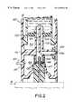
- FIG. 2is a schematic view of the sterility maintaining connection device.
- FIG. 3shows the system of FIG. 1 with a flexible wall dose and/or delivery container.
- FIG. 4shows a side view of the system of the invention with an inflexible wall dose and/or delivery container.
- a bulk containeris defined herein as any container that contains and has means to access a bulk or multipatient supply of a fluid that can be administered to an individual. That is, a bulk container contains a volume of fluid that is greater than a volume to be administered at one time or to one individual, hereinafter referred to as a unipatient supply.
- the bulk containermay contain variable volumes and may contain up to several liters of fluid. It may be manufactured of any biocompatible material, for example, glass or plastic and may be of any configuration, for example, having flexible or semi-flexible walls as in a plastic bag or having inflexible walls as in a glass bottle.
- a dose containeris defined herein as any container that contains a unipatient or single supply of a medical fluid to be administered.
- the dose containermay also be a delivery container for the fluid if the dose container is capable of both containing a unipatient supply of a medical fluid to be administered to an individual and also delivering the fluid to the individual without transfer of the fluid to a different container. That is, a dose container substantially contains or is filled with a unipatient supply of a medical fluid.
- a dose containermay be an ampule, bag, vial, capsule, etc. that holds a unipatient fluid supply.
- a delivery containermay be a syringe or bag that is capable of connecting, either directly or indirectly, to a patient to deliver the fluid.
- the dose and/or delivery containermay be made of any biocompatible material such as glass or plastic and may hold any unipatient volume. While the dose and/or delivery container may be of any shape or configuration and may contain compartments, the flexible wall delivery container in particular may contain channels, grooves, or other structures to retard, enhance, direct or otherwise affect fluid flow.
- a containeris disclosed in U.S. Pat. No. 5,779,693 entitled Flexible Plastic Container for the Containment and Delivery of Diagnostic Contrast Media and Parenteral Drug Formulations, which is expressly incorporated by reference herein in its entirety.
- a delivery containermay have flexible or semi-flexible walls such as a bag, or inflexible walls such as a syringe.
- a medical fluidis defined herein as any fluid or mixture of fluids that is administered to an individual for a therapeutic, diagnostic, physiologic and/or other medical purpose.
- the fluidis preferably sterile.
- examples of such fluidsinclude, but are not limited to, replenishing fluids such as normal saline, glucose, plasma, and/or electrolytes, diagnostic fluids such as contrast agents to enhance imaging by ultrasound (US), x-ray, computed tomography (CT), magnetic resonance imaging (MRI), and/or angiography, and therapeutic agents such as antibiotics and/or chemotherapeutic drugs.
- Fluids that are administered as mixtures of one or more diagnostic, therapeutic, physiologic and/or other agentsmay be mixed either prior to or during administration to an individual and may be contained in separate bulk containers in the system.
- the system 10 of the inventioncan be used to deliver any type of fluid 23 from a bulk source 14 to a dose and/or delivery container 16 .
- the system 10may also include delivering a fluid 23 from a dose and/or delivery container 16 directly or through a connector 20 to a patient (not shown).
- the system 10 of the inventionthus comprises the transfer of fluid 23 from a bulk source 14 to a dose and/or delivery container 16 as one component path 50 , the transfer of fluid 23 from a dose and/or delivery container 16 to a patient (not shown) as another component path 100 , and the total path 50 , 100 of transfer of fluid 23 from a bulk source 14 to a patient.
- the system 10includes administration of a unipatient supply of fluid 23 that has been transferred from a bulk container 14 to a patient, i.e., using both component paths 50 , 100 , as well as administration of fluid 23 from a prefilled delivery container 16 , such as a prefilled syringe or bag, i.e., using the component path 100 , to a patient.
- a prefilled delivery container 16such as a prefilled syringe or bag, i.e., using the component path 100
- the method of the total system 10 and/or its component paths 50 , 100may be automated.
- a plurality of bulk containers 14 , 14 a and connecting sites 66 , 66 aare contemplated.
- the bulk containers 14 , 14 amay contain the same or different fluids 23 . It may be desirable for the bulk containers 14 , 14 a to contain the same fluid 23 so that depletion of a first bulk container 14 would allow fluid 23 to be drawn from the second bulk container 14 a , thus not interrupting the process of fluid transfer. Alternatively, it may be desirable for the bulk containers 14 , 14 a to contain different fluids 23 to allow the same patient to receive more than one fluid 23 from a bulk source 14 , 14 a .
- An example of the later embodimentis a first bulk container 14 containing a contrast fluid and a second bulk container 14 a containing saline to allow a patency check of a patient's vessel with saline.
- Salinemay be drawn from bulk container 14 a prior to administration of the contrast fluid from bulk container 14 , and upon completion of an imaging procedure to flush the patient's vessel.
- the fluid 23 in the bulk container 14is accessible to the system 10 through a connecting site 66 .
- the connecting site 66may be integral with the bulk container 14 , as shown in phantom. Alternatively, the connecting site 66 may be separated from and connected to the bulk container 14 by a connector 48 .
- the bulk container 14 , 14 amay be sealed with a closure system 26 , typically either an elastomeric stopper secured with a crimped metal seal that acts as a septum or a luer-type connection port that maintains sterility of the contained fluid 23 but allows access to the fluid 23 .
- the bulk container 14 , 14 amay be placed in a holder 12 , 12 a for support, to facilitate its use, and/or to assist in removal of the maximal volume of fluid 23 such as where the bulk container 14 , 14 a is inverted in the holder 12 , 12 a.
- the bulk container 14 , 14 ais positioned to allow the contained fluid 23 to be accessible at a connecting site 66 , 66 a which may be a septum 67 , 67 a .
- the system 10may be configured with the connecting site 66 , 66 a integral with the bulk container 14 , 14 a , or separated from the bulk container 14 , 14 a and operably connected using tubing or other types of connectors 48 , 48 a . In the latter embodiment, a new sterile connector 48 , 48 a is attached at the connecting site 66 , 66 a upon installation of the new bulk container 14 , 14 a .
- the connector 48 , 48 afacilitates a single puncture of the closure system 26 on the bulk container 14 , 14 a to establish a sterile path of fluid 23 .
- the connector 48 , 48 amay also provide a secondary linkage point that permits multiple connections and disconnections to or from the bulk container 14 , 14 a.
- the connector 48remains attached to the bulk container 14 until the fluid 23 in the bulk container 14 is substantially depleted. At that time, or upon attainment of a preset level of fluid 23 in the first bulk container 14 .
- the operatively attached connector line 18 to the dose and/or delivery container 16disconnects at connecting site 66 and reconnects at connecting site 66 a , operably connecting bulk container 14 a by connector 48 a , to access the fluid 23 contained in the second bulk container 14 a .
- the fluid-depleted first bulk container 14is removed from the system 10 and is replaced with a third new container 14 b without interrupting the access of fluid 23 from bulk container 14 a at connecting site 66 a.
- the connecting site 66 , 66 ais maintained sterile using one or more of several methods.
- a sterility-maintaining shielding device 49that both shields and provides a sterilant to the connecting site 66 may be used.
- the device 49encloses the connecting site 66 with a first compartment 102 and second compartment 104 , the first compartment 102 enclosing a fluid channel 106 providing flow of fluid 23 from the bulk container 14 to the connecting site 66 , and a second compartment 104 providing a flow of fluid 23 from the connecting site 66 to a dose and/or delivery container 16 .
- the device 49provides a sterilant to the connecting site 66 .
- the sterilantmay be, for example, a flow of filtered air, a chemical sterilant, or a source of radiation.
- the device 49may be of any biocompatible material and may be a molded article such as an injection molded piece of plastic or rubber. It may connect in an area adjacent the connecting site 66 either directly or by mating adaptors, known to one skilled in the art.
- the device 49has two compartments 102 , 104 .
- the access means to the bulk container 14are fitted to the device 49 at a connector site 112 , closing the first compartment 102 .
- the bulk container 14may be engaged in the connector site 112 in a number of ways.
- there may be a snap-fit arrangementin which, during insertion, the bulk container 14 forces a wall of the connector site 112 to expand and, when the bulk container 14 is fully engaged, the wall snaps back into its static position.
- Still another exampleis a connector site 112 that is made of a deformable material such as rubber. The bulk container 14 , during insertion, could expand the walls of the connector site 112 with the walls remaining in a deformed position while the bulk container 14 was engaged.
- Other attachment devicescould also be used.
- the second compartment 104houses the connecting site 66 and also provides sterilant.
- the first 102 and second 104 compartmentsmay be separated by a rigid membrane 116 which supports an engaging projection 118 and a receiving projection 120 .
- the engaging projection 118penetrates the bulk container 14 and provides a channel 106 for flow of fluid 23 from the bulk container 14 to the connecting site 66 .
- engaging projection 118has a tip that is sufficiently sharp to pierce a septum 124 of the bulk container.
- Another method by which the engaging projection 118 could engage the bulk container 14are threads on the projection 118 and corresponding threads on the container 14 . Yet another means would be a snap fit between the container 14 and the projection 118 .
- the fluid channel 106provides the pathway for flow of fluid 23 from the bulk container 14 through the connecting site 66 and into the dose and/or delivery container 16 .
- the axis of the receiving projection 120is aligned with the axis of the engaging projection 118 to provide a straight fluid flow pathway.
- the channel 126contains a filter 128 and provides access to normal atmospheric pressure, allowing fluid 23 to be drawn out of the bulk container 14 .
- This access channel 126transverses the interiors of the engaging projection 118 and the rigid membrane 116 .
- the second compartment 104terminates in a door 130 or other means that provides controlled access to the septum 67 of the connecting site 66 .
- the door 130shields the receiving projection 120 from the environment when the dose and/or delivery container 16 is not operatively connected for filling.
- the door 130opens inwardly to the second compartment 104 upon engagement of the dose and/or delivery container 16 or its connecting line 18 , and retracts to a closed position when not so engaged.
- the door 130does not create a total seal; however, it generally seals the second compartment 104 when not contacting the receiving projection 120 .
- the shielding device 49allows the connecting site 66 access to a sterilant as previously described.
- the second compartment 104has a conduit 69 in its wall located to provide a sterilant to the connecting site 66 , particularly the portion of the connecting site 66 that is engaged upon connection in the system 10 .
- the connecting site 66may be operatively connected to a stream of filtered air 80 such as HEPA-filtered air forced into the second compartment 104 from a source (not shown).
- the flow of air 80is oriented so that it provides a unidirectional non-recirculating flow from its source, across the septum 67 or other access means at the connecting site 66 , and out of the second compartment 104 through the door 130 .
- the connecting site 66is exposed to a clean-room type of environment when fluid 23 from a bulk container 14 is operably accessible at the connecting site 66 .
- the flow of air 80 in the second compartment 104may be halted to decrease or conserve the supply of filtered air 80 .
- the second compartment 104also prevents or minimizes an operator from making contact with the connecting site 66 when operating the system 10 or manually changing the bulk container 14 .
- the positive outward flow of air 80prevents egress of contamination any time that the bulk supply 14 is removed from the system 10 .
- the conduit 69may alternatively provide the connecting site 66 access to a chemical sterilant.
- the chemical sterilantmay be a peroxide such as hydrogen peroxide or other chemical sterilant known in the art.
- the source of sterilantmay be located outside of the compartment 104 and directed into the compartment 104 by, for example, an aerosol or stream. Alternatively, the source of sterilant may be located within the compartment 104 .
- Still another method to maintain a sterile connecting site 66is by directing radiation from a source into the second compartment 104 and directed to irradiate the connecting site 66 .
- a radiation sourcesuch as a source of ultraviolet radiation at a wavelength of less than 400 nm is positioned to direct radiation to the connecting site 66 .
- the radiation sourcemay be positioned within the compartment 104 or may be positioned outside of the compartment 104 if the radiation can penetrate the compartment 104 to irradiate the connecting site 66 .
- the system 10contains a sensor 71 that will either alert the operator that the bulk container 14 has a predetermined volume of fluid 23 remaining, and/or disengage access to the connecting site 66 of a first bulk container 14 and engage the connecting site 66 a of the second bulk container 14 a .
- the sensor 71may be activated using, for example, optical, electronic or other means.
- the system 10may automatically engage a fresh bulk container 14 a without disruption of the transfer sequence of fluid 23 into the dose and/or delivery container 16 . In this way, the entire volume of fluid 23 from each bulk container 14 , 14 a may be utilized, which minimizes waste of fluid 23 .
- the system 10contains one or more air detection sensors 73 to facilitate bubble detection and/or removal along a fluid path, as described in U.S. Pat. No. 5,868,710 entitled Medical Fluid Injector which is expressly incorporated by reference herein in its entirety.
- the air detection sensors 73may be positioned anywhere along the fluid path, but are most helpful if located at least at points of fluid transfer, such as at a connecting site 66 , at entry and exit ports into and out of a dose and/or delivery container 16 , etc. Briefly, the sensors 73 detect the diffraction of light at an air/fluid or air/solid boundary, the air causing light rays to deviate substantially from their normal path.
- the sensor 73is thus light-sensitive and produces a signal indicating failure to receive light due to the presence of air.
- the system 10may contain a prime or flush mechanism to remove the air bubbles and/or may not engage until an operator has taken steps to remove the air bubbles.
- the fluid 23 infused into a patient at the desired timeis thus free of air bubbles.
- the delivery container 16has at least one flexible or semi-flexible wall 29 and is hereinafter referred to as a flexible wall container 27 .
- a flexible wall container 27An example of this type of delivery container 16 is a bag 28 , such as a typical intravenous fluid bag 28 .
- other deformable delivery containers 16may also be used, including compartmentalized strips or blister packages.
- Multiple compartments, such as those made by heat sealing, layering sheets, molding separate reservoirs, etc.may contain multiple medical fluids. The multiple compartments may be joined to a patient line 20 by valving, Y-connectors, piercing, unclamping, crushing or snapping.
- the delivery container 16 in this embodimentmay have an external rigid sleeve and port with a flexible inner bag similar to some types of baby bottles.
- the flexible wall container 27such as a bag 28 may be made of any type of material capable of withstanding sterilization and containing sterile fluid 23 , for example, resilient plastic that retains a specific form, plastic that completely collapses, etc.
- a flexible wall container 27 that is prefilled with fluid 23may be used.
- an empty flexible wall container 27may be filled with fluid 23 from a bulk container 14 as previously described.
- fluid 23is delivered from the flexible wall container 27 to the patient line 20 by providing pressure to at least one flexible wall 29 .
- Pressuremay be applied directly to the at least one flexible wall 29 of the container 27 , or alternatively as shown, pressure may be applied indirectly to the at least one flexible wall 29 by applying pressure to a pressurizeable chamber 30 adjacent the at least one flexible wall 29 of the container 27 .
- Pressuremay be provided by, for example, hydraulic means, mechanical means, pneumatic means, etc. from a source 56 .
- the chamber 30may have a clamshell-type opening to house the container 27 , with at least one side 31 of the chamber 30 capable of applying a pressure.
- the position of the container 27 within the chamber 30may be located by a number of indices such as pins, nubs, ribs, holes, etc.
- One surface of the chamber 30may be transparent to allow the operator to view the container 27 housed therein.
- the container 27may be completely contacted by the pressurizeable chamber 30 or have only the flexible wall 29 adjacent the side 31 of the chamber 30 capable of applying a pressure.
- the flexible wall container 27may be fitted into the pressurizeable chamber 30 , covering the entrance by a molded-in fitting that interlocks with the walls of the chamber 30 .
- the container 27may be locked in place by turning a hard fitting on the chamber 30 .
- the fitting and openingmay be on the sides or the back of the container 27 .
- the container 27may have a patient connector 20 which may protrude through an opening in the chamber 30 .
- the pressurizeable chamber 30contains a membrane 52 on at least one surface that is capable of exerting a desired pressure on the flexible wall 29 of the container 27 .
- the membrane 52is made of a material that is capable of withstanding the desired pressure with which to deliver the fluid 23 .
- the fluid 23is a contrast agent to be administered to a patient in preparation for an imaging procedure
- the required pressuredepends upon the particular imaging procedure to be performed. Pressures may range from as low as about 100 pounds per square inch (psi) to a pressure of about 1200 psi that is used in angiography.
- psipounds per square inch
- a membrane 52 capable of withstanding the maximum pressure for any proceduremay be used.
- the pressurizeable chamber 30may include at least a partial frame or holder 60 to provide a rigid outer shape.
- the holder 60may provide a handle (not shown) for holding and manipulating the container 27 .
- the holder 60may provide locating features (not shown) for locating or translating the container 27 into a pressurizeable chamber 30 and/or for positioning the container 27 into or out of a position for injecting the contained fluid 23 .
- the holder 60may be made of any rigid material such as metal, plastic, plexiglass, or the like.
- the holder 60may be adapted to operably connect the membrane 52 with an external pressure source (not shown). In an alternative embodiment, pressure may be applied by manual or automated pressing, squeezing, rolling, and so on.
- the container 27need not meet exacting pressure tolerances in its manufacture.
- Such a dose and/or delivery container 16is less costly to manufacture than one which would have to withstand direct application of pressure. This also minimizes any chance of breaking the integrity of the container 27 , which would possibly compromise the sterility of the fluid 23 and/or cause leakage of fluid 23 from the container 27 .
- a bulk container 14 of fluid 23is operably connected to the system 10 . This may be accomplished by seating the bulk container 14 in a holder 12 so as to initiate a flow of fluid 23 from the bulk container 14 to a connecting site 66 , which may either be integral with the bulk container 14 or attached to the bulk container 14 with a connector 48 .
- a dose and/or delivery container 16 having a connector line 18is operable attached at connecting site 66 .
- the connector line 18may be fitted with luer-type connectors (not shown) for a secure but resealable seal, and is made of any standard hospital grade sterile tubing such as Tygon® tubing.
- the flow of fluid 23 into the delivery container 16 from the bulk container 14is initiated by any number of mechanisms, including gravity, vacuum, pressurization, pumping, squeezing, rolling, or other fluid displacement techniques.
- the container 27is irreversibly disconnected, either directly or through connector line 18 from connecting site 66 .
- Any subsequent attempt to operatively reconnect connector line 18 at connecting site 66is prevented by, for example, configuring connector line 18 with a breakaway or removable cannula (not shown) that must be removed before the patient connector line 20 can be applied. Access to connecting site 66 would require this cannula. Other methods to prevent reconnection are also possible.
- Flow of fluid 23 from the flexible wall container 27may then be initiated into a patient through patient connector line 20 . This may be performed immediately after filling and disconnecting the flexible wall container 27 from the bulk source 14 , or may be performed at a later time.
- a flexible wall container 27 that has been prefilled, either at the site of manufacture or manually by a technologist,may be used.
- the system 10 in usedelivers a medical fluid 23 to a patient in a conventional manner, as known to one skilled in the art.
- the delivery container 16contains at least one port 32 for connecting either directly or indirectly to a patient connector line 20 for administration of fluid 23 into a patient at an infusion site.
- the systemcontains a device to detect extravasation of the fluid 23 at the patient infusion site, which either prompts the operator for action and/or terminates the process.
- a deviceto detect extravasation of the fluid 23 at the patient infusion site, which either prompts the operator for action and/or terminates the process.
- Such a deviceis disclosed in WO 99/15074 based on U.S. patent application No. 60/059,749 entitled Optical Extravasation Detection Method and Apparatus, which is expressly incorporated by reference herein in its entirety.
- a flexible wall container 27such as a bag 28 may be of any shape, for example, round, oval, elliptical, rectangular, etc.
- the bag 28may assume many configurations, such as a bag 28 having channels or directed fluid paths as disclosed in U.S. Pat. No. 5,779,693 entitled Flexible Plastic Container for the Containment and Delivery of Diagnostic Contrast Media and Parenteral Drug Formulations, which is hereby incorporated by reference herein in its entirety.
- an equal pressuremay be applied to all surfaces of the fluid 23 , unlike a syringe in which only unidirectional pressure is typically applied to the fluid 23 contained therein.
- the bag 28may have integral graphics or textural features whose visual appearance changes upon contact of the wall 29 with fluid 23 , thereby visually indicating that fluid 23 is present in the bag 28 . While a bag 28 may be sterilized and reused, it is preferred to dispose of the bag 28 after each use. A bag 28 also requires less area for disposal, both because of its flexibility to be rolled or folded to further decrease its area, and also because it is collapsible upon removal of fluid 23 from its interior. The bag 28 may be collapsible by folding in on itself. The material, geometry and form of the bag 28 may have features such as pleated sides to minimize entrapment of fluid 23 as the bag 28 collapses.
- the bag 28has at least one port 32 for at least one connector line 18 , 20 .
- the port 32is used to attach the bag 28 by a connector line 18 to the connecting site 66 to transfer fluid 23 from a bulk source 14 . After transfer of the desired volume of fluid 23 into the bag 28 and disconnection of either the bag itself 28 or the connector 18 from connecting site 66 , the port 32 may be sealed. Alternatively, a patient connector line 20 may be attached at either the same port 32 or at a different port 32 a for allowing fluid transfer to an infusion site in a patient.
- the connector lines 18 , 20may already be pre-attached to the bag 28 or other delivery container 16 .
- the bag 28must necessarily have at least two ports 32 , 32 a .
- the lines 18 , 20may connect to the port 32 , 32 a in any standard manner known to one skilled in the art, for example with luer-type connectors (not shown).
- the desired volume of fluid 23may be administered to a patient either immediately upon filling of a delivery container 16 and disconnection of connector line 18 from the connecting site 66 , or at any time thereafter.
- the flexible wall delivery container 27may also be pre-filled with the desired fluid 23 and inserted into the system 10 without being filled from a bulk source 14 .
- the pre-filled delivery container 27may be purchased already containing fluid 23 , or may have been previously filled from a bulk source 14 utilizing the system 10 or by other means, or may have been previously filled from a dose container 16 .
- a delivery container 16 having inflexible wallssuch as a syringe 81 may be used.
- the syringe 81has an independent filling port 82 and a separate discharge port 84 .
- the filling port 82is a tube or cannula 86 that is integral with and is located at the proximal end of the syringe 81 . It contains a check valve 88 to permit only unidirectional flow of fluid 23 from the bulk source 14 into the syringe 81 .
- the filling port 82When the filling port 82 is coupled at the connection site 66 , either directly to bulk container 14 or through connector line 18 or through connector 48 , and the discharge port 84 is sealed, for example, by a removable cap or frangible tip member 85 , fluid 23 enters the tube or cannula 86 . Refraction of the piston 90 forces fluid 23 to flow from the bulk supply 14 from the cannula 86 into the syringe barrel 92 . After the desired volume of fluid 23 has been withdrawn from the bulk source 14 , the filling port 82 is disconnected or decoupled from the connection site 66 , thus preventing fluid 23 access from the bulk supply 14 to the syringe 81 .
- the cap or tip member 85is removed before connecting by either manual or automated means, the discharge port 84 of the syringe 81 to the patient connector line 20 .
- the syringe 81may be operated either manually or in a power injection system. Essentially all of the fluid 23 contained within the syringe 81 may be expelled.
- a delivery container 16 having inflexible walls such as a syringe 81has several limitations that are not encountered when using a flexible wall container 27 .
- One drawback with a syringe 81is the need for lubricant chemicals such as silicone to lubricate the moveable piston 90 .
- Another drawbackis the increased cost of a syringe 81 due at least in part to the stringent manufacturing tolerances and the lubricants required for a secure fit of component parts.
- Still other drawbacksare the lower shipping units per container due to the rigid structure as compared to a flexible wall container 27 , lower disposal volume per unit area, and the need for protective packaging to minimize potential damage to the rigid walls during transport.
- the volume of fluid 23 that is transferred from the bulk source 14 to a dose and/or delivery container 16is substantially the volume that is to be administered to a patient.
- the dose and/or delivery container 16is referred to herein as being filled with fluid 23 although the entire volume of the container 16 may not be occupied with the fluid 23 .
- the system 10may be configured either as a single unit or in modules.
- a modular systemmay encompass unit 50 of a fluid path between the bulk source 14 and a dose and/or delivery container 16 , or unit 100 of a fluid path between the dose and/or delivery container 16 and the patient line 20 .
- a modular systemmay be used, for example, if size and/or weight of a single unit is prohibitive.
- an operatoris prompted at the conclusion of a procedure on one patient by an operator interface system to enter patient- and procedure-specific parameters for a subsequent patient to be imaged. Determination of these parameters may be by various manual methods and/or computer implemented algorithms, as disclosed in U.S. Pat. No. 5,583,902 entitled Method of and Apparatus for Predicting Computed Tomography Contrast Enhancement, which is expressly incorporated by reference herein in its entirety. A variable number of patient specific parameters may be used in calculating the optimal volume of fluid 23 .
- Examplesinclude body mass, weight, volume of distribution, total plasma clearance, parameters of renal excretion such as glomerular filtration, tubular secretion, and tubular reabsorption, parameters of liver function such as enzyme and protein levels, and parameters of cardiac function such as blood flow and blood pressure, just to name a few.
- the system 10then automatically initiates transfer of the required volume of fluid 23 into the dose and/or delivery container 16 . If the bulk source 14 becomes depleted during the transfer, the system 10 automatically switches to a second bulk source 14 a by mechanically withdrawing connector line 18 from connecting site 66 and reconnecting to the connecting site 66 a for bulk supply 14 a .
- the connecting and reconnectingmay be accomplished using an automated or manual method.
- Transfer of fluid 23resumes until the desired volume entered the dose and/or delivery container 16 .
- the system 10continuously monitors the path of fluid 23 for the presence of air using sensors 73 and automatically purges the system 10 and/or prompts the operator.
- an interface systemmay alert the operator that the fluid 23 is ready for administration.
- the sensors 73actively monitor the path of fluid 23 for air bubbles and automatically shuts down the injection and/or alerts the operator if bubbles are detected.
- the system 10may be configured so that system, procedure and/or patient information may be communicated to a network.
- the bulk container 14may have an integral magnetic strip 74 containing information about the bulk container 14 and its contents such as identity, lot number, expiration date, brand, manufacturer, clinical indications, time of use and number of uses.
- the magnetic stripmay be written to by the delivery container 16 .
- the magnetic stripmay also contain information intended to be communicated from the manufacturer to the clinicians or technologists using the product.
- the encoded informationmay be written to or read by a variety of means such as optical etching or radiofrequency.
- the dose and/or delivery container 16may also contain a similar magnetic strip containing the above-described written or read information.
- the system 10may be linked to a purchasing network.
- the bulk container 14 and/or dose and/or delivery container 16may contain an identifier 76 such as a magnetic strip 74 that is readable by a computerized information system, such as an inventory tracking system used by a purchasing department.
- the identifier 76may be a sticker containing, for example, a bar code, a radiofrequency source, or a micro chip, and may contain a variety of information such as product name, source, concentration, lot number, expiration date, whether the package had been previously used, etc.
- the computerized information systemmay track the volume of fluid 23 either removed and/or remaining in the bulk source 14 , 14 a , and/or the number of bulk source packages 14 , 14 a placed in or removed from holders 12 , 12 a . Using this information, a purchasing system may quickly update its orders for a new supply of bulk source packages 14 , 14 a to maintain a desired level of inventory.
- the inventionhas numerous advantages, the following being illustrative and not limiting examples.
- One advantage of the inventionis that there is a substantially reduced risk of patient and fluid 23 contamination, yielding greater safety in administering medical fluids to patients.
- Another advantageis that standard size bulk contrast supply packages 14 , 14 a may be used, thereby eliminating numerous package sizes and separate dose and/or delivery container 16 filling steps.
- Still another advantageis that the invention allows optimization of the volume of fluid 23 such as contrast agent injected into each patient for desired image quality and patient safety.
- Yet another advantageis the cost and time efficiency from the system 10 as compared to individual components.
Landscapes
- Health & Medical Sciences (AREA)
- Public Health (AREA)
- Life Sciences & Earth Sciences (AREA)
- Veterinary Medicine (AREA)
- Animal Behavior & Ethology (AREA)
- Heart & Thoracic Surgery (AREA)
- General Health & Medical Sciences (AREA)
- Hematology (AREA)
- Engineering & Computer Science (AREA)
- Anesthesiology (AREA)
- Biomedical Technology (AREA)
- Vascular Medicine (AREA)
- Epidemiology (AREA)
- Pulmonology (AREA)
- Nutrition Science (AREA)
- Chemical & Material Sciences (AREA)
- Medicinal Chemistry (AREA)
- Pharmacology & Pharmacy (AREA)
- Infusion, Injection, And Reservoir Apparatuses (AREA)
- Apparatus For Disinfection Or Sterilisation (AREA)
Abstract
Description
Claims (17)
Priority Applications (8)
| Application Number | Priority Date | Filing Date | Title |
|---|---|---|---|
| US09/353,521US6355024B1 (en) | 1999-07-14 | 1999-07-14 | Medical fluid delivery system |
| EP06009588.2AEP1685864B1 (en) | 1999-07-14 | 2000-07-14 | Method and connector for maintaining sterility of a medical fluid |
| EP00948679AEP1194178A2 (en) | 1999-07-14 | 2000-07-14 | Medical fluid delivery system |
| ES06009588.2TES2565823T3 (en) | 1999-07-14 | 2000-07-14 | Method and connector to maintain the sterility of a medical fluid |
| PCT/US2000/019275WO2001003757A2 (en) | 1999-07-14 | 2000-07-14 | Medical fluid delivery system |
| EP07003864AEP1810707A1 (en) | 1999-07-14 | 2000-07-14 | Medical fluid delivery system |
| JP2001509229AJP2003504124A (en) | 1999-07-14 | 2000-07-14 | Medical fluid supply device |
| US09/788,791US6623455B2 (en) | 1999-07-14 | 2001-02-20 | Medical fluid delivery system |
Applications Claiming Priority (3)
| Application Number | Priority Date | Filing Date | Title |
|---|---|---|---|
| US35356399A | 1999-07-14 | 1999-07-14 | |
| US09/353,217US6468261B1 (en) | 1999-07-14 | 1999-07-14 | Medical fluid delivery system |
| US09/353,521US6355024B1 (en) | 1999-07-14 | 1999-07-14 | Medical fluid delivery system |
Publications (1)
| Publication Number | Publication Date |
|---|---|
| US6355024B1true US6355024B1 (en) | 2002-03-12 |
Family
ID=27408102
Family Applications (2)
| Application Number | Title | Priority Date | Filing Date |
|---|---|---|---|
| US09/353,521Expired - LifetimeUS6355024B1 (en) | 1999-07-14 | 1999-07-14 | Medical fluid delivery system |
| US09/788,791Expired - LifetimeUS6623455B2 (en) | 1999-07-14 | 2001-02-20 | Medical fluid delivery system |
Family Applications After (1)
| Application Number | Title | Priority Date | Filing Date |
|---|---|---|---|
| US09/788,791Expired - LifetimeUS6623455B2 (en) | 1999-07-14 | 2001-02-20 | Medical fluid delivery system |
Country Status (5)
| Country | Link |
|---|---|
| US (2) | US6355024B1 (en) |
| EP (3) | EP1685864B1 (en) |
| JP (1) | JP2003504124A (en) |
| ES (1) | ES2565823T3 (en) |
| WO (1) | WO2001003757A2 (en) |
Cited By (39)
| Publication number | Priority date | Publication date | Assignee | Title |
|---|---|---|---|---|
| US20020087362A1 (en)* | 2001-01-02 | 2002-07-04 | Cobb David M. | Systems and methods for tracking administration of medical products |
| US20030047616A1 (en)* | 2001-03-30 | 2003-03-13 | Mase Joseph C. | Coding symbology and a method for printing same |
| US20030055685A1 (en)* | 2001-09-19 | 2003-03-20 | Safety Syringes, Inc. | Systems and methods for monitoring administration of medical products |
| US20030164401A1 (en)* | 2002-02-26 | 2003-09-04 | Safety Syringes, Inc. | Systems and methods for tracking pharmaceuticals within a facility |
| US6679300B1 (en)* | 2002-01-14 | 2004-01-20 | Thermogenesis Corp. | Biological adhesive loading station and method |
| US20040046020A1 (en)* | 2002-02-26 | 2004-03-11 | Safety Syringes, Inc. | Pharmaceutical tracking |
| US20040051368A1 (en)* | 2002-09-17 | 2004-03-18 | Jimmy Caputo | Systems and methods for programming pumps |
| US20050088306A1 (en)* | 2002-02-26 | 2005-04-28 | Safety Syringes, Inc. | Systems and methods for tracking pharmaceuticals within a facility |
| US20060133966A1 (en)* | 2001-12-31 | 2006-06-22 | Digianfilippo Aleandro | Transfer set for use with a pharmaceutical compounder |
| US20060259195A1 (en)* | 2004-12-22 | 2006-11-16 | Eliuk Walter W | Automated pharmacy admixture system (APAS) |
| US20070265230A1 (en)* | 2006-05-11 | 2007-11-15 | Benny Rousso | Radiopharmaceuticals For Diagnosis And Therapy |
| US20080001090A1 (en)* | 2006-06-28 | 2008-01-03 | Spectrum Dynamics Llc | Imaging Techniques For Reducing Blind Spots |
| US20080114328A1 (en)* | 2006-11-09 | 2008-05-15 | Intelligent Hospital Systems Ltd. | Control of Fluid Transfer Operations |
| US20080125721A1 (en)* | 2006-07-12 | 2008-05-29 | Mobius Therapeutics, Inc. | Apparatus and method for reconstituting a pharmaceutical and preparing the reconstituted pharmaceutical for transient application |
| US20080195249A1 (en)* | 2004-11-09 | 2008-08-14 | Spectrum Dynamics Llc | Radiopharmaceutical dispensing, administration, and imaging |
| US20080199353A1 (en)* | 2005-12-22 | 2008-08-21 | Intelligent Hospital Systems Ltd. | Ultraviolet Sanitization In Pharmacy Environments |
| US20090018596A1 (en)* | 2007-05-15 | 2009-01-15 | Cvrx, Inc. | Baroreflex activation therapy device with pacing cardiac electrical signal detection capability |
| US20090057257A1 (en)* | 2007-09-04 | 2009-03-05 | Pamela Wong Marcus | Protective sleeves for containers |
| US20090067973A1 (en)* | 2007-09-12 | 2009-03-12 | Intelligent Hospital Systems Ltd. | Gripper Device |
| US20090126825A1 (en)* | 2007-11-16 | 2009-05-21 | Intelligent Hospital Systems Ltd. | Method and Apparatus for Automated Fluid Transfer Operations |
| US7610115B2 (en) | 2004-12-22 | 2009-10-27 | Intelligent Hospital Systems Ltd. | Automated pharmacy admixture system (APAS) |
| US20100174180A1 (en)* | 2004-11-09 | 2010-07-08 | Benny Rousso | Imaging System Customization Using Data From Radiopharmaceutical-Associated Data Carrier |
| US7777130B2 (en) | 2007-06-18 | 2010-08-17 | Vivant Medical, Inc. | Microwave cable cooling |
| US20100241270A1 (en)* | 2009-03-18 | 2010-09-23 | Intelligent Hospital Systems Ltd. | Automated Pharmacy Admixture System |
| US20100288719A1 (en)* | 2009-05-13 | 2010-11-18 | Derek Berton Rund | Protective bottle sling |
| US20110022047A1 (en)* | 2009-07-23 | 2011-01-27 | Tyco Healthcare Group Lp | Active Cooling System and Apparatus for Controlling Temperature of a Fluid used During Treatment of Biological Tissue |
| US20110071582A1 (en)* | 2009-09-24 | 2011-03-24 | Vivant Medical, Inc. | Optical Detection of Interrupted Fluid Flow to Ablation Probe |
| US20110123073A1 (en)* | 2009-11-24 | 2011-05-26 | Greg Gustafson | Mammography statistical diagnostic profiler and prediction system |
| US20110137132A1 (en)* | 2009-11-24 | 2011-06-09 | Gustafson Gregory A | Mammography Information System |
| US20120029464A1 (en)* | 2008-10-15 | 2012-02-02 | Novo Nordisk Healthcare Ag | System for reconstitution of a powdered drug |
| US20140228783A1 (en)* | 2011-09-19 | 2014-08-14 | Daniel L. Kraft | Eye drop dispenser |
| US8945051B2 (en) | 2009-07-24 | 2015-02-03 | Bayer Medical Care Inc. | Multi-fluid medical injector system and methods of operation |
| US20150224248A1 (en)* | 2012-06-13 | 2015-08-13 | Medex | Assembly for injecting a viscous liquid product |
| US9205075B2 (en) | 2006-07-12 | 2015-12-08 | Mobius Therapeutics, Llc | Apparatus and method for reconstituting a pharmaceutical and preparing the reconstituted pharmaceutical for transient application |
| US9539241B2 (en) | 2006-07-12 | 2017-01-10 | Mobius Therapeutics, Llc | Apparatus and method for reconstituting a pharmaceutical and preparing the reconstituted pharmaceutical for transient application |
| US9662439B2 (en) | 2012-06-13 | 2017-05-30 | Medex | Controller for the automatic control of an injection device |
| US9714650B2 (en) | 2013-06-11 | 2017-07-25 | Matthew G. Morris, Jr. | Pumping system |
| US10869961B2 (en) | 2017-11-06 | 2020-12-22 | Sorrel Medical Ltd. | Local disinfection for drug delivery system |
| US10869960B2 (en) | 2017-11-06 | 2020-12-22 | Sorrel Medical Ltd | Local disinfection for prefilled drug delivery system |
Families Citing this family (75)
| Publication number | Priority date | Publication date | Assignee | Title |
|---|---|---|---|---|
| CA2168554A1 (en)* | 1993-08-11 | 1995-02-16 | Thomas John Berrigan | Implantable drug delivery means |
| SE523272C2 (en)* | 1999-11-15 | 2004-04-06 | Aneo Ab | System for intravenous anesthesia for the control of a drug delivery to a patient |
| US7308300B2 (en)* | 2001-05-30 | 2007-12-11 | Acist Medical Systems, Inc. | Medical injection system |
| WO2003026558A2 (en)* | 2001-09-24 | 2003-04-03 | Scott Laboratories, Inc. | Methods and apparatuses for assuring quality and safety of drug administration and medical products and kits |
| US6758835B2 (en) | 2002-05-01 | 2004-07-06 | Medtg, Llc | Disposable needle assembly having sensors formed therein permitting the simultaneous drawing and administering of fluids and method of forming the same |
| US7753085B2 (en)* | 2002-12-03 | 2010-07-13 | Forhealth Technologies, Inc. | Automated drug preparation apparatus including automated drug reconstitution |
| US10688021B2 (en) | 2002-12-03 | 2020-06-23 | Baxter Corporation Englewood | Automated drug preparation apparatus including automated drug reconstitution |
| US7117902B2 (en)* | 2002-12-03 | 2006-10-10 | Forhealth Technologies, Inc. | Automated means of storing, dispensing and orienting injectable drug vials for a robotic application |
| NZ523300A (en)* | 2002-12-20 | 2005-12-23 | Impian Technologies Ltd | Peristaltic pump head and tube holder |
| IL157981A (en) | 2003-09-17 | 2014-01-30 | Elcam Medical Agricultural Cooperative Ass Ltd | Auto-injector |
| IL157984A (en) | 2003-09-17 | 2015-02-26 | Dali Medical Devices Ltd | Autoneedle |
| JP2005131007A (en)* | 2003-10-29 | 2005-05-26 | Nemoto Kyorindo:Kk | Medical fluid injection system |
| DE102004003371B4 (en)* | 2004-01-22 | 2012-08-30 | Siemens Ag | Method for operating a computer tomograph and an injector, and device with a computer tomograph and an injector |
| US7771389B2 (en)* | 2004-02-17 | 2010-08-10 | Mallinckrodt Inc. | Injector auto purge |
| US8440139B2 (en)* | 2004-03-04 | 2013-05-14 | Ethican, Inc. | Method of delivering liquid sterilant to a sterilizer |
| IL160891A0 (en) | 2004-03-16 | 2004-08-31 | Auto-mix needle | |
| US7163031B2 (en)* | 2004-06-15 | 2007-01-16 | Mallinckrodt Inc. | Automated dispensing system and associated method of use |
| JP4850700B2 (en)* | 2004-06-21 | 2012-01-11 | 株式会社根本杏林堂 | Chemical injection system |
| US7146781B1 (en) | 2004-12-06 | 2006-12-12 | Nathan Albert Cole | Apparatus and method for insertion of material into uncontaminated containers |
| US20060211989A1 (en)* | 2005-03-04 | 2006-09-21 | Rhinehart Edward J | Fluid delivery systems, devices and methods for delivery of fluids |
| WO2006122180A2 (en)* | 2005-05-10 | 2006-11-16 | Par Technologies Llc | Disposable fluid container with integrated pump motive assembly |
| WO2007079305A2 (en)* | 2005-12-02 | 2007-07-12 | Baxa Corporation | Improved automated medical liquid filling system and method |
| US7963945B2 (en)* | 2005-12-14 | 2011-06-21 | Hewlett-Packard Development Company, L.P. | Replaceable supplies for IV fluid delivery systems |
| US7681606B2 (en)* | 2006-08-10 | 2010-03-23 | Fht, Inc. | Automated system and process for filling drug delivery devices of multiple sizes |
| US8151835B2 (en)* | 2006-08-23 | 2012-04-10 | Fht, Inc. | Automated drug delivery bag filling system |
| CN101516434B (en)* | 2006-10-18 | 2011-09-07 | 泰尔茂株式会社 | Medical apparatus |
| US7900658B2 (en) | 2006-10-20 | 2011-03-08 | Fht, Inc. | Automated drug preparation apparatus including drug vial handling, venting, cannula positioning functionality |
| US20080169044A1 (en) | 2006-10-20 | 2008-07-17 | Forhealth Technologies, Inc. | Automated drug preparation apparatus including syringe loading, preparation and filling |
| US7814731B2 (en) | 2006-10-20 | 2010-10-19 | Forhealth Technologies, Inc. | Automated drug preparation apparatus including a bluetooth communications network |
| US7913720B2 (en)* | 2006-10-31 | 2011-03-29 | Fht, Inc. | Automated drug preparation apparatus including serial dilution functionality |
| US20090124996A1 (en)* | 2006-11-03 | 2009-05-14 | Scott Heneveld | Apparatus and methods for injecting high viscosity dermal fillers |
| ES2391719T3 (en)* | 2007-11-19 | 2012-11-29 | Mallinckrodt Llc | Fluid delivery system with multi-dose fluid source |
| WO2009076429A2 (en) | 2007-12-10 | 2009-06-18 | Medrad, Inc. | Continuous fluid delivery system and method |
| US8002753B2 (en) | 2007-12-21 | 2011-08-23 | Nordson Corporation | Self-contained pressurized injection device |
| US8431074B2 (en)* | 2008-07-29 | 2013-04-30 | Mallinckrodt Llc | Ultraviolet tubing and tip sterilizer |
| DK2198778T3 (en)* | 2008-12-19 | 2013-10-14 | Hoffmann La Roche | Infusion apparatus with impedance measurement |
| US20100203853A1 (en)* | 2009-02-11 | 2010-08-12 | Sanyo Electric Co., Ltd. | Usage frequency determining device and transmitting device |
| WO2010117919A1 (en)* | 2009-04-08 | 2010-10-14 | Mallinckrodt Inc. | Vacuum assist syringe filling |
| US20100286650A1 (en)* | 2009-05-07 | 2010-11-11 | Alan Fitzgerald | Medical Fluid Container |
| ES3004613T3 (en)* | 2009-07-29 | 2025-03-12 | Icu Medical Inc | Fluid transfer devices |
| DK2319477T3 (en)* | 2009-11-06 | 2012-04-23 | Hoffmann La Roche | Device for filling a flexible storage container in a vacuum chamber |
| KR101798671B1 (en)* | 2009-11-27 | 2017-11-16 | 바이엘 인텔렉쳐 프로퍼티 게엠베하 | Injector system |
| US8197438B2 (en)* | 2009-12-23 | 2012-06-12 | Roche Diagnostics Operations, Inc. | Medicinal fluid delivery systems and methods for priming the same |
| CN102939120B (en) | 2010-06-04 | 2016-12-07 | 拜耳医药保健有限责任公司 | Systems and methods for planning and monitoring the use of multiple doses of radiopharmaceuticals on radiopharmaceutical syringes |
| US8814829B2 (en) | 2010-08-12 | 2014-08-26 | Baxter International Inc. | Drug delivery device for fluid restricted patients |
| US8353869B2 (en) | 2010-11-02 | 2013-01-15 | Baxa Corporation | Anti-tampering apparatus and method for drug delivery devices |
| US11338081B2 (en)* | 2011-04-04 | 2022-05-24 | Jihad Mustapha | Fluid mixing device |
| US9078809B2 (en)* | 2011-06-16 | 2015-07-14 | Crisi Medical Systems, Inc. | Medication dose preparation and transfer system |
| JP2014527881A (en) | 2011-09-21 | 2014-10-23 | ベイヤー メディカル ケア インク. | Continuous multi-fluid pump device, drive and actuation system and method |
| KR102145639B1 (en) | 2011-12-22 | 2020-08-19 | 아이씨유 메디칼 인코퍼레이티드 | Fluid transfer devices and methods of use |
| KR101757151B1 (en) | 2012-01-17 | 2017-07-12 | 닥터.피와이 인스터튜트, 엘엘씨 | Multiple dose syringe and method |
| ES2376436B1 (en) | 2012-01-31 | 2012-11-19 | Grifols, S.A. | CONTAINER OF PRODUCTS DERIVED FROM THE BLOOD. |
| DK2938369T3 (en) | 2012-12-31 | 2018-08-06 | Medtg Llc | INFUSION AND BLOOD COLLECTION DEVICE |
| CN105209998B (en)* | 2013-03-15 | 2017-11-14 | 百特恩格伍德公司 | With the system and method for premixed solution formulated |
| ES2805051T3 (en) | 2013-11-25 | 2021-02-10 | Icu Medical Inc | Procedures and system for filling I.V. bags with therapeutic liquid |
| US9399216B2 (en) | 2013-12-30 | 2016-07-26 | General Electric Company | Fluid transport in microfluidic applications with sensors for detecting fluid presence and pressure |
| US10076751B2 (en) | 2013-12-30 | 2018-09-18 | General Electric Company | Systems and methods for reagent storage |
| EP3126050B1 (en)* | 2014-04-02 | 2018-09-26 | Merck Patent GmbH | Fluid transfer device and process of aseptically transferring a fluid |
| US10507319B2 (en) | 2015-01-09 | 2019-12-17 | Bayer Healthcare Llc | Multiple fluid delivery system with multi-use disposable set and features thereof |
| CN104666081A (en)* | 2015-03-19 | 2015-06-03 | 崇州君健塑胶有限公司 | Accessory for infusion bag |
| US11357966B2 (en) | 2015-04-23 | 2022-06-14 | B. Braun Medical Inc. | Compounding device, system, kit, software, and method |
| MY206362A (en) | 2015-06-19 | 2024-12-12 | Takeda Pharmaceuticals Co | Pooling device for single or multiple containers |
| EP4534065A3 (en) | 2015-12-04 | 2025-06-04 | ICU Medical, Inc. | Systems methods and components for transferring medical fluids |
| WO2017100621A1 (en) | 2015-12-11 | 2017-06-15 | Nxstage Medical, Inc. | Fluid line connector devices methods and systems |
| USD851745S1 (en) | 2016-07-19 | 2019-06-18 | Icu Medical, Inc. | Medical fluid transfer system |
| EP3487468B1 (en) | 2016-07-25 | 2025-10-01 | ICU Medical, Inc. | Systems and components for trapping air bubbles in medical fluid transfer modules and systems |
| US10993878B2 (en)* | 2017-03-24 | 2021-05-04 | Carefusion 303, Inc. | Dual-lumen tubing for automatic drug compounder |
| GB201721463D0 (en) | 2017-12-20 | 2018-01-31 | Ge Healthcare As | Tailored dose of contrast agent |
| IT201800004116A1 (en)* | 2018-03-30 | 2019-09-30 | Adienne Pharma & Biotech Sa | Sterilized flexible packaging with pressure compensator for the dosed reconstitution of pharmaceutical or nutritional fluids that can be administered to a patient by infusion or injection. |
| CN113015510B (en) | 2018-10-03 | 2025-01-10 | 武田药品工业株式会社 | Packaging for multiple containers |
| WO2020072230A2 (en) | 2018-10-03 | 2020-04-09 | Baxalta GmbH | Pooling device for single or multiple medical containers |
| US11925786B2 (en)* | 2019-05-15 | 2024-03-12 | GE Precision Healthcare LLC | System and method for drawing a solution |
| EP4064989A4 (en) | 2019-11-26 | 2023-12-06 | Medtg LLC | Infusion and blood collection devices and methods |
| CN111265693A (en)* | 2020-04-02 | 2020-06-12 | 湖州众合孵化器有限公司 | Hang and spray formula degassing unit on a large scale in roof |
| US11590057B2 (en) | 2020-04-03 | 2023-02-28 | Icu Medical, Inc. | Systems, methods, and components for transferring medical fluids |
Citations (41)
| Publication number | Priority date | Publication date | Assignee | Title |
|---|---|---|---|---|
| US441238A (en) | 1890-11-25 | Syringe | ||
| US553234A (en) | 1896-01-21 | Philip finot | ||
| US1223243A (en) | 1916-06-15 | 1917-04-17 | Alfred N Bessesen | Syringe. |
| US1831668A (en) | 1928-04-28 | 1931-11-10 | Chris E Juhl | Syringe |
| US3051173A (en) | 1960-05-12 | 1962-08-28 | Alvin P Johnson | Veterinary hypodermic syringe |
| US3620650A (en) | 1969-12-05 | 1971-11-16 | Robert F Shaw | Gas-disabled liquid-pumping apparatus |
| US4433974A (en)* | 1981-06-17 | 1984-02-28 | Baxter Travenol Laboratories, Inc. | Mixing system for parenteral liquids |
| US4620845A (en)* | 1981-06-05 | 1986-11-04 | Popovich Robert P | Method of peritoneal dialysis involving ultraviolet radiation of dialysis apparatus |
| US4795429A (en)* | 1987-10-28 | 1989-01-03 | Feldstein Marvin A | Method and apparatus for use in the control of intravenous medication introduction |
| US4936829A (en)* | 1988-10-19 | 1990-06-26 | Baxter International Inc. | Drug delivery apparatus including beneficial agent chamber with chimney for a directed flow path |
| US5078691A (en) | 1990-03-01 | 1992-01-07 | Hamacher Edward N | Multiple-dose fluid delivery system and method |
| US5122121A (en) | 1990-08-30 | 1992-06-16 | E-Z-Em, Inc. | Safety needle assembly |
| US5188610A (en) | 1991-10-18 | 1993-02-23 | Vetrisystems, Inc. | Fluid dispensing apparatus |
| US5207642A (en)* | 1987-08-07 | 1993-05-04 | Baxter International Inc. | Closed multi-fluid delivery system and method |
| US5211638A (en) | 1988-01-25 | 1993-05-18 | Baxter International Inc. | Pre-slit injection site |
| US5328463A (en) | 1992-09-18 | 1994-07-12 | Namic U.S.A. Corporation | Contrast media and fluid introduction system |
| US5329976A (en)* | 1991-12-09 | 1994-07-19 | Habley Medical Technology Corporation | Syringe-filling and medication mixing dispenser |
| US5334170A (en) | 1993-07-14 | 1994-08-02 | Abbott Laboratories | Dye management system including an administration set with an in-line burette |
| US5336188A (en)* | 1989-06-16 | 1994-08-09 | Science Incorporated | Fluid delivery apparatus having a stored energy source |
| US5383859A (en) | 1992-02-06 | 1995-01-24 | Sewell, Jr.; Frank | Rotatable laparoscopic puncturing instrument |
| US5411499A (en) | 1988-01-25 | 1995-05-02 | Baxter International Inc. | Needleless vial access device |
| EP0650739A1 (en) | 1993-10-28 | 1995-05-03 | Medrad, Inc. | Total system for contrast delivery |
| US5450847A (en) | 1991-04-22 | 1995-09-19 | Schering Aktiengesellschaft | Process for making doses formulation of contrast media from concentrate |
| US5533978A (en) | 1994-11-07 | 1996-07-09 | Teirstein; Paul S. | Method and apparatus for uninterrupted delivery of radiographic dye |
| US5569208A (en) | 1995-08-01 | 1996-10-29 | Merit Medical Systems, Inc. | System for managing delivery of contrast media |
| US5569181A (en) | 1993-10-28 | 1996-10-29 | Medrad, Inc. | Sterility assurance for contrast delivery system |
| US5573515A (en) | 1995-04-20 | 1996-11-12 | Invasatec, Inc. | Self purging angiographic injector |
| US5583902A (en) | 1995-10-06 | 1996-12-10 | Bhb General Partnership | Method of and apparatus for predicting computed tomography contrast enhancement |
| US5665074A (en) | 1995-09-28 | 1997-09-09 | Liebel Flarsheim Company | Limited backflow reflux valve |
| US5728087A (en) | 1996-07-30 | 1998-03-17 | Bracco Diagnostics, Inc. | Universal flexible plastic container with multiple access ports of inverted Y shape configuration |
| US5728086A (en) | 1996-07-30 | 1998-03-17 | Bracco Diagnostics, Inc. | Universal flexible plastic container with multiple access ports |
| US5738671A (en) | 1996-07-30 | 1998-04-14 | Bracco Diagnostics Inc. | Flexible plastic container for the containment and delivery of diagnostic contrast media and parenteral drug formulations |
| US5772651A (en) | 1994-01-18 | 1998-06-30 | Dibra S.P.A. | Container for diagnostic contrast compositions |
| EP0852152A1 (en) | 1997-01-06 | 1998-07-08 | Medex | Medical liquid injection device |
| US5779693A (en) | 1996-07-30 | 1998-07-14 | Bracco Diagnostics, Inc. | Flexible plastic container for the containment and delivery of diagnostic contrast media and parenteral drug formulations |
| US5817082A (en) | 1996-11-08 | 1998-10-06 | Bracco Diagnostics Inc. | Medicament container closure with integral spike access means |
| US5840026A (en) | 1994-09-21 | 1998-11-24 | Medrad, Inc. | Patient specific dosing contrast delivery systems and methods |
| US5843037A (en) | 1993-10-28 | 1998-12-01 | Medrad Inc. | Multipatient fluid dispensing |
| US5868710A (en) | 1996-11-22 | 1999-02-09 | Liebel Flarsheim Company | Medical fluid injector |
| WO1999015074A1 (en) | 1997-09-23 | 1999-04-01 | Mallinckrodt Inc. | Optical extravasation detection method and apparatus |
| US5911252A (en)* | 1997-04-29 | 1999-06-15 | Cassel; Douglas | Automated syringe filling system for radiographic contrast agents and other injectable substances |
Family Cites Families (19)
| Publication number | Priority date | Publication date | Assignee | Title |
|---|---|---|---|---|
| GB486442A (en)* | 1936-12-02 | 1938-06-02 | Martin Constan Schwab | Improvements in apparatus for dispensing liquids for surgical injection and other purposes |
| US4133314A (en)* | 1976-12-06 | 1979-01-09 | American Hospital Supply Corporation | Extension transfer set |
| US4187890A (en)* | 1978-12-04 | 1980-02-12 | Mono-Med, Inc. | Filling apparatus for pharmaceuticals |
| US4253684A (en)* | 1979-05-14 | 1981-03-03 | Monsanto Company | Quick connect coupler with air shield |
| US4253501A (en)* | 1979-11-09 | 1981-03-03 | Ims Limited | Transfer system |
| US4432766A (en)* | 1981-07-29 | 1984-02-21 | Baxter Travenol Laboratories, Inc. | Conduit connectors having antiseptic application means |
| US4398909A (en)* | 1981-12-31 | 1983-08-16 | Portnoff Joel B | Unit dose applicator |
| US4754786A (en)* | 1986-09-05 | 1988-07-05 | Roderick Roberts | Sterile fluid storage and dispensing apparatus and method for filling same |
| US4883473A (en)* | 1987-04-29 | 1989-11-28 | Path | Single use injection device |
| JP3184831B2 (en)* | 1989-05-25 | 2001-07-09 | フレセニウス アーゲー | A device for simultaneous simultaneous administration of multiple infusions or drug solutions |
| US5304165A (en)* | 1991-12-09 | 1994-04-19 | Habley Medical Technology Corporation | Syringe-filling medication dispenser |
| US5334141A (en)* | 1992-06-26 | 1994-08-02 | Medrad, Inc. | Extravasation detection system and apparatus |
| US5395340A (en)* | 1993-03-15 | 1995-03-07 | Lee; Tzium-Shou | Infusion pump and a method for infusing patients using same |
| US5348539A (en)* | 1993-06-29 | 1994-09-20 | Glenn Herskowitz | Infusion pump for use with prepackaged IV bags |
| US5609575A (en)* | 1994-04-11 | 1997-03-11 | Graseby Medical Limited | Infusion pump and method with dose-rate calculation |
| US5697918A (en)* | 1995-02-23 | 1997-12-16 | Ultradent Products, Inc. | Systems for storing and dispensing dental compositions |
| US5772635A (en)* | 1995-05-15 | 1998-06-30 | Alaris Medical Systems, Inc. | Automated infusion system with dose rate calculator |
| KR19990028687A (en)* | 1995-07-11 | 1999-04-15 | 앙드레 롤랜드 | Through pin for injection device |
| ATE216605T1 (en)* | 1995-08-25 | 2002-05-15 | Debiotech Sa | DEVICE FOR CONTINUOUS INJECTION |
- 1999
- 1999-07-14USUS09/353,521patent/US6355024B1/ennot_activeExpired - Lifetime
- 2000
- 2000-07-14JPJP2001509229Apatent/JP2003504124A/enactivePending
- 2000-07-14EPEP06009588.2Apatent/EP1685864B1/ennot_activeExpired - Lifetime
- 2000-07-14EPEP07003864Apatent/EP1810707A1/ennot_activeWithdrawn
- 2000-07-14ESES06009588.2Tpatent/ES2565823T3/ennot_activeExpired - Lifetime
- 2000-07-14EPEP00948679Apatent/EP1194178A2/ennot_activeCeased
- 2000-07-14WOPCT/US2000/019275patent/WO2001003757A2/ennot_activeApplication Discontinuation
- 2001
- 2001-02-20USUS09/788,791patent/US6623455B2/ennot_activeExpired - Lifetime
Patent Citations (44)
| Publication number | Priority date | Publication date | Assignee | Title |
|---|---|---|---|---|
| US441238A (en) | 1890-11-25 | Syringe | ||
| US553234A (en) | 1896-01-21 | Philip finot | ||
| US1223243A (en) | 1916-06-15 | 1917-04-17 | Alfred N Bessesen | Syringe. |
| US1831668A (en) | 1928-04-28 | 1931-11-10 | Chris E Juhl | Syringe |
| US3051173A (en) | 1960-05-12 | 1962-08-28 | Alvin P Johnson | Veterinary hypodermic syringe |
| US3620650A (en) | 1969-12-05 | 1971-11-16 | Robert F Shaw | Gas-disabled liquid-pumping apparatus |
| US4620845A (en)* | 1981-06-05 | 1986-11-04 | Popovich Robert P | Method of peritoneal dialysis involving ultraviolet radiation of dialysis apparatus |
| US4433974A (en)* | 1981-06-17 | 1984-02-28 | Baxter Travenol Laboratories, Inc. | Mixing system for parenteral liquids |
| US5207642A (en)* | 1987-08-07 | 1993-05-04 | Baxter International Inc. | Closed multi-fluid delivery system and method |
| US4795429A (en)* | 1987-10-28 | 1989-01-03 | Feldstein Marvin A | Method and apparatus for use in the control of intravenous medication introduction |
| US5211638A (en) | 1988-01-25 | 1993-05-18 | Baxter International Inc. | Pre-slit injection site |
| US5411499A (en) | 1988-01-25 | 1995-05-02 | Baxter International Inc. | Needleless vial access device |
| US4936829A (en)* | 1988-10-19 | 1990-06-26 | Baxter International Inc. | Drug delivery apparatus including beneficial agent chamber with chimney for a directed flow path |
| US5336188A (en)* | 1989-06-16 | 1994-08-09 | Science Incorporated | Fluid delivery apparatus having a stored energy source |
| US5078691A (en) | 1990-03-01 | 1992-01-07 | Hamacher Edward N | Multiple-dose fluid delivery system and method |
| US5122121A (en) | 1990-08-30 | 1992-06-16 | E-Z-Em, Inc. | Safety needle assembly |
| US5450847A (en) | 1991-04-22 | 1995-09-19 | Schering Aktiengesellschaft | Process for making doses formulation of contrast media from concentrate |
| US5188610A (en) | 1991-10-18 | 1993-02-23 | Vetrisystems, Inc. | Fluid dispensing apparatus |
| US5329976A (en)* | 1991-12-09 | 1994-07-19 | Habley Medical Technology Corporation | Syringe-filling and medication mixing dispenser |
| US5383859A (en) | 1992-02-06 | 1995-01-24 | Sewell, Jr.; Frank | Rotatable laparoscopic puncturing instrument |
| US5328463A (en) | 1992-09-18 | 1994-07-12 | Namic U.S.A. Corporation | Contrast media and fluid introduction system |
| US5334170A (en) | 1993-07-14 | 1994-08-02 | Abbott Laboratories | Dye management system including an administration set with an in-line burette |
| EP0650739A1 (en) | 1993-10-28 | 1995-05-03 | Medrad, Inc. | Total system for contrast delivery |
| US5569181A (en) | 1993-10-28 | 1996-10-29 | Medrad, Inc. | Sterility assurance for contrast delivery system |
| US5806519A (en) | 1993-10-28 | 1998-09-15 | Medrad, Inc. | Total system for contrast delivery |
| US5885216A (en) | 1993-10-28 | 1999-03-23 | Medrad, Inc. | Total system for contrast delivery |
| US5843037A (en) | 1993-10-28 | 1998-12-01 | Medrad Inc. | Multipatient fluid dispensing |
| US5772651A (en) | 1994-01-18 | 1998-06-30 | Dibra S.P.A. | Container for diagnostic contrast compositions |
| US5840026A (en) | 1994-09-21 | 1998-11-24 | Medrad, Inc. | Patient specific dosing contrast delivery systems and methods |
| US5533978A (en) | 1994-11-07 | 1996-07-09 | Teirstein; Paul S. | Method and apparatus for uninterrupted delivery of radiographic dye |
| US5779666A (en) | 1994-11-07 | 1998-07-14 | Teirstein; Paul S. | Method and apparatus for uninterrupted delivery of radiographic dye |
| US5573515A (en) | 1995-04-20 | 1996-11-12 | Invasatec, Inc. | Self purging angiographic injector |
| US5569208A (en) | 1995-08-01 | 1996-10-29 | Merit Medical Systems, Inc. | System for managing delivery of contrast media |
| US5665074A (en) | 1995-09-28 | 1997-09-09 | Liebel Flarsheim Company | Limited backflow reflux valve |
| US5583902A (en) | 1995-10-06 | 1996-12-10 | Bhb General Partnership | Method of and apparatus for predicting computed tomography contrast enhancement |
| US5728087A (en) | 1996-07-30 | 1998-03-17 | Bracco Diagnostics, Inc. | Universal flexible plastic container with multiple access ports of inverted Y shape configuration |
| US5779693A (en) | 1996-07-30 | 1998-07-14 | Bracco Diagnostics, Inc. | Flexible plastic container for the containment and delivery of diagnostic contrast media and parenteral drug formulations |
| US5738671A (en) | 1996-07-30 | 1998-04-14 | Bracco Diagnostics Inc. | Flexible plastic container for the containment and delivery of diagnostic contrast media and parenteral drug formulations |
| US5728086A (en) | 1996-07-30 | 1998-03-17 | Bracco Diagnostics, Inc. | Universal flexible plastic container with multiple access ports |
| US5817082A (en) | 1996-11-08 | 1998-10-06 | Bracco Diagnostics Inc. | Medicament container closure with integral spike access means |
| US5868710A (en) | 1996-11-22 | 1999-02-09 | Liebel Flarsheim Company | Medical fluid injector |
| EP0852152A1 (en) | 1997-01-06 | 1998-07-08 | Medex | Medical liquid injection device |
| US5911252A (en)* | 1997-04-29 | 1999-06-15 | Cassel; Douglas | Automated syringe filling system for radiographic contrast agents and other injectable substances |
| WO1999015074A1 (en) | 1997-09-23 | 1999-04-01 | Mallinckrodt Inc. | Optical extravasation detection method and apparatus |
Cited By (97)
| Publication number | Priority date | Publication date | Assignee | Title |
|---|---|---|---|---|
| US20020087362A1 (en)* | 2001-01-02 | 2002-07-04 | Cobb David M. | Systems and methods for tracking administration of medical products |
| US20020087360A1 (en)* | 2001-01-02 | 2002-07-04 | Pettit Stephen W. | Immunization tracking method |
| US7213760B2 (en) | 2001-03-30 | 2007-05-08 | Baxter International Inc. | Coding symbology and a method for printing same |
| US20030047616A1 (en)* | 2001-03-30 | 2003-03-13 | Mase Joseph C. | Coding symbology and a method for printing same |
| US20070125870A1 (en)* | 2001-03-30 | 2007-06-07 | Mase Joseph C | Coding symbology and a method for printing same |
| US20060255146A1 (en)* | 2001-03-30 | 2006-11-16 | Mase Joseph C | Coding symbology and a method for printing same |
| US7108184B2 (en)* | 2001-03-30 | 2006-09-19 | Baxter International, Inc. | Coding symbology and a method for printing same |
| US20030055685A1 (en)* | 2001-09-19 | 2003-03-20 | Safety Syringes, Inc. | Systems and methods for monitoring administration of medical products |
| US20060133966A1 (en)* | 2001-12-31 | 2006-06-22 | Digianfilippo Aleandro | Transfer set for use with a pharmaceutical compounder |
| US6679300B1 (en)* | 2002-01-14 | 2004-01-20 | Thermogenesis Corp. | Biological adhesive loading station and method |
| US7182107B2 (en) | 2002-01-14 | 2007-02-27 | Thermogenesis Corp. | Biological adhesive loading station and method |
| US20040140012A1 (en)* | 2002-01-14 | 2004-07-22 | Eric Sommer | Biological adhesive loading station and method |
| US7140542B2 (en) | 2002-02-26 | 2006-11-28 | Safety Syringes, Inc. | Systems and methods for tracking pharmaceuticals within a facility |
| US7182256B2 (en) | 2002-02-26 | 2007-02-27 | Safety Syringes, Inc. | Systems and methods for tracking pharmaceuticals within a facility |
| US20060065726A1 (en)* | 2002-02-26 | 2006-03-30 | Safety Syringes, Inc. | Systems and methods for tracking pharmaceuticals within a facility |
| US6935560B2 (en) | 2002-02-26 | 2005-08-30 | Safety Syringes, Inc. | Systems and methods for tracking pharmaceuticals within a facility |
| US20050131579A1 (en)* | 2002-02-26 | 2005-06-16 | Safety Syringes, Inc. | Systems and methods for tracking pharmaceuticals within a facility |
| US20030164401A1 (en)* | 2002-02-26 | 2003-09-04 | Safety Syringes, Inc. | Systems and methods for tracking pharmaceuticals within a facility |
| US20050088306A1 (en)* | 2002-02-26 | 2005-04-28 | Safety Syringes, Inc. | Systems and methods for tracking pharmaceuticals within a facility |
| US20070023513A1 (en)* | 2002-02-26 | 2007-02-01 | Meps Realtime, Inc. | Pharmaceutical tracking |
| US20040238631A1 (en)* | 2002-02-26 | 2004-12-02 | Safety Syringes, Inc. | Systems and methods for tracking pharmaceuticals within a faciltiy |
| US7175081B2 (en) | 2002-02-26 | 2007-02-13 | Meps Realtime, Inc. | Pharmaceutical tracking |
| US8111159B2 (en) | 2002-02-26 | 2012-02-07 | Meps Real Time, Inc. | Systems and methods for tracking pharmaceuticals within a facility |
| US20060032918A1 (en)* | 2002-02-26 | 2006-02-16 | Safety Syringes, Inc. | Systems and methods for tracking pharmaceuticals within a facility |
| US7232066B2 (en) | 2002-02-26 | 2007-06-19 | Safety Syringes, Inc. | Systems and methods for tracking pharmaceuticals within a facility |
| US20040046020A1 (en)* | 2002-02-26 | 2004-03-11 | Safety Syringes, Inc. | Pharmaceutical tracking |
| US20040051368A1 (en)* | 2002-09-17 | 2004-03-18 | Jimmy Caputo | Systems and methods for programming pumps |
| US8615405B2 (en) | 2004-11-09 | 2013-12-24 | Biosensors International Group, Ltd. | Imaging system customization using data from radiopharmaceutical-associated data carrier |
| US8571881B2 (en) | 2004-11-09 | 2013-10-29 | Spectrum Dynamics, Llc | Radiopharmaceutical dispensing, administration, and imaging |
| US20080195249A1 (en)* | 2004-11-09 | 2008-08-14 | Spectrum Dynamics Llc | Radiopharmaceutical dispensing, administration, and imaging |
| US8620679B2 (en) | 2004-11-09 | 2013-12-31 | Biosensors International Group, Ltd. | Radiopharmaceutical dispensing, administration, and imaging |
| US20100174180A1 (en)* | 2004-11-09 | 2010-07-08 | Benny Rousso | Imaging System Customization Using Data From Radiopharmaceutical-Associated Data Carrier |
| US7610115B2 (en) | 2004-12-22 | 2009-10-27 | Intelligent Hospital Systems Ltd. | Automated pharmacy admixture system (APAS) |
| US20060259195A1 (en)* | 2004-12-22 | 2006-11-16 | Eliuk Walter W | Automated pharmacy admixture system (APAS) |
| US7783383B2 (en) | 2004-12-22 | 2010-08-24 | Intelligent Hospital Systems Ltd. | Automated pharmacy admixture system (APAS) |
| US20080199353A1 (en)* | 2005-12-22 | 2008-08-21 | Intelligent Hospital Systems Ltd. | Ultraviolet Sanitization In Pharmacy Environments |
| US7931859B2 (en) | 2005-12-22 | 2011-04-26 | Intelligent Hospital Systems Ltd. | Ultraviolet sanitization in pharmacy environments |
| US8894974B2 (en) | 2006-05-11 | 2014-11-25 | Spectrum Dynamics Llc | Radiopharmaceuticals for diagnosis and therapy |
| US20070265230A1 (en)* | 2006-05-11 | 2007-11-15 | Benny Rousso | Radiopharmaceuticals For Diagnosis And Therapy |
| US20080001090A1 (en)* | 2006-06-28 | 2008-01-03 | Spectrum Dynamics Llc | Imaging Techniques For Reducing Blind Spots |
| US7601966B2 (en) | 2006-06-28 | 2009-10-13 | Spectrum Dynamics Llc | Imaging techniques for reducing blind spots |
| US8186511B2 (en) | 2006-07-12 | 2012-05-29 | Mobius Therapeutics, Llc | Apparatus and method for reconstituting a pharmaceutical and preparing the reconstituted pharmaceutical for transient application |
| US7806265B2 (en)* | 2006-07-12 | 2010-10-05 | Mobius Therapeutics, Llc | Apparatus and method for reconstituting a pharmaceutical and preparing the reconstituted pharmaceutical for transient application |
| US9205075B2 (en) | 2006-07-12 | 2015-12-08 | Mobius Therapeutics, Llc | Apparatus and method for reconstituting a pharmaceutical and preparing the reconstituted pharmaceutical for transient application |
| US20110004170A1 (en)* | 2006-07-12 | 2011-01-06 | Mobius Therapeutics, Llc | Apparatus and Method for Reconstituting a Pharmaceutical and Preparing the Reconstituted Pharmaceutical for Transient Application |
| US20080125721A1 (en)* | 2006-07-12 | 2008-05-29 | Mobius Therapeutics, Inc. | Apparatus and method for reconstituting a pharmaceutical and preparing the reconstituted pharmaceutical for transient application |
| US9649428B2 (en) | 2006-07-12 | 2017-05-16 | Mobius Therapeutics, Llc | Apparatus and method for reconstituting a pharmaceutical and preparing the reconstituted pharmaceutical for transient application |
| US9539241B2 (en) | 2006-07-12 | 2017-01-10 | Mobius Therapeutics, Llc | Apparatus and method for reconstituting a pharmaceutical and preparing the reconstituted pharmaceutical for transient application |
| US8267129B2 (en) | 2006-11-09 | 2012-09-18 | Intelligent Hospital Systems Ltd. | Control of fluid transfer operations |
| US20080114328A1 (en)* | 2006-11-09 | 2008-05-15 | Intelligent Hospital Systems Ltd. | Control of Fluid Transfer Operations |
| US20090018596A1 (en)* | 2007-05-15 | 2009-01-15 | Cvrx, Inc. | Baroreflex activation therapy device with pacing cardiac electrical signal detection capability |
| US20100243287A1 (en)* | 2007-06-18 | 2010-09-30 | Vivant Medical, Inc. | Microwave Cable Cooling |
| US7777130B2 (en) | 2007-06-18 | 2010-08-17 | Vivant Medical, Inc. | Microwave cable cooling |
| US8093500B2 (en) | 2007-06-18 | 2012-01-10 | Vivant Medical, Inc. | Microwave cable cooling |
| US9266643B2 (en) | 2007-09-04 | 2016-02-23 | Lifefactory, Inc. | Protective sleeves for containers |
| US8579133B2 (en) | 2007-09-04 | 2013-11-12 | Lifefactory, Inc. | Protective sleeves for containers |
| US20090057257A1 (en)* | 2007-09-04 | 2009-03-05 | Pamela Wong Marcus | Protective sleeves for containers |
| US20090067973A1 (en)* | 2007-09-12 | 2009-03-12 | Intelligent Hospital Systems Ltd. | Gripper Device |
| US8271138B2 (en) | 2007-09-12 | 2012-09-18 | Intelligent Hospital Systems Ltd. | Gripper device |
| US20090126825A1 (en)* | 2007-11-16 | 2009-05-21 | Intelligent Hospital Systems Ltd. | Method and Apparatus for Automated Fluid Transfer Operations |
| US8225824B2 (en) | 2007-11-16 | 2012-07-24 | Intelligent Hospital Systems, Ltd. | Method and apparatus for automated fluid transfer operations |
| US20120029464A1 (en)* | 2008-10-15 | 2012-02-02 | Novo Nordisk Healthcare Ag | System for reconstitution of a powdered drug |
| US8790328B2 (en)* | 2008-10-15 | 2014-07-29 | Novo Nordisk Healthcare A/G | System for reconstitution of a powdered drug |
| US8386070B2 (en) | 2009-03-18 | 2013-02-26 | Intelligent Hospital Systems, Ltd | Automated pharmacy admixture system |
| US20100241270A1 (en)* | 2009-03-18 | 2010-09-23 | Intelligent Hospital Systems Ltd. | Automated Pharmacy Admixture System |
| US8132683B2 (en) | 2009-05-13 | 2012-03-13 | Evenflo Company, Inc. | Protective bottle sling |
| US20100288719A1 (en)* | 2009-05-13 | 2010-11-18 | Derek Berton Rund | Protective bottle sling |
| US20110022047A1 (en)* | 2009-07-23 | 2011-01-27 | Tyco Healthcare Group Lp | Active Cooling System and Apparatus for Controlling Temperature of a Fluid used During Treatment of Biological Tissue |
| US10194934B2 (en) | 2009-07-23 | 2019-02-05 | Covidien Lp | Active cooling system and apparatus for controlling temperature of a fluid used during treatment of biological tissue |
| US8672938B2 (en) | 2009-07-23 | 2014-03-18 | Covidien Lp | Active cooling system and apparatus for controlling temperature of a fluid used during treatment of biological tissue |
| US9474857B2 (en) | 2009-07-24 | 2016-10-25 | Bayer Healthcare Llc | Multi-fluid medical injector system and methods of operation |
| US12285587B2 (en) | 2009-07-24 | 2025-04-29 | Bayer Healthcare Llc | Multi-fluid medical injector system and methods of operation |
| US10751465B2 (en) | 2009-07-24 | 2020-08-25 | Bayer Healthcare Llc | Multi-fluid medical injector system and methods of operation |
| US8945051B2 (en) | 2009-07-24 | 2015-02-03 | Bayer Medical Care Inc. | Multi-fluid medical injector system and methods of operation |
| US8394087B2 (en) | 2009-09-24 | 2013-03-12 | Vivant Medical, Inc. | Optical detection of interrupted fluid flow to ablation probe |
| US20110071582A1 (en)* | 2009-09-24 | 2011-03-24 | Vivant Medical, Inc. | Optical Detection of Interrupted Fluid Flow to Ablation Probe |
| US8894640B2 (en) | 2009-09-24 | 2014-11-25 | Covidien Lp | Optical detection of interrupted fluid flow to ablation probe |
| US20110123073A1 (en)* | 2009-11-24 | 2011-05-26 | Greg Gustafson | Mammography statistical diagnostic profiler and prediction system |
| US20110123079A1 (en)* | 2009-11-24 | 2011-05-26 | Greg Gustafson | Mammography information system |
| US20110125526A1 (en)* | 2009-11-24 | 2011-05-26 | Greg Gustafson | Multiple modality mammography image gallery and clipping system |
| US9171130B2 (en) | 2009-11-24 | 2015-10-27 | Penrad Technologies, Inc. | Multiple modality mammography image gallery and clipping system |
| US9183355B2 (en) | 2009-11-24 | 2015-11-10 | Penrad Technologies, Inc. | Mammography information system |
| US20110137132A1 (en)* | 2009-11-24 | 2011-06-09 | Gustafson Gregory A | Mammography Information System |
| US8687860B2 (en) | 2009-11-24 | 2014-04-01 | Penrad Technologies, Inc. | Mammography statistical diagnostic profiler and prediction system |
| US8799013B2 (en) | 2009-11-24 | 2014-08-05 | Penrad Technologies, Inc. | Mammography information system |
| US20140228783A1 (en)* | 2011-09-19 | 2014-08-14 | Daniel L. Kraft | Eye drop dispenser |
| US10314740B2 (en)* | 2011-09-19 | 2019-06-11 | Daniel L. Kraft | Eye drop dispenser |
| US20150224248A1 (en)* | 2012-06-13 | 2015-08-13 | Medex | Assembly for injecting a viscous liquid product |
| US10099006B2 (en)* | 2012-06-13 | 2018-10-16 | Medex | Assembly for injecting a viscous liquid product |
| US9827370B2 (en) | 2012-06-13 | 2017-11-28 | Medex | Device for injecting a liquid product comprising two half-shells rotatably mobile relative to each other |
| US9662439B2 (en) | 2012-06-13 | 2017-05-30 | Medex | Controller for the automatic control of an injection device |
| US9714650B2 (en) | 2013-06-11 | 2017-07-25 | Matthew G. Morris, Jr. | Pumping system |
| US10794376B2 (en) | 2013-06-11 | 2020-10-06 | Altra, Inc. | Pumping system |
| US11939968B2 (en) | 2013-06-11 | 2024-03-26 | Altra, Inc. | Pumping system |
| US10869961B2 (en) | 2017-11-06 | 2020-12-22 | Sorrel Medical Ltd. | Local disinfection for drug delivery system |
| US10869960B2 (en) | 2017-11-06 | 2020-12-22 | Sorrel Medical Ltd | Local disinfection for prefilled drug delivery system |
| US12053609B2 (en) | 2017-11-06 | 2024-08-06 | Lts Device Technologies Ltd | Local disinfection for drug delivery system |
Also Published As
| Publication number | Publication date |
|---|---|
| ES2565823T3 (en) | 2016-04-07 |
| US6623455B2 (en) | 2003-09-23 |
| EP1685864B1 (en) | 2016-01-13 |
| EP1810707A1 (en) | 2007-07-25 |
| WO2001003757A2 (en) | 2001-01-18 |
| US20010009994A1 (en) | 2001-07-26 |
| EP1685864A3 (en) | 2006-12-27 |
| EP1194178A2 (en) | 2002-04-10 |
| WO2001003757A3 (en) | 2001-09-07 |
| EP1685864A2 (en) | 2006-08-02 |
| JP2003504124A (en) | 2003-02-04 |
Similar Documents
| Publication | Publication Date | Title |
|---|---|---|
| US6355024B1 (en) | Medical fluid delivery system | |
| US6468261B1 (en) | Medical fluid delivery system | |
| US5224937A (en) | Closed syringe-filling system | |
| US6202708B1 (en) | Fillable cassette apparatus and method | |
| JP2736510B2 (en) | In-line drug release device and release method for use with a standard intravenous set | |
| JP2926440B2 (en) | Adapter for drug release | |
| JP2736509B2 (en) | In-line drug release device and release method for use with a standard intravenous set | |
| US7785312B2 (en) | Convenience IV kits and methods of use | |
| RU2569248C2 (en) | Needleless connector | |
| US5368586A (en) | Closure for a drug-vial | |
| MXPA04011423A (en) | Kits of medical supplies for sedation and analgesia. | |
| CA3063328C (en) | Fill-finish carriers for drug containers | |
| EP0522107B1 (en) | Method and system for creating on site, remote from a sterile environment, parenteral solutions | |
| SK285419B6 (en) | Arrangement for storing and administering a medical fluid | |
| JP4691773B2 (en) | Drug enclosing container set and manufacturing method thereof | |
| EP0508251B1 (en) | Admixture container for connecting a syringe and method | |
| JP3634560B2 (en) | Filled chemical container | |
| HK1229208A1 (en) | Methods and system for filling iv bags with therapeutic fluid | |
| HK1229208B (en) | Methods and system for filling iv bags with therapeutic fluid | |
| MXPA01002981A (en) | Container for intravenous administration | |
| PL190818B1 (en) | Container for intravenous administration |
Legal Events
| Date | Code | Title | Description |
|---|---|---|---|
| AS | Assignment | Owner name:MALLINCKRODT INC., MISSOURI Free format text:ASSIGNMENT OF ASSIGNORS INTEREST;ASSIGNORS:SMALL, JAMES R.;FAGO, FRANK M.;WAGNER, GARY S.;AND OTHERS;REEL/FRAME:010105/0053 Effective date:19990714 | |
| STCF | Information on status: patent grant | Free format text:PATENTED CASE | |
| CC | Certificate of correction | ||
| FEPP | Fee payment procedure | Free format text:PAYOR NUMBER ASSIGNED (ORIGINAL EVENT CODE: ASPN); ENTITY STATUS OF PATENT OWNER: LARGE ENTITY | |
| FPAY | Fee payment | Year of fee payment:4 | |
| FPAY | Fee payment | Year of fee payment:8 | |
| AS | Assignment | Owner name:MALLINCKRODT LLC, MISSOURI Free format text:CHANGE OF LEGAL ENTITY;ASSIGNOR:MALLINCKRODT INC.;REEL/FRAME:026754/0001 Effective date:20110623 | |
| FPAY | Fee payment | Year of fee payment:12 | |
| AS | Assignment | Owner name:DEUTSCHE BANK AG NEW YORK BRANCH, NEW YORK Free format text:SECURITY INTEREST;ASSIGNORS:MALLINCKRODT INTERNATIONAL FINANCE S.A.;MALLINCKRODT CB LLC;MALLINCKRODT FINANCE GMBH;AND OTHERS;REEL/FRAME:032480/0001 Effective date:20140319 | |
| AS | Assignment | Owner name:LIEBEL-FLARSHEIM COMPANY LLC, MISSOURI Free format text:ASSIGNMENT OF ASSIGNORS INTEREST;ASSIGNOR:MALLINCKRODT LLC;REEL/FRAME:034715/0531 Effective date:20140630 | |
| AS | Assignment | Owner name:LIEBEL-FLARSHEIM COMPANY LLC, OHIO Free format text:RELEASE BY SECURED PARTY;ASSIGNOR:DEUTSCHE BANK AG NEW YORK BRANCH, AS COLLATERAL AGENT;REEL/FRAME:037172/0094 Effective date:20151127 | |
| AS | Assignment | Owner name:SPECGX LLC, MISSOURI Free format text:RELEASE OF PATENT SECURITY INTERESTS RECORDED AT REEL 032480, FRAME 0001;ASSIGNOR:DEUTSCHE BANK AG NEW YORK BRANCH, AS COLLATERAL AGENT;REEL/FRAME:065609/0322 Effective date:20231114 Owner name:INO THERAPEUTICS LLC, MISSOURI Free format text:RELEASE OF PATENT SECURITY INTERESTS RECORDED AT REEL 032480, FRAME 0001;ASSIGNOR:DEUTSCHE BANK AG NEW YORK BRANCH, AS COLLATERAL AGENT;REEL/FRAME:065609/0322 Effective date:20231114 Owner name:IKARIA THERAPEUTICS LLC, NEW JERSEY Free format text:RELEASE OF PATENT SECURITY INTERESTS RECORDED AT REEL 032480, FRAME 0001;ASSIGNOR:DEUTSCHE BANK AG NEW YORK BRANCH, AS COLLATERAL AGENT;REEL/FRAME:065609/0322 Effective date:20231114 Owner name:THERAKOS, INC., MISSOURI Free format text:RELEASE OF PATENT SECURITY INTERESTS RECORDED AT REEL 032480, FRAME 0001;ASSIGNOR:DEUTSCHE BANK AG NEW YORK BRANCH, AS COLLATERAL AGENT;REEL/FRAME:065609/0322 Effective date:20231114 Owner name:ST SHARED SERVICES LLC, MISSOURI Free format text:RELEASE OF PATENT SECURITY INTERESTS RECORDED AT REEL 032480, FRAME 0001;ASSIGNOR:DEUTSCHE BANK AG NEW YORK BRANCH, AS COLLATERAL AGENT;REEL/FRAME:065609/0322 Effective date:20231114 Owner name:INFACARE PHARMACEUTICAL CORPORATION, MISSOURI Free format text:RELEASE OF PATENT SECURITY INTERESTS RECORDED AT REEL 032480, FRAME 0001;ASSIGNOR:DEUTSCHE BANK AG NEW YORK BRANCH, AS COLLATERAL AGENT;REEL/FRAME:065609/0322 Effective date:20231114 Owner name:MALLINCKRODT PHARMA IP TRADING UNLIMITED COMPANY (F/K/A MALLINCKRODT PHARMA IP TRADING D.A.C.), IRELAND Free format text:RELEASE OF PATENT SECURITY INTERESTS RECORDED AT REEL 032480, FRAME 0001;ASSIGNOR:DEUTSCHE BANK AG NEW YORK BRANCH, AS COLLATERAL AGENT;REEL/FRAME:065609/0322 Effective date:20231114 Owner name:MALLINCKRODT PHARMACEUTICALS IRELAND LIMITED, IRELAND Free format text:RELEASE OF PATENT SECURITY INTERESTS RECORDED AT REEL 032480, FRAME 0001;ASSIGNOR:DEUTSCHE BANK AG NEW YORK BRANCH, AS COLLATERAL AGENT;REEL/FRAME:065609/0322 Effective date:20231114 Owner name:VTESSE LLC (F/K/A VTESSE INC.), MISSOURI Free format text:RELEASE OF PATENT SECURITY INTERESTS RECORDED AT REEL 032480, FRAME 0001;ASSIGNOR:DEUTSCHE BANK AG NEW YORK BRANCH, AS COLLATERAL AGENT;REEL/FRAME:065609/0322 Effective date:20231114 Owner name:SUCAMPO PHARMA AMERICAS LLC, MISSOURI Free format text:RELEASE OF PATENT SECURITY INTERESTS RECORDED AT REEL 032480, FRAME 0001;ASSIGNOR:DEUTSCHE BANK AG NEW YORK BRANCH, AS COLLATERAL AGENT;REEL/FRAME:065609/0322 Effective date:20231114 Owner name:STRATATECH CORPORATION, WISCONSIN Free format text:RELEASE OF PATENT SECURITY INTERESTS RECORDED AT REEL 032480, FRAME 0001;ASSIGNOR:DEUTSCHE BANK AG NEW YORK BRANCH, AS COLLATERAL AGENT;REEL/FRAME:065609/0322 Effective date:20231114 Owner name:OCERA THERAPEUTICS LLC (F/K/A OCERA THERAPEUTICS, INC.), MISSOURI Free format text:RELEASE OF PATENT SECURITY INTERESTS RECORDED AT REEL 032480, FRAME 0001;ASSIGNOR:DEUTSCHE BANK AG NEW YORK BRANCH, AS COLLATERAL AGENT;REEL/FRAME:065609/0322 Effective date:20231114 Owner name:MALLINCKRODT ARD IP UNLIMITED COMPANY (F/K/A MALLINCKRODT ARD IP LIMITED), IRELAND Free format text:RELEASE OF PATENT SECURITY INTERESTS RECORDED AT REEL 032480, FRAME 0001;ASSIGNOR:DEUTSCHE BANK AG NEW YORK BRANCH, AS COLLATERAL AGENT;REEL/FRAME:065609/0322 Effective date:20231114 Owner name:MALLINCKRODT HOSPITAL PRODUCTS IP UNLIMITED COMPANY (F/K/A MALLINCKRODT HOSPITAL PRODUCTS IP LIMITED), IRELAND Free format text:RELEASE OF PATENT SECURITY INTERESTS RECORDED AT REEL 032480, FRAME 0001;ASSIGNOR:DEUTSCHE BANK AG NEW YORK BRANCH, AS COLLATERAL AGENT;REEL/FRAME:065609/0322 Effective date:20231114 Owner name:MEH, INC., MISSOURI Free format text:RELEASE OF PATENT SECURITY INTERESTS RECORDED AT REEL 032480, FRAME 0001;ASSIGNOR:DEUTSCHE BANK AG NEW YORK BRANCH, AS COLLATERAL AGENT;REEL/FRAME:065609/0322 Effective date:20231114 Owner name:IMC EXPLORATION COMPANY, MISSOURI Free format text:RELEASE OF PATENT SECURITY INTERESTS RECORDED AT REEL 032480, FRAME 0001;ASSIGNOR:DEUTSCHE BANK AG NEW YORK BRANCH, AS COLLATERAL AGENT;REEL/FRAME:065609/0322 Effective date:20231114 Owner name:MALLINCKRODT US HOLDINGS LLC, MISSOURI Free format text:RELEASE OF PATENT SECURITY INTERESTS RECORDED AT REEL 032480, FRAME 0001;ASSIGNOR:DEUTSCHE BANK AG NEW YORK BRANCH, AS COLLATERAL AGENT;REEL/FRAME:065609/0322 Effective date:20231114 Owner name:MALLINCKRODT VETERINARY, INC., MISSOURI Free format text:RELEASE OF PATENT SECURITY INTERESTS RECORDED AT REEL 032480, FRAME 0001;ASSIGNOR:DEUTSCHE BANK AG NEW YORK BRANCH, AS COLLATERAL AGENT;REEL/FRAME:065609/0322 Effective date:20231114 Owner name:MALLINCKRODT BRAND PHARMACEUTICALS LLC (F/K/A MALLINCKRODT BRAND PHARMACEUTICALS, INC.), MISSOURI Free format text:RELEASE OF PATENT SECURITY INTERESTS RECORDED AT REEL 032480, FRAME 0001;ASSIGNOR:DEUTSCHE BANK AG NEW YORK BRANCH, AS COLLATERAL AGENT;REEL/FRAME:065609/0322 Effective date:20231114 Owner name:LIEBEL-FLARSHEIM COMPANY LLC, MISSOURI Free format text:RELEASE OF PATENT SECURITY INTERESTS RECORDED AT REEL 032480, FRAME 0001;ASSIGNOR:DEUTSCHE BANK AG NEW YORK BRANCH, AS COLLATERAL AGENT;REEL/FRAME:065609/0322 Effective date:20231114 Owner name:LAFAYETTE PHARMACEUTICALS LLC, MISSOURI Free format text:RELEASE OF PATENT SECURITY INTERESTS RECORDED AT REEL 032480, FRAME 0001;ASSIGNOR:DEUTSCHE BANK AG NEW YORK BRANCH, AS COLLATERAL AGENT;REEL/FRAME:065609/0322 Effective date:20231114 Owner name:MALLINCKRODT LLC, MISSOURI Free format text:RELEASE OF PATENT SECURITY INTERESTS RECORDED AT REEL 032480, FRAME 0001;ASSIGNOR:DEUTSCHE BANK AG NEW YORK BRANCH, AS COLLATERAL AGENT;REEL/FRAME:065609/0322 Effective date:20231114 Owner name:MALLINCKRODT ENTERPRISES LLC, MISSOURI Free format text:RELEASE OF PATENT SECURITY INTERESTS RECORDED AT REEL 032480, FRAME 0001;ASSIGNOR:DEUTSCHE BANK AG NEW YORK BRANCH, AS COLLATERAL AGENT;REEL/FRAME:065609/0322 Effective date:20231114 Owner name:MALLINCKRODT ENTERPRISES HOLDINGS LLC (F/K/A MALLINCKRODT ENTERPRISES HOLDINGS, INC.), MISSOURI Free format text:RELEASE OF PATENT SECURITY INTERESTS RECORDED AT REEL 032480, FRAME 0001;ASSIGNOR:DEUTSCHE BANK AG NEW YORK BRANCH, AS COLLATERAL AGENT;REEL/FRAME:065609/0322 Effective date:20231114 Owner name:CNS THERAPEUTICS, INC., MISSOURI Free format text:RELEASE OF PATENT SECURITY INTERESTS RECORDED AT REEL 032480, FRAME 0001;ASSIGNOR:DEUTSCHE BANK AG NEW YORK BRANCH, AS COLLATERAL AGENT;REEL/FRAME:065609/0322 Effective date:20231114 Owner name:LUDLOW LLC (F/K/A LUDLOW CORPORATION), MISSOURI Free format text:RELEASE OF PATENT SECURITY INTERESTS RECORDED AT REEL 032480, FRAME 0001;ASSIGNOR:DEUTSCHE BANK AG NEW YORK BRANCH, AS COLLATERAL AGENT;REEL/FRAME:065609/0322 Effective date:20231114 Owner name:MNK 2011 LLC (F/K/A MALLINCKRODT INC.), MISSOURI Free format text:RELEASE OF PATENT SECURITY INTERESTS RECORDED AT REEL 032480, FRAME 0001;ASSIGNOR:DEUTSCHE BANK AG NEW YORK BRANCH, AS COLLATERAL AGENT;REEL/FRAME:065609/0322 Effective date:20231114 Owner name:MALLINCKRODT US POOL LLC, MISSOURI Free format text:RELEASE OF PATENT SECURITY INTERESTS RECORDED AT REEL 032480, FRAME 0001;ASSIGNOR:DEUTSCHE BANK AG NEW YORK BRANCH, AS COLLATERAL AGENT;REEL/FRAME:065609/0322 Effective date:20231114 Owner name:MALLINCKRODT CARRIBEAN, INC., MISSOURI Free format text:RELEASE OF PATENT SECURITY INTERESTS RECORDED AT REEL 032480, FRAME 0001;ASSIGNOR:DEUTSCHE BANK AG NEW YORK BRANCH, AS COLLATERAL AGENT;REEL/FRAME:065609/0322 Effective date:20231114 Owner name:MALLINCKRODT US HOLDINGS LLC (F/K/A MALLINCKRODT US HOLDINGS INC.), MISSOURI Free format text:RELEASE OF PATENT SECURITY INTERESTS RECORDED AT REEL 032480, FRAME 0001;ASSIGNOR:DEUTSCHE BANK AG NEW YORK BRANCH, AS COLLATERAL AGENT;REEL/FRAME:065609/0322 Effective date:20231114 Owner name:MALLINCKRODT FINANCE GMBH, SWITZERLAND Free format text:RELEASE OF PATENT SECURITY INTERESTS RECORDED AT REEL 032480, FRAME 0001;ASSIGNOR:DEUTSCHE BANK AG NEW YORK BRANCH, AS COLLATERAL AGENT;REEL/FRAME:065609/0322 Effective date:20231114 Owner name:MALLINCKRODT CB LLC, MISSOURI Free format text:RELEASE OF PATENT SECURITY INTERESTS RECORDED AT REEL 032480, FRAME 0001;ASSIGNOR:DEUTSCHE BANK AG NEW YORK BRANCH, AS COLLATERAL AGENT;REEL/FRAME:065609/0322 Effective date:20231114 Owner name:MALLINCKRODT INTERNATIONAL FINANCE S.A., LUXEMBOURG Free format text:RELEASE OF PATENT SECURITY INTERESTS RECORDED AT REEL 032480, FRAME 0001;ASSIGNOR:DEUTSCHE BANK AG NEW YORK BRANCH, AS COLLATERAL AGENT;REEL/FRAME:065609/0322 Effective date:20231114 |