US6354602B1 - Assembly vent for boot/seal installation - Google Patents
Assembly vent for boot/seal installationDownload PDFInfo
- Publication number
- US6354602B1 US6354602B1US09/519,054US51905400AUS6354602B1US 6354602 B1US6354602 B1US 6354602B1US 51905400 AUS51905400 AUS 51905400AUS 6354602 B1US6354602 B1US 6354602B1
- Authority
- US
- United States
- Prior art keywords
- boot seal
- tool
- boot
- seal assembly
- clamp
- Prior art date
- Legal status (The legal status is an assumption and is not a legal conclusion. Google has not performed a legal analysis and makes no representation as to the accuracy of the status listed.)
- Expired - Lifetime
Links
- 238000009434installationMethods0.000titledescription8
- 238000007789sealingMethods0.000claimsabstractdescription55
- 239000012530fluidSubstances0.000claimsabstractdescription15
- 239000013536elastomeric materialSubstances0.000claimsabstractdescription7
- 238000000034methodMethods0.000claimsdescription4
- 238000013022ventingMethods0.000claimsdescription4
- 230000000712assemblyEffects0.000description4
- 238000000429assemblyMethods0.000description4
- 210000003811fingerAnatomy0.000description3
- 238000010276constructionMethods0.000description2
- 230000008878couplingEffects0.000description2
- 238000010168coupling processMethods0.000description2
- 238000005859coupling reactionMethods0.000description2
- 230000002401inhibitory effectEffects0.000description2
- 239000000463materialSubstances0.000description2
- 230000000694effectsEffects0.000description1
- 238000011900installation processMethods0.000description1
- 238000012986modificationMethods0.000description1
- 230000004048modificationEffects0.000description1
- 210000003813thumbAnatomy0.000description1
- XLYOFNOQVPJJNP-UHFFFAOYSA-NwaterSubstancesOXLYOFNOQVPJJNP-UHFFFAOYSA-N0.000description1
Images


Classifications
- F—MECHANICAL ENGINEERING; LIGHTING; HEATING; WEAPONS; BLASTING
- F16—ENGINEERING ELEMENTS AND UNITS; GENERAL MEASURES FOR PRODUCING AND MAINTAINING EFFECTIVE FUNCTIONING OF MACHINES OR INSTALLATIONS; THERMAL INSULATION IN GENERAL
- F16J—PISTONS; CYLINDERS; SEALINGS
- F16J3/00—Diaphragms; Bellows; Bellows pistons
- F16J3/04—Bellows
- F16J3/041—Non-metallic bellows
- F16J3/042—Fastening details
- F—MECHANICAL ENGINEERING; LIGHTING; HEATING; WEAPONS; BLASTING
- F16—ENGINEERING ELEMENTS AND UNITS; GENERAL MEASURES FOR PRODUCING AND MAINTAINING EFFECTIVE FUNCTIONING OF MACHINES OR INSTALLATIONS; THERMAL INSULATION IN GENERAL
- F16D—COUPLINGS FOR TRANSMITTING ROTATION; CLUTCHES; BRAKES
- F16D3/00—Yielding couplings, i.e. with means permitting movement between the connected parts during the drive
- F16D3/84—Shrouds, e.g. casings, covers; Sealing means specially adapted therefor
- F16D3/843—Shrouds, e.g. casings, covers; Sealing means specially adapted therefor enclosed covers
- F16D3/845—Shrouds, e.g. casings, covers; Sealing means specially adapted therefor enclosed covers allowing relative movement of joint parts due to the flexing of the cover
- F16D2003/846—Venting arrangements for flexible seals, e.g. ventilation holes
- Y—GENERAL TAGGING OF NEW TECHNOLOGICAL DEVELOPMENTS; GENERAL TAGGING OF CROSS-SECTIONAL TECHNOLOGIES SPANNING OVER SEVERAL SECTIONS OF THE IPC; TECHNICAL SUBJECTS COVERED BY FORMER USPC CROSS-REFERENCE ART COLLECTIONS [XRACs] AND DIGESTS
- Y10—TECHNICAL SUBJECTS COVERED BY FORMER USPC
- Y10S—TECHNICAL SUBJECTS COVERED BY FORMER USPC CROSS-REFERENCE ART COLLECTIONS [XRACs] AND DIGESTS
- Y10S277/00—Seal for a joint or juncture
- Y10S277/928—Seal including pressure relief or vent feature
- Y—GENERAL TAGGING OF NEW TECHNOLOGICAL DEVELOPMENTS; GENERAL TAGGING OF CROSS-SECTIONAL TECHNOLOGIES SPANNING OVER SEVERAL SECTIONS OF THE IPC; TECHNICAL SUBJECTS COVERED BY FORMER USPC CROSS-REFERENCE ART COLLECTIONS [XRACs] AND DIGESTS
- Y10—TECHNICAL SUBJECTS COVERED BY FORMER USPC
- Y10T—TECHNICAL SUBJECTS COVERED BY FORMER US CLASSIFICATION
- Y10T403/00—Joints and connections
- Y10T403/59—Manually releaseable latch type
- Y10T403/591—Manually releaseable latch type having operating mechanism
- Y10T403/595—Lever
- Y—GENERAL TAGGING OF NEW TECHNOLOGICAL DEVELOPMENTS; GENERAL TAGGING OF CROSS-SECTIONAL TECHNOLOGIES SPANNING OVER SEVERAL SECTIONS OF THE IPC; TECHNICAL SUBJECTS COVERED BY FORMER USPC CROSS-REFERENCE ART COLLECTIONS [XRACs] AND DIGESTS
- Y10—TECHNICAL SUBJECTS COVERED BY FORMER USPC
- Y10T—TECHNICAL SUBJECTS COVERED BY FORMER US CLASSIFICATION
- Y10T403/00—Joints and connections
- Y10T403/70—Interfitted members
- Y10T403/7062—Clamped members
Definitions
- Boot seal assembliesfor preventing ingress of foreign matter, such as dirt or water, into an end of a bore in a housing in which a piston is adapted to work.
- Boot seal assembliesare commonly used in hydraulic actuators and automotive drive-train components to prevent the ingress of foreign matter which could cause the piston to seize.
- a first sealis provided between a first portion of the seal assembly and a rigid clamping ring and a second seal is provided between a second portion of the seal assembly and the piston by stretching the second portion around the piston. Because of the first and second seals, it is frequently difficult to install boot seals as the first and second seals tend to trap fluid, such as air, within the boot seal. The trapped, pressurized fluid can substantially increase the force that required to seat the seal against the housing.
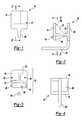
- FIG. 2is a cross-sectional view of the tool of FIG. 1 taken along the line 2 — 2 in FIG. 1;
- FIG. 6is a view similar to FIG. 3 but illustrating the tool in operative association with a boot seal assembly and a housing;
- FIG. 7is a top view of a tool constructed in accordance with a second embodiment of the present invention.
- FIG. 8is a side view of the tool of FIG. 7;
- FIG. 9is an end view of the tool of FIG. 7.
- FIG. 10is a view of the tool of FIG. 7 in operative association with a boot seal assembly and a transfer case output shaft.
- Tool 10is preferably unitarily formed from plastic or a similar material so as not to damage the seals with which tool 10 comes into contact.
- tool 10is shown to be a clip structure 12 having first and second vertically projecting members 14 and 16 , respectively, an axial body portion 18 , an axially projecting portion 20 , an upper gusset 22 and a pair of lower gussets 24 .
- Axially projecting portion 20is coupled to second vertically projecting member 16 and extends rearward therefrom.
- Axially projecting portion 20is generally cylindrical in shape with a generally circular cross-section.
- axially projecting portion 20may be flattened somewhat to minimize its height.
- the surface portion of axially projecting portion 20 that is adapted to contact the member to be sealedmay be contoured to match the surface of the member to be sealed so as to further reduce the effort with which a seal is installed.
- Boot seal assembly 50is shown to include a boot seal 52 and a clamp structure 54 .
- Boot seal 52is conventional in construction and is formed from an elastomeric material.
- Boot seal 52includes a wall member 56 , an annular sealing lip 58 and an annular clamp groove 60 .
- Annular sealing lip 58includes a chamfer 62 which breaks the sharp edge that would otherwise be formed by the intersection of the front face 64 and the inner face 66 of sealing lip 58 .
- Annular clamp groove 60is disposed within boot seal 52 behind chamfer 62 and is sized to receive clamp structure 54 .
- clamp structure 54is a band-type clamp that includes a band portion 68 and a crimp portion 70 .
- Clamp structure 54is disposed in annular clamp groove 60 and positionable between an uncompressed state and a compressed state. Placement of clamp structure 54 in the compressed state causes a radially directed clamp force to be exerted onto boot seal 52 to bring sealing lip 58 into contact with a sealing surface 76 of a structure to be sealed, such as a housing 78 .
- Tool 10is initially coupled to boot seal assembly 50 such that axially projecting portion 20 is in contact with the inner face 66 of sealing lip 58 , the crimp portion 70 of clamp structure 54 is disposed within crimp cavity 28 and first vertically projecting member 14 is coupled to crimp portion 70 .
- boot seal 52includes an annular groove 80 which intersects annular clamp groove 60 .
- Annular groove 80is sized to receive and permits sealing lip 58 to exert a forwardly directed force onto first vertically projecting member 14 .
- crimp cavity 28is sized to receive both crimp portion 70 and the front face 64 of boot seal 52
- the forwardly directed force exerted by sealing lip 58 against first vertically projecting member 14is countered by the front face 64 of boot seal 52 . This counterbalancing of forces tends to retain tool 10 to boot seal assembly 50 .
- Axially projecting portion 20extends axially across the inner face 66 of boot seal 52 to prevent tool 10 from lifting off seal assembly.
- tool 10may be withdrawn from boot seal assembly 50 .
- Finger pockets 30 in the lateral sides of tool 10are adapted to receive the fingers and/or thumb of a technician to permit tool 10 to be pulled from boot seal assembly 50 .
- Tool 10may thereafter be saved for re-use or may be disposed of.
- tool 10may be constructed as shown in FIGS. 7 through 9.
- tool 10 ′is shown to include a clip structure 12 ′ having first and second vertically projecting members 14 ′ and 16 ′, respectively, an axial body portion 18 ′, an axially projecting portion 20 ′ and a pair of lateral members 24 ′.
- Axial body portion 18 ′is coupled to first vertically projecting member 14 ′ at a first end and to second vertically projecting member 16 ′ at a second end.
- a first portion 150 of first vertically projecting member 14 ′depends in an upward and rearward direction away from axial body portion 18 ′.
- a second portion 152 of first vertically projecting member 14 ′depends in a downward direction generally perpendicular to axial body portion 18 ′.
- a third portion 154 of first vertically projecting member 14 ′depends in a downward and forward direction relative to axial body portion 18 ′.
- the second and third portions 152 and 154 of first vertically projecting member 14 ′cooperate to form a hook structure 156 , the purpose of which will be described in detail, below.
- Each lateral member 24 ′includes a laterally projecting portion 158 and a vertically projecting portion 160 .
- the forward edge 162 of each of the laterally projecting portions 158are coupled to an opposite lateral side of axial body portion 18 ′. Coupling the lateral members 24 ′ to the axial body portion 18 ′ in this manner produces a U-shaped groove 164 between the axial body portion 18 ′ and the rearward edge 166 of the laterally projecting portions 158 .
- First and second vertically projecting members 14 ′ and 16 ′ and the pair of lateral members 24 ′cooperate to form a crimp cavity 28 ′ having the same purpose and function as crimp cavity 28 , discussed above.
- Axially projecting portion 20 ′is coupled to second vertically projecting member 16 ′ and extends rewardly therefrom.
- Axially projecting portion 20 ′is generally cylindrical in shape with a generally circular cross-section, but may also be flattened or curved as discussed above.
- boot seal assembly 50 ′is illustrated in operative association with a boot seal assembly 50 ′.
- Boot seal assembly 50 ′is shown to include a boot seal 52 ′ and a clamp structure 54 ′.
- Boot seal 52 ′is largely conventional in construction, being formed from an elastomeric material and having a wall member 56 ′, an annular sealing lip 58 ′ and an annular clamp groove 60 ′.
- Annular sealing lip 58 ′includes a chamfer 62 ′ which breaks the sharp edge that would otherwise be formed by the intersection of the front face 64 ′ and the inner face 66 ′ of sealing lip 58 ′.
- Annular clamp groove 60 ′is disposed within boot seal 52 ′ behind chamfer 62 ′ and is sized to receive clamp structure 54 ′.
- clamp structure 54 ′is a band-type clamp that includes a band portion 68 ′ and a crimp portion 70 ′.
- Clamp structure 54 ′is disposed in annular clamp groove 60 ′ and positionable between an uncompressed state and a compressed state. Placement of clamp structure 54 ′ in the compressed state causes a radially directed clamp force to be exerted onto boot seal 52 ′ to bring sealing lip 58 ′ into contact with a sealing surface 76 ′ of a structure to be sealed, such as a transfer case output shaft 78 ′.
- Tool 10 ′is initially coupled to boot seal assembly 50 ′ such that axially projecting portion 20 ′ is in contact with the inner face 66 ′ of sealing lip 58 ′, the crimp portion 70 ′ of clamp structure 54 ′ is disposed within crimp cavity 28 ′ and a hook structure 156 is coupled to crimp portion 70 ′.
- the third portion 154 of first vertically projecting member 14 ′hooks under crimp portion 70 ′.
- Hook structure 156is configured to exert a forwardly directed force through clamp structure 54 ′.
- crimp cavity 28 ′is sized to receive both crimp portion 70 ′ and the front face 64 ′ of boot seal 52 ′
- the forwardly directed force exerted by hook structure 156is countered by the resiliency of the front face 64 ′ of boot seal 52 ′. This counterbalancing of forces tends to retain tool 10 ′ to boot seal assembly 50 ′.
- Axially projecting portion 20 ′extends axially across the inner face 66 ′ of boot seal 52 ′ to prevent tool 10 ′ from lifting off seal assembly.
- tool 10 ′can be preinstalled to boot seal assembly 50 ′ to form a seal assembly 90 ′.
- Seal assembly 90 ′is then coupled to transfer case output shaft 78 ′ such that sealing lip 58 ′ is in contact with substantially all of the sealing surface 76 ′.
- Axially projecting portion 20 ′is also in contact with sealing surface 76 ′ and as such, prevents sealing lip 58 ′ from completely engaging sealing surface 76 ′.
- axially projecting portion 20 ′remains in contact with sealing surface 76 ′.
- sealing lip 58 ′ proximate axially projecting portion 20 ′rises above sealing surface 76 ′ and forms a vent 92 ′ which is operable for inhibiting the build-up of fluid pressure within boot seal 52 ′ when seal assembly 90 ′ is installed to transfer case output shaft 78 ′.
- tool 10 ′may be withdrawn from boot seal assembly 50 ′.
- An upwardly and forwardly directed forcemay be applied to the first portion 150 of first vertically projecting member 14 ′ to create a levering effect which causes hook structure 156 to disengage crimp portion 70 ′.
- the U-shaped slots 164 and the necked-down portion 180 of axial body portion 18 ′cooperate to provide first vertically projecting member 14 ′ with a desired degree of flexibility.
- Tool 10 ′may then be pulled from boot seal 50 ′ and saved for re-use or disposed of.
Landscapes
- Engineering & Computer Science (AREA)
- General Engineering & Computer Science (AREA)
- Mechanical Engineering (AREA)
- Sealing Devices (AREA)
Abstract
Description
Claims (18)
Priority Applications (1)
| Application Number | Priority Date | Filing Date | Title |
|---|---|---|---|
| US09/519,054US6354602B1 (en) | 2000-03-03 | 2000-03-03 | Assembly vent for boot/seal installation |
Applications Claiming Priority (1)
| Application Number | Priority Date | Filing Date | Title |
|---|---|---|---|
| US09/519,054US6354602B1 (en) | 2000-03-03 | 2000-03-03 | Assembly vent for boot/seal installation |
Publications (1)
| Publication Number | Publication Date |
|---|---|
| US6354602B1true US6354602B1 (en) | 2002-03-12 |
Family
ID=24066586
Family Applications (1)
| Application Number | Title | Priority Date | Filing Date |
|---|---|---|---|
| US09/519,054Expired - LifetimeUS6354602B1 (en) | 2000-03-03 | 2000-03-03 | Assembly vent for boot/seal installation |
Country Status (1)
| Country | Link |
|---|---|
| US (1) | US6354602B1 (en) |
Cited By (8)
| Publication number | Priority date | Publication date | Assignee | Title |
|---|---|---|---|---|
| US20030040711A1 (en)* | 1997-05-28 | 2003-02-27 | Racenet David C. | Trocar seal system |
| US6702787B2 (en)* | 1997-05-02 | 2004-03-09 | Tyco Healthcare Group Lp | Trocar seal system |
| US20040099322A1 (en)* | 2002-06-10 | 2004-05-27 | Wang Shen-Ling Allen | Vent for a constant velocity joint |
| US20040144603A1 (en)* | 2003-01-24 | 2004-07-29 | Sean Barrett | Pressure bleeding boot-type seal |
| US20070087847A1 (en)* | 2005-10-13 | 2007-04-19 | American Axle & Manufacturing, Inc. | Propshaft boot with integrated bearing seal deflector |
| US20100160052A1 (en)* | 2008-11-26 | 2010-06-24 | Ledford Kevin M | Universal joint with trunnion shaft seal assembly |
| US8316731B2 (en) | 2008-10-10 | 2012-11-27 | American Axle & Manufacturing, Inc. | Power transmission device with torque-resistant seal |
| WO2021054966A1 (en)* | 2019-09-20 | 2021-03-25 | Borgwarner Inc. | Solenoid-actuated valve and hydraulic control module including the same |
Citations (14)
| Publication number | Priority date | Publication date | Assignee | Title |
|---|---|---|---|---|
| US3208779A (en)* | 1962-10-22 | 1965-09-28 | Gen Motors Corp | Ball joint dirt seal valve |
| US3441298A (en)* | 1966-03-07 | 1969-04-29 | Trw Inc | Purgible seal assembly |
| US3927576A (en)* | 1974-08-01 | 1975-12-23 | Trw Inc | Boot seal filter vent |
| US4210002A (en)* | 1978-01-04 | 1980-07-01 | Societe Anonyme Automobiles Citroen | Transmission joint with bellows dust-guard |
| US4224808A (en)* | 1979-01-15 | 1980-09-30 | General Motors Corporation | Venting arrangement for stroking universal joint |
| US4392838A (en)* | 1980-03-13 | 1983-07-12 | Lohr & Bromkamp Gmbh | Sealing boot for universal joint |
| US4506768A (en) | 1977-07-20 | 1985-03-26 | Lucas Industries Public Limited Company | Boot assembly |
| US4549830A (en)* | 1983-11-22 | 1985-10-29 | Trw Ehrenreich Gmbh & Co. Kg | Fastening of a sealing bellows to the joint housing of a ball joint |
| US4556400A (en)* | 1981-08-05 | 1985-12-03 | Uni-Cardan Aktiengesellschaft | Drive shaft assembly for motor vehicles |
| US4559025A (en)* | 1983-04-15 | 1985-12-17 | Automobiles Citroen | Universal joint with bellows seal and vent |
| US4671586A (en) | 1984-12-17 | 1987-06-09 | General Motors Corporation | Spark plug shield and boot seal assembly |
| US5015002A (en)* | 1990-06-29 | 1991-05-14 | Daystar, Inc. | Protective bellows |
| USRE33701E (en) | 1987-09-11 | 1991-09-24 | Arco Industries Corporation | Steering column boot |
| US5261678A (en) | 1991-03-29 | 1993-11-16 | Akebono Brake Industry Co., Ltd. | Dust-proof boot and method for mounting the same |
- 2000
- 2000-03-03USUS09/519,054patent/US6354602B1/ennot_activeExpired - Lifetime
Patent Citations (14)
| Publication number | Priority date | Publication date | Assignee | Title |
|---|---|---|---|---|
| US3208779A (en)* | 1962-10-22 | 1965-09-28 | Gen Motors Corp | Ball joint dirt seal valve |
| US3441298A (en)* | 1966-03-07 | 1969-04-29 | Trw Inc | Purgible seal assembly |
| US3927576A (en)* | 1974-08-01 | 1975-12-23 | Trw Inc | Boot seal filter vent |
| US4506768A (en) | 1977-07-20 | 1985-03-26 | Lucas Industries Public Limited Company | Boot assembly |
| US4210002A (en)* | 1978-01-04 | 1980-07-01 | Societe Anonyme Automobiles Citroen | Transmission joint with bellows dust-guard |
| US4224808A (en)* | 1979-01-15 | 1980-09-30 | General Motors Corporation | Venting arrangement for stroking universal joint |
| US4392838A (en)* | 1980-03-13 | 1983-07-12 | Lohr & Bromkamp Gmbh | Sealing boot for universal joint |
| US4556400A (en)* | 1981-08-05 | 1985-12-03 | Uni-Cardan Aktiengesellschaft | Drive shaft assembly for motor vehicles |
| US4559025A (en)* | 1983-04-15 | 1985-12-17 | Automobiles Citroen | Universal joint with bellows seal and vent |
| US4549830A (en)* | 1983-11-22 | 1985-10-29 | Trw Ehrenreich Gmbh & Co. Kg | Fastening of a sealing bellows to the joint housing of a ball joint |
| US4671586A (en) | 1984-12-17 | 1987-06-09 | General Motors Corporation | Spark plug shield and boot seal assembly |
| USRE33701E (en) | 1987-09-11 | 1991-09-24 | Arco Industries Corporation | Steering column boot |
| US5015002A (en)* | 1990-06-29 | 1991-05-14 | Daystar, Inc. | Protective bellows |
| US5261678A (en) | 1991-03-29 | 1993-11-16 | Akebono Brake Industry Co., Ltd. | Dust-proof boot and method for mounting the same |
Cited By (25)
| Publication number | Priority date | Publication date | Assignee | Title |
|---|---|---|---|---|
| US8267898B2 (en) | 1997-05-02 | 2012-09-18 | Tyco Healthcare Group Lp | Trocar seal system |
| US6702787B2 (en)* | 1997-05-02 | 2004-03-09 | Tyco Healthcare Group Lp | Trocar seal system |
| US8702657B2 (en) | 1997-05-02 | 2014-04-22 | Covidien Lp | Trocar seal system |
| US8192405B2 (en) | 1997-05-02 | 2012-06-05 | Tyco Healthcare Group Lp | Trocar seal system |
| US8002934B2 (en) | 1997-05-02 | 2011-08-23 | Tyco Healthcare Group Lp | Trocar seal system |
| US20090318868A1 (en)* | 1997-05-02 | 2009-12-24 | Tyco Healthcare Group Lp | Trocar seal system |
| US7896846B2 (en) | 1997-05-02 | 2011-03-01 | Tyco Healthcare Group Lp | Trocar seal system |
| US10426516B2 (en) | 1997-05-28 | 2019-10-01 | Covidien Lp | Trocar seal system |
| US7244244B2 (en) | 1997-05-28 | 2007-07-17 | Tyco Healthcare Group Lp | Trocar seal system |
| US20070197972A1 (en)* | 1997-05-28 | 2007-08-23 | Tyco Healthcare Group Lp | Trocar seal system |
| US20030040711A1 (en)* | 1997-05-28 | 2003-02-27 | Racenet David C. | Trocar seal system |
| US20040099322A1 (en)* | 2002-06-10 | 2004-05-27 | Wang Shen-Ling Allen | Vent for a constant velocity joint |
| US6830074B2 (en)* | 2002-06-10 | 2004-12-14 | Gkn Driveline North America, Inc. | Vent for a constant velocity joint |
| US20040144603A1 (en)* | 2003-01-24 | 2004-07-29 | Sean Barrett | Pressure bleeding boot-type seal |
| US7097004B2 (en) | 2003-01-24 | 2006-08-29 | Akebono Corporation (North America) | Pressure bleeding boot-type seal |
| US20080153608A1 (en)* | 2005-10-13 | 2008-06-26 | American Axle & Manufacturing, Inc. | Power transmission device with slip spline shaft assembly having boot integrated deflector |
| US20070087847A1 (en)* | 2005-10-13 | 2007-04-19 | American Axle & Manufacturing, Inc. | Propshaft boot with integrated bearing seal deflector |
| US7513831B2 (en) | 2005-10-13 | 2009-04-07 | American Axle & Manufacturing, Inc. | Power transmission device with slip spline shaft assembly having boot integrated deflector |
| US7338384B2 (en) | 2005-10-13 | 2008-03-04 | American Axle & Manufacturing, Inc. | Propshaft boot with integrated bearing seal deflector |
| US8316731B2 (en) | 2008-10-10 | 2012-11-27 | American Axle & Manufacturing, Inc. | Power transmission device with torque-resistant seal |
| US8142292B2 (en) | 2008-11-26 | 2012-03-27 | American Axle & Manufacturing, Inc. | Universal joint with trunnion shaft seal assembly |
| US20100160052A1 (en)* | 2008-11-26 | 2010-06-24 | Ledford Kevin M | Universal joint with trunnion shaft seal assembly |
| WO2021054966A1 (en)* | 2019-09-20 | 2021-03-25 | Borgwarner Inc. | Solenoid-actuated valve and hydraulic control module including the same |
| CN114651133A (en)* | 2019-09-20 | 2022-06-21 | 博格华纳公司 | Solenoid actuated valve and hydraulic control module including solenoid actuated valve |
| CN114651133B (en)* | 2019-09-20 | 2025-08-08 | 博格华纳公司 | Solenoid-actuated valve and hydraulic control module including the same |
Similar Documents
| Publication | Publication Date | Title |
|---|---|---|
| US4884829A (en) | Plug-in connection for connecting tube and host lines in particular for use in tube-line systems of motor vehicles | |
| US4021062A (en) | Coupling assemblies | |
| EP1250970B1 (en) | Resin tube joint with reinforcing ring | |
| US7461848B2 (en) | Snap in place gasket for sealing plastic pipelines and method of installation | |
| US7641239B2 (en) | Assembly of male and female members | |
| EP2503207B1 (en) | Pipe joint | |
| US6354602B1 (en) | Assembly vent for boot/seal installation | |
| US20040207195A1 (en) | Locator tab and associated hose clamp | |
| CN102947629A (en) | Annular elastic gasket | |
| US4429886A (en) | Flexible pipe gasket | |
| US8801045B2 (en) | Pipe joint | |
| CA2316102A1 (en) | Method and forming element for producing a press connection between a fitting and a pipe that is inserted into the reception of the fitting | |
| EP0763688B1 (en) | Pipe joint | |
| JP2706629B2 (en) | Pipe fittings | |
| EP1162399A3 (en) | Automotive hose coupling | |
| JP4292321B2 (en) | gasket | |
| KR101104085B1 (en) | Pipe connector | |
| EP3441537A1 (en) | Improved toilet pan connector | |
| US20010040348A1 (en) | Pipe connecting gaskets | |
| JP2673931B2 (en) | Method for preventing rust around pipe water passage and its parts | |
| CN113446448B (en) | Bellows connecting device | |
| CN216201349U (en) | Anti-slip sealing ring for pipeline connection | |
| CN210318563U (en) | Throttle valve with locking and mounting structure | |
| JP3666614B2 (en) | Radial tire repair method and repair tool | |
| JP3433669B2 (en) | Reserve tank for oil pump |
Legal Events
| Date | Code | Title | Description |
|---|---|---|---|
| AS | Assignment | Owner name:AMERICAN AXLE & MANUFACTURING, INC., MICHIGAN Free format text:ASSIGNMENT OF ASSIGNORS INTEREST;ASSIGNOR:OLDENBURG, THOMAS J.;REEL/FRAME:010605/0630 Effective date:20000216 | |
| AS | Assignment | Owner name:CHASE MANHATTAN BANK, AS COLLATERAL AGENT, THE, NE Free format text:SUPPLEMENT TO INTELLECTUAL PROPERTY SECURITY AGREE;ASSIGNORS:AMERICAN AXLE & MANUFACTURING, INC.;MSP INDUSTRIES CORPORATION;COLFOR MANUFACTURING, INC.;REEL/FRAME:012177/0112 Effective date:20010815 | |
| STCF | Information on status: patent grant | Free format text:PATENTED CASE | |
| AS | Assignment | Owner name:JPMORGAN CHASE BANK, AS COLLATERAL AGENT, NEW YORK Free format text:SUPPLEMENT;ASSIGNOR:AMERICAN AXLE & MANUFACTURING, INC.;REEL/FRAME:013813/0399 Effective date:20030221 | |
| CC | Certificate of correction | ||
| AS | Assignment | Owner name:AMERICAN AXLE & MANUFACTURING, INC., MICHIGAN Free format text:SECURITY AGREEMENT RELEASE;ASSIGNOR:JPMORGAN CHASE BANK;REEL/FRAME:014926/0190 Effective date:20040116 | |
| FPAY | Fee payment | Year of fee payment:4 | |
| FPAY | Fee payment | Year of fee payment:8 | |
| FPAY | Fee payment | Year of fee payment:12 | |
| AS | Assignment | Owner name:JPMORGAN CHASE BANK, N.A., AS COLLATERAL AGENT, NE Free format text:SECURITY INTEREST;ASSIGNORS:AMERICAN AXLE & MANUFACTURING, INC.;CLOYES GEAR AND PRODUCTS, INC.;GREDE LLC;AND OTHERS;REEL/FRAME:042734/0001 Effective date:20170605 Owner name:JPMORGAN CHASE BANK, N.A., AS COLLATERAL AGENT, NEW YORK Free format text:SECURITY INTEREST;ASSIGNORS:AMERICAN AXLE & MANUFACTURING, INC.;CLOYES GEAR AND PRODUCTS, INC.;GREDE LLC;AND OTHERS;REEL/FRAME:042734/0001 Effective date:20170605 |