US6354337B1 - Oven baster and cleaning brush - Google Patents
Oven baster and cleaning brushDownload PDFInfo
- Publication number
- US6354337B1 US6354337B1US09/649,212US64921200AUS6354337B1US 6354337 B1US6354337 B1US 6354337B1US 64921200 AUS64921200 AUS 64921200AUS 6354337 B1US6354337 B1US 6354337B1
- Authority
- US
- United States
- Prior art keywords
- tube
- baster
- cleaning brush
- shank
- bulb
- Prior art date
- Legal status (The legal status is an assumption and is not a legal conclusion. Google has not performed a legal analysis and makes no representation as to the accuracy of the status listed.)
- Expired - Lifetime
Links
- 238000004140cleaningMethods0.000titleclaimsabstractdescription59
- 239000000523sampleSubstances0.000claimsabstractdescription22
- 239000000463materialSubstances0.000claimsdescription19
- 230000007704transitionEffects0.000claimsdescription8
- 238000007789sealingMethods0.000claimsdescription7
- 239000003570airSubstances0.000claimsdescription6
- 239000012080ambient airSubstances0.000claimsdescription6
- 239000002245particleSubstances0.000claimsdescription6
- 238000006748scratchingMethods0.000claimsdescription4
- 230000002393scratching effectEffects0.000claimsdescription4
- 239000002253acidSubstances0.000claimsdescription3
- 229920000515polycarbonatePolymers0.000claims1
- 239000004417polycarbonateSubstances0.000claims1
- 239000012530fluidSubstances0.000description12
- 235000013305foodNutrition0.000description7
- 239000011521glassSubstances0.000description5
- 238000005259measurementMethods0.000description4
- XLYOFNOQVPJJNP-UHFFFAOYSA-NwaterSubstancesOXLYOFNOQVPJJNP-UHFFFAOYSA-N0.000description4
- 238000010411cookingMethods0.000description3
- 239000007788liquidSubstances0.000description3
- 239000004033plasticSubstances0.000description3
- 229920003023plasticPolymers0.000description3
- 239000003599detergentSubstances0.000description2
- 230000001939inductive effectEffects0.000description2
- 238000007689inspectionMethods0.000description2
- 239000002184metalSubstances0.000description2
- 239000012858resilient materialSubstances0.000description2
- 210000003813thumbAnatomy0.000description2
- 125000000391vinyl groupChemical group[H]C([*])=C([H])[H]0.000description2
- 229920002554vinyl polymerPolymers0.000description2
- 229920004142LEXAN™Polymers0.000description1
- 239000004677NylonSubstances0.000description1
- 229910000831SteelInorganic materials0.000description1
- 150000007513acidsChemical class0.000description1
- 239000005391art glassSubstances0.000description1
- 230000004323axial lengthEffects0.000description1
- 238000009835boilingMethods0.000description1
- 230000003749cleanlinessEffects0.000description1
- 239000011248coating agentSubstances0.000description1
- 238000000576coating methodMethods0.000description1
- 230000001186cumulative effectEffects0.000description1
- 238000001035dryingMethods0.000description1
- 230000000694effectsEffects0.000description1
- 239000013536elastomeric materialSubstances0.000description1
- 210000005224forefingerAnatomy0.000description1
- 238000003780insertionMethods0.000description1
- 230000037431insertionEffects0.000description1
- 230000003993interactionEffects0.000description1
- 230000033001locomotionEffects0.000description1
- 230000014759maintenance of locationEffects0.000description1
- 235000013372meatNutrition0.000description1
- 230000005499meniscusEffects0.000description1
- 229920001778nylonPolymers0.000description1
- 239000004431polycarbonate resinSubstances0.000description1
- 229920005668polycarbonate resinPolymers0.000description1
- 244000144977poultrySpecies0.000description1
- 230000003763resistance to breakageEffects0.000description1
- 229920003031santoprenePolymers0.000description1
- 239000007787solidSubstances0.000description1
- 239000010959steelSubstances0.000description1
- 239000000126substanceSubstances0.000description1
- 229920002725thermoplastic elastomerPolymers0.000description1
- 238000005406washingMethods0.000description1
Images


Classifications
- A—HUMAN NECESSITIES
- A47—FURNITURE; DOMESTIC ARTICLES OR APPLIANCES; COFFEE MILLS; SPICE MILLS; SUCTION CLEANERS IN GENERAL
- A47J—KITCHEN EQUIPMENT; COFFEE MILLS; SPICE MILLS; APPARATUS FOR MAKING BEVERAGES
- A47J43/00—Implements for preparing or holding food, not provided for in other groups of this subclass
- A47J43/005—Basting devices
- A—HUMAN NECESSITIES
- A46—BRUSHWARE
- A46B—BRUSHES
- A46B11/00—Brushes with reservoir or other means for applying substances, e.g. paints, pastes, water
- A46B11/0006—Brushes with reservoir or other means for applying substances, e.g. paints, pastes, water specially adapted to feed the bristle upper surface
- A—HUMAN NECESSITIES
- A46—BRUSHWARE
- A46B—BRUSHES
- A46B11/00—Brushes with reservoir or other means for applying substances, e.g. paints, pastes, water
- A46B11/001—Brushes with reservoir or other means for applying substances, e.g. paints, pastes, water with integral reservoirs
- A46B11/002—Brushes with reservoir or other means for applying substances, e.g. paints, pastes, water with integral reservoirs pressurised at moment of use manually or by powered means
- A46B11/0041—Flexible or deformable reservoirs, e.g. resilient bulbs, compressible tubes
- A—HUMAN NECESSITIES
- A46—BRUSHWARE
- A46B—BRUSHES
- A46B2200/00—Brushes characterized by their functions, uses or applications
- A46B2200/20—Brushes for applying products to surfaces in general
Definitions
- This inventionrelates to cooking utensils, namely oven basters, and more particularly to an oven baster and a cleaning brush therefor.
- a cooking utensil that is useful in the kitchenis the oven baster.
- Such a utensilis used to apply liquids to foods, typically meat or poultry, that are being baked or roasted in an oven. The liquid is applied periodically during cooking to prevent excessive drying of the food or to add flavorings.
- prior oven bastershave included a tube of relatively large diameter having a tip portion of reduced diameter at one end and a compressible, self-expanding bulb at the other end. With the bulb compressed, the tip portion is placed in a reservoir of basting fluid. Pressure on the bulb is then released, allowing the bulb to self-expand and draw fluid into the tube. By positioning the tip portion over the food to be basted and again compressing the bulb, the fluid is expelled from the tube through the tip portion and onto the food.
- the liquids that are typically dispensed using an oven basteroften include solid particles or other substances that adhere to the interior surface of the basting tube, or that are large enough to become lodged in the tip portion of the tube. It is necessary to clean the interior of the tube after use. This can be accomplished by disassembling the tube and bulb and using a bottle-type brush to clean the interior of the basting tube. Such brushes, if sized for the relatively large diameter of the reservoir portion of the tube, are too large to fit within the smaller diameter tip portion. Either the tip portion must be cleaned with water and determent alone, or some other utensil of small diameter must be used to clean or dislodge matter from the tip portion, which is inconvenient at best.
- Prior oven bastershave employed tubes constructed of various materials, such as metal, glass and opaque or translucent plastic. Glass and metal are resistant to heat deformation. Glass also has the advantage of being transparent, which favors inspection and measurement of basting fluid within the tube, and also verifying cleanliness of the interior of the tube. Glass is quite easily broken during storage or use, however. Opaque or translucent plastic is resistant to breakage, but is not as heat resistant as glass and does not have the advantages of transparency.
- the present inventionincludes a baster having a tube with a tip portion and a reservoir portion.
- the tubeis comprised of a substantially transparent polymeric material.
- a compressible bulbis in communication with the reservoir portion of the tube. The bulb is resiliently self-expandable to induce reduced air pressure in the tube relative to ambient air pressure.
- a cleaning brush for a tubeincludes a handle having a proximate end and a distal end.
- a longitudinal shankextends distally from the distal end of the handle, and plurality of bristles extend substantially transversely from the shank.
- An elongate cleaning probeextends distally from the distal end of the handle.
- a baster and cleaning brush setis provided.
- a basterhaving a tube with a reservoir portion and a tip portion, and a compressible bulb in communication with the reservoir portion of the tube.
- the bulbis resiliently self-expandable to induce reduced air pressure in the tube relative to ambient air pressure.
- a cleaning brush for the tubehaving a handle with a proximate end and a distal end.
- a longitudinal shankextends distally from the distal end of the handle.
- a plurality of bristlesextend substantially transversely from the shank.
- An elongate cleaning probeextends distally from the distal end of the handle.
- FIG. 1is a perspective view of an oven baster in accordance with the present invention, the bulb and tube being assembled;
- FIG. 2is a perspective view of the oven baster of FIG. 1, the bulb and tube being disassembled;
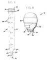
- FIG. 3is an elevational view of the tube of the oven baster of FIG. 1;
- FIG. 4is an elevational view, partially in section, of the bulb of the oven baster of FIG. 1;
- FIG. 5is a perspective view of a cleaning brush that is useful with the oven baster of FIG. 1;
- FIG. 6is a front elevational view of the cleaning brush of FIG. 5;
- FIG. 7is a side elevational view of the cleaning brush of FIG. 5;
- FIG. 8is a perspective view of the cleaning brush of FIG. 5 received in cleaning engagement in the tube of the oven baster of FIG. 1;
- FIG. 9is a front elevational view of the handle of the cleaning brush of FIG. 5, and a front elevational view of the tube of the oven baster of FIG. 1, the cleaning probe of the handle being aligned with the tip portion of the tube;
- FIG. 10is a front elevational view of the handle of the cleaning brush of FIG. 5, and a front elevational view of the tube of the oven baster of FIG. 1, the cleaning probe of the handle being received within the tip portion of the tube.
- Tube 12is generally elongate, hollow, and symmetrical about a longitudinal axis, and includes a reservoir portion 16 , a transition segment 18 , and a tip portion 20 .
- Reservoir portion 16includes a first open end 22 and a second end 24 and is tapered substantially linearly therebetween, with first end 22 having a diameter larger than the diameter of second end 24 .
- Transition segment 18extends integrally from second end 24 of reservoir portion 16 and undergoes a non-linear, i.e., curved, reduction in diameter between a first end 26 , connected to second end 24 of reservoir portion 16 , and a second end 28 .
- Tip portion 20extends integrally from second end 24 of transition segment 18 and is tapered substantially linearly between a first end 30 , connected to second end 28 of transition segment 18 , and a second, open end 32 .
- First end 30 of tip portion 20has a diameter substantially equal to the diameter of second end 28 of transition segment 18 and larger than the diameter of open second end 32 .
- Reservoir portion 16 , transition segment 18 and tip portion 20together define an interior, elongate passage in continuous communication from open end 22 of reservoir portion 16 to open end 32 of tip portion 20 .
- annular stop 34Spaced from open end 22 of tube 12 is an annular stop 34 extending radially outwardly from reservoir portion 16 and having a diameter larger than the diameter of reservoir portion 16 adjacent thereto. Spaced between open end 22 of tube 12 and annular stop 34 is an annular sealing ring 36 extending radially outwardly from reservoir portion 16 and having a diameter larger than the diameter of reservoir portion 16 adjacent thereto, but smaller than the outer diameter of annular stop 34 . Sealing ring 36 and annular stop 34 cooperate with bulb 14 as described further below.
- a series of indiciamarking the cumulative volume of the internal passage defined by tube 12 as measured from tip portion 20 toward open end 22 .
- One series of indicia 38(see FIG. 1) is located along one side of tube 12 and is marked in English units of measurement, i.e., in units of fluid ounces and fractions thereof.
- Another series of indicia 40(see FIG. 2) is located along another side of tube 12 opposite the first series of indicia 38 and is marked in metric units of measurement, i.e., in units of milliliters.
- Both series of indicia 38 and 40are integrally molded into the material of which tube 12 is constructed and are therefore substantially permanent, being highly resistant to being removed by wear or repeated washing.
- Tube 12is preferably constructed of a transparent polymeric material that is substantially rigid, resistant to breakage, resistant to acids that may be encountered in certain foods, and resistant to high temperatures on the order of those encountered in a dishwasher or from hot basting fluids which may be at the boiling point of water (100° C.) or higher.
- the transparency of tube 12permits ready inspection of fluids drawn into reservoir portion 16 and facilitates measurement of the volume of fluid so drawn because the location of the air-to-fluid meniscus is easily located and compared to the nearest indicia 38 or 40 .
- the material of which tube 12 is constructedis Lexan® 204 polycarbonate resin which is resistant to heat deformation at a temperature of 100° C., and up to about 118° C. So constructed, tube 12 enjoys the advantages of prior art glass basting tubes with respect to transparency and resistance to heat and acid, and also enjoys the advantage of prior art opaque plastic basting tubes with respect to resistance to breakage.
- bulb 14is shown assembled to tube 12 in FIG. 1, and shown disassembled therefrom in FIGS. 2 and 4.
- Bulb 14is preferably constructed of a flexible, resilient elastomeric material, and is hollow, compressible and self-expandable.
- bulb 14is constructed of Santoprene® 271-55 thermoplastic elastomer.
- tube 12 and bulb 14preferably should be disassembled. Disassembly and reassembly is facilitated by the flexible, resilient nature of the material from which bulb 14 is constructed.
- Bulb 14includes a bulbous portion 42 and a neck portion 44 of reduced diameter defining an opening 45 .
- the bulbous portion 42is significantly greater in diameter than reservoir portion 16 of tube 12 , whereas opening 45 of neck portion 44 has an internal diameter slightly smaller than the external diameter of open end 22 of tube 12 , when disassembled therefrom. Consequently, when bulb 14 is assembled to tube 12 , neck portion 44 stretches slightly in a flexible and resilient manner to overlie that portion of tube 12 adjacent open end 22 to effect a tight seal between bulb 14 and tube 12 . When so assembled, the interior passage of tube 12 is in communication with the hollow interior of bulb 14 . The seal is further assured, and retention of bulb 14 on tube 12 is facilitated, by the interaction of bulb 14 and sealing ring 36 of tube 12 . More particularly, neck portion 44 of bulb 14 includes an inner annular groove 46 formed in the bulb wall 48 (see FIG.
- the resiliently self-expandable characteristic of bulb 14permits bulb 14 to be squeezed and compressed, such as between a thumb and forefinger, while assembled to tube 12 . Subsequent relaxation of squeezing pressure permits bulb 14 to self-expand to its original configuration, thereby inducing reduced air pressure in tube 12 relative to ambient air pressure. In this manner, fluids can be sucked or drawn up into reservoir portion 16 of tube 12 through open end 32 of tip portion 20 . Subsequently, the fluids so drawn can be expelled through open end 32 of tip portion 20 by again compressing bulb 14 , thereby inducing increased air pressure in tube 12 above the fluids, relative to ambient air pressure.
- Brush 60includes a handle 62 having a proximate end 64 and a distal end 66 .
- Handle 62is of substantially even thickness in one transverse direction, as shown in FIG. 7, and is generally tapered in another transverse direction, as shown in FIGS. 5 and 6.
- Proximate end 64is generally rounded, as is distal end 66
- handle 62tapers from proximate end 64 toward distal end 66 .
- a concave thumb indent 70is provided to enhance gripping of handle 62 to prevent slippage in the user's hand.
- Handle 62is preferably constructed of the same flexible, resilient material of which bulb 14 is constructed, although other materials are contemplated.
- Shank 72Extending from distal end 66 of handle 62 is a longitudinal shank 72 comprising a pair of wires helically twisted about each other.
- Shank 72is embedded a sufficient distance within handle 62 to substantially prevent shank 72 from being separated from handle 62 under application of usual forces associated with the use of brush 60 as a cleaning implement.
- shank 72is embedded as handle 62 is molded thereabout.
- the wires from which shank 72 is comprisedpreferably are constructed of steel and coated with a polymeric material such as vinyl to prevent rusting, and also to prevent scratching of tube 12 during use, as described below.
- bristles 74Twisted between the pair of wires of shank 72 and extending generally radially therefrom are a plurality of bristles 74 , preferably comprising monofilament nylon. Bristles 74 are disposed along the distal portion 75 of shank 72 , from distal tip 76 of shank 72 to about the midway point between distal tip 76 and distal end 66 of handle 62 (See FIG. 5 ). Distal tip 76 , rather than presenting exposed wire ends, is coated with a polymeric material such as vinyl, smoothly contoured, to prevent rusting and especially to prevent the end of shank 72 from scratching tube 12 during use. The material coating distal tip 76 should be less hard than the material of which tube 12 is constructed. Preferably, bristles 74 taper in length toward distal tip 76 at approximately the same taper as that of reservoir portion 16 of tube 12 , to facilitate ease of insertion of brush 60 into tube 12 , as described below.
- Cleaning probe 78Extending from proximal end 64 of handle 62 is an elongate cleaning probe 78 that is integral with and constructed of the same flexible, resilient material as handle 62 .
- Cleaning probe 78has a length approximately corresponding to the axial length of tip portion 20 of tube 12 , and has a maximum outer diameter sufficiently small to permit entry of cleaning probe 78 into tip portion 20 through open end 32 .
- Cleaning probe 78has a textured surface 80 defined by a plurality of raised nibs. Other coarsely textured surfaces, such as ribbing, are also contemplated. Cleaning probe 78 with textured surface 80 provides a considerable advantage over prior art cleaning brushes by facilitating the removal of food particles or other materials from the interior surface of tip portion 20 , as described below.
- probe 78The cleaning effectiveness of probe 78 is enhanced by the flexibility of the material from which it is constructed, which permits the user to manipulate the cleaning probe 78 as needed to dislodge particles adhering within tip portion 20 .
- the textured surface of probe 78also enhances its cleaning effectiveness.
- FIG. 8the manner of using the bristles 74 of cleaning brush 60 to clean tube 12 is illustrated.
- distal tip 76 of brush 60is inserted within tube 12 through open end 22 , preferably in the presence of water and detergent.
- Brush 60can be repeatedly inserted into and withdrawn from tube 12 in a reciprocating fashion, or can be rotated within tube 12 , as desired, to clean the inner surface of tube 12 .
- the taper of bristles 74corresponds generally to the taper of reservoir portion 16
- brush 60can be readily inserted all the way to and within transition section 18 of tube 12 .
- cleaning probe 78is provided for cleaning tip portion 20 , as described further below.
- FIGS. 9 and 10the manner of using cleaning probe 78 of cleaning brush 60 is illustrated.
- brush 60is oriented relative to tube 12 oppositely to the orientation shown in FIG. 8, such that cleaning probe 78 is axially aligned with open end 32 of tip portion 20 , as shown in FIG. 9 .
- bristles 74are disposed entirely externally of tube 12 .
- cleaning probe 78is inserted axially into tip portion 20 , as shown in FIG. 10, and can be manipulated in reciprocating or rotating motions as desired and as necessary to dislodge food particles from and clean the inner surface of tip portion 20 .
Landscapes
- Engineering & Computer Science (AREA)
- Mechanical Engineering (AREA)
- Food Science & Technology (AREA)
- Brushes (AREA)
- Cleaning In General (AREA)
Abstract
Description
Claims (21)
Priority Applications (8)
| Application Number | Priority Date | Filing Date | Title |
|---|---|---|---|
| US09/649,212US6354337B1 (en) | 2000-08-28 | 2000-08-28 | Oven baster and cleaning brush |
| DE10196564TDE10196564B4 (en) | 2000-08-28 | 2001-08-23 | cleaning brush |
| AU2001287209AAU2001287209A1 (en) | 2000-08-28 | 2001-08-23 | Oven baster and cleaning brush |
| GB0306853AGB2384421B (en) | 2000-08-28 | 2001-08-23 | Cleaning brush |
| MXPA03001734AMXPA03001734A (en) | 2000-08-28 | 2001-08-23 | Oven baster and cleaning brush. |
| CA002420171ACA2420171C (en) | 2000-08-28 | 2001-08-23 | Oven baster and cleaning brush |
| CNB018149022ACN1245920C (en) | 2000-08-28 | 2001-08-23 | Oven baster and cleaning brush |
| PCT/US2001/041856WO2002018209A1 (en) | 2000-08-28 | 2001-08-23 | Oven baster and cleaning brush |
Applications Claiming Priority (1)
| Application Number | Priority Date | Filing Date | Title |
|---|---|---|---|
| US09/649,212US6354337B1 (en) | 2000-08-28 | 2000-08-28 | Oven baster and cleaning brush |
Publications (1)
| Publication Number | Publication Date |
|---|---|
| US6354337B1true US6354337B1 (en) | 2002-03-12 |
Family
ID=24603871
Family Applications (1)
| Application Number | Title | Priority Date | Filing Date |
|---|---|---|---|
| US09/649,212Expired - LifetimeUS6354337B1 (en) | 2000-08-28 | 2000-08-28 | Oven baster and cleaning brush |
Country Status (8)
| Country | Link |
|---|---|
| US (1) | US6354337B1 (en) |
| CN (1) | CN1245920C (en) |
| AU (1) | AU2001287209A1 (en) |
| CA (1) | CA2420171C (en) |
| DE (1) | DE10196564B4 (en) |
| GB (1) | GB2384421B (en) |
| MX (1) | MXPA03001734A (en) |
| WO (1) | WO2002018209A1 (en) |
Cited By (12)
| Publication number | Priority date | Publication date | Assignee | Title |
|---|---|---|---|---|
| WO2003086667A1 (en)* | 2002-04-06 | 2003-10-23 | Hydrophilix, Llc | Apparatus and method for cleaning an endoscope |
| US20050060825A1 (en)* | 2003-09-22 | 2005-03-24 | Stephen Hillenbrand | Clothes dryer lint cleaning brush |
| US20060102200A1 (en)* | 2004-11-18 | 2006-05-18 | Bernard Esquenet | Cannula cleaning device |
| USD521327S1 (en) | 2005-01-13 | 2006-05-23 | Wilton Industries, Inc. | Baster |
| US20070181007A1 (en)* | 2006-02-09 | 2007-08-09 | Browne & Co. | Basting device |
| US20100095853A1 (en)* | 2008-10-21 | 2010-04-22 | Helen Of Troy Limited | Easy-clean food baster |
| US20100192320A1 (en)* | 2009-02-02 | 2010-08-05 | Sanderson-Macleod, Inc. | Homogeneous core wire protective cleaning tip |
| US8365778B1 (en) | 2004-07-19 | 2013-02-05 | Decal Diego L | Turkey baster |
| USD689745S1 (en)* | 2012-02-16 | 2013-09-17 | Fox Run Usa, Llc | Baster |
| USD964821S1 (en)* | 2021-09-27 | 2022-09-27 | Shenzhen Youta Innovation Technology Co., Ltd. | Baster |
| USD1015525S1 (en)* | 2022-01-20 | 2024-02-20 | Zhejiang Orient Gene Biotech Co., LTD | Sample collector |
| US12336624B2 (en) | 2020-11-24 | 2025-06-24 | Sanderson Macleod, Inc. | Brush or swab assembly and method of manufacturing a brush or swab |
Families Citing this family (12)
| Publication number | Priority date | Publication date | Assignee | Title |
|---|---|---|---|---|
| AU753568B2 (en) | 1998-01-16 | 2002-10-24 | Trudell Medical International | Indicating device for use with a dispensing device |
| US6082358A (en) | 1998-05-05 | 2000-07-04 | 1263152 Ontario Inc. | Indicating device for aerosol container |
| US7004164B2 (en) | 2002-03-21 | 2006-02-28 | Trudell Medical International | Indicating device for aerosol container |
| US7621273B2 (en) | 2003-10-28 | 2009-11-24 | Trudell Medical International | Indicating device with warning dosage indicator |
| US7100530B2 (en) | 2003-12-15 | 2006-09-05 | Trudell Medical International, Inc. | Dose indicating device |
| US7543582B2 (en) | 2004-09-20 | 2009-06-09 | Trudell Medical International | Dose indicating device with display elements attached to container |
| WO2006077486A1 (en) | 2005-01-20 | 2006-07-27 | Trudell Medical International | Dispensing device |
| US8141550B2 (en) | 2006-08-01 | 2012-03-27 | Trudell Medical International | Dispensing device |
| US8082873B2 (en) | 2008-05-05 | 2011-12-27 | Trudell Medical International | Drive mechanism for an indicating device |
| US8181591B1 (en) | 2008-05-23 | 2012-05-22 | Trudell Medical International | Domed actuator for indicating device |
| CA2683353C (en) | 2008-10-22 | 2015-12-15 | Trudell Medical International | Modular aerosol delivery system |
| EP3669986A1 (en) | 2018-12-17 | 2020-06-24 | Hilgenberg GmbH | Suction device for pipettes |
Citations (4)
| Publication number | Priority date | Publication date | Assignee | Title |
|---|---|---|---|---|
| US5339480A (en)* | 1993-07-26 | 1994-08-23 | Murg Sandra D | Tint bottle and nozzle cleaning brush |
| US5615439A (en)* | 1994-11-30 | 1997-04-01 | La Technologie Avancee Medicale | Device for cleaning ducts in medical instruments |
| US5787799A (en)* | 1996-08-26 | 1998-08-04 | Versa Technologies, Inc. | Liquid baster |
| USD408106S (en)* | 1998-07-09 | 1999-04-13 | Dart Industries Inc. | Comined baby bottle and nipple cleaner |
Family Cites Families (4)
| Publication number | Priority date | Publication date | Assignee | Title |
|---|---|---|---|---|
| US2234884A (en)* | 1939-03-03 | 1941-03-11 | Florence M Teel | Basting device |
| DE1676361U (en)* | 1953-11-16 | 1954-05-13 | Gustav Goldbohm | SPOOL BRUSH WITH RUBBER HEAD. |
| DE1843634U (en)* | 1961-10-04 | 1961-12-21 | Hans Jun Haug | HANDLE BRUSH, IN PARTICULAR CLEANING BRUSH, BOTTLE BRUSH AND THE LIKE. |
| DE9400551U1 (en)* | 1994-01-14 | 1994-05-05 | Stasch, Günter, 76761 Rülzheim | Sauce sucker |
- 2000
- 2000-08-28USUS09/649,212patent/US6354337B1/ennot_activeExpired - Lifetime
- 2001
- 2001-08-23CNCNB018149022Apatent/CN1245920C/ennot_activeExpired - Fee Related
- 2001-08-23DEDE10196564Tpatent/DE10196564B4/ennot_activeExpired - Fee Related
- 2001-08-23WOPCT/US2001/041856patent/WO2002018209A1/enactiveApplication Filing
- 2001-08-23GBGB0306853Apatent/GB2384421B/ennot_activeExpired - Fee Related
- 2001-08-23AUAU2001287209Apatent/AU2001287209A1/ennot_activeAbandoned
- 2001-08-23MXMXPA03001734Apatent/MXPA03001734A/enactiveIP Right Grant
- 2001-08-23CACA002420171Apatent/CA2420171C/ennot_activeExpired - Fee Related
Patent Citations (4)
| Publication number | Priority date | Publication date | Assignee | Title |
|---|---|---|---|---|
| US5339480A (en)* | 1993-07-26 | 1994-08-23 | Murg Sandra D | Tint bottle and nozzle cleaning brush |
| US5615439A (en)* | 1994-11-30 | 1997-04-01 | La Technologie Avancee Medicale | Device for cleaning ducts in medical instruments |
| US5787799A (en)* | 1996-08-26 | 1998-08-04 | Versa Technologies, Inc. | Liquid baster |
| USD408106S (en)* | 1998-07-09 | 1999-04-13 | Dart Industries Inc. | Comined baby bottle and nipple cleaner |
Cited By (13)
| Publication number | Priority date | Publication date | Assignee | Title |
|---|---|---|---|---|
| WO2003086667A1 (en)* | 2002-04-06 | 2003-10-23 | Hydrophilix, Llc | Apparatus and method for cleaning an endoscope |
| US20050060825A1 (en)* | 2003-09-22 | 2005-03-24 | Stephen Hillenbrand | Clothes dryer lint cleaning brush |
| US8365778B1 (en) | 2004-07-19 | 2013-02-05 | Decal Diego L | Turkey baster |
| US20060102200A1 (en)* | 2004-11-18 | 2006-05-18 | Bernard Esquenet | Cannula cleaning device |
| USD521327S1 (en) | 2005-01-13 | 2006-05-23 | Wilton Industries, Inc. | Baster |
| US20070181007A1 (en)* | 2006-02-09 | 2007-08-09 | Browne & Co. | Basting device |
| US20100095853A1 (en)* | 2008-10-21 | 2010-04-22 | Helen Of Troy Limited | Easy-clean food baster |
| US20100192320A1 (en)* | 2009-02-02 | 2010-08-05 | Sanderson-Macleod, Inc. | Homogeneous core wire protective cleaning tip |
| US8850650B2 (en)* | 2009-02-02 | 2014-10-07 | Sanderson-Macleod, Inc. | Homogeneous core wire protective cleaning tip |
| USD689745S1 (en)* | 2012-02-16 | 2013-09-17 | Fox Run Usa, Llc | Baster |
| US12336624B2 (en) | 2020-11-24 | 2025-06-24 | Sanderson Macleod, Inc. | Brush or swab assembly and method of manufacturing a brush or swab |
| USD964821S1 (en)* | 2021-09-27 | 2022-09-27 | Shenzhen Youta Innovation Technology Co., Ltd. | Baster |
| USD1015525S1 (en)* | 2022-01-20 | 2024-02-20 | Zhejiang Orient Gene Biotech Co., LTD | Sample collector |
Also Published As
| Publication number | Publication date |
|---|---|
| WO2002018209A1 (en) | 2002-03-07 |
| MXPA03001734A (en) | 2004-09-10 |
| CA2420171A1 (en) | 2002-03-07 |
| CA2420171C (en) | 2009-06-09 |
| CN1245920C (en) | 2006-03-22 |
| GB2384421A (en) | 2003-07-30 |
| DE10196564T1 (en) | 2003-08-28 |
| GB0306853D0 (en) | 2003-04-30 |
| AU2001287209A1 (en) | 2002-03-13 |
| GB2384421A8 (en) | 2004-04-21 |
| CN1452574A (en) | 2003-10-29 |
| GB2384421B (en) | 2005-04-13 |
| DE10196564B4 (en) | 2010-06-24 |
Similar Documents
| Publication | Publication Date | Title |
|---|---|---|
| US6354337B1 (en) | Oven baster and cleaning brush | |
| CN206565924U (en) | Straw Cleaning System | |
| US5964004A (en) | Device for cleaning medical endoscopic tubes | |
| US8240938B2 (en) | Over cap brush for dispensing bottle | |
| EP3291874B1 (en) | A threaded connector port cleaning system, method, and apparatus | |
| US6418940B1 (en) | Interdental device and container | |
| JP2008544822A (en) | Device for use in cleaning the endoscope | |
| US20050135870A1 (en) | Combined toothbrush, toothpaste and mouthwash device | |
| US3085272A (en) | Test tube brushes | |
| US20050117962A1 (en) | Culinary brush | |
| US20230270244A1 (en) | Universal oral care tool | |
| US5813120A (en) | Food utensil and grate cleaning tool | |
| US20030041747A1 (en) | Device for draining a can of food | |
| US20070193453A1 (en) | Basting device | |
| US2629888A (en) | Device for cleaning feeding nipples for infants | |
| AU741733B2 (en) | Tube cleaner | |
| CN203943248U (en) | Improved structure of cleaning brush | |
| US20090080286A1 (en) | Beater cleaner | |
| CN111280787A (en) | A high-foot glass cleaning device | |
| CN206560143U (en) | A kind of brush of alterable size | |
| US8683914B1 (en) | Baster and method | |
| TWM577694U (en) | Improved straw | |
| CN102186355A (en) | Easy-clean food baster | |
| US10080631B2 (en) | Dental pipette | |
| CN109008179B (en) | A kind of toothpaste built-in finger toothbrush |
Legal Events
| Date | Code | Title | Description |
|---|---|---|---|
| AS | Assignment | Owner name:PAMPERED CHEF, LTD., THE, ILLINOIS Free format text:ASSIGNMENT OF ASSIGNORS INTEREST;ASSIGNORS:ODESSKY, BRUCE;PETERSON, SHANE;ROACH, ALISON A.;REEL/FRAME:012238/0825;SIGNING DATES FROM 20001221 TO 20010105 | |
| STCF | Information on status: patent grant | Free format text:PATENTED CASE | |
| AS | Assignment | Owner name:BH COLUMBIA, INC., NEBRASKA Free format text:ASSIGNMENT OF ASSIGNORS INTEREST;ASSIGNOR:PAMPERED CHEF, LTD., THE;REEL/FRAME:013456/0108 Effective date:20021030 | |
| AS | Assignment | Owner name:COLUMBIA INSURANCE COMPANY, NEBRASKA Free format text:ASSIGNMENT OF ASSIGNORS INTEREST;ASSIGNOR:BH COLUMBIA, INC.;REEL/FRAME:013484/0264 Effective date:20021030 | |
| FEPP | Fee payment procedure | Free format text:PAYOR NUMBER ASSIGNED (ORIGINAL EVENT CODE: ASPN); ENTITY STATUS OF PATENT OWNER: LARGE ENTITY | |
| CC | Certificate of correction | ||
| CC | Certificate of correction | ||
| FPAY | Fee payment | Year of fee payment:4 | |
| FEPP | Fee payment procedure | Free format text:PAYOR NUMBER ASSIGNED (ORIGINAL EVENT CODE: ASPN); ENTITY STATUS OF PATENT OWNER: LARGE ENTITY Free format text:PAYER NUMBER DE-ASSIGNED (ORIGINAL EVENT CODE: RMPN); ENTITY STATUS OF PATENT OWNER: LARGE ENTITY | |
| FPAY | Fee payment | Year of fee payment:8 | |
| FPAY | Fee payment | Year of fee payment:12 |