US6353774B1 - High precision vision guided positioning device - Google Patents
High precision vision guided positioning deviceDownload PDFInfo
- Publication number
- US6353774B1 US6353774B1US09/667,670US66767000AUS6353774B1US 6353774 B1US6353774 B1US 6353774B1US 66767000 AUS66767000 AUS 66767000AUS 6353774 B1US6353774 B1US 6353774B1
- Authority
- US
- United States
- Prior art keywords
- tray
- positioning device
- head assembly
- moving means
- elevator unit
- Prior art date
- Legal status (The legal status is an assumption and is not a legal conclusion. Google has not performed a legal analysis and makes no representation as to the accuracy of the status listed.)
- Expired - Fee Related
Links
- 230000033001locomotionEffects0.000claimsabstractdescription9
- 238000004140cleaningMethods0.000claimsdescription9
- 239000012528membraneSubstances0.000claimsdescription9
- 238000005406washingMethods0.000claimsdescription8
- 238000001035dryingMethods0.000claimsdescription5
- 241000894006BacteriaSpecies0.000description13
- 239000000499gelSubstances0.000description7
- 239000012472biological sampleSubstances0.000description6
- 238000012856packingMethods0.000description6
- 239000001963growth mediumSubstances0.000description4
- 238000012546transferMethods0.000description4
- 240000004808Saccharomyces cerevisiaeSpecies0.000description3
- 238000013461designMethods0.000description3
- 239000007788liquidSubstances0.000description3
- 238000000034methodMethods0.000description3
- 230000008569processEffects0.000description3
- 230000031018biological processes and functionsEffects0.000description2
- 210000000078clawAnatomy0.000description2
- 238000012544monitoring processMethods0.000description2
- 238000012545processingMethods0.000description2
- 239000000523sampleSubstances0.000description2
- 230000009897systematic effectEffects0.000description2
- 229920001817AgarPolymers0.000description1
- 239000008272agarSubstances0.000description1
- 230000009141biological interactionEffects0.000description1
- 230000008859changeEffects0.000description1
- 238000001514detection methodMethods0.000description1
- 238000002474experimental methodMethods0.000description1
- 239000011521glassSubstances0.000description1
- 230000013011matingEffects0.000description1
- 239000011159matrix materialSubstances0.000description1
- 230000010076replicationEffects0.000description1
- 230000003362replicative effectEffects0.000description1
- 125000006850spacer groupChemical group0.000description1
- 230000001954sterilising effectEffects0.000description1
- 238000012795verificationMethods0.000description1
Images


Classifications
- G—PHYSICS
- G01—MEASURING; TESTING
- G01N—INVESTIGATING OR ANALYSING MATERIALS BY DETERMINING THEIR CHEMICAL OR PHYSICAL PROPERTIES
- G01N35/00—Automatic analysis not limited to methods or materials provided for in any single one of groups G01N1/00 - G01N33/00; Handling materials therefor
- G01N35/10—Devices for transferring samples or any liquids to, in, or from, the analysis apparatus, e.g. suction devices, injection devices
- G01N35/1065—Multiple transfer devices
- G01N35/1074—Multiple transfer devices arranged in a two-dimensional array
- B—PERFORMING OPERATIONS; TRANSPORTING
- B25—HAND TOOLS; PORTABLE POWER-DRIVEN TOOLS; MANIPULATORS
- B25J—MANIPULATORS; CHAMBERS PROVIDED WITH MANIPULATION DEVICES
- B25J19/00—Accessories fitted to manipulators, e.g. for monitoring, for viewing; Safety devices combined with or specially adapted for use in connection with manipulators
- B25J19/02—Sensing devices
- B25J19/021—Optical sensing devices
- B25J19/023—Optical sensing devices including video camera means
- B—PERFORMING OPERATIONS; TRANSPORTING
- B25—HAND TOOLS; PORTABLE POWER-DRIVEN TOOLS; MANIPULATORS
- B25J—MANIPULATORS; CHAMBERS PROVIDED WITH MANIPULATION DEVICES
- B25J9/00—Programme-controlled manipulators
- B25J9/02—Programme-controlled manipulators characterised by movement of the arms, e.g. cartesian coordinate type
- B25J9/023—Cartesian coordinate type
- B25J9/026—Gantry-type
- G—PHYSICS
- G01—MEASURING; TESTING
- G01N—INVESTIGATING OR ANALYSING MATERIALS BY DETERMINING THEIR CHEMICAL OR PHYSICAL PROPERTIES
- G01N35/00—Automatic analysis not limited to methods or materials provided for in any single one of groups G01N1/00 - G01N33/00; Handling materials therefor
- G01N35/0099—Automatic analysis not limited to methods or materials provided for in any single one of groups G01N1/00 - G01N33/00; Handling materials therefor comprising robots or similar manipulators
- G—PHYSICS
- G01—MEASURING; TESTING
- G01N—INVESTIGATING OR ANALYSING MATERIALS BY DETERMINING THEIR CHEMICAL OR PHYSICAL PROPERTIES
- G01N35/00—Automatic analysis not limited to methods or materials provided for in any single one of groups G01N1/00 - G01N33/00; Handling materials therefor
- G01N35/02—Automatic analysis not limited to methods or materials provided for in any single one of groups G01N1/00 - G01N33/00; Handling materials therefor using a plurality of sample containers moved by a conveyor system past one or more treatment or analysis stations
- G01N35/028—Automatic analysis not limited to methods or materials provided for in any single one of groups G01N1/00 - G01N33/00; Handling materials therefor using a plurality of sample containers moved by a conveyor system past one or more treatment or analysis stations having reaction cells in the form of microtitration plates
- G—PHYSICS
- G01—MEASURING; TESTING
- G01N—INVESTIGATING OR ANALYSING MATERIALS BY DETERMINING THEIR CHEMICAL OR PHYSICAL PROPERTIES
- G01N35/00—Automatic analysis not limited to methods or materials provided for in any single one of groups G01N1/00 - G01N33/00; Handling materials therefor
- G01N35/10—Devices for transferring samples or any liquids to, in, or from, the analysis apparatus, e.g. suction devices, injection devices
- G01N2035/1027—General features of the devices
- G01N2035/1034—Transferring microquantities of liquid
- G01N2035/1037—Using surface tension, e.g. pins or wires
- G—PHYSICS
- G01—MEASURING; TESTING
- G01N—INVESTIGATING OR ANALYSING MATERIALS BY DETERMINING THEIR CHEMICAL OR PHYSICAL PROPERTIES
- G01N35/00—Automatic analysis not limited to methods or materials provided for in any single one of groups G01N1/00 - G01N33/00; Handling materials therefor
- G01N35/10—Devices for transferring samples or any liquids to, in, or from, the analysis apparatus, e.g. suction devices, injection devices
- G01N35/1081—Devices for transferring samples or any liquids to, in, or from, the analysis apparatus, e.g. suction devices, injection devices characterised by the means for relatively moving the transfer device and the containers in an horizontal plane
- G01N35/109—Devices for transferring samples or any liquids to, in, or from, the analysis apparatus, e.g. suction devices, injection devices characterised by the means for relatively moving the transfer device and the containers in an horizontal plane with two horizontal degrees of freedom
- Y—GENERAL TAGGING OF NEW TECHNOLOGICAL DEVELOPMENTS; GENERAL TAGGING OF CROSS-SECTIONAL TECHNOLOGIES SPANNING OVER SEVERAL SECTIONS OF THE IPC; TECHNICAL SUBJECTS COVERED BY FORMER USPC CROSS-REFERENCE ART COLLECTIONS [XRACs] AND DIGESTS
- Y10—TECHNICAL SUBJECTS COVERED BY FORMER USPC
- Y10T—TECHNICAL SUBJECTS COVERED BY FORMER US CLASSIFICATION
- Y10T29/00—Metal working
- Y10T29/49—Method of mechanical manufacture
- Y10T29/49826—Assembling or joining
- Y10T29/49828—Progressively advancing of work assembly station or assembled portion of work
- Y10T29/49831—Advancing station
- Y—GENERAL TAGGING OF NEW TECHNOLOGICAL DEVELOPMENTS; GENERAL TAGGING OF CROSS-SECTIONAL TECHNOLOGIES SPANNING OVER SEVERAL SECTIONS OF THE IPC; TECHNICAL SUBJECTS COVERED BY FORMER USPC CROSS-REFERENCE ART COLLECTIONS [XRACs] AND DIGESTS
- Y10—TECHNICAL SUBJECTS COVERED BY FORMER USPC
- Y10T—TECHNICAL SUBJECTS COVERED BY FORMER US CLASSIFICATION
- Y10T29/00—Metal working
- Y10T29/53—Means to assemble or disassemble
- Y10T29/53004—Means to assemble or disassemble with means to regulate operation by use of templet, tape, card or other replaceable information supply
Definitions
- This inventionrelates to high precision positioning devices and in particular to positioning devices for use in the automatic detection, manipulation, repositioning and super positioning of biological samples.
- a positioning device for colony picking and griddingtypically include a picker head and a platform or working area.
- the picker head and the platformare movable relative to each other in the X, Y and Z directions, where the X and Y directions are orthogonal axes on the platform and Z is normal to the platform.
- the platformmoves in the X direction and the picker head moves in the Y and Z directions while in other devices the picker head moves in all three directions and the platforms are stationary.
- Many of the devicesalso include a stacker such that a plurality of plates may be stacked. However, the capacity of each device is limited by the footprint of the device.
- a positioning deviceincludes a gantry robot and an elevator unit.
- the gantry robotincludes a head assembly, a work-space spaced below the head assembly for receiving at least one tray and a device for moving the head assembly in the X, Y and Z directions.
- the gantry robotfurther includes a device for scanning the work-space.
- the elevator unithas a plurality of shelves arranged in a series one above another. Each shelf is adapted to receive at least one tray and the shelves are movable in the Z direction.
- a device for moving a tray between the elevator unit and the work-spaceis included.
- a control system for controlling the movement of the head assembly in the X, Y and Z direction, for controlling the movement of the shelves in the Z direction and for controlling the tray moving deviceis operably connected to the gantry robot and the elevator unit.
- the deviceincludes a packing/unpacking system that allows for automatic packing or unpacking of several microwell plates (or other similar labware) into or from reusable packages. Each package is used to transfer and process multiple plates (one batch of plates may contain eight or more plates) simultaneously. Each package or batch is labeled and identified by a bar-code label. Such an identification number allows for systematic storing, tracking, and retrieval of all the information related to that batch.
- the deviceincludes a controlled environment for storing the trays on the elevator unit when not in use.
- a trayis a plate that has precisely defined size and that contains labware (a predetermined number of microwell plates, Petri plates, membranes, etc.).
- the bottom part of the elevator unitis an enclosed and insulated environment, with a controlled temperature and humidity.
- FIG. 1is a perspective view of the high precision vision guided positioning device constructed in accordance with the present invention
- FIG. 2is a top view of the positioning device of the present invention
- FIG. 3is a top view of a microwell tray for use in association with the positioning device of the present invention
- FIG. 4is a top view of a Petri plate tray for use in association with the positioning device of the present invention.
- FIG. 5is a top view of a membrane tray for use in association with the positioning device of the present invention.
- FIG. 6is an enlarged perspective view of the head assembly of the positioning device of the present invention showing a picker head attached thereto;
- FIG. 7is a further enlarged perspective view of the picker head of FIG. 6 attached to a block;
- FIG. 8is an enlarged perspective view of the head assembly of the positioning device of the present invention showing the pipettor
- FIG. 9is an enlarged perspective view of the head assembly showing the pipettor similar to the view shown in FIG. 8 but from behind the head assembly;
- FIG. 10is an enlarged perspective view of the head assembly of the positioning device of the present invention showing the replicator
- FIG. 11is an enlarged perspective view of the elevator unit of the positioning device of the present invention.
- FIG. 12is a perspective view of the positioning device of the present invention showing the elevator unit including a refrigerator enclosure;
- FIG. 13is an enlarged perspective view an alternate embodiment of the elevator unit of the positioning device of the present invention.
- FIG. 14is an enlarged side view of the elevator unit shown in FIG. 13;
- FIG. 15is an enlarged view of the head assembly including a bar code reader.
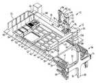
- the positioning device 10includes a gantry robot 12 and an elevator unit 14 .
- the positioning device 10is a modular, reconfigurable, and multi-functional robot designed for automatic picking/arraying/re-arraying/gridding/and microarraying of bacteria, yeast, or phage colonies or other biological samples.
- Pickingrefers to collecting randomly distributed samples from Petri plates and transferring the samples to microwell plates or other labware.
- Arrayingrefers to collecting the samples from microwell or gel plates and transferring the samples onto gel plates in an orderly fashion such as a matrix of spots or samples.
- Re-arrayingrefers to picking up selected individual colonies, and re-positioning them in a pre-defined order.
- Griddingrefers to collecting the samples form microwell plates and transferring the samples onto membranes.
- Microarrayingrefers to collecting the samples from the microwell plates and transferring the samples onto glass slides.
- Gantry robot 12has 3-degrees-of-freedom (3-dof) and elevator unit 14 has 1-degree of freedom (dof).
- the gantry robot 12provides a means for performing predetermined or programmed tasks within the work-space of the machine and the elevator unit 14 is used for storing and loading a plurality of holding plates called trays 16 .
- Each tray 16can hold/carry different number and type of labware.
- Gantry robot 12consists of an X linear actuator 18 , a Y linear actuator 20 and a Z linear actuator 22 . Each linear actuator is driven by a separate motor 24 , 26 and 28 respectively. Each motor provides linear motion for the head assembly 30 along its respective axis.
- a main plate 32is the structural base for the gantry robot 12 .
- the X linear actuator and the Y linear actuatordefine the work-space.
- Elevator unit 14is attached to main plate 32 with two side supports 34 .
- a back support 35is attached between the two supports 34 .
- the elevator unit 14is outside of but adjacent to the work-space.
- Side supports 34 and back support 35are stationary.
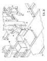
- An elevator linear actuator 36is attached to the back support 35 .
- An elevator motor 37is attached to linear actuator 36 and together they provide the up/down motion of a plurality of shelves 38 , shown here by way of example as four shelves.
- Each shelf 38includes a pair of side portions 39 connected to a common back portion 33 .
- Each side portion 39has an L-shaped support 41 attached thereto.
- the L-shaped support 41provides a ledge adapted to receive a tray 16 . Stoppers 43 , best seen in FIG.
- the elevator unit 14may include a refrigerator enclosure 55 as shown in FIG. 12 .
- an elevator X linear actuator 57may be used to push a tray inwardly toward the tray loader 94 , as shown in FIGS. 13 and 14.
- the trayneed only pushed inwardly enough to provide access to hole or depression 102 in tray 16 .
- the elevator X linear actuator 57is aligned with a tray 16 when it is pushed onto platform 46 .
- the elevator X linear actuatoris attached to back support 35 .
- X linear actuator 18 and a rail 40 parallel to the X linear actuator 18there is an X motor 24 , and X linear actuator 18 and a rail 40 parallel to the X linear actuator 18 .
- the X linear actuator 18 and the rail 40are spaced apart and are attached to the main plate 32 .
- the Y linear actuator 20is attached to a connecting plate 42 which extends between the X linear actuator 18 and the rail 40 .
- a spacer 44raises up connecting plate 42 so that it is level.
- Y motor 26moves head assembly 30 along the Y axis.
- Z motor 28 and Z linear actuator 22move the head assembly 30 up and down or along the Z axis.
- Main plate 32is divided into a plurality of areas. The number and function of the areas can be adapted by the user. In the embodiment shown in FIGS. 1 and 2, main plate 32 has two platforms 46 , a cleaning area 48 and a stacking area 50 .
- Each platform 46is dimensioned to hold one tray 16 . Since a tray has precisely defined dimensions, or the same footprint, any tray can be brought to the platform by sliding from right to left or removed from the platform by sliding from left to right along the X direction.
- a pair of rails 99are positioned on the platform 46 for receiving trays 16 .
- the gantry robot 12performs the sliding (storing and retrieving) of the trays to and from the elevator unit 14 .
- the pair of rods 98move along the X axis with the robot and thus can transfer a tray to and from the elevator by sliding.
- the rodsare actuated so that the rods can engage or release from the matching holes 102 in the trays.
- FIGS. 3 to 5Three examples of trays 16 are shown in FIGS. 3 to 5 . All trays 16 have the same external footprint (X and Y dimensions). However, different trays 16 are designed to hold different types of labware.
- a microwell plate holder tray 52is shown in FIG. 3 . Tray 52 is designed to hold up to 10 standard size microwell plates 54 , or other labware of a similar footprint. Tray 52 can be used for colony picking, colony arraying, liquid handling, re-arraying, gridding, and micro-arraying applications.
- Alternatively a Petri plate holder tray 56is shown in FIG. 4 . Tray 56 holds one large size Petri plate 58 (or omni-tray), and four standard microwell plates 54 . Tray 56 is typically used for colony-picking applications.
- FIG. 5Another alternative is shown in FIG. 5 and is a membrane holder tray 60 .
- Tray 60holds two large-size membranes 62 , or two large-size omni-trays. Tray 60 can be used for gridding applications. As can be seen from these examples the variety of tray types can be designed to hold special labware or other items for variety of applications as long as the trays have the predetermined foot print. Accordingly using different designs of trays, provides means for modularity, reconfigurability, and multi-functionality of positioning device 10 .
- the cleaning area 48includes a washing station 64 , a drying station 66 and a sonicator 68 .
- a washing station 64Preferably at least two types of wash stations are used, namely an automatic washing station, and a regular wash station.
- Automatic washing stationis attached to fill and drain pumps for automatic filling and emptying of the container.
- Up to three washing stations 64can be mounted in the cleaning area 48 .
- Each washing stationcan contain different type of wash solution.
- the designs of washing stationsare modular, such that they can be easily removed from the main plate 32 and replaced by other modules such as a microwell or tip-rack holders.
- the drying station 66generates a uniform flow of hot air for fast drying of the pins after washing.
- a sonicator or ultrasonic cleaneris mounted on the main plate 32 for better removal of residuals on the pins.
- the elements of the cleaning area 48are used for cleaning, sterilizing, and drying of pins and can be adapted because of the modularity to different types and sizes of pins that are utilized for different applications.
- the cleaning areacan be used for pins used for replicating, gridding, arraying, re-arraying, and picking of bacteria colonies.
- the stacking area 50has a plurality of stackers 70 .
- FIGS. 1 and 2show five stackers 70 .
- Each stacker 70is used for temporary storage of a plurality of plates 54 .
- Reusable packagescan be mounted on the stacking area for automatic packing and unpacking of several plates. Plates that are packed in a reusable package can be easily transferred to other places for subsequent processing.
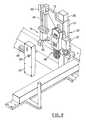
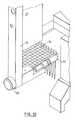
- Head assembly 30can have a plurality of tools attached to a Z plate 72 , for example a gripper 74 , a replicator 76 , a picker-head 78 or a pipettor 80 .
- a block 81is attached to Z plate 72 .
- Block 81as best seen in FIG. 7, has a plurality of holes 83 therein for receiving positioning pins 85 and attachment screws 87 that are used to position and attach tools to block 81 as best seen in FIG. 9 .
- Gripper 74includes a linear guide 82 , an actuator 84 and a claw 86 , as best seen in FIGS. 1 and 6.
- the gripper claw 86is actuated, opened and closed, by means of the actuator 84 .
- the gripper 74 shown hereinis adapted to grip microwell plates and all other labware with the same footprint.
- Gripper 74would by modified to grip Petri plates 58 and labware of varying foodprints.
- Gripper 74is used for automatic gripping and carrying of different labware from one place to another in the working area.
- a microwell plate 54can be carried from its position on a platform 46 to a stacker 70 .
- a replicator 76is attached to Z-plate 72 with screw 87 and a loading pin 77 .
- Replicator 76typically has 768, 384 or 96 pins.
- Replicator 76is for the simultaneous replication or arraying of 768 samples of bacteria, yeast, or other colonies.
- Picker-head 78includes a plurality of pins 88 as best seen in FIG. 6 and FIG. 7 .
- Each pin 88includes an actuator 90 such that it can be separately actuated.
- Actuator 90shown herein, is an air cylinder that moves the pin to the up or down position. In the example shown herein 16 pins are shown.
- Each pin 88is used to pick a sample of a randomly distributed bacterium (or other types of) colony from a growth media.
- Pipettor 80is used for accurate and automatic liquid transferring from one labware to another one as best seen in FIGS. 8 and 9.
- Pipettor 80is generally available for manual use and has been adapted to be attached to block 81 and operated by an actuator 89 .
- a wide range of liquid volumecan be transferred, e.g., from 0.1 micro-liter to 250 micro-liter or more.
- a novel design of the pipettorallows for quick attachment or removal.
- Pipettor 80can be quickly attached to and detached from block 81 and controlled by the control system. As discussed above the pipettor is attached such that the positioning pins 85 are in registration with corresponding holes 83 in block 81 and a screw 87 attaches it thereto.
- the actuator 89is used to automatically release the pipettor tips.
- the gripper 74 and camera 92are fixed to Z-plate 72 and the replicator 76 , picker head 78 and pipettor 80 are attachable to Z-plate 72 .
- the tray loader 94is attached to connecting plate 42 as described in more detail below.
- a CCD (charged coupled device) camera 92is attached to Z-plate 72 .
- Camera 92is operably connected to image processing software (not shown).
- Camera 92 in conjunction with the image processing softwareis used for the automatic recognition and classification of thousands of bacterium (or other types of) colonies.
- the X and Y coordinates of the classified coloniesare then precisely calculated by the image processing software and sent to robot controller (not shown) for automatic picking of the colonies.
- camera 92 and image processing softwaremay also be used to take images of yeast or other types of colonies for saving in a central database system for automatic tracking of samples in several stages of the experiments.
- a tray loader 94is attached to connecting plate 42 which connects the X-linear actuator to the parallel rail 40 .
- Tray loader 94includes a pair of rod supports 96 that extend outwardly from the connecting plate 42 and a pair of rods 98 that extend downwardly from the supports 96 .
- Each rod 98has a rod actuator 108 that causes the rods 98 to move from a down position to an up position or vice versa. In the down position the rods 98 engage a hole or depression 102 in the trays 16 (as best seen in FIGS. 3 to 5 ).
- Tray loaders 94are used for automatic loading of trays from the elevator unit 14 to one of the platforms 46 and for unloading of trays 16 from platforms 46 to an empty shelf of the elevator unit 14 .
- a bar code reader 104 shown in FIG. 15is installed on the machine for automatic reading, verification, and storage of bar code labels on microwell plates or other similar type of labware. Bar code reader 104 is attached to head assembly 30 .
- a controlled environmentmay be included below the elevator unit 14 such that environment for those trays that are not in use and are temporarily stored in the elevator unit may be controlled.
- the controlled environmentwould be enclosed and insulated and the temperature and humidity would be controlled. Therefore each time positioning device 10 completes the operations related to the two current trays on the platforms, the trays are loaded to the available bottom shelves of the elevator. Then, the elevator will move the two shelves down into the controlled environment.
- control systemincludes intelligent monitoring and data tracking subsystem. These subsystems use information from the artificial vision system and the automatic bar-code scanning system 104 .
- the vision systemincludes the camera 92 and the image processing software. Together the vision system and the bar-code scanning system 104 can automatically register and verify the current state of the samples each time they are used and processed on the device. The current state of the samples is determined by all relevant information obtained from the user and current and previous images of samples.
- the control systemincludes flexibility of software such that the user has full control on every task (or function) of the device.
- Each task (or function)means a specific operation performed by the device, for example, loading a tray from the elevator onto a platform.
- the tasksare categorized into two categories: 1) micro tasks, which consist of tasks for small and basic operations. Each micro task involves a few motions only, e.g., loading one tray from the elevator onto a platform, or removing the cover of a microwell plate; 2) macro tasks, which consist of tasks with many steps and several micro-tasks, e.g., packing eight microwell plates with their covers. All of the components are operably connected to a graphical user interface (GUI) to facilitate the use and operation of the positioning device 10 .
- GUIgraphical user interface
- An operational cycle for picking bacteria coloniesmay have the following steps:
- the userselects the number and types of trays required for the operation. For example, for colony picking the user may select two microwell trays 52 and two Petri plate trays 56 .
- the userfills the trays 52 , 56 with proper labware.
- the trays 52 , 56are loaded into elevators shelves 38 , with microwell tray 52 are loaded onto alternate shelves 38 and Petri plate trays 56 are loaded onto the free alternate shelves 38 of the elevator unit 14 .
- the wash stations 64 (FIG. 1) and the sonicator 68are filled with proper wash solutions.
- the required toolfor example a Picker Head 78 is attached to Z plate 72 .
- the userdefines all the tasks for this run (in this example, picking-up bacteria colonies from the square Petri plates on Petri plate trays 56 and transferring them to microwell plates 54 .
- the userruns the program.
- the machineautomatically performs the following steps:
- the camera 92scans the Petri plate 58 on Petri plate tray 56 .
- the image processing softwareautomatically finds the location of each bacteria colony, and categorizes the bacteria colonies into two groups of good and bad (based on their color, shape, proximity, size, etc.).
- the picker head 78picks up good bacteria colonies one by one. For example, a picker head with 16 pins can pick-up 16 colonies (one colony per pin). However, the sixteen colonies are picked up one-by-one in sixteen steps. At each step, one pin 88 moves down (while other 15 pins stay up) to pick up a specific colony.
- the sixteen picked up samplesare transferred to sixteen wells of a microwell plate 54 . If the microwell plate has a cover, the gripper 74 (FIG. 1) first removes the cover.
- the picker pins 88are washed, sterilized, and dried in the cleaning area (FIG. 2 ).
- the wash time and cycleare completely flexible and is determined by the user.
- Steps 4 to 6are repeated until all good colonies are picked up from the Petri plate and transferred to microwell plates.
- Positioning device 10can be used as an automatic colony picking device, which allows the user to pick up thousands of randomly distributed bacteria colonies (or other biological samples) from a growth media (e.g., a gel or agar plate), and transferring the colonies, in a proper order, to another growth media (e.g., a microwell plate). Bacteria colonies grow randomly on a gel plate, with different sizes, varying from 0.1 mm to few millimeters in diameter. Each colony must be first detected and precisely located, using an artificial vision system including the camera 92 and the image processing software.
- a growth mediae.g., a gel or agar plate
- Bacteria coloniesgrow randomly on a gel plate, with different sizes, varying from 0.1 mm to few millimeters in diameter. Each colony must be first detected and precisely located, using an artificial vision system including the camera 92 and the image processing software.
- the gantry robot 12moves the head assembly 30 to the colony position and with one of the tools picks up a sample and transfers it to a desired destination (typically a microwell plate 54 ). All stages of the process are performed automatically under control of a computerized control system.
- Positioning device 10can be used for automatic scanning gel plates, automatic gridding, automatic re-arraying or automatic super positioning.
- Automatic scanning of gel plates at different stages of a multi-stage biological process, using a high-resolution digital CCD camera 92includes processing the images of scanned plates using the image processing software and comparing the new images with the images from the previous stages of the biological process. The images and the processed information are then stored into a central database for subsequent retrieval and comparison.
- Automatic colony arrayingincludes the picking up an array of colonies (e.g., 768 colonies) simultaneously, and transferring all samples to a new gel plate, a microwell plate 52 or another growth media.
- Automatic griddingincludes picking up an array or an individual biological samples and spotting them (it) on a membrane 62 .
- Automatic re-arrayingincludes picking up selected individual colonies, and re-positioning them in a pre-defined order.
- Automatic super positioningincludes positioning one or more biological samples on one or more other biological samples for mating or other biological interactions.
- Positioning device 10can automatically change it's own configuration to perform variety of functions without any human intervention.
- the configuration of the positioning device 10is changed by loading and unloading different trays 16 form the elevator unit 14 and transferring plates for the trays to the stacking area 50 . Further, positioning device 10 can automatically pack and unpack different labware (e.g., microwell plates 54 ), into (and from) reusable stackers 70 .
- labwaree.g., microwell plates 54
- Positioning device 10provides for intelligent monitoring and data tracking which is based on the machine vision system (including the camera 92 ) and an automatic bar-code scanning system (including the bar code reader 104 ). Each plate is identified with a unique bar-code number, which is read automatically during the run, and compared with the stored information in the central database to avoid any possible mistake.
- Positioning device 10includes a packing/unpacking system that allows for automatic packing or unpacking of several microwell plates (or other similar labware) into or from reusable packages. Each package is used to transfer and process multiple plates (one batch of plates may contain eight or more plates) simultaneously. Each package or batch is labeled and identified by a bar-code label. Such an identification number allows for systematic storing, tracking, and retrieval of all the information related to that batch.
Landscapes
- Engineering & Computer Science (AREA)
- Chemical & Material Sciences (AREA)
- General Physics & Mathematics (AREA)
- Immunology (AREA)
- Life Sciences & Earth Sciences (AREA)
- Analytical Chemistry (AREA)
- Biochemistry (AREA)
- General Health & Medical Sciences (AREA)
- Physics & Mathematics (AREA)
- Health & Medical Sciences (AREA)
- Pathology (AREA)
- Robotics (AREA)
- Mechanical Engineering (AREA)
- Chemical Kinetics & Catalysis (AREA)
- Multimedia (AREA)
- Automatic Analysis And Handling Materials Therefor (AREA)
Abstract
Description
Claims (19)
Priority Applications (1)
| Application Number | Priority Date | Filing Date | Title |
|---|---|---|---|
| US09/667,670US6353774B1 (en) | 2000-09-22 | 2000-09-22 | High precision vision guided positioning device |
Applications Claiming Priority (1)
| Application Number | Priority Date | Filing Date | Title |
|---|---|---|---|
| US09/667,670US6353774B1 (en) | 2000-09-22 | 2000-09-22 | High precision vision guided positioning device |
Publications (1)
| Publication Number | Publication Date |
|---|---|
| US6353774B1true US6353774B1 (en) | 2002-03-05 |
Family
ID=24679144
Family Applications (1)
| Application Number | Title | Priority Date | Filing Date |
|---|---|---|---|
| US09/667,670Expired - Fee RelatedUS6353774B1 (en) | 2000-09-22 | 2000-09-22 | High precision vision guided positioning device |
Country Status (1)
| Country | Link |
|---|---|
| US (1) | US6353774B1 (en) |
Cited By (53)
| Publication number | Priority date | Publication date | Assignee | Title |
|---|---|---|---|---|
| US20020192716A1 (en)* | 1999-03-19 | 2002-12-19 | Volker Schellenberger | Multi-through hole testing plate for high throughput screening |
| US20030044991A1 (en)* | 2001-09-06 | 2003-03-06 | Genetix Limited | Apparatus for and methods of handling biological sample containers |
| US20030044321A1 (en)* | 2001-09-06 | 2003-03-06 | Haslam James Keith | Apparatus for and methods of handling biological sample containers |
| US20030048448A1 (en)* | 2001-03-19 | 2003-03-13 | Fleming Timothy J. | Automated apparatus for testing optical filters |
| US20040037748A1 (en)* | 2002-08-23 | 2004-02-26 | Leila Hasan | Voltage-aided transfer pins |
| USD487518S1 (en) | 2002-01-25 | 2004-03-09 | Robodesign International, Inc. | Micro-well plate storage tray |
| US20040123567A1 (en)* | 2002-08-07 | 2004-07-01 | Medco Health Solutions, Inc. | Automated container bulking system and method optionally integrated with automated dispensing system and/or automated labeling and packaging system |
| US20040191924A1 (en)* | 1998-01-12 | 2004-09-30 | Massachusetts Institute Of Technology | Reformatted through-hole arrays |
| US20040208792A1 (en)* | 2002-12-20 | 2004-10-21 | John Linton | Assay apparatus and method using microfluidic arrays |
| WO2005017785A1 (en)* | 2003-07-14 | 2005-02-24 | Cadence Design Systems, Inc. | Method for creating patterns for producing integrated circuits |
| US20050136534A1 (en)* | 2003-10-24 | 2005-06-23 | John Austin | Apparatus and method for dispensing fluid, semi-solid and solid samples |
| US20060105453A1 (en)* | 2004-09-09 | 2006-05-18 | Brenan Colin J | Coating process for microfluidic sample arrays |
| WO2006036307A3 (en)* | 2004-08-04 | 2006-08-17 | Biotrove Inc | Method and system for registering dispenser array location |
| WO2006121886A1 (en)* | 2005-05-06 | 2006-11-16 | Kalypsys, Inc. | Automated compound screening using gel-permeation matrix and pin-based sample transfer |
| WO2007017384A1 (en)* | 2005-08-05 | 2007-02-15 | Giuseppe Marcellino | Automatic analyzer for enzyme immunoassays |
| US20090117004A1 (en)* | 2007-11-06 | 2009-05-07 | Abbott Laboratories | System for automatically loading immunoassay analyzer |
| US20090181359A1 (en)* | 2007-10-25 | 2009-07-16 | Lou Sheng C | Method of performing ultra-sensitive immunoassays |
| US7604983B2 (en) | 2000-02-18 | 2009-10-20 | Board Of Trustees Of The Leland Stanford Junior University | Apparatus and methods for parallel processing of micro-volume liquid reactions |
| US20100199999A1 (en)* | 2009-02-06 | 2010-08-12 | Vazales Brad E | Methods for cleaning endotracheal tubes |
| US20110003699A1 (en)* | 2002-12-20 | 2011-01-06 | Biotrove, Inc. | Thermal Cycler for Microfluidic Array Assays |
| US20110023888A1 (en)* | 2009-02-06 | 2011-02-03 | Endoclear, Llc | Methods for removing debris from medical tubes |
| US8000837B2 (en)* | 2004-10-05 | 2011-08-16 | J&L Group International, Llc | Programmable load forming system, components thereof, and methods of use |
| US8105554B2 (en) | 2004-03-12 | 2012-01-31 | Life Technologies Corporation | Nanoliter array loading |
| WO2012055411A1 (en)* | 2010-10-29 | 2012-05-03 | Marel A/S | System for conveying batching means and for batching objects |
| CN103042523A (en)* | 2012-12-12 | 2013-04-17 | 浙江今跃机械科技开发有限公司 | Gantry robot |
| WO2013070744A3 (en)* | 2011-11-07 | 2014-01-03 | Beckman Coulter, Inc. | Specimen container detection |
| US8840848B2 (en) | 2010-07-23 | 2014-09-23 | Beckman Coulter, Inc. | System and method including analytical units |
| CN104316714A (en)* | 2014-11-18 | 2015-01-28 | 南京裕隆生物医学发展有限公司 | Sample releasing control device for sample releasing needle of full-automatic tube-type chemiluminescent analyzer |
| US8973736B2 (en) | 2011-11-07 | 2015-03-10 | Beckman Coulter, Inc. | Magnetic damping for specimen transport system |
| US9329194B2 (en) | 2007-11-05 | 2016-05-03 | Abbott Laboratories | Automated analyzer for clinical laboratory |
| US9335336B2 (en) | 2011-09-09 | 2016-05-10 | Gen-Probe Incorporated | Automated sample handling instrumentation, systems, processes, and methods |
| US9445714B2 (en) | 2010-03-29 | 2016-09-20 | Endoclear Llc | Endotracheal tube coupling adapters |
| US9446418B2 (en) | 2011-11-07 | 2016-09-20 | Beckman Coulter, Inc. | Robotic arm |
| US9482684B2 (en) | 2011-11-07 | 2016-11-01 | Beckman Coulter, Inc. | Centrifuge system and workflow |
| US9506943B2 (en) | 2011-11-07 | 2016-11-29 | Beckman Coulter, Inc. | Aliquotter system and workflow |
| CN104040353B (en)* | 2011-11-07 | 2016-11-30 | 贝克曼考尔特公司 | Sample container detects |
| CN106737864A (en)* | 2016-12-29 | 2017-05-31 | 上海大学 | A kind of Method of Calculation of Robotic Movements mechanism |
| WO2017157402A1 (en)* | 2016-03-17 | 2017-09-21 | Itu Business Development A/S | A robot and a method of controlling a robot |
| US9910054B2 (en) | 2011-11-07 | 2018-03-06 | Beckman Coulter, Inc. | System and method for processing samples |
| US10004863B2 (en) | 2012-12-04 | 2018-06-26 | Endoclear Llc | Closed suction cleaning devices, systems and methods |
| US10016575B2 (en) | 2014-06-03 | 2018-07-10 | Endoclear Llc | Cleaning devices, systems and methods |
| CN108504565A (en)* | 2017-02-27 | 2018-09-07 | 厦门鹭港兆康生物科技有限公司 | A kind of automatic positioning seeder |
| US10210607B1 (en) | 2015-04-08 | 2019-02-19 | Wein Holding LLC | Digital projection system and method for workpiece assembly |
| CN109773795A (en)* | 2019-03-15 | 2019-05-21 | 闽南理工学院 | An intelligent five-axis portal manipulator control system and method |
| US10427162B2 (en) | 2016-12-21 | 2019-10-01 | Quandx Inc. | Systems and methods for molecular diagnostics |
| CN111361917A (en)* | 2020-03-16 | 2020-07-03 | 福建通力达实业有限公司 | Method and system for measuring, calculating and correcting position of mobile shelf |
| US10712356B2 (en)* | 2015-04-21 | 2020-07-14 | General Automation Lab Technologies Inc. | Apparatus and method for picking biological sample |
| US10722322B2 (en) | 2010-03-29 | 2020-07-28 | Endoclear Llc | Distal airway cleaning devices |
| WO2021012687A1 (en)* | 2019-07-22 | 2021-01-28 | 北京极智嘉科技有限公司 | Sorting system and robot |
| CN113106006A (en)* | 2021-04-09 | 2021-07-13 | 江苏滋百农生态农业股份有限公司 | Functional bacterium quantitative determination arm |
| WO2021257895A1 (en)* | 2020-06-17 | 2021-12-23 | IAM Robotics, LLC | Bin retrieval and transport systems and methods |
| US20230028405A1 (en)* | 2019-12-18 | 2023-01-26 | Fondazione Istituto Italiano Di Tecnologia | Modular configurable robot, corresponding method and computer program product |
| US12070731B2 (en) | 2004-08-04 | 2024-08-27 | Life Technologies Corporation | Methods and systems for aligning dispensing arrays with microfluidic sample arrays |
Citations (7)
| Publication number | Priority date | Publication date | Assignee | Title |
|---|---|---|---|---|
| US4821408A (en)* | 1986-12-05 | 1989-04-18 | Gemcor Engineering Corp. | Programmable fixture and assembly cell |
| US5220718A (en)* | 1986-12-05 | 1993-06-22 | Gemcor Engineering Corp. | Programmable fixture and assembly cell |
| US5506682A (en)* | 1982-02-16 | 1996-04-09 | Sensor Adaptive Machines Inc. | Robot vision using targets |
| US5939022A (en)* | 1997-12-09 | 1999-08-17 | Pharmacia Biotech, Inc. | Article for transporting biological samples during analysis |
| US6201203B1 (en)* | 1999-05-12 | 2001-03-13 | Northrop Grumman Corporation | Robotic containerization system |
| US20010009136A1 (en)* | 1999-03-15 | 2001-07-26 | Pe Corporation (Ny) | Apparatus and method for spotting a substrate |
| US20010018216A1 (en)* | 1999-04-16 | 2001-08-30 | Pe Corporation (Ny) | Apparatus and method for transfering small volumes of substances |
- 2000
- 2000-09-22USUS09/667,670patent/US6353774B1/ennot_activeExpired - Fee Related
Patent Citations (8)
| Publication number | Priority date | Publication date | Assignee | Title |
|---|---|---|---|---|
| US5506682A (en)* | 1982-02-16 | 1996-04-09 | Sensor Adaptive Machines Inc. | Robot vision using targets |
| US4821408A (en)* | 1986-12-05 | 1989-04-18 | Gemcor Engineering Corp. | Programmable fixture and assembly cell |
| US5220718A (en)* | 1986-12-05 | 1993-06-22 | Gemcor Engineering Corp. | Programmable fixture and assembly cell |
| US5653005A (en)* | 1986-12-05 | 1997-08-05 | Gemcor Engineering Corp. | Programmable fixture and assembly cell |
| US5939022A (en)* | 1997-12-09 | 1999-08-17 | Pharmacia Biotech, Inc. | Article for transporting biological samples during analysis |
| US20010009136A1 (en)* | 1999-03-15 | 2001-07-26 | Pe Corporation (Ny) | Apparatus and method for spotting a substrate |
| US20010018216A1 (en)* | 1999-04-16 | 2001-08-30 | Pe Corporation (Ny) | Apparatus and method for transfering small volumes of substances |
| US6201203B1 (en)* | 1999-05-12 | 2001-03-13 | Northrop Grumman Corporation | Robotic containerization system |
Non-Patent Citations (4)
| Title |
|---|
| Bisiach et al., The adaptation of gantry-robot, operating in a Railway Industry Co., 1998, IEEE, pp. 2132-2136.* |
| Majors et al., Time-optimal transportation of flexible payloads, 1997, IEEE, pp. 3455-3460.* |
| Oh, Visual servoing by partitioning degrees of freedom, 2001, IEEE, pp. 1-17.* |
| Yang et al., H(sub infinity) Control design for positioning performance of gantry robots, 2000, IEEE, pp. 3038-3042.* |
Cited By (138)
| Publication number | Priority date | Publication date | Assignee | Title |
|---|---|---|---|---|
| US20040191924A1 (en)* | 1998-01-12 | 2004-09-30 | Massachusetts Institute Of Technology | Reformatted through-hole arrays |
| US20050079105A1 (en)* | 1998-01-12 | 2005-04-14 | Massachusetts Institute Of Technology | Methods for filing a sample array by droplet dragging |
| US7547556B2 (en) | 1998-01-12 | 2009-06-16 | Massachusetts Institute Of Technology | Methods for filing a sample array by droplet dragging |
| US8029745B2 (en) | 1998-01-12 | 2011-10-04 | Massachusetts Institute Of Technology | Systems for filling a sample array by droplet dragging |
| US7666360B2 (en) | 1999-03-19 | 2010-02-23 | Biotrove, Inc. | Multi-through hole testing plate for high throughput screening |
| US10195579B2 (en) | 1999-03-19 | 2019-02-05 | Life Technologies Corporation | Multi-through hole testing plate for high throughput screening |
| US20020192716A1 (en)* | 1999-03-19 | 2002-12-19 | Volker Schellenberger | Multi-through hole testing plate for high throughput screening |
| US8906618B2 (en) | 2000-02-18 | 2014-12-09 | The Board Of Trustees Of The Leland Stanford Junior University | Apparatus and methods for parallel processing of micro-volume liquid reactions |
| US10378049B2 (en) | 2000-02-18 | 2019-08-13 | The Board Of Trustees Of The Leland Stanford Junior University | Apparatus and methods for parallel processing of microvolume liquid reactions |
| US9518299B2 (en) | 2000-02-18 | 2016-12-13 | The Board Of Trustees Of The Leland Stanford Junior University | Apparatus and methods for parallel processing of micro-volume liquid reactions |
| US10227644B2 (en) | 2000-02-18 | 2019-03-12 | The Board Of Trustees Of The Leland Stanford Junior University | Apparatus and methods for parallel processing of microvolume liquid reactions |
| US7604983B2 (en) | 2000-02-18 | 2009-10-20 | Board Of Trustees Of The Leland Stanford Junior University | Apparatus and methods for parallel processing of micro-volume liquid reactions |
| US20030048448A1 (en)* | 2001-03-19 | 2003-03-13 | Fleming Timothy J. | Automated apparatus for testing optical filters |
| US6843962B2 (en)* | 2001-09-06 | 2005-01-18 | Genetix Limited | Apparatus for and methods of handling biological sample containers |
| US6998094B2 (en)* | 2001-09-06 | 2006-02-14 | Genetix Limited | Apparatus for and methods of handling biological sample containers |
| US20030044991A1 (en)* | 2001-09-06 | 2003-03-06 | Genetix Limited | Apparatus for and methods of handling biological sample containers |
| US20030044321A1 (en)* | 2001-09-06 | 2003-03-06 | Haslam James Keith | Apparatus for and methods of handling biological sample containers |
| USD487518S1 (en) | 2002-01-25 | 2004-03-09 | Robodesign International, Inc. | Micro-well plate storage tray |
| US7530211B2 (en)* | 2002-08-07 | 2009-05-12 | Medco Health Solutions, Inc. | System for emptying pharmaceutical containers |
| US8117809B2 (en) | 2002-08-07 | 2012-02-21 | Medco Health Solutions, Inc. | System for emptying pharmaceutical containers |
| US20090211198A1 (en)* | 2002-08-07 | 2009-08-27 | Medco Health Solutions, Inc. | Automated container bulking system and method optionally integrated with automated dispensing system and/or automated labeling and packaging system |
| US20040123567A1 (en)* | 2002-08-07 | 2004-07-01 | Medco Health Solutions, Inc. | Automated container bulking system and method optionally integrated with automated dispensing system and/or automated labeling and packaging system |
| US20090054266A1 (en)* | 2002-08-23 | 2009-02-26 | Biotrove, Inc. | Microfluidic transfer pin |
| US20040037748A1 (en)* | 2002-08-23 | 2004-02-26 | Leila Hasan | Voltage-aided transfer pins |
| US8277753B2 (en) | 2002-08-23 | 2012-10-02 | Life Technologies Corporation | Microfluidic transfer pin |
| US8685340B2 (en) | 2002-08-23 | 2014-04-01 | Life Technologies Corporation | Microfluidic transfer pin |
| US7682565B2 (en) | 2002-12-20 | 2010-03-23 | Biotrove, Inc. | Assay apparatus and method using microfluidic arrays |
| US8697452B2 (en) | 2002-12-20 | 2014-04-15 | Life Technologies Corporation | Thermal cycling assay apparatus and method |
| US9428800B2 (en) | 2002-12-20 | 2016-08-30 | Life Technologies Corporation | Thermal cycling apparatus and method |
| US20040208792A1 (en)* | 2002-12-20 | 2004-10-21 | John Linton | Assay apparatus and method using microfluidic arrays |
| US20090062152A1 (en)* | 2002-12-20 | 2009-03-05 | Biotrove, Inc. | Thermal cycling apparatus and method |
| US20090062134A1 (en)* | 2002-12-20 | 2009-03-05 | Biotrove, Inc. | Assay imaging apparatus and methods |
| US20110003699A1 (en)* | 2002-12-20 | 2011-01-06 | Biotrove, Inc. | Thermal Cycler for Microfluidic Array Assays |
| WO2005017785A1 (en)* | 2003-07-14 | 2005-02-24 | Cadence Design Systems, Inc. | Method for creating patterns for producing integrated circuits |
| US7585463B2 (en) | 2003-10-24 | 2009-09-08 | Aushon Biosystems, Inc. | Apparatus and method for dispensing fluid, semi-solid and solid samples |
| US20050136534A1 (en)* | 2003-10-24 | 2005-06-23 | John Austin | Apparatus and method for dispensing fluid, semi-solid and solid samples |
| US9527085B2 (en) | 2003-10-24 | 2016-12-27 | Aushon Biosystems, Inc. | Apparatus and method for dispensing fluid, semi-solid and solid samples |
| US10974247B2 (en) | 2004-03-12 | 2021-04-13 | Life Technologies Corporation | Nanoliter array loading |
| US10065189B2 (en) | 2004-03-12 | 2018-09-04 | Life Technologies Corporation | Nanoliter array loading |
| US8545772B2 (en) | 2004-03-12 | 2013-10-01 | Life Technologies Corporation | Nanoliter array loading |
| US9266108B2 (en) | 2004-03-12 | 2016-02-23 | Life Technologies Corporation | Nanoliter array loading |
| US8105554B2 (en) | 2004-03-12 | 2012-01-31 | Life Technologies Corporation | Nanoliter array loading |
| WO2006036307A3 (en)* | 2004-08-04 | 2006-08-17 | Biotrove Inc | Method and system for registering dispenser array location |
| US11154834B2 (en) | 2004-08-04 | 2021-10-26 | Life Technologies Corporation | Coating process for microfluidic sample arrays |
| US12070731B2 (en) | 2004-08-04 | 2024-08-27 | Life Technologies Corporation | Methods and systems for aligning dispensing arrays with microfluidic sample arrays |
| EP1782075B1 (en)* | 2004-08-04 | 2023-10-04 | Life Technologies Corporation | Method for differentially coating a substrate |
| US10213761B2 (en) | 2004-08-04 | 2019-02-26 | Life Technologies Corporation | Coating process for microfluidic sample arrays |
| US20060105453A1 (en)* | 2004-09-09 | 2006-05-18 | Brenan Colin J | Coating process for microfluidic sample arrays |
| US8000837B2 (en)* | 2004-10-05 | 2011-08-16 | J&L Group International, Llc | Programmable load forming system, components thereof, and methods of use |
| WO2006121886A1 (en)* | 2005-05-06 | 2006-11-16 | Kalypsys, Inc. | Automated compound screening using gel-permeation matrix and pin-based sample transfer |
| US20080206855A1 (en)* | 2005-05-06 | 2008-08-28 | Kalypsys, Inc. | Automated Compound Screening Using Gel-Permeation Matrix and Pin-Based Sample Transfer |
| WO2007017384A1 (en)* | 2005-08-05 | 2007-02-15 | Giuseppe Marcellino | Automatic analyzer for enzyme immunoassays |
| US20090150081A1 (en)* | 2005-08-05 | 2009-06-11 | Giuseppe Marcellino | Automatic analyzer for enzyme immunoassays |
| US20090181359A1 (en)* | 2007-10-25 | 2009-07-16 | Lou Sheng C | Method of performing ultra-sensitive immunoassays |
| US9329194B2 (en) | 2007-11-05 | 2016-05-03 | Abbott Laboratories | Automated analyzer for clinical laboratory |
| US20090117004A1 (en)* | 2007-11-06 | 2009-05-07 | Abbott Laboratories | System for automatically loading immunoassay analyzer |
| WO2009061643A1 (en)* | 2007-11-06 | 2009-05-14 | Abbott Laboratories | System for automatically loading laboratory analyzer |
| US8691149B2 (en) | 2007-11-06 | 2014-04-08 | Abbott Laboratories | System for automatically loading immunoassay analyzer |
| US9962233B2 (en) | 2009-02-06 | 2018-05-08 | Endoclear Llc | Body-inserted tube cleaning |
| US20110023886A1 (en)* | 2009-02-06 | 2011-02-03 | Endoclear, Llc | Medical tube cleaning apparatus |
| US20110023887A1 (en)* | 2009-02-06 | 2011-02-03 | Endoclear, Llc | Methods for tracheostomy visualization |
| US8601633B2 (en) | 2009-02-06 | 2013-12-10 | Endoclear Llc | Cleaning of body-inserted medical tubes |
| US10682203B2 (en) | 2009-02-06 | 2020-06-16 | Endoclear Llc | Methods of cleaning endotracheal tubes including light treatment |
| US10441380B2 (en) | 2009-02-06 | 2019-10-15 | Endoclear Llc | Body-inserted tube cleaning |
| US8534287B2 (en) | 2009-02-06 | 2013-09-17 | Endoclear, Llc | Methods for tracheostomy visualization |
| US8468637B2 (en) | 2009-02-06 | 2013-06-25 | Endoclear Llc | Mechanically-actuated endotracheal tube cleaning device |
| US8458844B2 (en) | 2009-02-06 | 2013-06-11 | Endoclear, Llc | Medical tube cleaning apparatus |
| US8382908B2 (en) | 2009-02-06 | 2013-02-26 | Endoclear, Llc | Methods for cleaning endotracheal tubes |
| US8381345B2 (en) | 2009-02-06 | 2013-02-26 | Endoclear, Llc | Devices for cleaning endotracheal tubes |
| US20100199448A1 (en)* | 2009-02-06 | 2010-08-12 | Endoclear, Llc | Devices for cleaning endotracheal tubes |
| US9095286B2 (en) | 2009-02-06 | 2015-08-04 | Endoclear Llc | Body-inserted tube cleaning |
| US20100199999A1 (en)* | 2009-02-06 | 2010-08-12 | Vazales Brad E | Methods for cleaning endotracheal tubes |
| US9907624B2 (en) | 2009-02-06 | 2018-03-06 | Endoclear Llc | Body-inserted tube cleaning with suction |
| US8157919B2 (en) | 2009-02-06 | 2012-04-17 | Endoclear, Llc | Methods for removing debris from medical tubes |
| US9855111B2 (en) | 2009-02-06 | 2018-01-02 | Endoclear Llc | Methods of removing biofilm from endotracheal tubes |
| US9579012B2 (en) | 2009-02-06 | 2017-02-28 | Endoclear Llc | Visualized endotracheal tube placement systems |
| US20110023888A1 (en)* | 2009-02-06 | 2011-02-03 | Endoclear, Llc | Methods for removing debris from medical tubes |
| US20110023885A1 (en)* | 2009-02-06 | 2011-02-03 | Endoclear, Llc | Mechanically-actuated endotracheal tube cleaning device |
| US9332891B2 (en) | 2009-02-06 | 2016-05-10 | Endoclear Llc | Tracheostomy visualization |
| US9386907B2 (en) | 2009-02-06 | 2016-07-12 | Endoclear Llc | Visualization systems and methods |
| US9398837B2 (en) | 2009-02-06 | 2016-07-26 | Endoclear Llc | Methods for confirming placement of endotracheal tubes |
| US10722322B2 (en) | 2010-03-29 | 2020-07-28 | Endoclear Llc | Distal airway cleaning devices |
| US9445714B2 (en) | 2010-03-29 | 2016-09-20 | Endoclear Llc | Endotracheal tube coupling adapters |
| US9046455B2 (en) | 2010-07-23 | 2015-06-02 | Beckman Coulter, Inc. | System and method including multiple processing lanes executing processing protocols |
| US8996320B2 (en) | 2010-07-23 | 2015-03-31 | Beckman Coulter, Inc. | System and method including analytical units |
| US8840848B2 (en) | 2010-07-23 | 2014-09-23 | Beckman Coulter, Inc. | System and method including analytical units |
| US8956570B2 (en) | 2010-07-23 | 2015-02-17 | Beckman Coulter, Inc. | System and method including analytical units |
| US9519000B2 (en) | 2010-07-23 | 2016-12-13 | Beckman Coulter, Inc. | Reagent cartridge |
| US8962308B2 (en) | 2010-07-23 | 2015-02-24 | Beckman Coulter, Inc. | System and method including thermal cycler modules |
| US8932541B2 (en) | 2010-07-23 | 2015-01-13 | Beckman Coulter, Inc. | Pipettor including compliant coupling |
| US9285382B2 (en) | 2010-07-23 | 2016-03-15 | Beckman Coulter, Inc. | Reaction vessel |
| US9140715B2 (en) | 2010-07-23 | 2015-09-22 | Beckman Coulter, Inc. | System and method for controlling thermal cycler modules |
| US9274132B2 (en) | 2010-07-23 | 2016-03-01 | Beckman Coulter, Inc. | Assay cartridge with reaction well |
| WO2012055411A1 (en)* | 2010-10-29 | 2012-05-03 | Marel A/S | System for conveying batching means and for batching objects |
| US10132821B2 (en) | 2011-09-09 | 2018-11-20 | Gen-Probe Incorporated | Automated method for determining the presence of a mucoid strand |
| US11815522B2 (en) | 2011-09-09 | 2023-11-14 | Gen-Probe Incorporated | Automated sample handing instrumentation, systems, processes, and methods |
| US11614454B2 (en) | 2011-09-09 | 2023-03-28 | Gen-Probe Incorporated | Automated container capping/decapping mechanism |
| US10877057B2 (en) | 2011-09-09 | 2020-12-29 | Gen-Probe Incorporated | Thermal printing on wall of tubular vessel |
| US10921338B2 (en) | 2011-09-09 | 2021-02-16 | Gen-Probe Incorporated | Sample container handling with automated cap removal/replacement and drip control |
| US9335336B2 (en) | 2011-09-09 | 2016-05-10 | Gen-Probe Incorporated | Automated sample handling instrumentation, systems, processes, and methods |
| CN104040353A (en)* | 2011-11-07 | 2014-09-10 | 贝克曼考尔特公司 | Specimen container detection |
| US8973736B2 (en) | 2011-11-07 | 2015-03-10 | Beckman Coulter, Inc. | Magnetic damping for specimen transport system |
| US9046506B2 (en) | 2011-11-07 | 2015-06-02 | Beckman Coulter, Inc. | Specimen container detection |
| US9506943B2 (en) | 2011-11-07 | 2016-11-29 | Beckman Coulter, Inc. | Aliquotter system and workflow |
| WO2013070744A3 (en)* | 2011-11-07 | 2014-01-03 | Beckman Coulter, Inc. | Specimen container detection |
| CN104040353B (en)* | 2011-11-07 | 2016-11-30 | 贝克曼考尔特公司 | Sample container detects |
| US9482684B2 (en) | 2011-11-07 | 2016-11-01 | Beckman Coulter, Inc. | Centrifuge system and workflow |
| US10048284B2 (en) | 2011-11-07 | 2018-08-14 | Beckman Coulter, Inc. | Sample container cap with centrifugation status indicator device |
| US9446418B2 (en) | 2011-11-07 | 2016-09-20 | Beckman Coulter, Inc. | Robotic arm |
| US10274505B2 (en) | 2011-11-07 | 2019-04-30 | Beckman Coulter, Inc. | Robotic arm |
| US9910054B2 (en) | 2011-11-07 | 2018-03-06 | Beckman Coulter, Inc. | System and method for processing samples |
| US11173266B2 (en) | 2012-12-04 | 2021-11-16 | Endoclear Llc | Closed suction cleaning devices, systems and methods |
| US10004863B2 (en) | 2012-12-04 | 2018-06-26 | Endoclear Llc | Closed suction cleaning devices, systems and methods |
| US10821249B2 (en) | 2012-12-04 | 2020-11-03 | Endoclear Llc | Closed suction cleaning devices, systems and methods |
| CN103042523A (en)* | 2012-12-12 | 2013-04-17 | 浙江今跃机械科技开发有限公司 | Gantry robot |
| US10850062B2 (en) | 2014-06-03 | 2020-12-01 | Endoclear Llc | Cleaning devices, systems and methods |
| US10016575B2 (en) | 2014-06-03 | 2018-07-10 | Endoclear Llc | Cleaning devices, systems and methods |
| CN104316714A (en)* | 2014-11-18 | 2015-01-28 | 南京裕隆生物医学发展有限公司 | Sample releasing control device for sample releasing needle of full-automatic tube-type chemiluminescent analyzer |
| CN104316714B (en)* | 2014-11-18 | 2015-10-14 | 南京裕隆生物医学发展有限公司 | A kind of Full-automatic tube-type chemiluminescent analyzer setting-out pin lofting control device |
| US10210607B1 (en) | 2015-04-08 | 2019-02-19 | Wein Holding LLC | Digital projection system and method for workpiece assembly |
| US10706532B1 (en) | 2015-04-08 | 2020-07-07 | Wein Holding LLC | Digital projection system for workpiece assembly and associated method |
| US11087457B1 (en) | 2015-04-08 | 2021-08-10 | Wein Holding LLC | Digital projection system and associated method |
| US10712356B2 (en)* | 2015-04-21 | 2020-07-14 | General Automation Lab Technologies Inc. | Apparatus and method for picking biological sample |
| WO2017157402A1 (en)* | 2016-03-17 | 2017-09-21 | Itu Business Development A/S | A robot and a method of controlling a robot |
| DK201670155A1 (en)* | 2016-03-17 | 2017-10-02 | Itu Business Dev As | A robot and a method of controlling a robot |
| DK179325B1 (en)* | 2016-03-17 | 2018-04-30 | Itu Business Dev A/S | A robot and a method of controlling a robot |
| US10702990B2 (en) | 2016-03-17 | 2020-07-07 | Flow Robotics A/S | Robot and a method of controlling a robot |
| US10427162B2 (en) | 2016-12-21 | 2019-10-01 | Quandx Inc. | Systems and methods for molecular diagnostics |
| CN106737864A (en)* | 2016-12-29 | 2017-05-31 | 上海大学 | A kind of Method of Calculation of Robotic Movements mechanism |
| CN106737864B (en)* | 2016-12-29 | 2019-06-04 | 上海大学 | A Positive Solution Mechanism for Robot Kinematics |
| CN108504565A (en)* | 2017-02-27 | 2018-09-07 | 厦门鹭港兆康生物科技有限公司 | A kind of automatic positioning seeder |
| CN109773795A (en)* | 2019-03-15 | 2019-05-21 | 闽南理工学院 | An intelligent five-axis portal manipulator control system and method |
| WO2021012687A1 (en)* | 2019-07-22 | 2021-01-28 | 北京极智嘉科技有限公司 | Sorting system and robot |
| US20230028405A1 (en)* | 2019-12-18 | 2023-01-26 | Fondazione Istituto Italiano Di Tecnologia | Modular configurable robot, corresponding method and computer program product |
| US12109695B2 (en)* | 2019-12-18 | 2024-10-08 | Fondazione Istituto Italiano Di Tecnologia | Modular configurable robot, corresponding method and computer program product |
| CN111361917A (en)* | 2020-03-16 | 2020-07-03 | 福建通力达实业有限公司 | Method and system for measuring, calculating and correcting position of mobile shelf |
| WO2021257895A1 (en)* | 2020-06-17 | 2021-12-23 | IAM Robotics, LLC | Bin retrieval and transport systems and methods |
| CN113106006A (en)* | 2021-04-09 | 2021-07-13 | 江苏滋百农生态农业股份有限公司 | Functional bacterium quantitative determination arm |
Similar Documents
| Publication | Publication Date | Title |
|---|---|---|
| US6353774B1 (en) | High precision vision guided positioning device | |
| US12228483B2 (en) | System and method for the automated preparation of biological samples | |
| US12258212B2 (en) | Robotic processing system | |
| US12427546B2 (en) | System and method for robotic horizontal sortation | |
| US8865474B2 (en) | Automated laboratory system | |
| US7364907B2 (en) | Systems and methods for sorting samples | |
| WO2004026697A2 (en) | System and method of storing and retrieving storage elements | |
| JP2022518101A (en) | Process module for automated biological systems | |
| WO2001057539A1 (en) | Pipetting station apparatus | |
| JP7629057B2 (en) | Module for an automated biological laboratory system with an interface for transferring microplates or labware - Patent application | |
| CN102985978A (en) | Bulk transfer of storage devices using manual loading | |
| EP1573340A1 (en) | An automatic storage device with a cylindrical rack | |
| JP6527177B2 (en) | Automated sample processing system and method | |
| WO2000066467A1 (en) | Plate stacker apparatus | |
| JP2022516833A (en) | Labware and labware handling systems in cell culture processes | |
| US12385941B2 (en) | Automatic assaying system and methods therefor | |
| JP2023004755A (en) | Handling system, instruction device, handling method, program, and storage medium | |
| CN115917328A (en) | Method and apparatus for scanning a slide using at least two slide scanners | |
| EP1477813B1 (en) | Vial transfer apparatus | |
| US11796551B2 (en) | Centralized terminal | |
| WO2023062236A1 (en) | Distributed slide scanning system and method of operating a distributed slide scanning system | |
| CN219792975U (en) | Automatic bacterial colony culture counting system | |
| US20250027961A1 (en) | System and method for the automated preparation of biological samples | |
| US20250187201A1 (en) | Mobile robotic processing station, processing system, and method therefor | |
| Jaklevic et al. | Application of robotics and automation in a genomic laboratory |
Legal Events
| Date | Code | Title | Description |
|---|---|---|---|
| AS | Assignment | Owner name:VIRTEK BIOTECH CANADA INC., CANADA Free format text:MERGER;ASSIGNOR:VIRTEK ENGINEERING SCIENCES INC.;REEL/FRAME:013000/0863 Effective date:20020131 | |
| AS | Assignment | Owner name:BIO-RAD LABORATORIES (CANADA) LIMITED, CANADA Free format text:ASSIGNMENT OF ASSIGNORS INTEREST;ASSIGNOR:VIRTEK BIOTECH CANADA INC.;REEL/FRAME:013269/0184 Effective date:20020628 | |
| FEPP | Fee payment procedure | Free format text:PAYOR NUMBER ASSIGNED (ORIGINAL EVENT CODE: ASPN); ENTITY STATUS OF PATENT OWNER: LARGE ENTITY Free format text:PAT HOLDER NO LONGER CLAIMS SMALL ENTITY STATUS, ENTITY STATUS SET TO UNDISCOUNTED (ORIGINAL EVENT CODE: STOL); ENTITY STATUS OF PATENT OWNER: LARGE ENTITY | |
| REFU | Refund | Free format text:REFUND - SURCHARGE, PETITION TO ACCEPT PYMT AFTER EXP, UNINTENTIONAL (ORIGINAL EVENT CODE: R2551); ENTITY STATUS OF PATENT OWNER: LARGE ENTITY | |
| FPAY | Fee payment | Year of fee payment:4 | |
| FEPP | Fee payment procedure | Free format text:PAYOR NUMBER ASSIGNED (ORIGINAL EVENT CODE: ASPN); ENTITY STATUS OF PATENT OWNER: LARGE ENTITY Free format text:PAYER NUMBER DE-ASSIGNED (ORIGINAL EVENT CODE: RMPN); ENTITY STATUS OF PATENT OWNER: LARGE ENTITY | |
| REMI | Maintenance fee reminder mailed | ||
| LAPS | Lapse for failure to pay maintenance fees | ||
| STCH | Information on status: patent discontinuation | Free format text:PATENT EXPIRED DUE TO NONPAYMENT OF MAINTENANCE FEES UNDER 37 CFR 1.362 | |
| FP | Lapsed due to failure to pay maintenance fee | Effective date:20100305 |