US6353636B1 - Symbol alignment method - Google Patents
Symbol alignment methodDownload PDFInfo
- Publication number
- US6353636B1 US6353636B1US09/219,005US21900598AUS6353636B1US 6353636 B1US6353636 B1US 6353636B1US 21900598 AUS21900598 AUS 21900598AUS 6353636 B1US6353636 B1US 6353636B1
- Authority
- US
- United States
- Prior art keywords
- receiver window
- alignment
- receiver
- carrier frequency
- alignments
- Prior art date
- Legal status (The legal status is an assumption and is not a legal conclusion. Google has not performed a legal analysis and makes no representation as to the accuracy of the status listed.)
- Expired - Lifetime
Links
- 238000000034methodMethods0.000titleclaimsabstractdescription34
- 238000004891communicationMethods0.000claimsabstractdescription20
- 230000003595spectral effectEffects0.000claimsabstractdescription15
- 230000005540biological transmissionEffects0.000claimsdescription12
- 239000000969carrierSubstances0.000description40
- 238000005070samplingMethods0.000description16
- 238000005259measurementMethods0.000description5
- 238000012549trainingMethods0.000description4
- 230000000694effectsEffects0.000description3
- 238000011084recoveryMethods0.000description2
- 238000001228spectrumMethods0.000description2
- 238000012935AveragingMethods0.000description1
- RYGMFSIKBFXOCR-UHFFFAOYSA-NCopperChemical compound[Cu]RYGMFSIKBFXOCR-UHFFFAOYSA-N0.000description1
- 238000013459approachMethods0.000description1
- 239000002131composite materialSubstances0.000description1
- 229910052802copperInorganic materials0.000description1
- 239000010949copperSubstances0.000description1
- 230000001934delayEffects0.000description1
- 230000003111delayed effectEffects0.000description1
- 230000001419dependent effectEffects0.000description1
- 238000001514detection methodMethods0.000description1
- 238000011161developmentMethods0.000description1
- 230000018109developmental processEffects0.000description1
- 238000010586diagramMethods0.000description1
- 238000000605extractionMethods0.000description1
- 239000000203mixtureSubstances0.000description1
- 238000012545processingMethods0.000description1
- 230000006798recombinationEffects0.000description1
- 238000005215recombinationMethods0.000description1
Images


Classifications
- H—ELECTRICITY
- H04—ELECTRIC COMMUNICATION TECHNIQUE
- H04L—TRANSMISSION OF DIGITAL INFORMATION, e.g. TELEGRAPHIC COMMUNICATION
- H04L27/00—Modulated-carrier systems
- H04L27/26—Systems using multi-frequency codes
- H04L27/2601—Multicarrier modulation systems
- H04L27/2647—Arrangements specific to the receiver only
- H04L27/2655—Synchronisation arrangements
- H04L27/2662—Symbol synchronisation
- H—ELECTRICITY
- H04—ELECTRIC COMMUNICATION TECHNIQUE
- H04L—TRANSMISSION OF DIGITAL INFORMATION, e.g. TELEGRAPHIC COMMUNICATION
- H04L27/00—Modulated-carrier systems
- H04L27/26—Systems using multi-frequency codes
- H04L27/2601—Multicarrier modulation systems
- H04L27/2647—Arrangements specific to the receiver only
- H04L27/2655—Synchronisation arrangements
- H04L27/2668—Details of algorithms
- H04L27/2673—Details of algorithms characterised by synchronisation parameters
- H04L27/2676—Blind, i.e. without using known symbols
- H04L27/2679—Decision-aided
Definitions
- the present inventionrelates to a method and apparatus for determining symbol alignment in Discrete Multi-Tone (DMT) or similar communications systems and a system incorporating the same.
- DMTDiscrete Multi-Tone
- Telecommunication systemsthat interconnect wireline subscriber terminals are being developed to support broadband data communication. More particularly, recent developments in broadband communications protocols allow broadband data to be overlaid on narrowband voice or integrated service digital network (ISDN) traffic. Specifically, the interconnection of broadband modems located at the subscriber terminal and at an exchange allow current broadband access systems to communicate on spare spectrum (i.e. spare frequency channels) of a twisted pair communication resource; the spare frequency channels being isolated from conventionally encoded voice signals by a suitable filter.
- spare spectrumi.e. spare frequency channels
- overlaid broadband systemscan support data rates in excess of two Megabits per second (Mbps), although this rate is dependent upon the physical parameters of the connection, e.g. the overall length of the twisted pair and its composition and configuration.
- Asymmetric Digital Subscriber Line (ADSL) and High-Speed digital Subscriber Line (HDSL) protocolscan support data rates of 2 Mbps over distances of approximately three kilometres, while more complex schemes (such as VDSL) can support data rates of 8 Mbps and above over distances of, typically, less than two kilometres.
- Protocolssuch as Very high-speed Digital Subscriber Line (VDSL) utilise multiple sub-channel carriers, e.g. in a discrete multi-tone (DMT) environment, to provide a system that mitigates the effects of cross-talk by selectively ignoring noise-affected sub-channel carriers or reducing the number of bits supported on each sub-channel.
- DMTprovides a comb of frequency carriers that are each separately modulated and then combined to generate a composite signal envelope. As such, information (both control information and traffic) is distributed across a number of different frequency carriers.
- DMT schemes for supporting VDSLare often realised in a time division duplex (TDD) transmission environment in which a single communication resource (i.e. a frequency band) supports both up-link and down-link transmissions using the same frequencies.
- TDDtime division duplex
- a single communication resourcei.e. a frequency band
- the use of guard periods between adjacent groups of time-slots within a TDD frameensures that rogue overlapping transmissions within the up-link and down-link do not occur, and hence eliminates the likelihood of near-end cross talk (NEXT).
- NXTnear-end cross talk
- synchronisationis required to demodulate encoded signals that are addressed to the receiver.
- a pilot carrier or toneis used in a training sequence on a dedicated (pre-allocated) sub-channel. Initially, upon receipt of the pilot tone, the receiver acquires frequency lock and then establishes phase lock.
- the inventionseeks to provide an improved method and apparatus for determining symbol alignment in discrete multi-tone communications systems and a system incorporating the same.
- a method of determining symbol alignment in a discrete multi-tone communications systemcomprising the steps of: receiving a signal on each of at least one selected carrier frequency; for each of a plurality of receiver window alignments with respect to said signals, deriving a measure of received signal power level on each said selected carrier frequency; for each said receiver window alignment and selected carrier frequency deriving a measure of spectral leakage on at least one adjacent carrier frequency; selecting a receiver window alignment responsive to said derived measures.
- thisenables faster and more accurate selection of a receiver window alignment for symbol extraction than making the selection based on the power levels of the selected carrier frequency alone.
- the use of a power measurement on said selected carriers and said adjacent carriersprovides a more selective metric for the symbol alignment process than is obtained from a power measurement on said selected carrier frequency alone.
- said at least one adjacent carrier frequencyis a silent carrier frequency.
- silent carrier power levelsare at least in the order of 30 dB lower than active carrier power levels.
- said selection of receiver window alignmentis responsive to the difference between the received signal power level on said selected carrier frequency and a multiple of said received signal power level on said adjacent carrier frequencies
- said multipleis in the order of 50.
- each said measure of received signal power levelsis a time average of a plurality of measures of received signal power levels.
- thisprovides a more representative carrier power measurement and hence improves the reliability of the received symbol alignment.
- said selected receiver window alignmentis one of said set of receiver window alignments.
- said selected receiver alignment windowis interpolated between alignments in said set of receiver window alignments.
- thispermits use of a smaller number of receiver window alignments during sampling whilst still obtaining a well-positioned receiver window alignment.
- said carrier frequenciesare in a frequency band 0-10 MHz.
- thispermits the method to be used over existing twisted copper pair to the home.
- successive selected carrier frequenciesare separated by a plurality of silent carrier frequencies.
- selected carrier frequenciesare distributed across a frequency band utilised by said discrete multi-tone communications system.
- thisassists both in selecting a compromise symbol alignment suitable for all discrete frequencies in the frequency band, and in reducing the susceptibility to locally poor signal to noise ratio in any individual frequency.
- the step of selecting a receiver window alignment responsive to said derived measurescomprises the steps of: identifying which receiver window alignment gives rise to the largest difference; searching backwards and forwards to identify receiver window alignments at which said differences drop below a given fraction of said largest difference; selecting an optimal receiver window alignment between said receiver window alignments at which said differences drop below a given fraction of said largest difference.
- thiscompensates for cases where the largest difference may be unduly influenced by received noise which would give rise to a suboptimal choice of alignment.
- said receiver window alignment between said receiver window alignmentsis chosen to be approximately mid-way between said receiver window alignments at which said differences drop below a given fraction of said largest difference.
- said fractionis approximately nine tenths.
- said signalforms part of a TDD communications channel comprising a succession of frames, each frame comprising a receive region and each comprising a succession of DMT symbols.
- said step of deriving measures of received signal power level on each of said selected carrier frequenciesis performed on a single symbol in each said receive region.
- the step of selecting a receiver window alignment responsive to said derived measurescomprises the steps of: selecting a narrower range of receiver window alignments responsive to said derived measures; selecting, within said narrower range, a second range of receiver window alignments with respect to said signals; for each said receiver window alignment in said second range deriving a further measure of received signal power level on each said selected carrier frequency; for each said receiver window alignment in said second range and selected carrier frequency deriving a further measure of spectral leakage on at least one adjacent carrier frequency; selecting a receiver window alignment responsive to said further derived measures.
- the approach of performing a coarse grained alignment followed by a finer grained alignmentmay be used to speed up the alignment process.
- a signal receiverarranged to receive discrete multi-tone signals and comprising: a signal input arranged to receive a signal on each of at least one selected carrier frequency; a processor arranged to select a plurality of receiver window alignments with respect to said signals, for each said receiver window alignment to derive a measure of received signal power level on each said selected carrier frequency, for each said receiver window alignment and selected carrier frequency to derive a measure of spectral leakage on at least one adjacent carrier frequency and to select a receiver window alignment responsive to said derived measures.
- the inventionalso relates to a discrete multi-tone system comprising: a receiver according to the second aspect of the present invention; a transmitter having a signal output and arranged to provide said signals and to remain silent on said adjacent carrier frequencies; and a transmission medium arranged to convey discrete multi-tone signals from said output port to said input port.
- the inventionalso relates to a TDD communications system comprising a signal receiver according to the second aspect of the present invention.
- the inventionalso relates to a VDSL discrete multi-tone modem comprising a signal receiver according to the second aspect of the present invention.
- the inventionalso relates to a telecommunications network comprising a signal receiver according to the second aspect of the present invention.
- a program for a computer on a machine readable mediumarranged to perform the steps of: receiving a signal on each of at least one carrier frequency; applying each of a plurality of receiver window alignments to said signals; deriving a measure of each said receiver window alignment as applied to each said signal; for each said receiver window alignment deriving a measure of spectral leakage on a carrier frequency adjacent at least one of said at least one carrier frequencies; selecting a receiver window alignment responsive to said derived measures.
- FIG. 1shows a DMT symbol encoding as transmitted
- FIG. 2shows a DMT symbol encoding as received
- FIG. 3shows how receiver window alignment relates to a received symbol portion
- FIG. 4 ( a )shows portions of an active carrier power curve and an adjacent silent carrier as received at a receiver
- FIG. 4 ( b )shows the corresponding graph of a receiver window alignment metric
- FIGS. 5 ( a-d )show graphs of typical power amplitudes on adjacent channels in a DMT system
- FIG. 6shows a block diagram of a Time Division Duplex system compatible with the present invention.
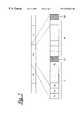
- FIG. 7shows the structure of frames in the TDD system of FIG. 6 .
- DMTdigital multi-tone communications
- Each such symbolfor example symbol 11 is encoded as a set of symbol portions 11 a-c which are transmitted in parallel utilising a plurality of carrier frequencies.
- a plurality of carrier frequenciesIn the example shown three frequencies, f 1 -f 3 , are employed, but in practice more or fewer may be employed.
- Each symbol portionis transmitted on a distinct frequency.
- the boundaries between successive portions of successive symbols 10 - 12 on each of the carrier frequenciesdo not typically arrive simultaneously at a receiver, even though they are typically transmitted simultaneously. It is therefore necessary to perform a symbol alignment process for each underlying carrier frequency separately in order to establish where the corresponding symbol boundaries occur in each received carrier frequency signal. Determining the symbol alignments enables subsequent demodulation and recombination of corresponding symbol portions to recover the original transmitted symbol.
- Symbol alignmentis performed during an initial training phase during which the DMT transmitter and receiver co-operate in a predetermined fashion to provide essential information regarding the communication channel and modem function.
- this training phaseone or more training signals are transmitted to the receiver.
- the present inventionemploys a set of transmitted “active” carrier frequencies which are not continuous across symbol boundaries in the time domain.
- Symbol portions on such an active carriercomprise a prefix portion 14 a-c and a body portion 15 a-c .
- Each prefix portion 14 a-cis a duplicate of a tail portion 16 a-c of body portion 15 a-c respectively, and is arranged such that each prefix portion joins to its associated body portion 15 without any discontinuity in the signal at that point.
- Each active carrier frequencyis chosen such that the symbol length is not an integral multiple of periods of the chosen frequency, consequently a discontinuity does occur between a given body portion 15 a-c of a symbol 11 and the prefix portion 17 a-c of the corresponding symbol portion of the following symbol transmitted on the same frequency.
- the symbol body portioncomprises an encoding of several hundreds of octets of data, and the head portion comprises around 12.5% of the symbol body length.
- FIG. 2illustrates how the series of symbols 10 - 12 of FIG. 1, each transmitted using a number of frequencies, f 1 , f 2 , f 3 , might be received at a DMT receiver.
- the figureshows how portions 11 a-c of symbol 11 have been delayed by differing amounts during transmission, resulting in their arrival at the receiver at different moments as portions 21 a-c respectively.
- Specific symbol alignment at a receivermay be achieved by successively applying each of a set of sampling windows to a received signal, deriving a measure from each such sample, and choosing a suitable window from the set according to chosen criteria applied to those measures.
- FIG. 3In a simplified example illustrated in FIG. 3, five such sampling windows, 34 a - 34 e are shown. In practice more windows could be used for finer alignment. Of the windows shown, 34 a and 34 e fall partially outside the boundaries of the central symbol portion 41 a whilst each of 34 b - 34 d represent samples fully within the symbol.
- sampling windowis one symbol body portion in length and offset in time with respect to each other.
- sampling windowssuch as the extended window described in GB 2,304,504 A may also be used.
- FIG. 3shows the five sampling windows all aligned relative to the same symbol, in practice each such sampling window would be used to sample a number of successive symbols before switching to the next sampling window.
- the methodmay be refined by using coarse window steps initially to obtain an approximate alignment and then applying finer window steps around that alignment to gain fine adjustment.
- different receiver window alignmentsmay be chosen for different carriers.
- FIG. 4there is shown a plot 41 of the sampling window metric against window position, with respect to the mid-point of a symbol.
- the graphillustrates how, as the window moves away from the central position 40 , the metric changes only gradually over a relatively wide range, before dropping off as the sampling window overlaps adjacent symbols and hence is affected by the signal discontinuity across the symbol boundaries.
- the present methodmakes use of other adjacent silent carriers which are explicitly turned off (i.e. have zero transmit power level).
- FIG. 4also shows a plot 46 of a corresponding power metric of such an adjacent silent carrier frequency as the window moves across the same symbol.
- power on the adjacent silent carrierdrops to zero (subject to any noise on that channel) when the sampling window lies fully within the symbol.
- the power level on the adjacent channelrises steeply: importantly it changes more rapidly at this point than does the corresponding power level 41 on the active carrier.
- a metric usedis the difference between the power output on the active channel and a multiple of the power on one or more adjacent silent carriers. In a most preferred embodiment, the difference between the power on an active carrier and approximately fifty times the power on an adjacent silent carrier is used.
- FIGS. 5 ( a-d )there are shown graphical representations of power levels on a set of carrier frequencies at various stages of DMT system operation.
- FIG. 5 ( a )shows an example of carrier power as transmitted during normal operation of the system after symbol alignment: a similar power level is applied to each carrier f 1 -f 6 .
- FIG. 5 ( b )shows an example of the corresponding power levels as they might be applied during symbol alignment according to the present invention.
- Frequencies f 2 and f 5are operated at normal power, whilst adjacent carriers f 0 , f 3 and f 4 , f 6 respectively are silent (i.e. their power output is set to zero).
- silent channel power levelsare set to zero, it is sufficient that they be set to a power level sufficiently low as to permit detection of spectral leakage from adjacent carriers at the receiver.
- the silent carrier power levelshould be in the order of 30 dB lower than that in adjacent active carriers.
- FIG. 5 ( c )shows example carrier frequency power levels at a receiver corresponding to the transmission levels of FIG. 5 ( b ) while the sampling receiver window alignment is suboptimal. Whilst the active frequency carrier received signal strength remains higher than that on the adjacent silent carriers, there is some spectral leakage from the active carriers to those adjacent silent carriers. Where the resulting power increase on the silent carriers exceeds the expected background noise level 50 received on the silent carriers, this gives an indication of window misalignment.
- FIG. 5 ( d )shows example carrier frequency power levels at a receiver corresponding to the transmission levels of FIG. 5 ( b ) while the sampling receiver window alignment is optimal.
- the active frequency carrier received signal strengthis high relative to that on the adjacent silent carriers, and spectral leakage, if any, to adjacent silent carriers is indistinguishable from the expected background noise on those carriers. Such an arrangement is indicative of good sampling receiver window alignment.
- a frequency band of 0-10 MHzmay be partitioned to support 512 carriers. It is not essential that all carriers be utilised for DMT traffic: for example in a preferred scenario, some carrier channels may be reserved for carrying Integrated Services Digital Network (ISDN) or Plain Old Telephone Service (POTS) traffic in parallel with DMT traffic on some or all of the remaining carriers.
- ISDNIntegrated Services Digital Network
- POTSPlain Old Telephone Service
- a plurality of carriersis tuned simultaneously, though the method may be applied to single active carriers. Where a plurality of carriers is tuned simultaneously, then it is preferable to select carriers distributed across the frequency range so as both to determine a suitable compromise symbol alignment and to reduce the susceptibility to locally poor spectral Signal to Noise Ratio (SNR).
- SNRSignal to Noise Ratio
- the transmittercontinually sends the alignment carriers (which may also be modulated to eliminate constant intermodulation products).
- the power level on a chosen active alignment carrieris measured, and at the same time the power level is measured on an adjacent silent carrier. Averaging over a period of time (a given number of symbols) can be used to improve the reliability of this measurement.
- the receiver window alignmentis then shifted and the measurements repeated. This is performed until the complete range over which alignment is expected has been covered.
- the methodcan be extended to find the central point over this range. This can be done by searching the range for the largest metric, then searching both backwards and forwards from that point to find points at which the first metric first falls below a given fraction (for example 0.9) of the maximum. An alignment chosen mid-way between these two points is then used for data transmission. This method of choice serves to avoid the situation where a local maximum of the metric, arising perhaps from a peak in background noise, would otherwise give rise to a sub-optimal choice of receiver window alignment.
- This techniqueis appropriate, inter alia, for use in VDSL DMT modems.
- FIG. 6shows an example of a time division duplex (TDD) network capable of utilising the present invention.
- the networkcomprises a transmission medium 60 , a head-end modem 61 , and subscriber modem 62 - 64 .
- Each modemcomprises a receiver 66 and transmitter 67 coupled both to the medium and to a local subscriber terminal 68 , the receiver comprising at least an input port and a processor.
- Each framecomprises a transmit region T, a first guard region G 1 , a receive region R, and a second guard region G 2 .
- the transmit region of each framecomprises a series of symbols each of one of two types: type A and type B.
- each transmit regionin a preferred embodiment, only one symbol is of type A whilst all others are of type B.
- the first symbol of each frameis of type A whilst subsequent symbols B 1 -B n are each of type B.
- Type A symbolscontain the active and silent carriers for symbol alignment and frequency lock (clock recovery) whilst type B symbols contain only clock recovery active carriers.
- the transmit regions as transmittedare treated as the receive regions at the receiver.
- the receiverreads the Type A symbol inserted by the transmitter as the first symbol in the receive field.
Landscapes
- Engineering & Computer Science (AREA)
- Computer Networks & Wireless Communication (AREA)
- Signal Processing (AREA)
- Mobile Radio Communication Systems (AREA)
Abstract
Description
Claims (23)
Priority Applications (1)
| Application Number | Priority Date | Filing Date | Title |
|---|---|---|---|
| US09/219,005US6353636B1 (en) | 1998-12-23 | 1998-12-23 | Symbol alignment method |
Applications Claiming Priority (1)
| Application Number | Priority Date | Filing Date | Title |
|---|---|---|---|
| US09/219,005US6353636B1 (en) | 1998-12-23 | 1998-12-23 | Symbol alignment method |
Publications (1)
| Publication Number | Publication Date |
|---|---|
| US6353636B1true US6353636B1 (en) | 2002-03-05 |
Family
ID=22817407
Family Applications (1)
| Application Number | Title | Priority Date | Filing Date |
|---|---|---|---|
| US09/219,005Expired - LifetimeUS6353636B1 (en) | 1998-12-23 | 1998-12-23 | Symbol alignment method |
Country Status (1)
| Country | Link |
|---|---|
| US (1) | US6353636B1 (en) |
Cited By (17)
| Publication number | Priority date | Publication date | Assignee | Title |
|---|---|---|---|---|
| US20020034160A1 (en)* | 1996-08-22 | 2002-03-21 | Marchok Daniel J | Apparatus and method for symbol alignment in a multi-point OFDM/DMT digital communications system |
| US6760574B1 (en)* | 2001-04-17 | 2004-07-06 | Centillium Communications, Inc. | Two-dimensional signal detector with dynamic timing phase compensation |
| US20040184484A1 (en)* | 1996-08-22 | 2004-09-23 | Marchok Daniel J. | Apparatus and method for clock synchronization in a multi-point OFDM/DMT digital communications system |
| US20040246890A1 (en)* | 1996-08-22 | 2004-12-09 | Marchok Daniel J. | OFDM/DMT/ digital communications system including partial sequence symbol processing |
| US20060029148A1 (en)* | 2004-08-06 | 2006-02-09 | Tsatsanis Michail K | Method and apparatus for training using variable transmit signal power levels |
| US20060029147A1 (en)* | 2004-08-06 | 2006-02-09 | Tsatsanis Michail K | Method and apparatus for training using variable transmit signal power levels |
| US20060044477A1 (en)* | 2004-08-26 | 2006-03-02 | Stmicroelectronics S.A. | Determination of carrier and symbol frequencies in a signal |
| US7076002B1 (en)* | 2001-04-05 | 2006-07-11 | Ikanos Communication, Inc. | Method and apparatus for symbol boundary synchronization |
| US7277517B1 (en) | 2002-11-15 | 2007-10-02 | 3Com Corporation | Method for achieving symbol alignment to a pre-existing ADSL data exchange |
| US20080298483A1 (en)* | 1996-08-22 | 2008-12-04 | Tellabs Operations, Inc. | Apparatus and method for symbol alignment in a multi-point OFDM/DMT digital communications system |
| US20090003421A1 (en)* | 1998-05-29 | 2009-01-01 | Tellabs Operations, Inc. | Time-domain equalization for discrete multi-tone systems |
| US7616711B2 (en)* | 2004-07-20 | 2009-11-10 | Qualcomm Incorporated | Frequency domain filtering to improve channel estimation in multicarrier systems |
| US20110206108A1 (en)* | 2002-06-07 | 2011-08-25 | Michail Tsatsanis | Method and system for providing a time equalizer for multiline transmission in communication systems |
| US8032095B1 (en)* | 2005-03-03 | 2011-10-04 | Marvell International Ltd. | Method and apparatus for detecting carrier leakage in a wireless or similar system |
| US20130099584A1 (en)* | 2011-10-21 | 2013-04-25 | Qualcomm Incorporated | Wireless power carrier-synchronous communication |
| US9014250B2 (en) | 1998-04-03 | 2015-04-21 | Tellabs Operations, Inc. | Filter for impulse response shortening with additional spectral constraints for multicarrier transmission |
| US20160119047A1 (en)* | 2014-10-28 | 2016-04-28 | Newracom, Inc. | LTF design for WLAN system |
Citations (7)
| Publication number | Priority date | Publication date | Assignee | Title |
|---|---|---|---|---|
| US5187711A (en)* | 1988-09-20 | 1993-02-16 | Fujitsu Limited | Error correction method for multicarrier radio transmission system |
| US5357502A (en)* | 1990-02-06 | 1994-10-18 | France Telecom And Telediffusion De France Sa | Device for the reception of digital data time frequency interlacing, notably for radio broadcasting at high bit rate towards mobile receivers with nyquist temporal window |
| GB2304504A (en) | 1995-08-19 | 1997-03-19 | Northern Telecom Ltd | OFDM receiver includes digital filter |
| US5995568A (en)* | 1996-10-28 | 1999-11-30 | Motorola, Inc. | Method and apparatus for performing frame synchronization in an asymmetrical digital subscriber line (ADSL) system |
| US6074086A (en)* | 1999-04-26 | 2000-06-13 | Intellon Corporation | Synchronization of OFDM signals with improved windowing |
| US6097763A (en)* | 1997-10-31 | 2000-08-01 | Pairgain Technologies, Inc. | MMSE equalizers for DMT systems with cross talk |
| US6134283A (en)* | 1997-11-18 | 2000-10-17 | Amati Communications Corporation | Method and system for synchronizing time-division-duplexed transceivers |
- 1998
- 1998-12-23USUS09/219,005patent/US6353636B1/ennot_activeExpired - Lifetime
Patent Citations (7)
| Publication number | Priority date | Publication date | Assignee | Title |
|---|---|---|---|---|
| US5187711A (en)* | 1988-09-20 | 1993-02-16 | Fujitsu Limited | Error correction method for multicarrier radio transmission system |
| US5357502A (en)* | 1990-02-06 | 1994-10-18 | France Telecom And Telediffusion De France Sa | Device for the reception of digital data time frequency interlacing, notably for radio broadcasting at high bit rate towards mobile receivers with nyquist temporal window |
| GB2304504A (en) | 1995-08-19 | 1997-03-19 | Northern Telecom Ltd | OFDM receiver includes digital filter |
| US5995568A (en)* | 1996-10-28 | 1999-11-30 | Motorola, Inc. | Method and apparatus for performing frame synchronization in an asymmetrical digital subscriber line (ADSL) system |
| US6097763A (en)* | 1997-10-31 | 2000-08-01 | Pairgain Technologies, Inc. | MMSE equalizers for DMT systems with cross talk |
| US6134283A (en)* | 1997-11-18 | 2000-10-17 | Amati Communications Corporation | Method and system for synchronizing time-division-duplexed transceivers |
| US6074086A (en)* | 1999-04-26 | 2000-06-13 | Intellon Corporation | Synchronization of OFDM signals with improved windowing |
Cited By (39)
| Publication number | Priority date | Publication date | Assignee | Title |
|---|---|---|---|---|
| US8243583B2 (en) | 1996-08-22 | 2012-08-14 | Tellabs Operations, Inc. | OFDM/DMT/digital communications system including partial sequence symbol processing |
| US20080298483A1 (en)* | 1996-08-22 | 2008-12-04 | Tellabs Operations, Inc. | Apparatus and method for symbol alignment in a multi-point OFDM/DMT digital communications system |
| US20040184484A1 (en)* | 1996-08-22 | 2004-09-23 | Marchok Daniel J. | Apparatus and method for clock synchronization in a multi-point OFDM/DMT digital communications system |
| US20040246890A1 (en)* | 1996-08-22 | 2004-12-09 | Marchok Daniel J. | OFDM/DMT/ digital communications system including partial sequence symbol processing |
| US6950388B2 (en)* | 1996-08-22 | 2005-09-27 | Tellabs Operations, Inc. | Apparatus and method for symbol alignment in a multi-point OFDM/DMT digital communications system |
| US8665859B2 (en) | 1996-08-22 | 2014-03-04 | Tellabs Operations, Inc. | Apparatus and method for clock synchronization in a multi-point OFDM/DMT digital communications system |
| US8547823B2 (en) | 1996-08-22 | 2013-10-01 | Tellabs Operations, Inc. | OFDM/DMT/ digital communications system including partial sequence symbol processing |
| US20060034166A1 (en)* | 1996-08-22 | 2006-02-16 | Marchok Daniel J | Apparatus and method for symbol alignment in a multi-point OFDM/DMT digital communications system |
| US20020034160A1 (en)* | 1996-08-22 | 2002-03-21 | Marchok Daniel J | Apparatus and method for symbol alignment in a multi-point OFDM/DMT digital communications system |
| US7616553B2 (en) | 1996-08-22 | 2009-11-10 | Tellabs Operations, Inc. | Apparatus and method for clock synchronization in a multi-point OFDM/DMT digital communications system |
| US20080144487A1 (en)* | 1996-08-22 | 2008-06-19 | Tellabs Operations, Inc. | OFDM/DMT/digital communications system including partial sequence symbol processing |
| US20080144731A1 (en)* | 1996-08-22 | 2008-06-19 | Tellabs Operations, Inc. | Apparatus and method for clock synchronization in a multi-point OFDM/DMT digital communications system |
| US7898935B2 (en) | 1996-08-22 | 2011-03-01 | Tellabs Operations, Inc. | OFDM/DMT/digital communications system including partial sequence symbol processing |
| US20110116571A1 (en)* | 1996-08-22 | 2011-05-19 | Tellabs Operations, Inc. | Ofdm/dmt/digital communications system including partial sequence symbol processing |
| US8139471B2 (en) | 1996-08-22 | 2012-03-20 | Tellabs Operations, Inc. | Apparatus and method for clock synchronization in a multi-point OFDM/DMT digital communications system |
| US7613102B2 (en) | 1996-08-22 | 2009-11-03 | Tellabs Operations, Inc. | Apparatus and method for clock synchronization in a multi-point OFDM/DMT digital communications system |
| US9014250B2 (en) | 1998-04-03 | 2015-04-21 | Tellabs Operations, Inc. | Filter for impulse response shortening with additional spectral constraints for multicarrier transmission |
| US20090003421A1 (en)* | 1998-05-29 | 2009-01-01 | Tellabs Operations, Inc. | Time-domain equalization for discrete multi-tone systems |
| US8315299B2 (en) | 1998-05-29 | 2012-11-20 | Tellabs Operations, Inc. | Time-domain equalization for discrete multi-tone systems |
| US7916801B2 (en) | 1998-05-29 | 2011-03-29 | Tellabs Operations, Inc. | Time-domain equalization for discrete multi-tone systems |
| US7076002B1 (en)* | 2001-04-05 | 2006-07-11 | Ikanos Communication, Inc. | Method and apparatus for symbol boundary synchronization |
| US6760574B1 (en)* | 2001-04-17 | 2004-07-06 | Centillium Communications, Inc. | Two-dimensional signal detector with dynamic timing phase compensation |
| US20110206108A1 (en)* | 2002-06-07 | 2011-08-25 | Michail Tsatsanis | Method and system for providing a time equalizer for multiline transmission in communication systems |
| US8139658B2 (en)* | 2002-06-07 | 2012-03-20 | Tokyo Electron Limited | Method and system for providing a time equalizer for multiline transmission in communication systems |
| US7277517B1 (en) | 2002-11-15 | 2007-10-02 | 3Com Corporation | Method for achieving symbol alignment to a pre-existing ADSL data exchange |
| RU2373659C2 (en)* | 2004-07-20 | 2009-11-20 | Квэлкомм Инкорпорейтед | Filtration in frequency domain for improvement of evaluation of channel in systems with several bearing |
| US7616711B2 (en)* | 2004-07-20 | 2009-11-10 | Qualcomm Incorporated | Frequency domain filtering to improve channel estimation in multicarrier systems |
| US20060029148A1 (en)* | 2004-08-06 | 2006-02-09 | Tsatsanis Michail K | Method and apparatus for training using variable transmit signal power levels |
| US7471732B2 (en)* | 2004-08-06 | 2008-12-30 | Aktino, Inc. | Method and apparatus for training using variable transmit signal power levels |
| US20060029147A1 (en)* | 2004-08-06 | 2006-02-09 | Tsatsanis Michail K | Method and apparatus for training using variable transmit signal power levels |
| US7865144B2 (en)* | 2004-08-26 | 2011-01-04 | Stmicroelectronics S.A. | Determination of carrier and symbol frequencies in a signal |
| US20060044477A1 (en)* | 2004-08-26 | 2006-03-02 | Stmicroelectronics S.A. | Determination of carrier and symbol frequencies in a signal |
| US8032095B1 (en)* | 2005-03-03 | 2011-10-04 | Marvell International Ltd. | Method and apparatus for detecting carrier leakage in a wireless or similar system |
| US8737939B1 (en) | 2005-03-03 | 2014-05-27 | Marvell International Ltd. | Method and apparatus for detecting presence of an unmodulated RF carrier prior to a communication frame |
| CN103891156A (en)* | 2011-10-21 | 2014-06-25 | 高通股份有限公司 | Wireless power carrier-synchronous communication |
| US20130099584A1 (en)* | 2011-10-21 | 2013-04-25 | Qualcomm Incorporated | Wireless power carrier-synchronous communication |
| US9264108B2 (en)* | 2011-10-21 | 2016-02-16 | Qualcomm Incorporated | Wireless power carrier-synchronous communication |
| US20160119047A1 (en)* | 2014-10-28 | 2016-04-28 | Newracom, Inc. | LTF design for WLAN system |
| US9893784B2 (en)* | 2014-10-28 | 2018-02-13 | Newracom, Inc. | LTF design for WLAN system |
Similar Documents
| Publication | Publication Date | Title |
|---|---|---|
| US6353636B1 (en) | Symbol alignment method | |
| US4688210A (en) | Method of and arrangement for synchronizing the receiver arrangements in a digital multiplex transmission system | |
| US7295518B1 (en) | Broadband network for coaxial cable using multi-carrier modulation | |
| US6941151B2 (en) | Transmitting apparatus, receiving apparatus, and communication system for formatting data | |
| US9912505B2 (en) | Pilot design for wireless system | |
| US5903608A (en) | Adaptive bit swapping method and device for discrete multitone system | |
| US7580400B2 (en) | Apparatus and method for generating preamble signal for cell identification in an orthogonal frequency division multiplexing system | |
| US6724849B1 (en) | Method and apparatus for timing recovery in ADSL transceivers under a TCM-ISDN crosstalk environment | |
| JPH09505185A (en) | High-speed digital subscriber line discrete multi-tone transmission | |
| US20080187077A1 (en) | Method for estimating crosstalk interferences in a communication network | |
| US7292606B2 (en) | Two-stage symbol alignment method for ADSL transmission in the presence of TCM-ISDN interferers | |
| JP3187024B2 (en) | Communication device and interference removal method in the communication device | |
| JP4582609B2 (en) | Synchronization method | |
| US8705676B2 (en) | Method and apparatus for clock recovery in XDSL transceivers | |
| KR100534410B1 (en) | Sending method, sending apparatus and, receiving method, receiving apparatus of tdma/ofdm system | |
| US6577650B1 (en) | Method of setting-up and controlling synchronization within a modem | |
| US7362798B1 (en) | Method for transmitting data to be transmitted using a subscriber modem | |
| KR100591644B1 (en) | Method and system for synchronizing time-division-duplexed transceivers | |
| US7411998B1 (en) | Method and apparatus for using low power training | |
| EP1071269A1 (en) | Transmission method for subscriber line | |
| JP2001298499A (en) | Digital subscriber line transmission method, transmission apparatus and transmission / reception apparatus under periodic noise environment | |
| Harada et al. | Performance Analysis of an OFDM based wireless ATM communication system | |
| US7190731B2 (en) | System and method for applying transmit windowing in ADSL+networks | |
| WO2006092861A1 (en) | Line terminating apparatus and transmission control method | |
| KR20070059399A (en) | How to measure frequency error |
Legal Events
| Date | Code | Title | Description |
|---|---|---|---|
| AS | Assignment | Owner name:NORTHERN TELECOM LIMITED, CANADA Free format text:ASSIGNMENT OF ASSIGNORS INTEREST;ASSIGNORS:TATE, CHRISTOPHER NEVILLE;WALLACE, ANDREW DAVID;HUMPHREY, LESLIE DEREK;REEL/FRAME:009684/0241;SIGNING DATES FROM 19981214 TO 19981215 | |
| AS | Assignment | Owner name:NORTEL NETWORKS CORPORATION, CANADA Free format text:CHANGE OF NAME;ASSIGNOR:NORTHERN TELECOM LIMITED;REEL/FRAME:010567/0001 Effective date:19990429 | |
| AS | Assignment | Owner name:NORTEL NETWORKS LIMITED, CANADA Free format text:CHANGE OF NAME;ASSIGNOR:NORTEL NETWORKS CORPORATION;REEL/FRAME:011195/0706 Effective date:20000830 Owner name:NORTEL NETWORKS LIMITED,CANADA Free format text:CHANGE OF NAME;ASSIGNOR:NORTEL NETWORKS CORPORATION;REEL/FRAME:011195/0706 Effective date:20000830 | |
| STCF | Information on status: patent grant | Free format text:PATENTED CASE | |
| FPAY | Fee payment | Year of fee payment:4 | |
| FPAY | Fee payment | Year of fee payment:8 | |
| AS | Assignment | Owner name:ROCKSTAR BIDCO, LP, NEW YORK Free format text:ASSIGNMENT OF ASSIGNORS INTEREST;ASSIGNOR:NORTEL NETWORKS LIMITED;REEL/FRAME:027164/0356 Effective date:20110729 | |
| FPAY | Fee payment | Year of fee payment:12 | |
| AS | Assignment | Owner name:ROCKSTAR CONSORTIUM US LP, TEXAS Free format text:ASSIGNMENT OF ASSIGNORS INTEREST;ASSIGNOR:ROCKSTAR BIDCO, LP;REEL/FRAME:032399/0442 Effective date:20120509 | |
| AS | Assignment | Owner name:RPX CLEARINGHOUSE LLC, CALIFORNIA Free format text:ASSIGNMENT OF ASSIGNORS INTEREST;ASSIGNORS:ROCKSTAR CONSORTIUM US LP;ROCKSTAR CONSORTIUM LLC;BOCKSTAR TECHNOLOGIES LLC;AND OTHERS;REEL/FRAME:034924/0779 Effective date:20150128 | |
| AS | Assignment | Owner name:JPMORGAN CHASE BANK, N.A., AS COLLATERAL AGENT, IL Free format text:SECURITY AGREEMENT;ASSIGNORS:RPX CORPORATION;RPX CLEARINGHOUSE LLC;REEL/FRAME:038041/0001 Effective date:20160226 | |
| AS | Assignment | Owner name:RPX CORPORATION, CALIFORNIA Free format text:RELEASE (REEL 038041 / FRAME 0001);ASSIGNOR:JPMORGAN CHASE BANK, N.A.;REEL/FRAME:044970/0030 Effective date:20171222 Owner name:RPX CLEARINGHOUSE LLC, CALIFORNIA Free format text:RELEASE (REEL 038041 / FRAME 0001);ASSIGNOR:JPMORGAN CHASE BANK, N.A.;REEL/FRAME:044970/0030 Effective date:20171222 | |
| AS | Assignment | Owner name:JEFFERIES FINANCE LLC, NEW YORK Free format text:SECURITY INTEREST;ASSIGNOR:RPX CLEARINGHOUSE LLC;REEL/FRAME:046485/0644 Effective date:20180619 | |
| AS | Assignment | Owner name:RPX CLEARINGHOUSE LLC, CALIFORNIA Free format text:RELEASE BY SECURED PARTY;ASSIGNOR:JEFFERIES FINANCE LLC;REEL/FRAME:054305/0505 Effective date:20201023 |