US6353561B1 - Semiconductor integrated circuit and method for controlling the same - Google Patents
Semiconductor integrated circuit and method for controlling the sameDownload PDFInfo
- Publication number
- US6353561B1 US6353561B1US09/397,845US39784599AUS6353561B1US 6353561 B1US6353561 B1US 6353561B1US 39784599 AUS39784599 AUS 39784599AUS 6353561 B1US6353561 B1US 6353561B1
- Authority
- US
- United States
- Prior art keywords
- signal
- circuit
- decoding
- command
- mask
- Prior art date
- Legal status (The legal status is an assumption and is not a legal conclusion. Google has not performed a legal analysis and makes no representation as to the accuracy of the status listed.)
- Expired - Lifetime
Links
Images


Classifications
- G—PHYSICS
- G11—INFORMATION STORAGE
- G11C—STATIC STORES
- G11C7/00—Arrangements for writing information into, or reading information out from, a digital store
- G—PHYSICS
- G11—INFORMATION STORAGE
- G11C—STATIC STORES
- G11C7/00—Arrangements for writing information into, or reading information out from, a digital store
- G11C7/10—Input/output [I/O] data interface arrangements, e.g. I/O data control circuits, I/O data buffers
- G11C7/1078—Data input circuits, e.g. write amplifiers, data input buffers, data input registers, data input level conversion circuits
- G11C7/109—Control signal input circuits
- G—PHYSICS
- G11—INFORMATION STORAGE
- G11C—STATIC STORES
- G11C11/00—Digital stores characterised by the use of particular electric or magnetic storage elements; Storage elements therefor
- G11C11/21—Digital stores characterised by the use of particular electric or magnetic storage elements; Storage elements therefor using electric elements
- G11C11/34—Digital stores characterised by the use of particular electric or magnetic storage elements; Storage elements therefor using electric elements using semiconductor devices
- G11C11/40—Digital stores characterised by the use of particular electric or magnetic storage elements; Storage elements therefor using electric elements using semiconductor devices using transistors
- G11C11/401—Digital stores characterised by the use of particular electric or magnetic storage elements; Storage elements therefor using electric elements using semiconductor devices using transistors forming cells needing refreshing or charge regeneration, i.e. dynamic cells
- G11C11/4063—Auxiliary circuits, e.g. for addressing, decoding, driving, writing, sensing or timing
- G11C11/407—Auxiliary circuits, e.g. for addressing, decoding, driving, writing, sensing or timing for memory cells of the field-effect type
- G11C11/409—Read-write [R-W] circuits
- G11C11/4093—Input/output [I/O] data interface arrangements, e.g. data buffers
- G—PHYSICS
- G11—INFORMATION STORAGE
- G11C—STATIC STORES
- G11C7/00—Arrangements for writing information into, or reading information out from, a digital store
- G11C7/10—Input/output [I/O] data interface arrangements, e.g. I/O data control circuits, I/O data buffers
- G11C7/1006—Data managing, e.g. manipulating data before writing or reading out, data bus switches or control circuits therefor
- G—PHYSICS
- G11—INFORMATION STORAGE
- G11C—STATIC STORES
- G11C7/00—Arrangements for writing information into, or reading information out from, a digital store
- G11C7/10—Input/output [I/O] data interface arrangements, e.g. I/O data control circuits, I/O data buffers
- G11C7/1072—Input/output [I/O] data interface arrangements, e.g. I/O data control circuits, I/O data buffers for memories with random access ports synchronised on clock signal pulse trains, e.g. synchronous memories, self timed memories
- G—PHYSICS
- G11—INFORMATION STORAGE
- G11C—STATIC STORES
- G11C7/00—Arrangements for writing information into, or reading information out from, a digital store
- G11C7/10—Input/output [I/O] data interface arrangements, e.g. I/O data control circuits, I/O data buffers
- G11C7/1078—Data input circuits, e.g. write amplifiers, data input buffers, data input registers, data input level conversion circuits
Definitions
- the present inventionrelates to semiconductor integrated circuits and a method for controlling semiconductor integrated circuits.
- the frequency of a controller (CPU) that controls a dynamic random access memory (DRAM)is high and has been increasing.
- external commandsare generated at high speed cycles by the controller and the DRAM is required to process such high speed external commands.
- a synchronous DRAMhas thus been proposed to receive the high speed external command synchronously with either a first internal clock signal or a second internal clock signal. More specifically, the DRAM divides the high frequency external clock signal from the controller in half. The phases of the divided signal are offset from each other by 180°. As a result, a first internal clock signal and a second internal clock signal having phases offset from each other by 180° are generated. The DRAM receives the external command in synchronism with an external clock signal when either the first internal clock signal or the second internal clock signal rises.
- the DRAMincludes a first signal processing circuit for processing an external command received synchronously with the first internal clock signal and a second signal processing circuit for processing an external command received synchronously with the second internal clock signal.
- the first and second signal processing circuitsprocess external commands separately so that the high speed external commands can be followed.
- (1) Invalidation of the external commands from the DRAM controllermay be delayed in accordance with the wire length and wire capacitance.
- the first and second signal processing circuitsmust receive an external command that is the same as the previous command and process the command once more. This hinders accurate decoding of the external command.
- Fluctuations in the temperature or power supply voltagemay vary the frequency of the first and second internal clock signals.
- the first and second signal processing circuitsmay receive an external command that is the same as the previous external command.
- the present inventionprovides a method for controlling a semiconductor integrated circuit device having a plurality of signal processing circuits, which process an input signal.
- the methodincludes the steps of receiving the input signal in one of the plurality of signal processing circuits and outputting an internal signal in response to a clock signal, and prohibiting another of the signal processing circuits from processing the input signal for a predetermined time in response to the internal signal.
- a semiconductor integrated circuit devicein a further aspect of the present invention, includes a plurality of signal processing circuits for processing an input signal.
- a prohibiting circuitis connected to the plurality of signal processing circuits. The prohibiting circuit prohibits another of the signal processing circuits from processing the input signals for a predetermined time in response to an internal signal which is output from one of the signal processing circuit based on the input signal.
- a semiconductor memory devicein another aspect of the present invention, includes a plurality of input buffers for receiving an external command in synchronism with a plurality of internal clock signals.
- a command decoderis connected to the plurality of input buffers to receive the external commands from the input buffers, decoding the external command, and generating internal commands.
- the command decoderhas a plurality of decoding circuits. Each of the decoding circuits decodes the external commands in accordance with an associated one of the plurality of internal clock signals.
- a mask circuitis connected to the plurality of decoding circuits. The mask circuit prevents another of the decoding circuits from decoding the external command for a predetermined time when one of the decoding circuits decodes the external command.
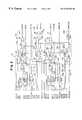
- FIG. 1is a block diagram showing a data input circuit of a synchronous DRAM according to a first embodiment of the present invention
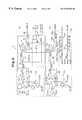
- FIG. 2is a circuit diagram showing a command decoder of the data input circuit of FIG. 1;
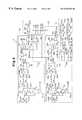
- FIG. 3is a circuit diagram showing a mask circuit of the data input circuit of FIG. 1;
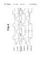
- FIG. 4is a timing chart showing the operation of the data input circuit of FIG. 1;
- FIG. 5is a circuit diagram showing a mask circuit according to a second embodiment of the present invention.
- FIG. 6is a timing chart showing the operation of a data input circuit according to a second embodiment of the present invention.
- a synchronous DRAM data input circuit 10according to a first embodiment of the present invention will now be described with reference to FIGS. 1 to 4 .
- the data input circuit 10includes a first decoding circuit 12 a and a second decoding circuit 12 b (FIG. 2) which receive external commands in synchronism with a first internal clock signal CLK 0 Z and a second internal clock signal CLK 18 Z, respectively.
- a first decoding circuit 12 a and a second decoding circuit 12 bFIG. 2 which receive external commands in synchronism with a first internal clock signal CLK 0 Z and a second internal clock signal CLK 18 Z, respectively.
- the other decoding circuit 12 a , 12 bis prohibited from processing an external command for a predetermined period.
- the synchronous DRAM data input circuit 10acquires external commands together with addresses.
- the data input circuit 10includes a plurality of input buffers 11 , a command decoder 12 for decoding the external commands acquired by each of the input buffers 11 and generating internal commands, an RAS circuit 13 for performing various processes such as reading and writing based on the internal command, a mask circuit (prohibiting circuit) 14 for controlling the command decoder 12 , and a delay locked loop (DLL) circuit 16 .
- DLLdelay locked loop
- the DLL circuit 16receives an external clock signal CLK from a DRAM controller and divides the clock signal CLK in half to generates the first and second internal clock signals CLK 0 Z, CLK 18 Z.
- the DLL circuit 16provides the first and second internal clock signals CLK 0 Z, CLK 18 Z to the input buffers 11 .
- the frequency of the first and second internal clock signals CLK 0 Z, CLK 18 Zis half of that of the external clock CLK. Thus, if the frequency of the external clock CLK is, for example, 400 MHz, the frequency of the first and second internal clock signals CLK 0 Z, CLK 18 Z is 200 MHz.
- the first and second internal clock signals CLK 0 Z, CLK 18 Zhave phases of 0° and 180°, respectively, offset from each other by half a cycle.
- Each of the input buffers 11receives external command signals PDZ, PDX, SFFCLR, OEZ, OEX, WEZ, WEX through input pads 15 . These external command signals form the external command.
- the input buffers 11receive the external command signals PDZ, PDX, SFFCLR, OEZ, OEX, WEZ, WEX in synchronism with the rising of the first and second internal clock signals CLK 0 Z, CLK 18 Z sent from the DLL circuit 16 .
- the input buffers 11When receiving the external command signals PDZ, PDX, SFFCLR, OEZ, OEX, WEZ, WEX in response to the rising of the first and second internal clock signals CLK 0 Z, CLK 18 Z, the input buffers 11 are permitted to acquire the external commands and addresses provided in synchronism with the 400 MHz external clock signal CLK.
- the external command signalsinclude power-down signals PDZ, PDX, a chip enable signal SFFCLR, output enable signals OEZ, OEX, and write enable signals WEZ, WEX.
- the power-down signals PDZ, PDXare complementary signals. When the DRAM is actuated, the power-down signal PDZ is high, while the power-down signal PDX is low.
- the output signals OEZ, OEX and the write enable signals WEZ, WEXare also complementary signals.
- the chip enable signal SFFCLRis a pulse signal that is synchronized with the first and second internal clock signals CLK 0 Z, CLK 18 Z when the DRAM is actuated.
- the command signals acquired in response to the first internal clock signal CLK 0 Zare denoted as PDZ 0 , PDX 0 , SFFCLR 0 , OEZ 0 , OEX 0 , WEZ 0 , WEX 0 .
- the command signals acquired in response to the second internal clock signal CLK 18 Zare denoted as PDZ 18 , PDX 18 , SFFCLR 18 , OEZ 18 , OEX 18 , WEZ 18 , WEX 18 .
- the command decoder 12decodes the external commands from the input buffers 11 and generates internal commands.
- the command decoder 12will now be described with reference to FIG. 2 .
- the command decoder 12includes the first and second decoding circuits (signal processing circuit) 12 a , 12 b.
- the first decoding circuit 12 areceives and decodes the power-down signals PDZ 0 , PDX 0 , the chip enable signal SFFCLR 0 , the output enable signals OEZ 0 , OEX 0 , and the write enable signals WEZ 0 , WEX 0 that are acquired in response to the rising of the first internal clock signal CLK 0 Z and generates the internal commands.
- the second decoding circuit 12 breceives and decodes the power-down signals PDZ 18 , PDX 18 , the chip enable signal SFFCLR 18 , the output enable signals OEZ 18 , OEX 18 , and the write enable signals WEZ 18 , WEX 18 that are acquired in response to the rising of the second internal clock signal CLK 18 Z and generates the internal commands.
- the first decoding circuit 12 aincludes a flash write (FWRT) command decoding portion 21 , a read command decoding portion 22 , a write command decoding portion 23 , a mode register set decoding portion 24 , a mask command generating portion 25 , and an output control portion 26 .
- FWRTflash write
- the FWRT command decoding portion 21includes a NAND circuit 31 , two NOR circuits 32 , 33 , and an inverter 34 .
- the NAND circuit 31has three input terminals which receive the output enable signal OEX 0 , the write enable signal WEX 0 , and the chip enable signal SFFCLR 0 .
- the NAND circuit 31provides a low signal SG 1 to the NOR circuit 32 when the output enable signal OEX 0 , the write enable signal WEX 0 , and the chip enable signal SFFCLR 0 are all high.
- the NOR circuit 32has two input terminals which receive the signal SG 1 from the NAND circuit 31 and a control signal SX 1 from the output control portion 26 . When the signals SX 1 , SG 1 are both low, the NOR circuit 32 provides the NOR circuit 33 with a high signal SG 2 . The NOR circuit 33 outputs a high internal flash write command signal FWRTPZ via the inverter 34 .
- a flash write operationis executed when the internal flash write command signal FWRTPZ is high and prohibited when the flash write command signal FWRTPZ is low. If the control signal SX 1 from the output control portion 26 is low when the output enable signal OEX 0 , the write enable signal WEX 0 , and the chip enable signal SFFCLR 0 are all high, the internal flash write command signal FWRTPZ is caused to be high. In this state, the DRAM is set in a flash write mode.
- the NOR circuit 33receives a signal SG 2 b from a NOR circuit 32 b of a flash write (FWRT) command decoding portion 21 b employed in the second decoding circuit 12 b .
- a high signal SG 2 bcauses the internal flash write command signal FWRTPZ to be high and sets the DRAM in the flash write mode.
- the read command decoding portion 22includes a NAND circuit 35 , a NOR circuit 36 , and two inverters 37 , 38 .
- the NAND circuit 35has three input terminals which receive the output enable signal OEZ 0 , the write enable signal WEX 0 , and the chip enable signal SFFCLR 0 . Further, the NAND circuit 35 provides a low signal SG 3 to the NOR circuit 36 when the output enable signal OEZ 0 , the write enable signal WEX 0 , and the chip enable signal SFFCLR 0 are all high.
- the NOR circuit 36has two input terminals which receive the signal SG 3 from the NAND circuit 35 and a control signal SX 2 from the output control portion 26 . When the signals SX 2 and SG 3 are both low, the NOR circuit 36 outputs a high internal read command signal RDPZ 0 via the inverters 37 , 38 .
- a read operationis executed when the internal read command signal RDPZ 0 is high and prohibited when the internal read command signal RDPZ 0 is low. If the control signal SX 2 from the output control portion 26 is low when the output enable signal OEZ 0 , the write enable signal WEX 0 , and the chip enable signal SFFCLR 0 are all high, the internal read command signal RDPZ 0 is caused to be high. In this state, the DRAM is set in a read mode.
- the write command decoding portion 23includes a NAND circuit 39 , a NOR circuit 40 , and two inverters 41 , 42 .
- the NAND circuit 39has three input terminals which receive the output enable signal OEX 0 , the write enable signal WEZ 0 , and the chip enable signal SFFCLR 0 . Further, the NAND circuit 39 provides a low signal SG 4 to the NOR circuit 40 when the output enable signal OEX 0 , the write enable signal WEZ 0 , and the chip enable signal SFFCLR 0 are all high.
- the NOR circuit 40has two input terminals which receive the signal SG 4 from the NAND circuit 39 and the control signal SX 2 from the output control portion 26 . When the signals SX 2 , SG 4 are both low, the NOR circuit 40 outputs a high internal write command signal WRTPZ 0 via the inverters 41 , 42 .
- a write operationis executed when the internal write command signal WRTPZ 0 is high and prohibited when the internal write command signal WRTPZ 0 is low. If the control signal SX 2 from the output control portion 26 is low when the output enable signal OEX 0 , the write enable signal WEZ 0 , and the chip enable signal SFFCLR 0 are all high, the internal write command signal WRTPZ 0 is caused to be high. In this state, the DRAM is set in a write mode.
- the mode register set decoding portion 24includes a NAND circuit 43 , two NOR circuits 44 , 45 , and an inverter 46 .
- the NAND circuit 43has three input terminals which receive the output enable signal OEZ 0 , the write enable signal WEZ 0 , and the chip enable signal SFFCLR 0 .
- the NAND circuit 43provides a low signal SG 5 to the NOR circuit 44 when the output enable signal OEZ 0 , the write enable signal WEZ 0 , and the chip enable signal SFFCLR 0 are all high.
- the NOR circuit 44has two input terminals which receive the signal SG 5 from the NAND circuit 43 and the control signal SX 1 from the output control portion 26 . When the signals SX 1 and SG 5 are both low, the NOR circuit 44 provides the NOR circuit 45 with a high signal SG 6 . As a result, the NOR circuit 45 outputs a high internal mode command signal MRSPZ via the inverter 46 .
- a mode setting operationis executed when the internal mode command signal MRSPZ is high and prohibited when the internal mode command signal MRSPZ is low. If the control signal SX 1 from the output control portion 26 is low when the output enable signal OEZ 0 , the write enable signal WEZ 0 , and the chip enable signal SFFCLR 0 are all high, the internal mode command signal MRSPZ is caused to be high. In this state, the DRAM is set in a mode setting operation mode.
- the NOR circuit 45receives a signal SG 6 b from a NOR circuit 44 b of a mode register set decoding portion 24 b employed in the second decoding circuit 12 b .
- a high signal SG 6 bcauses the internal mode command signal MRSPZ to be high and sets the DRAM in the mode setting operation mode.
- the mask command generating portion 25includes a NOR circuit 47 and three inverters 48 , 49 , 50 .
- the NOR circuit 47has two input terminals which receive the control signal SX 1 from the output control portion 26 and the chip enable signal SFFCLR 0 via the inverter 48 . Further, the NOR circuit 47 provides a high mask command signal COMMPZ 0 via the inverters 49 , 50 if the control signal SX 1 is low when the chip enable signal SFFCLR 0 is high.
- a high mask command signal COMMPZ 0prohibits operation of the second decoding circuit 12 b for a predetermined period. If the control signal SX 1 from the output control portion 26 is low when the chip enable signal SFFCLR 0 is high, the mask command signal COMMPZ 0 is high.
- the output control portion 26includes two NAND circuits 51 , 52 which receive the power-down signal PDZ 0 and a first mask signal ACENZ 0 .
- the first mask signal ACENZ 0is provided from the mask circuit 14 (FIG. 1 ).
- the first mask signal ACENZ 0remains low for a predetermined period after the second decoding circuit 12 b provides the RAS circuit 13 with an internal command. If the power-down signal PDZ 0 is high when the first mask signal ACENZ 0 is low, the output control portion 26 outputs high control signals SX 1 , SX 2 .
- high control signals SX 1 , SX 2prohibit decoding by the FWRT command decoding portion 21 of the first decoding circuit 12 a , the read command decoding portion 22 , the write command decoding portion 23 , the mode register decoding portion 24 , and the mask command generating portion 25 from decoding the power-down signals PDZ 0 , PDX 0 , the chip enable signal SFFCLR 0 , the output enable signals OEZ 0 , OEX 0 , and the write enable signals WEZ 0 , WEX 0 .
- the control signals SX 1 , SX 2are low if the RAS circuit 13 is not provided with an internal command from the second decoding circuit 12 b while the first mask signal ACENZ 0 is high.
- low control signals SX 1 , SX 2cause the FWRT command decoding portion 21 of the first decoding circuit 12 a , the read command decoding portion 22 , the write command decoding portion 23 , the mode register decoding portion 24 , and the mask command generating portion 25 to decode the power-down signals PDZ 0 , PDX 0 , the chip enable signal SFFCLR 0 , the output enable signals OEZ 0 , OEX 0 , and the write enable signals WEZ 0 , WEX 0 .
- the internal commands generated through the decoding processthat is, the internal flash write command signal FWRTPZ, the internal read command signal RDPZ 0 , the internal write command signal WRTPZ 0 , and the internal mode command signal MRSPZ, are provided to the RAS circuit 13 .
- the second decoding circuit 12 b of the command decoder 12will now be described.
- the second decoding circuit 12 bdecodes the external commands (the power-down signals PDZ 18 , PDX 18 , the chip enable signal SFFCLR 18 , the output enable signals OEZ 18 , OEX 18 , and the write enable signals WEZ 18 , WEX 18 ) that are acquired in synchronism with the second internal clock signal CLK 18 Z and generates the internal commands.
- the external commandsthe power-down signals PDZ 18 , PDX 18 , the chip enable signal SFFCLR 18 , the output enable signals OEZ 18 , OEX 18 , and the write enable signals WEZ 18 , WEX 18
- the second decoding circuit 12 bincludes a FWRT command decoding portion 21 b , a read command decoding portion 22 b , a write command decoding portion 23 b , a mode register set decoding portion 24 b , a mask command generating portion 25 b , and an output control portion 26 b.
- the circuit portions 21 b - 26 bcorrespond to the circuit portions 21 - 26 of the first decoding circuit 12 a , respectively.
- Devices that are the same or similar to corresponding devices in the circuit portions 21 - 26 of the first decoding circuit 12 aare denoted with the same reference numeral followed by the letter “b”. These devices will not be described.
- the circuit portions 21 b - 26 bdiffer from the circuit portions 21 - 26 in that the FWRT command decoding portion 21 b and the mode register set decoding portion 24 b include part of the FWRT command decoding portion 21 and the mode register set decoding portion 24 b , respectively, and in that the output control portion 26 b receives a second mask signal ACENZ 18 .
- the second decoding circuit 12 bWhen the second mask signal ACENZ 18 is low, the second decoding circuit 12 b provides the internal flash write command signal FWRTPZ, an internal read command signal RDPZ 18 , an internal write command signal WRTPZ 18 , and the internal mode command signal MRSPZ to the RAS circuit 13 and a second mask command signal COMMPZ 18 to the mask circuit 14 in accordance with the power-down signals PDZ 18 , PDX 18 , the chip enable signal SFFCLR 18 , the output enable signals OEZ 18 , OEX 18 , and the write enable signals WEZ 18 , WEX 18 .
- the circuit portions 21 b 25 b of the second decoding circuit 12 bis prohibited from providing the internal flash write command signal FWRTPZ, the internal read command signal RDPZ 18 , the internal write command signal WRTPZ 18 , and from providing the second mask command signal COMMPZ 18 to the mask circuit 14 .
- the output of the NOR circuits 47 , 47 b of the respective mask command generating portions 25 , 25 bare provided to the NOR circuit 53 .
- the NOR circuit 53provides a command signal COMMPZ to the RAS circuit 13 via an inverter 54 .
- the RAS circuit 13receives the decoded internal commands FWRTPZ, RDPZ 0 , WRTPZ 0 , MRSPZ, COMMPZ, RDPZ 18 , WRTPZ 18 from the first and second decoding circuits 12 a , 12 b .
- the RAS circuit 13performs various operations, such as a write process and a read process, based on these internal commands.
- the mask circuit 14which generates the first and second mask signals ACENZ 0 , ACENZ 18 in accordance with the first and second mask command signals COMMPZ 0 , COMMPZ 18 , will now be described with reference to FIG. 3 .
- the mask circuit 14includes a clock generating circuit 61 , a mode set circuit 62 , a first mask signal generating circuit 63 , and a second mask signal generating circuit 64 .
- the clock generating circuit 61includes a first generating portion 61 a and a second generating portion 61 b .
- the first generating portion 61 areceives the first internal clock signal CLK 0 Z and outputs complementary first gate clock signals CLKAZ, CLKAX.
- the first clock generating portion 61 aincludes six inverters 71 a - 76 a , which are connected to one another in series.
- the inverter 71 areceives the first internal clock signal CLK 0 Z and the inverter 76 a outputs a delayed first internal clock signal CLK 0 Z as the first gate clock signal CLKAZ.
- the inverter 75 aoutputs the first gate clock signal CLKAX.
- the delay time of the first gate clock signals CLKAZ, CLKAX relative to the first internal clock signal CLK 0 Zcorresponds to the time from when the command decoder 12 acquires the external command to when the decoded external command is output as an internal command.
- the second generating portion 61 breceives the second internal clock signal CLK 18 Z and outputs complementary second gate clock signals CLKBZ, CLKBX.
- the second clock generating portion 61 bincludes six inverters 71 b - 76 b , which are connected to one another in series.
- the inverter 71 breceives the second internal clock signal CLK 18 Z and the inverter 76 b outputs the delayed second internal clock signal CLK 18 Z as the second gate clock signal CLKBZ.
- the inverter 75 boutputs the second gate clock signal CLKBX.
- the delay time of the second gate clock signals CLKBZ, CLKBX relative to the second internal clock signal CLK 18 Zcorresponds to the time from when the command decoder 12 acquires the external command to when the decoded external command is output as an internal command.
- the mode set circuit 62includes two NOR circuits 77 , 78 and an inverter 79 .
- the NOR circuit 77includes two input terminals which receive a first mode signal DL 3 Z and a second mode signal DL 6 Z.
- the NOR circuit 78includes two input terminals which receive a third mode signal DL 1 OZ and a fourth mode signal DL 12 Z.
- the first to fourth mode signals DL 3 Z, DL 6 Z, DL 10 Z, DL 12 Zindicate the frequency of the external clock signal CLK used by the DRAM and are generated by the DRAM based on the frequency of the first and second internal clock signals CLK 0 Z, CLK 18 Z generated by the DLL circuit 16 .
- the first mode signal DL 3 Zis high when the frequency of the external clock signal CLK is 100 MHz.
- the second mode signal DL 6 Zis high when the frequency of the external clock signal CLK is 200 MHz.
- the third mode signal DL 10 Zis high when the frequency of the external clock signal CLK is 333 MHz.
- the fourth mode signal DL 12 Zis high when the frequency of the external clock signal CLK is 400 MHz.
- the first to fourth mode signals DL 3 Z, DL 6 Z, DL 10 Z, DL 12 Zare low when the external clock signal CLK has a frequency that differs from the corresponding value.
- the NOR circuit 77outputs a high first speed mode signal MS 1 via the inverter 79 . That is., the mode set circuit 62 outputs a high first speed mode signal MS 1 if the DRAM is used when the frequency of the external clock signal CLK is low, such as 100 MHz or 200 MHz.
- the NOR circuit 78outputs a low second speed mode signal MS 2 . That is, the mode set circuit 62 outputs a low second speed mode signal MS 2 if the DRAM is used when the frequency of the external clock signal CLK is high at 300 MHz or 400 MHz.
- the first mask signal generating circuit 63includes a flip-flop (FF) circuit 80 , NOR circuits 83 , 85 , inverters 84 , 86 , and a return circuit 90 .
- the FF circuit 80includes a set NOR circuit 81 and a reset circuit 82 .
- the set NOR circuit 81receives the first mask command signal COMMPZ 0 from the mask command generating portion 25 of the first decoding circuit 12 a .
- the reset NOR circuit 82has three input terminals which receive a starter signal STTZ, a reset signal SG 10 from the NOR circuit 83 , and a signal SG 11 from the NOR circuit 81 .
- the starter signal STTZremains high for a certain period when the DRAM is actuated.
- the NOR circuit 83has two input terminals which receive the second speed mode signal MS 2 from the mode set circuit 62 and a return signal SG 20 via the inverter 84 . If the second speed mode signal MS 2 is low when the return signal SG 20 is high, the NOR circuit 83 provides a high reset signal SG 10 to the NOR circuit 82 .
- the NOR circuit 81 of the FF circuit 80provides a high signal SG 11 to the NOR circuit 85 when the DRAM is actuated.
- the NOR circuit 81receives a high first mask command signal COMMPZ 0
- the FF circuit 80inverts the signal and provides a low signal SG 11 to the NOR circuit 85 .
- the NOR circuit 85has two input terminals which receive the signal SG 11 from the FF circuit 80 and the first speed mode signal MS 1 from the mode set circuit 62 . If the first speed mode signal MS 1 is low when the signal SG 11 is high, the NOR circuit 85 provides a low signal SG 12 to the inverter 86 . Further, if the first speed mode signal MS 1 and the signal SG 11 are both low, the NOR circuit 85 provides a high signal SG 12 to the inverter 86 .
- the inverter 86receives the signal SG 12 from the NOR circuit 85 and provides the second decoding circuit 12 b of the output control portion 26 b with the second mask signal ACENZ 18 , which is equal to the signal SG 12 inverted.
- the second mask signal ACENZ 18is high. In this state, if the first mask command signal COMMPZ 0 rises and the signal SG 11 falls, the second mask signal ACENZ 18 falls. From this state, if the FF circuit 80 outputs a high signal SG 11 in response to a high reset signal SG 10 , the second mask signal ACENZ 18 rises.
- the return circuit 90includes two transfer gate circuits 91 , 92 , transistors T 1 -T 3 , an inverter 94 , and NAND circuits 93 , 95 .
- the return circuit 90measures the elapsed time from when the second mask signal ACENZ 18 falls. After a predetermined elapsed time, the return circuit 90 causes the mask signal ACENZ 18 to rise.
- the transfer gate circuits 91 , 92are each formed by a PMOS transistor and an NMOS transistor.
- the PMOS transistor gateis provided with the first gate clock signal CLKAZ and the NMOS transistor gate is provided with the first gate clock signal CLKAX.
- the transfer gate circuit 92the PMOS transistor gate is provided with the first gate clock signal CLKAX and the NMOS transistor gate is provided with the first gate clock signal CLKAZ. Therefore, the transfer gate circuit 91 , 92 is activated and deactivated alternately in accordance with the first gate clock signals CLKAZ, CLKAX. More specifically, the transfer gate circuit 91 is activated when the first gate clock signal CLKAZ (first internal clock signal CLK 0 Z) rises and deactivated when the first gate clock signal CLKAZ falls.
- the transfer gate circuit 91has an input terminal connected to the output terminal of the NOR circuit 85 and an output terminal connected to the NAND circuit 93 . Further, the transfer gate circuit 91 provides the signal SG 12 from the NOR circuit 85 to the NAND circuit 93 .
- the NAND circuit 93receives the signal SG 12 via the transfer gate circuit 91 and also directly from the NOR circuit 85 . Further, the NAND circuit 93 has an output terminal connected to the input terminal of the CMOS transistor T 1 and the output terminal of the gate circuit 91 .
- the PMOS transistor T 2is connected between the CMOS transistor T 1 and a high potential power supply Vii and activated and deactivated by the first gate clock signal CLKAX.
- the NMOS transistor T 3is connected between the CMOS transistor T 1 and a ground potential Vss and activated and deactivated by the first gate clock signal CLKAZ.
- the CMOS transistor T 1is activated when the transfer gate circuit 91 is deactivated, and deactivated when the transfer gate circuit 91 is activated.
- the NAND circuit 93 and the CMOS transistor T 1form a latch circuit.
- the NAND circuit 93receives a low signal SG 12 from the NOR circuit 85 and provides a high signal to the transfer gate circuit 92 when receiving a low signal SG 12 from the NOR circuit 85 . If the CMOS transistor T 1 is, activated when the transfer gate circuit 91 is deactivated, the CMOS transistor T 1 receives a high signal from the NAND circuit 93 and provides a low signal to the NAND circuit 93 . This causes the output signal of the NAND circuit 93 to go high.
- the output signal of the NAND circuit 93falls. Since the transfer gate circuit 92 is deactivated, the low signal from the NAND circuit 93 is not immediately provided to the inverter 94 via the transfer gate circuit 92 .
- the NAND circuit 93provides the low signal to the inverter circuit 94 via the transfer gate circuit 92 when the first gate clock signals CLKAZ, CLKAX are inverted (i.e., when the first internal clock signal CLK 0 Z rises) and the transfer gate circuit 92 is activated.
- the NAND circuit 95has two input terminals which receive the signal from the inverter circuit 94 and the signal SG 12 from the NOR circuit 85 . Further, the NAND circuit 95 has an output terminal connected to the input terminal of the inverter 94 .
- the inverter 94 and the NAND circuit 95form a latch circuit.
- the transfer gate circuit 92is deactivated when the signal SG 12 and the signal from the inverter 94 are both low.
- the output signal of the inverter 94remains low when the signal SG 12 rises since the transfer gate circuit 92 is deactivated.
- the inverter 94provides a high signal to the NAND circuit 95 .
- the NAND circuit 95provides a low signal to the inverter 94 in response to receiving a low signal from the inverter 94 . This causes the output signal of the inverter 94 to go high.
- the output signal of the inverter 94is provided to the NOR circuit 83 via the inverter 84 as the return signal SG 20 . If the return signal SG 20 falls when the second speed mode signal MS 2 is low, the NOR circuit 83 provides a high reset signal SG 10 to the NOR circuit 82 .
- the return signal SG 12 from the NOR circuit 85falls, the return signal SG 20 falls after the first internal clock signal CLK 0 Z that acquires the external command rises.
- the second mask signal ACENZ 18rises one cycle of the first internal clock signal CLK 0 Z subsequent to the acquisition of the external command.
- the second decoding circuit 12 bis prohibited from decoding the external commands acquired in synchronism with the second internal clock signal CLK 18 Z until the second mask signal ACENZ 18 rises.
- the second mask signal generating circuit 64has substantially the same circuit structure as the first mask signal generating circuit 63 . However, the second mask signal generating circuit 64 differs from the first mask signal generating circuit 63 in that the generating circuit 64 receives the second mask command signal COMMPZ 18 and the second gate clock signals CLKBZ, CLKBX and in that the first mask signal ACENZ 0 is provided to the output control portion 26 of the first decoding circuit 12 a .
- Devices that are the same or similar to corresponding devices in the first mask signal generating circuit 63are denoted with the same reference numeral followed by the letter “a”. The second mask signal generating circuit 64 will not be described since it operates in substantially the same manner as the first mask signal generating circuit 63 .
- the second mask signal generating circuit 64if a return signal SG 12 a from a NOR circuit 85 a falls, a return signal SG 20 a falls when the second internal clock signal CLK 18 Z that acquires the external command rises. In other words, the first mask signal ACENZ 0 rises one cycle of the second internal clock signal CLK 18 Z subsequent to the acquisition of the external command.
- the first decoding circuit 12 ais prevented from decoding the external commands acquired in synchronism with the first internal clock signal CLK 0 Z until the first mask signal ACENZ 0 rises.
- a high first mask command signal COMMPZ 0is provided to the first mask signal generating circuit 63 of the mask circuit 14 .
- the first mask signal generating circuit 63provides a low second mask signal ACENZ 18 to the output control portion 26 b of the second decoding circuit 12 b in response to the high first mask command signal COMMPZ 0 .
- the output control portion 26 bthen provides high control signals SX 1 b , SX 2 b to the FWRT command decoding portion 21 b , the mode register set decoding portion 24 b , and the mask command generating portion 25 b in response to the low second mask signal ACENZ 18 . This prevents decoding of external command signals by the circuit portions 21 b - 25 b of the second decoding circuit 12 b.
- the first mask signal generating circuit 63outputs a high second mask signal ACENZ 18 after the first internal clock signal CLK 0 Z that acquires the external command rises.
- the second internal clock signal CLK 18 Zrises substantially simultaneously with the falling of the first internal clock signal CLK 0 Z that acquires the external command.
- the circuit portions 21 b - 25 b of the second decoding circuit 12 bare prevented from decoding external command signals while the second internal clock signal CLK 18 Z is high.
- the circuit portions 21 b - 25 bdo not decode external command signals when the external command signals are provided to the command decoder 12 in a relatively slow cycle even if the input buffer 11 provides external command signals that are the same as the previous cycle in response to the rising of the second internal clock signal CLK 18 Z. This prevents the command decoder 12 from decoding the same external command signal continuously and repeatedly providing the resulting internal commands to the RAS circuit 13 . Thus, the external command is decoded accurately.
- the input of an external command that is the same as the prior external commandis prevented even if the wire length or wire capacitance of the DRAM causes a delay in the invalidation of the external command from the DRAM controller.
- the return circuits 90 , 90 adetermine the period during which the first and second mask signals ACENZ 0 , ACENZ 18 remain low in accordance with the first and second internal clock signals CLK 0 Z, CLK 18 Z (more precisely, the first and second gate clock signals CLKAZ, CLKAX, CLKBZ, CLKBX generated in accordance with the first and second internal clock signals CLK 0 Z, CLK 18 Z).
- the prohibition timeis repeatedly determined based on such changes. Accordingly, the DRAM automatically adjusts the prohibition time when the frequency of the external clock signal CLK is varied.
- the mode set circuit 62provides a high first speed mode signal MS 1 to the first and second mask signal generating circuits 63 , 64 when the frequency of the external clock signal CLK is low at 100 MHz or 200 MHz. Further, the mode set circuit 62 provides a high second speed mode signal MS 2 to the first and second mask signal generating circuits 63 , 64 when the frequency of the external clock signal CLK is high at 333 MHz or 400 MHz.
- the first and second speed mode signals MS 1 , MS 2are both high. This keeps the first and second mask signals ACENZ 0 , ACENZ 18 high even if the first and second mask signal generating circuits 63 , 64 provide high first and second mask command signals COMMPZ 0 , COMMPZ 18 .
- the first and second speed mode signals MS 1 , MS 2are both low. This causes the first and second mask signal generating circuits 63 , 64 to generate low first and second mask signals ACENZ 0 , ACENZ 18 in response to high first and second mask command signals COMMPZ 0 , COMMPZ 18 . Accordingly, the operation of the mask circuit 14 is stopped when the cycle of the external command signals is capable of following the first and second internal clock signals CLK 0 Z, CLK 18 Z.
- a data input circuit according to a second embodiment of the present inventionwill now be described with reference to FIG. 5 .
- the second embodimentdiffers from the first embodiment in that it employs a different mask circuit 114 . Otherwise, like or same reference numerals are given to those components that are the same as the corresponding components of the first embodiment and will not be described.
- the mask circuit 114includes a clock generating circuit 161 having capacitors Ca, Cb, resistors Ra, Rb, NAND circuits 97 a , 97 b , and inverters 98 a , 98 b , 99 a , 99 b in lieu of the inverters 76 a , 76 b employed in the first embodiment.
- the period during which the first gate clock signal CLKAZ remains lowis determined by a delay circuit that includes the capacitor Ca and the resistor Ra.
- the period during which the second gate clock signal CLKBZ remains lowis determined by a delay circuit that includes the capacitor Cb and the resistor Rb.
- a first mask signal generating circuit 163includes a NAND circuit 100 which receives the first and second mask signals ACENZ 0 , ACENZ 18 from the first and second mask signal generating circuits 63 , 64 .
- the NAND circuit 100provides the mask signal ACENZ via the inverter 101 to the output control portions 26 a , 26 b of the first and second decoding circuits 12 a , 12 b in the command decoder 12 .
- the first and second decoding circuits 12 a , 12 bare both prevented from decoding external commands into internal commands.
- a return circuit 90includes an inverter 102 , a latch circuit formed by inverters 103 , 104 , and a third transfer gate circuit 105 which are arranged between the transfer gate circuit 92 and the inverter 94 .
- a return circuit 90 aincludes an inverter 102 a , a latch circuit formed by inverters 103 a , 104 a , and a third transfer gate circuit 105 a which are arranged between the transfer gate circuit 92 a and the inverter 94 a.
- the inverter 102 of the first mask signal generating circuit 163receives a signal from the NAND circuit 93 via the transfer gate circuit 92 .
- the signal of the inverter 102is provided to the latch circuit formed by the inverters 103 , 104 .
- the latch circuitprovides a signal to the inverter 94 via the third transfer gate circuit 105 .
- the second gate clock signal CLKBXis provided to the PMOS transistor gate of the third transfer gate circuit 105
- the second gate clock signal CLKBZis provided to the NMOS transistor gate of the third transfer gate circuit 105 .
- Activation of the third transfer gate circuit 105also activates the transfer gate circuit 91 .
- deactivation of the third transfer gate circuit 105deactivates the transfer gate circuit 91 .
- the inverter 102 a of the first mask signal generating circuit 164receives a signal from the NAND circuit 93 a via the transfer gate circuit 92 a .
- the signal of the inverter 102 ais provided to the latch circuit formed by the inverters 103 a , 104 a .
- the latch circuitprovides a signal to the inverter 94 a via the third transfer gate circuit 105 a.
- the first gate clock signal CLKAXis provided to the PMOS transistor gate of the third transfer gate circuit 105 a
- the first gate clock signal CLKAZis provided to the NMOS transistor gate of the first transfer gate circuit 105 a .
- Activation of the third transfer gate circuit 105 aalso activates the transfer gate circuit 91 a .
- deactivation of the third transfer gate circuit 105 adeactivates the transfer gate circuit 91 a.
- the signal SG 12If the signal SG 12 is low, the signal from the NAND circuit 93 and the inverter 103 is high, and the signal from the inverter 94 is low, rising of the signal SG 12 keeps the signal from the NAND circuit 93 high since the transfer gate circuit 91 is deactivated. Accordingly, the signal output by the inverter 103 remains high even when the transfer gate circuit 92 is activated. Furthermore, the signal output by the inverter 94 remains low since the third transfer gate circuit 105 is deactivated.
- the transfer gate circuit 91When the transfer gate circuit 91 is activated, the signal from the NAND circuit 93 falls. Since the transfer gate circuit 92 is deactivated in this state, the signal from the inverter 103 remains high. Accordingly, the signal output by the inverter 94 remains low even when the third transfer gate circuit 105 is activated.
- the transfer gate circuit 91When the transfer gate circuit 91 is deactivated (i.e., when the transfer gate circuit 92 is activated), the signal from the inverter 103 falls. Since the third transfer gate circuit 105 is deactivated in this state, the signal from the inverter 94 remains low.
- the transfer gate circuit 91 and the third transfer gate circuit 105are activated (i.e., if the transfer gate circuit 92 is activated), the signal output by the inverter 94 remains high in accordance with the low signal from the inverter 103 .
- the signal from the inverter 94is provided as the return signal SG 20 to the NOR circuit 83 via the inverter 84 .
- the NOR circuit 83provides a high reset signal SG 10 to the NOR circuit 82 .
- the return signal SG 20falls after the pulse following the pulse of the first internal clock signal CLK 0 Z that acquires the external command rises.
- the second mask signal ACENZ 18rises after two cycles of the first internal clock signal CLK 0 Z, after the external command is acquired.
- the first and second internal clock signals CLK 0 Z, CLK 18 Zdo not decode the external command acquired by the first and second internal clock signals CLK 0 Z, CLK 18 Z as long as the second mask signal ACENZ 18 remains high.
- the return circuit 90 aWhen the signal SG 12 a from the second mask signal generating circuit 164 rises, the return circuit 90 a operates in the same manner as the return circuit 90 of the first mask signal generating circuit 163 . Thus, the operation of the return circuit 90 a will not be described.
- the first and second mask signals ACENZ 0 , ACENZ 18 of the first and second mask signal generating circuits 163 , 164are integrated into the single mask signal ACENZ.
- the mask signal ACENZis provided to the first and second decoding circuits 12 a , 12 b . If either the first decoding circuit 12 a or the second decoding circuit 12 b generates a high first or second command signal CMMPZ 0 , CMMPZ 18 , the first mask signal generating circuit 163 outputs a high mask signal ACENZ. This prevents the first and second decoding circuits 12 a , 12 b from decoding external commands.
- the return circuits 90 , 90 ainvalidate the mask signal ACENZ (the signal ACENZ being high) a cycle and one-half of the first and second internal clock signals CLK 0 Z, CLK 18 Z after the first and second mask command signals CMMPZ 0 , CMMPZ 18 are provided to the associated first and second mask signal generating circuits 163 , 164 .
- the DRAM controllerwhen the DRAM controller requires time for the output of the next command, the DRAM controller need not provide a no-operation command (NOP command) before the output of the next command.
- NOP commandno-operation command
- the mask signals ACENZ 0 , ACENZ 18 , ACENZmay be used to control the input buffers 11 instead of the command decoder 12 . This stops the operation of the command decoder 12 and the input buffers 11 for a predetermined period and reduces power consumption.
- the application of the present inventionis not limited to semiconductor memory devices, such as a DRAM.
- the present inventionmay be applied to a semiconductor that processes commands and data acquired by a plurality of internal clock signals.
- the commands and addressesmay be acquired separately in accordance with the first and second internal command signals CLK 0 Z, CLK 18 Z.
Landscapes
- Engineering & Computer Science (AREA)
- Microelectronics & Electronic Packaging (AREA)
- Computer Hardware Design (AREA)
- Dram (AREA)
Abstract
Description
Claims (10)
Applications Claiming Priority (2)
| Application Number | Priority Date | Filing Date | Title |
|---|---|---|---|
| JP10-265220 | 1998-09-18 | ||
| JP26522098AJP4156721B2 (en) | 1998-09-18 | 1998-09-18 | Semiconductor integrated circuit device |
Publications (1)
| Publication Number | Publication Date |
|---|---|
| US6353561B1true US6353561B1 (en) | 2002-03-05 |
Family
ID=17414201
Family Applications (1)
| Application Number | Title | Priority Date | Filing Date |
|---|---|---|---|
| US09/397,845Expired - LifetimeUS6353561B1 (en) | 1998-09-18 | 1999-09-17 | Semiconductor integrated circuit and method for controlling the same |
Country Status (3)
| Country | Link |
|---|---|
| US (1) | US6353561B1 (en) |
| JP (1) | JP4156721B2 (en) |
| KR (1) | KR100622031B1 (en) |
Cited By (41)
| Publication number | Priority date | Publication date | Assignee | Title |
|---|---|---|---|---|
| US6545940B2 (en)* | 2000-09-25 | 2003-04-08 | Fujitsu Limited | Semiconductor integrated circuit having enhanced acquisition of external signal |
| US20070014168A1 (en)* | 2005-06-24 | 2007-01-18 | Rajan Suresh N | Method and circuit for configuring memory core integrated circuit dies with memory interface integrated circuit dies |
| US20070058410A1 (en)* | 2005-09-02 | 2007-03-15 | Rajan Suresh N | Methods and apparatus of stacking DRAMs |
| US20080028135A1 (en)* | 2006-07-31 | 2008-01-31 | Metaram, Inc. | Multiple-component memory interface system and method |
| US20080025137A1 (en)* | 2005-06-24 | 2008-01-31 | Metaram, Inc. | System and method for simulating an aspect of a memory circuit |
| US20080025125A1 (en)* | 2006-07-31 | 2008-01-31 | Metaram, Inc. | Interface circuit system and method for performing power management operations in conjunction with only a portion of a memory circuit |
| US20080025123A1 (en)* | 2006-07-31 | 2008-01-31 | Metaram, Inc. | Interface circuit system and method for autonomously performing power management operations in conjunction with a plurality of memory circuits |
| US20080025124A1 (en)* | 2006-07-31 | 2008-01-31 | Metaram, Inc. | Interface circuit system and method for performing power management operations utilizing power management signals |
| US20080025108A1 (en)* | 2006-07-31 | 2008-01-31 | Metaram, Inc. | System and method for delaying a signal communicated from a system to at least one of a plurality of memory circuits |
| US20080031030A1 (en)* | 2006-07-31 | 2008-02-07 | Metaram, Inc. | System and method for power management in memory systems |
| US20080031072A1 (en)* | 2006-07-31 | 2008-02-07 | Metaram, Inc. | Power saving system and method for use with a plurality of memory circuits |
| US20080082763A1 (en)* | 2006-10-02 | 2008-04-03 | Metaram, Inc. | Apparatus and method for power management of memory circuits by a system or component thereof |
| US20080103753A1 (en)* | 2006-07-31 | 2008-05-01 | Rajan Suresh N | Memory device with emulated characteristics |
| US20080109595A1 (en)* | 2006-02-09 | 2008-05-08 | Rajan Suresh N | System and method for reducing command scheduling constraints of memory circuits |
| US20100214864A1 (en)* | 2007-09-06 | 2010-08-26 | Micron Technology, Inc. | Memory device command decoding system and memory device and processor-based system using same |
| US8055833B2 (en) | 2006-10-05 | 2011-11-08 | Google Inc. | System and method for increasing capacity, performance, and flexibility of flash storage |
| US8060774B2 (en) | 2005-06-24 | 2011-11-15 | Google Inc. | Memory systems and memory modules |
| US8077535B2 (en) | 2006-07-31 | 2011-12-13 | Google Inc. | Memory refresh apparatus and method |
| US8081474B1 (en) | 2007-12-18 | 2011-12-20 | Google Inc. | Embossed heat spreader |
| US8080874B1 (en) | 2007-09-14 | 2011-12-20 | Google Inc. | Providing additional space between an integrated circuit and a circuit board for positioning a component therebetween |
| US8089795B2 (en) | 2006-02-09 | 2012-01-03 | Google Inc. | Memory module with memory stack and interface with enhanced capabilities |
| US8090897B2 (en) | 2006-07-31 | 2012-01-03 | Google Inc. | System and method for simulating an aspect of a memory circuit |
| US8111566B1 (en) | 2007-11-16 | 2012-02-07 | Google, Inc. | Optimal channel design for memory devices for providing a high-speed memory interface |
| US8130560B1 (en) | 2006-11-13 | 2012-03-06 | Google Inc. | Multi-rank partial width memory modules |
| US8169233B2 (en) | 2009-06-09 | 2012-05-01 | Google Inc. | Programming of DIMM termination resistance values |
| US8209479B2 (en) | 2007-07-18 | 2012-06-26 | Google Inc. | Memory circuit system and method |
| US8244971B2 (en) | 2006-07-31 | 2012-08-14 | Google Inc. | Memory circuit system and method |
| US8280714B2 (en) | 2006-07-31 | 2012-10-02 | Google Inc. | Memory circuit simulation system and method with refresh capabilities |
| US8327104B2 (en) | 2006-07-31 | 2012-12-04 | Google Inc. | Adjusting the timing of signals associated with a memory system |
| US8335894B1 (en) | 2008-07-25 | 2012-12-18 | Google Inc. | Configurable memory system with interface circuit |
| US8386722B1 (en) | 2008-06-23 | 2013-02-26 | Google Inc. | Stacked DIMM memory interface |
| US8397013B1 (en) | 2006-10-05 | 2013-03-12 | Google Inc. | Hybrid memory module |
| US8438328B2 (en) | 2008-02-21 | 2013-05-07 | Google Inc. | Emulation of abstracted DIMMs using abstracted DRAMs |
| JP2013175261A (en)* | 2012-02-24 | 2013-09-05 | Sk Hynix Inc | Command decoders |
| US8566516B2 (en) | 2006-07-31 | 2013-10-22 | Google Inc. | Refresh management of memory modules |
| US8796830B1 (en) | 2006-09-01 | 2014-08-05 | Google Inc. | Stackable low-profile lead frame package |
| US9171585B2 (en) | 2005-06-24 | 2015-10-27 | Google Inc. | Configurable memory circuit system and method |
| US9507739B2 (en) | 2005-06-24 | 2016-11-29 | Google Inc. | Configurable memory circuit system and method |
| US9632929B2 (en) | 2006-02-09 | 2017-04-25 | Google Inc. | Translating an address associated with a command communicated between a system and memory circuits |
| US10013371B2 (en) | 2005-06-24 | 2018-07-03 | Google Llc | Configurable memory circuit system and method |
| US20190027210A1 (en) | 2011-02-23 | 2019-01-24 | Rambus Inc. | Protocol for memory power-mode control |
Families Citing this family (5)
| Publication number | Priority date | Publication date | Assignee | Title |
|---|---|---|---|---|
| JP4864187B2 (en)* | 2000-01-19 | 2012-02-01 | 富士通セミコンダクター株式会社 | Semiconductor integrated circuit |
| JP5226161B2 (en)* | 2001-02-23 | 2013-07-03 | 富士通セミコンダクター株式会社 | Semiconductor memory device and information processing system |
| JP4570321B2 (en)* | 2002-10-29 | 2010-10-27 | ルネサスエレクトロニクス株式会社 | Semiconductor memory device |
| JP2007200504A (en)* | 2006-01-30 | 2007-08-09 | Fujitsu Ltd | Semiconductor memory, memory controller, and semiconductor memory control method |
| JP5669175B2 (en)* | 2010-06-28 | 2015-02-12 | ルネサスエレクトロニクス株式会社 | Electronics |
Citations (5)
| Publication number | Priority date | Publication date | Assignee | Title |
|---|---|---|---|---|
| US5748560A (en)* | 1995-12-25 | 1998-05-05 | Mitsubishi Denki Kabushiki Kaisha | Synchronous semiconductor memory device with auto precharge operation easily controlled |
| US5867447A (en)* | 1995-11-10 | 1999-02-02 | Nec Corporation | Synchronous semiconductor memory having a write execution time dependent upon a cycle time |
| US5973988A (en)* | 1998-07-15 | 1999-10-26 | Mitsubishi Denki Kabushiki Kaisha | Semiconductor memory device having circuit for monitoring set value of mode register |
| US6088290A (en)* | 1997-08-13 | 2000-07-11 | Kabushiki Kaisha Toshiba | Semiconductor memory device having a power-down mode |
| US6144614A (en)* | 1998-07-17 | 2000-11-07 | Fujitsu Limited | Semiconductor integrated circuit having a clock and latch circuits for performing synchronous switching operations |
- 1998
- 1998-09-18JPJP26522098Apatent/JP4156721B2/ennot_activeExpired - Fee Related
- 1999
- 1999-09-17USUS09/397,845patent/US6353561B1/ennot_activeExpired - Lifetime
- 1999-09-17KRKR1019990040079Apatent/KR100622031B1/ennot_activeExpired - Fee Related
Patent Citations (5)
| Publication number | Priority date | Publication date | Assignee | Title |
|---|---|---|---|---|
| US5867447A (en)* | 1995-11-10 | 1999-02-02 | Nec Corporation | Synchronous semiconductor memory having a write execution time dependent upon a cycle time |
| US5748560A (en)* | 1995-12-25 | 1998-05-05 | Mitsubishi Denki Kabushiki Kaisha | Synchronous semiconductor memory device with auto precharge operation easily controlled |
| US6088290A (en)* | 1997-08-13 | 2000-07-11 | Kabushiki Kaisha Toshiba | Semiconductor memory device having a power-down mode |
| US5973988A (en)* | 1998-07-15 | 1999-10-26 | Mitsubishi Denki Kabushiki Kaisha | Semiconductor memory device having circuit for monitoring set value of mode register |
| US6144614A (en)* | 1998-07-17 | 2000-11-07 | Fujitsu Limited | Semiconductor integrated circuit having a clock and latch circuits for performing synchronous switching operations |
Cited By (109)
| Publication number | Priority date | Publication date | Assignee | Title |
|---|---|---|---|---|
| US6545940B2 (en)* | 2000-09-25 | 2003-04-08 | Fujitsu Limited | Semiconductor integrated circuit having enhanced acquisition of external signal |
| US7609567B2 (en) | 2005-06-24 | 2009-10-27 | Metaram, Inc. | System and method for simulating an aspect of a memory circuit |
| US20070050530A1 (en)* | 2005-06-24 | 2007-03-01 | Rajan Suresh N | Integrated memory core and memory interface circuit |
| US7515453B2 (en) | 2005-06-24 | 2009-04-07 | Metaram, Inc. | Integrated memory core and memory interface circuit |
| US10013371B2 (en) | 2005-06-24 | 2018-07-03 | Google Llc | Configurable memory circuit system and method |
| US20080025137A1 (en)* | 2005-06-24 | 2008-01-31 | Metaram, Inc. | System and method for simulating an aspect of a memory circuit |
| US8615679B2 (en) | 2005-06-24 | 2013-12-24 | Google Inc. | Memory modules with reliability and serviceability functions |
| US8060774B2 (en) | 2005-06-24 | 2011-11-15 | Google Inc. | Memory systems and memory modules |
| US20070014168A1 (en)* | 2005-06-24 | 2007-01-18 | Rajan Suresh N | Method and circuit for configuring memory core integrated circuit dies with memory interface integrated circuit dies |
| US8359187B2 (en) | 2005-06-24 | 2013-01-22 | Google Inc. | Simulating a different number of memory circuit devices |
| US9507739B2 (en) | 2005-06-24 | 2016-11-29 | Google Inc. | Configurable memory circuit system and method |
| US9171585B2 (en) | 2005-06-24 | 2015-10-27 | Google Inc. | Configurable memory circuit system and method |
| US8386833B2 (en) | 2005-06-24 | 2013-02-26 | Google Inc. | Memory systems and memory modules |
| US8619452B2 (en) | 2005-09-02 | 2013-12-31 | Google Inc. | Methods and apparatus of stacking DRAMs |
| US20080170425A1 (en)* | 2005-09-02 | 2008-07-17 | Rajan Suresh N | Methods and apparatus of stacking drams |
| US20070058410A1 (en)* | 2005-09-02 | 2007-03-15 | Rajan Suresh N | Methods and apparatus of stacking DRAMs |
| US8582339B2 (en) | 2005-09-02 | 2013-11-12 | Google Inc. | System including memory stacks |
| US7599205B2 (en) | 2005-09-02 | 2009-10-06 | Metaram, Inc. | Methods and apparatus of stacking DRAMs |
| US7379316B2 (en) | 2005-09-02 | 2008-05-27 | Metaram, Inc. | Methods and apparatus of stacking DRAMs |
| US8811065B2 (en) | 2005-09-02 | 2014-08-19 | Google Inc. | Performing error detection on DRAMs |
| US8566556B2 (en) | 2006-02-09 | 2013-10-22 | Google Inc. | Memory module with memory stack and interface with enhanced capabilities |
| US9542352B2 (en) | 2006-02-09 | 2017-01-10 | Google Inc. | System and method for reducing command scheduling constraints of memory circuits |
| US9542353B2 (en) | 2006-02-09 | 2017-01-10 | Google Inc. | System and method for reducing command scheduling constraints of memory circuits |
| US20080109595A1 (en)* | 2006-02-09 | 2008-05-08 | Rajan Suresh N | System and method for reducing command scheduling constraints of memory circuits |
| US8089795B2 (en) | 2006-02-09 | 2012-01-03 | Google Inc. | Memory module with memory stack and interface with enhanced capabilities |
| US9632929B2 (en) | 2006-02-09 | 2017-04-25 | Google Inc. | Translating an address associated with a command communicated between a system and memory circuits |
| US9727458B2 (en) | 2006-02-09 | 2017-08-08 | Google Inc. | Translating an address associated with a command communicated between a system and memory circuits |
| US8797779B2 (en) | 2006-02-09 | 2014-08-05 | Google Inc. | Memory module with memory stack and interface with enhanced capabilites |
| US8327104B2 (en) | 2006-07-31 | 2012-12-04 | Google Inc. | Adjusting the timing of signals associated with a memory system |
| US20080031072A1 (en)* | 2006-07-31 | 2008-02-07 | Metaram, Inc. | Power saving system and method for use with a plurality of memory circuits |
| US7590796B2 (en) | 2006-07-31 | 2009-09-15 | Metaram, Inc. | System and method for power management in memory systems |
| US7580312B2 (en) | 2006-07-31 | 2009-08-25 | Metaram, Inc. | Power saving system and method for use with a plurality of memory circuits |
| US7472220B2 (en) | 2006-07-31 | 2008-12-30 | Metaram, Inc. | Interface circuit system and method for performing power management operations utilizing power management signals |
| US7724589B2 (en) | 2006-07-31 | 2010-05-25 | Google Inc. | System and method for delaying a signal communicated from a system to at least one of a plurality of memory circuits |
| US7730338B2 (en) | 2006-07-31 | 2010-06-01 | Google Inc. | Interface circuit system and method for autonomously performing power management operations in conjunction with a plurality of memory circuits |
| US7761724B2 (en) | 2006-07-31 | 2010-07-20 | Google Inc. | Interface circuit system and method for performing power management operations in conjunction with only a portion of a memory circuit |
| US20080028135A1 (en)* | 2006-07-31 | 2008-01-31 | Metaram, Inc. | Multiple-component memory interface system and method |
| US8019589B2 (en) | 2006-07-31 | 2011-09-13 | Google Inc. | Memory apparatus operable to perform a power-saving operation |
| US8041881B2 (en) | 2006-07-31 | 2011-10-18 | Google Inc. | Memory device with emulated characteristics |
| US20080025125A1 (en)* | 2006-07-31 | 2008-01-31 | Metaram, Inc. | Interface circuit system and method for performing power management operations in conjunction with only a portion of a memory circuit |
| US20080239857A1 (en)* | 2006-07-31 | 2008-10-02 | Suresh Natarajan Rajan | Interface circuit system and method for performing power management operations in conjunction with only a portion of a memory circuit |
| US8077535B2 (en) | 2006-07-31 | 2011-12-13 | Google Inc. | Memory refresh apparatus and method |
| US20080025123A1 (en)* | 2006-07-31 | 2008-01-31 | Metaram, Inc. | Interface circuit system and method for autonomously performing power management operations in conjunction with a plurality of memory circuits |
| US20080025124A1 (en)* | 2006-07-31 | 2008-01-31 | Metaram, Inc. | Interface circuit system and method for performing power management operations utilizing power management signals |
| US20080239858A1 (en)* | 2006-07-31 | 2008-10-02 | Suresh Natarajan Rajan | Interface circuit system and method for autonomously performing power management operations in conjunction with a plurality of memory circuits |
| US8090897B2 (en) | 2006-07-31 | 2012-01-03 | Google Inc. | System and method for simulating an aspect of a memory circuit |
| US20080025108A1 (en)* | 2006-07-31 | 2008-01-31 | Metaram, Inc. | System and method for delaying a signal communicated from a system to at least one of a plurality of memory circuits |
| US8112266B2 (en) | 2006-07-31 | 2012-02-07 | Google Inc. | Apparatus for simulating an aspect of a memory circuit |
| US20080031030A1 (en)* | 2006-07-31 | 2008-02-07 | Metaram, Inc. | System and method for power management in memory systems |
| US8154935B2 (en) | 2006-07-31 | 2012-04-10 | Google Inc. | Delaying a signal communicated from a system to at least one of a plurality of memory circuits |
| US7581127B2 (en) | 2006-07-31 | 2009-08-25 | Metaram, Inc. | Interface circuit system and method for performing power saving operations during a command-related latency |
| US9047976B2 (en) | 2006-07-31 | 2015-06-02 | Google Inc. | Combined signal delay and power saving for use with a plurality of memory circuits |
| US8244971B2 (en) | 2006-07-31 | 2012-08-14 | Google Inc. | Memory circuit system and method |
| US8280714B2 (en) | 2006-07-31 | 2012-10-02 | Google Inc. | Memory circuit simulation system and method with refresh capabilities |
| US7392338B2 (en) | 2006-07-31 | 2008-06-24 | Metaram, Inc. | Interface circuit system and method for autonomously performing power management operations in conjunction with a plurality of memory circuits |
| US8972673B2 (en) | 2006-07-31 | 2015-03-03 | Google Inc. | Power management of memory circuits by virtual memory simulation |
| US8340953B2 (en) | 2006-07-31 | 2012-12-25 | Google, Inc. | Memory circuit simulation with power saving capabilities |
| US7386656B2 (en) | 2006-07-31 | 2008-06-10 | Metaram, Inc. | Interface circuit system and method for performing power management operations in conjunction with only a portion of a memory circuit |
| US8868829B2 (en) | 2006-07-31 | 2014-10-21 | Google Inc. | Memory circuit system and method |
| US20080037353A1 (en)* | 2006-07-31 | 2008-02-14 | Metaram, Inc. | Interface circuit system and method for performing power saving operations during a command-related latency |
| US20080126687A1 (en)* | 2006-07-31 | 2008-05-29 | Suresh Natarajan Rajan | Memory device with emulated characteristics |
| US8745321B2 (en) | 2006-07-31 | 2014-06-03 | Google Inc. | Simulating a memory standard |
| US8671244B2 (en) | 2006-07-31 | 2014-03-11 | Google Inc. | Simulating a memory standard |
| US8631220B2 (en) | 2006-07-31 | 2014-01-14 | Google Inc. | Adjusting the timing of signals associated with a memory system |
| US20080103753A1 (en)* | 2006-07-31 | 2008-05-01 | Rajan Suresh N | Memory device with emulated characteristics |
| US20080126689A1 (en)* | 2006-07-31 | 2008-05-29 | Suresh Natarajan Rajan | Memory device with emulated characteristics |
| US8566516B2 (en) | 2006-07-31 | 2013-10-22 | Google Inc. | Refresh management of memory modules |
| US20080109206A1 (en)* | 2006-07-31 | 2008-05-08 | Rajan Suresh N | Memory device with emulated characteristics |
| US8595419B2 (en) | 2006-07-31 | 2013-11-26 | Google Inc. | Memory apparatus operable to perform a power-saving operation |
| US8601204B2 (en) | 2006-07-31 | 2013-12-03 | Google Inc. | Simulating a refresh operation latency |
| US20080104314A1 (en)* | 2006-07-31 | 2008-05-01 | Rajan Suresh N | Memory device with emulated characteristics |
| US8796830B1 (en) | 2006-09-01 | 2014-08-05 | Google Inc. | Stackable low-profile lead frame package |
| US20080082763A1 (en)* | 2006-10-02 | 2008-04-03 | Metaram, Inc. | Apparatus and method for power management of memory circuits by a system or component thereof |
| US8055833B2 (en) | 2006-10-05 | 2011-11-08 | Google Inc. | System and method for increasing capacity, performance, and flexibility of flash storage |
| US8977806B1 (en) | 2006-10-05 | 2015-03-10 | Google Inc. | Hybrid memory module |
| US8370566B2 (en) | 2006-10-05 | 2013-02-05 | Google Inc. | System and method for increasing capacity, performance, and flexibility of flash storage |
| US8397013B1 (en) | 2006-10-05 | 2013-03-12 | Google Inc. | Hybrid memory module |
| US8751732B2 (en) | 2006-10-05 | 2014-06-10 | Google Inc. | System and method for increasing capacity, performance, and flexibility of flash storage |
| US8446781B1 (en) | 2006-11-13 | 2013-05-21 | Google Inc. | Multi-rank partial width memory modules |
| US8130560B1 (en) | 2006-11-13 | 2012-03-06 | Google Inc. | Multi-rank partial width memory modules |
| US8760936B1 (en) | 2006-11-13 | 2014-06-24 | Google Inc. | Multi-rank partial width memory modules |
| US8209479B2 (en) | 2007-07-18 | 2012-06-26 | Google Inc. | Memory circuit system and method |
| US9281037B2 (en)* | 2007-09-06 | 2016-03-08 | Micron Technology, Inc. | Memory device command decoding system and memory device and processor-based system using same |
| US10127969B2 (en) | 2007-09-06 | 2018-11-13 | Micron Technology, Inc. | Memory device command receiving and decoding methods |
| US20100214864A1 (en)* | 2007-09-06 | 2010-08-26 | Micron Technology, Inc. | Memory device command decoding system and memory device and processor-based system using same |
| US9633713B2 (en) | 2007-09-06 | 2017-04-25 | Micron Technology, Inc. | Memory device command receiving and decoding methods |
| US8080874B1 (en) | 2007-09-14 | 2011-12-20 | Google Inc. | Providing additional space between an integrated circuit and a circuit board for positioning a component therebetween |
| US8675429B1 (en) | 2007-11-16 | 2014-03-18 | Google Inc. | Optimal channel design for memory devices for providing a high-speed memory interface |
| US8111566B1 (en) | 2007-11-16 | 2012-02-07 | Google, Inc. | Optimal channel design for memory devices for providing a high-speed memory interface |
| US8705240B1 (en) | 2007-12-18 | 2014-04-22 | Google Inc. | Embossed heat spreader |
| US8730670B1 (en) | 2007-12-18 | 2014-05-20 | Google Inc. | Embossed heat spreader |
| US8081474B1 (en) | 2007-12-18 | 2011-12-20 | Google Inc. | Embossed heat spreader |
| US8631193B2 (en) | 2008-02-21 | 2014-01-14 | Google Inc. | Emulation of abstracted DIMMS using abstracted DRAMS |
| US8438328B2 (en) | 2008-02-21 | 2013-05-07 | Google Inc. | Emulation of abstracted DIMMs using abstracted DRAMs |
| US8386722B1 (en) | 2008-06-23 | 2013-02-26 | Google Inc. | Stacked DIMM memory interface |
| US8762675B2 (en) | 2008-06-23 | 2014-06-24 | Google Inc. | Memory system for synchronous data transmission |
| US8335894B1 (en) | 2008-07-25 | 2012-12-18 | Google Inc. | Configurable memory system with interface circuit |
| US8819356B2 (en) | 2008-07-25 | 2014-08-26 | Google Inc. | Configurable multirank memory system with interface circuit |
| US8169233B2 (en) | 2009-06-09 | 2012-05-01 | Google Inc. | Programming of DIMM termination resistance values |
| US10262718B2 (en)* | 2011-02-23 | 2019-04-16 | Rambus Inc. | DRAM having a plurality of registers |
| US20190027210A1 (en) | 2011-02-23 | 2019-01-24 | Rambus Inc. | Protocol for memory power-mode control |
| US10614869B2 (en) | 2011-02-23 | 2020-04-07 | Rambus Inc. | Protocol for memory power-mode control |
| US10622053B2 (en) | 2011-02-23 | 2020-04-14 | Rambus Inc. | Protocol for memory power-mode control |
| US10672450B2 (en) | 2011-02-23 | 2020-06-02 | Rambus Inc. | Protocol for memory power-mode control |
| US10878878B2 (en) | 2011-02-23 | 2020-12-29 | Rambus Inc. | Protocol for memory power-mode control |
| US11250901B2 (en) | 2011-02-23 | 2022-02-15 | Rambus Inc. | Protocol for memory power-mode control |
| US11621030B2 (en) | 2011-02-23 | 2023-04-04 | Rambus Inc. | Protocol for memory power-mode control |
| US11948619B2 (en) | 2011-02-23 | 2024-04-02 | Rambus Inc. | Protocol for memory power-mode control |
| JP2013175261A (en)* | 2012-02-24 | 2013-09-05 | Sk Hynix Inc | Command decoders |
Also Published As
| Publication number | Publication date |
|---|---|
| KR100622031B1 (en) | 2006-09-12 |
| JP4156721B2 (en) | 2008-09-24 |
| KR20000023258A (en) | 2000-04-25 |
| JP2000100162A (en) | 2000-04-07 |
Similar Documents
| Publication | Publication Date | Title |
|---|---|---|
| US6353561B1 (en) | Semiconductor integrated circuit and method for controlling the same | |
| US6525988B2 (en) | Clock generating circuits controlling activation of a delay locked loop circuit on transition to a standby mode of a semiconductor memory device and methods for operating the same | |
| US5568445A (en) | Synchronous semiconductor memory device with a write latency control function | |
| US6295245B1 (en) | Write data input circuit | |
| US6385127B1 (en) | Synchronous semiconductor device and method for latching input signals | |
| US7573778B2 (en) | Semiconductor memory device | |
| US5535171A (en) | Data output buffer of a semiconducter memory device | |
| US6031788A (en) | Semiconductor integrated circuit | |
| KR100911923B1 (en) | Memory and memory ic with reset function, method for memory reset | |
| US6466075B2 (en) | Clock signal generator for generating signal with differing phase for an integrated circuit | |
| US6775190B2 (en) | Semiconductor memory device with detection circuit | |
| JP2002056677A (en) | Semiconductor memory and its driving method | |
| US6154415A (en) | Internal clock generation circuit of semiconductor device and method for generating internal clock | |
| US6023181A (en) | High speed unitransition input buffer | |
| JP2000036192A (en) | Semiconductor integrated circuit | |
| US6671788B2 (en) | Synchronous semiconductor memory device having a burst mode for improving efficiency of using the data bus | |
| US20040252564A1 (en) | Test mode flag signal generator of semiconductor memory device | |
| KR100638748B1 (en) | Semiconductor memory device | |
| US20020116657A1 (en) | Command input circuit having command acquisition units which acquire a series of commands in synchronization with respective edges of clock signal | |
| USRE46141E1 (en) | Semiconductor device and timing control method for the same | |
| US6346823B1 (en) | Pulse generator for providing pulse signal with constant pulse width | |
| US6971052B2 (en) | Semiconductor integrated circuit and method for testing the same | |
| JP3421760B2 (en) | Power-on reset signal generation circuit for SDRAM | |
| CN111800126B (en) | Resetting clock divider circuits prior to clock restart | |
| KR100324820B1 (en) | Synchronous memory device |
Legal Events
| Date | Code | Title | Description |
|---|---|---|---|
| AS | Assignment | Owner name:FUJITSU LIMITED, JAPAN Free format text:ASSIGNMENT OF ASSIGNORS INTEREST;ASSIGNORS:FUNYU, AKIHIRO;FUJIOKA, SHINYA;SATO, YASUHARU;AND OTHERS;REEL/FRAME:010267/0169 Effective date:19990910 | |
| STCF | Information on status: patent grant | Free format text:PATENTED CASE | |
| FEPP | Fee payment procedure | Free format text:PAYOR NUMBER ASSIGNED (ORIGINAL EVENT CODE: ASPN); ENTITY STATUS OF PATENT OWNER: LARGE ENTITY | |
| CC | Certificate of correction | ||
| FPAY | Fee payment | Year of fee payment:4 | |
| AS | Assignment | Owner name:FUJITSU MICROELECTRONICS LIMITED, JAPAN Free format text:ASSIGNMENT OF ASSIGNORS INTEREST;ASSIGNOR:FUJITSU LIMITED;REEL/FRAME:021998/0645 Effective date:20081104 Owner name:FUJITSU MICROELECTRONICS LIMITED,JAPAN Free format text:ASSIGNMENT OF ASSIGNORS INTEREST;ASSIGNOR:FUJITSU LIMITED;REEL/FRAME:021998/0645 Effective date:20081104 | |
| FPAY | Fee payment | Year of fee payment:8 | |
| AS | Assignment | Owner name:FUJITSU SEMICONDUCTOR LIMITED, JAPAN Free format text:CHANGE OF NAME;ASSIGNOR:FUJITSU MICROELECTRONICS LIMITED;REEL/FRAME:024982/0245 Effective date:20100401 | |
| FPAY | Fee payment | Year of fee payment:12 | |
| AS | Assignment | Owner name:SOCIONEXT INC., JAPAN Free format text:ASSIGNMENT OF ASSIGNORS INTEREST;ASSIGNOR:FUJITSU SEMICONDUCTOR LIMITED;REEL/FRAME:035508/0637 Effective date:20150302 |