US6352633B1 - Automated parallel capillary electrophoresis system with hydrodynamic sample injection - Google Patents
Automated parallel capillary electrophoresis system with hydrodynamic sample injectionDownload PDFInfo
- Publication number
- US6352633B1 US6352633B1US09/388,125US38812599AUS6352633B1US 6352633 B1US6352633 B1US 6352633B1US 38812599 AUS38812599 AUS 38812599AUS 6352633 B1US6352633 B1US 6352633B1
- Authority
- US
- United States
- Prior art keywords
- capillary
- container
- samples
- liquid
- pump
- Prior art date
- Legal status (The legal status is an assumption and is not a legal conclusion. Google has not performed a legal analysis and makes no representation as to the accuracy of the status listed.)
- Expired - Lifetime
Links
Images


Classifications
- C—CHEMISTRY; METALLURGY
- C07—ORGANIC CHEMISTRY
- C07K—PEPTIDES
- C07K1/00—General methods for the preparation of peptides, i.e. processes for the organic chemical preparation of peptides or proteins of any length
- C07K1/14—Extraction; Separation; Purification
- C07K1/24—Extraction; Separation; Purification by electrochemical means
- C07K1/26—Electrophoresis
- G—PHYSICS
- G01—MEASURING; TESTING
- G01N—INVESTIGATING OR ANALYSING MATERIALS BY DETERMINING THEIR CHEMICAL OR PHYSICAL PROPERTIES
- G01N27/00—Investigating or analysing materials by the use of electric, electrochemical, or magnetic means
- G01N27/26—Investigating or analysing materials by the use of electric, electrochemical, or magnetic means by investigating electrochemical variables; by using electrolysis or electrophoresis
- G01N27/416—Systems
- G01N27/447—Systems using electrophoresis
- G01N27/44704—Details; Accessories
- G01N27/44743—Introducing samples
- G—PHYSICS
- G01—MEASURING; TESTING
- G01N—INVESTIGATING OR ANALYSING MATERIALS BY DETERMINING THEIR CHEMICAL OR PHYSICAL PROPERTIES
- G01N27/00—Investigating or analysing materials by the use of electric, electrochemical, or magnetic means
- G01N27/26—Investigating or analysing materials by the use of electric, electrochemical, or magnetic means by investigating electrochemical variables; by using electrolysis or electrophoresis
- G01N27/416—Systems
- G01N27/447—Systems using electrophoresis
- G01N27/44756—Apparatus specially adapted therefor
- G01N27/44782—Apparatus specially adapted therefor of a plurality of samples
- Y—GENERAL TAGGING OF NEW TECHNOLOGICAL DEVELOPMENTS; GENERAL TAGGING OF CROSS-SECTIONAL TECHNOLOGIES SPANNING OVER SEVERAL SECTIONS OF THE IPC; TECHNICAL SUBJECTS COVERED BY FORMER USPC CROSS-REFERENCE ART COLLECTIONS [XRACs] AND DIGESTS
- Y10—TECHNICAL SUBJECTS COVERED BY FORMER USPC
- Y10T—TECHNICAL SUBJECTS COVERED BY FORMER US CLASSIFICATION
- Y10T436/00—Chemistry: analytical and immunological testing
- Y10T436/25—Chemistry: analytical and immunological testing including sample preparation
- Y10T436/2575—Volumetric liquid transfer
Definitions
- This inventionrelates to an automated apparatus for performing multiplexed Capillary Electrophoresis. It is especially useful in an automated Capillary Zone Electrophoresis (CZE) system for loading samples into a plurality of capillaries from wells of commercially available, microtitre trays of standard size.
- CZECapillary Zone Electrophoresis
- FIG. 1illustrates a prior art automated electrophoretic apparatus discussed in the above-referenced patent application for capillary electrophoresis.
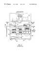
- the apparatusincludes a light source 452 , a processor/controller 404 , a dual carrousel arrangement having an upper carrousel 601 and a lower carrousel 602 which are aligned and spaced apart along a common axis and operated by a rotor 604 , a DC motor 605 having a movable member 603 to move a tray 214 place on one of the carrousels along a common axis toward or away from an array of capillary ends belonging to a capillary cartridge 300 , a detector 408 for detecting, at a window region 130 of the capillaries, the fluorescence emitted by samples migrating along the capillaries, and a computer monitor 406 to view the results of the migration.
- An electrophoretic mediumsuch as a gel, can be introduced into the capillaries via a conduit 606 in preparation
- FIG. 2illustrates a prior art plumbing system in accordance with the above-identified reference, for performing capillary electrophoresis using the device of FIG. 1 .
- FIG. 2shows the integration of a gel syringe 804 5 and an HPLC wash solvent system 807 into the solvent/gel delivery module.
- a solvent manifold 850connects three inlets from the feeder tubes 806 of the solvent containers 801 , 802 , 803 to an outlet.
- Feeder tubes 806 from the solvent containers 801 , 802 , 803are connected to the inlets of the solvent manifold 850 by tubing 860 .
- the inlet of the HPLC pump 807is connected to the outlet of the solvent manifold 850 by tubing 861 and the outlet of the HPLC pump 807 is connected to an inlet of a valve manifold 851 by tubing 862 .
- the valve manifold 851connects two inlets and an outlet.
- One inlet of the valve manifold 851is connected to the gel syringe 804 by tubing 863 and the other inlet of the valve manifold 851 is connected to the outlet of the HPLC pump 807 .
- the outlet of the valve manifold 851is connected to the solvent/gel input port 606 by tubing 864 .
- the controller 404 pictured in FIG. 11causes the valve manifold 851 to select either the inlet connected to the gel syringe 804 or the inlet connected to the HPLC pump 807 . In this manner, gel and solvents are delivered to the capillary cartridge 909 in preparation for capillary gel electrophoresis of samples in microtitre tray 852 .
- the tubing connecting the feeder tubes 806 of the solvent containers 801 , 802 , 803 to the inlets of the solvent manifold 850is standard teflon tubing with a diameter of 1 ⁇ 8 inches.
- the tubing 861 connecting the outlet of the solvent manifold 850 to the inlet of the HPLC pump 807is PEEK tubing with a diameter of ⁇ fraction (1/16) ⁇ inches.
- the tubing 861 connecting the outlet of the solvent manifold 850 to the inlet of the HPLC pump 807 , the tubing 862 connecting the outlet of the HPLC pump 807 to an inlet of the valve manifold 851 , the tubing 863 connecting the gel syringe 804 to an inlet of the valve manifold 851 and the tubing 864 connecting the outlet of the valve manifold 851 to the solvent/gel input portare PEEK tubing with a diameter of ⁇ fraction (1/16) ⁇ inches.
- FIG. 3illustrates a preferred embodiment of capillary cartridge 1180 in accordance with the above-identified application.
- the capillary tubesrun from their first ends 1188 disposed in an electrode/capillary array 1181 .
- the capillary tubesthen run inside multilumen tubing 1183 .
- the multilumen tubingis taught in detail in U.S. patent application Ser. No. 08/866,308, which is incorporated by reference herein.
- the multilumen tubing 1183is held firmly in place by tubing holders 1185 .
- the capillary tubes, without the protection the multilumen tubingpass through an optical detection region 1187 . Beyond the optical detection region 1187 , the capillary tubes have a common termination and are bundled together and cemented into a high pressure T-shaped fitting 1182 made from electrically conductive material, which, during electrophoresis, is connected to electrical ground.
- the tubing holders 1185 and the T-fitting 1182are fixed to a cartridge base 1186 .
- the cartridge base 1186is made from polycarbonate plastic for its dielectric characteristic.
- the base 1186in turn is removably attached to a shuttle 1179 which includes a set of rail couplings 1184 protruding from its bottom. These rail couplings 1184 are arranged so that they fit on to a railing system (not shown in FIG. 18) of the apparatus in FIG. 1 .
- the railing systemallows the shuttle 1184 to move between an in position and out position.
- the base 1186is detached from the shuttle 1179 so that the cartridge 1180 is disposed (or cleaned) and a new (or cleaned) capillary cartridge is attached when the shuttle 1179 is in its out position.
- the combination of the railing system and the shuttle 1179allows the newly attached capillary cartridge to be repeatedly located at the same position as that of the disposed capillary cartridge in relation to a camera and a laser (not shown in FIG. 3) when the shuttle 1179 is in its in position.
- the shuttle 1179extends the length of the base 1186 with an opening to accommodate the electrode/capillary array 1181 ; the shuttle 1179 is attached to the base 1186 by a plurality of removable fasteners 1178 .
- the prior art plumbing system of FIG. 2 and T-fitting of FIG. 3are best suited for capillary gel electrophoresis.
- capillary gel electrophoresisthe gel is fairly viscous, on the order of 50,000 centi-poise. This requires a system which can create pressure sufficient to load gel into the capillaries in preparation for a capillary electrophoresis run, and sufficient to expel the gel from the capillaries during reconditioning.
- buffersare used to load the capillaries in capillary zone electrophoresis (CZE).
- CZEcapillary zone electrophoresis
- These buffershave a viscosity on the order of that of water, i.e., about 1 centi-poise. While the low viscosity of buffers has the advantage of not needing high pressure to load and unload the electrophoretic medium, CZE with buffers does have the disadvantage of capillary siphoning.
- Capillary siphoningis characterized by the buffer solution at one end of the capillaries being completely drawn into the capillaries, thereby depleting the buffer at that one end. Like siphoning of any tubing, this problem occurs when the two ends of the capillaries terminate at different heights. The obvious solution to this problem is to ensure that opposite ends of the capillaries are maintained at the same level. This, however, is less than an ideal solution.
- the present inventionis directed to an automated parallel capillary zone electrophoresis (CZE) system.
- CZEcapillary zone electrophoresis
- the CZE system of the present inventionis realized by modifying the prior art capillary gel electrophoresis (CGE) system of the above-reference prior art. More particularly, the present invention is principally realized by modifying the plumbing at the ends of the capillaries towards which samples in the capillaries migrate.
- CGEcapillary gel electrophoresis
- FIG. 1is a side view of a prior art automated capillary electrophoresis system suitable for capillary gel electrophoresis;
- FIG. 2illustrates a prior art plumbing system for the electrophoresis system of FIG. 1;
- FIG. 3is a side view of a prior art capillary cartridge for use with the electrophoresis system of FIGS. 1 and 2;
- FIG. 4 ashows a preferred embodiment of the present invention for performing capillary zone electrophoresis
- FIG. 4 bshows a sequence of valve settings for the embodiment of FIG. 4 a
- FIG. 5shows a second embodiment of a system in accordance with the present invention
- FIGS. 6 a & 6 bshow two versions of a third embodiment of a system in accordance with the present invention.
- FIG. 7shows intensity images comprising fluorescence data from experimental samples in 96 capillaries simultaneously migrating
- FIGS. 8 a , 8 b & 8 cshows intensity plots for experimental samples migrating in three of the 96 capillaries.
- FIG. 4 ashows a buffer cell 100 connected to a capillary cartridge 102 via a pressure fitting 104 not unlike that shown in FIG. 3 .
- capillary cartridge 102is similar in structure to the capillary cartridge 1180 of FIG. 3, except that capillary cartridge 102 does not include the T-fitting 1182 .
- the buffer cell 100 and its associated hardware shown in FIG. 4areplace the prior art T-fitting 1182 of FIG. 3 and some of the prior art plumbing system seen in FIG. 2 .
- the buffer cell 100has a interior cavity 106 which is which preferably is sealed from the exterior, except for openings discussed below.
- the cellis formed from an acrylic plastic, which is an electrical insulating material. Inner walls of the cell are shaped and sized to provide an interior cavity 106 into which a buffer or other liquid 112 may be introduced.
- the containerhas a capacity of about 100 ml, by volume.
- a high voltage electrode 110 connected to a power supply (not shown)is in contact with the liquid 112 in the cell 100 .
- a power supply(not shown) is in contact with the liquid 112 in the cell 100 .
- the high voltage electrode 110is held at ground, while a non-zero voltage is applied to the second, sample ends 108 of the capillaries, with the polarity of the voltage being determined by the charge-type of the samples being separated.
- the magnitude of the applied voltageis on the order of 10-15 kV, not unlike that used in capillary gel electrophoresis.
- a plurality of conduitscommunicate with the cavity 106 via corresponding valves.
- the valvesare solenoid valves or the like, which can be controlled by computer, much as discussed in the above-identified U.S. application Ser. No. 09/105,888.
- FIG. 4 aeach of the five conduits connected to the cell 100 , whether it is an inlet or an outlet, or serves as both, is shown to have a separate valve. It is understood, however, that one or more of these valves may be internal to equipment connected to the corresponding conduit, rather than being a discrete valve.
- Drain outlet 114 and drain valve 116allow a liquid in the cavity 106 to exit the cell 100 into a waste container (not shown).
- Air conduit 118 and gas (air) release valve 120provide a path from the interior of the cavity 106 to the atmosphere when air valve release 120 is open.
- Pump inlet 122 and pump valve 124provide a path for buffers, solvents and other liquids in containers, such as those indicated by 801 , 802 and 803 , to enter the cell 100 via one or manifolds 850 , under assistance of an HPLC pump 807 , or the like.
- Pressure conduit 126 and pressure valve 128connect a syringe 130 or other pressure applicator to the cavity 106 at a point above the level of liquid 112 therein.
- overflow outlet 132 and overflow valve 134cooperate to provide a passage from the interior of the cavity 106 to a waste container, so as to ensure that the cell 100 does not overfill.
- various valves 116 , 120 , 124 , 128 and 134are shown to be distinct devices, it should be kept in mind that one or more of these valve may be an integral part of another device.
- pump valve 124may be integrally formed as part of HPLC pump 807
- pressure valve 128may be replaced by precisely controlling the syringe's piston 136 by a stepper motor, or the like, under the direction of a controller.
- FIG. 4 adepicts the valve positions for performing steps associated with preparing and conducting electrophoresis on the samples in the capillary tubes of the capillary cartridge 102 .
- the pressure valve 128 and the pump valve 124are closed, and the drain valve 116 and at least one, if not both, of the air valve 120 and the overflow valve 134 are opened. This allows the liquid in the cell to drain via drain conduit 114 .
- the cell 100may be partially filled with a liquid.
- the drain valve 116 and the pressure valve 128are closed, and the pump valve 124 and at least one, if not both, of the air valve 120 and overflow valve 134 open.
- the pump 807is then operated to introduce a selected one of the liquids in containers 801 , 802 , 803 into the cell 100 . Because the pump introduces liquid into the reservoir and, because at least one of the air valve 120 and the overflow valve 132 is open, the liquid is not forced into the capillaries. However, the pump is controlled to turn off when the liquid reaches a predetermined level within the cell.
- a cleaning solution, or the like, present in one or more of the containers 801 , 802 , 803is forced into the cell 100 , into the cell ends 107 of the capillary tubes, and out the sample ends 108 of the capillary tubes.
- the pump valve 124is open while all the other valves are closed.
- the HPLC pump 807when the HPLC pump 807 operates, it forces liquid into the cell 106 , increasing the pressure therein. The increased pressure forces the cleaning solution into the cell ends 107 , through the capillary tubes and out the sample ends 108 .
- the pump valvemay be closed, and the cell 100 drained, as discussed above.
- the cellcan be filled with buffer to a predetermined level by selecting the appropriate container 801 , 802 , 803 with the manifold 850 , and operating the pump 807 with the drain valve 116 and the pressure valve 128 closed, and the pump valve 124 and at least one, if not both, of the air valve 120 and overflow valve 134 open.
- the predetermine level of buffershould exceed the level of the bundle of capillary cell ends 107 .
- buffermay be loaded into the capillaries. For this, the only the pump valve 124 is left open, and all other valves are closed. The buffer enters the capillary cell ends 107 , thereby forcing any material within the capillary tubes out the capillary sample ends 108 into a waste container (not shown), and loading the capillary tubes with buffer.
- the cell 100is filled with buffer to just below the level of the overflow conduit 132 , yet above the level of the capillary cell ends.
- the overflow conduit 132is at about the 60% fill level and so the cell 100 , having a capacity of 100 ml, contains approximately 60 ml of buffer.
- bufferrather than a cleaning solvent
- the sample ends 108are first dipped into wells of a microtitre tray of standard size, such as those having a rectangular array of 8 rows of 12 wells, or those having 16 rows of 24 wells.
- the wellscontain the samples to be electrophoresced.
- the samplescan be introduced into the sample ends 108 of the capillaries in one of two ways.
- One wayis electro-kinetic injection wherein a voltage differential is applied between the sample ends and the cell ends of the capillaries so as to cause a portion of the sample to enter the sample ends.
- the air valve 120is kept open keep the reservoir 100 at atmospheric pressure, equilibrated with the cell ends 107 of the capillary.
- the electro-osmotic flowcauses sample enter the capillary sample ends 108 .
- a second way in which to load samples into the sample ends 108 of the capillariesis by hydrodynamic injection.
- air valve 120is opened and all other valves are closed to equilibrate both ends of the capillaries with atmospheric pressure. After equilibration, the air valve 120 is also closed, and so no valves are left open.
- the plunger 136 of the syringe 130is pulled back by a predetermined volume. This causes the air above the liquid level in the cell to expand into a slightly greater volume and thereby create a vacuum, or negative pressure.
- the pressure valve 128is opened, thereby applying this negative pressure to the surface of the buffer 112 in the cell 100 . Due to the negative pressure, a small amount of sample (or other substance in each of the wells of the microtitre tray) is sucked in at each of the capillary sample ends.
- the pulling volume of the syringecontrols the degree of negative pressure or vacuum.
- the plungeris pulled back by an amount sufficient to displace about 2 ml.
- the precision of the negative pressurecan be controlled to about 0.001 atm.
- the sample trayis preferably replaced by a buffer tray in preparation for electrophoresis.
- Replacing the sample trays with buffer trayshelps ensure than excess sample is not taken into the capillary tubes, and also ensures that both ends of the capillary tubes are inserted into buffer.
- electrophoresiscan take place in either a static mode, or a dynamic mode.
- the pump 807In the static mode, the pump 807 is not operational and only the air valve 120 , or the overflow valve 134 , or both, are open, with the remaining valves closed. Under these conditions, the buffer in the cell 112 is substantially stagnant during electrophoresis.
- the pressure valve 128is closed, and all other valves are open, and the pump is operational, with buffer continuously being pumped into the cell through the pump inlet 122 and exiting the cell via drain outlet 114 .
- Thisensures that fresh buffer bathes the capillary cell ends during electrophoresis while older buffer drains from the cell.
- Samples which have completed migrating from the sample end all the way to the cell endare also drained through drain outlet 114 and drain valve 116 .
- air conduit 118 and air valve 120are open, the atmospheric pressure at both ends of the capillaries is equalized, thereby counteracting the siphoning effect, especially when the capillary ends are at the same height.
- the dynamic modein which there is continuous flushing of the cell 100 , provides several advantages.
- continuously providing fresh buffer solution to the capillary cell endsremoves charge depletion during electrophoresis.
- Charge depletionhappens when anion and cation layers build up around the electrode, thereby resulting in a voltage drop between these layers which, in turn, reduces the voltage drop across the capillary tubes for separation.
- Flowing bufferhelps retard the formation of such layers so that sample separation is more reproducible from run to run.
- a second advantage to constant flushingis that it assists in removing fluids and contaminants introduced into the cell by electro-osmotic flow (EOF) during electrophoresis.
- EEFelectro-osmotic flow
- EOFis a continuous pumping process which brings small amounts of sample-laden buffer into the cell. This can cause a change in buffer conductivity during electrophoresis. Constant flushing helps mitigate the problem of a solute-imbalance.
- Sensors and feedback control systems connected to the pump and to the pump and drain valvescan ensure that the liquid level in the cell is maintained at a predetermined level.
- a third advantage to continuous flushingis that it reduces the time spent cleaning the capillary tubes between runs. Because fresh buffer is constantly being introduced into the cell in the dynamic mode, one need spend as much time rinsing out the cell, upon conclusion of each run.
- a fourth advantage to continuous flushingis that it removes air bubbles which otherwise collect around the capillary cell ends 107 during electrophoresis. Such removal is believed to be brought about by the buffer flowing past this area.
- a voltage differential of 10 kV across the capillary ends and borate buffer at a pH of 10.5, EOF speedis about 12 cm/min. This causes the liquid volume of the cell to increase at the rate of about 53 ⁇ /min. If a drain is provided, the buffer must be replenished, as needed. In the preferred embodiment, only about 1 ml/min of fresh buffer is introduced into the cell while the drain valve is opened during electrophoresis.
- the primary requirements for carrying out CZE in accordance with the present inventionare that a cell be provided, the cell having a liquid therein with the capillary cell ends terminating in said liquid, and that some mechanism be provided for creating a vacuum, or suction effect, at the capillary cell ends so as to draw samples into capillary sample ends.
- FIG. 5presents another embodiment in accordance with the present invention.
- a sealed, or at least sealable, cell 100 partially filled with a liquid 112is provided.
- the capillary cell ends 107terminate in this liquid 112 .
- An air syringe 130 and an HPLC pump 807are also provided.
- sampleis introduced into the capillary sample ends 108 , as depicted by arrow A 2 .
- conduits for drain, air release and overflowmay also be provided.
- FIG. 6 apresents yet another embodiment in accordance with the present invention.
- this embodimentwhich is similar to embodiment of FIG. 5, the entire cell and the syringe are filled with liquid and no air (or other gas) is used. Unlike air, liquid is incompressible, and so there is neither a time delay nor a variation in volume, between pulling the syringe plunger and the introduction of samples into the capillary sample ends. This means that the syringe must be much more precisely controlled in the embodiment of FIG. 6 a than in the embodiment of FIG. 5 .
- a micro-syringes operated by high-precision stepper motors, or the likeis used to ensure that only a small quantity of sample, about 0.1 ⁇ l or so, per capillary, is introduced into each of the capillary second ends.
- a micro-syringes operated by high-precision stepper motors, or the likeis used to ensure that only a small quantity of sample, about 0.1 ⁇ l or so, per capillary, is introduced into each of the capillary second ends.
- FIG. 6 apresents still another embodiment in accordance with the present invention.
- the syringeis replaced by a narrow-diameter drain outlet 140 controlled by a valve 142 situated at a vertical position lower than that of the capillary sample ends 108 .
- gravityis used to cause a negative pressure.
- the valve 142With the pump off, when the valve 142 is opened, liquid drains through the conduit 140 as indicated by arrow A 3 . This siphons liquid into the capillary sample ends, as indicated by arrow A 4 .
- valves between the pump and the cellare not shown; it is understood, however, that such valves may be integral with the pump. Similarly, no such valves are shown between the syringe and the cell.
- the syringe plungermay be restrained and controlled by a motor so as to exert sufficient force in the appropriate direction, as dictated by a microprocessor or other controller.
- FIGS. 6 a and 6 bit is noted that since only a very minute quantity of liquid is introduced from the capillary tubes into the cell, there is no appreciable increase in pressure within the cell, which is substantially able to accommodate the added amount.
- capillary zone electrophoresiswas carried out simultaneously in 96 capillaries using a device substantially arranged as shown in FIG. 4 a .
- About 60 ml of bufferwas introduced into a 100 ml cell.
- the buffer usedwas a 10 mM borate solution in de-ionized water, adjusted to a pH 10.5 with NaOH.
- the viscosity of the bufferwas almost the same as that of water.
- capillarieseach having a length of about 50 cm, and ID of 50 ⁇ m and an 150 OD ⁇ m, available from Polymcro Technology of Phoenix, AZ were used.
- a window regionwas burned into each capillary using a hot wire at a point approximately 10 cm from one end of the capillaries, thereby providing an effective migration distance of about 40 cm from the sample end to the window region at which sample detection would take place.
- the capillarieswere arranged substantially parallel to one another in a ribbon-like arrangement. More specifically, for most of their length from the sample ends to the window, the capillaries were spaced apart from one another by about 150 ⁇ m and, at the window region, were spaced apart by about 300 ⁇ m.
- the cell ends of the 96 capillarieswere bound together as a bundle with Torr Seal, available from Varian Vacuum Products of Lexington, Mass. This bundle was connected to the cell shown in FIG. 4 a with a Swagelock fitting, with the capillaries being in communication with the buffer. Meanwhile, the sample ends of the capillaries formed a two-dimensional array with a spacing corresponding to that of the wells of an 8 ⁇ 12 microtitre tray of standard size.
- a 3 ⁇ l samplewas introduced into each of the wells of an 8 ⁇ 12 microtitre tray.
- the samplecomprised a protein cluster separated from among a multitude of such clusters in a protein mixture extracted from bacteria.
- the proteinswere labeled with fluorescein dye, which has its absorption maximum at 495 nm.
- the sample ends of the capillarieswere inserted into corresponding wells of the microtitre tray, in contact with the sample therein. Samples in each of the 96 wells were then hydrodynamically injected into the sample ends of the capillaries. This was performed by creating a vacuum by pulling on the syringe plunger to displace a 3 ml volume with all valves closed, and holding the plunger in place.
- the pressure valvewas opened, thereby causing a negative pressure at the air-buffer interface on the surface of the buffer in the cell.
- the pressure valvewas opened for about 20 seconds, permitting sufficient time for sample to be sucked into each of the capillary sample ends.
- the air valvewas opened to alleviate the negative pressure and stop further hydrodynamic injection of sample.
- microtitre tray containing sampleswas replaced with a microtitre tray containing buffer, in preparation for electrophoresis.
- a voltage differential of 10 kVwas applied for about 10 minutes across the 50 cm-long capillaries, thereby providing an electric field of 200 v/cm and causing the samples to migrate under electro-osmotic flow, along with the buffer.
- An all-line Argon-ion laseravailable from Spectra-Physics of Mountain View, Calif., and having an emissions peak not far from 495 nm, was used to illuminate the capillaries substantially at right angles thereto at the window region during electrophoresis.
- a CCD cameraavailable from PixelView of Beaverton, Oregon, was used to detect the fluorescence of the samples as they passed through the window region of the capillaries.
- the camerawas set up substantially as disclosed in co-owned allowed U.S. application Ser. No. 09/084,236, also published as WO 99/32877.
- FIG. 7shows the fluorescence intensities at 530 ⁇ 8 nm, as a function of time, of the samples in the 96 capillaries.
- the abscissax-axis
- the ordinatey-axis
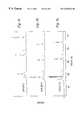
- FIGS. 8 a , 8 b and 8 cshow plots of relative intensities for edge and center capillaries (capillary nos. 1 , 48 and 96 ) in the array, as a function of time.
- the abscissax-axis
- the ordinatey-axis
- the intensity contoursare substantially the same, exhibiting similar peaks from each capillary, albeit at slightly different migration times for each capillary.
- CZEcan be used to separate proteins in a buffer having a predetermined pH.
- CZEcan be used for human growth hormone separation, Ca++ binding protein separation, and recombinant human erythroprotein protein separation, among others.
- the separation mechanism in CZEis based on the ratio of the net charge to the size of the proteins.
- the net chargecan be of either polarity, depending on the buffer pH and the protein's structure. Electro-osmotic flow of the buffer in the capillaries sweeps neutral molecules, as well as charged proteins, toward the detection window.
- the bufferpreferably has a viscosity about the same as that of water.
- the present inventionmay also be used in other capillary electrophoresis settings in which the separation media has low viscosity, on the order of 1-150, and more preferably on the order of 1-50, centipoise. At these viscosities, the separation media can be pumped into the capillaries under pressure without damage to the capillaries or other components of the system, and the samples injected hydrodynamically. A number of these other approaches and applications are now discussed.
- Sodium Dodecyl Sulfate(SDS)-type Capillary Gel(CGE)/NGE (Non-Gel)ElectrophoresisIn this approach, the proteins are bound with the surfactant SDS to form negatively charged aggregates.
- a polymer-based sieving matrixsuch as polyethylene oxide(PEO), preferably kept at a low pH to extend the lifetime of the capillaries, is used as the separation medium.
- PEOpolyethylene oxide
- CGE with a low-viscosity separation mediasuch as polyvinylpyrrolidone (PVP), which has a viscosity of 1-25 centipoise when in a weight percentage of 0.1-5%, can be used for DNA separation, as reported in Gao & Yeung, Anal. Chem., 1998, v. 70, pp. 1382-1388.
- PVPpolyvinylpyrrolidone
- CIEFCapillary Iso-Electric Focusing
- ACEAffinity Capillary Electrophoresis in which proteins are separated on the basis of specific bonding to other molecules in a separation medium having a viscosity of about 5-50 centipoise may also be performed using the device and method of the present invention.
- Micellular Electrokinetic Capillary Chromotography(MEKC),in which compounds are separated based on their hydro-phobicity in a separation medium having a viscosity of about 5-50 centipoise may also be performed using the device and method of the present invention. Such an approach would be espcially useful in separating non-charged species.
- Capillary Isotachphoresiswhich is used for incapillary protein pre-concentration, immediately preceding CZE, may be performed using the device and method of the present invention.
Landscapes
- Chemical & Material Sciences (AREA)
- Life Sciences & Earth Sciences (AREA)
- Health & Medical Sciences (AREA)
- Molecular Biology (AREA)
- Chemical Kinetics & Catalysis (AREA)
- Electrochemistry (AREA)
- General Health & Medical Sciences (AREA)
- Analytical Chemistry (AREA)
- Biochemistry (AREA)
- General Physics & Mathematics (AREA)
- Physics & Mathematics (AREA)
- Immunology (AREA)
- Pathology (AREA)
- Organic Chemistry (AREA)
- Medicinal Chemistry (AREA)
- Genetics & Genomics (AREA)
- Biophysics (AREA)
- Proteomics, Peptides & Aminoacids (AREA)
- General Chemical & Material Sciences (AREA)
- Sampling And Sample Adjustment (AREA)
- Investigating, Analyzing Materials By Fluorescence Or Luminescence (AREA)
- Automatic Analysis And Handling Materials Therefor (AREA)
- Investigating Or Analysing Biological Materials (AREA)
Abstract
Description
Claims (22)
Priority Applications (10)
| Application Number | Priority Date | Filing Date | Title |
|---|---|---|---|
| US09/388,125US6352633B1 (en) | 1999-08-31 | 1999-08-31 | Automated parallel capillary electrophoresis system with hydrodynamic sample injection |
| PCT/US2000/023709WO2001016587A1 (en) | 1999-08-31 | 2000-08-29 | Automated parallel capillary electrophoresis system with hydrodynamic sample injection |
| CA002383912ACA2383912C (en) | 1999-08-31 | 2000-08-29 | Automated parallel capillary electrophoresis system with hydrodynamic sample injection |
| JP2001520093AJP2003508749A (en) | 1999-08-31 | 2000-08-29 | Automatic parallel capillary zone electrophoresis analysis system with hydrodynamic sample injection |
| EP00959564AEP1212608A4 (en) | 1999-08-31 | 2000-08-29 | Automated parallel capillary electrophoresis system with hydrodynamic sample injection |
| US10/011,977US6953521B2 (en) | 1999-08-31 | 2001-12-11 | Automated parallel capillary electrophoresis system with hydrodynamic sample injection |
| US11/204,773US7459070B2 (en) | 1999-08-31 | 2005-08-15 | Automated parallel capillary electrophoresis system with hydrodynamic sample injection |
| US12/290,087US20090090630A1 (en) | 1999-08-31 | 2008-10-27 | Automated parallel capillary electrophoresis system with hydrodynamic sample injection |
| US12/634,661US20100147692A1 (en) | 1999-08-31 | 2009-12-09 | Automated Parallel Capillary Electrophoresis System with Hydrodynamic Sample Injection |
| US13/048,846US20110220508A1 (en) | 1999-08-31 | 2011-03-15 | Automated Parallel Capillary Electrophoresis System with Hydrodynamic Sample Injection |
Applications Claiming Priority (1)
| Application Number | Priority Date | Filing Date | Title |
|---|---|---|---|
| US09/388,125US6352633B1 (en) | 1999-08-31 | 1999-08-31 | Automated parallel capillary electrophoresis system with hydrodynamic sample injection |
Related Parent Applications (1)
| Application Number | Title | Priority Date | Filing Date |
|---|---|---|---|
| US10/011,977ContinuationUS6953521B2 (en) | 1999-08-31 | 2001-12-11 | Automated parallel capillary electrophoresis system with hydrodynamic sample injection |
Related Child Applications (2)
| Application Number | Title | Priority Date | Filing Date |
|---|---|---|---|
| US10/011,977ContinuationUS6953521B2 (en) | 1999-08-31 | 2001-12-11 | Automated parallel capillary electrophoresis system with hydrodynamic sample injection |
| US11/204,773ContinuationUS7459070B2 (en) | 1999-08-31 | 2005-08-15 | Automated parallel capillary electrophoresis system with hydrodynamic sample injection |
Publications (1)
| Publication Number | Publication Date |
|---|---|
| US6352633B1true US6352633B1 (en) | 2002-03-05 |
Family
ID=23532811
Family Applications (6)
| Application Number | Title | Priority Date | Filing Date |
|---|---|---|---|
| US09/388,125Expired - LifetimeUS6352633B1 (en) | 1999-08-31 | 1999-08-31 | Automated parallel capillary electrophoresis system with hydrodynamic sample injection |
| US10/011,977Expired - LifetimeUS6953521B2 (en) | 1999-08-31 | 2001-12-11 | Automated parallel capillary electrophoresis system with hydrodynamic sample injection |
| US11/204,773Expired - LifetimeUS7459070B2 (en) | 1999-08-31 | 2005-08-15 | Automated parallel capillary electrophoresis system with hydrodynamic sample injection |
| US12/290,087AbandonedUS20090090630A1 (en) | 1999-08-31 | 2008-10-27 | Automated parallel capillary electrophoresis system with hydrodynamic sample injection |
| US12/634,661AbandonedUS20100147692A1 (en) | 1999-08-31 | 2009-12-09 | Automated Parallel Capillary Electrophoresis System with Hydrodynamic Sample Injection |
| US13/048,846AbandonedUS20110220508A1 (en) | 1999-08-31 | 2011-03-15 | Automated Parallel Capillary Electrophoresis System with Hydrodynamic Sample Injection |
Family Applications After (5)
| Application Number | Title | Priority Date | Filing Date |
|---|---|---|---|
| US10/011,977Expired - LifetimeUS6953521B2 (en) | 1999-08-31 | 2001-12-11 | Automated parallel capillary electrophoresis system with hydrodynamic sample injection |
| US11/204,773Expired - LifetimeUS7459070B2 (en) | 1999-08-31 | 2005-08-15 | Automated parallel capillary electrophoresis system with hydrodynamic sample injection |
| US12/290,087AbandonedUS20090090630A1 (en) | 1999-08-31 | 2008-10-27 | Automated parallel capillary electrophoresis system with hydrodynamic sample injection |
| US12/634,661AbandonedUS20100147692A1 (en) | 1999-08-31 | 2009-12-09 | Automated Parallel Capillary Electrophoresis System with Hydrodynamic Sample Injection |
| US13/048,846AbandonedUS20110220508A1 (en) | 1999-08-31 | 2011-03-15 | Automated Parallel Capillary Electrophoresis System with Hydrodynamic Sample Injection |
Country Status (5)
| Country | Link |
|---|---|
| US (6) | US6352633B1 (en) |
| EP (1) | EP1212608A4 (en) |
| JP (1) | JP2003508749A (en) |
| CA (1) | CA2383912C (en) |
| WO (1) | WO2001016587A1 (en) |
Cited By (9)
| Publication number | Priority date | Publication date | Assignee | Title |
|---|---|---|---|---|
| US20020040850A1 (en)* | 1999-08-31 | 2002-04-11 | Spectrumedix Corporation | Automated parallel capillary electrophoresis system with hydrodynamic sample injection |
| US20040070758A1 (en)* | 2002-10-11 | 2004-04-15 | Kenseth Jeremy R. | Multiplexed, absorbance-based capillary electrophoresis system and method |
| WO2004079356A1 (en)* | 2003-02-28 | 2004-09-16 | Combisep Inc. | Multiplexed absorbance-based capillary electrophoresis system and method |
| US20040188255A1 (en)* | 2003-02-28 | 2004-09-30 | Combisep, Inc. | Multiplexed, absorbance-based capillary electrophoresis system and method |
| US20060070880A1 (en)* | 2004-08-31 | 2006-04-06 | Applera Corporation | Methods and apparatus for manipulating separation media |
| WO2006119707A1 (en)* | 2005-05-11 | 2006-11-16 | Accelergy Shanghai R & D Center Co., Ltd | A high throughput detecting system and method thereof |
| US20080116073A1 (en)* | 2006-11-22 | 2008-05-22 | Hitachi High-Technologies Corporation | Electrophoretic apparatus |
| CN102435659A (en)* | 2010-08-25 | 2012-05-02 | 爱科来株式会社 | Analysis Apparatus and Analysis Method |
| CN109725042A (en)* | 2017-10-30 | 2019-05-07 | 爱科来株式会社 | The method of transfer tube |
Families Citing this family (29)
| Publication number | Priority date | Publication date | Assignee | Title |
|---|---|---|---|---|
| US8071384B2 (en) | 1997-12-22 | 2011-12-06 | Roche Diagnostics Operations, Inc. | Control and calibration solutions and methods for their use |
| US7986729B2 (en) | 1999-10-28 | 2011-07-26 | Lightwaves Systems, Inc. | High bandwidth data transport system |
| US7545868B2 (en) | 2001-03-20 | 2009-06-09 | Lightwaves Systems, Inc. | High bandwidth data transport system |
| US8766773B2 (en) | 2001-03-20 | 2014-07-01 | Lightwaves Systems, Inc. | Ultra wideband radio frequency identification system, method, and apparatus |
| US7983349B2 (en) | 2001-03-20 | 2011-07-19 | Lightwaves Systems, Inc. | High bandwidth data transport system |
| WO2003087773A2 (en)* | 2002-04-12 | 2003-10-23 | Amersham Biosciences (Sv) Corp | Multiplexed capillary electrophoresis systems |
| US7597793B2 (en) | 2003-06-20 | 2009-10-06 | Roche Operations Ltd. | System and method for analyte measurement employing maximum dosing time delay |
| US7645421B2 (en) | 2003-06-20 | 2010-01-12 | Roche Diagnostics Operations, Inc. | System and method for coding information on a biosensor test strip |
| US7718439B2 (en) | 2003-06-20 | 2010-05-18 | Roche Diagnostics Operations, Inc. | System and method for coding information on a biosensor test strip |
| US8058077B2 (en) | 2003-06-20 | 2011-11-15 | Roche Diagnostics Operations, Inc. | Method for coding information on a biosensor test strip |
| US8148164B2 (en) | 2003-06-20 | 2012-04-03 | Roche Diagnostics Operations, Inc. | System and method for determining the concentration of an analyte in a sample fluid |
| US7645373B2 (en) | 2003-06-20 | 2010-01-12 | Roche Diagnostic Operations, Inc. | System and method for coding information on a biosensor test strip |
| US8206565B2 (en) | 2003-06-20 | 2012-06-26 | Roche Diagnostics Operation, Inc. | System and method for coding information on a biosensor test strip |
| US7604721B2 (en) | 2003-06-20 | 2009-10-20 | Roche Diagnostics Operations, Inc. | System and method for coding information on a biosensor test strip |
| US7452457B2 (en) | 2003-06-20 | 2008-11-18 | Roche Diagnostics Operations, Inc. | System and method for analyte measurement using dose sufficiency electrodes |
| US7569126B2 (en) | 2004-06-18 | 2009-08-04 | Roche Diagnostics Operations, Inc. | System and method for quality assurance of a biosensor test strip |
| US7556723B2 (en) | 2004-06-18 | 2009-07-07 | Roche Diagnostics Operations, Inc. | Electrode design for biosensor |
| TWI358539B (en)* | 2008-12-09 | 2012-02-21 | Univ Nat Taiwan | Integrated electrophoresis device and operation th |
| CN101750450B (en)* | 2008-12-17 | 2013-03-27 | 中国科学院大连化学物理研究所 | Automatic sampling device for array capillary electrophoresis |
| JP2012525591A (en)* | 2009-04-27 | 2012-10-22 | プロテイン・デイスカバリー・インコーポレーテツド | Programmable electrophoresis notch filter system and method |
| JP2011102722A (en)* | 2009-11-10 | 2011-05-26 | Sharp Corp | Gel filling device, and gel forming method using the same |
| JP5830230B2 (en)* | 2010-07-20 | 2015-12-09 | アークレイ株式会社 | Analysis apparatus and analysis method |
| WO2012135849A1 (en)* | 2011-04-01 | 2012-10-04 | Life Technologies Corporation | Computer - controlled gel electrophoresis system |
| AU2013302301B2 (en)* | 2012-08-13 | 2017-06-15 | University Of Tasmania | Electrophoretic separation of analytes |
| US11746388B2 (en)* | 2017-03-07 | 2023-09-05 | University Of Notre Dame Du Lac | Systems and method for electrophoretic fractionation of the microbiome |
| USD919833S1 (en) | 2019-03-06 | 2021-05-18 | Princeton Biochemicals, Inc | Micro valve for controlling path of fluids in miniaturized capillary connections |
| JP1671133S (en)* | 2020-03-04 | 2020-10-26 | ||
| JP1671132S (en)* | 2020-03-04 | 2020-10-26 | ||
| JP1671134S (en)* | 2020-03-04 | 2020-10-26 |
Citations (25)
| Publication number | Priority date | Publication date | Assignee | Title |
|---|---|---|---|---|
| GB2113903A (en) | 1982-01-12 | 1983-08-10 | Standard Telephones Cables Ltd | Cable manufacture |
| EP0257855A2 (en) | 1986-08-04 | 1988-03-02 | E.I. Du Pont De Nemours And Company | Cable having a corrugated septum |
| WO1989004966A1 (en) | 1987-11-25 | 1989-06-01 | Norberto Guzman | Automated capillary electrophoresis apparatus |
| DE9011484U1 (en) | 1990-08-07 | 1990-10-11 | Ernst & Engbring GmbH, 4353 Oer-Erkenschwick | Electronic cables |
| US5085757A (en) | 1987-11-25 | 1992-02-04 | Northeastern University | Integrated temperature control/alignment system for high performance capillary electrophoretic apparatus |
| US5198091A (en) | 1988-04-29 | 1993-03-30 | Beckman Instruments, Inc. | Capillary cartridge for electrophoresis |
| US5207886A (en) | 1988-02-16 | 1993-05-04 | Applied Biosystems, Inc. | Capillary electrophoresis |
| US5235409A (en) | 1991-08-13 | 1993-08-10 | Varian Associates, Inc. | Optical detection system for capillary separation columns |
| US5240585A (en) | 1992-07-14 | 1993-08-31 | Hewlett-Packard Company | Conductive bridge for external control of electroosmotic flow |
| US5274240A (en) | 1990-01-12 | 1993-12-28 | The Regents Of The University Of California | Capillary array confocal fluorescence scanner and method |
| US5277780A (en) | 1991-09-13 | 1994-01-11 | Hitachi, Ltd. | Electrophoresis gel migration apparatus |
| US5332480A (en) | 1993-06-16 | 1994-07-26 | University Of Iowa Research Foundation | Capillary bed electrophoresis |
| US5332481A (en) | 1991-01-29 | 1994-07-26 | Beckman Instruments, Inc. | Capillary electrophoresis using replaceable gels |
| US5356525A (en) | 1993-04-16 | 1994-10-18 | Beckman Instruments, Inc. | Sample handling system |
| WO1994029713A1 (en) | 1993-06-03 | 1994-12-22 | Beckman Instruments, Inc. | Capillary and capillary retaining system |
| WO1994029712A1 (en) | 1993-06-03 | 1994-12-22 | University Of Alberta | Multiple capillary biochemical analyzer |
| US5413686A (en)* | 1992-07-17 | 1995-05-09 | Beckman Instruments, Inc. | Multi-channel automated capillary electrophoresis analyzer |
| US5436130A (en) | 1992-03-19 | 1995-07-25 | The Regents Of The University Of California | Multiple tag labeling method for DNA sequencing |
| US5447611A (en)* | 1989-05-01 | 1995-09-05 | Lauer; Hermanus H. | Vacuum injection capillary electrophoresis |
| US5498324A (en) | 1993-02-05 | 1996-03-12 | Iowa State University Research Foundation, Inc. | Multiplexed fluorescence detector system for capillary electrophoresis |
| EP0723149A2 (en) | 1995-01-19 | 1996-07-24 | Hitachi, Ltd. | Capillary array electrophoresis system |
| US5605666A (en) | 1993-04-16 | 1997-02-25 | Beckman Instruments, Inc. | Capillary retaining system |
| US5635050A (en) | 1995-08-23 | 1997-06-03 | Beckman Instruments, Inc. | Electrophoretic system including means for replacing separation medium |
| US5730850A (en)* | 1993-04-23 | 1998-03-24 | Hitachi, Ltd. | Capillary array electrophoresis system |
| WO1999000664A1 (en) | 1997-06-30 | 1999-01-07 | Spectrumedix Corporation | Automated parallel capillary electrophoretic system |
Family Cites Families (9)
| Publication number | Priority date | Publication date | Assignee | Title |
|---|---|---|---|---|
| GB2255781B (en)* | 1991-02-15 | 1995-01-18 | Reactive Ind Inc | Adhesive system |
| US5516409A (en)* | 1991-02-28 | 1996-05-14 | Hitachi, Ltd. | DNA detector and DNA detection method |
| US5302264A (en)* | 1992-09-02 | 1994-04-12 | Scientronix, Inc. | Capillary eletrophoresis method and apparatus |
| US5290418A (en)* | 1992-09-24 | 1994-03-01 | Applied Biosystems, Inc. | Viscous electrophoresis polymer medium and method |
| US5582705A (en)* | 1995-05-19 | 1996-12-10 | Iowa State University Research Foundation, Inc. | Multiplexed capillary electrophoresis system |
| US5885430A (en)* | 1996-10-04 | 1999-03-23 | Spectrumedix Corporation | Capillary tube holder for an electrophoretic apparatus |
| US6027627A (en)* | 1997-06-30 | 2000-02-22 | Spectrumedix Corporation | Automated parallel capillary electrophoretic system |
| US6352633B1 (en)* | 1999-08-31 | 2002-03-05 | Spectrumedix Corporation | Automated parallel capillary electrophoresis system with hydrodynamic sample injection |
| US6766817B2 (en)* | 2001-07-25 | 2004-07-27 | Tubarc Technologies, Llc | Fluid conduction utilizing a reversible unsaturated siphon with tubarc porosity action |
- 1999
- 1999-08-31USUS09/388,125patent/US6352633B1/ennot_activeExpired - Lifetime
- 2000
- 2000-08-29CACA002383912Apatent/CA2383912C/ennot_activeExpired - Fee Related
- 2000-08-29JPJP2001520093Apatent/JP2003508749A/enactivePending
- 2000-08-29EPEP00959564Apatent/EP1212608A4/ennot_activeWithdrawn
- 2000-08-29WOPCT/US2000/023709patent/WO2001016587A1/ennot_activeApplication Discontinuation
- 2001
- 2001-12-11USUS10/011,977patent/US6953521B2/ennot_activeExpired - Lifetime
- 2005
- 2005-08-15USUS11/204,773patent/US7459070B2/ennot_activeExpired - Lifetime
- 2008
- 2008-10-27USUS12/290,087patent/US20090090630A1/ennot_activeAbandoned
- 2009
- 2009-12-09USUS12/634,661patent/US20100147692A1/ennot_activeAbandoned
- 2011
- 2011-03-15USUS13/048,846patent/US20110220508A1/ennot_activeAbandoned
Patent Citations (26)
| Publication number | Priority date | Publication date | Assignee | Title |
|---|---|---|---|---|
| GB2113903A (en) | 1982-01-12 | 1983-08-10 | Standard Telephones Cables Ltd | Cable manufacture |
| EP0257855A2 (en) | 1986-08-04 | 1988-03-02 | E.I. Du Pont De Nemours And Company | Cable having a corrugated septum |
| WO1989004966A1 (en) | 1987-11-25 | 1989-06-01 | Norberto Guzman | Automated capillary electrophoresis apparatus |
| US5085757A (en) | 1987-11-25 | 1992-02-04 | Northeastern University | Integrated temperature control/alignment system for high performance capillary electrophoretic apparatus |
| US5207886A (en) | 1988-02-16 | 1993-05-04 | Applied Biosystems, Inc. | Capillary electrophoresis |
| US5198091A (en) | 1988-04-29 | 1993-03-30 | Beckman Instruments, Inc. | Capillary cartridge for electrophoresis |
| US5447611A (en)* | 1989-05-01 | 1995-09-05 | Lauer; Hermanus H. | Vacuum injection capillary electrophoresis |
| US5274240A (en) | 1990-01-12 | 1993-12-28 | The Regents Of The University Of California | Capillary array confocal fluorescence scanner and method |
| DE9011484U1 (en) | 1990-08-07 | 1990-10-11 | Ernst & Engbring GmbH, 4353 Oer-Erkenschwick | Electronic cables |
| US5332481A (en) | 1991-01-29 | 1994-07-26 | Beckman Instruments, Inc. | Capillary electrophoresis using replaceable gels |
| US5235409A (en) | 1991-08-13 | 1993-08-10 | Varian Associates, Inc. | Optical detection system for capillary separation columns |
| US5277780A (en) | 1991-09-13 | 1994-01-11 | Hitachi, Ltd. | Electrophoresis gel migration apparatus |
| US5436130A (en) | 1992-03-19 | 1995-07-25 | The Regents Of The University Of California | Multiple tag labeling method for DNA sequencing |
| US5240585A (en) | 1992-07-14 | 1993-08-31 | Hewlett-Packard Company | Conductive bridge for external control of electroosmotic flow |
| US5413686A (en)* | 1992-07-17 | 1995-05-09 | Beckman Instruments, Inc. | Multi-channel automated capillary electrophoresis analyzer |
| US5498324A (en) | 1993-02-05 | 1996-03-12 | Iowa State University Research Foundation, Inc. | Multiplexed fluorescence detector system for capillary electrophoresis |
| US5605666A (en) | 1993-04-16 | 1997-02-25 | Beckman Instruments, Inc. | Capillary retaining system |
| US5417925A (en) | 1993-04-16 | 1995-05-23 | Beckman Instruments, Inc. | Capillary and capillary retaining system |
| US5356525A (en) | 1993-04-16 | 1994-10-18 | Beckman Instruments, Inc. | Sample handling system |
| US5730850A (en)* | 1993-04-23 | 1998-03-24 | Hitachi, Ltd. | Capillary array electrophoresis system |
| WO1994029712A1 (en) | 1993-06-03 | 1994-12-22 | University Of Alberta | Multiple capillary biochemical analyzer |
| WO1994029713A1 (en) | 1993-06-03 | 1994-12-22 | Beckman Instruments, Inc. | Capillary and capillary retaining system |
| US5332480A (en) | 1993-06-16 | 1994-07-26 | University Of Iowa Research Foundation | Capillary bed electrophoresis |
| EP0723149A2 (en) | 1995-01-19 | 1996-07-24 | Hitachi, Ltd. | Capillary array electrophoresis system |
| US5635050A (en) | 1995-08-23 | 1997-06-03 | Beckman Instruments, Inc. | Electrophoretic system including means for replacing separation medium |
| WO1999000664A1 (en) | 1997-06-30 | 1999-01-07 | Spectrumedix Corporation | Automated parallel capillary electrophoretic system |
Cited By (20)
| Publication number | Priority date | Publication date | Assignee | Title |
|---|---|---|---|---|
| US20100147692A1 (en)* | 1999-08-31 | 2010-06-17 | Life Technologies Corporation | Automated Parallel Capillary Electrophoresis System with Hydrodynamic Sample Injection |
| US20060091011A1 (en)* | 1999-08-31 | 2006-05-04 | Changsheng Liu | Automated parallel capillary electrophoresis system with hydrodynamic sample injection |
| US20110220508A1 (en)* | 1999-08-31 | 2011-09-15 | Life Technologies Corporation | Automated Parallel Capillary Electrophoresis System with Hydrodynamic Sample Injection |
| US20020040850A1 (en)* | 1999-08-31 | 2002-04-11 | Spectrumedix Corporation | Automated parallel capillary electrophoresis system with hydrodynamic sample injection |
| US7459070B2 (en)* | 1999-08-31 | 2008-12-02 | Applied Biosystems Inc. | Automated parallel capillary electrophoresis system with hydrodynamic sample injection |
| US6953521B2 (en)* | 1999-08-31 | 2005-10-11 | Spectrumedix Llc | Automated parallel capillary electrophoresis system with hydrodynamic sample injection |
| US20090090630A1 (en)* | 1999-08-31 | 2009-04-09 | Changsheng Liu | Automated parallel capillary electrophoresis system with hydrodynamic sample injection |
| US20040070758A1 (en)* | 2002-10-11 | 2004-04-15 | Kenseth Jeremy R. | Multiplexed, absorbance-based capillary electrophoresis system and method |
| US6833919B2 (en) | 2002-10-11 | 2004-12-21 | Combisep | Multiplexed, absorbance-based capillary electrophoresis system and method |
| US7534335B2 (en)* | 2003-02-28 | 2009-05-19 | Combisep, Inc. | Multiplexed, absorbance-based capillary electrophoresis system and method |
| US20040188255A1 (en)* | 2003-02-28 | 2004-09-30 | Combisep, Inc. | Multiplexed, absorbance-based capillary electrophoresis system and method |
| WO2004079356A1 (en)* | 2003-02-28 | 2004-09-16 | Combisep Inc. | Multiplexed absorbance-based capillary electrophoresis system and method |
| US20060070880A1 (en)* | 2004-08-31 | 2006-04-06 | Applera Corporation | Methods and apparatus for manipulating separation media |
| WO2006119707A1 (en)* | 2005-05-11 | 2006-11-16 | Accelergy Shanghai R & D Center Co., Ltd | A high throughput detecting system and method thereof |
| US20080191147A1 (en)* | 2005-05-11 | 2008-08-14 | Peijun Cong | High Throughput Detecting System and Method Thereof |
| US7728309B2 (en) | 2005-05-11 | 2010-06-01 | Yashentech Corporation | High throughput screen method and system |
| US20080116073A1 (en)* | 2006-11-22 | 2008-05-22 | Hitachi High-Technologies Corporation | Electrophoretic apparatus |
| US8123925B2 (en)* | 2006-11-22 | 2012-02-28 | Hitachi High-Technologies Corporation | Electrophoretic apparatus |
| CN102435659A (en)* | 2010-08-25 | 2012-05-02 | 爱科来株式会社 | Analysis Apparatus and Analysis Method |
| CN109725042A (en)* | 2017-10-30 | 2019-05-07 | 爱科来株式会社 | The method of transfer tube |
Also Published As
| Publication number | Publication date |
|---|---|
| WO2001016587A1 (en) | 2001-03-08 |
| EP1212608A1 (en) | 2002-06-12 |
| US20100147692A1 (en) | 2010-06-17 |
| US20110220508A1 (en) | 2011-09-15 |
| US20090090630A1 (en) | 2009-04-09 |
| US20020040850A1 (en) | 2002-04-11 |
| US20060091011A1 (en) | 2006-05-04 |
| US7459070B2 (en) | 2008-12-02 |
| CA2383912C (en) | 2009-11-10 |
| US6953521B2 (en) | 2005-10-11 |
| CA2383912A1 (en) | 2001-03-08 |
| EP1212608A4 (en) | 2006-09-06 |
| JP2003508749A (en) | 2003-03-04 |
Similar Documents
| Publication | Publication Date | Title |
|---|---|---|
| US6352633B1 (en) | Automated parallel capillary electrophoresis system with hydrodynamic sample injection | |
| US6027627A (en) | Automated parallel capillary electrophoretic system | |
| US6364516B1 (en) | Electrophoretic sample excitation light assembly | |
| AU652096B2 (en) | Multi-channel capillary electrophoresis system | |
| US4284491A (en) | Apparatus for electrophoresis | |
| JP3656165B2 (en) | Method for controlling sample introduction in microcolumn separation technology and sampling device using the method | |
| EP1114316B1 (en) | Sample handling system for a multi-channel capillary electrophoresis device | |
| US3346479A (en) | Preparative separation by a combination of gel separation and electrophoresis | |
| JP2002505009A (en) | Sample injection method in microchannel device | |
| JPH08261986A (en) | Method and device for mixing liquid using electroosmosis flow | |
| JPH10148628A (en) | Microchip electrophoresis device | |
| CA2295227C (en) | Automated parallel capillary electrophoretic system | |
| EP1006356A2 (en) | Capillary electrophoretic apparatus | |
| CA2434469A1 (en) | Thin film electrophoresis apparatus and method | |
| JP3562460B2 (en) | Electrophoresis device | |
| US4849078A (en) | Process for conducting electrophoresis and transfer | |
| CN1280625C (en) | Simple two-step isoelectric focusing separation analytic device | |
| HUP9904004A2 (en) | Method and apparatus for feeding a sample into a capillary electrophoresis apparatus | |
| JP2001518618A (en) | Capillary electrophoresis device | |
| CN1590402A (en) | Device for separation of protein by two step method capillary electrophoresis isoelectric focusing | |
| US20030132117A1 (en) | Thin film electrophoresis apparatus and method | |
| KR0177013B1 (en) | Electrophoresis device for simultaneous separation and fractionation of samples | |
| KR20040004590A (en) | Electrophoretic separation system | |
| JP2004020224A (en) | Free flow electrophoretic device | |
| JPH0493761A (en) | Capillary electrophoresis device |
Legal Events
| Date | Code | Title | Description |
|---|---|---|---|
| AS | Assignment | Owner name:SPECTRUMEDIX CORPORATION, PENNSYLVANIA Free format text:ASSIGNMENT OF ASSIGNORS INTEREST;ASSIGNORS:LIU, CHANGSHENG;KANE, THOMAS E.;LI, QINGBO;REEL/FRAME:019043/0446 Effective date:19991005 | |
| AS | Assignment | Owner name:I. REICH FAMILY LIMITED PARTNERSHIP, NEW YORK Free format text:SECURITY INTEREST;ASSIGNOR:SPECTRUMEDIX CORPORATION;REEL/FRAME:012066/0076 Effective date:20010709 | |
| STCF | Information on status: patent grant | Free format text:PATENTED CASE | |
| AS | Assignment | Owner name:SPECTRUMEDIX, LLC, PENNSYLVANIA Free format text:ASSIGNMENT OF ASSIGNORS INTEREST;ASSIGNOR:SPECTRUMEDIX CORPORATION;REEL/FRAME:013663/0939 Effective date:20020408 | |
| AS | Assignment | Owner name:I. REICH FAMILY LIMITED PARTNERSHIP, NEW YORK Free format text:SECURITY AGREEMENT;ASSIGNOR:SPECTRUMEDIX LLC;REEL/FRAME:013718/0236 Effective date:20020329 | |
| FEPP | Fee payment procedure | Free format text:PAYOR NUMBER ASSIGNED (ORIGINAL EVENT CODE: ASPN); ENTITY STATUS OF PATENT OWNER: SMALL ENTITY | |
| FPAY | Fee payment | Year of fee payment:4 | |
| AS | Assignment | Owner name:APPLERA CORPORATION, CALIFORNIA Free format text:ASSIGNMENT OF ASSIGNORS INTEREST;ASSIGNOR:SPECTRUMEDIX LLC;REEL/FRAME:019965/0081 Effective date:20070919 | |
| AS | Assignment | Owner name:SPECTRUMEDIX, LLC, PENNSYLVANIA Free format text:RELEASE OF SECURITY INTEREST AGREEMENT BY COURT ORDER;ASSIGNOR:I. REICH FAMILY LIMITED PARTNERSHIP;REEL/FRAME:021744/0285 Effective date:20070918 | |
| AS | Assignment | Owner name:BANK OF AMERICA, N.A, AS COLLATERAL AGENT, WASHING Free format text:SECURITY AGREEMENT;ASSIGNOR:APPLIED BIOSYSTEMS, LLC;REEL/FRAME:021976/0001 Effective date:20081121 Owner name:BANK OF AMERICA, N.A, AS COLLATERAL AGENT,WASHINGT Free format text:SECURITY AGREEMENT;ASSIGNOR:APPLIED BIOSYSTEMS, LLC;REEL/FRAME:021976/0001 Effective date:20081121 | |
| FPAY | Fee payment | Year of fee payment:8 | |
| AS | Assignment | Owner name:APPLIED BIOSYSTEMS INC.,CALIFORNIA Free format text:CHANGE OF NAME;ASSIGNOR:APPLERA CORPORATION;REEL/FRAME:023994/0538 Effective date:20080701 Owner name:APPLIED BIOSYSTEMS, LLC,CALIFORNIA Free format text:MERGER;ASSIGNOR:APPLIED BIOSYSTEMS INC.;REEL/FRAME:023994/0587 Effective date:20081121 Owner name:APPLIED BIOSYSTEMS INC., CALIFORNIA Free format text:CHANGE OF NAME;ASSIGNOR:APPLERA CORPORATION;REEL/FRAME:023994/0538 Effective date:20080701 Owner name:APPLIED BIOSYSTEMS, LLC, CALIFORNIA Free format text:MERGER;ASSIGNOR:APPLIED BIOSYSTEMS INC.;REEL/FRAME:023994/0587 Effective date:20081121 | |
| FPAY | Fee payment | Year of fee payment:12 | |
| AS | Assignment | Owner name:APPLIED BIOSYSTEMS, INC., CALIFORNIA Free format text:LIEN RELEASE;ASSIGNOR:BANK OF AMERICA, N.A.;REEL/FRAME:030182/0677 Effective date:20100528 | |
| AS | Assignment | Owner name:APPLIED BIOSYSTEMS, LLC, CALIFORNIA Free format text:CORRECTIVE ASSIGNMENT TO CORRECT THE RECEIVING PARTY NAME PREVIOUSLY RECORDED AT REEL: 030182 FRAME: 0708. ASSIGNOR(S) HEREBY CONFIRMS THE RELEASE THE SECURITY INTEREST;ASSIGNOR:BANK OF AMERICA, N.A.;REEL/FRAME:038006/0883 Effective date:20100528 Owner name:APPLIED BIOSYSTEMS, LLC, CALIFORNIA Free format text:CORRECTIVE ASSIGNMENT TO CORRECT THE RECEIVING PARTY NAME PREVIOUSLY RECORDED AT REEL: 030182 FRAME: 0677. ASSIGNOR(S) HEREBY CONFIRMS THE RELEASE THE SECURITY INTEREST;ASSIGNOR:BANK OF AMERICA, N.A.;REEL/FRAME:038006/0883 Effective date:20100528 |