US6352350B1 - High efficiency flat illuminator for liquid crystal micro-display - Google Patents
High efficiency flat illuminator for liquid crystal micro-displayDownload PDFInfo
- Publication number
- US6352350B1 US6352350B1US09/585,200US58520000AUS6352350B1US 6352350 B1US6352350 B1US 6352350B1US 58520000 AUS58520000 AUS 58520000AUS 6352350 B1US6352350 B1US 6352350B1
- Authority
- US
- United States
- Prior art keywords
- light
- lightguide
- illumination system
- polarization state
- polarization
- Prior art date
- Legal status (The legal status is an assumption and is not a legal conclusion. Google has not performed a legal analysis and makes no representation as to the accuracy of the status listed.)
- Expired - Lifetime
Links
Images


Classifications
- G—PHYSICS
- G02—OPTICS
- G02B—OPTICAL ELEMENTS, SYSTEMS OR APPARATUS
- G02B6/00—Light guides; Structural details of arrangements comprising light guides and other optical elements, e.g. couplings
- G02B6/0001—Light guides; Structural details of arrangements comprising light guides and other optical elements, e.g. couplings specially adapted for lighting devices or systems
- G02B6/0011—Light guides; Structural details of arrangements comprising light guides and other optical elements, e.g. couplings specially adapted for lighting devices or systems the light guides being planar or of plate-like form
- G02B6/0033—Means for improving the coupling-out of light from the light guide
- G02B6/0056—Means for improving the coupling-out of light from the light guide for producing polarisation effects, e.g. by a surface with polarizing properties or by an additional polarizing elements
- F—MECHANICAL ENGINEERING; LIGHTING; HEATING; WEAPONS; BLASTING
- F21—LIGHTING
- F21V—FUNCTIONAL FEATURES OR DETAILS OF LIGHTING DEVICES OR SYSTEMS THEREOF; STRUCTURAL COMBINATIONS OF LIGHTING DEVICES WITH OTHER ARTICLES, NOT OTHERWISE PROVIDED FOR
- F21V9/00—Elements for modifying spectral properties, polarisation or intensity of the light emitted, e.g. filters
- F21V9/14—Elements for modifying spectral properties, polarisation or intensity of the light emitted, e.g. filters for producing polarised light
- G—PHYSICS
- G02—OPTICS
- G02F—OPTICAL DEVICES OR ARRANGEMENTS FOR THE CONTROL OF LIGHT BY MODIFICATION OF THE OPTICAL PROPERTIES OF THE MEDIA OF THE ELEMENTS INVOLVED THEREIN; NON-LINEAR OPTICS; FREQUENCY-CHANGING OF LIGHT; OPTICAL LOGIC ELEMENTS; OPTICAL ANALOGUE/DIGITAL CONVERTERS
- G02F1/00—Devices or arrangements for the control of the intensity, colour, phase, polarisation or direction of light arriving from an independent light source, e.g. switching, gating or modulating; Non-linear optics
- G02F1/01—Devices or arrangements for the control of the intensity, colour, phase, polarisation or direction of light arriving from an independent light source, e.g. switching, gating or modulating; Non-linear optics for the control of the intensity, phase, polarisation or colour
- G02F1/13—Devices or arrangements for the control of the intensity, colour, phase, polarisation or direction of light arriving from an independent light source, e.g. switching, gating or modulating; Non-linear optics for the control of the intensity, phase, polarisation or colour based on liquid crystals, e.g. single liquid crystal display cells
- G02F1/133—Constructional arrangements; Operation of liquid crystal cells; Circuit arrangements
- G02F1/1333—Constructional arrangements; Manufacturing methods
- G02F1/1335—Structural association of cells with optical devices, e.g. polarisers or reflectors
- G02F1/1336—Illuminating devices
- G02F1/13362—Illuminating devices providing polarized light, e.g. by converting a polarisation component into another one
Definitions
- the inventionrelates to lighting systems for flat panel displays, and more particularly to lighting systems that emit polarized light to a liquid crystal micro-display.
- LCDliquid crystal display
- Edge lit flat illuminationinvolves injecting light along the edge of a flat transparent panel, such as glass or plastic slab, and causing as much of the light as possible to illuminate the surface of the transmissive LCD panel.
- Some edge lit flat illumination techniquesprovide unpolarized light to a transmissive LCD panel.
- transmissive LCD panelsare designed to transmit only one polarization component of light, other polarization components of the unpolarized light are absorbed by the LCD panel. Absorption of the other polarization components of the unpolarized light by the LCD panel reduces the brightness level that can be achieved by the micro-display and causes unwanted heating of the reflective LCD panel.
- FIG. 1represents a flat panel micro-display system that includes a transmissive LCD panel 104 located above an edge lit flat panel illumination system 106 .
- the edge lit flat panel illumination systemincludes a light source 108 , a flat panel lightguide 110 , a polarizing layer 112 , and reflective layer 114 .
- the polarizing layertransmits light of one polarization state and reflects light of the other polarization state.
- the light sourceinjects unpolarized light into the flat panel lightguide and light that is incident on the polarizing layer is either passed through the polarizing layer or reflected within the lightguide depending on the polarization state of the incident light.
- half of the light that is incident on the polarizing layerhas a polarization state that is passed through the polarizing layer as indicated by the dashed line 130 and half of the light that is incident on the polarizing layer has a polarization state that is reflected by the polarizing layer as indicated by the solid line 132 .
- the linearly polarized light that passes through the polarizing layeris then reflected by the reflective layer 114 .
- the reflected lightthen passes up through the lightguide and illuminates the transmissive LCD panel. Light passed by the transmissive LCD panel can be seen from the viewing direction.
- the light that is initially reflected by the polarizing layer 112continues to propagate through the lightguide 110 as shown by the solid line 132 in FIG. 1 and is not utilized to illuminate the LCD panel 104 .
- the unused lightexits the opposite edge of the waveguide or is dissipated within the lightguide. Because half of the initially generated light is not passed by the polarization layer to illuminate the LCD panel, the energy efficiency and light use efficiency of the micro-display described with reference to FIG. 1 are low.
- One known improvement to the edge lit flat panel illumination system of FIG. 1involves adding a depolarizing reflector to the edge of the flat panel lightguide that is opposite the light source.
- a depolarizing reflectorto the edge of the flat panel lightguide that is opposite the light source.
- light having the unwanted polarization stateis initially reflected by the polarization layer 212 and propagates through the flat panel lightguide 210 until the light is incident on the depolarizing reflector 216 that is located at the opposite edge face of the lightguide.
- the depolarizing reflectordepolarizes the light having the unwanted polarization state thereby causing a portion of the reflected light to change to the desired polarization state.
- the portion of the reflected light that is changed to the desired polarization stateis then passed by the polarization layer as shown by dashed line 234 and reflected by the reflector 214 to illuminate the LCD panel 204 . While this technique works well to improve the efficiency of the micro-display, there is still a substantial portion of light that does not change polarization state to the desired polarization state and therefore is not utilized to illuminate the reflective LCD panel.
- An illumination system and methodinvolve utilizing a polarization rotator and a reflector with a flat panel edge lit waveguide to rotate the polarization state of light that is initially reflected from a polarizing layer.
- the polarization rotatorchanges the polarization state of the initially reflected light from an undesired polarization state to a desired polarization state and the reflector reflects the portion of light back to the polarization layer where it is passed to illuminate a LCD panel.
- the combination of the polarization rotator and the reflectorprovide a controlled system in which most of the initially generated light is utilized to illuminate the LCD panel.
- An embodiment of an illumination systemincludes a lightguide, a polarization system, and polarization/reflector combination that is integrated with the lightguide.
- the lightguidehas a first major surface opposite a second major surface and a first edge face opposite a second edge face, with the first edge face being positioned to receive light from a light source.
- the polarizing systemwhich is proximate to the second major surface of the lightguide, passes a first portion of the light having a desired polarization state to a display panel and reflects a second portion of said light having an undesired polarization state.
- the polarization rotator/reflector combinationreflects the second portion of the light at the second edge face and rotates the polarization state of the second portion of light from the undesired polarization state to the desired polarization state, wherein the second portion of the light having the desired polarization state is incident on the polarizing system and is passed to the display panel.
- a method for illuminating a display deviceinvolves inputting light into a first edge face of a lightguide, with the lightguide having a first major surface opposite a second major surface, passing a first portion of the light having a desired polarization state through a polarization system that is proximate to the first major surface of the lightguide, reflecting a second portion of the light having an undesired polarization state from the polarization system that is proximate to the first major surface of the waveguide, passing the second portion of the light through a polarization rotator to rotate the polarization state of the second portion of the light to the desired polarization state from the undesired polarization state, reflecting the second portion of the light at a second edge face that is opposite the first edge face, and passing the second portion of the light through the polarization system after the polarization state of the second portion of light has been rotated to the desired polarization state and after the second portion of the light has been reflected at the second edge face.
- An advantage of the illumination system and methodis that all, or nearly all, of the light that is initially generated from a light source is utilized to illuminate the LCD panel, thereby increasing the light and energy efficiency of the illumination system.
- Another advantage of the illumination system and methodis that a LCD panel can be illuminated with a flat panel lightguide, which allows the thickness of a micro-display package to be thinner than off-axis micro-displays that utilize prism systems to illuminate a LCD panel.
- FIG. 1is a depiction of a prior art flat panel micro-display that includes a transmissive LCD panel located below an edge lit flat panel illumination system.
- FIG. 2is a depiction of a prior art flat panel micro-display similar the micro-display of FIG. 1 that includes a depolarizing reflector at an edge face of the flat panel illumination system.
- FIG. 3is a depiction of a flat panel micro-display that includes a reflective LCD panel located below an edge lit flat panel illumination system, with the flat panel illumination system including a quarter wave plate and reflector combination in accordance with an embodiment of the invention.
- FIG. 4is a depiction of how light propagates through the flat panel micro-display of FIG. 3 in accordance with an embodiment of the invention.
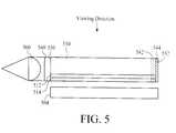
- FIG. 5is a depiction of a flat panel micro-display that includes a reflective LCD panel located below an edge lit flat panel illumination system, with the flat panel illumination system including an integrated collimating lens, an integrated diffuser, and a quarter wave plate and reflector combination in accordance with an embodiment of the invention.
- FIG. 6is a process flow diagram of a method for illuminating a display panel in accordance with an embodiment of the invention.
- FIG. 3is a depiction of a flat panel micro-display system that includes a reflective liquid crystal display (LCD) panel 304 below a flat panel illumination system 306 .
- the flat panel illumination systememits polarized light to the reflective LCD panel in a polarization state that is desired by the reflective LCD panel.
- the flat panel illumination systemincludes a light source 308 , a diffuser 340 , an edge lit flat panel lightguide 310 , a polarizing system 312 that passes one state of polarization while reflecting the other polarization state, a quarter wave plate 314 , a polarization rotator 342 , and a reflector 344 .
- Each of the elements of the flat panel display systemis described below followed by a description of the operation of the flat panel display system and various alternative embodiments. It should be noted that throughout the description, similar reference numerals are utilized to identify similar elements.
- the reflective LCD panel 304includes conventional LCDs as are known in the field. LCDs operate by selectively applying electrical fields to certain picture elements (pixels) in order to turn the polarization of light that is incident on the picture elements. The polarized light is selectively turned at each picture element such that the light will be reflected (in the case of reflective LCDs) or passed (in the case of transmissive LCDs). By controlling the electrical fields applied to a matrix of pixels within a LCD panel, various graphic images can be displayed.
- a ferro-electric liquid crystal (FLC) panelis utilized for the reflective LCD panel.
- FLCferro-electric liquid crystal
- the light source 308 of the flat panel illumination system 306includes one or more light emitting diodes (LEDs) or a fluorescent light source, such as a rod shaped light source, that inject light, typically unpolarized light, into the flat panel lightguide 310 .
- the light sourceis located along an edge face of the flat panel lightguide, the light source may include a light source reflector that maximizes the amount of light that is directed into the edge face of the flat panel lightguide although this is not required. Other light sources may be utilized to illuminate the LCD panel.
- the diffuser 340 of the flat panel illumination system 306diffuses light that enters the flat panel lightguide 310 .
- the diffuseris typically utilized when the light is generated from one or more LEDs. Although the diffuser is shown separate from the lightguide, the diffuser may be integrated into the lightguide.
- the edge lit flat panel lightguide 310 of the flat panel illumination system 306includes a glass or plastic panel having first (top) and second (bottom) major surfaces 346 and 348 and first (left) and second (right) edge face surfaces 350 and 352 .
- the second major surface (bottom) of the lightguideis proximate to the reflective LCD panel 304
- the first edge face (left)is proximate to the light source 308
- the second edge face (right)is on the opposite side of the lightguide from the light source.
- the flat panel lightguideis constructed from a material having isotropic properties although the lightguide may alternatively have anisotropic, or birefringent, properties.
- the polarizing system 312 of the flat panel illumination system 306includes a polarizing layer such as a fine linear grating or a high angle, high efficiency polarizing beam splitter that is formed proximate to the second (bottom) surface 348 of the flat panel lightguide 310 .
- the polarizing systempasses light having a desired polarization state and reflects light having an undesired polarization state.
- An embodiment of the fine linear gratingis formed by molding or etching and an embodiment of the polarizing beam splitter is formed by applying an optical thin film coating or a film layer, such as a commercially available brightness enhancing film (e.g., 3M BEF), to the bottom surface of the flat panel lightguide.
- an optical thin film coating or a film layersuch as a commercially available brightness enhancing film (e.g., 3M BEF)
- the polarizing systemoperates to transmit, or pass, light having the desired polarization state while in other embodiments, the polarization system may operate to reflect light having the desired polarization state.
- the embodiment of FIG. 3has the polarization system on the bottom surface of the flat panel lightguide, the polarization system may alternatively be located opposite to a transmissive LCD panel, with the desired light passing through the polarization system where it is reflected back through the lightguide and to the transmissive LCD panel.
- the quarter wave plate 314 of the flat panel illumination system 306is formed proximate to the polarization system 312 and the bottom surface 348 of the flat panel lightguide.
- the quarter wave platehelps to compensate for the half wave (90 degrees) polarization rotation that is caused by the reflective LCD panel 304 .
- By adding the quarter wave plate between the polarization system and the reflective LCD panellight that passes the polarizing system is rotated twice by the quarter wave plate and once by the reflective LCD panel such that all of the light having the desired polarization state that is passed down through the polarization system passes back up through the system after being reflected by the LCD panel.
- the polarization rotator 342 of the flat panel illumination system 306includes a quarter wave plate.
- the polarization rotatoris formed proximate to the second edge face 352 and perpendicular to the top and bottom major surfaces 346 and 348 of the flat panel lightguide 310 .
- the quarter wave plateis perpendicular to the top and bottom major surfaces of the flat panel lightguide, it should be understood that other orientations that accomplish polarization rotation of the reflected portions of light are possible.
- the quarter wave plateis formed of different layers having different refractive indices. The quarter wave plate is constructed such that light passing through the quarter wave plate is rotated by a quarter wave.
- Light that passes through the quarter wave plate twiceis rotated by a half wave (90 degrees) such that, for example, S polarized light is changed to P polarized light.
- a half wave plateis described, other polarization rotators may be utilized to accomplish the half wave rotation of the polarization state.
- the reflector 344 of the flat panel illumination systemis formed to reflect the portions of light that are initially reflected by the polarization system.
- the reflectoris formed on the second edge face 352 of the flat panel lightguide 310 and is perpendicular to the top and bottom major surfaces 346 and 348 of the flat panel lightguide. Although it is preferred that the reflector is perpendicular to the top and bottom major surfaces, it should be understood that other orientations that accomplish light reflection are possible.
- the reflectoris a polarization maintaining reflector such as a mirror that does not change the polarization state of reflected light.
- a flat panel micro-display systemincludes a LCD panel and a lightguide having dimensions on the order of 5 mm by 4 mm.
- the flat panel micro-display systemtypically includes an optical element such as a magnifier, above the illumination system 306 that magnifies the pixels of the LCD panel 304 so that the intended image can be clearly seen by the human eye from the viewing direction.
- a magnification system with multiple lensesmay be utilized.
- FIG. 4is an example depiction of how light propagates through the system of FIG. 3 .
- light generated at the light source 408enters the flat panel lightguide 410 at the first edge face 450 , with the light containing nearly equal portions of P polarized and S polarized light.
- Light that is incident on the polarization system 412 with an angle 452 that is larger than the Total Internal Reflection (TIR) angle defined by Snell's lawis either passed by the polarization system or reflected depending on the polarization state.
- TIRTotal Internal Reflection
- the P polarized lightpasses through the polarization system and is rotated a quarter wavelength by the quarter wave plate 414 .
- the lightis then reflected by the reflective LCD panel 404 and the polarization state of the reflected light is rotated by half a wave in the process.
- the reflected lighttravels back up through the quarter wave plate where it is rotated again by a quarter wave back to its original P polarization state.
- the P polarized lightpropagates through the polarization system and the flat panel lightguide, as indicated by the dashed line 430 , so that it can be seen from the viewing direction.
- the reflected S polarized lightcontinues to be internally reflected as the S polarized light propagates within the lightguide.
- the S polarized lighteventually passes through the quarter wave plate 442 proximate to the second edge face 452 and is rotated by a quarter wave.
- the rotated lightis then reflected by the reflector 444 and passes again through the quarter wave plate where it is rotated by a quarter wavelength.
- the two rotations and reflectioncause the S polarized light that propagates towards the quarter wave plate/reflector combination to propagate away from the quarter wave plate/reflector combination as P polarized light.
- the P polarized lightthen propagates through the lightguide 450 and eventually contacts the polarization system 412 .
- the P polarized light that is incident on the polarization systemis passed by the polarization system as indicated by the dashed line 456 and is utilized to illuminate the reflective LCD panel 404 .
- the reflector 444is preferably a polarization maintaining reflector so that all of the S polarized light that propagates towards the quarter wave plate/reflector 442 and 444 combination is changed to P polarized light in a controlled manner.
- the quarter wave plate/reflector combinationchanges all, or nearly all, of the S polarized light into P polarized light, which is then utilized to illuminate the LCD panel 404 .
- FIG. 5is a depiction of another embodiment of a flat panel display system that includes the quarter wave plate 542 and reflector 544 combination proximate to the second edge face 552 as described above with reference to FIGS. 3 and 4.
- a collimating lens 560 and diffuser 540are integrated into the flat panel lightguide 510 at or near the first edge face 550 .
- the collimating lens and diffusermay be separate from the lightguide or may be used one without the other.
- a method for illuminating a display panelis depicted in the process flow diagram of FIG. 6 .
- a step 602light is input into a first edge face of a lightguide, with the lightguide having a first major surface opposite a second major surface.
- a step 604a first portion of the light having a desired polarization state is passed through a polarization system that is proximate to the first major surface of the waveguide.
- a second portion of the light having an undesired polarization stateis reflected from the polarization system that is proximate to the first major surface of the waveguide.
- a step 608the second portion of the light is passed through a polarization rotator to rotate the polarization state of the second portion of the light to the desired polarization state from the undesired polarization state.
- the second portion of the lightis reflected at a second edge face that is opposite the first edge face.
- the second portion of the lightis passed through the polarization system after the polarization state of the second portion of light has been rotated to the desired polarization state and after the second portion of the light has been reflected at the second edge face.
Landscapes
- Physics & Mathematics (AREA)
- General Physics & Mathematics (AREA)
- Optics & Photonics (AREA)
- Nonlinear Science (AREA)
- Spectroscopy & Molecular Physics (AREA)
- Engineering & Computer Science (AREA)
- General Engineering & Computer Science (AREA)
- Mathematical Physics (AREA)
- Chemical & Material Sciences (AREA)
- Crystallography & Structural Chemistry (AREA)
- Light Guides In General And Applications Therefor (AREA)
Abstract
Description
Claims (32)
Priority Applications (1)
| Application Number | Priority Date | Filing Date | Title |
|---|---|---|---|
| US09/585,200US6352350B1 (en) | 2000-06-01 | 2000-06-01 | High efficiency flat illuminator for liquid crystal micro-display |
Applications Claiming Priority (1)
| Application Number | Priority Date | Filing Date | Title |
|---|---|---|---|
| US09/585,200US6352350B1 (en) | 2000-06-01 | 2000-06-01 | High efficiency flat illuminator for liquid crystal micro-display |
Publications (1)
| Publication Number | Publication Date |
|---|---|
| US6352350B1true US6352350B1 (en) | 2002-03-05 |
Family
ID=24340431
Family Applications (1)
| Application Number | Title | Priority Date | Filing Date |
|---|---|---|---|
| US09/585,200Expired - LifetimeUS6352350B1 (en) | 2000-06-01 | 2000-06-01 | High efficiency flat illuminator for liquid crystal micro-display |
Country Status (1)
| Country | Link |
|---|---|
| US (1) | US6352350B1 (en) |
Cited By (38)
| Publication number | Priority date | Publication date | Assignee | Title |
|---|---|---|---|---|
| US20020036733A1 (en)* | 2000-08-09 | 2002-03-28 | Jang-Gun Park | Reflection type liquid crystal display |
| US20030030765A1 (en)* | 2001-07-30 | 2003-02-13 | Shunichiro Hayashi | Liquid crystal display apparatus |
| US6598989B2 (en)* | 2001-09-10 | 2003-07-29 | Wintek Corporation | Face light source module structure |
| US6637905B1 (en)* | 2002-09-26 | 2003-10-28 | Agilent Technologies, Inc. | Method and system for providing backlighting utilizing a luminescent impregnated material |
| US6669349B2 (en)* | 2000-09-20 | 2003-12-30 | Sanyo Electric Co., Ltd. | Beam light source having a beam-shaped light guide |
| US6685328B1 (en)* | 2001-08-27 | 2004-02-03 | Plamone, Inc. | Display having planar light guide with integrally formed frame |
| US20050017948A1 (en)* | 2003-07-21 | 2005-01-27 | Motorola, Inc. | Wireless device lighting system |
| US20050231654A1 (en)* | 2002-03-06 | 2005-10-20 | Koninklijke Philips Electronics N.V. | Projection device having an increased efficiency |
| US20050264719A1 (en)* | 2004-05-31 | 2005-12-01 | Kuang-Tao Sung | Display device and electronic device utilizing the same |
| US20060245061A1 (en)* | 2005-04-15 | 2006-11-02 | Jin-Sung Choi | Light guide plate, backlight assembly having the same, display apparatus having the same and method of manufacturing the same |
| US20060279672A1 (en)* | 2005-06-14 | 2006-12-14 | Joong-Hyun Kim | Light guiding plate, backlight assembly having the same, and display device having the same |
| US20070153539A1 (en)* | 2006-01-04 | 2007-07-05 | Nec Lcd Technologies, Ltd. | Light source device and liquid crystal display device using the same |
| US20070170331A1 (en)* | 2006-01-26 | 2007-07-26 | Charles Prater | Mountable cup holder for bottled beverage |
| US20070289953A1 (en)* | 2001-03-01 | 2007-12-20 | Konica Corporation | Optical element producing method, base material drawing method and base material drawing apparatus |
| US20080129647A1 (en)* | 2000-11-30 | 2008-06-05 | Palm, Inc. | Multi-sided display for portable computer |
| US20080158906A1 (en)* | 2006-11-09 | 2008-07-03 | So Yeon Park | Back light unit |
| CN100419520C (en)* | 2005-03-23 | 2008-09-17 | 李卫民 | a display |
| US20090168393A1 (en)* | 2007-12-31 | 2009-07-02 | Industrial Technology Research Institute | Polarized light illumination device |
| US7852430B1 (en) | 2001-11-29 | 2010-12-14 | Palm, Inc. | Light guide spacers for backlighting a reflective display |
| US7859518B1 (en) | 2001-06-04 | 2010-12-28 | Palm, Inc. | Interface for interaction with display visible from both sides |
| US20110175510A1 (en)* | 2010-02-01 | 2011-07-21 | Benaissance Lighting, Inc. | Tubular lighting products using solid state source and semiconductor nanophosphor, e.g. for florescent tube replacement |
| US20110234943A1 (en)* | 2010-03-23 | 2011-09-29 | Doo-Won Lee | Dual liquid crystal display |
| US20110234525A1 (en)* | 2001-01-30 | 2011-09-29 | Gettemy Shawn R | Single piece top surface display layer and integrated front cover for an electronic device |
| US8134534B1 (en) | 2001-05-22 | 2012-03-13 | Hewlett-Packard Development Company, L.P. | High transparency integrated enclosure touch screen assembly for a portable hand held device |
| JP2012530949A (en)* | 2009-06-23 | 2012-12-06 | シーリアル テクノロジーズ ソシエテ アノニム | Lighting unit for direct-view display |
| US8384674B1 (en) | 2001-01-30 | 2013-02-26 | Hewlett-Packard Development Company, L.P. | Integrated enclosure/touch screen assembly |
| US20130163222A1 (en)* | 2011-12-26 | 2013-06-27 | Wintek Corporation | Illumination module |
| US8891918B2 (en) | 2011-11-17 | 2014-11-18 | At&T Intellectual Property I, L.P. | Methods, systems, and products for image displays |
| WO2015010418A1 (en)* | 2013-07-26 | 2015-01-29 | 京东方科技集团股份有限公司 | Backlight module and display device |
| US8994269B2 (en) | 2010-02-01 | 2015-03-31 | Abl Ip Holding Llc | Lamp using solid state source |
| US20150346525A1 (en)* | 2014-05-29 | 2015-12-03 | Robo-team Ltd. | Liquid crystal display backlight |
| USD751648S1 (en) | 2013-08-21 | 2016-03-15 | Cooper Technologies Company | Light-emitting diode edge lighted airfield guidance sign |
| CN105785499A (en)* | 2016-05-18 | 2016-07-20 | 京东方科技集团股份有限公司 | Side-entrance type light guide plate assembly, side-entrance type backlight module and display device |
| CN105974514A (en)* | 2016-07-22 | 2016-09-28 | 京东方科技集团股份有限公司 | Light guide plate, backlight module and display device |
| US9495892B2 (en) | 2013-08-21 | 2016-11-15 | Cooper Technologies Company | Light-emitting diode edge lighted airfield guidance sign |
| US20170045673A1 (en)* | 2015-08-11 | 2017-02-16 | Samsung Electronics Co., Ltd. | Backlight unit and display apparatus |
| US9684163B2 (en) | 2010-12-03 | 2017-06-20 | E Ink Corporation | Methods, systems, and products for illuminating displays |
| US10054734B2 (en) | 2015-05-08 | 2018-08-21 | Apple Inc. | Liquid crystal display with backlight |
Citations (9)
| Publication number | Priority date | Publication date | Assignee | Title |
|---|---|---|---|---|
| US5099343A (en)* | 1989-05-25 | 1992-03-24 | Hughes Aircraft Company | Edge-illuminated liquid crystal display devices |
| US5587816A (en)* | 1992-10-09 | 1996-12-24 | Asahi Glass Company Ltd. | LCD device including an illumination device having a polarized light separating sheet between a light guide and the display |
| US5729311A (en) | 1995-08-23 | 1998-03-17 | U.S. Philips Corporation | Illumination system for a flat-panel picture display device |
| US5808709A (en)* | 1995-10-24 | 1998-09-15 | Sharp Kabushiki Kaisha | Illuminator with polarization separating anisotropic layer between light guide and reflector |
| US5808713A (en) | 1995-09-22 | 1998-09-15 | U.S. Philips Corporation | Flat-panel picture display device |
| US6005720A (en) | 1998-12-22 | 1999-12-21 | Virtual Vision, Inc. | Reflective micro-display system |
| US6048071A (en)* | 1997-03-28 | 2000-04-11 | Sharp Kabushiki Kaisha | Front illumination device and reflection-type liquid crystal display device incorporating same |
| US6108059A (en)* | 1998-03-10 | 2000-08-22 | Sony Corporation | Reflective display having a laminated structure of a polarizer and quarter wave plate being attached to a light guide plate |
| US6239851B1 (en)* | 1995-10-12 | 2001-05-29 | Ibm Corporation | Planar light source device having polarization separator formed of two sheets with mating triangular prisms and different indices of refraction |
- 2000
- 2000-06-01USUS09/585,200patent/US6352350B1/ennot_activeExpired - Lifetime
Patent Citations (9)
| Publication number | Priority date | Publication date | Assignee | Title |
|---|---|---|---|---|
| US5099343A (en)* | 1989-05-25 | 1992-03-24 | Hughes Aircraft Company | Edge-illuminated liquid crystal display devices |
| US5587816A (en)* | 1992-10-09 | 1996-12-24 | Asahi Glass Company Ltd. | LCD device including an illumination device having a polarized light separating sheet between a light guide and the display |
| US5729311A (en) | 1995-08-23 | 1998-03-17 | U.S. Philips Corporation | Illumination system for a flat-panel picture display device |
| US5808713A (en) | 1995-09-22 | 1998-09-15 | U.S. Philips Corporation | Flat-panel picture display device |
| US6239851B1 (en)* | 1995-10-12 | 2001-05-29 | Ibm Corporation | Planar light source device having polarization separator formed of two sheets with mating triangular prisms and different indices of refraction |
| US5808709A (en)* | 1995-10-24 | 1998-09-15 | Sharp Kabushiki Kaisha | Illuminator with polarization separating anisotropic layer between light guide and reflector |
| US6048071A (en)* | 1997-03-28 | 2000-04-11 | Sharp Kabushiki Kaisha | Front illumination device and reflection-type liquid crystal display device incorporating same |
| US6108059A (en)* | 1998-03-10 | 2000-08-22 | Sony Corporation | Reflective display having a laminated structure of a polarizer and quarter wave plate being attached to a light guide plate |
| US6005720A (en) | 1998-12-22 | 1999-12-21 | Virtual Vision, Inc. | Reflective micro-display system |
Cited By (61)
| Publication number | Priority date | Publication date | Assignee | Title |
|---|---|---|---|---|
| US20020036733A1 (en)* | 2000-08-09 | 2002-03-28 | Jang-Gun Park | Reflection type liquid crystal display |
| US6669349B2 (en)* | 2000-09-20 | 2003-12-30 | Sanyo Electric Co., Ltd. | Beam light source having a beam-shaped light guide |
| US9489018B2 (en) | 2000-11-30 | 2016-11-08 | Qualcomm Incorporated | Input detection system for a portable electronic device |
| US20100045633A1 (en)* | 2000-11-30 | 2010-02-25 | Palm, Inc. | Input detection system for a portable electronic device |
| US20080129647A1 (en)* | 2000-11-30 | 2008-06-05 | Palm, Inc. | Multi-sided display for portable computer |
| US20100045628A1 (en)* | 2000-11-30 | 2010-02-25 | Palm, Inc. | Input detection system for a portable electronic device |
| US20110234525A1 (en)* | 2001-01-30 | 2011-09-29 | Gettemy Shawn R | Single piece top surface display layer and integrated front cover for an electronic device |
| US8384674B1 (en) | 2001-01-30 | 2013-02-26 | Hewlett-Packard Development Company, L.P. | Integrated enclosure/touch screen assembly |
| US20070289953A1 (en)* | 2001-03-01 | 2007-12-20 | Konica Corporation | Optical element producing method, base material drawing method and base material drawing apparatus |
| US8134534B1 (en) | 2001-05-22 | 2012-03-13 | Hewlett-Packard Development Company, L.P. | High transparency integrated enclosure touch screen assembly for a portable hand held device |
| US7859518B1 (en) | 2001-06-04 | 2010-12-28 | Palm, Inc. | Interface for interaction with display visible from both sides |
| US6806920B2 (en)* | 2001-07-30 | 2004-10-19 | Kabushiki Kaisha Toshiba | Liquid crystal display apparatus |
| US20030030765A1 (en)* | 2001-07-30 | 2003-02-13 | Shunichiro Hayashi | Liquid crystal display apparatus |
| US6685328B1 (en)* | 2001-08-27 | 2004-02-03 | Plamone, Inc. | Display having planar light guide with integrally formed frame |
| US6598989B2 (en)* | 2001-09-10 | 2003-07-29 | Wintek Corporation | Face light source module structure |
| US7852430B1 (en) | 2001-11-29 | 2010-12-14 | Palm, Inc. | Light guide spacers for backlighting a reflective display |
| US20050231654A1 (en)* | 2002-03-06 | 2005-10-20 | Koninklijke Philips Electronics N.V. | Projection device having an increased efficiency |
| US6637905B1 (en)* | 2002-09-26 | 2003-10-28 | Agilent Technologies, Inc. | Method and system for providing backlighting utilizing a luminescent impregnated material |
| US20050017948A1 (en)* | 2003-07-21 | 2005-01-27 | Motorola, Inc. | Wireless device lighting system |
| US7193620B2 (en) | 2003-07-21 | 2007-03-20 | Motorola, Inc. | Wireless device lighting system |
| US20050264719A1 (en)* | 2004-05-31 | 2005-12-01 | Kuang-Tao Sung | Display device and electronic device utilizing the same |
| CN100419520C (en)* | 2005-03-23 | 2008-09-17 | 李卫民 | a display |
| US20060245061A1 (en)* | 2005-04-15 | 2006-11-02 | Jin-Sung Choi | Light guide plate, backlight assembly having the same, display apparatus having the same and method of manufacturing the same |
| US7517129B2 (en)* | 2005-04-15 | 2009-04-14 | Samsung Electronics Co., Ltd. | Light guide plate, backlight assembly having the same, display apparatus having the same and method of manufacturing the same |
| US20060279672A1 (en)* | 2005-06-14 | 2006-12-14 | Joong-Hyun Kim | Light guiding plate, backlight assembly having the same, and display device having the same |
| US7847880B2 (en) | 2005-06-14 | 2010-12-07 | Samsung Electronics Co., Ltd. | Light guiding plate with refractive member, backlight assembly having the same, and display device having the same |
| US7585098B2 (en)* | 2006-01-04 | 2009-09-08 | Nec Lcd Technologies, Ltd. | Light source device and liquid crystal display device using the same |
| US20070153539A1 (en)* | 2006-01-04 | 2007-07-05 | Nec Lcd Technologies, Ltd. | Light source device and liquid crystal display device using the same |
| US20070170331A1 (en)* | 2006-01-26 | 2007-07-26 | Charles Prater | Mountable cup holder for bottled beverage |
| US20080158906A1 (en)* | 2006-11-09 | 2008-07-03 | So Yeon Park | Back light unit |
| US7703972B2 (en)* | 2006-11-09 | 2010-04-27 | Lg Electronics Inc. | Back light unit |
| US7896510B2 (en)* | 2007-12-31 | 2011-03-01 | Industrial Technology Research Institute | Polarized light illumination device |
| US20090168393A1 (en)* | 2007-12-31 | 2009-07-02 | Industrial Technology Research Institute | Polarized light illumination device |
| KR101942210B1 (en) | 2009-06-23 | 2019-01-24 | 시리얼 테크놀로지즈 에스.에이. | Lighting device for a direct viewing display |
| JP2012530949A (en)* | 2009-06-23 | 2012-12-06 | シーリアル テクノロジーズ ソシエテ アノニム | Lighting unit for direct-view display |
| KR20170104626A (en)* | 2009-06-23 | 2017-09-15 | 시리얼 테크놀로지즈 에스.에이. | Lighting device for a direct viewing display |
| US20110175510A1 (en)* | 2010-02-01 | 2011-07-21 | Benaissance Lighting, Inc. | Tubular lighting products using solid state source and semiconductor nanophosphor, e.g. for florescent tube replacement |
| US8994269B2 (en) | 2010-02-01 | 2015-03-31 | Abl Ip Holding Llc | Lamp using solid state source |
| US9277607B2 (en) | 2010-02-01 | 2016-03-01 | Abl Ip Holding Llc | Lamp using solid state source |
| US9719012B2 (en)* | 2010-02-01 | 2017-08-01 | Abl Ip Holding Llc | Tubular lighting products using solid state source and semiconductor nanophosphor, E.G. for florescent tube replacement |
| US20110234943A1 (en)* | 2010-03-23 | 2011-09-29 | Doo-Won Lee | Dual liquid crystal display |
| US8638409B2 (en)* | 2010-03-23 | 2014-01-28 | Samsung Display Co., Ltd. | Dual liquid crystal display |
| US9684163B2 (en) | 2010-12-03 | 2017-06-20 | E Ink Corporation | Methods, systems, and products for illuminating displays |
| US8891918B2 (en) | 2011-11-17 | 2014-11-18 | At&T Intellectual Property I, L.P. | Methods, systems, and products for image displays |
| US11041986B2 (en) | 2011-11-17 | 2021-06-22 | At&T Intellectual Property I, L.P. | Methods, systems, and products for image displays |
| US10591661B2 (en) | 2011-11-17 | 2020-03-17 | At&T Intellectual Property I, L.P. | Methods, systems, and products for image displays |
| US9377574B2 (en) | 2011-11-17 | 2016-06-28 | At&T Intellectual Property I, L.P. | Methods, systems, and products for image displays |
| US9891370B2 (en) | 2011-11-17 | 2018-02-13 | At&T Intellectual Property I, L.P. | Methods, systems, and products for image displays |
| US20130163222A1 (en)* | 2011-12-26 | 2013-06-27 | Wintek Corporation | Illumination module |
| US9618684B2 (en) | 2013-07-26 | 2017-04-11 | Boe Technology Group Co., Ltd. | Backlight module and display device |
| WO2015010418A1 (en)* | 2013-07-26 | 2015-01-29 | 京东方科技集团股份有限公司 | Backlight module and display device |
| US9495892B2 (en) | 2013-08-21 | 2016-11-15 | Cooper Technologies Company | Light-emitting diode edge lighted airfield guidance sign |
| USD751648S1 (en) | 2013-08-21 | 2016-03-15 | Cooper Technologies Company | Light-emitting diode edge lighted airfield guidance sign |
| US9709847B2 (en)* | 2014-05-29 | 2017-07-18 | Robo-Team Defense Ltd. | Liquid crystal display backlight |
| US20150346525A1 (en)* | 2014-05-29 | 2015-12-03 | Robo-team Ltd. | Liquid crystal display backlight |
| US10054734B2 (en) | 2015-05-08 | 2018-08-21 | Apple Inc. | Liquid crystal display with backlight |
| US20170045673A1 (en)* | 2015-08-11 | 2017-02-16 | Samsung Electronics Co., Ltd. | Backlight unit and display apparatus |
| CN105785499A (en)* | 2016-05-18 | 2016-07-20 | 京东方科技集团股份有限公司 | Side-entrance type light guide plate assembly, side-entrance type backlight module and display device |
| CN105785499B (en)* | 2016-05-18 | 2018-11-13 | 京东方科技集团股份有限公司 | Edge-type light guide plate component, side entrance back module and display device |
| CN105974514A (en)* | 2016-07-22 | 2016-09-28 | 京东方科技集团股份有限公司 | Light guide plate, backlight module and display device |
| CN105974514B (en)* | 2016-07-22 | 2018-12-11 | 京东方科技集团股份有限公司 | Light guide plate, backlight module and display device |
Similar Documents
| Publication | Publication Date | Title |
|---|---|---|
| US6352350B1 (en) | High efficiency flat illuminator for liquid crystal micro-display | |
| US6515785B1 (en) | Optical devices using reflecting polarizing materials | |
| US5845035A (en) | Illumination system for a flat-panel picture display device | |
| US6163351A (en) | Backlight for liquid crystal display apparatus and liquid crystal display apparatus incorporating the same | |
| US6975455B1 (en) | Transflective layer for displays | |
| TW571159B (en) | Polarized display with wide-angle illumination | |
| US7315671B2 (en) | Display illumination system and manufacturing method thereof | |
| KR970707460A (en) | An illumination system for a flat panel image display device (a flat-panel picture display device) | |
| JP2001507483A (en) | Display device | |
| JP4794069B2 (en) | Illumination device and liquid crystal display device | |
| KR20010104725A (en) | Display device | |
| KR970707463A (en) | Flat-panel picture display device | |
| US6741304B2 (en) | Display device | |
| TW201026997A (en) | Optical sheet, illuminating device and liquid crystal display device | |
| US20060250541A1 (en) | Illumination system | |
| JPH10161123A (en) | Lighting device and display device | |
| JP3604413B2 (en) | Direct-view liquid crystal display | |
| Jagt et al. | 45.3: Micro‐structured Polymeric Linearly Polarized Light Emitting Lightguide for LCD Illumination | |
| KR101331814B1 (en) | Polariation sheet and lliquid crystal display device having therof | |
| KR100329325B1 (en) | Liquid crystal display | |
| US6795244B2 (en) | Illumination arrangement | |
| US6886954B2 (en) | System and method for processing light in an electronic display system | |
| KR101281668B1 (en) | Reflective polarizing plate and liquid crystal display device having thereof | |
| JP2002221705A (en) | Liquid crystal display with touch panel |
Legal Events
| Date | Code | Title | Description |
|---|---|---|---|
| AS | Assignment | Owner name:AGILENT TECHNOLOGIES, CALIFORNIA Free format text:ASSIGNMENT OF ASSIGNORS INTEREST;ASSIGNOR:MA, GUOLIN;REEL/FRAME:010866/0574 Effective date:20000601 | |
| STCF | Information on status: patent grant | Free format text:PATENTED CASE | |
| FPAY | Fee payment | Year of fee payment:4 | |
| AS | Assignment | Owner name:AVAGO TECHNOLOGIES GENERAL IP PTE. LTD., SINGAPORE Free format text:ASSIGNMENT OF ASSIGNORS INTEREST;ASSIGNOR:AGILENT TECHNOLOGIES, INC.;REEL/FRAME:017207/0020 Effective date:20051201 | |
| AS | Assignment | Owner name:CITICORP NORTH AMERICA, INC.,DELAWARE Free format text:SECURITY AGREEMENT;ASSIGNOR:AVAGO TECHNOLOGIES GENERAL IP (SINGAPORE) PTE. LTD.;REEL/FRAME:017207/0882 Effective date:20051201 Owner name:CITICORP NORTH AMERICA, INC., DELAWARE Free format text:SECURITY AGREEMENT;ASSIGNOR:AVAGO TECHNOLOGIES GENERAL IP (SINGAPORE) PTE. LTD.;REEL/FRAME:017207/0882 Effective date:20051201 | |
| AS | Assignment | Owner name:AVAGO TECHNOLOGIES ECBU IP (SINGAPORE) PTE. LTD., SINGAPORE Free format text:ASSIGNMENT OF ASSIGNORS INTEREST;ASSIGNOR:AVAGO TECHNOLOGIES GENERAL IP (SINGAPORE) PTE. LTD.;REEL/FRAME:017675/0518 Effective date:20060127 Owner name:AVAGO TECHNOLOGIES ECBU IP (SINGAPORE) PTE. LTD.,S Free format text:ASSIGNMENT OF ASSIGNORS INTEREST;ASSIGNOR:AVAGO TECHNOLOGIES GENERAL IP (SINGAPORE) PTE. LTD.;REEL/FRAME:017675/0518 Effective date:20060127 Owner name:AVAGO TECHNOLOGIES ECBU IP (SINGAPORE) PTE. LTD., Free format text:ASSIGNMENT OF ASSIGNORS INTEREST;ASSIGNOR:AVAGO TECHNOLOGIES GENERAL IP (SINGAPORE) PTE. LTD.;REEL/FRAME:017675/0518 Effective date:20060127 | |
| FPAY | Fee payment | Year of fee payment:8 | |
| AS | Assignment | Owner name:TAIWAN SEMICONDUCTOR MANUFACTURING COMPANY, LTD., Free format text:ASSIGNMENT OF ASSIGNORS INTEREST;ASSIGNORS:AVAGO TECHNOLOGIES GENERAL IP (SINGAPORE) PTE. LTD.;AVAGO TECHNOLOGIES ECBU IP (SINGAPORE) PTE. LTD.;REEL/FRAME:026875/0665 Effective date:20101223 | |
| FPAY | Fee payment | Year of fee payment:12 | |
| AS | Assignment | Owner name:AVAGO TECHNOLOGIES GENERAL IP (SINGAPORE) PTE. LTD Free format text:CORRECTIVE ASSIGNMENT TO CORRECT THE NAME OF THE ASSIGNEE PREVIOUSLY RECORDED ON REEL 017207 FRAME 0020. ASSIGNOR(S) HEREBY CONFIRMS THE ASSIGNMENT;ASSIGNOR:AGILENT TECHNOLOGIES, INC.;REEL/FRAME:038633/0001 Effective date:20051201 |