US6352349B1 - Illumination system for use in imaging moving articles - Google Patents
Illumination system for use in imaging moving articlesDownload PDFInfo
- Publication number
- US6352349B1 US6352349B1US09/535,051US53505100AUS6352349B1US 6352349 B1US6352349 B1US 6352349B1US 53505100 AUS53505100 AUS 53505100AUS 6352349 B1US6352349 B1US 6352349B1
- Authority
- US
- United States
- Prior art keywords
- light
- conveyor
- light source
- fresnel lens
- camera
- Prior art date
- Legal status (The legal status is an assumption and is not a legal conclusion. Google has not performed a legal analysis and makes no representation as to the accuracy of the status listed.)
- Expired - Lifetime
Links
Images


Classifications
- G—PHYSICS
- G06—COMPUTING OR CALCULATING; COUNTING
- G06K—GRAPHICAL DATA READING; PRESENTATION OF DATA; RECORD CARRIERS; HANDLING RECORD CARRIERS
- G06K7/00—Methods or arrangements for sensing record carriers, e.g. for reading patterns
- G06K7/10—Methods or arrangements for sensing record carriers, e.g. for reading patterns by electromagnetic radiation, e.g. optical sensing; by corpuscular radiation
- G06K7/10544—Methods or arrangements for sensing record carriers, e.g. for reading patterns by electromagnetic radiation, e.g. optical sensing; by corpuscular radiation by scanning of the records by radiation in the optical part of the electromagnetic spectrum
- G06K7/10712—Fixed beam scanning
- G06K7/10722—Photodetector array or CCD scanning
- G06K7/10732—Light sources
Definitions
- the present inventionrelates to camera lighting systems, and more particularly relates to an apparatus and method for illuminating articles moving beneath a camera on a conveyor belt.
- An overhead linear CCD (Charge Coupled Device) cameracan capture narrow images of a field of view across a “scan line” that is very short in the direction of conveyor travel, but extends across the conveyor.
- a computer receiving the output of the cameracan build from these linear images a full digital image of a parcel or a label passing under the camera.
- the cameracan take an image anywhere in a “scan plane” projected downward from the camera to the scan line.
- Prior illumination systemshave produced an intensive strip of light along the scan line by using elliptical cylinders as reflectors behind an elongated tubular lamp.
- the lamplies along one focal axis of the ellipse, while the surface to be illuminated lies near the other focal axis.
- the light sourcemay be inclined about the axis of the scan line so as not to obstruct the camera's field of view.
- the region of focused bright illuminationis not vertically deep within the scan plane, and thus the efficacy of this configuration is limited when the articles passing beneath the camera vary widely in height.
- Such an illumination systemseeks to direct enough light reflected from the subject article to the camera to obtain a sharp image, without blinding the camera with glare.
- the light sourcesshould provide a large amount of diffuse reflection to the camera, but no specular reflection.
- articles with shiny upper surfacespresent a particular challenge. If the angle of inclination of the light source about the scan line is small, the camera may be blinded by glare reflected from glossy packages or from plastic protectors used to protect paper labels. If the angle of inclination is large, tall articles may cast shadows onto leading or trailing articles when they are under the camera.
- the light sourcecan cover only a relatively small depth vertically in the scan plane, because elliptical reflectors cast a narrow beam transverse to the length of the reflector.
- One prior systemprovides an unsymmetrical elliptical reflector to illuminate a vertical region in the scan plane, but this approach does not solve all the problems noted above.
- Patents disclosing illumination systemsinclude U.S. Pat. Nos.:
- an illumination systemcapable of providing adequate diffuse light to an overhead camera, reflected from a vertical region sufficient to accommodate a range of article heights.
- the illumination systemshould avoid reflecting glare to the camera, and should direct light so that tall articles do not cast shadows into the illuminated region.
- the present inventionseeks to provide a system and method for illuminating a surface of an article being imaged by a camera so as to reflect diffuse light to the camera from articles of varying heights.
- this objectis accomplished in an illumination system by providing an apparatus for illuminating a surface of an article being imaged by a camera, comprising an elongated light source angled with respect to the surface of the article and positioned alongside the article to direct light toward the surface; and a light directing device positioned to receive light from the light source and to direct the light toward the surface at an angle equal to or greater than forty degrees from an optical axis of the camera.
- the light sourceis positioned alongside the conveyor to direct light angled downwardly and from the side of the conveyor.
- the light directed by the light directing deviceforms an illuminated strip on an upper surface of the articles transverse to their direction of travel.
- the light sourceis an elongated lamp and an elongated reflector positioned to reflect light from the lamp toward the articles
- the light directing deviceis a Fresnel lens.
- the Fresnel lenshas an optical axis that is offset from an axis of symmetry of the light source.
- the Fresnel lensbends light from the light source to a larger angle with respect to the optical axis of the camera.
- the optical axis of the lensis offset from the axis of symmetry of the light source away from the article along the direction of the optical axis of the camera to more efficiently illuminate both short and tall articles.
- a barriersuch as a housing surrounding the light directing device, may be used to block light from the light source except light passing through the light directing device.
- the inventionalso provides an automatic conveyor system in which the longitudinal axis of the lamp is approximately perpendicular to the path of travel of articles along the conveyor.
- the reflectorpreferably is an elliptical surface and the lamp lies along a first focal axis of the elongated reflector.
- the second focal axis of the reflectorpreferably lies a distance beneath the conveyor.
- the Fresnel lensis positioned a distance from the lamp from about 1 ⁇ 4 to about 1 ⁇ 2 times the focal length of the Fresnel lens and a distance from a central axis of the conveyor approximately equal to 1 to 2 times the focal length of the Fresnel lens, and the optical axis of the Fresnel lens is offset from the axis of symmetry of the reflector by a distance from about 0.5 to 1 times the length of the lamp filament.
- the illumination systemincludes a plurality of illumination assemblies, including light sources and light directing devices, positioned to provide light to the illuminated region of the camera's scan plane.
- a plurality of illumination assembliesincluding light sources and light directing devices, positioned to provide light to the illuminated region of the camera's scan plane.
- four such assembliesare provided, the first and second assemblies on one side of the conveyor, one above the other, and the third and fourth assemblies on the opposite side of the conveyor, one above the other.
- the first and second assemblieson one side of the conveyor, one above the other, and the third and fourth assemblies on the opposite side of the conveyor, one above the other.
- their symmetry planesubstantially coincides with the camera's scan plane.
- theymay be aligned with the camera's scan plane to maximize illumination.
- theymay be positioned with their symmetry planes slightly mis-aligned to create a thickness in the illuminated region spanning the scan plane, and thus in the illuminated strip on the surface of the article.
- the lamps, reflectors, lenses, and barriersare selected, assembled and oriented such that the articles are illuminated from the side of the conveyor, such that essentially all of the light exiting the lens is aligned at an angle equal to or greater than forty-five degrees from the optical axis of the camera, and such that diffuse reflection but essentially no specular reflection from the articles reaches the camera. Because the light sources are to the side of the conveyor, tall articles cannot cast shadows on leading or trailing articles. The preferred arrangement of multiple light sources illuminates a deep region of the scan plane without the need to position any light source so high as to create glare into the camera.
- the present inventionalso provides a method for illuminating articles moving on a conveyor in a direction of travel under a camera, comprising the steps of directing a beam of light from the side of the conveyor at a downward angle toward the articles; and collimating the beam to direct the light at an angle equal to or greater than forty degrees from an optical axis of the camera and to form an illuminated strip on an upper surface of the articles transverse to the direction of travel.
- a pair of additional illumination assembliesmay be installed within the footprint of the camera's field of view, if necessary for tall articles.
- the reflector of the light sourcemay be part of a cone-shaped figure, rather than part of a cylinder. As a result, the lamp is inclined with respect to the second focal axis of the reflector. This configuration allows the light to be focused parallel to the scan line despite the inclination of the lamp.
- the light directing devicecan be a set of multiple apertures forming narrow slots across the reflector, under the lamp and perpendicular to the filament axis. Reflective and diffusing surfaces within the slots are configured to avert direct illumination of the articles by beams having an angle of incidence less than forty degrees from the camera's optical axis, and to create useful diffuse light from undesirable direct light beams.
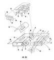
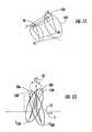
- FIG. 1is a perspective view of a conveyor system including an illumination apparatus embodying the present invention.
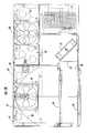
- FIG. 2Ais an exploded pictorial view of an illumination assembly including cooling systems for the lens and for the lamp
- FIG. 2Bis a cross sectional view taken along line 2 B— 2 B of FIG. 2 A.
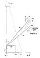
- FIG. 3is a diagrammatic exploded view of the components of the illumination assembly and their relation to the camera.
- FIG. 4is diagrammatic top view of the light source and its relation to an article being imaged.
- FIG. 7is a diagrammatic, enlarged, partial side view of an illumination assembly showing the refractive function of the Fresnel lens.
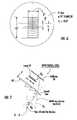
- FIG. 8is a diagrammatic front view of another embodiment of the invention incorporating an alternative light directing device.
- FIG. 10is a diagrammatic view of an alternative reflector for use with vertical lamp filaments.
- FIG. 11is a diagrammatic view of an alternative cone-shaped reflector configured to compensate for a tilted lamp.
- FIG. 13is a side view of the embodiment of FIG. 12 .
- FIG. 1shows a conveyor system 10 including an illumination apparatus 11 embodying the present invention.
- the conveyor system 10includes a conveyor belt 12 that travels in the direction of the arrow T on a conveyor bed 14 , and an imaging station 15 that includes the illumination apparatus 11 .
- a superstructure 17straddles the conveyor belt 12 and supports a camera 18 having an optical axis D-D directed vertically down to the conveyor belt.
- the camera 18preferably is a linear CCD camera.
- the field of view of the camerahas a width encompassing the width of the conveyor belt 12 , and a length or thickness in the direction of travel T, for example 0.00535 inch (0.013589 cm).
- the camerascans a narrow strip (scan line SL) across the width of the conveyor belt 12 or across the upper surface of an article moving with the conveyor belt.
- Such a camera systemis described in U.S. Pat. No. 5,308,960.
- the camerapreferably has a long depth of focus or an automatic focusing apparatus, such as described in U.S. Pat. No. 5,245,172 or U.S. Pat. No. 5,485,263. As shown in FIG.
- the camera 18acquires linear images of small strips within its field of view and assembles them in a computer memory to form a two-dimensional digital image of the top of the parcel 100 including the label 110 .
- Computer softwarealso known in the art then analyzes the image to locate and decode symbols and text in the image to assist in recognition and sorting of the parcel 100 .
- the conveyor system 10can also be used for processing components of manufactured goods or other articles carrying identifying indicia or having a shape discernable in an image.
- the optical axisis approximately centered on the width of the chamber 30 , but offset from the center along the length of the chamber a distance b from about 0.5 to 1 times the length of the lamp 40 .
- the lamp 40is about 5 inches (about 12.7 cm) long and the optical axis of the lens 45 is offset about 4 inches (about 10.2 cm).
- the depth of the lens chamber 30is selected so that the distance r from the lamp 40 to the lens 45 is between about one-quarter and one-half the focal length of the lens 45 .
- the focal length fis 30 inches (76 cm)
- the distance rpreferably is about 8 inches (about 20 cm).
- the refraction of the light from the lamp 40 by a portion of the Fresnel lens 45is shown diagrammatically in FIG. 7 .
- An example ray R S emanating from the lampis shown reflecting from the reflector 38 along a path (shown in dashed line) that would reflect specularly from an article on the conveyor to the camera 18 .
- the triangular rib of the Fresnel lens 45bends the ray to a path R D that makes an angle ⁇ of at least 40 degrees with the optical axis D-D of the camera 18 .
- the rays R D projected by the lens 45 toward the article on the conveyorwill create diffuse reflection to the camera, not glare.
- light passing directly from the lamp to the lensis refracted similarly.
- FIGS. 3 and 4The preferred configuration of the light source and light directing device with respect to the conveyor 12 is shown diagrammatically in FIGS. 3 and 4.
- a parcel 100is shown on the conveyor 12 .
- the axis of symmetry C-D of the reflector 38makes an angle of about 45 degrees with the optical axis D-D of the camera 18 .
- the lamp 40lies along the first focal axis A-A of the reflector 38 .
- the Fresnel lens 45is spaced a distance r in front of the lamp, with its optical axis F-F parallel to but offset from the axis C-D by a distance b in a direction (along the camera axis D-D) away from the parcel 100 .
- the lens 45is positioned a distance s away from the scan line SL on the conveyor belt 12 , the distance s being between about the focal length f and twice the focal length f.
- the second focal axis B-B of the elliptical reflector 38preferably falls slightly below the conveyor belt, as shown in phantom in FIG. 4 .
- FIG. 5shows, diagrammatically in cross section at the scan line SL, the preferred configuration of the illumination apparatus 11 , looking back along the path of travel of the conveyor belt 12 .
- the arrows Rindicate the path of rays of light from the lamps 40 and the reflectors 38 of the lighting modules 20 c and 20 d on one side of the conveyor, the other side of the conveyor being substantially a mirror image.
- all the illuminating raysmake an angle ⁇ of 40 degrees or more, and preferably 45 degrees or more, with the optical axis D-D of the camera 18 .
- This configurationprovides adequate diffuse illumination to the camera for a sharp image, while avoiding specular reflection.
- a recirculating air systemcools the lens 45 .
- Another fan 51is mounted in the heat exchange chamber 32 adjacent to an inlet opening 52 connecting the chamber 32 to the lens chamber 30 .
- the fan 51is mounted at an angle to direct air downwardly onto the lens 45 .
- the airsweeps around the chamber 30 , cooling the lens 45 , and is exhausted by a similarly tilted fan 54 through an outlet opening 55 at the opposite end of the chamber 30 .
- a plurality of heat exchange tubes 57extend across the chamber 32 at its end opposite the lens chamber 30 .
- the tubes 57made of a high heat conductivity material such as copper, are open to the outside air at one end of the chamber 32 , and terminate at a thin plenum 59 at the other end of the chamber.
- a fan 60pressurizes the plenum 59 to force cooling air through the tubes 57 .
- the air exhausted from the lens chamber 30 by the fan 54sweeps around the chamber 32 and over the heat exchange tubes 57 , transferring heat to the cooler air flowing within the tubes.
- the fan 51then forces the cooler air back across the lens 45 .
- appropriate bafflescan be positioned in the lens and heat exchange chambers to direct the flow of recirculating air.
- the recirculating air cooling systems with heat exchangersare enclosed to prevent dust from contacting the optics.
- the illumination apparatus 11projects light from the sides of the conveyor belt 12 as a parcel 100 or other article travels under the imaging station 15 .
- the lamp 40 , reflector 38 , and lens 45configured within the limits described above, light shining on the parcel is angled at 40 degrees or more from the camera's optical axis.
- the projected lightilluminates a region across the conveyor including the scan line SL of the camera 18 and extending above the conveyor as high as the highest expected parcel.
- diffuse light reflected from the parcel, and particularly from a label 110 bearing optically encoded symbols and sometimes machine-readable textreaches the camera 18 . Specular reflection is directed away from the camera, avoiding glare.
- FIG. 8shows a second embodiment of an illumination apparatus 211 according to the present invention, incorporating an alternative light directing device.
- Two different height parcels 100are shown on the conveyor belt 12 . They are illuminated by two lighting modules 220 a and 220 b, which are similar to the modules 20 of the first embodiment, except that the Fresnel lens is replaced by a set of baffle plates 245 , shown in detail in FIG. 9.
- a plurality of parallel baffle plates 248are positioned perpendicular to the lamp 40 and parallel to the axis of symmetry of the reflector 38 .
- each modulehas twelve baffle plates extending about 8 inches (20 cm) parallel to the axis of symmetry of the reflector, and positioned about 0.75 inch (1.9 cm) apart, to form a series of slots for receiving light directly from the lamp and also reflected from the reflector.
- the plate surface on one side of each slotis a completely specular or mirror-like surface 252 .
- the fully specular surface 252 of each plate 248faces slanted upwardly with respect to the camera's optical axis D-D, as a result of the tilting of the light source.
- the other, downwardly facing surfaceis divided into two parts on either side of a midpoint 250 , a specular portion 253 nearest to the lamp 40 , and a diffuse portion 254 .
- the portion 254may be made irregular in a manner known in the art so that light reflects diffusely from the surface.
- the first two slotsare shown being traversed by beams R a leaving the lamp and the reflector at angles of +5 and ⁇ 5 degrees. These beams pass through the slot without touching the plates, and will reach a target parcel or other article at angles of 40 and 50 degrees, respectively, as a result of the tilting of the light source.
- the next two slotsshow beams R b leaving the lamp and the reflector at angles of +10 and ⁇ 10 degrees. These beams hit the plates 248 defining the slot near their outer edges.
- the lower specular surface 252reflects a 10 degree beam and redirects it toward the parcel at a 55 degree angle.
- the upper diffuse surface 254spreads a 10 degree beam diffusely on the parcel.
- FIG. 10shows a lighting module 320 including a lamp 40 in a vertical configuration flanked by a set of plates 248 angled at 45 degrees toward the target article.
- An elliptical reflector 338defines rib-like segments having an angle of inclination of 22.5 degrees to the lamp axis. Light from the lamp that strikes these angle segments is reflected into the slots formed by the plates 248 . Thus, the light from the vertical lamp is directed into the light directing device, which operates in the manner described above in connection with FIGS. 8 and 9. It will be apparent that the same approach can be used to form a ribbed reflector that can direct light from a horizontal lamp into the light directing device, and that these embodiments can be used on both sides of a conveyor belt.
- FIG. 11An alternative shape for any of the reflectors described above is shown in FIG. 11 .
- the elliptical reflector 438is part of a cone-shaped FIG. 401, rather than part of a cylinder as is the reflector 38 shown in FIG. 4 .
- the lamp 40 lying along the first focal axis F 1 -F 3is inclined with respect to the second focal axis F 2 -F 4 .
- This configurationallows the light to be focused parallel to the scan line SL despite the inclination of the lamp.
- FIG. 12 and FIG. 13looking from the side of the conveyor 12 .
- Two additional lighting modules 20 e and 20 fare installed, one on each side of the centerline of the conveyor, but inside the lateral position of the modules 20 a and 20 c.
- the reflectors 538 and 539 of the modules 20 e and 20 fare angled laterally outwardly at about 45 degrees from the camera optical axis, like the other reflectors 38 .
- the reflectors 538 and 539also are angled by relatively small angles ⁇ and ⁇ out of the scan plane.
- the angle ⁇is about 15 degrees behind the scan plane, and the angle ⁇ is about 20 degrees ahead of the scan plane.
- the reflector 538is focused at secondary axis F 538 , farther below the conveyor belt 12 than the secondary axis F 539 or the reflector 539 .
- each reflector 538 , 539illuminates a certain area of height span above the scan line.
Landscapes
- Physics & Mathematics (AREA)
- Electromagnetism (AREA)
- Engineering & Computer Science (AREA)
- Health & Medical Sciences (AREA)
- General Health & Medical Sciences (AREA)
- Toxicology (AREA)
- Artificial Intelligence (AREA)
- Computer Vision & Pattern Recognition (AREA)
- General Physics & Mathematics (AREA)
- Theoretical Computer Science (AREA)
- Length Measuring Devices By Optical Means (AREA)
- Investigating Materials By The Use Of Optical Means Adapted For Particular Applications (AREA)
- Non-Portable Lighting Devices Or Systems Thereof (AREA)
- Closed-Circuit Television Systems (AREA)
- Image Input (AREA)
- Optical Elements Other Than Lenses (AREA)
- Sorting Of Articles (AREA)
- Studio Devices (AREA)
- Circuit Arrangements For Discharge Lamps (AREA)
- Television Signal Processing For Recording (AREA)
Abstract
Description
| 3,569,961 | 3,809,462 | 3,982,116 |
| 4,689,490 | 4,733,335 | 5,022,740 |
| 5,040,883 | 5,245,411 | 5,308,960 |
| 5,313,373 | 5,388,035 | 5,430,282 |
| 5,521,365 | 5,538,065 | 5,600,116 |
| 5,607,229 | 5,777,743 | 5,791,771 |
| 5,818,528 | 5,821,518 | |
Claims (24)
Priority Applications (14)
| Application Number | Priority Date | Filing Date | Title |
|---|---|---|---|
| US09/535,051US6352349B1 (en) | 2000-03-24 | 2000-03-24 | Illumination system for use in imaging moving articles |
| ES05010016TES2276369T3 (en) | 2000-03-24 | 2001-03-22 | LIGHTING SYSTEM USED TO OBTAIN AN IMAGE OF MOVING ITEMS. |
| EP05010016AEP1564673B1 (en) | 2000-03-24 | 2001-03-22 | Illumination system for use in imaging moving articles |
| CA002403794ACA2403794C (en) | 2000-03-24 | 2001-03-22 | Illumination system for use in imaging moving articles |
| JP2001571320AJP3749181B2 (en) | 2000-03-24 | 2001-03-22 | Illumination system for use in imaging moving articles |
| AT01918925TATE295578T1 (en) | 2000-03-24 | 2001-03-22 | LIGHTING SYSTEM FOR USE IN A MOVING OBJECT IMAGE CAPTURE SYSTEM |
| ES01918925TES2240436T3 (en) | 2000-03-24 | 2001-03-22 | LIGHTING SYSTEM USED TO OBTAIN AN IMAGE OF MOVING ITEMS. |
| CNB018085393ACN1248150C (en) | 2000-03-24 | 2001-03-22 | Lighting systems for imaging moving objects |
| PCT/US2001/009219WO2001073677A2 (en) | 2000-03-24 | 2001-03-22 | Illumination system for use in imaging moving articles |
| DE60110764TDE60110764T2 (en) | 2000-03-24 | 2001-03-22 | LIGHTING SYSTEM FOR USE IN A PICTURE RECORDING SYSTEM FOR MOVING OBJECTS |
| AT05010016TATE343821T1 (en) | 2000-03-24 | 2001-03-22 | LIGHTING SYSTEM FOR USE IN A MOVING OBJECT IMAGE CAPTURE SYSTEM |
| DE60124156TDE60124156T2 (en) | 2000-03-24 | 2001-03-22 | Illumination system for use in a moving object imaging system |
| EP01918925AEP1266343B1 (en) | 2000-03-24 | 2001-03-22 | Illumination system for use in imaging moving articles |
| HK06102139.2AHK1079598B (en) | 2000-03-24 | 2006-02-17 | Illumination system for use in imaging moving articles |
Applications Claiming Priority (1)
| Application Number | Priority Date | Filing Date | Title |
|---|---|---|---|
| US09/535,051US6352349B1 (en) | 2000-03-24 | 2000-03-24 | Illumination system for use in imaging moving articles |
Publications (1)
| Publication Number | Publication Date |
|---|---|
| US6352349B1true US6352349B1 (en) | 2002-03-05 |
Family
ID=24132639
Family Applications (1)
| Application Number | Title | Priority Date | Filing Date |
|---|---|---|---|
| US09/535,051Expired - LifetimeUS6352349B1 (en) | 2000-03-24 | 2000-03-24 | Illumination system for use in imaging moving articles |
Country Status (9)
| Country | Link |
|---|---|
| US (1) | US6352349B1 (en) |
| EP (2) | EP1564673B1 (en) |
| JP (1) | JP3749181B2 (en) |
| CN (1) | CN1248150C (en) |
| AT (2) | ATE295578T1 (en) |
| CA (1) | CA2403794C (en) |
| DE (2) | DE60110764T2 (en) |
| ES (2) | ES2240436T3 (en) |
| WO (1) | WO2001073677A2 (en) |
Cited By (17)
| Publication number | Priority date | Publication date | Assignee | Title |
|---|---|---|---|---|
| US6582090B1 (en)* | 1999-08-27 | 2003-06-24 | Delaware Capital Formation | Method and apparatus for illuminating leads of a component |
| US20040016684A1 (en)* | 2002-07-24 | 2004-01-29 | Braginsky Mark B. | Synchronous semi-automatic parallel sorting |
| US20040182925A1 (en)* | 2003-03-04 | 2004-09-23 | Duane Anderson | Item tracking and processing systems and methods |
| US20040195320A1 (en)* | 2003-03-04 | 2004-10-07 | United Parcel Service Of America, Inc. | System for projecting a handling instruction onto a moving item or parcel |
| WO2005048171A1 (en)* | 2003-11-14 | 2005-05-26 | Cargoscan As | Method and apparatus for imaging through glossy surfaces and/or through transparent materials |
| US20060007304A1 (en)* | 2004-07-09 | 2006-01-12 | Duane Anderson | System and method for displaying item information |
| US20080172303A1 (en)* | 2007-01-17 | 2008-07-17 | Ole-Petter Skaaksrud | Internet-based shipping, tracking and delivery network and system components supporting the capture of shipping document images and recognition-processing thereof initiated from the point of pickup and completed while shipment is being transported to its first scanning point in the network so as to increase velocity of shipping information through network and reduce delivery time |
| US20080297454A1 (en)* | 1998-09-11 | 2008-12-04 | Metrologic Instruments, Inc. | Remotely-alterable electronic-ink based display device employing an integrated circuit structure having a GBS signal receiver for receiving GBS signals, and a programmed processor for locally processing received GBS signals, determining the occurance of changes in the position of said display device, and changing the graphical indicia displayed on said display device if and as necessary |
| US20080303637A1 (en)* | 2003-09-03 | 2008-12-11 | Metrologic Instruments, Inc. | Updateable electronic-ink based display label device |
| US20090236425A1 (en)* | 2006-05-09 | 2009-09-24 | Boraglas Gmbh | Device and method for detecting and/or recognizing markings in/at/on transparent marking carriers |
| US20100177080A1 (en)* | 2009-01-13 | 2010-07-15 | Metrologic Instruments, Inc. | Electronic-ink signage device employing thermal packaging for outdoor weather applications |
| US20100177750A1 (en)* | 2009-01-13 | 2010-07-15 | Metrologic Instruments, Inc. | Wireless Diplay sensor communication network |
| US20100177076A1 (en)* | 2009-01-13 | 2010-07-15 | Metrologic Instruments, Inc. | Edge-lit electronic-ink display device for use in indoor and outdoor environments |
| US8234507B2 (en) | 2009-01-13 | 2012-07-31 | Metrologic Instruments, Inc. | Electronic-ink display device employing a power switching mechanism automatically responsive to predefined states of device configuration |
| US8457013B2 (en) | 2009-01-13 | 2013-06-04 | Metrologic Instruments, Inc. | Wireless dual-function network device dynamically switching and reconfiguring from a wireless network router state of operation into a wireless network coordinator state of operation in a wireless communication network |
| US10471478B2 (en) | 2017-04-28 | 2019-11-12 | United Parcel Service Of America, Inc. | Conveyor belt assembly for identifying an asset sort location and methods of utilizing the same |
| US11412650B2 (en) | 2017-09-28 | 2022-08-09 | Universal Instruments Corporation | Lead tip illumination device, system, and method |
Families Citing this family (5)
| Publication number | Priority date | Publication date | Assignee | Title |
|---|---|---|---|---|
| WO2004049242A2 (en) | 2002-11-26 | 2004-06-10 | Digimarc Id Systems | Systems and methods for managing and detecting fraud in image databases used with identification documents |
| DE602004030434D1 (en) | 2003-04-16 | 2011-01-20 | L 1 Secure Credentialing Inc | THREE-DIMENSIONAL DATA STORAGE |
| CN101871850A (en)* | 2010-05-17 | 2010-10-27 | 黑龙江省农业机械工程科学研究院 | Special lighting device for seeding images |
| ES2375893B1 (en)* | 2010-07-29 | 2013-02-01 | Computel Informática Y Telefonía, S.L. | SYSTEM FOR THE ANALYSIS AND SALE OF TABLES, BLOCKS, Slabs AND OTHER PRODUCTS OF NATURAL STONE. |
| US10198841B2 (en)* | 2016-11-30 | 2019-02-05 | Gopro, Inc. | Map view |
Citations (27)
| Publication number | Priority date | Publication date | Assignee | Title |
|---|---|---|---|---|
| US3569961A (en) | 1968-04-26 | 1971-03-09 | Cibie Projecteurs | Signalling indicator lens for motor vehicles |
| US3809462A (en) | 1972-05-12 | 1974-05-07 | Donnelly Mirrors Inc | View expanding and directing optical system |
| US3982116A (en) | 1974-08-06 | 1976-09-21 | Ricoh Co., Ltd. | Slit illumination system for copying machine |
| US4689490A (en) | 1984-04-07 | 1987-08-25 | Gebhardt Foerdertechnik Gmbh | Installation for the atuomatic reading of informations on moved objects |
| US4733335A (en) | 1984-12-28 | 1988-03-22 | Koito Manufacturing Co., Ltd. | Vehicular lamp |
| US4911532A (en)* | 1987-06-04 | 1990-03-27 | Minolta Camera Kabushiki Kaisha | Laser optical system with a single collimating lens and combining means |
| US5022740A (en) | 1990-01-04 | 1991-06-11 | Steve Forthner | Instrument gauge light projection device |
| US5040883A (en) | 1989-10-30 | 1991-08-20 | Minnesota Mining And Manufacturing Company | Light fixture with beam shaping lens |
| US5090804A (en)* | 1987-07-30 | 1992-02-25 | Virtek Vision Intelligence Robotics Technologies Corporation | Apparatus and method for inspection of surface quality of smooth surfaces |
| US5245172A (en) | 1992-05-12 | 1993-09-14 | United Parcel Service Of America, Inc. | Voice coil focusing system having an image receptor mounted on a pivotally-rotatable frame |
| US5245411A (en) | 1991-09-03 | 1993-09-14 | Stark Yttrium | Optical instrument and conveyor for automated optical inspection machine and methods of operation |
| US5308960A (en) | 1992-05-26 | 1994-05-03 | United Parcel Service Of America, Inc. | Combined camera system |
| US5313373A (en) | 1992-11-25 | 1994-05-17 | United Parcel Service Of America, Inc. | Apparatus for the uniform illumination of a surface |
| US5388035A (en) | 1993-07-23 | 1995-02-07 | Federal-Mogul Corporation | Automotive marker lamp |
| US5430282A (en) | 1992-05-26 | 1995-07-04 | United Parcel Service Of America, Inc. | System and method for optical scanning using one or more dedicated pixels to control lighting level |
| US5485263A (en) | 1994-08-18 | 1996-01-16 | United Parcel Service Of America, Inc. | Optical path equalizer |
| US5521365A (en) | 1994-09-06 | 1996-05-28 | Promar, Inc. | Lighting assembly for mail sorting system |
| US5538065A (en) | 1992-11-27 | 1996-07-23 | G+E,Acu E+Ee Raud; Otto A. | Light-exclusion covering, method for its production and a device for actuation of the light-exclusion covering |
| US5600116A (en) | 1993-11-29 | 1997-02-04 | Asahi Kogaku Kogyo Kabushiki Kaisha | Optical data reading device |
| US5607229A (en) | 1995-04-03 | 1997-03-04 | Radiant Imaging Inc. | Illumination system including an asymmetrical projection reflector |
| US5737122A (en)* | 1992-05-01 | 1998-04-07 | Electro Scientific Industries, Inc. | Illumination system for OCR of indicia on a substrate |
| US5761540A (en)* | 1994-10-31 | 1998-06-02 | Northeast Robotics, Inc. | Illumination device with microlouver for illuminating an object with continuous diffuse light |
| US5777743A (en) | 1994-06-17 | 1998-07-07 | Kensington Laboratories, Inc. | Scribe mark reader |
| US5791771A (en) | 1995-12-19 | 1998-08-11 | United Parcel Service Of America, Inc. | Unsymmetrical elliptical reflector for spatial illumination |
| US5818528A (en) | 1994-10-25 | 1998-10-06 | United Parcel Service Of America | Automatic electronic camera for label image capture |
| US5821518A (en) | 1994-10-25 | 1998-10-13 | United Parcel Service Of America, Inc. | Method and apparatus for a portable non-contact label imager |
| US5859418A (en)* | 1996-01-25 | 1999-01-12 | Symbol Technologies, Inc. | CCD-based bar code scanner with optical funnel |
Family Cites Families (1)
| Publication number | Priority date | Publication date | Assignee | Title |
|---|---|---|---|---|
| US5538060A (en) | 1994-12-27 | 1996-07-23 | The Goodyear Tire & Rubber Company | Pneumatic tire having tread portion including blocks |
- 2000
- 2000-03-24USUS09/535,051patent/US6352349B1/ennot_activeExpired - Lifetime
- 2001
- 2001-03-22DEDE60110764Tpatent/DE60110764T2/ennot_activeExpired - Lifetime
- 2001-03-22JPJP2001571320Apatent/JP3749181B2/ennot_activeExpired - Fee Related
- 2001-03-22ATAT01918925Tpatent/ATE295578T1/ennot_activeIP Right Cessation
- 2001-03-22WOPCT/US2001/009219patent/WO2001073677A2/enactiveIP Right Grant
- 2001-03-22ESES01918925Tpatent/ES2240436T3/ennot_activeExpired - Lifetime
- 2001-03-22CNCNB018085393Apatent/CN1248150C/ennot_activeExpired - Lifetime
- 2001-03-22ESES05010016Tpatent/ES2276369T3/ennot_activeExpired - Lifetime
- 2001-03-22EPEP05010016Apatent/EP1564673B1/ennot_activeExpired - Lifetime
- 2001-03-22DEDE60124156Tpatent/DE60124156T2/ennot_activeExpired - Lifetime
- 2001-03-22EPEP01918925Apatent/EP1266343B1/ennot_activeExpired - Lifetime
- 2001-03-22ATAT05010016Tpatent/ATE343821T1/ennot_activeIP Right Cessation
- 2001-03-22CACA002403794Apatent/CA2403794C/ennot_activeExpired - Lifetime
Patent Citations (27)
| Publication number | Priority date | Publication date | Assignee | Title |
|---|---|---|---|---|
| US3569961A (en) | 1968-04-26 | 1971-03-09 | Cibie Projecteurs | Signalling indicator lens for motor vehicles |
| US3809462A (en) | 1972-05-12 | 1974-05-07 | Donnelly Mirrors Inc | View expanding and directing optical system |
| US3982116A (en) | 1974-08-06 | 1976-09-21 | Ricoh Co., Ltd. | Slit illumination system for copying machine |
| US4689490A (en) | 1984-04-07 | 1987-08-25 | Gebhardt Foerdertechnik Gmbh | Installation for the atuomatic reading of informations on moved objects |
| US4733335A (en) | 1984-12-28 | 1988-03-22 | Koito Manufacturing Co., Ltd. | Vehicular lamp |
| US4911532A (en)* | 1987-06-04 | 1990-03-27 | Minolta Camera Kabushiki Kaisha | Laser optical system with a single collimating lens and combining means |
| US5090804A (en)* | 1987-07-30 | 1992-02-25 | Virtek Vision Intelligence Robotics Technologies Corporation | Apparatus and method for inspection of surface quality of smooth surfaces |
| US5040883A (en) | 1989-10-30 | 1991-08-20 | Minnesota Mining And Manufacturing Company | Light fixture with beam shaping lens |
| US5022740A (en) | 1990-01-04 | 1991-06-11 | Steve Forthner | Instrument gauge light projection device |
| US5245411A (en) | 1991-09-03 | 1993-09-14 | Stark Yttrium | Optical instrument and conveyor for automated optical inspection machine and methods of operation |
| US5737122A (en)* | 1992-05-01 | 1998-04-07 | Electro Scientific Industries, Inc. | Illumination system for OCR of indicia on a substrate |
| US5245172A (en) | 1992-05-12 | 1993-09-14 | United Parcel Service Of America, Inc. | Voice coil focusing system having an image receptor mounted on a pivotally-rotatable frame |
| US5308960A (en) | 1992-05-26 | 1994-05-03 | United Parcel Service Of America, Inc. | Combined camera system |
| US5430282A (en) | 1992-05-26 | 1995-07-04 | United Parcel Service Of America, Inc. | System and method for optical scanning using one or more dedicated pixels to control lighting level |
| US5313373A (en) | 1992-11-25 | 1994-05-17 | United Parcel Service Of America, Inc. | Apparatus for the uniform illumination of a surface |
| US5538065A (en) | 1992-11-27 | 1996-07-23 | G+E,Acu E+Ee Raud; Otto A. | Light-exclusion covering, method for its production and a device for actuation of the light-exclusion covering |
| US5388035A (en) | 1993-07-23 | 1995-02-07 | Federal-Mogul Corporation | Automotive marker lamp |
| US5600116A (en) | 1993-11-29 | 1997-02-04 | Asahi Kogaku Kogyo Kabushiki Kaisha | Optical data reading device |
| US5777743A (en) | 1994-06-17 | 1998-07-07 | Kensington Laboratories, Inc. | Scribe mark reader |
| US5485263A (en) | 1994-08-18 | 1996-01-16 | United Parcel Service Of America, Inc. | Optical path equalizer |
| US5521365A (en) | 1994-09-06 | 1996-05-28 | Promar, Inc. | Lighting assembly for mail sorting system |
| US5818528A (en) | 1994-10-25 | 1998-10-06 | United Parcel Service Of America | Automatic electronic camera for label image capture |
| US5821518A (en) | 1994-10-25 | 1998-10-13 | United Parcel Service Of America, Inc. | Method and apparatus for a portable non-contact label imager |
| US5761540A (en)* | 1994-10-31 | 1998-06-02 | Northeast Robotics, Inc. | Illumination device with microlouver for illuminating an object with continuous diffuse light |
| US5607229A (en) | 1995-04-03 | 1997-03-04 | Radiant Imaging Inc. | Illumination system including an asymmetrical projection reflector |
| US5791771A (en) | 1995-12-19 | 1998-08-11 | United Parcel Service Of America, Inc. | Unsymmetrical elliptical reflector for spatial illumination |
| US5859418A (en)* | 1996-01-25 | 1999-01-12 | Symbol Technologies, Inc. | CCD-based bar code scanner with optical funnel |
Non-Patent Citations (2)
| Title |
|---|
| Allard Graphic Arts, Fresnel Lens, pp. 1068-1070. |
| UV Filters/Light Control Film, Mounted And Unmounted Glass UV Filters, Industrial Optics Division; pp. 65 and 66. |
Cited By (53)
| Publication number | Priority date | Publication date | Assignee | Title |
|---|---|---|---|---|
| US20090014537A1 (en)* | 1998-09-11 | 2009-01-15 | Metrologic Instruments, Inc. | Electronic shipping container labeling system for labeling a plurality of shipping containers transported through a shipping system, using electronic-ink shipping labels displaying information regarding said shipping containers, and remotely updated by one or more activator modules |
| US20080314991A1 (en)* | 1998-09-11 | 2008-12-25 | Metrologic Instruments, Inc. | Electronic product identification and price display system employing electronic-ink display labels having a stacked architecture for visually displaying the price and/or promotional information for said consumer product, remotely updated by one or more remote activator modules installed within the retail environment |
| US20080297454A1 (en)* | 1998-09-11 | 2008-12-04 | Metrologic Instruments, Inc. | Remotely-alterable electronic-ink based display device employing an integrated circuit structure having a GBS signal receiver for receiving GBS signals, and a programmed processor for locally processing received GBS signals, determining the occurance of changes in the position of said display device, and changing the graphical indicia displayed on said display device if and as necessary |
| US20090020614A1 (en)* | 1998-09-11 | 2009-01-22 | Metrologic Instruments, Inc. | Electronic information display system employing a plurality of electronic-ink display labels associated with a plurality of manufactured items for displaying information which changes as the manufactured items move through wholesale/retail distribution channels |
| US7762462B2 (en) | 1998-09-11 | 2010-07-27 | Metrologic Instruments, Inc. | Electronic information display system employing a plurality of electronic-ink display labels associated with a plurality of manufactured items for displaying information which changes as the manufactured items move through wholesale/retail distribution channels |
| US7766238B2 (en) | 1998-09-11 | 2010-08-03 | Metrologic Instruments, Inc. | Electronic shipping container labeling system for labeling a plurality of shipping containers transported through a shipping system, using electronic-ink shipping labels displaying information regarding said shipping containers, and remotely updated by one or more activator modules |
| US7918395B2 (en) | 1998-09-11 | 2011-04-05 | Metrologic Instruments, Inc. | Electronic product identification and price display system employing electronic-ink display labels having a stacked architecture for visually displaying the price and/or promotional information for said consumer product, remotely updated by one or more remote activator modules installed within the retail environment |
| US6582090B1 (en)* | 1999-08-27 | 2003-06-24 | Delaware Capital Formation | Method and apparatus for illuminating leads of a component |
| US20040016684A1 (en)* | 2002-07-24 | 2004-01-29 | Braginsky Mark B. | Synchronous semi-automatic parallel sorting |
| US6878896B2 (en) | 2002-07-24 | 2005-04-12 | United Parcel Service Of America, Inc. | Synchronous semi-automatic parallel sorting |
| US7377429B2 (en) | 2003-03-04 | 2008-05-27 | United Parcel Service Of America, Inc. | Item tracking and processing systems and methods |
| US7090134B2 (en) | 2003-03-04 | 2006-08-15 | United Parcel Service Of America, Inc. | System for projecting a handling instruction onto a moving item or parcel |
| US20060159306A1 (en)* | 2003-03-04 | 2006-07-20 | United Parcel Service Of America, Inc. | Item tracking and processing systems and methods |
| US20040182925A1 (en)* | 2003-03-04 | 2004-09-23 | Duane Anderson | Item tracking and processing systems and methods |
| US20060159307A1 (en)* | 2003-03-04 | 2006-07-20 | United Parcel Service Of America, Inc. | Item tracking and processing systems and methods |
| US7063256B2 (en) | 2003-03-04 | 2006-06-20 | United Parcel Service Of America | Item tracking and processing systems and methods |
| US20040195320A1 (en)* | 2003-03-04 | 2004-10-07 | United Parcel Service Of America, Inc. | System for projecting a handling instruction onto a moving item or parcel |
| US7201316B2 (en) | 2003-03-04 | 2007-04-10 | United Parcel Service Of America, Inc. | Item tracking and processing systems and methods |
| US7791489B2 (en) | 2003-09-03 | 2010-09-07 | Metrologic Instruments, Inc. | Electronic-ink based RFID tag for attachment to a consumer item and displaying graphical indicia indicating whether or not said consumer items has been read and its integrated RFID module has been activated or deactivated |
| US20080303637A1 (en)* | 2003-09-03 | 2008-12-11 | Metrologic Instruments, Inc. | Updateable electronic-ink based display label device |
| WO2005048171A1 (en)* | 2003-11-14 | 2005-05-26 | Cargoscan As | Method and apparatus for imaging through glossy surfaces and/or through transparent materials |
| US7561717B2 (en) | 2004-07-09 | 2009-07-14 | United Parcel Service Of America, Inc. | System and method for displaying item information |
| US20060007304A1 (en)* | 2004-07-09 | 2006-01-12 | Duane Anderson | System and method for displaying item information |
| US20090236425A1 (en)* | 2006-05-09 | 2009-09-24 | Boraglas Gmbh | Device and method for detecting and/or recognizing markings in/at/on transparent marking carriers |
| US8118225B2 (en) | 2006-05-09 | 2012-02-21 | Boraident Gmbh | Device and method for detecting and/or recognizing markings in/at/on transparent marking carriers |
| US20080172303A1 (en)* | 2007-01-17 | 2008-07-17 | Ole-Petter Skaaksrud | Internet-based shipping, tracking and delivery network and system components supporting the capture of shipping document images and recognition-processing thereof initiated from the point of pickup and completed while shipment is being transported to its first scanning point in the network so as to increase velocity of shipping information through network and reduce delivery time |
| US7886972B2 (en) | 2007-01-17 | 2011-02-15 | Metrologic Instruments, Inc. | Digital color image capture and processing module |
| US20080210749A1 (en)* | 2007-01-17 | 2008-09-04 | Ole-Petter Skaaksrud | Internet-based shipping, tracking, and delivering network supporting a plurality of mobile digital image capture and processing instruments deployed on a plurality of pickup and delivery couriers |
| US20080203166A1 (en)* | 2007-01-17 | 2008-08-28 | Ole-Petter Skaaksrud | Web-enabled mobile image capturing and processing (MICAP) cell-phone |
| US7735731B2 (en) | 2007-01-17 | 2010-06-15 | Metrologic Instruments, Inc. | Web-enabled mobile image capturing and processing (MICAP) cell-phone |
| US7753271B2 (en) | 2007-01-17 | 2010-07-13 | Metrologic Instruments, Inc. | Method of and apparatus for an internet-based network configured for facilitating re-labeling of a shipment of packages at the first scanning point employing the capture of shipping document images and recognition-processing thereof initiated from the point of shipment pickup and completed while said shipment is being transported to said first scanning point |
| US20080169343A1 (en)* | 2007-01-17 | 2008-07-17 | Ole-Petter Skaaksrud | Internet-based shipping, tracking, and delivery network supporting a plurality of digital image capture and processing intruments deployed at a plurality of pickup and delivery terminals |
| US20080173710A1 (en)* | 2007-01-17 | 2008-07-24 | Ole-Petter Skaaksrud | Digital color image capture and processing module |
| US20080285091A1 (en)* | 2007-01-17 | 2008-11-20 | Ole-Petter Skaaksrud | Mobile image capture and processing system |
| US20080203147A1 (en)* | 2007-01-17 | 2008-08-28 | Ole-Petter Skaaksrud | Internet-based shipping, tracking, and delivery network supporting a plurality of mobile digital image capture and processing (MICAP) systems |
| US7766230B2 (en) | 2007-01-17 | 2010-08-03 | Metrologic Instruments, Inc. | Method of shipping, tracking, and delivering a shipment of packages over an internet-based network employing the capture of shipping document images and recognition-processing thereof initiated from the point of pickup and completed while shipment is being transported to its first scanning point in the network, so as to sort and route packages using the original shipment number assigned to the package shipment |
| US20080179398A1 (en)* | 2007-01-17 | 2008-07-31 | Ole-Petter Skaaksrud | Method of and apparatus for translating shipping documents |
| US7775431B2 (en) | 2007-01-17 | 2010-08-17 | Metrologic Instruments, Inc. | Method of and apparatus for shipping, tracking and delivering a shipment of packages employing the capture of shipping document images and recognition-processing thereof initiated from the point of shipment pickup and completed while the shipment is being transported to its first scanning point to facilitate early customs clearance processing and shorten the delivery time of packages to point of destination |
| US20080173706A1 (en)* | 2007-01-17 | 2008-07-24 | Ole-Petter Skaaksrud | Internet-based shipping, tracking and delivery network and system components supporting the capture of shipping document images and recognition-processing thereof initiated from the point of pickup and completed while shipment is being transported to its first scanning point in the network so as to increase velocity of shipping information through network and reduce delivery time |
| US7798400B2 (en) | 2007-01-17 | 2010-09-21 | Metrologic Instruments, Inc. | Method of and apparatus for shipping, tracking, and delivering a shipment of packages employing the capture of shipping document images and recognition-processing thereof initiated from the point of pickup and completed while shipment is being transported to its first scanning point so as to facilitate early billing processing for shipment delivery |
| US7810724B2 (en) | 2007-01-17 | 2010-10-12 | Metrologic Instruments, Inc. | Method of and apparatus for shipping, tracking, and delivering a shipment of packages employing the capture of shipping document images and recognition-processing thereof initiated from the point of shipment pickup and completed while the shipment is being transported to its first scanning point, to shorten the delivery time of packages to point of destination |
| US7837105B2 (en) | 2007-01-17 | 2010-11-23 | Metrologic Instruments, Inc. | Method of and apparatus for translating shipping documents |
| US7870999B2 (en) | 2007-01-17 | 2011-01-18 | Metrologic Instruments, Inc. | Internet-based shipping, tracking, and delivery network supporting a plurality of mobile digital image capture and processing (MICAP) systems |
| US7883013B2 (en) | 2007-01-17 | 2011-02-08 | Metrologic Instruments, Inc. | Mobile image capture and processing system |
| US20100177076A1 (en)* | 2009-01-13 | 2010-07-15 | Metrologic Instruments, Inc. | Edge-lit electronic-ink display device for use in indoor and outdoor environments |
| US20100177750A1 (en)* | 2009-01-13 | 2010-07-15 | Metrologic Instruments, Inc. | Wireless Diplay sensor communication network |
| US20100177080A1 (en)* | 2009-01-13 | 2010-07-15 | Metrologic Instruments, Inc. | Electronic-ink signage device employing thermal packaging for outdoor weather applications |
| US8234507B2 (en) | 2009-01-13 | 2012-07-31 | Metrologic Instruments, Inc. | Electronic-ink display device employing a power switching mechanism automatically responsive to predefined states of device configuration |
| US8457013B2 (en) | 2009-01-13 | 2013-06-04 | Metrologic Instruments, Inc. | Wireless dual-function network device dynamically switching and reconfiguring from a wireless network router state of operation into a wireless network coordinator state of operation in a wireless communication network |
| US10471478B2 (en) | 2017-04-28 | 2019-11-12 | United Parcel Service Of America, Inc. | Conveyor belt assembly for identifying an asset sort location and methods of utilizing the same |
| US11090689B2 (en) | 2017-04-28 | 2021-08-17 | United Parcel Service Of America, Inc. | Conveyor belt assembly for identifying an asset sort location and methods of utilizing the same |
| US11858010B2 (en) | 2017-04-28 | 2024-01-02 | United Parcel Service Of America, Inc. | Conveyor belt assembly for identifying an asset sort location and methods of utilizing the same |
| US11412650B2 (en) | 2017-09-28 | 2022-08-09 | Universal Instruments Corporation | Lead tip illumination device, system, and method |
Also Published As
| Publication number | Publication date |
|---|---|
| EP1564673B1 (en) | 2006-10-25 |
| EP1564673A2 (en) | 2005-08-17 |
| ATE343821T1 (en) | 2006-11-15 |
| WO2001073677A3 (en) | 2002-02-21 |
| DE60124156D1 (en) | 2006-12-07 |
| CA2403794A1 (en) | 2001-10-04 |
| EP1564673A3 (en) | 2005-08-24 |
| CN1426571A (en) | 2003-06-25 |
| DE60110764T2 (en) | 2005-10-06 |
| JP3749181B2 (en) | 2006-02-22 |
| CN1248150C (en) | 2006-03-29 |
| EP1266343B1 (en) | 2005-05-11 |
| DE60124156T2 (en) | 2007-09-06 |
| DE60110764D1 (en) | 2005-06-16 |
| HK1079598A1 (en) | 2006-04-07 |
| ATE295578T1 (en) | 2005-05-15 |
| ES2276369T3 (en) | 2007-06-16 |
| WO2001073677A2 (en) | 2001-10-04 |
| CA2403794C (en) | 2007-05-29 |
| ES2240436T3 (en) | 2005-10-16 |
| EP1266343A2 (en) | 2002-12-18 |
| JP2003529086A (en) | 2003-09-30 |
Similar Documents
| Publication | Publication Date | Title |
|---|---|---|
| US6352349B1 (en) | Illumination system for use in imaging moving articles | |
| US6193383B1 (en) | Linear light source unit | |
| US5623137A (en) | Illumination apparatus for optical readers | |
| KR101392519B1 (en) | Light source apparatus | |
| JP2013055648A (en) | Image sensor unit and image reading apparatus | |
| CN102998735B (en) | Light guide, illumination device and image reading apparatus | |
| US3546438A (en) | Illumination system | |
| US7529445B2 (en) | Light guide and line illuminator | |
| KR20060016121A (en) | Light guide and line lighting | |
| HK1079598B (en) | Illumination system for use in imaging moving articles | |
| US5666204A (en) | Method and apparatus for optical shape measurement of oblong objects | |
| US4758715A (en) | Illumination device for optical recognition and reading having curved mirrors | |
| US5791771A (en) | Unsymmetrical elliptical reflector for spatial illumination | |
| EP1677163A2 (en) | A document illuminating apparatus, a document reading apparatus and an image forming apparatus capable of efficiently cooling with compact size | |
| JP3066740B2 (en) | Imaging system | |
| JPH0793670B2 (en) | Image reader | |
| US20250305651A1 (en) | Light module with a lens imaging the illuminated surface of a collector and a screen blocking stray direct rays | |
| CA2240669C (en) | Unsymmetrical elliptical reflector for spatial illumination | |
| JPH10112782A (en) | Linear lighting body | |
| JP2000503796A (en) | Asymmetric elliptical reflector for space lighting | |
| JP4129779B2 (en) | Illumination device for image processing inspection | |
| JPH0373189B2 (en) |
Legal Events
| Date | Code | Title | Description |
|---|---|---|---|
| AS | Assignment | Owner name:UNITED PARCEL SERVICES OF AMERICA, INC., GEORGIA Free format text:ASSIGNMENT OF ASSIGNORS INTEREST;ASSIGNOR:BRAGINSKY, MARK B.;REEL/FRAME:010960/0425 Effective date:20000126 Owner name:UNITED PARCEL SERVICES OF AMERICA, INC., GEORGIA Free format text:ASSIGNMENT OF ASSIGNORS INTEREST;ASSIGNOR:GLUEGE, PETER R.;REEL/FRAME:010960/0447 Effective date:20000302 Owner name:UNITED PARCEL SERVICE OF AMERICA, INC., GEORGIA Free format text:ASSIGNMENT OF ASSIGNORS INTEREST;ASSIGNOR:HESS, WILLIAM D.;REEL/FRAME:010960/0452 Effective date:20000229 Owner name:UNITED PARCEL SERVICES OF AMERICA, INC., GEORGIA Free format text:ASSIGNMENT OF ASSIGNORS INTEREST;ASSIGNOR:ESSLINGER, ROBERT H.;REEL/FRAME:010960/0455 Effective date:20000128 | |
| STCF | Information on status: patent grant | Free format text:PATENTED CASE | |
| CC | Certificate of correction | ||
| FPAY | Fee payment | Year of fee payment:4 | |
| FPAY | Fee payment | Year of fee payment:8 | |
| FPAY | Fee payment | Year of fee payment:12 |