US6352331B1 - Detection of non-firing printhead nozzles by optical scanning of a test pattern - Google Patents
Detection of non-firing printhead nozzles by optical scanning of a test patternDownload PDFInfo
- Publication number
- US6352331B1 US6352331B1US08/811,412US81141297AUS6352331B1US 6352331 B1US6352331 B1US 6352331B1US 81141297 AUS81141297 AUS 81141297AUS 6352331 B1US6352331 B1US 6352331B1
- Authority
- US
- United States
- Prior art keywords
- printer
- test pattern
- nozzles
- nozzle
- adjacent pixels
- Prior art date
- Legal status (The legal status is an assumption and is not a legal conclusion. Google has not performed a legal analysis and makes no representation as to the accuracy of the status listed.)
- Expired - Lifetime
Links
Images


Classifications
- B—PERFORMING OPERATIONS; TRANSPORTING
- B41—PRINTING; LINING MACHINES; TYPEWRITERS; STAMPS
- B41J—TYPEWRITERS; SELECTIVE PRINTING MECHANISMS, i.e. MECHANISMS PRINTING OTHERWISE THAN FROM A FORME; CORRECTION OF TYPOGRAPHICAL ERRORS
- B41J2/00—Typewriters or selective printing mechanisms characterised by the printing or marking process for which they are designed
- B41J2/005—Typewriters or selective printing mechanisms characterised by the printing or marking process for which they are designed characterised by bringing liquid or particles selectively into contact with a printing material
- B41J2/01—Ink jet
- B41J2/135—Nozzles
- B41J2/165—Prevention or detection of nozzle clogging, e.g. cleaning, capping or moistening for nozzles
- B41J2/16579—Detection means therefor, e.g. for nozzle clogging
- B—PERFORMING OPERATIONS; TRANSPORTING
- B41—PRINTING; LINING MACHINES; TYPEWRITERS; STAMPS
- B41J—TYPEWRITERS; SELECTIVE PRINTING MECHANISMS, i.e. MECHANISMS PRINTING OTHERWISE THAN FROM A FORME; CORRECTION OF TYPOGRAPHICAL ERRORS
- B41J2/00—Typewriters or selective printing mechanisms characterised by the printing or marking process for which they are designed
- B41J2/005—Typewriters or selective printing mechanisms characterised by the printing or marking process for which they are designed characterised by bringing liquid or particles selectively into contact with a printing material
- B41J2/01—Ink jet
- B41J2/015—Ink jet characterised by the jet generation process
- B41J2/04—Ink jet characterised by the jet generation process generating single droplets or particles on demand
- B41J2/045—Ink jet characterised by the jet generation process generating single droplets or particles on demand by pressure, e.g. electromechanical transducers
- B41J2/04501—Control methods or devices therefor, e.g. driver circuits, control circuits
- B41J2/0451—Control methods or devices therefor, e.g. driver circuits, control circuits for detecting failure, e.g. clogging, malfunctioning actuator
- B—PERFORMING OPERATIONS; TRANSPORTING
- B41—PRINTING; LINING MACHINES; TYPEWRITERS; STAMPS
- B41J—TYPEWRITERS; SELECTIVE PRINTING MECHANISMS, i.e. MECHANISMS PRINTING OTHERWISE THAN FROM A FORME; CORRECTION OF TYPOGRAPHICAL ERRORS
- B41J2/00—Typewriters or selective printing mechanisms characterised by the printing or marking process for which they are designed
- B41J2/005—Typewriters or selective printing mechanisms characterised by the printing or marking process for which they are designed characterised by bringing liquid or particles selectively into contact with a printing material
- B41J2/01—Ink jet
- B41J2/015—Ink jet characterised by the jet generation process
- B41J2/04—Ink jet characterised by the jet generation process generating single droplets or particles on demand
- B41J2/045—Ink jet characterised by the jet generation process generating single droplets or particles on demand by pressure, e.g. electromechanical transducers
- B41J2/04501—Control methods or devices therefor, e.g. driver circuits, control circuits
- B41J2/0458—Control methods or devices therefor, e.g. driver circuits, control circuits controlling heads based on heating elements forming bubbles
- B—PERFORMING OPERATIONS; TRANSPORTING
- B41—PRINTING; LINING MACHINES; TYPEWRITERS; STAMPS
- B41J—TYPEWRITERS; SELECTIVE PRINTING MECHANISMS, i.e. MECHANISMS PRINTING OTHERWISE THAN FROM A FORME; CORRECTION OF TYPOGRAPHICAL ERRORS
- B41J29/00—Details of, or accessories for, typewriters or selective printing mechanisms not otherwise provided for
- B41J29/38—Drives, motors, controls or automatic cut-off devices for the entire printing mechanism
- B41J29/393—Devices for controlling or analysing the entire machine ; Controlling or analysing mechanical parameters involving printing of test patterns
- B41J2029/3935—Devices for controlling or analysing the entire machine ; Controlling or analysing mechanical parameters involving printing of test patterns by means of printed test patterns
Definitions
- a nozzle detection test patternhas been developed which can be sensed by an optical sensor located on an inkjet printer carriage. By having the same nozzle print ink drops on multiple pixels to form a single thickened test line or module of a test pattern, during multiple passes of the printhead, it is possible to thereafter scan across such test line and automatically determine by the light contrast ratios which nozzles are not firing properly.
- a green light LEDis used to illuminate magenta, cyan and black test patterns as they are being sensed, and a blue light LED is used to illuminate a yellow test pattern as it is being sensed.
- a separate test patternis used for each printhead ink color. The test pattern constitutes six rows with forty test lines or modules on each row for a printhead having 240 active nozzles.
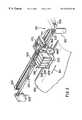
- FIG. 1is a perspective view of a large format inkjet printer/plotter incorporating the features of the present invention
- FIG. 2is a close-up view of the carriage portion of the printer/plotter of FIG. 1 showing a carriage-mounted optical sensor of the present invention
- FIG. 3is a close-up view of the platen portion of the printer/plotter of FIG. 1 showing the carriage portion in phantom lines;
- FIG. 4is a schematic representation of a top view of the carriage showing offsets between individual printheads in the media advance axis and in the carriage scan axis (the phrase “media advance axis” is a shorthand way of referring to the printing-medium advance axis);
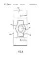
- FIG. 5is a front view of the optical components of the sensor unit of FIG. 4;
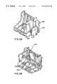
- FIGS. 6A and 6Bare isometric views respectively looking downwardly and upwardly toward the carriage showing the optical sensor and one print cartridge mounted on the carriage;
- FIG. 7schematically shows the nozzle plate of a 600 dpi print cartridge having one column of ink-ejection nozzles separated from another column of ink-ejecting nozzles;
- FIG. 8schematically shows the print cartridge of FIG. 7 in printing position over a print zone
- FIG. 9is a view looking up from the media into a sensor having increased ambient light shielding
- FIG. 10is a schematic drawing showing greatly enlarged a portion of an exemplary test pattern for nozzle functionality
- FIG. 11is a schematic drawing showing a presently preferred scanning technique for a nozzle-out test pattern
- FIG. 12shows a format for an exemplary test pattern of the present invention.
- FIG. 13is a schematic representation of four 600 dpi printheads in an aligned arrangement as used in a presently preferred printhead implementation.
- the inventionprovides a method of monitoring and controlling the quality of pen markings on a plotting medium by optically sensing across a sample line or test-pattern module drawn on an actual medium.
- a customized optical sensorfor monitoring plotter performance by sensing the quality of lines drawn on a medium.
- An LED emitting a green light beamis angularly directed toward an underlying line so as to reflect into an optical sensor which measures the print contrast ratio of a point on the line.
- Circuitmeans amplify and filter the signal generated by the optical sensor.
- a green LEDis used for sensing sample patterns printed by each of the black (K), cyan (C) and magenta (M) printheads, while a blue LED is used for sensing sample patterns printed by the yellow (Y) printhead.
- a light tube on a carriage-mounted optical sensorhas inner walls which help direct light from an LED toward an area surrounding a point under the sensor, and outer walls which help block out undesirable external light from being reflected from the area surrounding a point under the sensor into the photocell.
- the inventioncontemplates optical sensing of different color markings on media using different color light, and raster “lines” (i.e. bars) printed on a pixel grid by an inkjet printer/plotter.
- FIG. 1is a perspective view of an inkjet printer/plotter 210 having a housing 212 mounted on a stand 214 .
- the housinghas left and right drive mechanism enclosures 216 and 218 .
- a control panel 220is mounted on the right enclosure 218 .
- a carriage assembly 300illustrated in phantom under a cover 222 , is adapted for reciprocal motion along a carriage bar 224 , also shown in phantom.
- the position of the carriage assembly 300 in a horizontal or carriage scan axisis determined by a carriage positioning mechanism 310 with respect to an encoder strip 320 (see FIG. 2 ).
- a print medium 330 such as paperis positioned along a vertical or media axis by a media axis drive mechanism (not shown).
- the media axisis called the X axis denoted as 201
- the scan axisis called the Y axis denoted as 301 .
- FIG. 2is a perspective view of the carriage assembly 300 , the carriage positioning mechanism 310 and the encoder strip 320 .
- the carriage positioning mechanism 310includes a carriage position motor 312 which has a shaft 314 which drives a belt 324 which is secured by idler 326 and which is attached to the carriage 300 .
- the position of the carriage assembly in the scan axisis determined precisely by the encoder strip 320 .
- the encoder strip 320is secured by a first stanchion 328 on one end and a second stanchion 329 on the other end.
- An optical reader(not shown) is disposed on the carriage assembly and provides carriage position signals which are utilized by the invention to achieve optimal image registration in the manner described below.
- FIG. 3is perspective view of a simplified representation of a media positioning system 350 which can be utilized in the inventive printer.
- the media positioning system 350includes a motor 352 which is normal to and drives a media roller 354 .
- the position of the media roller 354is determined by a media position encoder 356 on the motor.
- An optical reader 360senses the position of the encoder 356 and provides a plurality of output pulses which indirectly determines the position of the roller 354 and, therefore, the position of the media 230 in the X axis.
- the media and carriage position informationis provided to a processor on a circuit board 370 disposed on the carriage assembly 100 for use in connection with printhead alignment techniques of the present invention.
- the printer 210has four inkjet print cartridges 302 , 304 , 306 , and 308 that store ink of different colors, e.g., black, magenta, cyan and yellow ink, respectively.
- inkjet print cartridges 302 , 304 , 306 , and 308that store ink of different colors, e.g., black, magenta, cyan and yellow ink, respectively.
- selected nozzles in the inkjet print cartridges 302 , 304 , 306 , and 308are activated and ink is applies to the medium 230 .
- the colors from the three color cartridgesare mixed to obtain any other particular color.
- Sample lines 240are typically printed on the media 230 prior to doing an actual printout in order to allow the optical sensor 400 to pass over and scan across the lines as part of the initial calibration.
- the carriage assembly 300positions the inkjet print cartridges and holds the circuitry required for interface to the ink firing circuits in the print cartridges.
- the carriage assembly 300includes a carriage 301 adapted for reciprocal motion on front and rear slider rods 303 , 305 .
- FIG. 4shows a presently preferred embodiment of printheads each having two groups of nozzles with a column offset 410 .
- the optical sensor 400is designed for precise positioning of all of its optical components.
- the sensor unitincludes a photocell 420 , holder 422 , cover 424 , lens 426 , and light source such as two LEDs 428 , 430 .
- a protective casing 440which also acts as an ESD shield for sensor components is provided for attachment to the carriage.
- FIG. 9An optical sensor unit having increased shielding against ambient light is shown in FIG. 9, including a housing 102 , lenses 104 , green light LED 106 , and blue light LED 108 .
- the previous external perimeter of the shieldingis shown in dotted lines 110 , relative to which the new version of an enlarged shielding 112 provides improved optical performance.
- FIG. 10shows a preferred arrangement of markings, each group 120 , 122 , 124 of marks being fired solely by a one particular nozzle respectively during successive multiple passes of the printhead across the printing medium.
- a two-pixel vertical (x-axis) advance between bidirectional passes across the mediumis used to generate the patterns of the printing medium. It is this two-pixel advance that produces the blank pixel rows, between the approximately twenty rows of horizontally adjacent inked pixels seen in the upper portion of FIG. 12 .
- Groups or test pattern modules 120 , 122are represented as being somewhat solid in ink drops from two good nozzles, respectively, while module or group 124 is virtually nonexistent thereby indicating a nonfiring nozzle.
- FIG. 11shows a preferred sequence of sensor scanning, with six complete one-way scans being sufficient to pass over 240 separate test-pattern modules or groups of markings representing output from 240 individual nozzles, respectively.
- the green lightis used for illumination of the magenta, cyan and black patterns during optical sensing, while a blue light is used for illumination of the yellow pattern (sometimes printed against a cyan background for better contrast). Because the contrast sensed for the yellow test pattern is much weaker than for the other colors, it was found preferable to use a separate stronger amplification circuit for the yellow patterns in order to provide the same performance as with the other color inks.
- FIG. 12illustrates the layout and detailed specifications for a recent specific implementation of the present invention.
- the patternshave been successfully used with two hundred forty active nozzles on each of four 600 dpi printheads schematically shown in FIG. 13 in their aligned configuration on an inkjet printer carriage.
Landscapes
- Ink Jet (AREA)
- Particle Formation And Scattering Control In Inkjet Printers (AREA)
- Plural Heterocyclic Compounds (AREA)
Abstract
Description
Claims (24)
Priority Applications (5)
| Application Number | Priority Date | Filing Date | Title |
|---|---|---|---|
| US08/811,412US6352331B1 (en) | 1997-03-04 | 1997-03-04 | Detection of non-firing printhead nozzles by optical scanning of a test pattern |
| JP10049475AJPH10258503A (en) | 1997-03-04 | 1998-03-02 | Device for detecting nozzle function in ink jet printer |
| DE69810526TDE69810526T9 (en) | 1997-03-04 | 1998-03-03 | Detection of jet nozzle defects by optically scanning a sample |
| ES98301571TES2186968T3 (en) | 1997-03-04 | 1998-03-03 | DETECTION OF THE FUNCTIONALITY OF THE NOZZLES OF A PRINT HEAD BY OPTICAL EXPLORATION OF A TEST DESIGN. |
| EP98301571AEP0863012B1 (en) | 1997-03-04 | 1998-03-03 | Detection of printhead nozzle functionality by optical scanning of a test pattern |
Applications Claiming Priority (1)
| Application Number | Priority Date | Filing Date | Title |
|---|---|---|---|
| US08/811,412US6352331B1 (en) | 1997-03-04 | 1997-03-04 | Detection of non-firing printhead nozzles by optical scanning of a test pattern |
Publications (1)
| Publication Number | Publication Date |
|---|---|
| US6352331B1true US6352331B1 (en) | 2002-03-05 |
Family
ID=25206485
Family Applications (1)
| Application Number | Title | Priority Date | Filing Date |
|---|---|---|---|
| US08/811,412Expired - LifetimeUS6352331B1 (en) | 1997-03-04 | 1997-03-04 | Detection of non-firing printhead nozzles by optical scanning of a test pattern |
Country Status (5)
| Country | Link |
|---|---|
| US (1) | US6352331B1 (en) |
| EP (1) | EP0863012B1 (en) |
| JP (1) | JPH10258503A (en) |
| DE (1) | DE69810526T9 (en) |
| ES (1) | ES2186968T3 (en) |
Cited By (40)
| Publication number | Priority date | Publication date | Assignee | Title |
|---|---|---|---|---|
| US6565185B1 (en)* | 1999-09-29 | 2003-05-20 | Seiko Epson Corporation | Nozzle testing before and after nozzle cleaning |
| US6637853B1 (en)* | 1999-07-01 | 2003-10-28 | Lexmark International, Inc. | Faulty nozzle detection in an ink jet printer by printing test patterns and scanning with a fixed optical sensor |
| EP1359027A2 (en) | 2002-04-30 | 2003-11-05 | Hewlett-Packard Company | Fluid delivery techniques with improved reliability |
| US6652080B2 (en) | 2002-04-30 | 2003-11-25 | Hewlett-Packard Development Company, Lp. | Re-circulating fluid delivery system |
| US20040075708A1 (en)* | 2002-10-18 | 2004-04-22 | Konica Minolta Holdings, Inc. | Inkjet recording apparatus |
| US20050035989A1 (en)* | 2003-08-13 | 2005-02-17 | Konica Minolta Holdings, Inc. | Inkjet recording apparatus and recording medium movement control method |
| US20050099447A1 (en)* | 2003-11-11 | 2005-05-12 | Hsu Juei T. | Method and apparatus for detecting faulty nozzles |
| US20050151796A1 (en)* | 2004-01-09 | 2005-07-14 | Brother Kogyo Kabushiki Kaisha | Ink-jet recording apparatus |
| US20050225588A1 (en)* | 2004-04-12 | 2005-10-13 | King David G | Method and apparatus for nozzle map memory storage on a printhead |
| US7055925B2 (en) | 2003-07-31 | 2006-06-06 | Hewlett-Packard Development Company, L.P. | Calibration and measurement techniques for printers |
| US20060139670A1 (en)* | 2004-12-27 | 2006-06-29 | Hoblit Robert S | Method and system for correcting output of printer devices |
| US20070040884A1 (en)* | 2005-08-18 | 2007-02-22 | Funai Electric Co., Ltd. | Ink jet printer |
| US20070052770A1 (en)* | 2005-09-07 | 2007-03-08 | Jason Guhse | Fluid reservoir connector |
| US20070120885A1 (en)* | 2005-11-28 | 2007-05-31 | Jin-Wook Jeong | Method and device to detect defective nozzle of wide array head |
| US20090153602A1 (en)* | 2007-12-18 | 2009-06-18 | Thomas Daniel Brown | Printing Cartridge Refill Method And Associated Cartridge Refill System |
| US20090167801A1 (en)* | 2007-12-27 | 2009-07-02 | Brother Kogyo Kabushiki Kaisha | Ink-jet recording apparatus |
| US20110242187A1 (en)* | 2010-04-06 | 2011-10-06 | Xerox Corporation | Test Pattern Effective For Fine Registration Of Inkjet Printheads And Method Of Analysis Of Image Data Corresponding To The Test Pattern In An Inkjet Printer |
| US8157362B1 (en) | 2006-01-30 | 2012-04-17 | Shahar Turgeman | Ink jet printer cartridge refilling method and apparatus |
| US8376516B2 (en) | 2010-04-06 | 2013-02-19 | Xerox Corporation | System and method for operating a web printing system to compensate for dimensional changes in the web |
| US8403466B1 (en) | 2010-04-02 | 2013-03-26 | Shahar Turgeman | Wide format printer cartridge refilling method and apparatus |
| EP2626209A1 (en) | 2012-02-12 | 2013-08-14 | Baumer Inspection GmbH | Method and device for detecting malfunctions of nozzles of an ink-jet printer |
| US8517524B1 (en) | 2006-01-30 | 2013-08-27 | Shahar Turgeman | Ink jet printer cartridge refilling method and apparatus |
| US8585173B2 (en) | 2011-02-14 | 2013-11-19 | Xerox Corporation | Test pattern less perceptible to human observation and method of analysis of image data corresponding to the test pattern in an inkjet printer |
| US8602518B2 (en) | 2010-04-06 | 2013-12-10 | Xerox Corporation | Test pattern effective for coarse registration of inkjet printheads and methods of analysis of image data corresponding to the test pattern in an inkjet printer |
| US8888225B2 (en) | 2013-04-19 | 2014-11-18 | Xerox Corporation | Method for calibrating optical detector operation with marks formed on a moving image receiving surface in a printer |
| US8960868B1 (en) | 2006-01-30 | 2015-02-24 | Shahar Turgeman | Ink predispense processing and cartridge fill method and apparatus |
| US8995022B1 (en) | 2013-12-12 | 2015-03-31 | Kateeva, Inc. | Ink-based layer fabrication using halftoning to control thickness |
| US9010899B2 (en) | 2012-12-27 | 2015-04-21 | Kateeva, Inc. | Techniques for print ink volume control to deposit fluids within precise tolerances |
| US9352561B2 (en) | 2012-12-27 | 2016-05-31 | Kateeva, Inc. | Techniques for print ink droplet measurement and control to deposit fluids within precise tolerances |
| JP2016210020A (en)* | 2015-04-30 | 2016-12-15 | ブラザー工業株式会社 | Liquid ejection device |
| US9700908B2 (en) | 2012-12-27 | 2017-07-11 | Kateeva, Inc. | Techniques for arrayed printing of a permanent layer with improved speed and accuracy |
| US9718268B1 (en) | 2006-01-30 | 2017-08-01 | Shahar Turgeman | Ink printing system comprising groups of inks, each group having a unique ink base composition |
| US9832428B2 (en) | 2012-12-27 | 2017-11-28 | Kateeva, Inc. | Fast measurement of droplet parameters in industrial printing system |
| CN108454234A (en)* | 2017-02-21 | 2018-08-28 | 精工爱普生株式会社 | The production method of test pattern, test pattern, printing equipment, storage medium |
| US10144222B1 (en) | 2006-01-30 | 2018-12-04 | Shahar Turgeman | Ink printing system |
| US11061351B2 (en)* | 2019-01-09 | 2021-07-13 | Canon Kabushiki Kaisha | Measuring device and image forming apparatus |
| US11141752B2 (en) | 2012-12-27 | 2021-10-12 | Kateeva, Inc. | Techniques for arrayed printing of a permanent layer with improved speed and accuracy |
| US11673155B2 (en) | 2012-12-27 | 2023-06-13 | Kateeva, Inc. | Techniques for arrayed printing of a permanent layer with improved speed and accuracy |
| CN119567728A (en)* | 2023-09-07 | 2025-03-07 | 深圳市汉森软件股份有限公司 | Nozzle detection method, device and apparatus based on ink color adjustment irradiation light |
| US12330178B2 (en) | 2012-12-27 | 2025-06-17 | Kateeva, Inc. | Techniques for arrayed printing of a permanent layer with improved speed and accuracy |
Families Citing this family (14)
| Publication number | Priority date | Publication date | Assignee | Title |
|---|---|---|---|---|
| JP4258685B2 (en)* | 1998-09-22 | 2009-04-30 | セーレン株式会社 | Inkjet nozzle defect detection method and apparatus |
| US6215557B1 (en) | 1999-07-01 | 2001-04-10 | Lexmark International, Inc. | Entry of missing nozzle information in an ink jet printer |
| FR2801836B1 (en) | 1999-12-03 | 2002-02-01 | Imaje Sa | SIMPLIFIED MANUFACTURING PRINTER AND METHOD OF MAKING |
| FR2801835B1 (en) | 1999-12-03 | 2002-02-01 | Imaje Sa | PROCESS AND PRINTER WITH SUBSTRATE ADVANCE CONTROL |
| US6623096B1 (en)* | 2000-07-28 | 2003-09-23 | Hewlett-Packard Company | Techniques for measuring the position of marks on media and for aligning inkjet devices |
| JP2004521784A (en)* | 2001-04-04 | 2004-07-22 | エイプリオン・デジタル・リミテッド | Banding compensation method and banding compensation system for inkjet printer |
| GB2384931B (en) | 2002-01-30 | 2005-06-29 | Hewlett Packard Co | Printer device and method |
| EP1431043B1 (en)* | 2002-12-20 | 2010-12-15 | Brother Kogyo Kabushiki Kaisha | A method of printing a test pattern and an image forming device therefor |
| US7438378B2 (en) | 2004-08-30 | 2008-10-21 | Pitney Bowes Inc. | Fluorescent ink detector |
| US7878615B2 (en) | 2005-12-14 | 2011-02-01 | Pitney Bowes Inc. | System and method for detecting defective ink jet nozzles |
| US9623671B2 (en) | 2010-05-24 | 2017-04-18 | Canon Kabushiki Kaisha | Image processor, printing apparatus, and image processing method |
| JP5473779B2 (en)* | 2010-05-24 | 2014-04-16 | キヤノン株式会社 | Image processing apparatus and image processing method |
| JP6033005B2 (en)* | 2012-03-09 | 2016-11-30 | キヤノン株式会社 | Recording device and sensor unit |
| JP6016385B2 (en)* | 2012-03-09 | 2016-10-26 | キヤノン株式会社 | Recording device and sensor unit |
Citations (13)
| Publication number | Priority date | Publication date | Assignee | Title |
|---|---|---|---|---|
| JPS57110455A (en)* | 1980-12-27 | 1982-07-09 | Ricoh Co Ltd | Ink jet printing apparatus |
| JPS58162350A (en)* | 1982-03-23 | 1983-09-27 | Fanuc Ltd | Printer |
| DE3246707A1 (en) | 1982-12-17 | 1984-06-20 | Olympia Werke Ag, 2940 Wilhelmshaven | Arrangement for testing jet outlet openings on ink print heads for blockage or contamination in ink printing mechanisms |
| JPS63260448A (en)* | 1987-04-17 | 1988-10-27 | Seiko Epson Corp | How to detect jetting errors in inkjet printers |
| JPH02194955A (en)* | 1989-01-24 | 1990-08-01 | Canon Inc | Ink jet recorder |
| US4977459A (en) | 1988-06-23 | 1990-12-11 | Canon Kabushiki Kaisha | Ink-jet recording apparatus with mechanism for automatically regulating a recording head |
| JPH03104678A (en) | 1989-09-19 | 1991-05-01 | Shimadzu Corp | Printer |
| US5109239A (en)* | 1989-01-31 | 1992-04-28 | Hewlett-Packard Company | Inter pen offset determination and compensation in multi-pen ink jet printing systems |
| JPH04169239A (en) | 1990-11-01 | 1992-06-17 | Mita Ind Co Ltd | Ink-jet record device |
| EP0500281A2 (en) | 1991-02-20 | 1992-08-26 | Canon Kabushiki Kaisha | Recording apparatus with automatic recovery function |
| JPH0624008A (en) | 1992-07-09 | 1994-02-01 | Canon Inc | Ink jet recording device |
| US5448269A (en) | 1993-04-30 | 1995-09-05 | Hewlett-Packard Company | Multiple inkjet cartridge alignment for bidirectional printing by scanning a reference pattern |
| US5508826A (en)* | 1993-04-27 | 1996-04-16 | Lloyd; William J. | Method and apparatus for calibrated digital printing using a four by four transformation matrix |
- 1997
- 1997-03-04USUS08/811,412patent/US6352331B1/ennot_activeExpired - Lifetime
- 1998
- 1998-03-02JPJP10049475Apatent/JPH10258503A/enactivePending
- 1998-03-03EPEP98301571Apatent/EP0863012B1/ennot_activeExpired - Lifetime
- 1998-03-03DEDE69810526Tpatent/DE69810526T9/ennot_activeExpired - Fee Related
- 1998-03-03ESES98301571Tpatent/ES2186968T3/ennot_activeExpired - Lifetime
Patent Citations (13)
| Publication number | Priority date | Publication date | Assignee | Title |
|---|---|---|---|---|
| JPS57110455A (en)* | 1980-12-27 | 1982-07-09 | Ricoh Co Ltd | Ink jet printing apparatus |
| JPS58162350A (en)* | 1982-03-23 | 1983-09-27 | Fanuc Ltd | Printer |
| DE3246707A1 (en) | 1982-12-17 | 1984-06-20 | Olympia Werke Ag, 2940 Wilhelmshaven | Arrangement for testing jet outlet openings on ink print heads for blockage or contamination in ink printing mechanisms |
| JPS63260448A (en)* | 1987-04-17 | 1988-10-27 | Seiko Epson Corp | How to detect jetting errors in inkjet printers |
| US4977459A (en) | 1988-06-23 | 1990-12-11 | Canon Kabushiki Kaisha | Ink-jet recording apparatus with mechanism for automatically regulating a recording head |
| JPH02194955A (en)* | 1989-01-24 | 1990-08-01 | Canon Inc | Ink jet recorder |
| US5109239A (en)* | 1989-01-31 | 1992-04-28 | Hewlett-Packard Company | Inter pen offset determination and compensation in multi-pen ink jet printing systems |
| JPH03104678A (en) | 1989-09-19 | 1991-05-01 | Shimadzu Corp | Printer |
| JPH04169239A (en) | 1990-11-01 | 1992-06-17 | Mita Ind Co Ltd | Ink-jet record device |
| EP0500281A2 (en) | 1991-02-20 | 1992-08-26 | Canon Kabushiki Kaisha | Recording apparatus with automatic recovery function |
| JPH0624008A (en) | 1992-07-09 | 1994-02-01 | Canon Inc | Ink jet recording device |
| US5508826A (en)* | 1993-04-27 | 1996-04-16 | Lloyd; William J. | Method and apparatus for calibrated digital printing using a four by four transformation matrix |
| US5448269A (en) | 1993-04-30 | 1995-09-05 | Hewlett-Packard Company | Multiple inkjet cartridge alignment for bidirectional printing by scanning a reference pattern |
Cited By (96)
| Publication number | Priority date | Publication date | Assignee | Title |
|---|---|---|---|---|
| US6637853B1 (en)* | 1999-07-01 | 2003-10-28 | Lexmark International, Inc. | Faulty nozzle detection in an ink jet printer by printing test patterns and scanning with a fixed optical sensor |
| US6565185B1 (en)* | 1999-09-29 | 2003-05-20 | Seiko Epson Corporation | Nozzle testing before and after nozzle cleaning |
| US6764159B2 (en) | 1999-09-29 | 2004-07-20 | Seiko Epson Corporation | Nozzle testing before and after nozzle cleaning |
| EP1621352A2 (en) | 2002-04-30 | 2006-02-01 | Hewlett-Packard Company, A Delaware Corporation | Fluid delivery techniques with improved reliability |
| EP1359027A2 (en) | 2002-04-30 | 2003-11-05 | Hewlett-Packard Company | Fluid delivery techniques with improved reliability |
| US6652080B2 (en) | 2002-04-30 | 2003-11-25 | Hewlett-Packard Development Company, Lp. | Re-circulating fluid delivery system |
| US6752493B2 (en) | 2002-04-30 | 2004-06-22 | Hewlett-Packard Development Company, L.P. | Fluid delivery techniques with improved reliability |
| US20070002090A1 (en)* | 2002-10-18 | 2007-01-04 | Konica Minolta Holdings, Inc. | Inkjet recording apparatus having an adjusting mechanism for adjusting moving of a recording medium |
| US20040075708A1 (en)* | 2002-10-18 | 2004-04-22 | Konica Minolta Holdings, Inc. | Inkjet recording apparatus |
| US7354130B2 (en) | 2002-10-18 | 2008-04-08 | Konica Minolta Holdings, Inc. | Inkjet recording apparatus having an adjusting mechanism for adjusting moving of a recording medium |
| US7118187B2 (en)* | 2002-10-18 | 2006-10-10 | Konica Minolta Holdings, Inc. | Inkjet recording apparatus having an adjusting mechanism for adjusting moving of a recording medium |
| US7055925B2 (en) | 2003-07-31 | 2006-06-06 | Hewlett-Packard Development Company, L.P. | Calibration and measurement techniques for printers |
| US20050035989A1 (en)* | 2003-08-13 | 2005-02-17 | Konica Minolta Holdings, Inc. | Inkjet recording apparatus and recording medium movement control method |
| US7364251B2 (en) | 2003-08-13 | 2008-04-29 | Konica Minolta Holdings, Inc. | Inkjet recording apparatus and recording medium movement control method |
| US20050099447A1 (en)* | 2003-11-11 | 2005-05-12 | Hsu Juei T. | Method and apparatus for detecting faulty nozzles |
| US20050151796A1 (en)* | 2004-01-09 | 2005-07-14 | Brother Kogyo Kabushiki Kaisha | Ink-jet recording apparatus |
| US8500251B2 (en)* | 2004-01-09 | 2013-08-06 | Brother Kogyo Kabushiki Kaisha | Ink-jet recording apparatus |
| US20050225588A1 (en)* | 2004-04-12 | 2005-10-13 | King David G | Method and apparatus for nozzle map memory storage on a printhead |
| US20060139670A1 (en)* | 2004-12-27 | 2006-06-29 | Hoblit Robert S | Method and system for correcting output of printer devices |
| US20070040884A1 (en)* | 2005-08-18 | 2007-02-22 | Funai Electric Co., Ltd. | Ink jet printer |
| US7794073B2 (en)* | 2005-08-18 | 2010-09-14 | Funai Electric Co., Ltd. | Ink jet printer |
| US7980686B2 (en) | 2005-09-07 | 2011-07-19 | Retail Inkjet Solutions, Inc. | Fluid reservoir connector |
| US10011117B2 (en) | 2005-09-07 | 2018-07-03 | Retail Inkjet Solutions, Inc. | Inkjet refilling adapter |
| US20070052748A1 (en)* | 2005-09-07 | 2007-03-08 | Herb Sarnoff | Test system for an inkjet refilling station |
| US20070052770A1 (en)* | 2005-09-07 | 2007-03-08 | Jason Guhse | Fluid reservoir connector |
| US20070051421A1 (en)* | 2005-09-07 | 2007-03-08 | Herb Sarnoff | Inkjet refilling station |
| US20070052777A1 (en)* | 2005-09-07 | 2007-03-08 | Jason Guhse | System for cleaning inkjet cartridges |
| US7540597B2 (en) | 2005-09-07 | 2009-06-02 | Retail Inkjet Solutions, Inc. | Process for refilling inkjet cartridges |
| US9487015B2 (en) | 2005-09-07 | 2016-11-08 | Retail Inkjet Solutions, Inc. | Inkjet refilling adapter |
| US20070052776A1 (en)* | 2005-09-07 | 2007-03-08 | Jason Guhse | Ink reservoir |
| US7708370B2 (en) | 2005-09-07 | 2010-05-04 | Retail Inkjet Solutions, Inc. | Test system for an inkjet refilling station |
| US7780276B2 (en) | 2005-09-07 | 2010-08-24 | Retail Inkjet Solutions, Inc. | System for refilling inkjet cartridges |
| US20070052740A1 (en)* | 2005-09-07 | 2007-03-08 | Jason Guhse | System for refilling inkjet cartridges |
| US7887166B2 (en) | 2005-09-07 | 2011-02-15 | Retail Inkjet Solutions, Inc. | Ink reservoir |
| US7891759B2 (en) | 2005-09-07 | 2011-02-22 | Retail Inkjet Solutions, Inc. | System for cleaning inkjet cartridges |
| US7946316B2 (en) | 2005-09-07 | 2011-05-24 | Retail Inkjet Solutions, Inc. | Inkjet refilling station |
| US8876266B2 (en) | 2005-09-07 | 2014-11-04 | Retail Inkjet Solutions, Inc. | System and method for refilling ink containers |
| US8443853B2 (en) | 2005-09-07 | 2013-05-21 | Retail Inkjet Solutions, Inc. | Inkjet refilling station |
| US8403468B2 (en) | 2005-09-07 | 2013-03-26 | Retail Inkjet Solutions, Inc. | Modular ink cartridge refilling system |
| US20070052767A1 (en)* | 2005-09-07 | 2007-03-08 | Jason Guhse | Process for refilling inkjet cartridges |
| US20070120885A1 (en)* | 2005-11-28 | 2007-05-31 | Jin-Wook Jeong | Method and device to detect defective nozzle of wide array head |
| US8157362B1 (en) | 2006-01-30 | 2012-04-17 | Shahar Turgeman | Ink jet printer cartridge refilling method and apparatus |
| US9718268B1 (en) | 2006-01-30 | 2017-08-01 | Shahar Turgeman | Ink printing system comprising groups of inks, each group having a unique ink base composition |
| US10144222B1 (en) | 2006-01-30 | 2018-12-04 | Shahar Turgeman | Ink printing system |
| US8960868B1 (en) | 2006-01-30 | 2015-02-24 | Shahar Turgeman | Ink predispense processing and cartridge fill method and apparatus |
| US8517524B1 (en) | 2006-01-30 | 2013-08-27 | Shahar Turgeman | Ink jet printer cartridge refilling method and apparatus |
| US20090153602A1 (en)* | 2007-12-18 | 2009-06-18 | Thomas Daniel Brown | Printing Cartridge Refill Method And Associated Cartridge Refill System |
| US8029091B2 (en)* | 2007-12-27 | 2011-10-04 | Brother Kogyo Kabushiki Kaisha | Ink-jet recording apparatus |
| US20090167801A1 (en)* | 2007-12-27 | 2009-07-02 | Brother Kogyo Kabushiki Kaisha | Ink-jet recording apparatus |
| US8567929B1 (en) | 2010-04-02 | 2013-10-29 | Shahar Turgeman | Wide format printer cartridge refilling method and apparatus |
| US8403466B1 (en) | 2010-04-02 | 2013-03-26 | Shahar Turgeman | Wide format printer cartridge refilling method and apparatus |
| US8721033B2 (en) | 2010-04-06 | 2014-05-13 | Xerox Corporation | Method for analyzing image data corresponding to a test pattern effective for fine registration of inkjet printheads in an inkjet printer |
| US8602518B2 (en) | 2010-04-06 | 2013-12-10 | Xerox Corporation | Test pattern effective for coarse registration of inkjet printheads and methods of analysis of image data corresponding to the test pattern in an inkjet printer |
| US20110242187A1 (en)* | 2010-04-06 | 2011-10-06 | Xerox Corporation | Test Pattern Effective For Fine Registration Of Inkjet Printheads And Method Of Analysis Of Image Data Corresponding To The Test Pattern In An Inkjet Printer |
| US8376516B2 (en) | 2010-04-06 | 2013-02-19 | Xerox Corporation | System and method for operating a web printing system to compensate for dimensional changes in the web |
| US8585173B2 (en) | 2011-02-14 | 2013-11-19 | Xerox Corporation | Test pattern less perceptible to human observation and method of analysis of image data corresponding to the test pattern in an inkjet printer |
| EP2626209A1 (en) | 2012-02-12 | 2013-08-14 | Baumer Inspection GmbH | Method and device for detecting malfunctions of nozzles of an ink-jet printer |
| DE102013002254A1 (en) | 2012-02-12 | 2013-08-14 | Baumer Inspection Gmbh | Modular nozzle with monitoring module |
| US11141752B2 (en) | 2012-12-27 | 2021-10-12 | Kateeva, Inc. | Techniques for arrayed printing of a permanent layer with improved speed and accuracy |
| US10797270B2 (en) | 2012-12-27 | 2020-10-06 | Kateeva, Inc. | Nozzle-droplet combination techniques to deposit fluids in substrate locations within precise tolerances |
| US12330178B2 (en) | 2012-12-27 | 2025-06-17 | Kateeva, Inc. | Techniques for arrayed printing of a permanent layer with improved speed and accuracy |
| US12256626B2 (en) | 2012-12-27 | 2025-03-18 | Kateeva, Inc. | Nozzle-droplet combination techniques to deposit fluids in substrate locations within precise tolerances |
| US9537119B2 (en) | 2012-12-27 | 2017-01-03 | Kateeva, Inc. | Nozzle-droplet combination techniques to deposit fluids in substrate locations within precise tolerances |
| US9700908B2 (en) | 2012-12-27 | 2017-07-11 | Kateeva, Inc. | Techniques for arrayed printing of a permanent layer with improved speed and accuracy |
| US9224952B2 (en) | 2012-12-27 | 2015-12-29 | Kateeva, Inc. | Methods of manufacturing electronic display devices employing nozzle-droplet combination techniques to deposit fluids in substrate locations within precise tolerances |
| US11678561B2 (en) | 2012-12-27 | 2023-06-13 | Kateeva, Inc. | Nozzle-droplet combination techniques to deposit fluids in substrate locations within precise tolerances |
| US11673155B2 (en) | 2012-12-27 | 2023-06-13 | Kateeva, Inc. | Techniques for arrayed printing of a permanent layer with improved speed and accuracy |
| US9802403B2 (en) | 2012-12-27 | 2017-10-31 | Kateeva, Inc. | Techniques for print ink droplet measurement and control to deposit fluids within precise tolerances |
| US9832428B2 (en) | 2012-12-27 | 2017-11-28 | Kateeva, Inc. | Fast measurement of droplet parameters in industrial printing system |
| US11489146B2 (en) | 2012-12-27 | 2022-11-01 | Kateeva, Inc. | Techniques for print ink droplet measurement and control to deposit fluids within precise tolerances |
| US9010899B2 (en) | 2012-12-27 | 2015-04-21 | Kateeva, Inc. | Techniques for print ink volume control to deposit fluids within precise tolerances |
| US11233226B2 (en) | 2012-12-27 | 2022-01-25 | Kateeva, Inc. | Nozzle-droplet combination techniques to deposit fluids in substrate locations within precise tolerances |
| US11167303B2 (en) | 2012-12-27 | 2021-11-09 | Kateeva, Inc. | Techniques for arrayed printing of a permanent layer with improved speed and accuracy |
| US10950826B2 (en) | 2012-12-27 | 2021-03-16 | Kateeva, Inc. | Techniques for print ink droplet measurement and control to deposit fluids within precise tolerances |
| US9352561B2 (en) | 2012-12-27 | 2016-05-31 | Kateeva, Inc. | Techniques for print ink droplet measurement and control to deposit fluids within precise tolerances |
| US10784470B2 (en) | 2012-12-27 | 2020-09-22 | Kateeva, Inc. | Techniques for print ink droplet measurement and control to deposit fluids within precise tolerances |
| US10784472B2 (en) | 2012-12-27 | 2020-09-22 | Kateeva, Inc. | Nozzle-droplet combination techniques to deposit fluids in substrate locations within precise tolerances |
| US8888225B2 (en) | 2013-04-19 | 2014-11-18 | Xerox Corporation | Method for calibrating optical detector operation with marks formed on a moving image receiving surface in a printer |
| US12334402B2 (en) | 2013-12-12 | 2025-06-17 | Kateeva, Inc. | Fabrication of thin-film encapsulation layer for light-emitting device |
| US10522425B2 (en) | 2013-12-12 | 2019-12-31 | Kateeva, Inc. | Fabrication of thin-film encapsulation layer for light emitting device |
| US10586742B2 (en) | 2013-12-12 | 2020-03-10 | Kateeva, Inc. | Fabrication of thin-film encapsulation layer for light emitting device |
| US11088035B2 (en) | 2013-12-12 | 2021-08-10 | Kateeva, Inc. | Fabrication of thin-film encapsulation layer for light emitting device |
| US10811324B2 (en) | 2013-12-12 | 2020-10-20 | Kateeva, Inc. | Fabrication of thin-film encapsulation layer for light emitting device |
| US8995022B1 (en) | 2013-12-12 | 2015-03-31 | Kateeva, Inc. | Ink-based layer fabrication using halftoning to control thickness |
| US9496519B2 (en) | 2013-12-12 | 2016-11-15 | Kateeva, Inc. | Encapsulation of components of electronic device using halftoning to control thickness |
| US11456220B2 (en) | 2013-12-12 | 2022-09-27 | Kateeva, Inc. | Techniques for layer fencing to improve edge linearity |
| US9831473B2 (en) | 2013-12-12 | 2017-11-28 | Kateeva, Inc. | Encapsulation layer thickness regulation in light emitting device |
| US11551982B2 (en) | 2013-12-12 | 2023-01-10 | Kateeva, Inc. | Fabrication of thin-film encapsulation layer for light-emitting device |
| US9806298B2 (en) | 2013-12-12 | 2017-10-31 | Kateeva, Inc. | Techniques for edge management of printed layers in the fabrication of a light emitting device |
| US9755186B2 (en) | 2013-12-12 | 2017-09-05 | Kateeva, Inc. | Calibration of layer thickness and ink volume in fabrication of encapsulation layer for light emitting device |
| JP2016210020A (en)* | 2015-04-30 | 2016-12-15 | ブラザー工業株式会社 | Liquid ejection device |
| CN108454234B (en)* | 2017-02-21 | 2021-08-03 | 精工爱普生株式会社 | Test pattern production method, test pattern, printing device, storage medium |
| CN108454234A (en)* | 2017-02-21 | 2018-08-28 | 精工爱普生株式会社 | The production method of test pattern, test pattern, printing equipment, storage medium |
| US11835901B2 (en) | 2019-01-09 | 2023-12-05 | Canon Kabushiki Kaisha | Measuring device and image forming apparatus |
| US11061351B2 (en)* | 2019-01-09 | 2021-07-13 | Canon Kabushiki Kaisha | Measuring device and image forming apparatus |
| CN119567728A (en)* | 2023-09-07 | 2025-03-07 | 深圳市汉森软件股份有限公司 | Nozzle detection method, device and apparatus based on ink color adjustment irradiation light |
Also Published As
| Publication number | Publication date |
|---|---|
| JPH10258503A (en) | 1998-09-29 |
| ES2186968T3 (en) | 2003-05-16 |
| EP0863012A1 (en) | 1998-09-09 |
| EP0863012B1 (en) | 2003-01-08 |
| DE69810526T2 (en) | 2003-11-06 |
| DE69810526T9 (en) | 2004-10-14 |
| DE69810526D1 (en) | 2003-02-13 |
Similar Documents
| Publication | Publication Date | Title |
|---|---|---|
| US6352331B1 (en) | Detection of non-firing printhead nozzles by optical scanning of a test pattern | |
| US7055925B2 (en) | Calibration and measurement techniques for printers | |
| US5835108A (en) | Calibration technique for mis-directed inkjet printhead nozzles | |
| US5975674A (en) | Optical path optimization for light transmission and reflection in a carriage-mounted inkjet printer sensor | |
| EP1889722B1 (en) | Array type inkjet printer and method for determining condition of nozzles thereof | |
| JP3514508B2 (en) | Reference pattern for inkjet cartridge alignment | |
| EP0983855A2 (en) | Dot substitution to compensate for failed ink jet nozzles | |
| US6523920B2 (en) | Combination ink jet pen and optical scanner head and methods of improving print quality | |
| JP5063327B2 (en) | Inkjet recording apparatus and adjustment value acquisition method | |
| EP1176802A2 (en) | Techniques for measuring the position of marks on media and for aligning inkjet devices | |
| JPH071725A (en) | Device for alignment of ink jet cartridge | |
| US20040212648A1 (en) | Ink jet printer | |
| JP2004001558A (en) | Device for arranging inkjet cartridge | |
| US7287824B2 (en) | Method and apparatus for assessing nozzle health | |
| JP5898591B2 (en) | Method and system for in-document detection of functionally poor or missing ink jets in an ink jet printer | |
| US6669322B2 (en) | Method and system for calibrating ink ejection elements in an image forming device | |
| JP2000037866A (en) | Ink-jet printer and method for compensating for malfunctioning and inoperative ink nozzle at print head | |
| EP1065056B1 (en) | Dot skip inspecting method and printer, and recorded medium on which program therefor is recorded | |
| US7052102B2 (en) | Detecting fixer in hardcopy apparatus | |
| US6485124B1 (en) | Optical alignment method and detector | |
| JPH06340065A (en) | Ink jet cartridge arranging method | |
| US20030095162A1 (en) | Ink ejection determining device, inkjet printer, storage medium, computer system, and ink ejection determining method | |
| US20050146548A1 (en) | Method and apparatus of operating a printer | |
| JP2007152784A (en) | Inkjet printer registration adjustment method | |
| JP4122729B2 (en) | Image forming apparatus and image forming position correcting method |
Legal Events
| Date | Code | Title | Description |
|---|---|---|---|
| AS | Assignment | Owner name:HEWLETT-PACKARD COMPANY, CALIFORNIA Free format text:ASSIGNMENT OF ASSIGNORS INTEREST;ASSIGNOR:ARMIJO, CHRIS T.;REEL/FRAME:008722/0636 Effective date:19970805 | |
| AS | Assignment | Owner name:HEWLETT-PACKARD COMPANY, CALIFORNIA Free format text:ASSIGNMENT OF ASSIGNORS INTEREST;ASSIGNOR:HEWLETT-PACKARD ESPANOLA, S.A.;REEL/FRAME:008890/0574 Effective date:19971215 | |
| AS | Assignment | Owner name:HEWLETT-PACKARD COMPANY, COLORADO Free format text:MERGER;ASSIGNOR:HEWLETT-PACKARD COMPANY;REEL/FRAME:011523/0469 Effective date:19980520 | |
| AS | Assignment | Owner name:HEWLETT-PACKARD COMPANY, COLORADO Free format text:ASSIGNMENT OF ASSIGNORS INTEREST;ASSIGNOR:HEWLETT-PACKARD ESPANOLA, S.A.;REEL/FRAME:012568/0228 Effective date:20010517 | |
| STCF | Information on status: patent grant | Free format text:PATENTED CASE | |
| FPAY | Fee payment | Year of fee payment:4 | |
| FPAY | Fee payment | Year of fee payment:8 | |
| AS | Assignment | Owner name:HEWLETT-PACKARD DEVELOPMENT COMPANY, L.P., TEXAS Free format text:ASSIGNMENT OF ASSIGNORS INTEREST;ASSIGNOR:HEWLETT-PACKARD COMPANY;REEL/FRAME:026945/0699 Effective date:20030131 | |
| FPAY | Fee payment | Year of fee payment:12 |