US6352226B1 - Monitor lift apparatus - Google Patents
Monitor lift apparatusDownload PDFInfo
- Publication number
- US6352226B1 US6352226B1US09/563,799US56379900AUS6352226B1US 6352226 B1US6352226 B1US 6352226B1US 56379900 AUS56379900 AUS 56379900AUS 6352226 B1US6352226 B1US 6352226B1
- Authority
- US
- United States
- Prior art keywords
- carriage
- frame
- monitor
- lift apparatus
- rotary drive
- Prior art date
- Legal status (The legal status is an assumption and is not a legal conclusion. Google has not performed a legal analysis and makes no representation as to the accuracy of the status listed.)
- Expired - Lifetime
Links
- 230000000694effectsEffects0.000claimsabstractdescription13
- 230000004913activationEffects0.000claimsdescription4
- 230000013011matingEffects0.000claimsdescription3
- 230000003213activating effectEffects0.000description4
- 238000000034methodMethods0.000description4
- 230000003287optical effectEffects0.000description3
- 230000001105regulatory effectEffects0.000description1
Images


Classifications
- B—PERFORMING OPERATIONS; TRANSPORTING
- B64—AIRCRAFT; AVIATION; COSMONAUTICS
- B64D—EQUIPMENT FOR FITTING IN OR TO AIRCRAFT; FLIGHT SUITS; PARACHUTES; ARRANGEMENT OR MOUNTING OF POWER PLANTS OR PROPULSION TRANSMISSIONS IN AIRCRAFT
- B64D11/00—Passenger or crew accommodation; Flight-deck installations not otherwise provided for
- B64D11/0015—Arrangements for entertainment or communications, e.g. radio, television
- B64D11/00153—Monitors mounted on or in the seat other than the seat back
- F—MECHANICAL ENGINEERING; LIGHTING; HEATING; WEAPONS; BLASTING
- F16—ENGINEERING ELEMENTS AND UNITS; GENERAL MEASURES FOR PRODUCING AND MAINTAINING EFFECTIVE FUNCTIONING OF MACHINES OR INSTALLATIONS; THERMAL INSULATION IN GENERAL
- F16M—FRAMES, CASINGS OR BEDS OF ENGINES, MACHINES OR APPARATUS, NOT SPECIFIC TO ENGINES, MACHINES OR APPARATUS PROVIDED FOR ELSEWHERE; STANDS; SUPPORTS
- F16M11/00—Stands or trestles as supports for apparatus or articles placed thereon ; Stands for scientific apparatus such as gravitational force meters
- F16M11/02—Heads
- F16M11/04—Means for attachment of apparatus; Means allowing adjustment of the apparatus relatively to the stand
- F16M11/06—Means for attachment of apparatus; Means allowing adjustment of the apparatus relatively to the stand allowing pivoting
- F16M11/08—Means for attachment of apparatus; Means allowing adjustment of the apparatus relatively to the stand allowing pivoting around a vertical axis, e.g. panoramic heads
- F—MECHANICAL ENGINEERING; LIGHTING; HEATING; WEAPONS; BLASTING
- F16—ENGINEERING ELEMENTS AND UNITS; GENERAL MEASURES FOR PRODUCING AND MAINTAINING EFFECTIVE FUNCTIONING OF MACHINES OR INSTALLATIONS; THERMAL INSULATION IN GENERAL
- F16M—FRAMES, CASINGS OR BEDS OF ENGINES, MACHINES OR APPARATUS, NOT SPECIFIC TO ENGINES, MACHINES OR APPARATUS PROVIDED FOR ELSEWHERE; STANDS; SUPPORTS
- F16M11/00—Stands or trestles as supports for apparatus or articles placed thereon ; Stands for scientific apparatus such as gravitational force meters
- F16M11/02—Heads
- F16M11/18—Heads with mechanism for moving the apparatus relatively to the stand
- F—MECHANICAL ENGINEERING; LIGHTING; HEATING; WEAPONS; BLASTING
- F16—ENGINEERING ELEMENTS AND UNITS; GENERAL MEASURES FOR PRODUCING AND MAINTAINING EFFECTIVE FUNCTIONING OF MACHINES OR INSTALLATIONS; THERMAL INSULATION IN GENERAL
- F16M—FRAMES, CASINGS OR BEDS OF ENGINES, MACHINES OR APPARATUS, NOT SPECIFIC TO ENGINES, MACHINES OR APPARATUS PROVIDED FOR ELSEWHERE; STANDS; SUPPORTS
- F16M11/00—Stands or trestles as supports for apparatus or articles placed thereon ; Stands for scientific apparatus such as gravitational force meters
- F16M11/20—Undercarriages with or without wheels
- F16M11/24—Undercarriages with or without wheels changeable in height or length of legs, also for transport only, e.g. by means of tubes screwed into each other
- Y—GENERAL TAGGING OF NEW TECHNOLOGICAL DEVELOPMENTS; GENERAL TAGGING OF CROSS-SECTIONAL TECHNOLOGIES SPANNING OVER SEVERAL SECTIONS OF THE IPC; TECHNICAL SUBJECTS COVERED BY FORMER USPC CROSS-REFERENCE ART COLLECTIONS [XRACs] AND DIGESTS
- Y10—TECHNICAL SUBJECTS COVERED BY FORMER USPC
- Y10S—TECHNICAL SUBJECTS COVERED BY FORMER USPC CROSS-REFERENCE ART COLLECTIONS [XRACs] AND DIGESTS
- Y10S248/00—Supports
- Y10S248/917—Video display screen support
Definitions
- This inventionrelates generally to display monitor lift systems useful where space is limited and the monitor may need to be stowed out of the way when not in use. More particularly, it concerns a monitor lift apparatus which employs a flexible track configured to define a path for traverse by a drive element to effect travel of a monitor between a stowed position and a presented position.
- display monitorsare important to many travelers, both for entertainment and as an effective business tool.
- monitorstypically must be provided with the capability of being stowed out of the way of the passengers and crew when not in use.
- Such monitorsalso preferably are deployable/stowable quickly and are easily positionable by the user during flight.
- Onboard display monitorsthus typically are mounted as nearby as possible to passengers, often being built into the passenger's seat or an adjacent structure.
- monitor lift apparatuswhich accommodates easy deployment/stowage of a monitor without utilizing excessive amounts of space. It also would be useful to provide a monitor lift apparatus which provides for secure stowage of the monitor when not in use.
- the invented lift apparatusincludes a frame and a carriage-mounted monitor configured for travel between a stowed position and a presented position along a flexible track.
- the carriagetypically includes a rotary drive element which traverses the flexible track to effect travel of the carriage and monitor between the stowed and presented positions.
- the flexible trackmay take the form of a chain, belt, or cable, and typically extends between upper and lower ends of the frame so as to provide for vertical deployment/stowage of the monitor.
- the carriagemay include first and second rotary drive elements, the second drive element being laterally offset from the first rotary drive element such that the flexible track extends about the first and second drive elements along a generally S-shaped path.
- the first rotary drive elementserves to drive the carriage along the flexible track.
- the second rotary drive elementacts as a idler to adjust tension in the flexible track and to provide sufficient engagement between the rotary drive elements and the flexible track. This configuration maintains tension in the flexible track.
- the monitormay be secured in position using a latch pin which is mounted on the carriage to selectively engage the frame.
- the framemay define a one or more detents for receipt of the latch pin.
- the latch pinis biased toward a deployed orientation wherein the latch pin engages the frame, but a solenoid in operative relation with the latch pin is configured selectively to remove the latch pin from the deployed orientation.
- the solenoidmay be activated/deactivated based on information provided by one or more sensors which detect the position of the carriage and/or monitor.
- FIG. 1is an isometric view depicting a monitor lift apparatus constructed in accordance with the present invention, the monitor/carriage being shown in a deployed position.
- FIG. 2is a front view of the monitor lift apparatus shown in FIG. 1, but with the monitor/carriage in a stowed position.
- FIG. 2Ais a fragmentary front view showing a latch pin of the monitor lift apparatus in a non-deployed orientation.
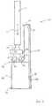
- FIG. 3is a somewhat simplified side sectional view of the monitor lift apparatus taken along lines 3 — 3 of FIG. 2 .
- FIG. 4is a flow chart showing a method whereby a monitor carriage is moved between a stowed position where the carriage is secured in place via a retractable latch and a presented position where the carriage is secured in place via the retractable latch pin.
- Apparatus 10may be seen to include a generally rectangular, substantially open frame 20 including a base plate 22 , a top plate 24 , right and left side-walls 26 , 27 , and a rear wall 28 .
- the frameis configured for placement in a cavity formed in an aircraft seat, bulkhead, or adjacent structure.
- a monitor 12is mounted on the frame, typically via a mounting structure such as carriage 30 , which carries the monitor between a presented position (FIG. 1) and a stowed position (FIG. 2) as will be described herein.
- the monitoralso typically is pivotal about an axis defined by a neck 14 which supports the monitor above the carriage.
- carriage 30includes control circuitry 32 which directs movement of the carriage, and which further directs operation of a latch mechanism as hereinafter described.
- the carriageis moved via a drive mechanism, the drive mechanism typically taking the form of an onboard motor 34 configured to incrementally raise and lower the carriage. Accordingly, the monitor, which is mounted on the carriage, is raised and lowered by operation of motor 34 .
- gear arrangement 40which is configured to traverse a flexible track 50 .
- gear arrangement 40typically includes a first rotary drive element 42 and a second rotary drive element 44 .
- First rotary drive element 42is configured for rotation about a first axis A under direction of the onboard motor.
- Second rotary drive element 44is configured for rotation about a second axis B, typically in unison with the first rotary drive element.
- the drive elementsare mounted on the carriage in aligned, spaced relation, defining a generally S-shaped path through which flexible track 50 is threaded.
- the motortypically operates via a one-way clutch.
- the monitorWhen the monitor is stowed, it falls under its own weight, speed of fall being regulated by the motor. Any obstruction is only subjected to the weight of the monitor and carriage.
- a friction clutchmay be employed to prevent damage to the motor and/or drive elements in the event of an obstruction which prevents the motor from deploying. If something prevents the motor from reaching its intended designation within a predetermined period of time, the control circuitry may effect a power-down of the motor in order to preserve power.
- flexible track 50extends between opposite ends of frame 20 .
- a first end of the trackis secured to base plate 22 via connector 52 .
- a second end of the trackis secured to top plate 24 via connector 54 .
- the trackis of a length which accommodates passage thereof through the generally S-shaped path defined by the drive elements, but which maintains sufficient tension in the track to frictionally support the carriage at various elevations.
- the carriagethus may be raised and lowered (as indicated by arrow 55 ) by rotation of the rotary drive elements to effect travel thereof along the flexible track.
- the flexible trackmay take any of a variety of forms, but most typically takes the form of a chain.
- the rotary drive elementsthus typically take the form of toothed sprockets which matingly engage the chain. Such mating combination will be understood to prevent slippage of the chain, and thus may be considered to provide for frictional support of the carriage at the various desired carriage elevations.
- the flexible trackmay take the form of a belt, or of a cable, either of which is suited for frictional relation with a corresponding rotary drive element to prevent slippage.
- the carriageWhen the carriage is adjacent the base plate, it is in a stowed position (FIG. 2 ).
- the monitoris stowed within the frame.
- the carriageUpon raising the carriage to a position adjacent the top plate, the carriage is placed in a presented position.
- the monitoris presented to desired individuals for viewing.
- the framemay be provided with a pair of rails 56 which correspond with grooves in the carriage to aid in directing passage of the carriage between the stowed and presented positions.
- lift apparatus 10also includes a latch mechanism which is configured selectively to secure the carriage in position.
- the latch mechanismtypically includes a solenoid 60 , the solenoid being mounted on the carriage and operated by control circuit 32 as described above.
- a latch pin 62thus may be selectively deployed (as indicated by arrow 63 ) so as to engage the frame to maintain carriage position.
- the latch pinis biased toward a deployed orientation via a spring 64 so as to nominally urge the latch pin into engagement with frame side-wall 26 .
- the solenoidis in operative relation with the latch pin and is configured selectively to remove the latch pin from the deployed orientation upon activation of the solenoid, thereby accommodating movement of the carriage.
- the framemay be constructed with one or more detents, each configured for fitted receipt of the latch pin so as to lock the carriage in place.
- a first detent 26 ais provided adjacent the lower end of side-wall 26 so as to provide a seat for latch pin 62 when the carriage is in the stowed position.
- a second detent 26 bis provided adjacent the upper end of side-wall 26 so as to provide a seat for latch pin 62 when the carriage is in the presented position.
- one or more latch pinsmay be used to maintain the stowed and presented positions of carriage 30 .
- a first releasable latch pinwill engage side-wall 26
- a second releasable latch pinwill engage side-wall 27 for maintaining the carriage in its desired position.
- Other variations in the way in which one or more latch pins to securely maintain the carriage in its stowed and presented positionsare contemplated and are within the scope of the invention.
- the depicted lift apparatusalso typically employs a sensor arrangement wherein one or more sensors may be used to determine the position of the carriage.
- frame 20has been provided with a pair of flags 72 , 74 which interrupt corresponding sensors 76 mounted on the carriage.
- Each sensorit will be understood, has an LED light source built in to it.
- Flag 72is mounted adjacent the lower end of the frame, and is thus configured to signify presence of the carriage in the stowed position.
- Flag 74is mounted adjacent the upper end of the frame, and is thus configured to signify presence of the carriage in the presented position.
- frame 20may be provided with a pair of optical sensors.
- Carriage 30then may be provided with a light source which impinges on one or the other of the optical sensors upon placement of the carriage into a corresponding one of predetermined positions.
- one or more sensorsmay be placed on the carriage such that they will detect one or more light sources mounted on the frame.
- various other sensors, optical or otherwise,may be employed to detect carriage position.
- the monitormay be pivotal about an axis defined by neck 14 .
- Monitor 12is pivotable, preferably through 180° rotation, only when the carriage is in its fully presented position. It will be appreciated that, when the monitor is not fully presented, left and right side-walls 26 , 27 prevent more than slight rotation thereof. Furthermore, when the monitor is pivoted to a non-aligned monitor orientation, the monitor orientation will impede stowage of the monitor. Accordingly, the lift apparatus may be provided with a third sensor 78 configured to detect placement of the monitor in a predetermined aligned monitor orientation. Upon such placement, it will be possible to effect stowage of the monitor.
- the invented apparatusmay be used to present display monitor 12 in accordance with a method 100 whereby a monitor carriage is moved between a stowed position where the carriage is secured in place via a retractable latch and a presented position where the carriage is secured in place via the retractable latch pin. As shown in FIG.
- the methodinvolved steps of determining carriage position 102 , activating a drive mechanism to move the carriage slightly so as to release tension on the latch pin 104 , activating a solenoid to retract the latch pin to accommodate movement of the carriage between the stowed position and the presented position 106 , activating the drive mechanism to move the carriage between the stowed position and the presented position 108 , and de-activating the solenoid to extend the latch pin for securing the carriage in place 110 .
- the methodalso may involve, prior to activating the drive mechanism to move the carriage, determining whether the monitor is in a predetermined aligned orientation.
Landscapes
- Engineering & Computer Science (AREA)
- General Engineering & Computer Science (AREA)
- Mechanical Engineering (AREA)
- Aviation & Aerospace Engineering (AREA)
- Fittings On The Vehicle Exterior For Carrying Loads, And Devices For Holding Or Mounting Articles (AREA)
Abstract
Description
This application claims priority from U.S. Provisional Patent Application Ser. No. 60/160,047, filed Oct. 18, 1999 of Seth Gordon entitled MONITOR LIFT APPARATUS.
This invention relates generally to display monitor lift systems useful where space is limited and the monitor may need to be stowed out of the way when not in use. More particularly, it concerns a monitor lift apparatus which employs a flexible track configured to define a path for traverse by a drive element to effect travel of a monitor between a stowed position and a presented position.
In confined places such as aircraft passenger compartments, space is at a premium, particularly when it comes to allocation of such space to non-essential appliances such as display monitors or the like. Nevertheless, display monitors are important to many travelers, both for entertainment and as an effective business tool. In order to be useful in aircraft passenger compartments, however, such monitors typically must be provided with the capability of being stowed out of the way of the passengers and crew when not in use. Such monitors also preferably are deployable/stowable quickly and are easily positionable by the user during flight. Onboard display monitors thus typically are mounted as nearby as possible to passengers, often being built into the passenger's seat or an adjacent structure.
Because of the relatively low-slung seats that are typical of most commercial and private aircraft, unusual vertical space limitations may constrain the ability to deploy/stow a monitor of conventional design. Accordingly, it would be useful to provide a monitor lift apparatus which accommodates easy deployment/stowage of a monitor without utilizing excessive amounts of space. It also would be useful to provide a monitor lift apparatus which provides for secure stowage of the monitor when not in use.
Briefly, the invented lift apparatus includes a frame and a carriage-mounted monitor configured for travel between a stowed position and a presented position along a flexible track. The carriage typically includes a rotary drive element which traverses the flexible track to effect travel of the carriage and monitor between the stowed and presented positions. The flexible track may take the form of a chain, belt, or cable, and typically extends between upper and lower ends of the frame so as to provide for vertical deployment/stowage of the monitor. The carriage may include first and second rotary drive elements, the second drive element being laterally offset from the first rotary drive element such that the flexible track extends about the first and second drive elements along a generally S-shaped path. Typically, the first rotary drive element serves to drive the carriage along the flexible track. The second rotary drive element acts as a idler to adjust tension in the flexible track and to provide sufficient engagement between the rotary drive elements and the flexible track. This configuration maintains tension in the flexible track.
The monitor may be secured in position using a latch pin which is mounted on the carriage to selectively engage the frame. Correspondingly, the frame may define a one or more detents for receipt of the latch pin. In one embodiment, the latch pin is biased toward a deployed orientation wherein the latch pin engages the frame, but a solenoid in operative relation with the latch pin is configured selectively to remove the latch pin from the deployed orientation. The solenoid may be activated/deactivated based on information provided by one or more sensors which detect the position of the carriage and/or monitor.
These and other advantages and features of the invention will become more fully apparent when the detailed description below is read with reference to the accompanying drawings.
FIG. 1 is an isometric view depicting a monitor lift apparatus constructed in accordance with the present invention, the monitor/carriage being shown in a deployed position.
FIG. 2 is a front view of the monitor lift apparatus shown in FIG. 1, but with the monitor/carriage in a stowed position.
FIG. 2A is a fragmentary front view showing a latch pin of the monitor lift apparatus in a non-deployed orientation.
FIG. 3 is a somewhat simplified side sectional view of the monitor lift apparatus taken alonglines 3—3 of FIG.2.
FIG. 4 is a flow chart showing a method whereby a monitor carriage is moved between a stowed position where the carriage is secured in place via a retractable latch and a presented position where the carriage is secured in place via the retractable latch pin.
Referring to FIG. 1, the invented apparatus is shown at10 in isometric view.Apparatus 10 may be seen to include a generally rectangular, substantiallyopen frame 20 including abase plate 22, atop plate 24, right and left side-walls rear wall 28. The frame is configured for placement in a cavity formed in an aircraft seat, bulkhead, or adjacent structure. Amonitor 12 is mounted on the frame, typically via a mounting structure such ascarriage 30, which carries the monitor between a presented position (FIG. 1) and a stowed position (FIG. 2) as will be described herein. The monitor also typically is pivotal about an axis defined by aneck 14 which supports the monitor above the carriage.
As indicated,carriage 30 includescontrol circuitry 32 which directs movement of the carriage, and which further directs operation of a latch mechanism as hereinafter described. The carriage is moved via a drive mechanism, the drive mechanism typically taking the form of anonboard motor 34 configured to incrementally raise and lower the carriage. Accordingly, the monitor, which is mounted on the carriage, is raised and lowered by operation ofmotor 34.
In the depicted embodiment, the motor operates agear arrangement 40 which is configured to traverse aflexible track 50. As shown in FIG. 3,gear arrangement 40 typically includes a firstrotary drive element 42 and a secondrotary drive element 44. Firstrotary drive element 42 is configured for rotation about a first axis A under direction of the onboard motor. Secondrotary drive element 44 is configured for rotation about a second axis B, typically in unison with the first rotary drive element. The drive elements are mounted on the carriage in aligned, spaced relation, defining a generally S-shaped path through whichflexible track 50 is threaded.
As a safety feature, the motor typically operates via a one-way clutch. When the monitor is stowed, it falls under its own weight, speed of fall being regulated by the motor. Any obstruction is only subjected to the weight of the monitor and carriage. A friction clutch may be employed to prevent damage to the motor and/or drive elements in the event of an obstruction which prevents the motor from deploying. If something prevents the motor from reaching its intended designation within a predetermined period of time, the control circuitry may effect a power-down of the motor in order to preserve power.
Referring still to FIG. 3, it will be noted thatflexible track 50 extends between opposite ends offrame 20. A first end of the track is secured tobase plate 22 viaconnector 52. A second end of the track is secured totop plate 24 viaconnector 54. The track is of a length which accommodates passage thereof through the generally S-shaped path defined by the drive elements, but which maintains sufficient tension in the track to frictionally support the carriage at various elevations. The carriage thus may be raised and lowered (as indicated by arrow55) by rotation of the rotary drive elements to effect travel thereof along the flexible track.
The flexible track may take any of a variety of forms, but most typically takes the form of a chain. The rotary drive elements thus typically take the form of toothed sprockets which matingly engage the chain. Such mating combination will be understood to prevent slippage of the chain, and thus may be considered to provide for frictional support of the carriage at the various desired carriage elevations. Alternatively, the flexible track may take the form of a belt, or of a cable, either of which is suited for frictional relation with a corresponding rotary drive element to prevent slippage.
When the carriage is adjacent the base plate, it is in a stowed position (FIG.2). Correspondingly, when the carriage is so-positioned, the monitor is stowed within the frame. Upon raising the carriage to a position adjacent the top plate, the carriage is placed in a presented position. Correspondingly, the monitor is presented to desired individuals for viewing. It also will be noted that the frame may be provided with a pair ofrails 56 which correspond with grooves in the carriage to aid in directing passage of the carriage between the stowed and presented positions.
As indicated in FIGS. 1,2 and2A,lift apparatus 10 also includes a latch mechanism which is configured selectively to secure the carriage in position. The latch mechanism typically includes asolenoid 60, the solenoid being mounted on the carriage and operated bycontrol circuit 32 as described above. Alatch pin 62 thus may be selectively deployed (as indicated by arrow63) so as to engage the frame to maintain carriage position.
In one embodiment, the latch pin is biased toward a deployed orientation via aspring 64 so as to nominally urge the latch pin into engagement with frame side-wall 26. The solenoid is in operative relation with the latch pin and is configured selectively to remove the latch pin from the deployed orientation upon activation of the solenoid, thereby accommodating movement of the carriage.
According to one aspect of the invention, the frame may be constructed with one or more detents, each configured for fitted receipt of the latch pin so as to lock the carriage in place. Afirst detent 26a, for example, is provided adjacent the lower end of side-wall 26 so as to provide a seat forlatch pin 62 when the carriage is in the stowed position. A second detent26bis provided adjacent the upper end of side-wall 26 so as to provide a seat forlatch pin 62 when the carriage is in the presented position.
Those skilled in the art will appreciate that one or more latch pins may be used to maintain the stowed and presented positions ofcarriage 30. Typically, a first releasable latch pin will engage side-wall 26, and a second releasable latch pin will engage side-wall 27 for maintaining the carriage in its desired position. Other variations in the way in which one or more latch pins to securely maintain the carriage in its stowed and presented positions are contemplated and are within the scope of the invention.
The depicted lift apparatus also typically employs a sensor arrangement wherein one or more sensors may be used to determine the position of the carriage. Referring again to FIG. 3, for example, it will be noted thatframe 20 has been provided with a pair offlags sensors 76 mounted on the carriage. Each sensor, it will be understood, has an LED light source built in to it.Flag 72 is mounted adjacent the lower end of the frame, and is thus configured to signify presence of the carriage in the stowed position.Flag 74 is mounted adjacent the upper end of the frame, and is thus configured to signify presence of the carriage in the presented position.
Those skilled will appreciate that the exemplary sensor arrangement described herein may be varied within the scope of the invention. For example,frame 20 may be provided with a pair of optical sensors.Carriage 30 then may be provided with a light source which impinges on one or the other of the optical sensors upon placement of the carriage into a corresponding one of predetermined positions. Similarly, one or more sensors may be placed on the carriage such that they will detect one or more light sources mounted on the frame. Alternatively, various other sensors, optical or otherwise, may be employed to detect carriage position.
In one embodiment of the invention, the monitor may be pivotal about an axis defined byneck 14.Monitor 12 is pivotable, preferably through 180° rotation, only when the carriage is in its fully presented position. It will be appreciated that, when the monitor is not fully presented, left and right side-walls third sensor 78 configured to detect placement of the monitor in a predetermined aligned monitor orientation. Upon such placement, it will be possible to effect stowage of the monitor.
In operation, it will be understood that the invented apparatus may be used to present display monitor12 in accordance with amethod 100 whereby a monitor carriage is moved between a stowed position where the carriage is secured in place via a retractable latch and a presented position where the carriage is secured in place via the retractable latch pin. As shown in FIG. 4, the method involved steps of determiningcarriage position 102, activating a drive mechanism to move the carriage slightly so as to release tension on thelatch pin 104, activating a solenoid to retract the latch pin to accommodate movement of the carriage between the stowed position and the presentedposition 106, activating the drive mechanism to move the carriage between the stowed position and the presentedposition 108, and de-activating the solenoid to extend the latch pin for securing the carriage inplace 110. The method also may involve, prior to activating the drive mechanism to move the carriage, determining whether the monitor is in a predetermined aligned orientation.
While the present invention has been shown and described with reference to the foregoing embodiment, it is to be understood by those of skill in the art that other changes in form and detail may be made therein without departing from the spirit and scope of the invention as defined in the appended claims.
Claims (22)
1. A lift apparatus for use in presenting a stowable monitor, the apparatus comprising:
a frame having a first end and a second end;
a carriage configured for travel between a stowed position adjacent the first end of the frame and a presented position adjacent the second end of the frame, the carriage including a first rotary drive element;
a flexible track extending between the first end of the frame and the second end of the frame to define a path for traverse by the first rotary drive element to effect travel of the carriage between the stowed position and the presented position; and
wherein the carriage further includes a second rotary drive element laterally offset from the first rotary drive element, the flexible track extending about the first rotary drive element and about the second rotary drive element along a generally S-shaped path.
2. The lift apparatus ofclaim 1 wherein the carriage further includes a drive mechanism configured to rotate the first rotary drive element to effect traverse of the first rotary drive element along the flexible track, and thus to effect travel of the carriage along the flexible track.
3. The lift apparatus ofclaim 1 wherein the flexible track is a chain.
4. The lift apparatus ofclaim 3 , wherein the first rotary drive element is a sprocket configured for mating engagement with the chain to accommodate passage of the sprocket along the chain.
5. The lift apparatus ofclaim 1 wherein the flexible track is a belt.
6. The lift apparatus ofclaim 1 wherein the flexible track is a cable.
7. The lift apparatus ofclaim 1 wherein the carriage further includes a latch pin which is selectively deployable to engage the frame to secure the carriage in place.
8. The lift apparatus ofclaim 7 wherein the frame defines a first detent for receipt of the latch pin to secure the carriage in a stowed position.
9. The lift apparatus ofclaim 8 wherein the frame defines a second detent for receipt of the latch pin to secure the carriage in a presented position.
10. The lift apparatus ofclaim 7 wherein the latch pin is biased toward a deployed orientation wherein the latch pin engages the frame.
11. The lift apparatus ofclaim 10 wherein the carriage further includes a solenoid in operative relation with the latch pin and configured selectively to remove the latch pin from the deployed orientation.
12. A lift apparatus for use in presenting a stowable monitor, the apparatus comprising:
a frame having a first end and a second end;
a carriage configured for travel between a stowed position adjacent the first end of the frame and a presented position adjacent the second end of the frame, the carriage including a first rotary drive element;
a flexible track extending between the first end of the frame and the second end of the frame to define a path for traverse by the first rotary drive element to effect travel of the carriage between the stowed position and the presented position; and
a first carriage sensor configured to detect presence of the carriage in the stowed position.
13. The lift apparatus ofclaim 12 , which further comprises a second carriage sensor configured to detect presence of the carriage in the presented position.
14. A lift apparatus which presents a stowable monitor, the apparatus comprising:
a frame having a first end and a second end;
a carriage configured for travel between a stowed position adjacent the first end of the frame and a presented position adjacent the second end of the frame, the carriage including a first rotary drive element;
a flexible track extending between the first end of the frame and the second end of the frame to define a path for traverse by the first rotary drive element to effect travel of the carriage between the stowed position and the presented position; and
a monitor sensor configured to detect placement of the monitor upon movement of the monitor about a monitor pivot axis to a predetermined monitor orientation.
15. A lift apparatus for presenting a stowable monitor, the apparatus comprising:
a frame having a first detent and a second detent;
a carriage mounted on the frame for movement between a stowed position and a presented position, the carriage including a latch pin biased toward fitted engagement with the first detent when the carriage is in the stowed position and biased toward fitted engagement with the second detent when the carriage is in the presented position, and including a solenoid configured selectively to disengage the latch pin upon activation of the solenoid; and
a flexible track extending between a first end of the frame and a second end of the frame, and wherein the carriage further includes a first rotary drive element and a second rotary drive element configured to thread the flexible track through a generally S-shaped flexible track path.
16. The lift apparatus ofclaim 15 , wherein the flexible track is a chain.
17. The lift apparatus ofclaim 16 wherein the first rotary drive element and second rotary drive elements are sprockets configured for mating engagement with the chain to accommodate passage of the sprockets along the chain.
18. The lift apparatus ofclaim 15 wherein the flexible track is a belt.
19. The lift apparatus ofclaim 15 , wherein the flexible track is a cable.
20. The lift apparatus ofclaim 15 wherein the carriage further includes a drive mechanism configured to rotate the first rotary drive element to effect traverse of the first rotary drive element along the flexible track, and thus to effect travel of the carriage along the flexible track.
21. A lift apparatus for presenting a stowable monitor, the apparatus comprising:
a frame having a first detent and a second detent;
a carriage mounted on the frame for movement between a stowed position and a presented position, the carriage including a latch pin biased toward fitted engagement with the first detent when the carriage is in the stowed position and biased toward fitted engagement with the second detent when the carriage is in the presented position, and including a solenoid configured selectively to disengage the latch pin upon activation of the solenoid; and
a first carriage sensor configured to detect presence of the carriage in the stowed position and a second carriage sensor configured to detect presence of the carriage in the presented position.
22. A lift apparatus which presents a stowable monitor, the apparatus comprising:
a frame having a first detent and a second detent;
a carriage mounted on the frame for movement between a stowed position and a presented position, the carriage including a latch pin biased toward fitted engagement with the first detent when the carriage is in the stowed position and biased toward fitted engagement with the second detent when the carriage is in the presented position, and including a solenoid configured selectively to disengage the latch pin upon activation of the solenoid; and
a monitor sensor configured to detect placement of the monitor upon movement of the monitor about a monitor pivot axis to a predetermined monitor orientation.
Priority Applications (1)
| Application Number | Priority Date | Filing Date | Title |
|---|---|---|---|
| US09/563,799US6352226B1 (en) | 1999-10-18 | 2000-05-02 | Monitor lift apparatus |
Applications Claiming Priority (2)
| Application Number | Priority Date | Filing Date | Title |
|---|---|---|---|
| US16004799P | 1999-10-18 | 1999-10-18 | |
| US09/563,799US6352226B1 (en) | 1999-10-18 | 2000-05-02 | Monitor lift apparatus |
Publications (1)
| Publication Number | Publication Date |
|---|---|
| US6352226B1true US6352226B1 (en) | 2002-03-05 |
Family
ID=26856553
Family Applications (1)
| Application Number | Title | Priority Date | Filing Date |
|---|---|---|---|
| US09/563,799Expired - LifetimeUS6352226B1 (en) | 1999-10-18 | 2000-05-02 | Monitor lift apparatus |
Country Status (1)
| Country | Link |
|---|---|
| US (1) | US6352226B1 (en) |
Cited By (53)
| Publication number | Priority date | Publication date | Assignee | Title |
|---|---|---|---|---|
| US6655645B1 (en)* | 2002-12-31 | 2003-12-02 | Shin Zu Shing Co., Ltd. | Automatically adjusting support for an LCD monitor |
| US20030223188A1 (en)* | 2002-05-28 | 2003-12-04 | Samsung Electronics Co., Ltd. | Tilting apparatus of monitor |
| US20030234332A1 (en)* | 2002-06-25 | 2003-12-25 | Ching-Hui Yen | Height adjustable apparatus for supporting flat monitor |
| US20040004165A1 (en)* | 2002-07-06 | 2004-01-08 | Samsung Electronics Co., Ltd. | Display apparatus |
| US20040012917A1 (en)* | 2002-07-16 | 2004-01-22 | Samsung Electronics Co., Ltd. | Monitor improved in a tilting structure |
| US20040056829A1 (en)* | 2002-02-06 | 2004-03-25 | Libby James B. | Automated multi-task window assembly |
| US6712321B1 (en)* | 2003-05-21 | 2004-03-30 | Compal Electronics, Inc. | Adjustable supporting device for a display panel |
| US20040075639A1 (en)* | 2002-10-17 | 2004-04-22 | Thales Avionics In-Flight Systems, Llc | Display retract mechanism |
| US20040084578A1 (en)* | 2002-11-05 | 2004-05-06 | Samsung Electronics, Co., Ltd. | Display apparatus |
| US20040084579A1 (en)* | 2002-10-30 | 2004-05-06 | Samsung Electronics Co., Ltd. | Stand for display |
| WO2004051135A1 (en)* | 2002-12-05 | 2004-06-17 | Koninklijke Philips Electronics N.V. | Display system with a stationary supporting base |
| US20040118984A1 (en)* | 2002-09-27 | 2004-06-24 | Samsung Electronics Co., Ltd. | Display apparatus |
| US20040147178A1 (en)* | 2002-11-11 | 2004-07-29 | Samsung Electronics Co., Ltd. | Monitor |
| US6796537B1 (en)* | 2004-01-13 | 2004-09-28 | Pei-Ching Lin | Lifting base for a LCD monitor |
| US20040211866A1 (en)* | 2001-11-19 | 2004-10-28 | Samsung Electronics Co., Ltd. | Monitor improved in a tilting and combining structure |
| US20040231213A1 (en)* | 2003-05-23 | 2004-11-25 | Samsung Electronic Co., Ltd. | Display apparatus |
| US20050002159A1 (en)* | 2002-09-28 | 2005-01-06 | Samsung Electronics Co., Ltd. | Monitor |
| USD505427S1 (en)* | 2003-12-18 | 2005-05-24 | Charles Edward Bain | Small flat screen monitor riser |
| USD506204S1 (en)* | 2003-12-18 | 2005-06-14 | Charles Edward Bain | Large flat screen monitor riser |
| US20050224669A1 (en)* | 2004-04-12 | 2005-10-13 | Chin-Chih Lin | Suspension arm |
| US20060000955A1 (en)* | 2004-06-14 | 2006-01-05 | Sava Cvek | Extension and retraction arrangements |
| US20060082961A1 (en)* | 2004-10-20 | 2006-04-20 | John Mecca | Vehicle multimedia system having a safety interlock mechanism |
| US20060092127A1 (en)* | 2004-11-02 | 2006-05-04 | Duke Chen | LCD car monitor frame structure |
| US20060125359A1 (en)* | 2004-02-20 | 2006-06-15 | Kunz James R | In-vehicle lift mechanism |
| US20060130713A1 (en)* | 2004-12-17 | 2006-06-22 | Steelcase Development Corporation | Load compensator for height adjustable table |
| US20060150869A1 (en)* | 2004-12-08 | 2006-07-13 | Sava Cvek | Computer components adjustable between storage and use configurations |
| US20060161993A1 (en)* | 2004-12-08 | 2006-07-20 | Sava Cvek | Emergency and security condition retractable computer arrangements |
| US7109959B2 (en) | 2002-02-06 | 2006-09-19 | Andersen Corporation | Multi-task window |
| US20060220505A1 (en)* | 2005-03-31 | 2006-10-05 | Fujitsu Component Limited | Movable console device |
| US20070108926A1 (en)* | 2005-11-11 | 2007-05-17 | Choi Young R | A/V monitor mounting structure for vehicle |
| WO2006135633A3 (en)* | 2005-06-10 | 2007-12-27 | Audiovox Corp | Overhead display device for a vehicle |
| GB2439440A (en)* | 2006-06-20 | 2007-12-27 | Lear Corp | Vehicle seat with pop-up electronic display |
| US20080006744A1 (en)* | 2006-07-03 | 2008-01-10 | John Sun | Adjustable supporting device for monitor |
| US7389963B2 (en) | 2002-08-24 | 2008-06-24 | Samsung Electronics Co., Ltd. | Display apparatus |
| US20080158801A1 (en)* | 2005-02-15 | 2008-07-03 | Mathews Mark O | Display Device and Stand Therefor |
| USD575774S1 (en)* | 2006-06-26 | 2008-08-26 | Office Media Network, Inc. | Screen presentment |
| US20090096941A1 (en)* | 2007-10-12 | 2009-04-16 | Duke Chen | Automotive display |
| US20090101780A1 (en)* | 2007-10-18 | 2009-04-23 | Rbw Industries, Inc. | Flat screen tv bracket for a vehicle |
| EP1845301A3 (en)* | 2006-04-13 | 2009-08-05 | Samsung Electro-Mechanics Co., Ltd | Display extension apparatus |
| US20090311236A1 (en)* | 2008-06-11 | 2009-12-17 | Immune @Work, Inc. | Therapeutic Peptide Compositions And Methods Of Making And Using Same |
| US20100244505A1 (en)* | 2009-03-31 | 2010-09-30 | Gm Global Technology Operations, Inc. | Video Screen Assembly For Vehicle |
| US20110079695A1 (en)* | 2008-05-27 | 2011-04-07 | Zhimin Sun | tv set lifter |
| US20110089304A1 (en)* | 2009-10-09 | 2011-04-21 | Fenelon Paul J | Lift System |
| US20110155867A1 (en)* | 2009-12-30 | 2011-06-30 | Krueger International, Inc. | Monitor lift mechanism |
| WO2012071912A1 (en)* | 2010-12-03 | 2012-06-07 | 中国矿业大学 | Apparatus and method for automatically adjusting tension on mining elevator flexible guide rail |
| US20120268878A1 (en)* | 2004-03-08 | 2012-10-25 | Smith Renato L | Mountable device |
| US20130126682A1 (en)* | 2011-09-09 | 2013-05-23 | Alan L. Tholkes | Computer lift |
| US20170127829A1 (en)* | 2015-10-02 | 2017-05-11 | Furniture Values International, LLC | System for a combination furniture and display unit |
| US10287148B2 (en)* | 2017-08-01 | 2019-05-14 | Aristocrat Technologies Australia Pty Limited | Compact removable display hoist |
| DE102018002863A1 (en)* | 2018-04-05 | 2019-10-10 | Diehl Aviation Laupheim Gmbh | Partition for a passenger cabin of an aircraft |
| CN112113106A (en)* | 2020-09-22 | 2020-12-22 | 黎蓉 | But magnetic force extension formula controlled range automatically regulated's intelligent monitoring equipment |
| CN113959405A (en)* | 2021-09-17 | 2022-01-21 | 临沧耀顺建筑有限公司 | Real-time online lofting intelligent monitoring device for tunnel section measuring point |
| US11622626B2 (en)* | 2019-05-31 | 2023-04-11 | Touchstone Home Products, Inc. | Lift for television or other visual display screen |
Citations (21)
| Publication number | Priority date | Publication date | Assignee | Title |
|---|---|---|---|---|
| DE1920696A1 (en) | 1969-04-23 | 1970-11-12 | Fichtel & Sachs Ag | Height-adjustable base for televisions or the like. |
| US3862734A (en)* | 1973-05-17 | 1975-01-28 | Berthold Ag H | Instrument head mounting |
| US3917209A (en) | 1973-07-24 | 1975-11-04 | Chapman Ltd A W | Vehicle seat support |
| US4381714A (en) | 1981-01-12 | 1983-05-03 | Honeywell Information Systems Inc. | Continuously adjustable computer console table |
| US4382573A (en) | 1979-11-27 | 1983-05-10 | Sable Freres International | Vehicle seat support with incorporated device for damping longitudinal acceleration |
| US4516777A (en)* | 1983-11-21 | 1985-05-14 | Nikora Robert J | Mobile self-contained video game system with instantaneously selectable game cartridges |
| US4573657A (en) | 1984-09-20 | 1986-03-04 | Tachikawa Spring Co., Ltd. | Vertical adjustment device for a vehicle seat |
| US5007608A (en)* | 1989-08-28 | 1991-04-16 | Kim Manufacturing Company | Television wall bracket |
| US5145136A (en) | 1990-06-13 | 1992-09-08 | Waterloo Furniture Components Ltd. | Adjustable support mechanism for a keyboard platform |
| US5181771A (en) | 1991-03-01 | 1993-01-26 | Sony Trans Com Inc. | Triple spring torque motor |
| US5240215A (en)* | 1992-08-24 | 1993-08-31 | Automated Monitoring And Control International, Inc. | Universal computer support bracket |
| US5271182A (en)* | 1991-09-24 | 1993-12-21 | Aug.Winkhaus Gmbh & Co. Kg | Device for opening and closing the panel of a window, door, ventilation hatch, or similar closure |
| US5362144A (en)* | 1992-01-08 | 1994-11-08 | Pioneer Electronic Corporation | System for moving a television set mounted on a motor vehicle |
| US5374104A (en) | 1992-05-21 | 1994-12-20 | Weber Aircraft, Inc. | Armrest with video deployment system |
| US5433376A (en) | 1994-05-06 | 1995-07-18 | Kueshner; Kenneth | Retractable mail box |
| US5547248A (en) | 1993-05-26 | 1996-08-20 | Societe Industrielle Et Commerciale De Materiel Aeronautique | Passenger seat for a public transport vehicle, the seat including a video display which can be retracted into an armrest |
| US5598788A (en) | 1994-12-02 | 1997-02-04 | Knoll, Inc. | Vertically adjustable table |
| US5732919A (en) | 1997-01-13 | 1998-03-31 | Advanced Multimedia Products Corporation | Stowable monitor lift apparatus |
| US5847685A (en)* | 1992-08-19 | 1998-12-08 | Alpine Electronics, Inc. | Vehicle-mounted display mechanism |
| US6189849B1 (en)* | 1998-05-06 | 2001-02-20 | Ergotron, Inc. | Lift system |
| US6220567B1 (en)* | 1999-09-28 | 2001-04-24 | Case Corporation | Interlock mechanism for controlling attachment to a work vehicle |
- 2000
- 2000-05-02USUS09/563,799patent/US6352226B1/ennot_activeExpired - Lifetime
Patent Citations (21)
| Publication number | Priority date | Publication date | Assignee | Title |
|---|---|---|---|---|
| DE1920696A1 (en) | 1969-04-23 | 1970-11-12 | Fichtel & Sachs Ag | Height-adjustable base for televisions or the like. |
| US3862734A (en)* | 1973-05-17 | 1975-01-28 | Berthold Ag H | Instrument head mounting |
| US3917209A (en) | 1973-07-24 | 1975-11-04 | Chapman Ltd A W | Vehicle seat support |
| US4382573A (en) | 1979-11-27 | 1983-05-10 | Sable Freres International | Vehicle seat support with incorporated device for damping longitudinal acceleration |
| US4381714A (en) | 1981-01-12 | 1983-05-03 | Honeywell Information Systems Inc. | Continuously adjustable computer console table |
| US4516777A (en)* | 1983-11-21 | 1985-05-14 | Nikora Robert J | Mobile self-contained video game system with instantaneously selectable game cartridges |
| US4573657A (en) | 1984-09-20 | 1986-03-04 | Tachikawa Spring Co., Ltd. | Vertical adjustment device for a vehicle seat |
| US5007608A (en)* | 1989-08-28 | 1991-04-16 | Kim Manufacturing Company | Television wall bracket |
| US5145136A (en) | 1990-06-13 | 1992-09-08 | Waterloo Furniture Components Ltd. | Adjustable support mechanism for a keyboard platform |
| US5181771A (en) | 1991-03-01 | 1993-01-26 | Sony Trans Com Inc. | Triple spring torque motor |
| US5271182A (en)* | 1991-09-24 | 1993-12-21 | Aug.Winkhaus Gmbh & Co. Kg | Device for opening and closing the panel of a window, door, ventilation hatch, or similar closure |
| US5362144A (en)* | 1992-01-08 | 1994-11-08 | Pioneer Electronic Corporation | System for moving a television set mounted on a motor vehicle |
| US5374104A (en) | 1992-05-21 | 1994-12-20 | Weber Aircraft, Inc. | Armrest with video deployment system |
| US5847685A (en)* | 1992-08-19 | 1998-12-08 | Alpine Electronics, Inc. | Vehicle-mounted display mechanism |
| US5240215A (en)* | 1992-08-24 | 1993-08-31 | Automated Monitoring And Control International, Inc. | Universal computer support bracket |
| US5547248A (en) | 1993-05-26 | 1996-08-20 | Societe Industrielle Et Commerciale De Materiel Aeronautique | Passenger seat for a public transport vehicle, the seat including a video display which can be retracted into an armrest |
| US5433376A (en) | 1994-05-06 | 1995-07-18 | Kueshner; Kenneth | Retractable mail box |
| US5598788A (en) | 1994-12-02 | 1997-02-04 | Knoll, Inc. | Vertically adjustable table |
| US5732919A (en) | 1997-01-13 | 1998-03-31 | Advanced Multimedia Products Corporation | Stowable monitor lift apparatus |
| US6189849B1 (en)* | 1998-05-06 | 2001-02-20 | Ergotron, Inc. | Lift system |
| US6220567B1 (en)* | 1999-09-28 | 2001-04-24 | Case Corporation | Interlock mechanism for controlling attachment to a work vehicle |
Cited By (105)
| Publication number | Priority date | Publication date | Assignee | Title |
|---|---|---|---|---|
| US20040211866A1 (en)* | 2001-11-19 | 2004-10-28 | Samsung Electronics Co., Ltd. | Monitor improved in a tilting and combining structure |
| US7513468B2 (en) | 2001-11-19 | 2009-04-07 | Samsung Electronics Co., Ltd. | Monitor improved in a tilting and combining structure |
| US7604206B2 (en) | 2001-11-19 | 2009-10-20 | Samsung Electronics Co., Ltd. | Monitor improved in a tilting and combining structure |
| US7819368B2 (en) | 2001-11-19 | 2010-10-26 | Samsung Electronics Co., Ltd. | Monitor improved in a tilting and combining structure |
| US20050006537A1 (en)* | 2001-11-19 | 2005-01-13 | Samsung Electronics Co., Ltd. | Monitor improved in a tilting and combining structure |
| US7180489B2 (en) | 2002-02-06 | 2007-02-20 | Andersen Corporation | Automated multi-task window assembly |
| US20040056829A1 (en)* | 2002-02-06 | 2004-03-25 | Libby James B. | Automated multi-task window assembly |
| US7109959B2 (en) | 2002-02-06 | 2006-09-19 | Andersen Corporation | Multi-task window |
| US7177144B2 (en) | 2002-05-28 | 2007-02-13 | Samsung Electronics Co., Ltd. | Tilting apparatus of monitor |
| US20030223188A1 (en)* | 2002-05-28 | 2003-12-04 | Samsung Electronics Co., Ltd. | Tilting apparatus of monitor |
| US6918564B2 (en)* | 2002-06-25 | 2005-07-19 | Benq Corporation | Height adjustable apparatus for supporting flat monitor |
| US20030234332A1 (en)* | 2002-06-25 | 2003-12-25 | Ching-Hui Yen | Height adjustable apparatus for supporting flat monitor |
| US7168665B2 (en)* | 2002-07-06 | 2007-01-30 | Samsung Electronics Co., Ltd. | Display apparatus |
| US20040004165A1 (en)* | 2002-07-06 | 2004-01-08 | Samsung Electronics Co., Ltd. | Display apparatus |
| US20040012917A1 (en)* | 2002-07-16 | 2004-01-22 | Samsung Electronics Co., Ltd. | Monitor improved in a tilting structure |
| US7389963B2 (en) | 2002-08-24 | 2008-06-24 | Samsung Electronics Co., Ltd. | Display apparatus |
| US7424991B2 (en) | 2002-09-27 | 2008-09-16 | Samsung Electronics Co., Ltd. | Display apparatus |
| US20040118984A1 (en)* | 2002-09-27 | 2004-06-24 | Samsung Electronics Co., Ltd. | Display apparatus |
| US7567436B2 (en) | 2002-09-28 | 2009-07-28 | Samsung Electronics Co., Ltd. | Monitor |
| US20050002159A1 (en)* | 2002-09-28 | 2005-01-06 | Samsung Electronics Co., Ltd. | Monitor |
| US20040075639A1 (en)* | 2002-10-17 | 2004-04-22 | Thales Avionics In-Flight Systems, Llc | Display retract mechanism |
| US7405773B2 (en) | 2002-10-17 | 2008-07-29 | Thales Avionics, Inc. | Display retract mechanism |
| US7042528B2 (en) | 2002-10-17 | 2006-05-09 | Thales Avionics, Inc. | Display retract mechanism |
| US20060203135A1 (en)* | 2002-10-17 | 2006-09-14 | Radioshack Corporation | Apparatus and method for effecting communication between a wireless network and a satellite radio receiver |
| US20080036924A9 (en)* | 2002-10-17 | 2008-02-14 | Thales Avionics, Inc. | Display retract mechanism |
| US7195214B2 (en) | 2002-10-30 | 2007-03-27 | Samsung Electronics Co., Ltd. | Stand for display |
| US20040084579A1 (en)* | 2002-10-30 | 2004-05-06 | Samsung Electronics Co., Ltd. | Stand for display |
| US20040084578A1 (en)* | 2002-11-05 | 2004-05-06 | Samsung Electronics, Co., Ltd. | Display apparatus |
| US7237755B2 (en) | 2002-11-05 | 2007-07-03 | Samsung Electronics Co., Ltd. | Display apparatus |
| US7573711B2 (en) | 2002-11-11 | 2009-08-11 | Samsung Electronics Co., Ltd. | Monitor having a moving member counterbalancing weight of display |
| US20040147178A1 (en)* | 2002-11-11 | 2004-07-29 | Samsung Electronics Co., Ltd. | Monitor |
| US7274555B2 (en) | 2002-11-11 | 2007-09-25 | Samsung Electronics Co., Ltd. | Stand for supporting a monitor main body |
| US20070284488A1 (en)* | 2002-11-11 | 2007-12-13 | Samsung Electronics Co., Ltd. | Monitor |
| WO2004051135A1 (en)* | 2002-12-05 | 2004-06-17 | Koninklijke Philips Electronics N.V. | Display system with a stationary supporting base |
| US6655645B1 (en)* | 2002-12-31 | 2003-12-02 | Shin Zu Shing Co., Ltd. | Automatically adjusting support for an LCD monitor |
| US6712321B1 (en)* | 2003-05-21 | 2004-03-30 | Compal Electronics, Inc. | Adjustable supporting device for a display panel |
| US20040231213A1 (en)* | 2003-05-23 | 2004-11-25 | Samsung Electronic Co., Ltd. | Display apparatus |
| US7611103B2 (en) | 2003-05-23 | 2009-11-03 | Samsung Electronics Co., Ltd. | Display apparatus |
| USD506204S1 (en)* | 2003-12-18 | 2005-06-14 | Charles Edward Bain | Large flat screen monitor riser |
| USD505427S1 (en)* | 2003-12-18 | 2005-05-24 | Charles Edward Bain | Small flat screen monitor riser |
| US6796537B1 (en)* | 2004-01-13 | 2004-09-28 | Pei-Ching Lin | Lifting base for a LCD monitor |
| US7407239B2 (en)* | 2004-02-20 | 2008-08-05 | Actuant Corporation | In-vehicle lift mechanism |
| US20060125359A1 (en)* | 2004-02-20 | 2006-06-15 | Kunz James R | In-vehicle lift mechanism |
| US20120268878A1 (en)* | 2004-03-08 | 2012-10-25 | Smith Renato L | Mountable device |
| US7195215B2 (en)* | 2004-04-12 | 2007-03-27 | Chin-Chih Lin | Suspension arm |
| US20050224669A1 (en)* | 2004-04-12 | 2005-10-13 | Chin-Chih Lin | Suspension arm |
| US20060102812A1 (en)* | 2004-06-14 | 2006-05-18 | Sava Cvek | Trolley and rail systems for extension and retraction arrangements |
| US7517029B2 (en) | 2004-06-14 | 2009-04-14 | Sava Cvek | Extension and retraction arrangements with control systems |
| US20060000955A1 (en)* | 2004-06-14 | 2006-01-05 | Sava Cvek | Extension and retraction arrangements |
| US7621489B2 (en) | 2004-06-14 | 2009-11-24 | Sava Cvek | Extension and retraction arrangements |
| EP1768514A4 (en)* | 2004-06-14 | 2011-12-14 | Sava Cvek | Extension and retraction arrangements with control systems |
| US20060000956A1 (en)* | 2004-06-14 | 2006-01-05 | Sava Cvek | Extension and retraction arrangements with control systems |
| US7665709B2 (en)* | 2004-06-14 | 2010-02-23 | Sava Cvek | Trolley and rail systems for extension and retraction arrangements |
| US7158377B2 (en) | 2004-10-20 | 2007-01-02 | Visteon Golbal Technologies, Inc. | Vehicle multimedia system having a safety interlock mechanism |
| US20060082961A1 (en)* | 2004-10-20 | 2006-04-20 | John Mecca | Vehicle multimedia system having a safety interlock mechanism |
| US8436951B2 (en)* | 2004-11-02 | 2013-05-07 | Equus Inc. | LCD car monitor frame structure |
| US20060092127A1 (en)* | 2004-11-02 | 2006-05-04 | Duke Chen | LCD car monitor frame structure |
| US20060161993A1 (en)* | 2004-12-08 | 2006-07-20 | Sava Cvek | Emergency and security condition retractable computer arrangements |
| US20060150869A1 (en)* | 2004-12-08 | 2006-07-13 | Sava Cvek | Computer components adjustable between storage and use configurations |
| US7518508B2 (en) | 2004-12-08 | 2009-04-14 | Sava Cvek | Emergency and security condition retractable computer arrangements |
| US20060130714A1 (en)* | 2004-12-17 | 2006-06-22 | Steelcase Development Corporation | Load compensator for height adjustable table |
| US20060145036A1 (en)* | 2004-12-17 | 2006-07-06 | Steelcase Development Corporation | Height adjustable table |
| US9913532B1 (en) | 2004-12-17 | 2018-03-13 | Steelcase Inc. | Load compensator for height adjustable table |
| US9591920B2 (en) | 2004-12-17 | 2017-03-14 | Steelcase Inc. | Load compensator for height adjustable table |
| US10051955B1 (en) | 2004-12-17 | 2018-08-21 | Steelcase Inc. | Load compensator for height adjustable table |
| US7658359B2 (en) | 2004-12-17 | 2010-02-09 | Steelcase Development Corporation | Load compensator for height adjustable table |
| US8091841B2 (en) | 2004-12-17 | 2012-01-10 | Steelcase Inc. | Load compensator for height adjustable table |
| US20060130713A1 (en)* | 2004-12-17 | 2006-06-22 | Steelcase Development Corporation | Load compensator for height adjustable table |
| US9826825B1 (en) | 2004-12-17 | 2017-11-28 | Steelcase Inc. | Load compensator for height adjustable table |
| US10420417B1 (en) | 2004-12-17 | 2019-09-24 | Steelcase Inc. | Load compensator for height adjustable table |
| US20080158801A1 (en)* | 2005-02-15 | 2008-07-03 | Mathews Mark O | Display Device and Stand Therefor |
| US8300393B2 (en)* | 2005-02-15 | 2012-10-30 | Mathews Mark O | Display device and stand therefor |
| US20060220505A1 (en)* | 2005-03-31 | 2006-10-05 | Fujitsu Component Limited | Movable console device |
| US7524004B2 (en)* | 2005-03-31 | 2009-04-28 | Fujitsu Component Limited | Movable console device |
| US7333009B2 (en) | 2005-06-10 | 2008-02-19 | Audiovox Corporation | Overhead display device for a vehicle |
| WO2006135633A3 (en)* | 2005-06-10 | 2007-12-27 | Audiovox Corp | Overhead display device for a vehicle |
| US7239101B2 (en)* | 2005-11-11 | 2007-07-03 | Hyundai Motor Company | A/V monitor mounting structure for vehicle |
| US20070108926A1 (en)* | 2005-11-11 | 2007-05-17 | Choi Young R | A/V monitor mounting structure for vehicle |
| EP1845301A3 (en)* | 2006-04-13 | 2009-08-05 | Samsung Electro-Mechanics Co., Ltd | Display extension apparatus |
| GB2439440A (en)* | 2006-06-20 | 2007-12-27 | Lear Corp | Vehicle seat with pop-up electronic display |
| USD575774S1 (en)* | 2006-06-26 | 2008-08-26 | Office Media Network, Inc. | Screen presentment |
| US20080006744A1 (en)* | 2006-07-03 | 2008-01-10 | John Sun | Adjustable supporting device for monitor |
| US20090096941A1 (en)* | 2007-10-12 | 2009-04-16 | Duke Chen | Automotive display |
| US20090101780A1 (en)* | 2007-10-18 | 2009-04-23 | Rbw Industries, Inc. | Flat screen tv bracket for a vehicle |
| US20110079695A1 (en)* | 2008-05-27 | 2011-04-07 | Zhimin Sun | tv set lifter |
| US20090311236A1 (en)* | 2008-06-11 | 2009-12-17 | Immune @Work, Inc. | Therapeutic Peptide Compositions And Methods Of Making And Using Same |
| US20100244505A1 (en)* | 2009-03-31 | 2010-09-30 | Gm Global Technology Operations, Inc. | Video Screen Assembly For Vehicle |
| US9271572B2 (en)* | 2009-10-09 | 2016-03-01 | Paul J. Fenelon | Lift system |
| US20110089304A1 (en)* | 2009-10-09 | 2011-04-21 | Fenelon Paul J | Lift System |
| US8177174B2 (en)* | 2009-12-30 | 2012-05-15 | Krueger International, Inc. | Monitor lift mechanism |
| US20110155867A1 (en)* | 2009-12-30 | 2011-06-30 | Krueger International, Inc. | Monitor lift mechanism |
| WO2012071912A1 (en)* | 2010-12-03 | 2012-06-07 | 中国矿业大学 | Apparatus and method for automatically adjusting tension on mining elevator flexible guide rail |
| US9242836B2 (en) | 2010-12-03 | 2016-01-26 | China University Of Mining And Technology | Apparatus and method for automatically adjusting the tension of a flexible guide rail |
| US20130126682A1 (en)* | 2011-09-09 | 2013-05-23 | Alan L. Tholkes | Computer lift |
| US9133974B2 (en)* | 2011-09-09 | 2015-09-15 | HealthPostures, LLP | Computer lift |
| US10278494B2 (en)* | 2015-10-02 | 2019-05-07 | Furniture Values International, LLC | System for a combination furniture and display unit |
| US20170127829A1 (en)* | 2015-10-02 | 2017-05-11 | Furniture Values International, LLC | System for a combination furniture and display unit |
| US10287148B2 (en)* | 2017-08-01 | 2019-05-14 | Aristocrat Technologies Australia Pty Limited | Compact removable display hoist |
| US10723604B2 (en) | 2017-08-01 | 2020-07-28 | Aristocrat Technologies Australia Pty Limited | Compact removable display hoist |
| DE102018002863A1 (en)* | 2018-04-05 | 2019-10-10 | Diehl Aviation Laupheim Gmbh | Partition for a passenger cabin of an aircraft |
| DE102018002863B4 (en) | 2018-04-05 | 2023-03-16 | Diehl Aviation Laupheim Gmbh | Partition for a passenger cabin of an airplane |
| US11622626B2 (en)* | 2019-05-31 | 2023-04-11 | Touchstone Home Products, Inc. | Lift for television or other visual display screen |
| CN112113106A (en)* | 2020-09-22 | 2020-12-22 | 黎蓉 | But magnetic force extension formula controlled range automatically regulated's intelligent monitoring equipment |
| CN113959405A (en)* | 2021-09-17 | 2022-01-21 | 临沧耀顺建筑有限公司 | Real-time online lofting intelligent monitoring device for tunnel section measuring point |
| CN113959405B (en)* | 2021-09-17 | 2024-01-16 | 临沧耀顺建筑有限公司 | Tunnel section measuring point real-time online lofting intelligent monitoring device |
Similar Documents
| Publication | Publication Date | Title |
|---|---|---|
| US6352226B1 (en) | Monitor lift apparatus | |
| US5931527A (en) | Seat back mounted cargo shelf | |
| US8215695B2 (en) | Removable vehicle seat | |
| CA2600671C (en) | Slide out cargo floor | |
| US20160167555A1 (en) | Tray table assembly | |
| US20050236882A1 (en) | Rear seat having a backrest implemented with a back board | |
| US3905637A (en) | Attachment for vehicle license plate holder | |
| US20080291321A1 (en) | Imaging apparatus | |
| JP2009024422A (en) | Cable guide and sliding door drive using the same | |
| US6520562B2 (en) | Glass holding device for mid-gates of vehicles | |
| US8161900B2 (en) | Little reminder | |
| US20190059582A1 (en) | Apparatus for adapting sliding ceiling ladder racks for use with multi-use ladders | |
| US4373749A (en) | Seat belt retractor | |
| US6810826B1 (en) | Anchoring system for boat | |
| RU2051822C1 (en) | Safety device to hold passenger on sleeping berth in rail vehicle | |
| JP4191335B2 (en) | Roll curtain | |
| JP2004203326A (en) | Winding device mounting structure | |
| EP0478156A1 (en) | Blind for vehicle opening roof | |
| JPS59181170A (en) | Seat belt guide apparatus | |
| KR0113908Y1 (en) | Portable computer table for a vehicle | |
| KR100461118B1 (en) | Structure of a seat belt buckle for an assistant seat in SUV car | |
| KR101404334B1 (en) | I-Pad for storage tray for automobile | |
| JP3935298B2 (en) | Tray device | |
| JP2024081974A (en) | Wheelchair Support Device | |
| JPH0939729A (en) | Child seat device for vehicles |
Legal Events
| Date | Code | Title | Description |
|---|---|---|---|
| AS | Assignment | Owner name:ROSEN PRODUCTS LLC, OREGON Free format text:ASSIGNMENT OF ASSIGNORS INTEREST;ASSIGNOR:GORDON, SETH A.;REEL/FRAME:010781/0825 Effective date:20000425 | |
| STCF | Information on status: patent grant | Free format text:PATENTED CASE | |
| FEPP | Fee payment procedure | Free format text:PAT HOLDER NO LONGER CLAIMS SMALL ENTITY STATUS, ENTITY STATUS SET TO UNDISCOUNTED (ORIGINAL EVENT CODE: STOL); ENTITY STATUS OF PATENT OWNER: LARGE ENTITY Free format text:PAYOR NUMBER ASSIGNED (ORIGINAL EVENT CODE: ASPN); ENTITY STATUS OF PATENT OWNER: LARGE ENTITY | |
| AS | Assignment | Owner name:ROCKWELL COLLINS, INC., IOWA Free format text:ASSIGNMENT OF ASSIGNORS INTEREST;ASSIGNOR:ROSEN PRODUCTS LLC;REEL/FRAME:013438/0893 Effective date:20021219 | |
| REMI | Maintenance fee reminder mailed | ||
| FPAY | Fee payment | Year of fee payment:4 | |
| SULP | Surcharge for late payment | ||
| FPAY | Fee payment | Year of fee payment:8 | |
| FPAY | Fee payment | Year of fee payment:12 |