US6351579B1 - Optical fiber switch - Google Patents
Optical fiber switchDownload PDFInfo
- Publication number
- US6351579B1 US6351579B1US09/259,749US25974999AUS6351579B1US 6351579 B1US6351579 B1US 6351579B1US 25974999 AUS25974999 AUS 25974999AUS 6351579 B1US6351579 B1US 6351579B1
- Authority
- US
- United States
- Prior art keywords
- laser light
- laser
- recited
- polarizer
- optical fiber
- Prior art date
- Legal status (The legal status is an assumption and is not a legal conclusion. Google has not performed a legal analysis and makes no representation as to the accuracy of the status listed.)
- Expired - Fee Related
Links
Images


Classifications
- G—PHYSICS
- G02—OPTICS
- G02B—OPTICAL ELEMENTS, SYSTEMS OR APPARATUS
- G02B6/00—Light guides; Structural details of arrangements comprising light guides and other optical elements, e.g. couplings
- G02B6/24—Coupling light guides
- G02B6/26—Optical coupling means
- G02B6/35—Optical coupling means having switching means
- G02B6/351—Optical coupling means having switching means involving stationary waveguides with moving interposed optical elements
- G—PHYSICS
- G02—OPTICS
- G02F—OPTICAL DEVICES OR ARRANGEMENTS FOR THE CONTROL OF LIGHT BY MODIFICATION OF THE OPTICAL PROPERTIES OF THE MEDIA OF THE ELEMENTS INVOLVED THEREIN; NON-LINEAR OPTICS; FREQUENCY-CHANGING OF LIGHT; OPTICAL LOGIC ELEMENTS; OPTICAL ANALOGUE/DIGITAL CONVERTERS
- G02F1/00—Devices or arrangements for the control of the intensity, colour, phase, polarisation or direction of light arriving from an independent light source, e.g. switching, gating or modulating; Non-linear optics
- G02F1/01—Devices or arrangements for the control of the intensity, colour, phase, polarisation or direction of light arriving from an independent light source, e.g. switching, gating or modulating; Non-linear optics for the control of the intensity, phase, polarisation or colour
- G02F1/03—Devices or arrangements for the control of the intensity, colour, phase, polarisation or direction of light arriving from an independent light source, e.g. switching, gating or modulating; Non-linear optics for the control of the intensity, phase, polarisation or colour based on ceramics or electro-optical crystals, e.g. exhibiting Pockels effect or Kerr effect
- G02F1/0327—Operation of the cell; Circuit arrangements
- G—PHYSICS
- G02—OPTICS
- G02B—OPTICAL ELEMENTS, SYSTEMS OR APPARATUS
- G02B6/00—Light guides; Structural details of arrangements comprising light guides and other optical elements, e.g. couplings
- G02B6/24—Coupling light guides
- G02B6/26—Optical coupling means
- G02B6/35—Optical coupling means having switching means
- G02B6/354—Switching arrangements, i.e. number of input/output ports and interconnection types
- G02B6/3544—2D constellations, i.e. with switching elements and switched beams located in a plane
- G02B6/3548—1xN switch, i.e. one input and a selectable single output of N possible outputs
- G—PHYSICS
- G02—OPTICS
- G02B—OPTICAL ELEMENTS, SYSTEMS OR APPARATUS
- G02B6/00—Light guides; Structural details of arrangements comprising light guides and other optical elements, e.g. couplings
- G02B6/24—Coupling light guides
- G02B6/26—Optical coupling means
- G02B6/35—Optical coupling means having switching means
- G02B6/3564—Mechanical details of the actuation mechanism associated with the moving element or mounting mechanism details
- G02B6/3568—Mechanical details of the actuation mechanism associated with the moving element or mounting mechanism details characterised by the actuating force
- G02B6/3572—Magnetic force
- G—PHYSICS
- G02—OPTICS
- G02B—OPTICAL ELEMENTS, SYSTEMS OR APPARATUS
- G02B6/00—Light guides; Structural details of arrangements comprising light guides and other optical elements, e.g. couplings
- G02B6/24—Coupling light guides
- G02B6/26—Optical coupling means
- G02B6/35—Optical coupling means having switching means
- G02B6/3594—Characterised by additional functional means, e.g. means for variably attenuating or branching or means for switching differently polarized beams
Definitions
- This inventionrelates to laser light switching technology.
- Optical fiber laser light switching devicescurrently used generally rely upon rotating or moving mirrors or translating optical fibers to permit the selective injection of high peak power laser light into multiple fibers. These devices typically have lack of reproducibility in the alignment of focused laser light onto the faces of the optical fibers, leading to laser energy losses or optical damage to the optical fiber ends. Since they contain moving mechanical parts, the lifetimes of these devices are limited and they eventually fail due to mechanical wear. Also, electro-optical laser light switching devices that depend upon waveguide technology have speeds which are limited by the time required for deformation and recovery of a piezoelectric crystal (many milliseconds); thus, the rate at which light can be switched from one fiber to another is similarly limited.
- a devicewhich employs an alternating sequence of laser light modulators, such as Pockels cells, and laser light polarizers to distribute laser light for injection into a plurality of optical fibers.
- This inventionis particularly useful for sequential ignition of a number of internal combustion engine cylinders or turbine engine ignitors.
- an optical fiber laser light switching devicehas at least one laser light modulator positioned and operated so as to direct light from a laser into at least one laser light polarizer which either transports or rejects the laser light depending upon the polarization of the laser light, with laser light reflecting mirrors positioned so as to direct the rejected light through a first focusing lens into a first optical fiber and a second focusing lens to focus the laser light transported by the polarizer into a second optical fiber.
- laser light distributioncan be controlled mechanically rather than electro-optically by using waveplates to change the linear polarization of the laser light.
- the inventionalso provides for laser light switching by:
- the inventioncan be operated electro-optically with no need for any mechanical or moving parts, or, alternatively, can be operated electro-mechanically.
- the inventioncan be used to switch either pulsed or continuous wave laser light.
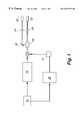
- FIG. 1is a schematic of an electro-optical laser light optical fiber switching system in accordance with an embodiment of the present invention.
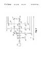
- FIG. 2is a schematic of an electro-optical laser light optical fiber switching system arranged to sequentially inject laser light into seven different optical fibers in accordance with an embodiment of the present invention.
- FIG. 3is a schematic of a laser light multiplexer arrangement in accordance with an embodiment of the present invention.
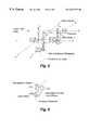
- FIG. 4is a schematic of a laser light switching system in accordance with a mechanically operated embodiment of the present invention.
- FIG. 5is a view of two waveplate positions in accordance with a mechanically operated embodiment of the present invention.
- an optical fiber switch operated by electrical activation of at least one laser light modulator paired with at least one laser light polarizeris used for the sequential injection of laser light from a single laser into a plurality of optical fibers for transport to a number of devices where it is desired to deliver a laser beam.
- the inventioncomprises an alternating series of at least one laser light modulator and at least one laser light polarizer arranged so as to direct linearly polarized laser light beams from a laser first through at least one laser light modulator.
- the laser light modulatoris intermittently activated in accordance with signals from a timing module and firing sequence controller.
- the polarization state of the light leaving the laser light modulatoris controlled by application of the voltage (or other electrical field) to the material of the laser light modulator.
- the laser light modulatorprovides the means for rotating the polarization of linearly polarized laser light entering the electro-optic laser light modulator from vertical to horizontal polarization and back.
- Pockels cellsare presently preferred as laser light modulators in the practice of the invention, Kerr cells or Faraday cells could also be used.
- the character of the electrical field and voltage useful in the inventionwill depend upon the type of laser light modulator employed.
- a voltage equivalent to the half-wave voltage for the crystal in a Pockels cellis applied to the Pockels cell. More specifically, for example, if the Pockels cell crystal is lithium niobate, approximately 3.0 kV must be applied to a laser light beam having a wavelength of 1064 nm to rotate the laser light polarization 90 degrees.
- Light from the laser light modulatoris then directed into at least one light polarizer which can accept or reject the laser light depending upon the polarization of the laser light beam arriving at the light polarizer.
- the polarizersare used as polarization dependent reflecting mirrors by analyzing the polarization state of the laser light entering the light polarizer and directing the laser light in a manner that depends upon the polarization of the light.
- the polarizermay be oriented so that vertically polarized light arriving at the light polarizer is transported through the light polarizer with no change in propagation direction while horizontally polarized light arriving at the light polarizer, on the other hand, is rejected by the light polarizer and deflected at an angle of nearly 90 degrees from its original direction by the light polarizer.
- the light polarizerthus provides the means to divert laser light from a straight-line trajectory.
- the light polarizer or polarization analyzeris controlled by the polarization altering action of the laser light modulator through which the light passes prior to entering the
- Laser light ejected from each polarizeris collected and focused onto the face of an optical fiber positioned at the focal point of a short focal length lens.
- Light injected into the optical fiberis then carried to a remote location through the length of the fiber.
- the remote locationsare the individual cylinders.
- the optical switching system of this inventioncan be used to sequentially distribute continuous wave or pulsed laser beams in a very broad range of wavelengths from about 700 nm to about 12,000 nm.
- the most useful wavelengthswill depend upon the intended application. For example, for laser ignition applications, use of laser light wavelengths in the range from about 700 nm to about 1100 nm is presently preferred if an infrared solid state laser is used.
- an 808 nm beamfrequently is used.
- Voltage as high as 2500 voltsis usually employed, with voltages in the range from about 1000 volts to about 3500 volts generally considered most useful in the practice of the invention, depending upon the size of the crystal in the Pockels cells and upon the type of electro-optic modulator crystal used.
- the voltage pulses to the laser light modulatorsmust be at least as long as the laser pulses if the laser is operated in a pulsed mode.
- lasersare suitable for use in the practice of this invention will depend upon the intended use of the laser light after transport through the plurality of optical fibers.
- suitable lasersusually include Er:YAG lasers operating at a wavelength which is readily absorbed by the fuel hydrocarbons.
- Er:YAG or Nd:YAG lasersor any other type of laser which can operate in the Q-switched, mode-locked or cavity-dumped mode can be used.
- Pockels cells useful as laser light modulators in the present inventiongenerally have crystals that exhibit the Pockels effect with ring electrodes bonded to two faces to allow application of an electrical field to the crystal.
- Crystals which can be used in the practice of this inventionare those which provide a clear aperture large enough to transmit laser light and which do not absorb at the laser wavelength. These include, but are not limited to, crystals such as lithium niobate, potassium dihydrogen phosphate, or ammonium dihydrogen phosphate. Lithium niobate crystals are generally presently preferred because these crystals have very low absorbance to laser light at visible and near infrared wavelengths and possess low half-wave voltage.
- Crystals as small as 1 mm or as large as 15 cm in cross sectioncan be used. Generally, crystal volumes in the range from about 1 mm 3 to about 10 cm 3 are most useful in the practice of the invention. Commercially available Pockels cells may be used in the invention.
- Laser light polarizers or light polarization analyzersthat are useful in the present invention are those which can analyze the polarization state of incoming laser light and direct or redirect the laser light in accordance with the polarization of the incoming laser light.
- Several useful laser light polarizersare commercially available as Glan Thompson, Glan-Laser or Thin Film Dielectric laser light polarizers.
- Glan-Laser polarizersare presently preferred because Glan-Laser polarizers are very selective to polarization state with an extinction ratio of 10 4 :1 and are highly transmissive to visible or infrared radiation.
- Lenses which are useful in the practice of this inventiongenerally are those which are of sufficiently long focal length to provide a collimated light beam or long depth of field.
- Several reflecting mirrorsare used to direct the modulator output and to redirect or to reverse the direction of light propagation through the pairs of laser light modulators and polarizers.
- FIG. 1is a schematic of an example of an optical fiber switching system in accordance with the invention for use as multiplexer of pulsed infrared laser light used to initiate the ignition of aerosol fuels in aviation combustors.
- the laser pulsesare directed to either one of the two output ports in a randomly selectable manner.
- a laser 10As shown in FIG. 1, vertically polarized light output from a laser 10 is directed into a Pockels cell 12 which functions as a laser light modulator. Voltage from a power source 14 is applied to the Pockels cell 12 so that horizontally polarized laser light is output from the Pockels cell 12 .
- a timing module 16is connected to both the laser 10 and a firing sequence controller 18 which activates the power source 14 and the Pockels cell 12 for the selected intervals.
- the horizontally polarized laser light from the Pockels cell 12is then directed into a laser light polarizer 20 , where it is either rejected (and thus directed into a light turning reflecting mirror 22 then through a first focusing lens 24 into a first optical fiber 26 ) or, if not rejected, directed through a second, or other, focusing lens 28 into a second optical fiber 30 , depending upon polarization of the light.
- An electro-optic modulator similar to the one in this embodiment but utilizing two Pockels cells and two polarization analyzers, providing 3 output channelswas demonstrated in the laboratory and was operated at switching speeds up to 30 Hz.
- laser light from a single excitation laseris sequentially injected by the optical fiber switching system into each of a plurality of optical fibers, each of which in turn transports the laser light to separate individual remotely located Nd:YAG laser fuel ignitors.
- FIG. 2shows a configuration for the invention capable of sequentially distributing laser light among each of seven optical fibers depending upon which of the Pockels cells within the system are activated at any given time by the application of a voltage.
- the embodiment of the invention shown in FIG. 2nearly doubles the number of optical fibers to which the laser light can be switched with the addition of each single Pockels cell.
- a laser 110produces a beam which is directed into a first Pockels cell 112 which functions as a laser light modulator.
- the Pockels cell 112is activated by a power source 114 a as directed by a firing sequence controller 116 which is electrically connected to two timing modules 118 and 120 .
- Each subsequent Pockels cellhas its own power supply 114 b, 114 c , . . . , the output voltage of which is controlled by the firing sequence controller 116 .
- timing modules 118 and 120permit a pulse of voltage to the Pockels cell 112 corresponding in time with the time of a laser pulse from the laser 110 , a pulse of polarized laser light is rotated by the Pockels cell 112 and directed to a light polarizer 122 . If the polarization of the initially vertically polarized laser light pulse has been rotated 90° to become horizontally polarized, it is rejected by the polarization analyzer 122 , and redirected to a light reflecting mirror 124 .
- the reflecting mirror 124is positioned so as to direct any laser light pulses it receives into a second Pockels cell 126 where the reflected laser light pulse is changed in polarization once more, and directed by way of two more reflecting mirrors 128 and 130 into a series of alternating polarizers 132 , 136 , 140 and Pockels cells 134 , 138 , and 140 .
- the laser light polarizer 122does not reject the light and transmits the pulse directly into a Pockels cell 142 aligned with and subsequent to the polarizer.
- the laser light pulses received by the subsequent Pockels cell 142are then processed in the same manner as light pulses received in the first Pockels cell 112 .
- laser lightcan be extracted from either the top or bottom (with reference to the figure) of each polarizer 122 , 132 , 136 , or 140 .
- Laser light ejected from each polarizer 122 , 132 , 136 or 140is collected and focused onto the face of an optical fiber positioned at the focal point of a short focal length lens. Light injected into the optical fiber is then carried to a remote location through the fiber length.
- the heavy arrows on the drawingdepict the path of a laser beam which is rotated 90° by the first Pockels cell 112 , redirected 90° by the first polarizer 122 into the turning mirror 124 , thence into a second Pockels cell 126 .
- the second Pockels cellwas also activated so a vertically polarized beam passed into reflecting mirrors 128 and 130 , which directed the beam unrotated through alternating polarizers 132 , 136 and Pockels cells 134 and 138 into polarizer 140 . If Pockels cell 140 were activated, the beam would be rejected and redirected 90° through a short focal length lens 144 into a fiber optic 146 that transports the beam to a remote location.
- a laser light multiplexerprovides a mechanically driven alternative to the electro-optically controlled laser light distribution system of the first described embodiments.
- the mechanically driven alternativeis substantially similar to the electro-optically controlled embodiments of the invention, except for the manner in which the light polarization changes are achieved.
- the laser beam path within the optical fiber switchis controlled by changing the laser light polarization so that the laser light will be ejected in a selected direction from one of several analyzing polarizers within the path of the laser light through the optical fiber switching system. Light ejected from the polarizer is directed through a focusing lens for injection into the selected optical fiber.
- the mechanically controlled systemuses movable halfwave plates which can be taken in and out of the laser beam path in order to change the laser light polarization at the proper point within the optical fiber switching system.
- movable halfwave plateswhich can be taken in and out of the laser beam path in order to change the laser light polarization at the proper point within the optical fiber switching system.
- the laser light polarizationis rotated by 90° so that horizontally polarized light becomes vertically polarized and vice versa.
- Another mechanical means of changing the polarizationis to simply rotate the waveplate by 90 degrees while the waveplate remains continuously within the laser beam.
- the presently preferred practiceis to insert or remove the waveplate from the laser beam by a rotary motion.
- Rotary movement of the waveplatecan be performed rapidly and can accurately reproduce the angular alignment of the waveplate with respect to the polarization of the incident laser light.
- FIG. 3The actuation of a mechanical optical fiber light switch with a six-port distribution system distributor is schematically shown in FIG. 3 .
- light from a laser 210is directed into a first polarization analyzer 212 which assures the correct polarization of the laser light (horizontal in this case, as shown by the up-down oriented arrow).
- alternating polarization analyzers and waveplatesare set up in a beam pathway.
- An embodiment using four polarization analyzers 212 , 216 , 220 and 224 ; and four waveplates 214 , 218 , 222 and 226is shown in FIG. 3 .
- Laser light from the first polarization analyzer 212is then directed past waveplate 214 into a second polarization analyzer 216 . With all waveplates being rotated out of the laser beam path except for waveplate 226 , the beam travels straight through each polarization analyzer.
- the laser lightthen takes the path through the optical switch indicated by the dark arrows.
- the polarization of the laser lightis also indicated at various points within the system.
- Light double ended arrows drawn through the dark arrowsindicate horizontal polarization.
- a dark dot through the laser light direction arrowindicates vertical polarization.
- All polarization analyzers 212 , 216 and 220transmit the horizontally polarized light.
- the laser lightis reflected by mirrors 228 , 230 and 232 so that the laser beam is finally incident upon waveplate 226 .
- Waveplate 226rotates the polarization of the laser light from horizontal to vertical.
- the laser lightis then rejected by polarization analyzers 216 and 212 so that the laser light is directed sequentially to focusing lens 234 and optic fiber 236 .
- the beamis directed into the lens 238 242 , 246 , 250 or 254 and fiber optic line 240 , 242 , 246 , 252 or 256 associated with the next polarization analyzer the beam encounters.
- FIG. 4is a schematic diagram of a mechanically actuated laser light optical switch set up to operate in accordance with another embodiment of the invention.
- the mechanically actuated laser light optical switch shown in FIG. 4is a very compact laser light optical switch.
- the three reflecting mirrors used in the embodiment shown in FIG. 3have been eliminated and the path of the light is determined strictly by the internal reflective characteristics of the polarizer cubes.
- Table Iindicates which waveplates which must be inserted within the laser beam path to provide light output to the selected optical fiber.
- FIG. 5A three-dimensional view of the embodiment of the invention shown in FIG. 4 is shown in FIG. 5 .
- the waveplatesare shown mounted in a thin (3 mm thick) rectangular holder which is attached to the shaft of a rotational solenoid.
- the rotational solenoidis used to rotate the waveplate into the laser beam path by energizing the solenoid.
- FIG. 6shows two waveplate positions.
- the angular displacement of the waveplateallows the waveplate to be either positioned within the laser beam or to be removed from the laser beam.
- a rotational solenoid 200turns the waveplate 210 into the positions according to the degree of rotation of the solenoid.
- Alignment stability for the mechanically activated optical switches of this inventionis as good as that of the electro-optical systems of this invention since axial motions of the waveplate due to mechanical play in the driving solenoid are small enough not to cause misalignments in the laser light to be injected into the optical fibers.
- switching speeds of the present inventionare limited only by the recovery time of the electro-optic crystals of the Pockels cell between polarization states. Therefore, very high switching rates as fast as 1 kHz (compared to 10 Hz in state of the art devices) can be achieved by this invention.
- the high switching rates of the inventionenable such applications as the laser ignition of multiple cylinder internal combustion engines and the multiple ignitor stabilization of combustion within turbine engine combustors.
- Other applicationsinclude use of the invention for initiation of projectile propellants for multiple barreled guns and artillery, multiple weapon arrays, artillery and communications industry technology.
Landscapes
- Physics & Mathematics (AREA)
- Nonlinear Science (AREA)
- General Physics & Mathematics (AREA)
- Optics & Photonics (AREA)
- Chemical & Material Sciences (AREA)
- Engineering & Computer Science (AREA)
- Ceramic Engineering (AREA)
- Crystallography & Structural Chemistry (AREA)
- Lasers (AREA)
Abstract
Description
| TABLE I |
| Waveplate Positions for Distribution of |
| Laser Light to Optical Fibersa |
| Output Fiber | Waveplates Inserted in Beam | ||
| 342 | b & e | ||
| 346 | a & | ||
| 350 | none | ||
| 354 | a & d | ||
| 358 | b & c | ||
| 362 | a & e | ||
| 366 | b & d | ||
| aWith reference to the schematic of FIG. 4. | |||
Claims (19)
Priority Applications (1)
| Application Number | Priority Date | Filing Date | Title |
|---|---|---|---|
| US09/259,749US6351579B1 (en) | 1998-02-27 | 1999-02-27 | Optical fiber switch |
Applications Claiming Priority (2)
| Application Number | Priority Date | Filing Date | Title |
|---|---|---|---|
| US7630198P | 1998-02-27 | 1998-02-27 | |
| US09/259,749US6351579B1 (en) | 1998-02-27 | 1999-02-27 | Optical fiber switch |
Publications (1)
| Publication Number | Publication Date |
|---|---|
| US6351579B1true US6351579B1 (en) | 2002-02-26 |
Family
ID=26757939
Family Applications (1)
| Application Number | Title | Priority Date | Filing Date |
|---|---|---|---|
| US09/259,749Expired - Fee RelatedUS6351579B1 (en) | 1998-02-27 | 1999-02-27 | Optical fiber switch |
Country Status (1)
| Country | Link |
|---|---|
| US (1) | US6351579B1 (en) |
Cited By (81)
| Publication number | Priority date | Publication date | Assignee | Title |
|---|---|---|---|---|
| US20030080650A1 (en)* | 2001-10-31 | 2003-05-01 | Wong Marvin Glenn | Longitudinal piezoelectric optical latching relay |
| US6580732B1 (en)* | 2000-07-14 | 2003-06-17 | Litton Systems, Inc. | Multiple mode laser |
| US6583645B1 (en)* | 2001-08-27 | 2003-06-24 | Xilinx, Inc. | Field programmable optical arrays |
| US20030189773A1 (en)* | 2002-03-28 | 2003-10-09 | Wong Marvin Glenn | Piezoelectric optical relay |
| US20030194170A1 (en)* | 2002-04-10 | 2003-10-16 | Wong Marvin Glenn | Piezoelectric optical demultiplexing switch |
| US20040066259A1 (en)* | 2002-10-08 | 2004-04-08 | Dove Lewis R. | Electrically isolated liquid metal micro-switches for integrally shielded microcircuits |
| US6730866B1 (en) | 2003-04-14 | 2004-05-04 | Agilent Technologies, Inc. | High-frequency, liquid metal, latching relay array |
| US6740829B1 (en) | 2003-04-14 | 2004-05-25 | Agilent Technologies, Inc. | Insertion-type liquid metal latching relay |
| US6743990B1 (en) | 2002-12-12 | 2004-06-01 | Agilent Technologies, Inc. | Volume adjustment apparatus and method for use |
| US6747222B1 (en) | 2003-02-04 | 2004-06-08 | Agilent Technologies, Inc. | Feature formation in a nonphotoimagable material and switch incorporating same |
| US6750594B2 (en) | 2002-05-02 | 2004-06-15 | Agilent Technologies, Inc. | Piezoelectrically actuated liquid metal switch |
| US6750413B1 (en) | 2003-04-25 | 2004-06-15 | Agilent Technologies, Inc. | Liquid metal micro switches using patterned thick film dielectric as channels and a thin ceramic or glass cover plate |
| US20040112729A1 (en)* | 2002-12-12 | 2004-06-17 | Wong Marvin Glenn | Switch and method for producing the same |
| US20040112728A1 (en)* | 2002-12-12 | 2004-06-17 | Wong Marvin Glenn | Ceramic channel plate for a switch |
| US20040112726A1 (en)* | 2002-12-12 | 2004-06-17 | Wong Marvin Glenn | Ultrasonically milled channel plate for a switch |
| US20040112727A1 (en)* | 2002-12-12 | 2004-06-17 | Wong Marvin Glenn | Laser cut channel plate for a switch |
| US6756551B2 (en) | 2002-05-09 | 2004-06-29 | Agilent Technologies, Inc. | Piezoelectrically actuated liquid metal switch |
| US6759611B1 (en) | 2003-06-16 | 2004-07-06 | Agilent Technologies, Inc. | Fluid-based switches and methods for producing the same |
| US6759610B1 (en) | 2003-06-05 | 2004-07-06 | Agilent Technologies, Inc. | Multi-layer assembly of stacked LIMMS devices with liquid metal vias |
| US6762378B1 (en) | 2003-04-14 | 2004-07-13 | Agilent Technologies, Inc. | Liquid metal, latching relay with face contact |
| US6765161B1 (en) | 2003-04-14 | 2004-07-20 | Agilent Technologies, Inc. | Method and structure for a slug caterpillar piezoelectric latching reflective optical relay |
| US20040140187A1 (en)* | 2003-01-22 | 2004-07-22 | Wong Marvin Glenn | Method for registering a deposited material with channel plate channels, and switch produced using same |
| US6768068B1 (en) | 2003-04-14 | 2004-07-27 | Agilent Technologies, Inc. | Method and structure for a slug pusher-mode piezoelectrically actuated liquid metal switch |
| US20040144632A1 (en)* | 2003-01-13 | 2004-07-29 | Wong Marvin Glenn | Photoimaged channel plate for a switch |
| US6770827B1 (en) | 2003-04-14 | 2004-08-03 | Agilent Technologies, Inc. | Electrical isolation of fluid-based switches |
| US6774325B1 (en) | 2003-04-14 | 2004-08-10 | Agilent Technologies, Inc. | Reducing oxides on a switching fluid in a fluid-based switch |
| US6774324B2 (en) | 2002-12-12 | 2004-08-10 | Agilent Technologies, Inc. | Switch and production thereof |
| US6777630B1 (en) | 2003-04-30 | 2004-08-17 | Agilent Technologies, Inc. | Liquid metal micro switches using as channels and heater cavities matching patterned thick film dielectric layers on opposing thin ceramic plates |
| US6781074B1 (en) | 2003-07-30 | 2004-08-24 | Agilent Technologies, Inc. | Preventing corrosion degradation in a fluid-based switch |
| US6787720B1 (en) | 2003-07-31 | 2004-09-07 | Agilent Technologies, Inc. | Gettering agent and method to prevent corrosion in a fluid switch |
| US6794591B1 (en) | 2003-04-14 | 2004-09-21 | Agilent Technologies, Inc. | Fluid-based switches |
| US6798937B1 (en) | 2003-04-14 | 2004-09-28 | Agilent Technologies, Inc. | Pressure actuated solid slug optical latching relay |
| US20040188234A1 (en)* | 2003-03-31 | 2004-09-30 | Dove Lewis R. | Hermetic seal and controlled impedance rf connections for a liquid metal micro switch |
| US6803842B1 (en) | 2003-04-14 | 2004-10-12 | Agilent Technologies, Inc. | Longitudinal mode solid slug optical latching relay |
| US20040202414A1 (en)* | 2003-04-14 | 2004-10-14 | Wong Marvin Glenn | Reflecting wedge optical wavelength multiplexer/demultiplexer |
| US20040200704A1 (en)* | 2003-04-14 | 2004-10-14 | Arthur Fong | Fluid-based switch |
| US20040202408A1 (en)* | 2003-04-14 | 2004-10-14 | Wong Marvin Glenn | Pressure actuated optical latching relay |
| US20040201907A1 (en)* | 2003-04-14 | 2004-10-14 | Wong Marvin Glenn | Liquid metal optical relay |
| US20040201322A1 (en)* | 2003-04-14 | 2004-10-14 | Wong Marvin Glenn | Longitudinal mode optical latching relay |
| US20040201447A1 (en)* | 2003-04-14 | 2004-10-14 | Wong Marvin Glenn | Thin-film resistor device |
| US20040202844A1 (en)* | 2003-04-14 | 2004-10-14 | Wong Marvin Glenn | Feature formation in thick-film inks |
| US20040201311A1 (en)* | 2003-04-14 | 2004-10-14 | Wong Marvin Glenn | High frequency bending-mode latching relay |
| US20040201320A1 (en)* | 2003-04-14 | 2004-10-14 | Carson Paul Thomas | Inserting-finger liquid metal relay |
| US20040201310A1 (en)* | 2003-04-14 | 2004-10-14 | Wong Marvin Glenn | Damped longitudinal mode optical latching relay |
| US20040200705A1 (en)* | 2003-04-14 | 2004-10-14 | Wong Marvin Glenn | Formation of signal paths to increase maximum signal-carrying frequency of a fluid-based switch |
| US20040201319A1 (en)* | 2003-04-14 | 2004-10-14 | Wong Marvin Glenn | High frequency push-mode latching relay |
| US20040201313A1 (en)* | 2003-04-14 | 2004-10-14 | Wong Marvin Glenn | High-frequency, liquid metal, latching relay with face contact |
| US20040200707A1 (en)* | 2003-04-14 | 2004-10-14 | Wong Marvin Glenn | Bent switching fluid cavity |
| US20040200706A1 (en)* | 2003-04-14 | 2004-10-14 | Dove Lewis R. | Substrate with liquid electrode |
| US20040201314A1 (en)* | 2003-04-14 | 2004-10-14 | Wong Marvin Glenn | Wetting finger latching piezoelectric relay |
| US20040202411A1 (en)* | 2003-04-14 | 2004-10-14 | Wong Marvin Glenn | Method and structure for a pusher-mode piezoelectrically actuated liquid metal optical switch |
| US20040200708A1 (en)* | 2003-04-14 | 2004-10-14 | Wong Marvin Glenn | Method and structure for a slug assisted pusher-mode piezoelectrically actuated liquid metal optical switch |
| US20040201323A1 (en)* | 2003-04-14 | 2004-10-14 | Wong Marvin Glenn | Shear mode liquid metal switch |
| US20040200702A1 (en)* | 2003-04-14 | 2004-10-14 | Arthur Fong | Push-mode latching relay |
| US20040201321A1 (en)* | 2003-04-14 | 2004-10-14 | Wong Marvin Glenn | High frequency latching relay with bending switch bar |
| US20040201315A1 (en)* | 2003-04-14 | 2004-10-14 | Wong Marvin Glenn | Bending-mode latching relay |
| US20040202558A1 (en)* | 2003-04-14 | 2004-10-14 | Arthur Fong | Closed-loop piezoelectric pump |
| US20040201318A1 (en)* | 2003-04-14 | 2004-10-14 | Wong Marvin Glen | Latching relay with switch bar |
| US20040202413A1 (en)* | 2003-04-14 | 2004-10-14 | Wong Marvin Glenn | Method and structure for a solid slug caterpillar piezoelectric optical relay |
| US20040201317A1 (en)* | 2003-04-14 | 2004-10-14 | Wong Marvin Glenn | Method and structure for a pusher-mode piezoelectrically actuated liquid switch metal switch |
| US20040201312A1 (en)* | 2003-04-14 | 2004-10-14 | Arthur Fong | Method and structure for a slug assisted longitudinal piezoelectrically actuated liquid metal optical switch |
| US20040201309A1 (en)* | 2003-04-14 | 2004-10-14 | Wong Marvin Glenn | Insertion-type liquid metal latching relay array |
| US20040201316A1 (en)* | 2003-04-14 | 2004-10-14 | Arthur Fong | Method and structure for a solid slug caterpillar piezoelectric relay |
| US20040202404A1 (en)* | 2003-04-14 | 2004-10-14 | Wong Marvin Glenn | Polymeric liquid metal optical switch |
| US20040202410A1 (en)* | 2003-04-14 | 2004-10-14 | Wong Marvin Glenn | Longitudinal electromagnetic latching optical relay |
| US20040200703A1 (en)* | 2003-04-14 | 2004-10-14 | Wong Marvin Glenn | Bending mode liquid metal switch |
| US20040201330A1 (en)* | 2003-04-14 | 2004-10-14 | Arthur Fong | Method and apparatus for maintaining a liquid metal switch in a ready-to-switch condition |
| US20040201329A1 (en)* | 2003-04-14 | 2004-10-14 | Wong Marvin Glenn | Damped longitudinal mode latching relay |
| US20040201440A1 (en)* | 2003-04-14 | 2004-10-14 | Arthur Fong | Longitudinal electromagnetic latching relay |
| US20040251117A1 (en)* | 2003-06-16 | 2004-12-16 | Wong Marvin Glenn | Suspended thin-film resistor |
| US20050034962A1 (en)* | 2003-04-14 | 2005-02-17 | Wong Marvin Glenn | Reducing oxides on a switching fluid in a fluid-based switch |
| US6927529B2 (en) | 2002-05-02 | 2005-08-09 | Agilent Technologies, Inc. | Solid slug longitudinal piezoelectric latching relay |
| US20050263379A1 (en)* | 2003-04-14 | 2005-12-01 | John Ralph Lindsey | Reduction of oxides in a fluid-based switch |
| US20080037089A1 (en)* | 2006-08-09 | 2008-02-14 | Johann Klausner | Apparatus for the distribution of laser light |
| US7845328B2 (en)* | 2006-06-20 | 2010-12-07 | Robert Bosch Gmbh | Optical distributor for a laser-based ignition system, and method for the operation thereof |
| CN103636083A (en)* | 2011-07-11 | 2014-03-12 | 株式会社V技术 | Pulse laser oscillator and method for controlling pulse laser oscillation |
| CN104900500A (en)* | 2014-03-03 | 2015-09-09 | 上海微电子装备有限公司 | Synchronous scanning laser annealing device |
| US20160276809A1 (en)* | 2015-03-16 | 2016-09-22 | Ricoh Company, Ltd. | Surface-emitting laser, surface-emitting laser array, laser apparatus, ignition device and internal combustion engine |
| US20170168412A1 (en)* | 2015-12-11 | 2017-06-15 | Ricoh Company, Ltd. | Surface-emitting laser, surface-emitting laser array, laser device, ignitor, internal combustion engine, optical scanner, image forming apparatus, light transmission module, and light emission system |
| US20170299900A1 (en)* | 2016-02-04 | 2017-10-19 | Massachusetts Institute Of Technology | Devices and Methods For Optical Spatial Mode Control |
| CN108780976A (en)* | 2016-03-21 | 2018-11-09 | 鲁美斯有限公司 | Pulse Clippers in Laser Systems |
Citations (5)
| Publication number | Priority date | Publication date | Assignee | Title |
|---|---|---|---|---|
| US3532890A (en)* | 1967-09-11 | 1970-10-06 | Bell Telephone Labor Inc | Optical multiplexing and demultiplexing systems |
| US4059759A (en)* | 1976-05-25 | 1977-11-22 | The United States Of America As Represented By The United States Energy Research And Development Administration | Passive and active pulse stacking scheme for pulse shaping |
| US4631402A (en)* | 1983-02-10 | 1986-12-23 | Hitachi, Ltd. | Optical electric-field measuring apparatus |
| US5090824A (en)* | 1990-07-31 | 1992-02-25 | Geo-Centers, Inc. | Fast optical switch having reduced light loss |
| US5197074A (en)* | 1991-12-26 | 1993-03-23 | Electro Scientific Industries, Inc. | Multi-function intra-resonator loss modulator and method of operating same |
- 1999
- 1999-02-27USUS09/259,749patent/US6351579B1/ennot_activeExpired - Fee Related
Patent Citations (5)
| Publication number | Priority date | Publication date | Assignee | Title |
|---|---|---|---|---|
| US3532890A (en)* | 1967-09-11 | 1970-10-06 | Bell Telephone Labor Inc | Optical multiplexing and demultiplexing systems |
| US4059759A (en)* | 1976-05-25 | 1977-11-22 | The United States Of America As Represented By The United States Energy Research And Development Administration | Passive and active pulse stacking scheme for pulse shaping |
| US4631402A (en)* | 1983-02-10 | 1986-12-23 | Hitachi, Ltd. | Optical electric-field measuring apparatus |
| US5090824A (en)* | 1990-07-31 | 1992-02-25 | Geo-Centers, Inc. | Fast optical switch having reduced light loss |
| US5197074A (en)* | 1991-12-26 | 1993-03-23 | Electro Scientific Industries, Inc. | Multi-function intra-resonator loss modulator and method of operating same |
Cited By (143)
| Publication number | Priority date | Publication date | Assignee | Title |
|---|---|---|---|---|
| US6580732B1 (en)* | 2000-07-14 | 2003-06-17 | Litton Systems, Inc. | Multiple mode laser |
| US6583645B1 (en)* | 2001-08-27 | 2003-06-24 | Xilinx, Inc. | Field programmable optical arrays |
| US7078849B2 (en) | 2001-10-31 | 2006-07-18 | Agilent Technologies, Inc. | Longitudinal piezoelectric optical latching relay |
| US20030080650A1 (en)* | 2001-10-31 | 2003-05-01 | Wong Marvin Glenn | Longitudinal piezoelectric optical latching relay |
| US20030189773A1 (en)* | 2002-03-28 | 2003-10-09 | Wong Marvin Glenn | Piezoelectric optical relay |
| US6741767B2 (en)* | 2002-03-28 | 2004-05-25 | Agilent Technologies, Inc. | Piezoelectric optical relay |
| US20030194170A1 (en)* | 2002-04-10 | 2003-10-16 | Wong Marvin Glenn | Piezoelectric optical demultiplexing switch |
| US6927529B2 (en) | 2002-05-02 | 2005-08-09 | Agilent Technologies, Inc. | Solid slug longitudinal piezoelectric latching relay |
| US6750594B2 (en) | 2002-05-02 | 2004-06-15 | Agilent Technologies, Inc. | Piezoelectrically actuated liquid metal switch |
| US6756551B2 (en) | 2002-05-09 | 2004-06-29 | Agilent Technologies, Inc. | Piezoelectrically actuated liquid metal switch |
| US20040066259A1 (en)* | 2002-10-08 | 2004-04-08 | Dove Lewis R. | Electrically isolated liquid metal micro-switches for integrally shielded microcircuits |
| US6781075B2 (en) | 2002-10-08 | 2004-08-24 | Agilent Technologies, Inc. | Electrically isolated liquid metal micro-switches for integrally shielded microcircuits |
| US6743990B1 (en) | 2002-12-12 | 2004-06-01 | Agilent Technologies, Inc. | Volume adjustment apparatus and method for use |
| US20050000620A1 (en)* | 2002-12-12 | 2005-01-06 | Wong Marvin Glenn | Method for making switch with ultrasonically milled channel plate |
| US20040112728A1 (en)* | 2002-12-12 | 2004-06-17 | Wong Marvin Glenn | Ceramic channel plate for a switch |
| US20040112726A1 (en)* | 2002-12-12 | 2004-06-17 | Wong Marvin Glenn | Ultrasonically milled channel plate for a switch |
| US20040112724A1 (en)* | 2002-12-12 | 2004-06-17 | Wong Marvin Glenn | Volume adjustment apparatus and method for use |
| US20040112727A1 (en)* | 2002-12-12 | 2004-06-17 | Wong Marvin Glenn | Laser cut channel plate for a switch |
| US7022926B2 (en) | 2002-12-12 | 2006-04-04 | Agilent Technologies, Inc. | Ultrasonically milled channel plate for a switch |
| US6774324B2 (en) | 2002-12-12 | 2004-08-10 | Agilent Technologies, Inc. | Switch and production thereof |
| US20050000784A1 (en)* | 2002-12-12 | 2005-01-06 | Wong Marvin Glenn | Liquid switch production and assembly |
| US6924444B2 (en) | 2002-12-12 | 2005-08-02 | Agilent Technologies, Inc. | Ceramic channel plate for a fluid-based switch, and method for making same |
| US6849144B2 (en) | 2002-12-12 | 2005-02-01 | Agilent Technologies, Inc. | Method for making switch with ultrasonically milled channel plate |
| US6855898B2 (en) | 2002-12-12 | 2005-02-15 | Agilent Technologies, Inc. | Ceramic channel plate for a switch |
| US6909059B2 (en) | 2002-12-12 | 2005-06-21 | Agilent Technologies, Inc. | Liquid switch production and assembly |
| US20040112729A1 (en)* | 2002-12-12 | 2004-06-17 | Wong Marvin Glenn | Switch and method for producing the same |
| US20050051412A1 (en)* | 2002-12-12 | 2005-03-10 | Wong Marvin Glenn | Ceramic channel plate for a fluid-based switch, and method for making same |
| US20040144632A1 (en)* | 2003-01-13 | 2004-07-29 | Wong Marvin Glenn | Photoimaged channel plate for a switch |
| US6897387B2 (en) | 2003-01-13 | 2005-05-24 | Agilent Technologies, Inc. | Photoimaged channel plate for a switch |
| US20050126899A1 (en)* | 2003-01-13 | 2005-06-16 | Wong Marvin G. | Photoimaged channel plate for a switch, and method for making a switch using same |
| US7098413B2 (en) | 2003-01-13 | 2006-08-29 | Agilent Technologies, Inc. | Photoimaged channel plate for a switch, and method for making a switch using same |
| US7019235B2 (en) | 2003-01-13 | 2006-03-28 | Agilent Technologies, Inc. | Photoimaged channel plate for a switch |
| US20040140187A1 (en)* | 2003-01-22 | 2004-07-22 | Wong Marvin Glenn | Method for registering a deposited material with channel plate channels, and switch produced using same |
| US6911611B2 (en) | 2003-01-22 | 2005-06-28 | Agilent Technologies, Inc. | Method for registering a deposited material with channel plate channels |
| US6809277B2 (en) | 2003-01-22 | 2004-10-26 | Agilent Technologies, Inc. | Method for registering a deposited material with channel plate channels, and switch produced using same |
| US6747222B1 (en) | 2003-02-04 | 2004-06-08 | Agilent Technologies, Inc. | Feature formation in a nonphotoimagable material and switch incorporating same |
| US20040188234A1 (en)* | 2003-03-31 | 2004-09-30 | Dove Lewis R. | Hermetic seal and controlled impedance rf connections for a liquid metal micro switch |
| US6825429B2 (en) | 2003-03-31 | 2004-11-30 | Agilent Technologies, Inc. | Hermetic seal and controlled impedance RF connections for a liquid metal micro switch |
| US20040200703A1 (en)* | 2003-04-14 | 2004-10-14 | Wong Marvin Glenn | Bending mode liquid metal switch |
| US6872904B2 (en) | 2003-04-14 | 2005-03-29 | Agilent Technologies, Inc. | Fluid-based switch |
| US20040201907A1 (en)* | 2003-04-14 | 2004-10-14 | Wong Marvin Glenn | Liquid metal optical relay |
| US20040201322A1 (en)* | 2003-04-14 | 2004-10-14 | Wong Marvin Glenn | Longitudinal mode optical latching relay |
| US20040201447A1 (en)* | 2003-04-14 | 2004-10-14 | Wong Marvin Glenn | Thin-film resistor device |
| US20040202844A1 (en)* | 2003-04-14 | 2004-10-14 | Wong Marvin Glenn | Feature formation in thick-film inks |
| US20040201311A1 (en)* | 2003-04-14 | 2004-10-14 | Wong Marvin Glenn | High frequency bending-mode latching relay |
| US20040201320A1 (en)* | 2003-04-14 | 2004-10-14 | Carson Paul Thomas | Inserting-finger liquid metal relay |
| US20040201310A1 (en)* | 2003-04-14 | 2004-10-14 | Wong Marvin Glenn | Damped longitudinal mode optical latching relay |
| US20040200705A1 (en)* | 2003-04-14 | 2004-10-14 | Wong Marvin Glenn | Formation of signal paths to increase maximum signal-carrying frequency of a fluid-based switch |
| US20040201319A1 (en)* | 2003-04-14 | 2004-10-14 | Wong Marvin Glenn | High frequency push-mode latching relay |
| US20040201313A1 (en)* | 2003-04-14 | 2004-10-14 | Wong Marvin Glenn | High-frequency, liquid metal, latching relay with face contact |
| US20040200707A1 (en)* | 2003-04-14 | 2004-10-14 | Wong Marvin Glenn | Bent switching fluid cavity |
| US20040200706A1 (en)* | 2003-04-14 | 2004-10-14 | Dove Lewis R. | Substrate with liquid electrode |
| US20040201314A1 (en)* | 2003-04-14 | 2004-10-14 | Wong Marvin Glenn | Wetting finger latching piezoelectric relay |
| US20040202411A1 (en)* | 2003-04-14 | 2004-10-14 | Wong Marvin Glenn | Method and structure for a pusher-mode piezoelectrically actuated liquid metal optical switch |
| US20040200708A1 (en)* | 2003-04-14 | 2004-10-14 | Wong Marvin Glenn | Method and structure for a slug assisted pusher-mode piezoelectrically actuated liquid metal optical switch |
| US20040201323A1 (en)* | 2003-04-14 | 2004-10-14 | Wong Marvin Glenn | Shear mode liquid metal switch |
| US20040200702A1 (en)* | 2003-04-14 | 2004-10-14 | Arthur Fong | Push-mode latching relay |
| US20040201321A1 (en)* | 2003-04-14 | 2004-10-14 | Wong Marvin Glenn | High frequency latching relay with bending switch bar |
| US20040201315A1 (en)* | 2003-04-14 | 2004-10-14 | Wong Marvin Glenn | Bending-mode latching relay |
| US20040202558A1 (en)* | 2003-04-14 | 2004-10-14 | Arthur Fong | Closed-loop piezoelectric pump |
| US20040201318A1 (en)* | 2003-04-14 | 2004-10-14 | Wong Marvin Glen | Latching relay with switch bar |
| US20040201906A1 (en)* | 2003-04-14 | 2004-10-14 | Wong Marvin Glenn | Longitudinal mode solid slug optical latching relay |
| US20040202412A1 (en)* | 2003-04-14 | 2004-10-14 | Wong Marvin Glenn | Pressure actuated solid slug optical latching relay |
| US20040202413A1 (en)* | 2003-04-14 | 2004-10-14 | Wong Marvin Glenn | Method and structure for a solid slug caterpillar piezoelectric optical relay |
| US20040201317A1 (en)* | 2003-04-14 | 2004-10-14 | Wong Marvin Glenn | Method and structure for a pusher-mode piezoelectrically actuated liquid switch metal switch |
| US20040201312A1 (en)* | 2003-04-14 | 2004-10-14 | Arthur Fong | Method and structure for a slug assisted longitudinal piezoelectrically actuated liquid metal optical switch |
| US20040201309A1 (en)* | 2003-04-14 | 2004-10-14 | Wong Marvin Glenn | Insertion-type liquid metal latching relay array |
| US20040201316A1 (en)* | 2003-04-14 | 2004-10-14 | Arthur Fong | Method and structure for a solid slug caterpillar piezoelectric relay |
| US20040202404A1 (en)* | 2003-04-14 | 2004-10-14 | Wong Marvin Glenn | Polymeric liquid metal optical switch |
| US20040202410A1 (en)* | 2003-04-14 | 2004-10-14 | Wong Marvin Glenn | Longitudinal electromagnetic latching optical relay |
| US20040200704A1 (en)* | 2003-04-14 | 2004-10-14 | Arthur Fong | Fluid-based switch |
| US20040201330A1 (en)* | 2003-04-14 | 2004-10-14 | Arthur Fong | Method and apparatus for maintaining a liquid metal switch in a ready-to-switch condition |
| US20040201329A1 (en)* | 2003-04-14 | 2004-10-14 | Wong Marvin Glenn | Damped longitudinal mode latching relay |
| US20040201440A1 (en)* | 2003-04-14 | 2004-10-14 | Arthur Fong | Longitudinal electromagnetic latching relay |
| US20040202414A1 (en)* | 2003-04-14 | 2004-10-14 | Wong Marvin Glenn | Reflecting wedge optical wavelength multiplexer/demultiplexer |
| US6816641B2 (en) | 2003-04-14 | 2004-11-09 | Agilent Technologies, Inc. | Method and structure for a solid slug caterpillar piezoelectric optical relay |
| US6818844B2 (en) | 2003-04-14 | 2004-11-16 | Agilent Technologies, Inc. | Method and structure for a slug assisted pusher-mode piezoelectrically actuated liquid metal optical switch |
| US6803842B1 (en) | 2003-04-14 | 2004-10-12 | Agilent Technologies, Inc. | Longitudinal mode solid slug optical latching relay |
| US6831532B2 (en) | 2003-04-14 | 2004-12-14 | Agilent Technologies, Inc. | Push-mode latching relay |
| US6730866B1 (en) | 2003-04-14 | 2004-05-04 | Agilent Technologies, Inc. | High-frequency, liquid metal, latching relay array |
| US6740829B1 (en) | 2003-04-14 | 2004-05-25 | Agilent Technologies, Inc. | Insertion-type liquid metal latching relay |
| US6838959B2 (en) | 2003-04-14 | 2005-01-04 | Agilent Technologies, Inc. | Longitudinal electromagnetic latching relay |
| US6798937B1 (en) | 2003-04-14 | 2004-09-28 | Agilent Technologies, Inc. | Pressure actuated solid slug optical latching relay |
| US6794591B1 (en) | 2003-04-14 | 2004-09-21 | Agilent Technologies, Inc. | Fluid-based switches |
| US6841746B2 (en) | 2003-04-14 | 2005-01-11 | Agilent Technologies, Inc. | Bent switching fluid cavity |
| US7070908B2 (en) | 2003-04-14 | 2006-07-04 | Agilent Technologies, Inc. | Feature formation in thick-film inks |
| US7071432B2 (en) | 2003-04-14 | 2006-07-04 | Agilent Technologies, Inc. | Reduction of oxides in a fluid-based switch |
| US20050034962A1 (en)* | 2003-04-14 | 2005-02-17 | Wong Marvin Glenn | Reducing oxides on a switching fluid in a fluid-based switch |
| US20050034963A1 (en)* | 2003-04-14 | 2005-02-17 | Arthur Fong | Fluid-based switch |
| US7048519B2 (en) | 2003-04-14 | 2006-05-23 | Agilent Technologies, Inc. | Closed-loop piezoelectric pump |
| US6870111B2 (en) | 2003-04-14 | 2005-03-22 | Agilent Technologies, Inc. | Bending mode liquid metal switch |
| US20040202408A1 (en)* | 2003-04-14 | 2004-10-14 | Wong Marvin Glenn | Pressure actuated optical latching relay |
| US6876132B2 (en) | 2003-04-14 | 2005-04-05 | Agilent Technologies, Inc. | Method and structure for a solid slug caterpillar piezoelectric relay |
| US6876131B2 (en) | 2003-04-14 | 2005-04-05 | Agilent Technologies, Inc. | High-frequency, liquid metal, latching relay with face contact |
| US6876133B2 (en) | 2003-04-14 | 2005-04-05 | Agilent Technologies, Inc. | Latching relay with switch bar |
| US6879089B2 (en) | 2003-04-14 | 2005-04-12 | Agilent Technologies, Inc. | Damped longitudinal mode optical latching relay |
| US6879088B2 (en) | 2003-04-14 | 2005-04-12 | Agilent Technologies, Inc. | Insertion-type liquid metal latching relay array |
| US6882088B2 (en) | 2003-04-14 | 2005-04-19 | Agilent Technologies, Inc. | Bending-mode latching relay |
| US6885133B2 (en) | 2003-04-14 | 2005-04-26 | Agilent Technologies, Inc. | High frequency bending-mode latching relay |
| US6888977B2 (en) | 2003-04-14 | 2005-05-03 | Agilent Technologies, Inc. | Polymeric liquid metal optical switch |
| US6891315B2 (en) | 2003-04-14 | 2005-05-10 | Agilent Technologies, Inc. | Shear mode liquid metal switch |
| US6891116B2 (en) | 2003-04-14 | 2005-05-10 | Agilent Technologies, Inc. | Substrate with liquid electrode |
| US6894424B2 (en) | 2003-04-14 | 2005-05-17 | Agilent Technologies, Inc. | High frequency push-mode latching relay |
| US6894237B2 (en) | 2003-04-14 | 2005-05-17 | Agilent Technologies, Inc. | Formation of signal paths to increase maximum signal-carrying frequency of a fluid-based switch |
| US6774325B1 (en) | 2003-04-14 | 2004-08-10 | Agilent Technologies, Inc. | Reducing oxides on a switching fluid in a fluid-based switch |
| US6900578B2 (en) | 2003-04-14 | 2005-05-31 | Agilent Technologies, Inc. | High frequency latching relay with bending switch bar |
| US6903492B2 (en) | 2003-04-14 | 2005-06-07 | Agilent Technologies, Inc. | Wetting finger latching piezoelectric relay |
| US6903287B2 (en) | 2003-04-14 | 2005-06-07 | Agilent Technologies, Inc. | Liquid metal optical relay |
| US6903490B2 (en) | 2003-04-14 | 2005-06-07 | Agilent Technologies, Inc. | Longitudinal mode optical latching relay |
| US6903493B2 (en) | 2003-04-14 | 2005-06-07 | Agilent Technologies, Inc. | Inserting-finger liquid metal relay |
| US6906271B2 (en) | 2003-04-14 | 2005-06-14 | Agilent Technologies, Inc. | Fluid-based switch |
| US6770827B1 (en) | 2003-04-14 | 2004-08-03 | Agilent Technologies, Inc. | Electrical isolation of fluid-based switches |
| US6768068B1 (en) | 2003-04-14 | 2004-07-27 | Agilent Technologies, Inc. | Method and structure for a slug pusher-mode piezoelectrically actuated liquid metal switch |
| US6765161B1 (en) | 2003-04-14 | 2004-07-20 | Agilent Technologies, Inc. | Method and structure for a slug caterpillar piezoelectric latching reflective optical relay |
| US6920259B2 (en) | 2003-04-14 | 2005-07-19 | Agilent Technologies, Inc. | Longitudinal electromagnetic latching optical relay |
| US6762378B1 (en) | 2003-04-14 | 2004-07-13 | Agilent Technologies, Inc. | Liquid metal, latching relay with face contact |
| US6924443B2 (en) | 2003-04-14 | 2005-08-02 | Agilent Technologies, Inc. | Reducing oxides on a switching fluid in a fluid-based switch |
| US6925223B2 (en) | 2003-04-14 | 2005-08-02 | Agilent Technologies, Inc. | Pressure actuated optical latching relay |
| US7012354B2 (en) | 2003-04-14 | 2006-03-14 | Agilent Technologies, Inc. | Method and structure for a pusher-mode piezoelectrically actuated liquid metal switch |
| US6956990B2 (en) | 2003-04-14 | 2005-10-18 | Agilent Technologies, Inc. | Reflecting wedge optical wavelength multiplexer/demultiplexer |
| US6961487B2 (en) | 2003-04-14 | 2005-11-01 | Agilent Technologies, Inc. | Method and structure for a pusher-mode piezoelectrically actuated liquid metal optical switch |
| US20050263379A1 (en)* | 2003-04-14 | 2005-12-01 | John Ralph Lindsey | Reduction of oxides in a fluid-based switch |
| US6750413B1 (en) | 2003-04-25 | 2004-06-15 | Agilent Technologies, Inc. | Liquid metal micro switches using patterned thick film dielectric as channels and a thin ceramic or glass cover plate |
| US6777630B1 (en) | 2003-04-30 | 2004-08-17 | Agilent Technologies, Inc. | Liquid metal micro switches using as channels and heater cavities matching patterned thick film dielectric layers on opposing thin ceramic plates |
| US6759610B1 (en) | 2003-06-05 | 2004-07-06 | Agilent Technologies, Inc. | Multi-layer assembly of stacked LIMMS devices with liquid metal vias |
| US6759611B1 (en) | 2003-06-16 | 2004-07-06 | Agilent Technologies, Inc. | Fluid-based switches and methods for producing the same |
| US6833520B1 (en) | 2003-06-16 | 2004-12-21 | Agilent Technologies, Inc. | Suspended thin-film resistor |
| US20040251117A1 (en)* | 2003-06-16 | 2004-12-16 | Wong Marvin Glenn | Suspended thin-film resistor |
| US6781074B1 (en) | 2003-07-30 | 2004-08-24 | Agilent Technologies, Inc. | Preventing corrosion degradation in a fluid-based switch |
| US6787720B1 (en) | 2003-07-31 | 2004-09-07 | Agilent Technologies, Inc. | Gettering agent and method to prevent corrosion in a fluid switch |
| US7845328B2 (en)* | 2006-06-20 | 2010-12-07 | Robert Bosch Gmbh | Optical distributor for a laser-based ignition system, and method for the operation thereof |
| US20080037089A1 (en)* | 2006-08-09 | 2008-02-14 | Johann Klausner | Apparatus for the distribution of laser light |
| CN103636083A (en)* | 2011-07-11 | 2014-03-12 | 株式会社V技术 | Pulse laser oscillator and method for controlling pulse laser oscillation |
| US20140126591A1 (en)* | 2011-07-11 | 2014-05-08 | V Technology Co., Ltd. | Pulsed laser oscillator and method for controlling pulsed laser oscillation |
| US9054494B2 (en)* | 2011-07-11 | 2015-06-09 | V Technology Co., Ltd. | Pulsed laser oscillator and method for controlling pulsed laser oscillation |
| CN104900500A (en)* | 2014-03-03 | 2015-09-09 | 上海微电子装备有限公司 | Synchronous scanning laser annealing device |
| CN104900500B (en)* | 2014-03-03 | 2018-08-14 | 上海微电子装备(集团)股份有限公司 | A kind of synchronous scanning laser anneal device |
| US20160276809A1 (en)* | 2015-03-16 | 2016-09-22 | Ricoh Company, Ltd. | Surface-emitting laser, surface-emitting laser array, laser apparatus, ignition device and internal combustion engine |
| US20170168412A1 (en)* | 2015-12-11 | 2017-06-15 | Ricoh Company, Ltd. | Surface-emitting laser, surface-emitting laser array, laser device, ignitor, internal combustion engine, optical scanner, image forming apparatus, light transmission module, and light emission system |
| US10054870B2 (en)* | 2015-12-11 | 2018-08-21 | Ricoh Company, Ltd. | Surface-emitting laser, surface-emitting laser array, laser device, ignitor, internal combustion engine, optical scanner, image forming apparatus, light transmission module, and light emission system |
| US20170299900A1 (en)* | 2016-02-04 | 2017-10-19 | Massachusetts Institute Of Technology | Devices and Methods For Optical Spatial Mode Control |
| US10901240B2 (en)* | 2016-02-04 | 2021-01-26 | Massachusetts Institute Of Technology | Electro-Optic beam controller and method |
| CN108780976A (en)* | 2016-03-21 | 2018-11-09 | 鲁美斯有限公司 | Pulse Clippers in Laser Systems |
Similar Documents
| Publication | Publication Date | Title |
|---|---|---|
| US6351579B1 (en) | Optical fiber switch | |
| US4331387A (en) | Electro-optical modulator for randomly polarized light | |
| US6394788B1 (en) | Laser ignition | |
| US6676402B1 (en) | Laser ignition | |
| US4989941A (en) | Normal incidence optical switches using ferroelectric liquid crystals | |
| US4948229A (en) | Optical switches using ferroelectric liquid crystals | |
| EP0108773B1 (en) | Agile beam laser | |
| US4441186A (en) | Electronically switchable multiwavelength laser system | |
| EP1939665B1 (en) | Laser microscope and control method for the same | |
| US4796263A (en) | FTIR optical manifold and wavelength agile laser system | |
| US5319477A (en) | Compact polarization independent optical switching units | |
| KR102665093B1 (en) | Optics and method for providing two offset laser beams | |
| US2909972A (en) | Display apparatus employing electro-optical devices | |
| JPH02294088A (en) | Power laser generator | |
| CN110646959B (en) | Reflective circulator | |
| US4998259A (en) | Gatling gun laser pulse amplifier using rotating mirrors | |
| US4989216A (en) | Double conjugate laser amplifier | |
| SE8800340L (en) | LASER RADIATING SYSTEM | |
| WO2001069136A1 (en) | Laser ignition | |
| US20050174639A1 (en) | Fast all-optical switches and attenuators | |
| CN210090832U (en) | Laser beam splitting and independent output control device | |
| US3485553A (en) | Electro-optic light beam deflector | |
| US5568286A (en) | Fast liquid crystal switching unit | |
| JP2001510907A (en) | Apparatus and method for electrical control of unpolarized light intensity | |
| US20100188723A1 (en) | Optical modulator with beam-pointing correction |
Legal Events
| Date | Code | Title | Description |
|---|---|---|---|
| AS | Assignment | Owner name:REGENTS OF THE UNIVERSITY OF CALIFORNIA, THE, NEW Free format text:ASSIGNMENT OF ASSIGNORS INTEREST;ASSIGNOR:EARLY, JAMES W.;REEL/FRAME:009801/0321 Effective date:19990226 | |
| AS | Assignment | Owner name:CALIFORNIA, UNIVERSITY OF, REGENTS OF, THE, NEW ME Free format text:ASSIGNMENT OF ASSIGNORS INTEREST;ASSIGNORS:EARLY, JAMES W.;LESTER, CHARLES;REEL/FRAME:009889/0725 Effective date:19990309 Owner name:REGENTS OF THE UNIVERSITY OF CALIFORNIA, THE, NEW Free format text:ASSIGNMENT OF ASSIGNORS INTEREST;ASSIGNORS:EARLY, JAMES W.;LESTER, CHARLES;REEL/FRAME:009889/0725 Effective date:19990309 | |
| AS | Assignment | Owner name:ENERGY, U.S. DEPARTMENT OF, DISTRICT OF COLUMBIA Free format text:CONFIRMATORY LICENSE;ASSIGNOR:CALIFORNIA, UNIVERSITY OF;REEL/FRAME:012849/0768 Effective date:19990526 | |
| REMI | Maintenance fee reminder mailed | ||
| FEPP | Fee payment procedure | Free format text:PAT HOLDER CLAIMS SMALL ENTITY STATUS, ENTITY STATUS SET TO SMALL (ORIGINAL EVENT CODE: LTOS); ENTITY STATUS OF PATENT OWNER: SMALL ENTITY | |
| FPAY | Fee payment | Year of fee payment:4 | |
| SULP | Surcharge for late payment | ||
| AS | Assignment | Owner name:LOS ALAMOS NATIONAL SECURITY, LLC, NEW MEXICO Free format text:ASSIGNMENT OF ASSIGNORS INTEREST;ASSIGNOR:REGENTS OF THE UNIVERSITY OF CALIFORNIA, THE;REEL/FRAME:017914/0535 Effective date:20060515 | |
| REMI | Maintenance fee reminder mailed | ||
| LAPS | Lapse for failure to pay maintenance fees | ||
| STCH | Information on status: patent discontinuation | Free format text:PATENT EXPIRED DUE TO NONPAYMENT OF MAINTENANCE FEES UNDER 37 CFR 1.362 | |
| FP | Lapsed due to failure to pay maintenance fee | Effective date:20100226 |