US6351529B1 - Method and system for automatic gain control with adaptive table lookup - Google Patents
Method and system for automatic gain control with adaptive table lookupDownload PDFInfo
- Publication number
- US6351529B1 US6351529B1US09/067,144US6714498AUS6351529B1US 6351529 B1US6351529 B1US 6351529B1US 6714498 AUS6714498 AUS 6714498AUS 6351529 B1US6351529 B1US 6351529B1
- Authority
- US
- United States
- Prior art keywords
- gain
- signal
- power
- lookup table
- agc
- Prior art date
- Legal status (The legal status is an assumption and is not a legal conclusion. Google has not performed a legal analysis and makes no representation as to the accuracy of the status listed.)
- Expired - Fee Related
Links
Images


Classifications
- H—ELECTRICITY
- H04—ELECTRIC COMMUNICATION TECHNIQUE
- H04M—TELEPHONIC COMMUNICATION
- H04M1/00—Substation equipment, e.g. for use by subscribers
- H04M1/60—Substation equipment, e.g. for use by subscribers including speech amplifiers
- H04M1/6033—Substation equipment, e.g. for use by subscribers including speech amplifiers for providing handsfree use or a loudspeaker mode in telephone sets
- H—ELECTRICITY
- H03—ELECTRONIC CIRCUITRY
- H03G—CONTROL OF AMPLIFICATION
- H03G3/00—Gain control in amplifiers or frequency changers
- H03G3/20—Automatic control
- H03G3/30—Automatic control in amplifiers having semiconductor devices
- H03G3/3089—Control of digital or coded signals
- H—ELECTRICITY
- H04—ELECTRIC COMMUNICATION TECHNIQUE
- H04M—TELEPHONIC COMMUNICATION
- H04M1/00—Substation equipment, e.g. for use by subscribers
- H04M1/60—Substation equipment, e.g. for use by subscribers including speech amplifiers
- H04M1/6008—Substation equipment, e.g. for use by subscribers including speech amplifiers in the transmitter circuit
- H—ELECTRICITY
- H04—ELECTRIC COMMUNICATION TECHNIQUE
- H04M—TELEPHONIC COMMUNICATION
- H04M1/00—Substation equipment, e.g. for use by subscribers
- H04M1/60—Substation equipment, e.g. for use by subscribers including speech amplifiers
- H04M1/6016—Substation equipment, e.g. for use by subscribers including speech amplifiers in the receiver circuit
Definitions
- This inventionrelates to automatic gain controls (“AGC”). More specifically, it relates to a method and system for implementing an AGC using a lookup table, and an AGC having the ability to adaptively maintain a desired amplitude output signal.
- AGCautomatic gain controls
- speakerphonesOne problem associated with speakerphones is that the people involved in the conversation will most likely be different distances from the microphone that receives their voices. As a result, the volume of the different speaker's voices will vary with their distance from the microphone. For example, the volume of speakers physically situated near the microphone tends to be loud, while other speakers are barely audible. Simply amplifying the microphone so that the lowest volume speakers can be heard may result in other speaker's voices being over-amplified. This effect can be very distracting, making it difficult to listen and understand the conversation.
- AGCautomatic gain control circuits
- AGC circuitscan be used to automatically vary the amplification of different speaker's voices to equalize their relative volumes.
- AGC circuitryis typically employed to maintain a constant amplification gain for electronic circuitry that may otherwise vary over time.
- the gain of an electronic circuitmay change over time, varying with several factors such as the amplitude or frequency of the input signal, the ambient temperature, as well as other external and internal factors.
- a conventional digital AGC implementationutilizes a linear negative feedback loop.
- the AGC circuitryamplifies an input signal to provide an output signal level.
- the AGC circuitryvaries the amplification gain to provide the desired output signal level.
- the output signal levelis compared to a desired reference signal level and an error signal computed as the difference between the output signal level and the desired reference signal level.
- the error signalis fed back to adjust the amplification gain such that the output signal level matches the desired reference signal level.
- amplification gain adjustmentsare made proportional to the error signal computed with respect to an estimate of the output power.
- the output poweris determined as an exponentially weighed average over a time constant.
- This conventional type of AGC feedback systemdoes not handle voice signals particularly well because it must deal with transitions from a period of significant signal level, such as a voice signal, to a non-signal, such as a period of silence after the transition has already occurred.
- This conventional systemassumes the input is statistically constant, or in other words, wide-sense stationary.
- An actual voice signalis not constant but varies widely during speech as well as in between periods of speech and non-speech.
- An automatic gain control employing only feedback compensationmay therefore cause the boundaries between intervals of speech and non-speech to become blurred.
- the present inventionprovides an AGC system that can be utilized for equalizing the amplification gain of a speakerphone microphone.
- an open loop AGC with an amplification gain lookup table to store the appropriate amplification gain valuesis described.
- the illustrative embodimentincludes a power level estimator, the amplification gain lookup table, and a multiplier.
- the power level estimatorestimates the power level of the input signal and the AGC system selects the appropriate amplification gain from the amplification gain lookup table as a function of the input signal power.
- the multipliermultiplies the input signal by the amplification gain to provide an AGC output signal.
- the amplification gain lookup tablehas a gain transfer function providing good signal amplitude control.
- the appropriate gain valuemay be calculated as a direct function evaluation.
- the non-signal/signal input conditionis detected before application of the gain lookup table.
- a method for providing automatic gain controlincludes the steps of estimating the power of the signal, generating a gain value in accordance with the power of the signal, and applying the gain value to the signal to form the automatic gain control signal.
- a closed loop AGCwith the ability to adapt to the particular characteristics of the input signal.
- the closed loop AGCmay learn and compensate for the non-linearity of the AGC system.
- An illustrative embodimentincludes an AGC system, an AGC output power estimation block, an adder and a gain lookup table.
- the AGC output power estimation blockestimates the output power of the AGC system.
- the addercompares the AGC output power to an amplitude set-point. The difference between the amplitude set-point and the AGC output power is computed as an error signal.
- the error signalmay be scaled by a factor and used to update the gain values in the lookup table.
- the output signal of the AGC systemis used to adapt the amplification gain lookup table to compensate for the particularities of the input signal and the system is adapted as it operates.
- a method of providing an adaptive AGCis described.
- the exemplary methodallows the non-linearity of the system to be learned and compensated.
- executable software code and a computer system with memoryis used to implement the AGC system.
- dedicated hardwareis used to implement the AGC system.
- the illustrative embodimentprovides an AGC system providing good amplitude gain control.
- the amplification gain tableallows the gain level to be selected in a non-linear fashion to provide the most appropriate gain level.
- the amplification gain tailorcan also be dynamically modified and adapted to compensate for the non-linearity of the system. By combining feed-forward and feedback compensation, the described embodiment can reduce the distortion of speech caused by conventional feedback-only AGC systems.
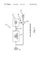
- FIG. 1shows a block diagram illustrating an open loop embodiment of the present invention
- FIG. 2illustrates a transfer function of a gain lookup table providing good signal amplification used in the system of FIG. 1;
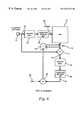
- FIG. 3shows a block diagram illustrating a closed loop embodiment of the present invention
- FIG. 4shows a flow chart illustrating a method in accordance with the closed loop embodiment of FIG. 3;
- FIG. 5shows a block diagram illustrating a computer processor based embodiment of the present invention
- FIG. 6shows a block diagram illustrating a hardware embodiment of the present invention.
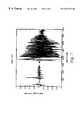
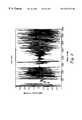
- FIGS. 7 and 8show diagrams of signals before and after application of the AGC.
- FIG. 1is a block diagram of an illustrative embodiment of the invention describing an open loop AGC system.
- the input sample signal ne(t) 12is fed to an input power estimation block 14 to estimate the power P in (t) 16 of the input signal 12 .
- the input sample signal ne(t) 12is typically a digitally sampled voice signal provided from a microphone and voice codec combination.
- the microphonereceives the speaker(s) voices and the voice codec preferably converts the analog microphone signal to a digitally sampled pulse code modulated (“PCM”) signal.
- PCMpulse code modulated
- mu-law compandingconverts the analog signal into an 8-bit sample at 8000 samples per second into a 64 kilobit per second digital signal.
- the estimated power P in (t) 16is preferably formed over a particular duration of time, as determined by the power estimation or AGC time constant.
- the input power estimation block 14preferably estimates the signal power P in (t) 16 of the input sample signal 12 using a single pole filter of the form:
- Alpha ( ⁇ )determines the AGC time constant. The smaller the value of alpha, the larger the time constant, and consequentially a greater degree of signal amplitude fluctuations is permitted.
- other methods for estimating the input signal powersuch as replacing the absolute value operation by a squaring operation, may be used.
- the estimated power P in (t) 16 of the input sample signal ne(t) 12is then used to form an address to access the gain lookup table 18 to obtain the appropriate amplification gain value g(t) 20 as a function of the input signal, as will be described in more detail.
- the gain lookup table 18provides a plurality of gain values that can be applied to the input signal.
- FIG. 2shows an exemplary transfer function of a gain lookup table 18 containing amplification gain values that provide good signal amplitude control.
- the gain lookup table 18if the input sample signal ne(t) 12 level is either below a noise level, THQUIET, or above a saturation level, THSAT, the gain lookup table 18 provides a fixed gain value, GHI and GSAT respectively. In-between the THQUIET and THSAT levels, the gain values can be selected by the following exemplary function:
- the negative exponential function for calculating the gain level g(t)provides a good approximation to the inverse transfer characteristics of the microphone-codec combination. Due to effects of saturation, as the input signal nears its maximal value, the output signal will asymptotically approach a constant value. One minus a negative exponential is a good model of this behavior. One possible inverse function is then the negative exponential.
- the calculated gain values g(t)are stored at the appropriate address locations in the gain lookup table 18 .
- the gain lookup table 18is preferably a computer data structure such as an addressable data array stored in computer memory.
- the input signal power P in (t) 16is used to form an address accessing the gain lookup table 18 to index and retrieve the appropriate gain setting. Accordingly, the appropriate gain value g(t) 20 is selected as a function of the power of the input signal.
- the result of the function evaluationcan be rounded and the high 16-bits cast to an unsigned integer.
- the resulting 16-bit integeris an index into the gain table.
- the indexmay be added to a base address, such as the address of the gain table in memory, to form a memory address.
- the functionprovides a linear index into the gain table for input power estimates greater then the quiet level. Due to the finite precision of the arithmetic, input power levels are truncated to the nearest table entry.
- the gain lookup table 18is preferably implemented to be smaller than the total possible range of gain values. Interpolation between points may be used to derive points not in stored in the gain lookup table, but is not required. Alternately, some form of interpolation, either linear, polynomial, or with spines, could be used to give gain values lying in between the actual table entries.
- direct function evaluationcan be employed as an alternative to the gain lookup table 18 .
- the function corresponding to the desired gain tablecan be evaluated at the value of the estimated input signal sample power P in (t) 16 to calculate the appropriate gain setting g(t) 20 .
- the function evaluationis performed by programming the function with computer software running on a computer processor. This alternate embodiment may require additional computing power to evaluate the function, but may save on the amount of computer memory otherwise occupied by the gain lookup table 12 and any memory access latency delay in accessing the memory table.
- Each amplification gain value g(t) 20 extracted from the gain lookup table 18is then applied to the original input sample signal ne(t) 12 value to produce the AGC controlled output sample value 24 .
- a multiplier 22can be used to multiply the input sample 12 by the gain value 20 to form the AGC output.
- the gain slope set by the constant bcan be chosen empirically according to the operating characteristics of the system, the choice of parameter values, GHI, GSAT, GNOISE, THQUIET, and THSAT.
- FIG. 3shows an exemplary closed loop embodiment of the table driven AGC with the ability to adapt the gain lookup table 18 (FIG. 1 ).
- the gain lookup table 18is dynamically adapted according to the input sample signal ne(t) 12 and the AGC output sample value 24 .
- the gain lookup table 18is adapted as the AGC system operates on input sample signal ne(t) 12 .
- the non-linearity of the systemtypically the non-linear conversion of the voice codec in the speakerphone example, is learned and the gain lookup table 18 dynamically adapted to compensate for any non-linearity of the AGC system.
- lookup table adaptation and AGC signal controlcan occur simultaneously.
- the exemplary closed loop embodimentincludes an AGC system such as the open loop embodiment 10 shown in FIG. 1 .
- the AGC output sample value 24 of FIG. 1is supplied to an output power block 26 .
- the output power block 26determines the output power of the of the output sample value 24 .
- the output power block 26is an power estimation block which estimates the output power P out (t) 28 of the output sample value 24 in the same manner as which the input power estimation block 14 (FIG. 1) estimates the power of the input sample signal 12 .
- a single pole filter and the identical time constantare used.
- the estimated output power 28is used to adapt the gain lookup table 18 according to the actual non-linearity of the AGC system 10 .
- the entries of the gain lookup table 18are then adapted based on the estimated output power 28 according to the following exemplary function:
- An error signal 34is determined using adder 30 .
- the error signal 34is calculated from the difference between a reference signal or amplitude set-point value 32 and the estimated output power P out (t) 28 .
- the error signal 34is also scaled by a beta factor.
- the beta factormay act as both a proportionality factor and a learning rate to cause small adjustments of the gain table entries. Too large a table adjustment, say by using a large beta factor, may cause an undesirable sign change in the table. The table adjustments need to be kept small enough so that the gain table entries remain positive.
- gain lookup table 18is modified by the scaled error signal.
- the scaled error signal 34is added to the present gain value G old (q) in the gain lookup table 18 (FIG. 1) to determine an adapted gain G new (q) value.
- the adapted gain G new (q)is substituted into the gain lookup table 18 to adapt the AGC system 10 .
- Table entries in the gain lookup table 18are thus updated one entry at a time as the AGC system 10 operates according to the previous equation.
- the q in equationrefers to the table index referenced by the input power estimate 16 .
- AGC processing in the closed loop embodimentproceeds from sample input, to gain lookup, to a gain table entry update. Eventually the entire gain lookup table 18 can be modified.
- the gain table as initially described by the negative exponential functionis used as an initial estimate for the microphone-codec inverse transfer function.
- a more exact inverse transfer functionmay be obtained and consequentially amplitude control may be extended over a larger range.
- the AGCdoes a better job of controlling the signal amplitude.
- FIG. 4shows another illustrative embodiment, wherein the AGC is embodied in the form of executable code 50 running on a processing system with a high-speed Central Processing Unit (“CPU”) 48 and a memory system 52 .
- CPUCentral Processing Unit
- DSPdigital signal processor
- FIG. 4shows another illustrative embodiment, wherein the AGC is embodied in the form of executable code 50 running on a processing system with a high-speed Central Processing Unit (“CPU”) 48 and a memory system 52 .
- DSPdigital signal processor
- any symbolically represented operations or acts describedinclude the manipulation of electrical signals by the CPU 48 .
- the electrical systemrepresent data bits which cause a resulting transformation or reduction of the electrical signal representation, and the maintenance of data bits at memory locations in the memory system to thereby reconfigure or otherwise alter the CPU's 48 operation, as well as other processing of signals.
- the memory locations where data bits are maintainedalso include physical locations that have particular electrical, magnetic, optical, or organic properties corresponding to the stored data bits.
- the data bitsmay also be maintained on a computer readable medium including magnetic disks, optical disks, organic disks, and any other volatile or (e.g., Random Access memory (“RAM”)) non-volatile (e.g., Read Only Memory (“ROM”)) storage system readable by the CPU.
- RAMRandom Access memory
- ROMRead Only Memory
- the computer readable mediumincludes cooperating or interconnected computer readable media, which exist exclusively on a processing system or is distributed among multiple interconnected processing systems that may be local or remote to the processing system.
- the present embodimentpreferably includes a software module as a set of computer executable software instructions 50 .
- the software instructions 50are executed as data bits by the CPU 48 with a computer memory system 52 .
- the software instructions 50cause CPU 48 to accesses the gain lookup table preferably stored in data memory 52 .
- the software instructionsmay evaluate a function to calculate the appropriate amplification gain without requiring an access to a gain lookup table stored in memory 52 .
- the executable code 50may implement, for example, the methods described in further detail below.
- the gain lookup table 18(FIG. 1) is stored in a computer memory 52 accessible by the CPU 48 .
- the input signal 46is voice pulse code modulation (“PCM”) signals from a telephony voice codec 44 .
- the voice codec 44receives analog voice signals 42 from a microphone 40 .
- the voice codec 44preferably converts the analog signals 42 into a digital PCM signal 46 .
- mu-law compandingconverts the analog signal into an 8-bit sample at 8000 samples per second into a 64 kilobit per second digital signal 46 .
- the A-law companderas known to those of skill in the art, is used.
- the digital PCM signal 46is then sent to the CPU 48 to execute the software code 50 implementing the described AGC method.
- FIG. 5shows a flow chart of the closed loop AGC process 100 .
- the power of the input sample signalis determined.
- the power of the input signalis estimated to form an estimated input signal power P in (t) 16 (FIG. 1) using a single pole filter such as described above. It should be understood that other techniques of estimating the input signal power may be used as known by those of skill in the art.
- the gain valueis set equal to a fixed level, GNOISE at step 114 .
- Values of the AGC system parametersare hardware dependent and are not easily calculated. Rather, experiments can be performed to empirically determine the suitable values. Such an experiment would consist of setting initial values to the system parameters, observing the AGC signal output, followed by the adjustment of the system parameter values. Once the signal output is judged to be satisfactory, the parameter adjustment stops. Criteria for signal quality include the extent of amplitude control and the degree of signal distortion. For a given set of hardware, typical values for THQUIET and GNOISE are 75 and 0.1, respectively.
- the input signal power P in (t)is compared to a second threshold THSAT. If the input signal power P in (t) is greater than the second threshold THQUIET, the gain is set to a fixed level, GSAT at step 118 .
- THSATis selected to be greater than THQUIET.
- values for THSAT and GSATare respectively 32000 and 0.008.
- the estimated input signal power P in (t)is a value in between THQUIET and THSAT (THQUIET ⁇ P in (t) ⁇ THSAT).
- the appropriate gain valueis then selected from the gain lookup table 18 (FIG. 1 ).
- the gain lookup tablemay use a transfer function, for example, the transfer function of FIG. 2 previously described. Again, as an alternative to the gain lookup table, the appropriate gain may be determined by direct evaluation of the appropriate transfer function previously described.
- the input sampleis scaled by the gain value to form the AGC sample.
- the input sampleis multiplied by the gain value to form an AGC sample output signal that is AGC controlled.
- This exemplary methodalso allows dynamic adaptation of the AGC system to compensate for any non-linearity of the system.
- the output power of the AGC sample outputis estimated in a manner similar to the estimating of the power of the input sample signal.
- a single pole filter and appropriate time constantis used.
- the error signalis calculated to be equal to an amplitude set-point less (minus) the estimated sample output power.
- the new gain value for the lookup storage tableis determined.
- the new gain valueis calculated to be the error signal scaled by a beta factor, plus the present gain value in the gain lookup table.
- the gain lookup tableis then adapted by storing the new gain value into the appropriate gain lookup table. In this fashion, the gain lookup table is adapted according to the input signal.
- FIG. 6shows another illustrative hardware embodiment in accordance with the principles of the present invention.
- the input signal 62 of the microphone/codec 60is supplied to an absolute value circuit 64 to determine the absolute value of the input sample signal 62 .
- the absolute value circuit 64can be implemented in a variety of ways including combinational logic or even with computer software or firmware.
- the absolute value of the input signalis fed to a power estimator 66 , embodied as single pole digital filter, to determine the input signal power.
- the power estimator 66may implement the function described previously in reference to FIG. 3 to estimate the input signal power.
- the estimated input signal poweris used to form an address 68 to access the gain lookup table stored in RAM 70 .
- the addressmay be calculated as a function of the input signal power using the function described previously in reference to FIG. 3 .
- the gain lookup table stored in RAM 70may be implemented, for example, as the gain lookup table described in connection with FIGS. 1 and 2.
- the gain lookup tablereturns the appropriate gain value g(t) in the form of data 72 .
- the gain value data 72is used to scale the input signal 62 to form the AGC output.
- Multiplier 74multiplies the input sample signal 62 by the gain value data 72 to form an AGC output sample signal 76 .
- the absolute value circuit 78 and power estimator 80processes the AGC output sample signal 76 , to estimate the AGC output sample signal power 82 .
- Multiplier 84scales the estimated AGC output sample signal power 82 by a beta 86 which is added by adder 88 to update the gain lookup table stored in RAM 70 .
- the multiplier 84may be formed by combinational logic, exclusive-OR logic gates, shift registers, and buffers.
- Adder 88modifies the gain lookup table according to the function:
- a hardware embodimentmay take a variety of different forms.
- the hardwaremay be implemented as an integrated circuit with custom gate arrays or an application specific integrated circuit (“ASIC”).
- ASICapplication specific integrated circuit
- the embodimentmay also be implemented with discrete hardware components and circuitry.
- FIGS. 7 and 8the before and after results of the AGC of the present embodiment is shown.
- the power estimation time constantwas set to match duration of the voiced intervals of speech. Noticeable in FIGS. 7 and 8 is the large range of amplitude control with the preservation of periods of silence.
Landscapes
- Engineering & Computer Science (AREA)
- Signal Processing (AREA)
- Control Of Amplification And Gain Control (AREA)
Abstract
Description


Claims (2)


Priority Applications (2)
| Application Number | Priority Date | Filing Date | Title |
|---|---|---|---|
| US09/067,144US6351529B1 (en) | 1998-04-27 | 1998-04-27 | Method and system for automatic gain control with adaptive table lookup |
| US09/902,213US6959082B1 (en) | 1998-04-27 | 2001-07-10 | Method and system for automatic gain control with adaptive table lookup |
Applications Claiming Priority (1)
| Application Number | Priority Date | Filing Date | Title |
|---|---|---|---|
| US09/067,144US6351529B1 (en) | 1998-04-27 | 1998-04-27 | Method and system for automatic gain control with adaptive table lookup |
Related Child Applications (1)
| Application Number | Title | Priority Date | Filing Date |
|---|---|---|---|
| US09/902,213DivisionUS6959082B1 (en) | 1998-04-27 | 2001-07-10 | Method and system for automatic gain control with adaptive table lookup |
Publications (1)
| Publication Number | Publication Date |
|---|---|
| US6351529B1true US6351529B1 (en) | 2002-02-26 |
Family
ID=22073989
Family Applications (2)
| Application Number | Title | Priority Date | Filing Date |
|---|---|---|---|
| US09/067,144Expired - Fee RelatedUS6351529B1 (en) | 1998-04-27 | 1998-04-27 | Method and system for automatic gain control with adaptive table lookup |
| US09/902,213Expired - LifetimeUS6959082B1 (en) | 1998-04-27 | 2001-07-10 | Method and system for automatic gain control with adaptive table lookup |
Family Applications After (1)
| Application Number | Title | Priority Date | Filing Date |
|---|---|---|---|
| US09/902,213Expired - LifetimeUS6959082B1 (en) | 1998-04-27 | 2001-07-10 | Method and system for automatic gain control with adaptive table lookup |
Country Status (1)
| Country | Link |
|---|---|
| US (2) | US6351529B1 (en) |
Cited By (12)
| Publication number | Priority date | Publication date | Assignee | Title |
|---|---|---|---|---|
| US20030123581A1 (en)* | 2002-01-02 | 2003-07-03 | Samsung Electronics Co., Ltd. | Automatic gain controller outputting control value varying nonlinearly, and a method of outputting a gain control signal thereof |
| US20030216908A1 (en)* | 2002-05-16 | 2003-11-20 | Alexander Berestesky | Automatic gain control |
| US20050259636A1 (en)* | 2003-02-17 | 2005-11-24 | Joon-Sung Chun | Voice over internet protocol system having dynamic gain control function and method thereof |
| US7274794B1 (en) | 2001-08-10 | 2007-09-25 | Sonic Innovations, Inc. | Sound processing system including forward filter that exhibits arbitrary directivity and gradient response in single wave sound environment |
| US20090005885A1 (en)* | 2007-06-29 | 2009-01-01 | Jaber Abu Qahouq | Power delivery systems and methods with dynamic look-up table |
| US7521934B1 (en)* | 2006-10-16 | 2009-04-21 | Yazaki North America, Inc. | Battery current measurement with real time pre-gain adjust and programmable excitation source |
| US20110154069A1 (en)* | 2009-12-23 | 2011-06-23 | Edward Costales | Dynamic power state determination |
| JP2012070353A (en)* | 2010-04-20 | 2012-04-05 | Fujitsu Ltd | Level control circuit, level control program, level control method, level control system and monitoring circuit |
| US8812308B2 (en) | 2010-04-22 | 2014-08-19 | Fraunhofer-Gesellschaft Zur Foerderung Der Angewandten Forschung E.V. | Apparatus and method for modifying an input audio signal |
| US8937762B2 (en) | 2010-04-20 | 2015-01-20 | Fujitsu Limited | Level control circuit, level control method, and level control system |
| US20160294343A1 (en)* | 2012-06-08 | 2016-10-06 | Apple Inc. | Systems and methods for adjusting automatic gain control |
| WO2017106454A1 (en) | 2015-12-16 | 2017-06-22 | Dolby Laboratories Licensing Corporation | Suppression of breath in audio signals |
Families Citing this family (7)
| Publication number | Priority date | Publication date | Assignee | Title |
|---|---|---|---|---|
| US20040228472A1 (en)* | 2003-05-14 | 2004-11-18 | Mohamed El-Hennawey | Method and apparatus for controlling the transmit level of telephone terminal equipment |
| EP1703648A1 (en)* | 2004-01-09 | 2006-09-20 | Mitsubishi Denki Kabushiki Kaisha | Receiver and transmitter/receiver |
| KR20060109770A (en)* | 2005-04-18 | 2006-10-23 | 엘지전자 주식회사 | How to control sound output of sound equipment |
| US9069686B2 (en) | 2008-11-28 | 2015-06-30 | Intel Corporation | Digital signal processor having instruction set with one or more non-linear functions using reduced look-up table with exponentially varying step-size |
| US9069685B2 (en)* | 2008-11-28 | 2015-06-30 | Intel Corporation | Digital signal processor having instruction set with one or more non-linear functions using reduced look-up table |
| EP2853049B1 (en)* | 2012-05-23 | 2019-01-09 | Telefonaktiebolaget LM Ericsson (publ) | Thermal noise floor estimation |
| US10523251B1 (en)* | 2018-10-10 | 2019-12-31 | Silicon Laboratories Inc. | Automatic gain control system and method with improved blocker performance |
Citations (15)
| Publication number | Priority date | Publication date | Assignee | Title |
|---|---|---|---|---|
| US4553104A (en)* | 1984-03-01 | 1985-11-12 | Honeywell Inc. | Method of compensating an amplifier system having a variable gain amplifier to achieve a constant overall system signal gain and an apparatus utilizing the same |
| US4628529A (en)* | 1985-07-01 | 1986-12-09 | Motorola, Inc. | Noise suppression system |
| US5016104A (en)* | 1989-06-22 | 1991-05-14 | Massachusetts Institute Of Technology | Receiver-compatible noise reduction systems |
| US5301364A (en)* | 1988-11-30 | 1994-04-05 | Motorola, Inc. | Method and apparatus for digital automatic gain control in a receiver |
| US5448595A (en) | 1993-02-15 | 1995-09-05 | Fujitsu Limited | Automatic gain control circuit for a demodulation section of a modem |
| US5450035A (en) | 1993-06-04 | 1995-09-12 | Matsushita Electric Industrial Co., Ltd. | Automatic gain control apparatus |
| US5451948A (en) | 1994-02-28 | 1995-09-19 | Cubic Communications, Inc. | Apparatus and method for combining analog and digital automatic gain control in receivers with digital signal processing |
| US5471527A (en)* | 1993-12-02 | 1995-11-28 | Dsc Communications Corporation | Voice enhancement system and method |
| US5513387A (en) | 1992-06-16 | 1996-04-30 | Matsushita Electric Industrial Co., Ltd. | Automatic gain control circuit |
| US5606294A (en) | 1996-01-29 | 1997-02-25 | Ic Works, Inc. | Automatic gain control circuit and method |
| US5606284A (en) | 1994-08-26 | 1997-02-25 | Matsushita Electric Industrial Co., Ltd. | Automatic gain control device for producing constant amplitude output signal |
| US5617060A (en) | 1994-04-28 | 1997-04-01 | Qualcomm Incorporated | Method and apparatus for automatic gain control and DC offset cancellation in quadrature receiver |
| US5666384A (en) | 1995-07-26 | 1997-09-09 | Motorola, Inc. | Method and apparatus for mitigating noise in an output signal of an audio automatic gain control circuit |
| US5768364A (en)* | 1995-05-31 | 1998-06-16 | Casio Phonemate, Inc. | Software speakerphone system and method of operating a speakerphone |
| US6157403A (en)* | 1996-08-05 | 2000-12-05 | Kabushiki Kaisha Toshiba | Apparatus for detecting position of object capable of simultaneously detecting plural objects and detection method therefor |
Family Cites Families (1)
| Publication number | Priority date | Publication date | Assignee | Title |
|---|---|---|---|---|
| US5485515A (en)* | 1993-12-29 | 1996-01-16 | At&T Corp. | Background noise compensation in a telephone network |
- 1998
- 1998-04-27USUS09/067,144patent/US6351529B1/ennot_activeExpired - Fee Related
- 2001
- 2001-07-10USUS09/902,213patent/US6959082B1/ennot_activeExpired - Lifetime
Patent Citations (15)
| Publication number | Priority date | Publication date | Assignee | Title |
|---|---|---|---|---|
| US4553104A (en)* | 1984-03-01 | 1985-11-12 | Honeywell Inc. | Method of compensating an amplifier system having a variable gain amplifier to achieve a constant overall system signal gain and an apparatus utilizing the same |
| US4628529A (en)* | 1985-07-01 | 1986-12-09 | Motorola, Inc. | Noise suppression system |
| US5301364A (en)* | 1988-11-30 | 1994-04-05 | Motorola, Inc. | Method and apparatus for digital automatic gain control in a receiver |
| US5016104A (en)* | 1989-06-22 | 1991-05-14 | Massachusetts Institute Of Technology | Receiver-compatible noise reduction systems |
| US5513387A (en) | 1992-06-16 | 1996-04-30 | Matsushita Electric Industrial Co., Ltd. | Automatic gain control circuit |
| US5448595A (en) | 1993-02-15 | 1995-09-05 | Fujitsu Limited | Automatic gain control circuit for a demodulation section of a modem |
| US5450035A (en) | 1993-06-04 | 1995-09-12 | Matsushita Electric Industrial Co., Ltd. | Automatic gain control apparatus |
| US5471527A (en)* | 1993-12-02 | 1995-11-28 | Dsc Communications Corporation | Voice enhancement system and method |
| US5451948A (en) | 1994-02-28 | 1995-09-19 | Cubic Communications, Inc. | Apparatus and method for combining analog and digital automatic gain control in receivers with digital signal processing |
| US5617060A (en) | 1994-04-28 | 1997-04-01 | Qualcomm Incorporated | Method and apparatus for automatic gain control and DC offset cancellation in quadrature receiver |
| US5606284A (en) | 1994-08-26 | 1997-02-25 | Matsushita Electric Industrial Co., Ltd. | Automatic gain control device for producing constant amplitude output signal |
| US5768364A (en)* | 1995-05-31 | 1998-06-16 | Casio Phonemate, Inc. | Software speakerphone system and method of operating a speakerphone |
| US5666384A (en) | 1995-07-26 | 1997-09-09 | Motorola, Inc. | Method and apparatus for mitigating noise in an output signal of an audio automatic gain control circuit |
| US5606294A (en) | 1996-01-29 | 1997-02-25 | Ic Works, Inc. | Automatic gain control circuit and method |
| US6157403A (en)* | 1996-08-05 | 2000-12-05 | Kabushiki Kaisha Toshiba | Apparatus for detecting position of object capable of simultaneously detecting plural objects and detection method therefor |
Cited By (22)
| Publication number | Priority date | Publication date | Assignee | Title |
|---|---|---|---|---|
| US7274794B1 (en) | 2001-08-10 | 2007-09-25 | Sonic Innovations, Inc. | Sound processing system including forward filter that exhibits arbitrary directivity and gradient response in single wave sound environment |
| US7409018B2 (en)* | 2002-01-02 | 2008-08-05 | Samsung Electronics Co., Ltd. | Automatic gain controller outputting control value varying nonlinearly, and a method of outputting a gain control signal thereof |
| US20030123581A1 (en)* | 2002-01-02 | 2003-07-03 | Samsung Electronics Co., Ltd. | Automatic gain controller outputting control value varying nonlinearly, and a method of outputting a gain control signal thereof |
| US20030216908A1 (en)* | 2002-05-16 | 2003-11-20 | Alexander Berestesky | Automatic gain control |
| US7155385B2 (en) | 2002-05-16 | 2006-12-26 | Comerica Bank, As Administrative Agent | Automatic gain control for adjusting gain during non-speech portions |
| CN1523868B (en)* | 2003-02-17 | 2012-07-04 | 三星电子株式会社 | Network phone system and method having dynamic gain control function |
| US20050259636A1 (en)* | 2003-02-17 | 2005-11-24 | Joon-Sung Chun | Voice over internet protocol system having dynamic gain control function and method thereof |
| US7535892B2 (en) | 2003-02-17 | 2009-05-19 | Samsung Electronics Co., Ltd. | Voice over internet protocol system having dynamic gain control function and method thereof |
| US7521934B1 (en)* | 2006-10-16 | 2009-04-21 | Yazaki North America, Inc. | Battery current measurement with real time pre-gain adjust and programmable excitation source |
| US20090005885A1 (en)* | 2007-06-29 | 2009-01-01 | Jaber Abu Qahouq | Power delivery systems and methods with dynamic look-up table |
| US7869228B2 (en)* | 2007-06-29 | 2011-01-11 | Intel Corporation | Power delivery systems and methods with dynamic look-up table |
| US20110154069A1 (en)* | 2009-12-23 | 2011-06-23 | Edward Costales | Dynamic power state determination |
| US8555091B2 (en) | 2009-12-23 | 2013-10-08 | Intel Corporation | Dynamic power state determination of a graphics processing unit |
| JP2012070353A (en)* | 2010-04-20 | 2012-04-05 | Fujitsu Ltd | Level control circuit, level control program, level control method, level control system and monitoring circuit |
| US8937762B2 (en) | 2010-04-20 | 2015-01-20 | Fujitsu Limited | Level control circuit, level control method, and level control system |
| US8812308B2 (en) | 2010-04-22 | 2014-08-19 | Fraunhofer-Gesellschaft Zur Foerderung Der Angewandten Forschung E.V. | Apparatus and method for modifying an input audio signal |
| EP2381574B1 (en)* | 2010-04-22 | 2014-12-03 | Fraunhofer-Gesellschaft zur Förderung der Angewandten Forschung e.V. | Apparatus and method for modifying an input audio signal |
| US20160294343A1 (en)* | 2012-06-08 | 2016-10-06 | Apple Inc. | Systems and methods for adjusting automatic gain control |
| US9917562B2 (en)* | 2012-06-08 | 2018-03-13 | Apple Inc. | Systems and methods for adjusting automatic gain control |
| WO2017106454A1 (en) | 2015-12-16 | 2017-06-22 | Dolby Laboratories Licensing Corporation | Suppression of breath in audio signals |
| US20180374496A1 (en)* | 2015-12-16 | 2018-12-27 | Dolby Laboratories Licensing Corporation | Suppression of breath in audio signals |
| US10825464B2 (en) | 2015-12-16 | 2020-11-03 | Dolby Laboratories Licensing Corporation | Suppression of breath in audio signals |
Also Published As
| Publication number | Publication date |
|---|---|
| US6959082B1 (en) | 2005-10-25 |
Similar Documents
| Publication | Publication Date | Title |
|---|---|---|
| US6351529B1 (en) | Method and system for automatic gain control with adaptive table lookup | |
| US6744882B1 (en) | Method and apparatus for automatically adjusting speaker and microphone gains within a mobile telephone | |
| AU2005299410B2 (en) | Calculating and adjusting the perceived loudness and/or the perceived spectral balance of an audio signal | |
| US9985595B2 (en) | Loudness-based audio-signal compensation | |
| EP1312162B1 (en) | Voice enhancement system | |
| EP1210767B1 (en) | Method and apparatus for automatically adjusting speaker and microphone gains within a mobile telephone | |
| JP5102273B2 (en) | Method and apparatus for automatically adjusting speaker gain and microphone gain in a mobile telephone | |
| US6389440B1 (en) | Acoustic feedback correction | |
| US7242784B2 (en) | Dynamic gain control of audio in a communication device | |
| JP4204754B2 (en) | Method and apparatus for adaptive signal gain control in a communication system | |
| US6999920B1 (en) | Exponential echo and noise reduction in silence intervals | |
| KR19990076870A (en) | Convergence Measurement of Adaptive Filters | |
| US9614486B1 (en) | Adaptive gain control | |
| US7565283B2 (en) | Method and system for controlling potentially harmful signals in a signal arranged to convey speech | |
| WO1999005840A1 (en) | Method and apparatus for automatically adjusting speaker and microphone gains within a mobile telephone | |
| US12354617B2 (en) | Context-aware voice intelligibility enhancement | |
| JP2002198918A (en) | Adaptive noise level adaptor | |
| US20060104460A1 (en) | Adaptive time-based noise suppression | |
| JP2003345375A (en) | Audio playback device and audio playback system | |
| JP2001177607A (en) | Automatic volume control method for telephone and its control device | |
| KR20000056077A (en) | Automatic Gain Controlling Apparatus and Method of Voice signal amplifier | |
| JP2003345399A (en) | Audio playback device | |
| HK1112330A (en) | Method and apparatus for automatically adjusting speaker gain within a mobile telephone | |
| JPH05122366A (en) | Voice reply device | |
| JPS59501191A (en) | Adaptive filter update normalization |
Legal Events
| Date | Code | Title | Description |
|---|---|---|---|
| AS | Assignment | Owner name:3COM CORPORATION, CALIFORNIA Free format text:ASSIGNMENT OF ASSIGNORS INTEREST;ASSIGNOR:HOLEVA, LEE F.;REEL/FRAME:009274/0881 Effective date:19980417 | |
| FPAY | Fee payment | Year of fee payment:4 | |
| FEPP | Fee payment procedure | Free format text:PAYOR NUMBER ASSIGNED (ORIGINAL EVENT CODE: ASPN); ENTITY STATUS OF PATENT OWNER: LARGE ENTITY | |
| FPAY | Fee payment | Year of fee payment:8 | |
| AS | Assignment | Owner name:HEWLETT-PACKARD COMPANY, CALIFORNIA Free format text:MERGER;ASSIGNOR:3COM CORPORATION;REEL/FRAME:024630/0820 Effective date:20100428 | |
| AS | Assignment | Owner name:HEWLETT-PACKARD COMPANY, CALIFORNIA Free format text:CORRECTIVE ASSIGNMENT TO CORRECT THE SEE ATTACHED;ASSIGNOR:3COM CORPORATION;REEL/FRAME:025039/0844 Effective date:20100428 | |
| AS | Assignment | Owner name:HEWLETT-PACKARD DEVELOPMENT COMPANY, L.P., TEXAS Free format text:ASSIGNMENT OF ASSIGNORS INTEREST;ASSIGNOR:HEWLETT-PACKARD COMPANY;REEL/FRAME:027329/0044 Effective date:20030131 | |
| AS | Assignment | Owner name:HEWLETT-PACKARD DEVELOPMENT COMPANY, L.P., TEXAS Free format text:CORRECTIVE ASSIGNMENT PREVIUOSLY RECORDED ON REEL 027329 FRAME 0001 AND 0044;ASSIGNOR:HEWLETT-PACKARD COMPANY;REEL/FRAME:028911/0846 Effective date:20111010 | |
| REMI | Maintenance fee reminder mailed | ||
| LAPS | Lapse for failure to pay maintenance fees | ||
| STCH | Information on status: patent discontinuation | Free format text:PATENT EXPIRED DUE TO NONPAYMENT OF MAINTENANCE FEES UNDER 37 CFR 1.362 | |
| FP | Lapsed due to failure to pay maintenance fee | Effective date:20140226 |